Cantilever or Restrained Retaining Wall Calculations
|
|
|
- Ami Baker
- 6 years ago
- Views:
Transcription

1 Cantilever or Restrained Retaining Wall Calculations Organization: F.E.C. Project Name: Example Report Design by: LAA Job #: 9876 Date: 10/21/2013 Codes used: 2010 & 2013 CBC, 2009 & 2012 IBC, ACI & , ACI
2 Input Parameters General Data Number of stem sections 2 Top Restrained No Concrete Unit Weight 150 pcf Rebar Strength (Fy) ksi Backfill Soils Friction Angle degrees Slope Backfill Angle degrees Unit Weight pcf Allow Bear. Capacity 3500 psf Uniform Vert. Surcharge 80.0 psf Wall Height (Stem+Foot.) ft Seismic Kh 0.22 g Overconsol. Ratio (OCR) 1.50 Passive Soils Soil Coheson psf Unit Weight pcf Passive Friction Angle degrees Ignore Passive Ht ft Passive Slope Angle degrees Passive F.S Stem Section Design - Top Stem Type Masonry Masonry Strength (f'm) 1.80 ksi Height 4.00 ft Section Size 6 in Axial Live Load 700 lb/ft Axial Dead Load 1100 lb/ft Reinforcement Vert. Bar Size #5 2.0 in Vert. Spacing 8.0 in Hor. Bar Size #5 Exposed Side Spacing Stem Section Design - Bottom Stem Type Concrete Concrete Strength (f'c) 3.00 ksi Height 6.00 ft Stem Width in Reinforcement Vert. Bar Size #5 3.0 in Vert. Spacing 6.0 in Hor. Bar Size #5 Exposed Side Spacing Lateral and Surcharge Loads Additional Lat. Load Height From Stem Top Stem + Footing Height Surcharge Influence (Is) Strip Load (Qs) Dist. to Load Begin (x1) Dist. to Load End (x2) Line Load (Ql) Dist. to Line Load (x) Point Load (Qp) Dist. to Point Load (x) lb/ft 7.00 ft ft ft 0.25 ksf ft ft 0.33 kips/ft 9.33 ft 1.67 kips ft Base Shear Keyway Distance from Toe 4.83 ft Keyway Embedment 1.50 ft Keyway Width 1.00 ft Keyway Vert. Bar #5 Vert. Bar Spacing 1.5 in Heel Reinforcement Rebar Size #5 Rebar Spacing 2.0 in Toe Reinforcement Rebar Size #5 Rebar Spacing 3.0 in Shrinkage and Temperature Reinforcement S & T Rebar Size #4 Number of rebars 6 Rebar Spacing 17.6 in Max. spacing is 18.0 in Footing Settlement Poisson's ratio 0.30 Elastic Soil Modulus psf Vert. Subgrade Modulus 150 ton/ft^3 Footing Dimensions Heel Width Stem Width Bottom Toe Width Footing Thickness Tot. Footing Width Footing Soil Cover Concrete Strength (f'c) Sliding Restraint at the Toe 2.75 ft 0.83 ft 4.25 ft 1.25 ft 7.83 ft 0.50 ft 3.50 ksi No 2
3 Analysis and Design Results Earth Pressures Active Earth Pressure Coeff Passive Resistance Coeff Earth Press. - Horiz. Comp lb Earth Press. - Vert. Comp lb Uniform Surcharge Comp lb Passive Resist. Comp lb Equiv. Fluid Pressure Active 35.4 psf/ft Equiv. Fluid Resistance Passive psf/ft Seismic Pressure Component lb Sliding Friction Coefficient 0.36 Retaining Wall Stability Overturning F.S. Results Overturning Moment lb-ft Resisting Moment lb-ft F.S. against Overturning 3.07 Sliding F.S. Results Sliding Force lb Resisting Force lb F.S. against Sliding 2.24 Footing Pressures Resultant Loc. from Toe 3.04 ft Resultant in middle third Toe Bearing Pressure 2575 psf Heel Bearing Pressure 533 psf Max. Bearing Pressure 2575 psf Lateral and Surcharge Loads Additional Lateral Load Height From Stem Top Strip Load Thrust Strip Resultant Line Load Thrust Line Resultant Point Load Thrust Point Resultant Total Lateral Thrust Total Resultant from Stem Top lb/ft 7.00 ft lb/ft 6.61 ft lb/ft 6.10 ft lb/ft 7.16 ft lb/ft 6.63 ft Footing Settlement Average Bearing Pressure 1996 psf Distortion Settlement 0.40 in Consolidation Settlement 0.48 in Total Settlement 0.88 in Settlement OK Stronger soil over weaker layer or vice-versa are not considered Stem Sections - Top Flexure Moment Demand (Mu) 1147 lb-ft 5242 lb-ft Moment Capacity (PhiMn) Rho Min. Vertical Actual Rho Vertical Vert. Steel Rebar Used 8.0 Area of Steel - Vertical Rho Min. Horizontal Actual Rho Horizontal Horiz. Steel Rebar Used 12.0 Area of Steel - Horizontal Shear Shear Demand (Vu) Shear Capacity (PhiVc) Stem Sections - Bottom Flexure Moment Demand (Mu) 0.46 in^ in^2 781 lb 5710 lb lb-ft lb-ft Moment Capacity (PhiMn) Rho Min. Vertical Actual Rho Vertical Vert. Steel Rebar Used 6.0 Area of Steel - Vertical Rho Min. Horizontal Actual Rho Horizontal Horiz. Steel Rebar Used 12.0 Area of Steel - Horizontal Shear Shear Demand (Vu) Shear Capacity (PhiVc) Heel Design Flexure Moment Demand (Mu) 0.62 in^ in^ lb 6593 lb 5496 lb-ft lb-ft Moment Capacity (PhiMn) Rho Min. Heel Rho Max. Heel Actual Rho Used Heel Steel Used 12.0 Heel Area of Steel Shear Shear Demand (Vu) Shear Capacity (PhiVn) Toe Design Flexure Moment Demand (Mu) 0.31 in^ lb lb lb-ft lb-ft Moment Capacity (PhiMn) Rho Min. Toe Rho Max. Toe Actual Rho Used Toe Steel Used 12.0 Toe Area of Steel Shear Shear Demand (Vu) Shear Capacity (PhiVn) 0.31 in^ lb lb 3
4 Stem - Top of Footing Shear Key Bearing Stress (10% f'c) Pure Shear Stress Required Key Width Required Key Depth Global Stability Req. Cohesion for Toe Circle Req. Cohesion for Base Circle 350 psi 101 psi 2.0 in 0.7 in psf psf Stem Wall Deflection Deflection Req. for Active State Approx. top of Stem Deflection 0.14 in 0.08 in Deflection OK Design for K between Active and At Rest values Only valid for Cohesive Soils, not a comprehensive Slope Stability Analysis 4
5 Table of Test Results - Stem Forces Node # Stem Ht, Soil Press, Vu, phivn, Mu, phimn, inch psf lb lb lb-ft lb-ft
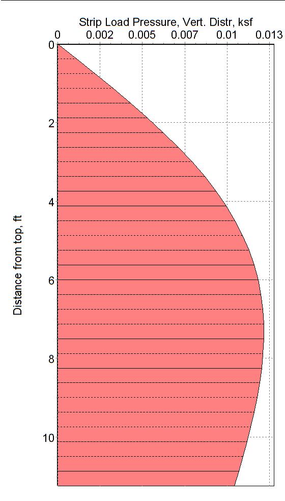
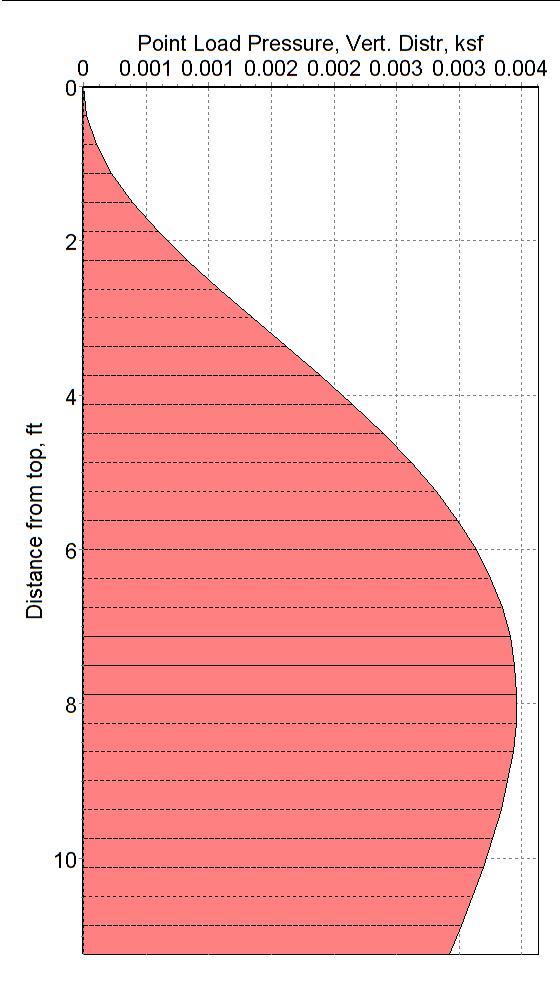
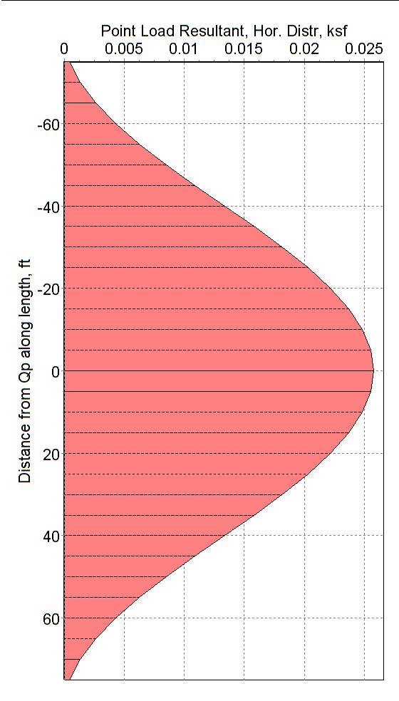
6 Table of Test Results - Backfill Surcharge Output Node # Vert. Height, Strip Load Pr, Line Load Pr, Point Load Pr. Radial Dist Point Load ft ksf ksf (Vert), ksf (Point), ft (Hor), kips
7 Surcharges SoilStructure.com SoilStructure Retaining Wall v2.0 7
8 P-M Diagrams SoilStructure.com SoilStructure Retaining Wall v2.0 8
9 Stem Forces References: 1. ACI : Building Code and Commentary IBC: International Building Code 3. Reinforced Concrete Fundamentals, 5th ed. Ferguson, Breen, & Jirsa, 1988, Wiley 4. Soil Mechanics : Principles and Applications Perloff and Baron, 1976, Ronald Press 5. The Design and Construction of Engineering Foundations, 2nd ed, F.D.C. Henry, 1986, Chapman and Hall 6. Geotechnical Engineering: Foundation Design John Cernica, 1995, Wiley 7. Foundation Analysis & Design, 1988, 4th Ed. J.E. Bowles, McGraw-Hill 8. SoilStructure Software : Retaining Wall v2.0 SoilStructure.com SoilStructure Retaining Wall v2.0 9
Design of Semi gravity Retaining Walls
 Design of Semi gravity Retaining Walls Example 13.1 A semi gravity retaining wall consisting of plain concrete (weight = 145 lb/ft³) is shown in Figure 13.9. The bank of supported earth is assumed to weigh
Advance Design of RC Structure Retaining Wall
 1 Retaining Wall Retaining Walls What are retaining walls Retaining walls are soil-structure systems intended to support earth backfills. Type of retaining walls Gravity retaining wall gravity walls rely
Chapter 13: Retaining Walls
 Chapter 13: Retaining Walls Introduction In general, retaining walls can be divided into two major categories: (a) conventional retaining walls and (b) mechanically stabilized earth walls Conventional
BACKGROUND: SUBSURFACE CONDITIONS:
 2 BACKGROUND: The planned project consists of a prefabricated modular apartment building with underground parking, located on the site bounded by Dexter Avenue N. to the east, multi-story residential/commercial
Lecture Retaining Wall Week 12
 Lecture Retaining Wall Week 12 Retaining walls which provide lateral support to earth fill embankment or any other form of material which they retain them in vertical position. These walls are also usually
Dead man sheet pile wall (SI units)
") Dead man sheet pile wall (SI units) Deep Excavation LLC Software program: DeepEX 2015 Document version: 1.0 January 16, 2015 www.deepexcavation.com Deep Excavation LLC 1 A. Project description In this
Dead man sheet pile wall (SI units) Deep Excavation LLC Software program: DeepEX 2015 Document version: 1.0 January 16, 2015 www.deepexcavation.com Deep Excavation LLC 1 A. Project description In this
HILLCREST MANOR Palo Verde, California
 STRUCTURAL ENGINEERING CONSULTANTS TN358_MAT_RC_desogm_example_040110 HILLCREST MANOR Palo Verde, California Structural Design of Mat (Raft) Foundation First draft ADAPT Corporation Redwood City, CA, USA
Substructure systems, specifically retaining walls
 Design principles of totally prefabricated counterfort retaining wall system compared with existing cast-in-place concrete structures Maen Farhat and Mohsen Issa An alternative to cast-in-place concrete
One-Way Wide Module Joist Concrete Floor Design
 One-Way Wide Module Joist Concrete Floor Design A 1 3 4 30'-0" 30'-0" 30'-0" 3' B 3' C 3' D 3' E 4" 4" (typ.) 3' F 0" 0" (typ.) Figure 1 One-Way Wide Module Joist Concrete Floor Framing System 1 Overview
Precast Concrete Bearing Wall Panel Design (Alternative Analysis Method) (Using ACI )
 (Using ACI )") Precast Concrete Bearing Wall Panel Design (Alternative Analysis ethod) (Using ACI 318-14) Precast Concrete Bearing Wall Panel Design (Alternative Analysis ethod) (Using ACI 318-14) A structural precast
Precast Concrete Bearing Wall Panel Design (Alternative Analysis ethod) (Using ACI 318-14) Precast Concrete Bearing Wall Panel Design (Alternative Analysis ethod) (Using ACI 318-14) A structural precast
16. Design of Pipeline Structures.
 16. Design of Pipeline Structures. a. General. 1) The following guidelines are for the design of structures for water and sewer pipelines including structural concrete and miscellaneous metals design.
Continuous Beam Design with Moment Redistribution (ACI )
") Continuous Beam Design with Moment Redistribution (ACI 318-14) Continuous Beam Design with Moment Redistribution (ACI 318-14) A structural reinforced concrete continuous beam at an intermediate floor level
Continuous Beam Design with Moment Redistribution (ACI 318-14) Continuous Beam Design with Moment Redistribution (ACI 318-14) A structural reinforced concrete continuous beam at an intermediate floor level
ALLOWABLE STRESS DESIGN OF CONCRETE MASONRY LINTELS. TEK 17-1C Structural (2009) Related TEK: Uniform load. Triangular load. Concentrated loads
 Related TEK: Uniform load. Triangular load. Concentrated loads") An information series from the national authority on concrete masonry technology ALLOWABLE STRESS DESIGN OF CONCRETE MASONRY LINTELS TEK 17-1C Structural (2009) INTRODUCTION Lintels and beams are horizontal
An information series from the national authority on concrete masonry technology ALLOWABLE STRESS DESIGN OF CONCRETE MASONRY LINTELS TEK 17-1C Structural (2009) INTRODUCTION Lintels and beams are horizontal
Design Example 2 Reinforced Concrete Wall with Coupling Beams
 Design Example 2 Reinforced Concrete Wall with Coupling Beams OVERVIEW The structure in this design example is a six story office building with reinforced concrete walls as its seismic force resisting
W. Mark McGinley March 3, 2016 ISEA MEETINGS 1
 J.B. SPEED SCHOOL OF ENGINEERING Design of s for Masonry Veneers W. Mark McGinley, Ph. D., PE FASTM MASONRY DAY Indianapolis March 3, 2016 Objectives Present a Brief Overview of: Masonry Veneer Wall systems
DESIGNING AND CONSTRUCTION OF T-WALL RETAINING WALL SYSTEM
 Istanbul Bridge Conference August 11-13, 2014 Istanbul, Turkey DESIGNING AND CONSTRUCTION OF T-WALL RETAINING WALL SYSTEM T. C. NEEL and K.BOZKURT ABSTRACT This work shall consist of the design, manufacture
Structural Option April 7 th, 2010
 Gravity System (Depth Topic I) Post Tensioned Slab A new floor system was designed in an attempt to create a more consistent flooring system throughout the entire building. This new design consists of
S T R U C T U R. Technology. magazine. Software for the Structural Design of Masonry. The Design Basis. Copyright
 Software for the Structural Design of Masonry By Russell H. Brown, James K. Nelson, Jr. and Dennis Graber Using software can free the design engineer from the drudgery of routine calculations and enable
ASD OF CONCRETE MASONRY LINTELS BASED ON THE 2012 IBC/2011 MSJC. TEK 17-1D Structural (2011) Related TEK: 14-7C, 14-13B, 17-1C, 17-2A
 Related TEK: 14-7C, 14-13B, 17-1C, 17-2A") n information series from the national authority on concrete masonry technology SD OF CONCRETE MSONRY LINTELS BSED ON THE 2012 IBC/2011 MSJC TEK 17-1D Structural (2011) INTRODUCTION Lintels and beams are
n information series from the national authority on concrete masonry technology SD OF CONCRETE MSONRY LINTELS BSED ON THE 2012 IBC/2011 MSJC TEK 17-1D Structural (2011) INTRODUCTION Lintels and beams are
Retaining Wall Design
 SIL 211 MEKANIKA TANAH Retaining Wall Design DR. IR. ERIZAL, MAGR DEPARTEMEN TEKNIK SIPIL DAN LINGKUNGAN FAKULTAS TEKNOLOGI PERTANIAN IPB 1 Conventional Retaining Walls Gravity Retaining Structures Stability
DESIGN CALCULATIONS INSTA-FOOTING LOAD BEARING CAPACITIES ON CONCRETE SLAB. January 14, 2017 Rev -
 DESIGN CALCULATIONS INSTA-FOOTING LOAD BEARING CAPACITIES ON CONCRETE SLAB January 14, 2017 Rev - Projection Name: Owner: Prepared by: Insta-Footing Design Calculations Insta-footing, LLC Richard Nolan,
Chapter A-15. CID-MO Structural Analysis
 Kansas Citys, Missouri and Kansas Flood Risk Management Feasibility Study Engineering Appendix to the Final Feasibility Study Chapter A-15 CID-MO Structural Analysis Chapter A-15 CID-MO Structural Analysis
A Guide for the Interpretation of Structural Design Options for Residential Concrete Structures
 CFA Technical Note: 008-2010 A Guide for the Interpretation of Structural Design Options for Residential Concrete Structures CFA Technical This CFA Technical Note is intended to serve as a guide to assist
Reinforced Concrete Tilt-Up Wall Panel Analysis and Design (ACI 551)
") Reinforced Concrete Tilt-Up Wall Panel Analysis and Design (ACI 551) Reinforced Concrete Tilt-Up Wall Panel Analysis and Design (ACI 551) Tilt-up is form of construction with increasing popularity owing
Reinforced Concrete Tilt-Up Wall Panel Analysis and Design (ACI 551) Reinforced Concrete Tilt-Up Wall Panel Analysis and Design (ACI 551) Tilt-up is form of construction with increasing popularity owing
See the IRC for additional information. See CPD-DS Information Bulletin 100 for Requirements for 1 & 2 Family Dwelling plan submittals.
 As a customer service initiative, the Kansas City, Missouri, City Planning and Development Department/Development Services, in cooperation with the Greater Kansas City Home Builders Association, has developed
Structural System. Design Criteria Fire Resistance Concrete designed for 2 HR rating (worst case) Geotechnical Report Allowable Bearing Capacity
 Geotechnical Report Allowable Bearing Capacity") System Codes and Criteria Design Codes and Standards The design code used is the Wisconsin Administrative Code along with the State of Wisconsin Department of Commerce-Safety & Buildings Chapters Comm
System Codes and Criteria Design Codes and Standards The design code used is the Wisconsin Administrative Code along with the State of Wisconsin Department of Commerce-Safety & Buildings Chapters Comm
ADAPT-PTRC 2016 Getting Started Tutorial ADAPT-PT mode
 ADAPT-PTRC 2016 Getting Started Tutorial ADAPT-PT mode Update: August 2016 Copyright ADAPT Corporation all rights reserved ADAPT-PT/RC 2016-Tutorial- 1 This ADAPT-PTRC 2016 Getting Started Tutorial is
DIVISION: METALS SECTION: STEEL DECKING REPORT HOLDER: EPIC METALS CORPORATION 11 TALBOT AVENUE RANKIN, PENNSYLVANIA 15104
 0 Most Widely Accepted and Trusted ICC ES Evaluation Report ICC ES 000 (800) 423 6587 (562) 699 0543 www.icc es.org ESR 2047 Reissued 07/207 This report is subject to renewal 07/209. DIVISION: 05 00 00
CHAPTER 9 STAIR CASES 9.1 GENERAL FEATURES 9.2 TYPES OF STAIR CASES
 CHAPTER 9 STAIR CASES 9.1 GENERAL FEATURES Stair cases are provided for connecting successive floors. It is comprised with flights of steps with inter mediate landings which provides rest to the user and
Downloaded from Downloaded from /1
 PURWANCHAL UNIVERSITY VI SEMESTER FINAL EXAMINATION-2003 LEVEL : B. E. (Civil) SUBJECT: BEG359CI, Foundation Engineering. Full Marks: 80 TIME: 03:00 hrs Pass marks: 32 Candidates are required to give their
Types of Foundations
 Shallow Foundations Types of Foundations Foundations can be classified to two major categories: Shallow. Deep. 1 Introduction If the soil stratum is suitable for supporting the structural loads from the
RETAINING WALL LEVEL BACKFILL
 City of Poway Development Services Department Building Division (858) 668-4645 (858) 668-4646 (Inspection Line) building@poway.org RETAINING WALL LEVEL BACKFILL Construction of retaining walls, except
REINFORCING TABLES INSTALLATION MANUAL
 REINFORCING TABLES 201 REINFORCING TABLES Design Limitations Introduction The structural wall reinforcing and lintel design tables contained within the Appendix of NUDURA s Installation Manual have been
SEAU 5 th Annual Education Conference 1. ASCE Concrete Provisions. Concrete Provisions. Concrete Strengths. Robert Pekelnicky, PE, SE
 ASCE 41-13 Concrete Provisions Robert Pekelnicky, PE, SE Principal, Degenkolb Engineers Chair, ASCE 41 Committee* *The view expressed represent those of the author, not the standard s committee as a whole.
Table of Contents. July
 Table of Contents 36.1 General... 3 36.1.1 Bridge or Culvert... 3 36.1.2 Box Culvert Size Restrictions... 4 36.1.3 Stage Construction for Box Culverts... 4 36.2 Dead Loads and Earth Pressure... 5 36.3
DECORATIVE INTERIOR WALL PANEL FACING SYSTEM
 DECORATIVE INTERIOR WALL PANEL FACING SYSTEM from WALL PANEL SYSTEMS, INC. (WPS) The wall panel system analyzed herein is comprised of colored and textured panels of homogenous phenolic composites. Panels
Grain Silo Strengthening South Dakota. Prepared for Vector Construction Group
 Grain Silo Strengthening South Dakota Prepared for Vector Construction Group May 20, 2002 Table of Contents General...3 nalysis...4 Vertical...4 Horizontal...4 Crack Control...6 Strengthening...7 Vertical...8
Optimum Static Analysis of Retaining Wall with & without shelf /Shelve at different level using finite Element analysis
 Optimum Static Analysis of Retaining Wall with & without shelf /Shelve at different level using finite Element analysis Prof. Dr. D.N.Shinde(Guide) 1, Mr.Rohan R. Watve(Student) 2 Civil Department,PVPIT
How to Design a Singly Reinforced Concrete Beam
 Time Required: 45 minutes Materials: -Engineering Paper -Calculator -Pencil -Straight Edge Design For Flexural Limit State How to Design a Singly Reinforced Concrete Beam Goal: ΦMn > Mu Strength Reduction
REINFORCED CONCRETE WALL BOUNDARY ELEMENT LONGITUDINAL REINFORCING TERMINATION
 1NCEE Tenth U.S. National Conference on Earthquake Engineering Frontiers of Earthquake Engineering July 1-, 1 Anchorage, Alaska REINFORCED CONCRETE WALL BOUNDARY ELEMENT LONGITUDINAL REINFORCING TERMINATION
Design Specifications- Micropile Foundation System. Geopier Calculations
 Design Specifications- Micropile Foundation System Zone Total Piles Average Length (ft) Total Length 1- Primary Area 233 65 15145 2-Radiotherapy Area (Linac Valuts) 70 65 4550 3-Shell Space & ED Canopy
AREMA UNLOADING PIT CALCULATIONS
 AREMA UNLOADING PIT CALCULATIONS AUTHORS Steven P. Lorek, PE (Principal Author) HDR Engineering, Inc. 9987 Carver Road, Suite 200 Cincinnati, OH 45242 Phone: 513.984.7557 Fax: 513.984.7580 Email:Steve.Lorek@hdrinc.com
Slab Bridge Designer 2.1 Help: Example Analysis
 August 21, 2006 Slab Bridge Designer 2.1 Help: Example Analysis Using data from the Portland Cement Association Engineering Bulletin 232, AASHTO LRFD Design of Cast-In-Place Concrete Bridges This example
Design of Anchored-Strengthened Sheet Pile Wall: A Case Study
 Design of Anchored-Strengthened Sheet Pile Wall: A Case Study Ümit Gökkuş* 1, Yeşim Tuskan 2 1 Prof.Dr., Department of Civil Engineering, Celal Bayar University, İzmir, Turkey (E-mail: umit.gokkus@cbu.edu.tr
PE Exam Review - Geotechnical
 PE Exam Review - Geotechnical Resources and Visual Aids Item Page I. Glossary... 11 II. Parameters... 9 III. Equations....11 IV. Tables, Charts & Diagrams... 14 1. Module 1 - Soil Classification... 14
ENGINEERS ENGINEERED SOLUTIONS DEEP-DEK COMPOSITE COMPOSITE LONG SPAN FLOOR DECK.
 ENGINEERS ENGINEERED SOLUTIONS DEEP-DEK COMPOSITE COMPOSITE LONG SPAN FLOOR DECK www.metaldek.com DEEP-DEK 4.5 COMPOSITE DEEP-DEK 6 COMPOSITE DEEP-DEK COMPOSITE Deep-Dek Composite* is a long-span composite
Structural Engineering Library
 Structural Engineering Library Version 5.8 by Michael D. Brooks, S.E., P.E. A product of ENERCALC, INC. ENERCALC All rights reserved. No parts of this work may be reproduced in any form or by any means
Nasser Marafi. Alternate Floor Systems. Pro Con Structural Study of. Technical Report 2. Center & Facility Service Building
 Pro Con Structural Study of Alternate Floor Systems St. Joseph Hospital of Orange Patient Care Center & Facility Service Building Technical Report 2 Professor Andres Lepage STRUCTURAL OPTION October 26th
Nonlinear Modeling of Dynamic Soil-Structure Interaction: A Practitioner s Viewpoint
 Nonlinear Modeling of Dynamic Soil-Structure Interaction: A Practitioner s Viewpoint By (Arul) K. Arulmoli Earth Mechanics, Inc. Fountain Valley, California Workshop on Nonlinear Modeling of Geotechnical
Technical Report 3. Alyssa Stangl Structural Option Advisor Dr. Linda Hanagan L A J O L L A C O M M O N S P H A S E I I O F F I C E T O W E R
 Technical Report 3 Alyssa Stangl Structural Option Advisor Dr. Linda Hanagan L A J O L L A C O M M O N S P H A S E I I O F F I C E T O W E R Site and Location La Jolla Commons, San Diego, California General
CHRISTIAN WHEELER E N G I N E E R I N G
 CHRISTIAN WHEELER E N G I N E E R I N G April 22, 2016 Robert and Michelle Soltys CWE 2150237.03 2038 Cambridge Avenue Cardiff By-The-Sea, California 92007 Subject: Additional Recommendations, Proposed
ANALYSIS AND DESIGN OF MOMENT RESISTING MIDWALL BY THE STEEL NETWORK, INC.
 ANALYSIS AND DESIGN OF MOMENT RESISTING MIDWALL BY THE STEEL NETWORK, INC. Paul Lackey, P.E., Muhammad Ghoraba, Nabil A. Rahman, Ph.D., P.E. and Kurtis Kennedy MidWall is a hold-down product intended to
DIVISION: MASONRY SECTION: CONCRETE UNIT MASONRY REPORT HOLDER: 3B CONSTRUCTION SOLUTIONS, INC.
 0 Most Widely Accepted and Trusted ICC ES Evaluation Report ICC ES 000 (800) 423 6587 (562) 699 0543 www.icc es.org ESR 3788 Reissued 11/2017 This report is subject to renewal 11/2018. DIVISION: 04 00
Numerical Analysis of a Novel Piling Framed Retaining Wall System
 The 12 th International Conference of International Association for Computer Methods and Advances in Geomechanics (IACMAG) 1-6 October, 2008 Goa, India Numerical Analysis of a Novel Piling Framed Retaining
Reinforced Concrete Column Design
 Reinforced Concrete Column Design Compressive Strength of Concrete f cr is the average cylinder strength f c compressive strength for design f c ~2500 psi - 18,000 psi, typically 3000-6000 psi E c estimated
BEARING CAPACITY OF SHALLOW FOUNDATIONS
 BEARING CAPACITY OF SHALLOW FOUNDATIONS Introduction A foundation, often constructed from concrete, steel or wood, is a structure designed to transfer loads from a superstructure to the soil underneath
Structural Technical Report 1 Structural Concepts / Structural Existing Conditions Report
 Michael A. Troxell Structural Option Advisor: Professor Parfitt College of Business Administration Oct. 5, 2005 Structural Technical Report 1 Structural Concepts / Structural Existing Conditions Report
Reinforced Concrete Design. A Fundamental Approach - Fifth Edition
 CHAPTER REINFORCED CONCRETE Reinforced Concrete Design A Fundamental Approach - Fifth Edition Fifth Edition REINFORCED CONCRETE A. J. Clark School of Engineering Department of Civil and Environmental Engineering
FOUNDATION ANALYSIS AND DESIGN
 FOUNDATION ANALYSIS AND DESIGN 4 Michael Valley, P.E. This chapter illustrates application of the 2000 Edition of the NEHRP Recommended Provisions to the design of foundation elements. Example 4.1 completes
E APPENDIX. The following problems are intended for solution using finite element. Problems for Computer Solution E.1 CHAPTER 3
 E APPENDIX Problems for Computer Solution The following problems are intended for solution using finite element analysis software. In general, the problems associated with Chapters 3, 4, and 9 can be solved
 techie-touch.blogspot.com www.vidyarthiplus.com CE2305 FOUNDATION ENGINEERING 2 MARKS QUESTIONS & ANSWERS 16 MARKS QUESTIONS UNIT -1 1. What are components of total foundation settlement? elastic settlement,
Seattle Public Library OMA & REX
 Seattle Public Library OMA & REX Seattle Public Library / General Information Location: Architects: Structural Engineer: Square Footage: Seattle, Washington OMA & REX Arup & Magnusson Klemencic Associates
In-plane testing of precast concrete wall panels with grouted sleeve
 In-plane testing of precast concrete wall panels with grouted sleeve P. Seifi, R.S. Henry & J.M. Ingham Department of Civil Engineering, University of Auckland, Auckland. 2017 NZSEE Conference ABSTRACT:
Design Illustrations on the Use of Soil Nails to Upgrade Loose Fill Slopes
 Design Illustrations on the Use of Soil Nails to Upgrade Loose Fill Slopes Geotechnical Engineering Office and The Hong Kong Institution of Engineers (Geotechnical Division) November 2013 2 Disclaimer
FINITE ELEMENT ANALYSIS OF REINFORCED CONCRETE BRIDGE PIER COLUMNS SUBJECTED TO SEISMIS LOADING
 FINITE ELEMENT ANALYSIS OF REINFORCED CONCRETE BRIDGE PIER COLUMNS SUBJECTED TO SEISMIS LOADING By Benjamin M. Schlick University of Massachusetts Amherst Department of Civil and Environmental Engineering
AC R1 # Triangle Parkway Suite 100 Norcross, Ga Phone: Fax: AC R1. September 11, 2012
 AC70-1012-R1 #12 AC70-1012-R1 #12 AC70-1012-R1 September 11, 2012 Mr. Brian Gerber Ms. Elyse Levy International Code Council Evaluation Service (ICC ES) 5360 Workman Mill Road Whittier, CA 90601 2256 RE:
USE OF 500 GRADE STEEL IN THE DESIGN OF REINFORCED CONCRETE SLAB. Prof. M. Shafiul Bari, Ph.D Department of Civil Engg., BUET
 1.0 Introduction USE OF 500 GRADE STEEL IN THE DESIGN OF REINFORCED CONCRETE SLAB Prof. M. Shafiul Bari, Ph.D Department of Civil Engg., BUET There is growing interest within the reinforced concrete industry
MECHANICAL BRIDGING AND BRIDGING ANCHORAGE OF LOAD BEARING COLD-FORMED STEEL STUDS. Paul E. Lackey, EIT Nabil A. Rahman, Ph.D.
 INTRODUCTION MECHANICAL BRIDGING AND BRIDGING ANCHORAGE OF LOAD BEARING COLD-FORMED STEEL STUDS Paul E. Lackey, EIT Nabil A. Rahman, Ph.D., PE Gary Bennett The purpose of this technical note is to provide
Inlets & Catch Basins
 A Delivering Reliability Inlets & Catch Basins Water-Conveyance & Drainage A Environmentally Responsible Oldcastle Precast to the Rescue All of our products are produced in a controlled environment helping
ACCEPTANCE CRITERIA FOR HELICAL PILE SYSTEMS AND DEVICES PREFACE
 www.icc-es.org (800) 423-6587 (562) 699-0543 A Subsidiary of the International Code Council ACCEPTANCE CRITERIA FOR HELICAL PILE SYSTEMS AND DEVICES AC358 Approved June 2012 Compliance date December 1,
CIVIL BREADTH Exam Specifications
 NCEES Principles and Practice of Engineering Examination CIVIL BREADTH and STRUCTURAL DEPTH Exam Specifications Effective Beginning with the April 2015 Examinations The civil exam is a breadth and depth
Analysis of Redi Rock wall Input data
 Tiverton r. Analysis of Rei Rock wall Input ata Project Task Part Description Customer Author Date Project ID Project number Settings (input for current task) Wall analysis Rei-Rock Wall - Preliminary
Stability of a Mechanically Stabilized Earth Wall
 Stability of a Mechanically Stabilized Earth Wall GEO-SLOPE International Ltd. www.geo-slope.com 1400, 633-6th Ave SW, Calgary, AB, Canada T2P 2Y5 Main: +1 403 269 2002 Fax: +1 403 266 4851 Introduction
> 0. 1 f, they are treated as beam-columns.
 223 A- Flexural Members (Beams) of Special Moment Frames Requirements of ACI 21.5 are applicable for special moment frame members proportioned primarily to resist flexure with factored axial forces 0.
DIVISION: EARTHWORK SECTION: BORED PILES REPORT HOLDER: CANTSINK MANUFACTURING, INC. 71 FIRST AVENUE LILBURN, GEORGIA 30047
 0 Most Widely Accepted and Trusted ICC-ES Evaluation Report ICC-ES 000 (800) 423-6587 (562) 699-0543 www.icc-es.org ESR-1559 Reissued 12/2016 This report is subject to renewal 12/2018. DIVISION: 31 00
Circular tanks on two-parameter Wlasow s elastic subsoil
 Roman Misiak, Ph.D, P.E. Civil Engineer Certified in Specialty Engineering Structures Circular tanks on two-parameter Wlasow s elastic subsoil Abstract: The calculations of concrete tanks in engineering
EZ-Shear Wall for ETABS v1.1
 EZ-Shear Wall for ETABS v1.1 INSTALLATION Download the installation folder and run the EXE file, which will install the program in your PC To uninstall use windows program uninstaller via control panel
Architects and Designers Should Understand Loads Exerted By Rolling Doors
 rchitects and Designers Should Understand Loads Exerted y Rolling Doors It is important for architects and building designers to understand the loads that rolling doors exert on the wall above the opening
Special Reinforced Concrete Structural Walls
 135 Special Reinforced Concrete Structural Walls The requirements of this section apply to special reinforced concrete structural walls serving as part of the earthquake force-resisting system. Shear Strength:
DIVISION: EARTHWORK SECTION: BORED PILES REPORT HOLDER: HELICAL ANCHORS, INC BOONE AVENUE, NORTH MINNEAPOLIS, MINNESOTA 55428
 0 Most Widely Accepted and Trusted ICC-ES Evaluation Report ICC-ES 000 (800) 423-6587 (562) 699-0543 www.icc-es.org ESR-3982 Reissued 09/2017 This report is subject to renewal 09/2019. DIVISION: 31 00
3.5 Tier 1 Analysis Overview Seismic Shear Forces
 Chapter 3.0 - Screening Phase (Tier ) 3.5 Tier Analysis 3.5. Overview Analyses performed as part of Tier of the Evaluation Process are limited to Quick Checks. Quick Checks shall be used to calculate the
Dynamic Earth Pressures - Simplified Methods
 Dynamic Earth Pressure - Simplifed Methods Page 1 Dynamic Earth Pressures - Simplified Methods Reading Assignment Lecture Notes Other Materials Ostadan and White paper Wu and Finn paper Homework Assignment
ICC-ES Evaluation Report Issued July 1, 2011 This report is subject to renewal in one year.
 ICC-ES Evaluation Report ESR-1959 Issued July 1, 2011 This report is subject to renewal in one year. www.icc-es.org (800) 423-6587 (562) 699-0543 A Subsidiary of the International Code Council DIVISION:
Technical Assignment 1 10/8/03
 Executive Summary Technical Assignment 1 10/8/03 The is 55 story high-rise condominium being built off the northern Miami coast. The structural design presented in this building is a direct result of its
ENGINEERED POWER SOLUTIONS
 Date: May 2, 2017 Subject: To: From: Structural Overview of Earth Anchors For PV Ground Mounted Arrays Brian Boguess Nuance Energy Group, Inc. Matthew Gilliss Engineered Power Solutions (EPS) INTRODUCTION
LIGHTWEIGHT FILL DESIGN GUIDANCE
 Preferred Design Procedure LIGHTWEIGHT FILL The Federal Highway Administration (FHWA) and National Cooperative Highway Research Program (NCHRP) have two documents for this technology that contain design
Figure 1 Shear wall segments with mono-sloped top plates
 All text, images and diagrams Copyright 2004 by Thor Matteson and ICC APPENDIX B ENGINEERING PRINCIPLES OF SHEAR WALLS WITH SLOPING TOP PLATES APA The Engineered Wood Association and others have tested
Technical Notes 39A - Testing for Engineered Brick Masonry - Determination of Allowable Design Stresses [July/Aug. 1981] (Reissued December 1987)
![Technical Notes 39A - Testing for Engineered Brick Masonry - Determination of Allowable Design Stresses [July/Aug. 1981] (Reissued December 1987)](/thumbs/75/72632512.jpg "Technical Notes 39A - Testing for Engineered Brick Masonry - Determination of Allowable Design Stresses [July/Aug. 1981] (Reissued December 1987)") Technical Notes 39A - Testing for Engineered Brick Masonry - Determination of Allowable Design Stresses [July/Aug. 1981] (Reissued December 1987) INTRODUCTION Prior to the development of a rational design
Technical Notes 39A - Testing for Engineered Brick Masonry - Determination of Allowable Design Stresses [July/Aug. 1981] (Reissued December 1987) INTRODUCTION Prior to the development of a rational design
Introduction to Decks and Deck Systems
 AASHTO- Load and Resistance Factor Design (LRFD) Introduction to Decks and Deck Systems V 1.1 Rev. 12.03.07 Credits The content for this class has been provided by the following PB employees: Ed Skrobacz,
This is a preview. Some pages have been omitted. Copyrighted by NCEES. For permission to reuse,
 Copyright 2014 by NCEES. All rights reserved. All NCEES sample questions and solutions are copyrighted under the laws of the United States. No part of this publication may be reproduced, stored in a retrieval
Design of Deep Foundations for Slope Stabilization
 Design of Deep Foundations for Slope Stabilization J. Erik Loehr, Ph.D., P.E. University of Missouri Annual Kansas City Geotechnical Conference Overland Park, Kansas April 23, 215 Stability analysis for
NOVEMBER 2017 LRFD BRIDGE DESIGN 14-1
 NOVEMBER 2017 LRFD BRIDGE DESIGN 14-1 14. JOINTS AND BEARINGS Expansion joints and bearings provide mechanisms to accommodate movements of bridges without generating excessive internal forces. This section
JULY 2016 LRFD BRIDGE DESIGN 11-1
 JULY 016 LRFD BRIDGE DESIGN 11-1 11. ABUTMENTS, PIERS, AND WALLS This section contains guidance for the design and detailing of abutments, piers, retaining walls, and noise walls. Abutments and piers are
DIRECT DESIGN METHOD DDM
 DIRECT DESIGN METHOD DDM Load Transfer Path For Gravity Loads All gravity loads are basically Volume Loads generated due to mass contained in a volume Mechanism and path must be found to transfer these
Preview of LEAME Computer Software
 Appendix Preview of LEAME Computer Software Thus far, this book has focused on the fundamental principles and methods for analyzing slope stability using the limit equilibrium method. The computer software
VTU EDUSAT PROGRAMME Lecture Notes on Design of Stair cases
 VTU EDUSAT PROGRAMME 17 2012 Lecture Notes on Design of Stair cases DESIGN OF RCC STRUCTURAL ELEMENTS - 10CV52 (PART B, UNIT 8) Dr. M. C. Nataraja Professor, Civil Engineering Department, Sri Jayachamarajendra
SOILS AND FOUNDATIONS
 CHAPTER 1 SOILS AND FOUNDATIONS This chapter has been revised in its entirety; there will be no marginal markings. SECTION 101 GENERAL 101.1 Scope. The provisions of this chapter shall apply to building
Masonry Wall Bracing. A Simplified Approach To Bracing Masonry Walls Under Construction. Masonry Bracing Task Force.
 Masonry Wall Bracing A Simplified Approach To Bracing Masonry Walls Under Construction Produced by the Masonry Wall Bracing A Simplified Approach to Bracing Masonry Walls Under Construction Produced by
North Mountain IMS Medical Office Building
 North Mountain IMS Medical Office Building Phoenix, Arizona Michael Hopple Technical Assignment 2 October 29 th, 2007 AE 481W-Senior Thesis The Pennsylvania State University Faculty Adviser: Dr. Ali Memari,