Requirements For Electric Service Informational Booklet
|
|
|
- Ezra Johns
- 6 years ago
- Views:
Transcription


1 Vermont Electric Cooperative, Inc. Attn: Engineering 42 Wescom Road Toll Free: ext Johnson, VT Telephone: ext Fax: Requirements For Electric Service Informational Booklet
2
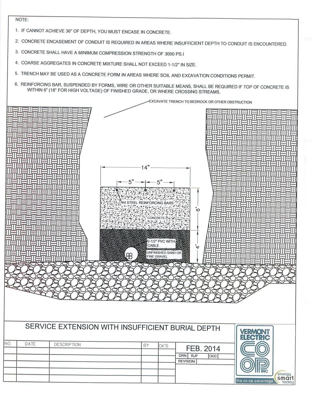
3 Table of Contents Introduction 1 Important information 2 VT Department of Public Safety Division of Fire Safety 3 Characteristics of Service Available 4 Types of Services 4 Voltage Variations 4 Interruption of Service 5 Short Circuit Duty 5 Service Extensions 5 VEC Installed Service Extensions 5 Primary Overhead Service Extensions 6 Number of Services per Building 6 Access to Installation 6 Cost of Service Extensions 7 Prorated Shares 7 Primary Underground Service Extension 8 Overhead Service Extensions 9 Metering 9 Right of Way 10 Customer Utilization Equipment 10 Electric Motor Specifications 11 Safety Precautions 11 Service Entrance Equipment 13 Metering Equipment 14 Instrument Transformer Metering Equipment 15 Metering for Underground Services 16 Requirements for Tree Trimming Distribution Construction Right of Way Clearing (50 ) 19 Distribution Construction Right of Way Clearing (30 ) 20 Clearance Area for Pad Mount Transformers 21 Requirements & Drawings for Construction Wire Matrix 25 Primary Underground Service Specifications 26 Trenching & Conduit Depth for Primary Extensions 28 Service Extensions with Insufficient Burial Depth 29 Primary Underground System 30 Typical Bollard Detail 31 Vault Guarding with Bollard(s) 32
4 Underground Service Specifications 33 Underground Service Pole to Meter on House 34 Underground Service Vault to Meter on House 35 Meter Support Pedestal 36 Clearance Between Electric Meters & L.P./Natural Gas Equipment 37 Overhead Service Specifications 38 Overhead Service Meter on House 40 Mast Overhead Service Specifications 41 Mast Overhead Service Meter on House 43 Mobile Home Service Specifications 44 Mobile Home Service Meter on Pole 45 Mobile Home Service Meter on Stub Post 46 Pole Metering Specifications 47 Pole Metering 49 Temporary Service Specifications 50 Typical Temporary Underground Service 51 Typical Temporary Overhead Service 52 Solar Metering 54
5 Introduction This handbook covers the general requirements for obtaining electric service from Vermont Electric Cooperative, Inc (VEC). It is not intended to provide a complete description of all wiring details or legal requirements. It has been prepared as a guide for prospective members or contractors requesting a new or modified service connection. Complete compliance with this booklet does not relieve the consumer or electrical contractor from installing service entrance equipment or wiring in accordance with the rules and regulations published or followed by the local authority having jurisdiction. The requirements set forth in this document represent VEC s minimum requirements for electric service. These requirements have been formulated to meet the regulations of the National Electrical Code (NEC) and National Electrical Safety Code (NESC). VEC urges all present and prospective members and contractors to consult with the VEC staff early in the planning stage of any new facility or project. By doing so, the member can be assured that adequate electrical capacity will be available at the site, when it is needed, provided all of the requirements outlined in this handbook have been met. Questions concerning any procedure discussed in this handbook should be referred to VEC s Engineering Department at ext
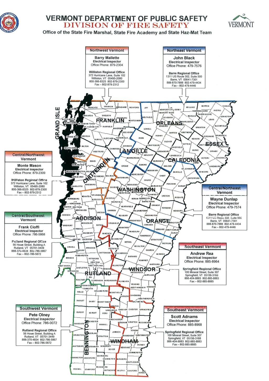
6 Important Information Engineering Office Hours: 7:00 a.m. - 3:30 p.m. Department Telephone Numbers: Field Engineers: ext Engineering/Scheduling Coordinators: ext or 1135 Planning Engineers: Ability to Serve Letters ext Solar ext Right of Way: Herbicide Spraying ext Large Trees ext Distribution Lines -Multiple Trees ext Transmission Lines Multiple Trees ext Solar: Availability to Construct in Current Year ext Digsafe (1-888-digsafe) Telephone Companies: Fairpoint Communications (includes Classic) Franklin Telephone Co Waitsfield Champlain Telecom Vermont State Agencies: Agency of Natural Resources Department of Public Service Public Service Board Vermont Electrical Inspector: 1311 U.S. Route 302 Suite 500 Barre VT
7 3
8 Characteristics of Service Available All electric service supplied by VEC is alternating current (A.C.) with frequency of 60 Hz. (cycles per second) at the nominal voltage and capacity levels indicated below. Single-phase service is readily available in most locations throughout the VEC service territory and the three-phase service is available in certain locations. However, where single or three-phase service is not presently available, but is required to accommodate a member s electric needs, service can usually be extended at the member s expense (covered in the Service Extension section). Types of Service Available 120/240 volts, 3 wire, single phase normally up to a maximum of 100kVA, although higher amounts may be permitted at certain locations, subject to approval by VEC. 208/120Y volts, 4 wire, three phase up to a maximum of 150kVA for an overhead service, and no limit for an underground service. Service at 120/208 volts, 3 wire, single phase network service is also available for customers located in an area serviced by 208Y/120 volts three phase, when the demand for single phase service is incidental to the requirement for three phase service. 480Y/277 volts, 4 wire, three phase up to a maximum of 500kVA for an overhead service and no limit for an underground service. High voltage service is available for large industrial customers or other special applications. Voltage Variation Equipment Ratings Member installed equipment should be rated for operation at the designated nominal voltage class offered by VEC. Ratings that deviate from the nominal service classifications, such as the use of 240 volt motors on a system nominally rated at 208 volts, may result in inadequate performance or failure of the equipment. Voltage Regulation Service provided by VEC is subject to reasonable variations in accordance with industry standards and regulatory requirements. In general, under normal conditions, steady state voltage variation at the meter location will be within +/- 5% of the nominal voltage rating of the designated service classification. While VEC cannot guarantee that all members will experience voltage regulation within this range throughout its distribution system, it will endeavor to take remedial action to improve the regulation of its service voltage where sustained variations outside of this range prevail under normal circumstances. Automatic Protection Any equipment which might be adversely affected by infrequent or long term excursions of the service voltage outside of the normal voltage range should be equipped with suitable automatic isolation protection. Due to circumstances beyond the control of VEC, including but not limited to, instances of 4
9 equipment malfunction or voltage variations originating on other interconnected distribution, transmission or generation system. VEC cannot provide protection for all conceivable system conditions. VEC recommends that member owned equipment be equipped with a protective device in addition to those required by the NEC to guard damage caused by the following events: loss of phase, under-voltage/over-voltage or automatic restart following an interruption. Voltage Drop An allowance must be made for voltage drop in the customer s wiring between the meter location and the terminals of the customer s equipment. Where a member chooses to install their own service extension, VEC strongly advises that such installation adhere to the minimum service and maximum distance specifications (covered in Service Extension Section). Voltage Sensitive Equipment Certain types of utilization equipment, such as a computer or x-ray machines may be sensitive to transient voltage variations. VEC recommends that members with such equipment install auxiliary devices to filter out transient over-voltages or to regulate service voltages with additional precision. Interruption of Service VEC is required to furnish reasonable adequate service. It does not, guarantee continuous service, and does not assume direct or indirect liability for loss or damage to person, property due to its service being furnished to the member s premises or as a result of any interruption or variation in the service supplied. Although VEC strives to provide advanced notice of any interruption required to improve or repair the system, it may from time to time interrupt service to a member without notice in order to perform emergency repairs or improvements to its distribution system or to comply with an order/request of any federal, state, municipal or other authority. Short Circuit Duty VEC s Engineering Department can provide the calculated short circuit duty at a member s service location to assist in selecting service entrance equipment of the proper short circuit rating. In most cases, the short circuit current available on the single phase service to a single residential customer or farm will be less than 10,000 amperes. For commercial, industrial or multi-unit residential building the available short circuit current will depend on the size of the installation and the location of VEC s distribution system and must be calculated independently for each application. VEC Installed Service Extensions Service Extensions VEC will provide service from either overhead or underground service extensions. All service extensions will be installed and maintained in accordance with the provisions of its filed Line Extension Tariff approved by the Vermont Public Service 5
10 Board. A copy of this tariff is available upon request from VEC s Engineering Department. Upon completion of the applicable service application, VEC s engineering staff will visit the site and design a service extension which will meet the needs of the member. Primary Overhead Service Extensions Although VEC normally installs primary overhead, a member may at their option choose to install a service extension or engage the services of an independent contractor to perform this task. All materials must be new, no used poles or etc. In the case of a member installed service extension, VEC will make all final connections to equipment owned and maintained by VEC. For member installed service extensions that will be owned and maintained by the member, the meter shall be located on the structure that terminates VEC and member owned equipment. The member will be responsible to own and maintain all equipment beyond the secondary bushings of the transformer. VEC will not assume ownership and maintenance responsibility for member installed service extension which are not installed in accordance with VEC s rigid guidelines and are not constructed from standard materials used by VEC. VEC s Engineering Department will provide material specifications and installation specifications to assist members to install their own service extensions and who intend to transfer ownership and maintenance responsibility to VEC upon completion. Number of Services per Building Generally only one service shall be installed to a building. Exceptions to this rule may be permitted when the installation of multiple services are required to provide separate metering of portions of a single building or for special circumstances, such as in the case of a separate back up supply to provide standby service for loads requiring an unusually high level of reliability. In such cases, this practice will be permitted only upon approval by VEC and only after receiving authorization (permit) by the State of Vermont Electrical Inspector. When more than a single meter is installed, the cost of electricity delivered through each meter shall be computed separately. Access to Installation VEC, as a condition of service, requires the right to enter the member s premises reasonable times to permit erecting, removing operating or maintaining its service facilities, including the reading and maintaining of meters. VEC shall have the right to operate normal utility construction equipment on the member s premises in the performance of its duty, including line trucks or other mechanized vehicles where conditions permit. At the termination of service, VEC shall have the right to access the premises of the member and remove all property of VEC whether affixed to the realty of the member or not. 6
11 Cost of Service Extension Single phase low voltage electric service from an overhead extension of up to 100 in length is at no charge to applicants for new service of a permanent nature. Applicants, who request service to a meter on a service pole instead of directly to a building the member will be charged for the cost of the service pole and meter installation. For overhead extensions which exceed 100 in length which involve the use of high voltage lines and for all underground service extension the member will be charged the applicable cost under VEC s filed Line Extension Tariff in effort that the time service is rendered, less a credit representing the cost of a 100 low voltage overhead extension. Three phase low voltage electric service from an overhead service extension is available on an actual cost of installation for commercial accounts. High-voltage electric service is available for large industrial customers, wholesale transactions or other special applications. High-voltage services, where required, will be made available on an actual cost basis. Note: Relocation of equipment at the customer discretion requires customers to pay the cost of the relocation. Prorated Shares Whenever more than one customer is connected to said line extension, such contribution in aid of construction, however paid, shall be computed to yield to the Cooperative not more than the total cost of extending or expanding service to the new customer(s) less the service drop credit provided in Section III. Amounts to be collected from new customers connecting to customer financed lines shall be computed as follows: For a period of five (5) years from the completion of construction of a line extension, reimbursement from new customers connecting to said line to customers entitled to reimbursements shall be based upon an equal sharing of the full cost of construction of the subject line extension, adjusted to the percentage used of that line extension to the point of connection. For a period of ten (10) years immediately following the initial five (5) year period discussed above, reimbursement to customers entitled to reimbursements shall be based upon an equal sharing of the full cost of construction of the subject line extension depreciated at a straight line rate to zero at the end of the ten (10) year period, also adjusted to the percentage of the line extension used to the point of connection. For each new transaction (defined as one or more new connections at the same time and location) involving a line that is subject to contribution-in-aid-of-construction payments for new connections within the 15-year reimbursement period, an administrative fee based on actual costs not to exceed $ shall be retained by the Cooperative from the total amount to be reimbursed to customers entitled to reimbursements. If the total amount of all reimbursements owed for each transaction is less than the Cooperative s administrative fee, no reimbursements shall be made. 7
12 All line extension reimbursements less the administrative fee shall be paid by the Cooperative to the current owners of the dwellings or structures served by line extensions that are subject to reimbursement payments for new connections, except that reimbursement payments shall be made to any customer who paid for or contributed to the costs of line extensions and who subsequently sold the dwellings or structures originally served prior to the effective date of the Vermont Public Service Board s Order of September 21, 1999, in Docket Primary Underground Service Extension Underground service is available in all areas at all voltage levels and can be provided directly from either an existing VEC underground or overhead system. VEC tries to accommodate the request for underground service throughout the year. However, VEC reserves the right to postpone construction during winter months due to weather conditions until the following spring. Care of installation To avoid the inconvenience of a premature failure of an underground service extension, care should be exercised during the excavation for and installation of an underground service. To facilitate replacement upon failure as well as to protect the electric cable, VEC requires the use of 2 ½ PVC electrical conduit be used with all primary installed underground service extensions and recommends the use of the conduit in all member installed secondary underground extensions. Material used to back fill the trench must be free of sharp objects or stones larger than 1 in size that are in contact with the PVC. Clearance to other utilities In general, VEC recommends a separation of at least 12 between the conduit system containing the electric service and conduits containing other services such as telephone, cable television or other utilities such as water lines. Where conduit systems are encased in concrete, such clearance may be reduced to not less than 2. Minimum size and maximum length of low voltage service extension VEC recommends for general low voltage service extensions installed and/or owned by the member should not exceed 200 in length. This will avoid excessive service voltage drop and unsatisfactory appliance operation. For member installed single phase 120/240 volt services, VEC recommends a minimum of 1/0 Al. and 4/0 Al. conductor and 100ampere and 200ampere rated services respectively. Service which exceed the recommended maximum distance or which utilize conductor smaller than the recommended size may perform poorly and result in voltage levels which are below the minimum acceptable level for most lighting and appliance applications. The most noticeable effect of excessively long and undersized service extensions in fluctuating intensity levels of incandescent light during appliance operation. 8
13 Member s responsibility - All trenching for underground primary or secondary will be the member s responsibility. Primary will not be back filled until it is inspected by VEC and when approved, the member will back fill and VEC will then own and maintain. Secondary will be owned & maintained by the member. VEC is to be notified at least 24 hours prior to back-filling to have an inspector on site to inspect the trench depth, conduit installation, back fill materials and equipment supports. After approval member can back-fill trench. Overhead Service Extensions Overhead electric service is available from VEC in all areas except those that have been designated for underground service only be zoning regulations, deed restrictions, or other state or local ordinances to which VEC is required to adhere. Point of attachment A low voltage service extension installed by VEC to a building, pole or other supporting structure shall be attached normally at a point at least 16 above ground level near the weatherproof service head. The member shall provide and install the service attachment device that has been specified by VEC. Clearance above ground low voltage extensions The service attachment device shall be located at a sufficient height above ground level to permit a ground clearance for the service conductors of at least 15. Normally this requires an attachment point to be a least 16 above ground level to allow for conductor sage in the service extension or uneven terrain. Where service extensions cross roadways, navigable waterways, or railroad tracks, the service extension shall be designed to accommodate a minimum ground clearance as follows: - Navigable waterways Swimming pools 25 - Roadways 18 - Beyond roof tops 8 - Railroad tracks 27 - Farmland, orchards, etc. 18 Where the buildings height is too low to permit these clearances, attachment shall be made to a service mast, installed by the member, of suitable height and cantilever strength. Metering If the meter is located on the pole the member can furnish materials specified by Engineering and installed by VEC or VEC can supply all materials required at member s cost. In addition, VEC will attach and connect all service conductors at the top of the pole. 9
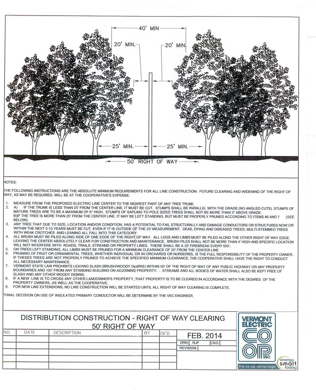
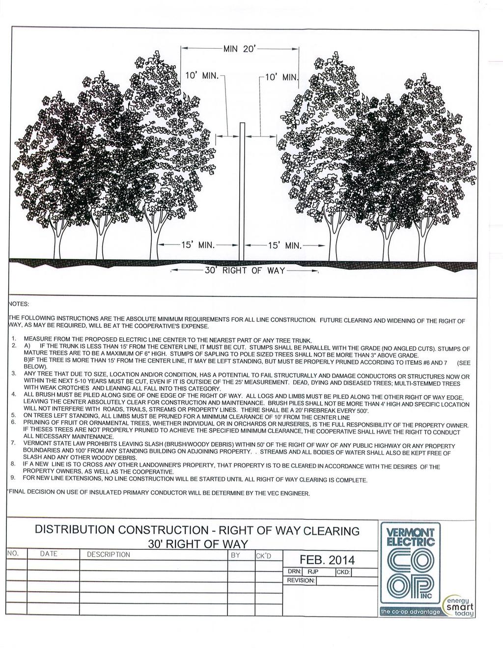
14 If the meter is on a building the member shall furnish and install all equipment on the side of the building and VEC will make final electrical connections between the service entrance cable and the conductors at the point of attachment. Services in excess of 400 amperes, VEC will install current transformers t the top of the pole and metering circuits down the pole in lieu of service conductor. No disconnect switch is used on services in excess of 400amperes. If the meter is located on a post or pedestal the member will furnish and install all equipment associated with the metering location including the support pedestal, stub pole or suitable device to which the meter socket is fastened. The stub pole, post, conduit, pedestal, conductor, meter socket, disconnect and grounds furnished by the member shall be approved by VEC s Engineering Department. Wooden posts used for this purpose shall be pressure treated to resist decay at least 6 in diameter 10 in length and set 4 into the ground. In all cases **the member is responsible to own all equipment beyond the secondary lugs on the transformer**. Right of Way Before VEC can install and maintain service extensions across private property or accept ownership responsibility of member installed service extensions, an easement permitting the perpetual access, erection and maintenance of equipment must be granted to VEC by the landowner(s). In general, easements for overhead service extensions must provide 50 wide corridors, 25 on either side of the center line. A 20 easement is required for underground service extensions, 10 on either side of the center line. This means no obstructions for any kind will be allowed in the right of way. Member s responsibility Unless otherwise agreed to by VEC Unless otherwise agreed to by VEC, a member requesting a service extension shall be responsible for obtaining the necessary easements and a copy of the dead for VEC. Standard easement forms are available from VEC s Engineering Department. The member is also responsible for the right of way clearing in accordance with VEC s specifications. Right of way must be fully cleared before construction of the line extension can commence. Customer Utilization Equipment Fluctuating loads and unusual applications VEC may refuse to supply electric service to electric loads which have unusual characteristics or adversely affect the quality of electric service supplied to other members. In some cases, however, unusual fluctuations or disturbances can be mitigated or eliminated by specifying the type of device which is appropriate for the particular service location or by equipping it with proper controls. In other cases it may be necessary to substantially upgrade VEC s 10
15 distribution system to accommodate the device, often at the member s expense. Customers contemplating the installation of large motors, large welders, x-ray machines, induction furnaces or other special equipment should contact VEC before purchasing and installing this type of equipment. Unbalanced loads In general VEC shall require members to balance load among phases such that at any instance in time the load on each individual phase shall not deviate more than 10% from the average loading of all phases. This is particularly important during peak load periods where substantial unbalance may cause an overload to VEC s service equipment and reduce the efficiency of its delivery system. Exceptions to this rule may be permitted where VEC determines it is necessary to install (at the member s expense) special equipment to accommodate unbalanced loads, or where the load levels are incidental to the capacity of VEC s service equipment. Power Factor Service equipment installed to supply commercial and industrial accounts is designed to provide adequate capacity and operate efficiently at power factors between unity and 95% lagging. Where customer power factor falls outside of this range the customer is urged to install appropriate power factor corrective equipment to avoid unsatisfactory service performance and billing penalties. VEC s Engineering Department can provide guidance to customers seeking to remedy low power energy consumption. Electric Motor Specifications Single phase motors - The maximum size single phase motor (or poly phase motor supplied from a single phase service by use of a converter device) which may be utilized on VEC s distribution system is 10 horse power. Larger sizes may be permitted at the discretion of VEC where adequate facilities exist to minimize the impact of motor starting on VEC s other members. Poly phase motors The maximum size poly phase motor that VEC will permit on its system varies with each location. VEC reserves the right to require poly phase motors in excess of 20 horse power to be equipped with a device to limit the maximum starting current to a designated value. The need to impose an operating limitation or to require motor starting equipment will depend on the frequency of motor starting, the amount and the duration of starting current. VEC s Engineering Department will review each application to ascertain any restrictions that might apply. Safety Precautions The safe distribution and use of electric energy is the responsibility of both the member and VEC. The requirements set forth in this handbook are the result of many years of experience gained in operating electric systems and have been adopted by VEC to ensure the safety and health of its members, employees and contractors. 11
16 Proximity to electric lines VEC s high voltage electric system operates at voltage levels between 2,400 and 48,000 volts. In order to distribute electricity efficiently, bare electric conductors energized at this voltage levels are present on VEC poles at virtually every location where service is rendered. To avoid serious injury or death, consumers are required to comply with the NESC with respect to minimum distances between VEC s line and any other object such as an antenna, balcony, roof, outdoor lights, signs, building and other structures. Where pedestrians routinely access such structures even greater clearance is required. Care must be exercised in erecting antennas, ladders and other tall objects to ensure that this minimum clearance is not exceeded and that the clearance between a person working on the ladder or other structure and an energized conductor is at least this amount. In general, VEC s easement deeds prohibit the construction or erections of antennas, building, structures or other facilities within power line right of ways (usually a distance of 25 from either side of the center line). VEC urges all members, contractors and non-members to consult with its Engineering Department before undertaking work in proximity to VEC s lines. Equipment owned by VEC All work performed on VEC facilities shall be performed by qualified VEC personnel only. An exception to this is permitted for licensed electrical contractors install low voltage equipment at ground level on VEC poles and other structures. However, under no circumstances are contractors not under the employment of VEC allowed to work on VEC poles above ground level or on VEC underground equipment. Electric generators Standby electric generators installed by a member to provide backup service the event of an interruption in the supply of electricity from VEC must be equipped with a suitable isolation device described in the service entrance equipment section. Standby generators not properly equipped with this device present a serious hazard to line workers repairing VEC s line during interruptions. An isolation device is designed to ensure that under no circumstances shall the member s standby generator energizing the VEC s high voltage system. Members contemplating the installation of standby generation equipment to supply all or a portion of the member s electric system must notify VEC and permit VEC to inspect the installation before such equipment is placed in service. Portable standby generators designed to provide backup service to specific appliances in isolation rather than to the member s electric system do not require auxiliary service entrance equipment. Permanently interconnected generators designed to operate in parallel with VEC s system require special protection equipment engineered for the specific application to ensure that the generator is isolated from VEC s system immediately following an interruption or during other emergency conditions. VEC should be contacted well in advance of planning for the installation of interconnected generating equipment to permit sufficient time to evaluate the adequacy of its distribution system to accommodate the interconnection and to determine the proper protective equipment 12
17 that will be required. Studies for large generators that require considerable engineering time and effort will be performed at the expense of the applicant. Disconnections for reasons of health and safety VEC has the authority, as more fully set forth in its Rules and Regulations, to disconnect electric service to a member s property when necessary to protect the health and safety of the member, employee of VEC or the general public. Where possible, VEC will strive to provide the member with a reasonable amount of time to correct the deficiency before disconnecting service. However, in cases where the condition represents a serious, imminent health or safety threat, VEC may be required to disconnect service with minimal, if any advanced notice. Service Entrance Equipment Service entrance equipment is all low voltage equipment installed by the member beyond the point of attachment of VEC s service extension up to and including the member s main service entrance panel. Service entrance conductor This is the wiring that connects the point of attachment of VEC s service extension to the meter socket and member s service entrance, disconnect and panel. Service entrance wiring installed by a member shall be sized, installed and related for service entrance application in accordance with the NEC or other code of the local authority having jurisdiction. Service entrance conductor supplied for an overhead service extension shall be equipped with an approved weatherproof service head. At least 3 of exposed conductor shall be available beyond the service head to permit VEC to make the final connections to the service entrance. Service entrance disconnect The service entrance disconnect shall be mounted in an accessible location near the point where the service entrance conductors enter the building. Normally disconnects are installed on the load side of the meter, except in some multiple occupancy buildings where it may be necessary to install a line side disconnect. A disconnect installed on the line side of the meter shall be of the enclosed type with provisions to accommodate sealing by VEC. The fuse or breaker reset lever must be accessible without removing the seal and cover. Where multiple service entrance disconnects are installed for multiple occupancy buildings, each disconnect (and associated meter socket where applicable) shall be marked in a conspicuous and permanent manner to indicate the service account which it controls. In general, VEC recommends that all service entrance disconnects installed have a rating of not less than 100 amperes. Grounding A permanent grounding system meeting the requirements of NEC 13
18 shall be furnished at all service entrance installations. A properly constructed ground electrode system meeting the requirements of Article 250 of the NESC is essential to the safe operation of an electric service operating at any voltage level. Members are advised to seek the assistance of a qualified electrician when planning the installation of a ground system. The ground electrode system shall be bonded through suitable rated conductors to the grounded conductor of the service entrance conductor at the meter socket location or the service entrance disconnect location in accordance with the provisions of the NEC. All metallic conduit, meter enclosures and service entrance panels shall be connected appropriately to the grounding system as required by the code. Standby generators Service entrance equipment associated with standby generators installed to supply all or part of a member s electrical requirements in the event of an interruption to VEC s supply shall consist of a double throw transfer switch designed to prevent the interconnection of the ember s generator with VEC s system. Member s contemplating the installation of a standby generator must notify VEC in advance of installation and permit VEC to inspect the installation to ensure that the service entrance transfer switch will meet the requirements of VEC. Metering Equipment Metering types All energy supplied by VEC will be measured by electric meters furnished and owned by VEC. VEC employs a variety of different types of meters to accurately measure electric use sold under each of its tariffs. In general, for services that are either greater than 200amperes and/or larger than 300 volts, VEC utilizes instrument rated meters designed with current and/or potential transformers. Below these levels, VEC uses self-contained meters that do not require provisions for instrument transformers. A member or contractor should consult with VEC to review the type of meter socket that is required for the specific service being requested. Most meters used by VEC employ spade type terminals. However, in the case of some instrument rated installations, VEC utilizes so-called A-base or bottom connected meter. Meter locations and heights Meters for single occupancy buildings and small multiple occupancy buildings must be located outside the building, and in a location approved by VEC which is easily accessible to VEC s meter reading and maintenance personnel. In large multiple occupancy buildings, meters may be located inside the building in a single common area approved by VEC. Indoor meters must be located in a dry and clean area that is accessible to VEC s meter personnel at all times. Where access is restricted at any time, a lock box containing the building key (but accessed by VEC s standard key) shall be provided on the exterior of the building. Single electric meters shall be installed at a height between 5 to 5 6 above 14
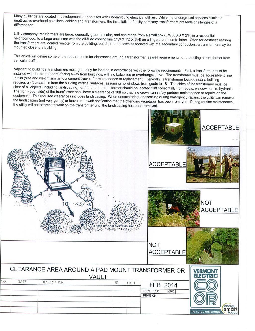
19 finished grade. Multiple metering installations that cannot accommodate all meters within a range of 5 to 5 6 above finished grade may utilize the space below this level down to a minimum height of 3 above floor level or finished grade. In general, meters shall be located at or near the division of ownership between supply facilities owned by VEC and the service equipment installed and owned by the member. Mounting All meter sockets shall be mounted plumb and securely fastened to support with screws. On masonry support, expansion bolts and anchors shall be used. Outdoor meter sockets shall be made water-tight at all conduit or conductor entrance positions. Self-contained meter sockets members are required to furnish and install meter sockets for self-contained meters, except in the case of a meter mounted on a pole. All meter equipment associated with a meter on a pole will be supplied and installed by VEC and billed to the member. Member supplied meter sockets shall be Underwriter s Laboratories (U.L.) approved, and shall include a locking provision that will enable VEC to lock the socket with a meter seal after the meter is installed. The incoming line side conductors must always be connected to the top terminals of the meter socket. Instrument rated meter sockets The proper meter sockets together with the appropriate instrument transformer enclosures, transformers and test switches for use with instrument rated meters shall be furnished by VEC (at the member s expense), but installed by the member s electrical contractor unless otherwise agreed to by VEC. VEC will wire the metering installation after this equipment has been installed in place by the contractor. VEC may permit other arrangements on occasion upon agreement. Exception: In the case of a metal-clad freestanding service entrance equipment, VEC will permit the use of a separate, completely isolated compartment for its instrument transformers, provided the size and design meet the approval of VEC. Meter sockets installed in conjunction with free standing service entrance equipment may be mounted separately from, but not more than 50 away from the instrument transformer compartment. Instrument Transformer Metering Equipment Enclosure for transformers Except in the case of a service metered on a pole, an enclosure is required to house the instrument transformers used for metering services up to 600 volts. VEC will furnish a suitable enclosure for the member s contractor to install. Normally the instrument transformer enclosure shall be mounted near but ahead of the main service disconnect. Exception 1: Instrument transformers for metering high voltage service (over 600 volts) will be mounted on the pole or in the case of an underground service within a 15
20 special pad mounted enclosure provided by VEC. Exception 2: Commercial and industrial buildings which utilize metal-clad switch gear or free standing service entrance equipment may provide separate and sealable instrument transformer compartments as an integral component of the switch gear or service entrance equipment. VEC s Metering Department should be consulted during the planning stages to ensure that adequate space and access provisions for VEC s metering equipment are included within the member s service entrance equipment. Exception 3: Where single or three phase service under 300 volts (but over 200 amperes) is rendered to a pole rather than to a building, in most cases, the necessary current transformers can be mounted on the pole eliminating the requirement for an instrument transformer enclosure. Instrument transformer enclosures shall not be used to contain or terminate other wiring not associated with the function of metering a member s electric load. Only service entrance conductors to be metered shall enter and leave the transformer enclosure and no branch circuit connections or other equipment shall be permitted inside the enclosure. The member s contractor shall install 1 ¼ conduit between the instrument transformer enclosure and the meter socket. In general, the meter socket shall be mounted with 15 of the transformer enclosure. The instrument transformer enclosure will be locked and sealed by VEC when the meter has been installed. After sealing, entry to the instrument transformer enclosure and meter socket is expressly prohibited unless authorized by VEC. Transformer VEC will furnish and install all instrument transformers used in conjunction with metering a member s service. VEC will wire the secondary metering circuits and furnish and install a test switch between the meter and instrument transformer. Metering for Underground Services Meter pedestals As noted in the Underground Services Extension, low voltage services installed by the member may under some circumstances be metered on a meter pedestal. Normally this will occur when a member elects to run his or her own low voltage service extension from VEC s existing underground system. Meter pedestals are free standing posts, stub poles or commercially available metallic supports to which the meter socket and associated equipment is affixed. Pedestals must be installed at least 4 into the ground and permit the meter to be installed at a height of 5 to 5 6 above the ground. Pedestals made of wood must be pressure treated to resist decay. Metering pad mounted transformers - Where it is convenient to do so and only a single service is contemplated, VEC will permit instrument rated metering to be installed in conjunction with the pad mounted transformer supplying the member. 16
21 Vermont Electric Cooperative, Inc. Requirements For Tree Trimming
22
23 19
24 20
25 21
26

27 Vermont Electric Cooperative, Inc. Requirements And Drawings For Construction
28
29 Wire Matrix SUGGESTED CONDUCTOR SIZES RESIDENTIAL 120/240 VOLT SERVICES ONLY RATING CONDUCTOR LENGTH* ALUMINUM CONDUCTOR CONDUIT 100A FT #2 2 ½ FT 1/0 2 ½ FT 2/0 2 ½ FT 4/0 2 ½ FT 350 MCM FT 500 MCM 3 150A FT 2/0 2 ½ FT 4/0 2 ½ FT 350 MCM FT 500 MCM 3 200A FT 4/0 2 ½ FT 350 MCM FT 500 MCM 3 *Conductor length is the total of trench and riser lengths. This chart does not indicate that the conductor can be pulled into conduits of these lengths. Pulling calculations are necessary to make that determination. Primary Underground Conduit: Trench: Pole Sweeps: Secondary Underground Conduit: Trench: Schedule 40 Electrical PVC 3 in depth with safety tape 6 down from grade 90 degree Schedule 80 Electrical PVC or IMC steel Schedule 40 Electrical PVC with frost sleeve 2 in depth with safety tape 6 down from grade Secondary Loop (Riser for Pole): Schedule 80 Electrical PVC 25
30 PRIMARY UNDERGROUND SERVICE 1. All wiring and materials shall conform to the requirements of NEC and to any applicable local codes. Where conflict exists the more stringent code will apply. For customer owned equipment any requirements in excess of code specified minimums are recommended not required. 2. The location of the pole conduit riser will be designated by a VEC representative. The pole mounted riley bracket used to attach the underground conduit will be provided by the utility. Any relocation must be approved by a VEC representative. 3. All trenching and back filling shall be provided by the member. If ledge is encountered the member shall do the blasting or whatever means is necessary to remove the ledge to the required trench depth. 4. Depths are 36 but allowances based on the NESC may be made where obstructions such as ledge are encountered but must be approved by a VEC representative. Any portion of conduit shallower than 24 shall be covered by a minimum of 6 concrete cap. 5. The bottom of all trenching shall be of uniform pitch and not undulation. 6. Unfrozen sand or fine gravel that will pass through a 1 mesh screen shall be used to form a 4 cushion on all sides of the conduit. The balance of the trench may be random-fill with no stones greater than 3 in dimension. No foreign materials such as wood, glass, etc. shall be in the back fill. 7. Marking tape will be put into the trench and is to be buried by the customer at the depth of 8-12 below final grade. VEC is to be notified at least 24 hours prior to backfilling to have an inspector on site to inspect the trench depth, conduit installation, back fill materials and equipment supports. After approval member can back-fill trench. 8. On private roads, driveways or public roadways, the underground cable shall normally be installed within a 10 strip outside and adjacent to the road right of way. 9. A vaults with transformer must be accessible to the utility s vehicles. A road will have to be built for access at the member s expense if required by VEC. 10. Vaults must be installed in tamped or undisturbed earth covered with 12 of crushed stone that will pass through a 1 mesh screen and must be must be installed level with approximately 4 rising above finished grade. 11. In wet locations a sectionalizing cabinet may be installed above the water table. 12. When possible the vault must have drainage of a 4 perforated drain line extending to the surface. 13. The primary conduits must enter the vault as straight as possible and by using the holes on the long end of the vault. 14. The pre-cast or poured on-site concrete base for 3 phase pad mounted electrical equipment shall be applied and installed by the member in accordance with specifications provided by the utility. 15. On 3 phase pad mounted electrical equipment, as you are facing the unit, the primary conduit enters on the left and the secondary conduit enters on the right. 16. The member shall leave a pull rope in the conduit to assist pulling in the 26
31 conductor. The rope shall have a minimum pulling strength of 500 pounds for all cable sizes. 17. VEC shall specify the type, size and composition of the electrical conduit to be used. 18. All vertical 90 degree bends shall have 36 radius. 19. Schedule 40 and schedule 80 PVC electrical conduit shall not be mixed in conduit run within the trench. The conduits have the same outside diameters. However, the inside diameters differ which could cause conductor insulation damage. 20. A grounding grid shall be placed around all primary vaults. The wire shall be #4 stranded copper, buried to a depth of 6-12 around the entire vault and attached to the 2 ground rods driven outside the vault. 21. The driven ground rod shall be a minimum of 5/8 in diameter and 8 in length. 22. The utility must be notified at least 48 hours prior to back filling in order to have an inspector on site. The VEC field representative must inspect the trench, installation of conduit, back fill material and equipment supports before back filling can be done. When calling in for the inspection do not leave a message unless it is after hours, please speak with a Field Engineering or Operations & Engineering Coordinator. 23. Bollards will be used where the VEC field representative requires. 27
32 28
33 29
34 30
35 31
36 32
37 UNDERGROUND SERVICE 1. All wiring and materials shall conform to the requirements of the NEC and to any applicable local codes. Where conflict exists the more stringent code will apply. For customer owned equipment, any requirements in excess of code specified minimums, are recommended not required. 2. This specification covers residential services. Commercial service equipment is under the jurisdiction of the electric inspector. The cable sizes shown in the chart may not apply to commercial services. 3. The location of the conduit risers and the meter socket at any location will be designated by a VEC representative. Any relocation shall be approved by a VEC representative. 4. All meter sockets on service requiring large capacity (200amp or greater) shall have a manual bypass with a locking jaw device. The meter socket shall have a separate grounding electrode conductor connector. The connector shall be appropriately connected to the service neutral bus. The grounding electrode connection will normally be made in the meter socket. The service neutral, and not the grounding electrode conductor, shall extend from the meter socket to the main disconnect. 5. The grounding electrode conductor, to a driven ground, shall be a minimum of #6 copper. The conductor shall be adequately protected. The driven grounds shown shall be a minimum of 5/8 in diameter and 8 in length. 6. Any steel conduit within 18 of the surface shall be bonded. Steel conduit is not required. 7. Any construction, at the pole, required by the member will be approved by the designated VEC representative. 8. Depth shallower than 24 may be allowed where obstruction such as ledge are encountered. Any portion of the conduit shallower than 24 shall be covered by a minimum of 6 concrete cap. 9. All gas valves shall be a minimum of 10 from electric meter equipment. For clearances less than 10 see NFPA The service disconnecting means shall be installed at a readily accessible location, either outside of a building or structure, inside a building or structure nearest the point of entrance of the service conductors, not to excess 10 conductor length, from the point of entrance. Local jurisdictions may specify a shorter distance. 11. The chart shows the acceptable total cable length for given service amp ratings and conductors. The chart is based on a maximum 3% voltage drop in an aluminum underground service cable for 120/240 volt service. For other voltages, cable or multiple cables consult your local utility. 12. All marker tap shall be installed, above the conduit, 12 below grade. Type USE cable shall be marked or listed sunlight resistant. 13. A side bar meter socket is required if 350 MCM cable is used. 33
38 Vermont Electric Coopertive, Inc. Pole to Meter on House 34
39 Vermont Electric Coopertive, Inc. Vault to Meter on House 35
40 36 5 MIN
41 Vermont Electric Coopertive, Inc. Clearance for L.P. or Natural Gas Equipment 37
42 OVERHEAD SERVICE 1. All wiring and materials shall conform to the requirements of the NEC and to any applicable local codes. Where conflict exists the more stringent code will apply. For customer owned equipment, any requirements in excess of code specified, minimums are recommended not required. 2. The point of attachment of the service drop and the location of the meter socket will be designated by a VEC representative. Any relocation shall be approved by a VEC representative. 3. On low buildings, without the minimum of 15 clearance, a mast with guy wire shall be required. 4. The service drop will not be allowed to be attached on or under the eaves. 5. In areas subject to truck traffic, the clearance required to the service drop, is a minimum of 16, under the ice loading conditions described in the NESC. If the overhead service is owned by the customer, rather than the utility the clearance required is a minimum of 18 under the conditions described in NEC (no loading at 60 degrees Fahrenheit). In areas only subject to pedestrian traffic, the clearance required to the service drop, is a minimum of 12, under the ice loading conditions described in the NESC. 6. All meter sockets on services requiring large capacity (greater than 200amps) shall have a manual bypass with a locking jaw device. The meter socket shall have a separate grounding electrode conductor connector. The connector shall be appropriately connected to the service neutral bus. The grounding electrode connection shall normally be made in the meter socket. The service neutral, and not the grounding electrode conductor, shall extend from the meter socket to the main disconnect. 7. The grounding electrode conductor, to a driven ground, shall be a minimum of #6 copper. The conductor shall be adequately protected. The driven rods shown shall be a minimum of 5/8 in diameter and 8 in length. 8. All gas valves shall be a minimum of 10 from electric meter equipment. For clearances less than 10 see NFPA The service disconnection means shall be installed at a readily accessible location, either outside of a building or structure, or, inside a building or structure nearest the point of entrance of the service conductors, not to exceed 10 of conductor length, from the point of entrance. Local jurisdictions may specify a shorter distance. 10. The service drop cable and its drip loop shall have a clearance of 3 from any accessible opening such as to the side of an operable window, top of a doorway, a balcony or to the side of a fire escape. No clearance is required directly above a window. If the opening is used for access for people or materials, then service cables shall not be placed below the opening see NEC Article All services, unless the exceptions of note 12 or 13 apply, shall have a clearance of 8 from the roof. That clearance is required above the roof and 3 beyond the edge of the roof. The service drop may attach to the side of the building. 38
(Condensed from National Electric Code)
") WIRING, SPECIFICATIONS, INSPECTION, AND METER INSTALLATION PROCEDURES FOR RESIDENTIAL CUSTOMERS SERVED BY SOUTHWEST ARKANSAS ELECTRIC COOPERATIVE CORPORATION Effective April 1, 1974 Revised February 3,
WIRING, SPECIFICATIONS, INSPECTION, AND METER INSTALLATION PROCEDURES FOR RESIDENTIAL CUSTOMERS SERVED BY SOUTHWEST ARKANSAS ELECTRIC COOPERATIVE CORPORATION Effective April 1, 1974 Revised February 3,
Basic Service. This Section provides information regarding a. Introduction
 Basic Service Introduction This Section provides information regarding a new electric Basic Service for a single phase service less than or equal to 400 amps, and a three phase service less than 50kW.
Section 2: Underground
 Section 2: Underground GENERAL INSTALLATION REQUIREMENTS FOR UNDERGROUND FACILITIES Underground electric service and meter location will be established by NHEC upon site visit. In some instances the type,
PRIMARY LINE EXTENSION
 PRIMARY LINE EXTENSION Installation of new electric service to an empty parcel/lot or extending a transformer to within 150' of proposed meter location. This includes installing a permanent branch, addition,
Contact Clark Public Utilities Construction Services department at (360) to initiate a request for service.
 to initiate a request for service.") CHAPTER3 Clark Public Utilities Commercial Electric Service Handbook Commercial Underground Services Preparing for the installation The following checklist will assist in preparing a project for the installation
CHAPTER3 Clark Public Utilities Commercial Electric Service Handbook Commercial Underground Services Preparing for the installation The following checklist will assist in preparing a project for the installation
Large Basic Service. This Section applies to members requiring new. Introduction. Service Types
 Large Basic Service Introduction This Section applies to members requiring new Large Basic electric service installations, greater than 400 amps single phase and greater than 50kW three phase. This Section
Electric Service Handbook
 Electric Service Handbook Revised August 2017 Contact Information Telephone (253): Electrical Inspection Office 502-8277 7:30 am - 4:30 pm Electrical Inspectors Area Map on Website 7:30 am - 8:30 am Automated
UNDERGROUND SERVICES SECONDARY
 Reference UNDERGROUND SERVICES SECONDARY Underground services secondary... U- 1 General requirements for underground service... U- 2 Name of parts for underground service... U- 3 Conduit layouts... U-
DOWNTOWN UNDERGROUND NETWORK SECONDARY SERVICES GUIDELINES
 Guidelines effective March 5, 2007 NES is committed to providing safe, reliable electric service at a reasonable price for all of our customers. These guidelines offer direction for activities relating
Welcome to Douglas County PUD
 Welcome to Douglas County PUD We are committed to providing the best possible utility services at the lowest possible cost consistent with sound business principles. To better serve you, please fill out
TEMPORARY METER POLE INSTALLATION
 TEMPARY METER POLE INSTALLATION MEMBER PROVIDED Location to be made by REMC within 50' of our transformer or existing service Temporary pole to be properly braced 24" 3 wire weatherhead (located 24" from
Electric Service Standards
 V: 1 of 6 A. Padmounted Requirements Complete requirements are contained in FPL specifications given to Customers for individual projects. Typical pad mounted transformer requirements include, but are
ELECTRICAL SERVICE UPGRADE RESIDENTIAL AND COMMERCIAL QUICK INFORMATION REFERENCE
 ELECTRICAL SERVICE UPGRADE RESIDENTIAL AND COMMERCIAL QUICK INFORMATION REFERENCE PROVO CITY POWER STANDARDS ELECTRICAL ENGINEERING UPDATED: 2015 SPECIFICATIONS SUBJECT TO CHANGE WITHOUT NOTIFICATION.
Effective June, Eaton-Durham Model # UTRS223ACH. Siemens, Model # SUAS877-PG. (or Landis & Gyr # UAS877-PG) Milbank. Model # U1980-O.
 Milbank. Model # U1980-O.") Siemens, Model # SUAS877-PG (or Landis & Gyr # UAS877-PG) Eaton-Durham Model # UTRS223ACH Milbank Midwest Model # U980-O UTRS223AMEP These are some examples of the single meter sockets we require for underground
Siemens, Model # SUAS877-PG (or Landis & Gyr # UAS877-PG) Eaton-Durham Model # UTRS223ACH Milbank Midwest Model # U980-O UTRS223AMEP These are some examples of the single meter sockets we require for underground
NORTHWESTERN UNIVERSITY PROJECT NAME JOB # ISSUED: 03/29/2017
 SECTION 26 0526 - GROUNDING AND BONDING FOR ELECTRICAL SYSTEMS PART 1 - GENERAL 1.1 RELATED DOCUMENTS A. Drawings and general provisions of the Contract, including General and Supplementary Conditions
CUSTOMER SERVICE POLICIES
 Resolution U-10670 Effective December 18, 2013 Section Title Page No. 1.0 Statement of General Policy... 2 2.0 Electrical Service... 3 2.1 Electrical Service Availability and Characteristics... 3 2.2 Large-Load
WIRING METHODS CHAPTER 38
 CHAPTER 38 WIRING METHODS SECTION E3801 GENERAL REQUIREMENTS E3801.1 Scope. This chapter covers the wiring methods for services, feeders and branch circuits for electrical power and distribution. E3801.2
ELECTRIC METERING GENERAL
 1.0 INDEX 1.0 INDEX 2.0 SCOPE 3.0 GENERAL REQUIREMENTS 4.0 EQUIPMENT 5.0 METER REQUIREMENTS 6.0 METER FACILITIES 7.0 ELECTRICAL CONNECTIONS 2.0 SCOPE This guide covers general requirements and codes for
SERVICE ENTRANCE SPECIFICATIONS FOR RESIDENTIAL AND COMMERCIAL
 SERVICE ENTRANCE SPECIFICATIONS FOR RESIDENTIAL AND COMMERCIAL 0 3000 AMPERES AT SINGLE-PHASE, 3 WIRE THREE-PHASE, 4 WIRE 120/240 VOLTS 120/240 VOLTS * 240/480 VOLTS 277/480 VOLTS Y 120/208 VOLTS 120/208
Specifications for Electrical Underground Residential Distribution Systems
 Specifications for Electrical Underground Residential Distribution Systems Specification DDS-2 Revision 13, February 2010 ONCOR ELECTRIC DELIVERY COMPANY SPECIFICATIONS FOR ELECTRICAL UNDERGROUND RESIDENTIAL
COMMERCIAL CONDUIT RULES AND REGULATIONS
 Electric Engineering Division COMMERCIAL CONDUIT RULES AND REGULATIONS S:\COO_ACM_US_Electric_Telecommunications\COO_ET_Engineering\Conduit Policies B - 1 1805 NE 30th Ave., Bldg. 400 Ocala, FL 34470-4875
Underground Residential Distribution (Specifications for Installation) PES March 2008 Spec 11
 PES March 2008 Spec 11") Underground Residential Distribution (Specifications for Installation) PES March 2008 Spec 11 Underground Residential Distribution (URD) Index General Discussion... 1-2 Description... 3-7 Drawings (Available
Underground Residential Distribution (Specifications for Installation) PES March 2008 Spec 11 Underground Residential Distribution (URD) Index General Discussion... 1-2 Description... 3-7 Drawings (Available
2008 NEC Guide Lines for Home Owner Doing Electrical Work on their Property
 2008 NEC Guide Lines for Home Owner Doing Electrical Work on their Property A brief summary of the most used code references for residential wiring State of Idaho Division of Building Safety Electrical
WIRING RULES AND REGULATIONS OF TOMBIGBEE ELECTRIC POWER ASSOCIATION
 WIRING RULES AND REGULATIONS OF TOMBIGBEE ELECTRIC POWER ASSOCIATION The following rules and information are issued to make it possible for anyone engaged in electrical wiring or installation of electrical
SECTION GROUNDING AND BONDING
 SECTION 16060 PART 1 GENERAL 1.01 DESCRIPTION A. Section includes requirements for an electrical grounding system, including electrodes, grounding rods, connectors, insulators, equipment grounding and
Underground Service Requirements and Instructions
 This packet includes all FKEC underground service requirements, instructions, procedures and drawings. If you are considering underground power service please review this document in its entirety (3 page
A. Product Data shall be provided for each type of product indicated.
 32 31 13 CHAIN LINK FENCES AND GATES SECTION 1 GENERAL 1.1 SUMMARY This Section includes the following: 1. Chain Link Fences 2. Gates for Chain Link Fences. See electrical specifications for electrical
Title: YALE OFFICE OF FACILITIES PROCEDURE MANUAL Chapter: 01 - Yale Design Standard Division: Electrical Standards
 Date Description of Change Pages / Sections Modified ID 6/15/16 Updated format, division title, and removed references to other sections. - mgl44 A. Summary This section contains design criteria for the
Energy Delivery Service Guide
 Energy Delivery Service Guide Connecting to Gainesville Regional Utilities TM M o r e t h a n E n e rg y. January 17, 2018 Volume 1, Issue 36 TM . A reference guide for planning and designing electric
Southern California Edison Revised Cal. PUC Sheet No E Rosemead, California (U 338-E) Cancelling Revised Cal. PUC Sheet No.
 Cancelling Revised Cal. PUC Sheet No.") Southern California Edison Revised Cal. PUC Sheet No. 24700-E Rosemead, California (U 338-E) Cancelling Revised Cal. PUC Sheet No. 22993-E Rule 16 Sheet 1 Applicability: This rule is applicable to both
Southern California Edison Revised Cal. PUC Sheet No. 24700-E Rosemead, California (U 338-E) Cancelling Revised Cal. PUC Sheet No. 22993-E Rule 16 Sheet 1 Applicability: This rule is applicable to both
All service lines shall conform to the following requirements:
 505 WATER SERVICE INSTALLATION 505.1 DEFINITION A service line is comprised of the piping and related appurtenances including the connection installed from the Des Moines Water Works water main to the
CONDUITS AND FITTINGS
 CONDUIT AND FITTINGS Rigid Steel Conduit 3801 Rigid PVC Conduit 3803 HDPE Conduit 3803 Flexible Non Metallic Liquid Tight Conduit Type LFNC-B 3804 PVC Coated Urethane Lined Galvanized Rigid Steel Conduit
Temporary Wiring Practices And Guidelines For NECA. National Electrical Contractors Association Omaha, Nebraska
 Temporary Wiring Practices And Guidelines For NECA National Electrical Contractors Association Omaha, Nebraska Table of Contents I. Planning II. Lighting and Power III. Maintenance IV. Inspections V. Routing
Gainesville Technical Center 5399 Wellington Branch Drive Gainesville VA Phone (703)
") Gainesville Technical Center 5399 Wellington Branch Drive Gainesville VA 20155 Phone (703) 754-6750 Work Request # UNDERGROUND DISTRIBUTION FACILITIES AGREEMENT (FOR COMMERCIAL CUSTOMER) Developer/Builder/Owner
Gainesville Technical Center 5399 Wellington Branch Drive Gainesville VA 20155 Phone (703) 754-6750 Work Request # UNDERGROUND DISTRIBUTION FACILITIES AGREEMENT (FOR COMMERCIAL CUSTOMER) Developer/Builder/Owner
ITEM L-119 AIRPORT OBSTRUCTION LIGHTS DESCRIPTION
 SECTION 74 AIRPORT OBSTRUCTION LIGHTS (FAA L-119) 74-1 GENERAL The Contractor shall perform all work required by the plans and specifications for construction of obstruction lights in accordance with the
CONSOLIDATED EDISON COMPANY OF NEW YORK, INC Van Dam Street Long Island City, NY ELECTRIC METER SHOP DEPARTMENT
 CONSOLIDATED EDISON COMPANY OF NEW YORK, INC. 48-05 Van Dam Street Long Island City, NY 11101 ELECTRIC METER SHOP DEPARTMENT METER ENGINEERING SPECIFICATION MES-350 REVISION 3 June 2016 EFFECTIVE DATE
GV 001 Equipment Bases and Enclosures General Information
 Eq u ip me n tba s e s a n d En c lo s u re s Ge n e ra lin fo rma tio n E n g in e e r :R.An th o n GV0 0 1 Ap p r o v e r :Jo s h u a Jo n e s Ap r 1 7 2 0 Ap r1 7 GV 001 Equipment Bases and Enclosures
Basic Requirements for Residential Electrical Installations
 Basic Requirements for Residential Electrical Installations Wayne County Building Department 428 West Liberty Street Wooster, Ohio 44691 Phone: 330-287-5525 Fax: 330-287-5649 This brochure is intended
TS 801 ELECTRICAL WORK - GENERAL TABLE OF CONTENTS
 TORONTO TRANSPORTATION January 2012 TS 801 ELECTRICAL WORK - GENERAL TABLE OF CONTENTS 1. DRAWINGS TTD 801.001 ELECTRICAL ABBREVIATIONS AND SYMBOLS TTD 801.005 ELECTRICAL LEGEND I TTD 801.006 ELECTRICAL
The Canadian Electrical Code (Saskatchewan Amendments) Regulations, 1999
 Regulations, 1999") CANADIAN ELECTRICAL CODE 1 The Canadian Electrical Code (Saskatchewan Amendments) Regulations, 1999 Repealed by Chapter E-6.3 Reg 8 (effective June 24, 2003). Formerly Chapter E-6.3 Reg 6 (effective March
CANADIAN ELECTRICAL CODE 1 The Canadian Electrical Code (Saskatchewan Amendments) Regulations, 1999 Repealed by Chapter E-6.3 Reg 8 (effective June 24, 2003). Formerly Chapter E-6.3 Reg 6 (effective March
CHAPTER 11 CONDUITS AND FITTINGS
 CONDUITS AND FITTINGS CHAPTER 11 CONDUITS AND FITTINGS The standards and requirements for conduits and fittings used for traffic control signal and lighting systems are presented in this chapter. 11.1
INSTALLATION INSTRUCTIONS FOR ELECTRICAL CONTRACTORS
 INSTALLATION INSTRUCTIONS FOR ELECTRICAL CONTRACTORS Rev. 1.5 1.10.13 Toll free (800) 288-6000 or www.hubbell-wiring.com P a g e 0 IMPORTANT SAFETY INSTRUCTIONS SAVE THESE INSTRUCTIONS WARNING- When using
Article 10 - ADMINISTRATIVE SECTION
 Article 10 - ADMINISTRATIVE SECTION 10.1 TITLE These Administrative Regulations along with the requirements included in the 2005 Edition of the National Electrical Code (NFiPA-70-2005) as approved by the
St. Clair County Electrical Code Regulations
 St. Clair County Electrical Code Regulations St. Clair County has adopted the 2011 National Electrical Code as amended with the following listed articles as the St. Clair County version of the National
ELECTRICAL SERVICE EXTENSION POLICY
 I. OBJECTIVE A. To provide a fair and consistent method of extending, upgrading and downgrading power lines and other service facilities within the Mason County PUD No.1 (PUD 1) service area. B. To encourage
Section 4 Underground Service
 Table of Contents Section 4 Underground Service A. GENERAL... 4-7 B. PRIMARY SERVICE - RESIDENTIAL SYSTEMS ON PRIVATE PROPERTY... 4-7 C PRIMARY SERVICE - COMMERCIAL SYSTEMS ON PRIVATE PROPERTY... 4-7 D.
ComEd Customer Requirements for Proper Installation of Metering Equipment Residential and Commercial Customers
 1 st Edition ComEd Customer Requirements for Proper Installation of Metering Equipment Residential and Commercial Customers Dear customer, This booklet contains some of the most common metering equipment
Building Regulations; Construction 11
 Building Regulations; Construction 11 b. Ceilings or roofs shall have a minimum of an "R" factor of 12; and c. Where the roof serves also as the finished ceiling a vent space of two inches shall be required
SECTION CHAIN-LINK FENCES AND GATES 02821/1
 SECTION 02821 - CHAIN-LINK FENCES AND GATES 02821/1 PART 1 - GENERAL 1.1 SUMMARY A. This Section includes the following: 1. Chain-Link Fences: 2. Gates: horizontal slide or swing. 3. Fences installed where
B. Provide a complete conduit system with associated couplings, connectors, and fittings.
 SECTION 26 05 33 PART 1 - GENERAL 1.01 WORK INCLUDED A. Comply with the provisions of Sections 260500. B. Provide a complete conduit system with associated couplings, connectors, and fittings. 1.02 RELATED
Specification Lightning Protection Systems
 Specification Lightning Protection Systems General: Summary A) This Section specifies the lightning protection system for the building(s) or structure(s). This system provides safety for the building and
NOVA SCOTIA POWER INC. UTILITY SERVICE REQUIREMENTS
 NOVA SCOTIA POWER INC. UTILITY SERVICE REQUIREMENTS May, 2017 NOVA SCOTIA POWER INC. UTILITY SERVICE REQUIREMENTS NOVA SCOTIA POWER INC. UTILITY SERVICE REQUIREMENTS Preface The Utility Services Requirements
DIVISION 1100 TRAFFIC
 SECTION 1102 STREET LIGHTING GENERAL INFORMATION The Idaho State Electrical Board has determined that all street lights are to be provided with an external fuse disconnect, in a junction box between the
Building Codes in Effect: 2010 California Building, Residential, Fire, Energy and Electrical Codes, including Article 690.
 AGUA CALIENTE BAND OF CAHUILLA INDIANS A SOVEREIGN TRIBAL GOVERNMENT Planning & Development Department Building and Safety Division 5401 Dinah Shore Drive Palm Springs, CA 92264 (760) 669-6800 RESIDENTIAL
Section Safety Section Cleanup. None Required
 January 2000 Page 1 of 6 PART 1 GENERAL 1.01 OTHER CONTRACT DOCUMENTS 1.02 DESCRIPTION OF WORK 1.03 RELATED SECTIONS PART 2 PRODUCTS The General Conditions of the Contract, General Requirements, and Supplemental
METER INSTALLATION SPECIFICATIONS HANDBOOK
 METER INSTALLATION SPECIFICATIONS HANDBOOK METER INSTALLATION SPECIFICATIONS HANDBOOK This booklet is provided to assist customers, architects, engineers, contractors, developers, electricians and inspectors
Douglas County Traffic Signal Installation Guidelines (January 2013)
") Douglas County Traffic Signal Installation Guidelines (January 2013) The following guidelines are minimum requirements for equipment installation. Section A. Poles and Foundations ( Wood, Concrete, Mast
Douglas County Traffic Signal Installation Guidelines (January 2013) The following guidelines are minimum requirements for equipment installation. Section A. Poles and Foundations ( Wood, Concrete, Mast
This product specification is written according to the Construction Specifications Institute MasterFormat, 2014 Update.
 Kaf-Tech Product Specification This product specification is written according to the Construction Specifications Institute MasterFormat, 2014 Update. SECTION 260519 METAL CLAD CABLE - MC-PLUS Neutral
REQUIREMENTS for ELECTRIC SERVICE and METER INSTALLATIONS. Florida Service Area. REVISED 2012 Amended (7/2013)
") REQUIREMENTS for ELECTRIC SERVICE and METER INSTALLATIONS Florida Service Area REVISED 2012 Amended (7/2013) Section TABLE OF CONTENTS Page Number Committee Member Listing... 1 Important Telephone Numbers...
REQUIREMENTS for ELECTRIC SERVICE and METER INSTALLATIONS Florida Service Area REVISED 2012 Amended (7/2013) Section TABLE OF CONTENTS Page Number Committee Member Listing... 1 Important Telephone Numbers...
FOUR FOLD DOORS-WITH SINGLE OVERHEAD MTD OPERATOR
 FOUR FOLD DOORS-WITH SINGLE OVERHEAD MTD OPERATOR Section 083713- Four Fold Doors- With Single Overhead Mounted Operator Part 1-General 1.1 Related Document: A. Drawing and general provisions of contract,
Pre-Delivery Instructions
 Congratulations on your decision to enjoy the finest Aquatic Fitness System available... Welcome to the growing family of ENDLESS POOLS owners. Pre-Delivery Instructions Please take the time to read this
ELECTRICAL SAFETY INSPECTION REPORT
 ELECTRICAL SAFETY INSPECTION REPORT ADVANCE WORLD LIMITED Lalkha Shair Char, Fatullah, Narayanganj, Dhaka, Bangladesh Factory List: 1.. Inspected by: Sherub Tenzin & Md. Moin Hasan Report Generated by:
TESTING PTE EARTHING
 1 SCOPE This section of the Power Systems Live Working Manual details the procedures to be followed to achieve Safety from the System when carrying out examination, testing and remedial work on PTE (Pole
SECTION (Master Template Final-05) ELECTRICAL BOXES. A. Provide boxes for electrical equipment and wiring devices as follows:
 ELECTRICAL BOXES. A. Provide boxes for electrical equipment and wiring devices as follows:") SECTION 16130 (Master Template Final-05) ELECTRICAL BOXES PART 1 GENERAL 1.01 SECTION INCLUDES A. Provide boxes for electrical equipment and wiring devices as follows: 1. Wall and ceiling outlet boxes.
SECTION 16130 (Master Template Final-05) ELECTRICAL BOXES PART 1 GENERAL 1.01 SECTION INCLUDES A. Provide boxes for electrical equipment and wiring devices as follows: 1. Wall and ceiling outlet boxes.
1 Introduction. 2 Office Locations/Map. 3 General Requirements. 4 Structures and Planting. 5 Equipment Crossings. 6 Excavations. 7 Utility Crossings
 G U I D E L I N E S F O R L A N D O W N E R S, D E V E L O P E R S A N D C O N T R A C T O R S T A B L E O F C O N T E N T S 1 Introduction 2 Office Locations/Map 3 General Requirements 4 Structures and
2015 Code Rollout Meeting Q & A
 1 SECTION QUESTION SaskPower Inspections Dept. ANSWER 2 3 4 5 6 7 8 9 10 11 12 15-02-024 15-02-200 15-02-200 15-02-200 15-02-314 Are existing single or double 'weather proof when not in use' covers allowed
SECTION 4 - SECONDARY CONSTRUCTION OVERHEAD TABLE OF CONTENTS
 4. GENERAL SECONDARIES & SERVICES 4.- INDIVIDUAL PHASE SECONDARY OVERHEAD LINE EXTENSIONS 4.- SECONDARY AND SERVICE CABLE SPLICES 4.- INSULATED SERVICE ENTRANCE COMPRESSION CONNECTORS 4.- 4. POLE ATTACHMENTS
Why Do I Need a Permit? D ID Y OU K N OW? Protects property values. Makes Selling Property Easier. Site Plan Page 2. Plan Requirements Page 2
 Swimming Pools Building Guide for Homeowners Why Do I Need a Permit? D ID Y OU K N OW? There are many important reasons to obtain building permits and to have inspections performed for your construction
Revision 1 RAM ELEVATORS. Elevator Electrical Planning Guide. RAM Manufacturing Ltd
 RAM ELEVATORS Elevator Electrical Planning Guide This guide is intended for people with an understanding of electricity. If you are not, please consult a licensed electrician as errors in application of
B. Accept materials on site in original factory packaging, labeled with manufacturer s identification.
 SECTION 26 05 02 - BASIC ELECTRICAL REQUIREMENTS PART 1 - GENERAL 1.1 SUMMARY A. Work Included: Furnish all labor, material, services and skilled supervision necessary for the construction, erection, installation,
Requirements for Transmission System Interconnections to Generation, Transmission and End-User Facilities Revised June 10, 2014
 Requirements for Transmission System Interconnections to Generation, Transmission and End-User Facilities Revised June 10, 2014 1040 O Street, P.O. Box 80869 p: 402.475.4211 Lincoln, NE 68501-0869 www.les.com
Training Certification Categories
 Training Certification Categories Residential Residential Building Inspector structures are free from hazardous structural conditions and comply with the UCC. Duties include inspection of footings and
RESIDENTIAL BUILDING REQUIREMENTS
 RESIDENTIAL BUILDING REQUIREMENTS Residential Building Requirements This is an informational booklet with some of the general residential construction requirements taken from the codes adopted by Campbell
Electric Service Handbook
 Electric Service Handbook Port Orford Office Coquille Office 43050 Highway 101 220 S. Mill Ave Port Orford, OR 97465 Coquille, OR 97423 Phone: (541) 332-3931 Phone: (541) 396-3118 Brookings Office Gold
PORT OF SAN FRANCISCO ELECTRICAL CODE. Based on the 2016 California Electrical Code
 2016 PORT OF SAN FRANCISCO ELECTRICAL CODE Based on the 2016 California Electrical Code The complete 2016 Port of San Francisco Electrical Code adopts and amends the 2013 edition of the California Electrical
You are also similarly responsible for any part crossing any neighbouring land, including any length of private service pipe in the public highway.
 Shared supply or lead water pipe replacement connections guidance notes Up to 25mm diameter supplies Introduction Our aim is to deliver an excellent standard of service. In order for us to do this and
STREET LIGHTING. Springville City Power standard street lights will be installed in accordance with Springville City Power's Line Extension Policy.
 General The following general requirements shall apply to street lights installed in new underground residential subdivisions or developments located within the service area of Springville City Power (within
CAL/OSHA ELECTRICAL HIGH VOLTAGE
 Preparation: Safety Mgr Authority: CEO Issuing Dept: Safety Page: Page 1 of 7 Purpose The purpose of this program is to prevent injuries due to electrical exposure to high voltage for employees and contractors
CITY OF CEDAR FALLS DEPARTMENT OF DEVELOPMENTAL SERVICES INSPECTION SERVICES DIVISION PHONE Residential Accessory Structures
 CITY OF CEDAR FALLS DEPARTMENT OF DEVELOPMENTAL SERVICES INSPECTION SERVICES DIVISION PHONE - 268-5161 Residential Accessory Structures This information has been compiled for the benefit of any person
Penn State Forestland Management Office Multi-Strand High-Tensile Wire Fence Specifications
 Penn State Forestland Management Office Multi-Strand High-Tensile Wire Fence Specifications 1. FENCE REQUIREMENTS Hazard Trees All hazard trees, which are within tree length of the fence, must be felled
Section ARMORED MEDIUM VOLTAGE CABLES SHIELDED 3 CONDUCTOR POWER CABLE - INTERLOCKED ARMOR
 PART 1 - GENERAL Section 26 05 15 SHIELDED 3 CONDUCTOR POWER CABLE - INTERLOCKED ARMOR 1.1 Cable shall be 15 kv, shielded, three conductor with ground, stranded copper, with continuously welded and corrugated
Solar PV System Code Compliance Best Practices, 2017 NEC Updates, and Opportunities for Improvement
 Solar PV System Code Compliance Best Practices, 2017 NEC Updates, and Opportunities for Improvement MassCEC Webinar April 2017 Presented by: Matt Piantedosi Manager of Solar Field Operations The Cadmus
Communications Page 1 of 9
 Page 1 of 9 Last Update: April 23 rd, 2014 Introduction Design In the design of Telecommunications systems in Purdue facilities, the overall consideration should be to understand and treat telecom as a
CITY OF CAMDENTON OFFICE OF THE BUILDING OFFICIAL Commercial Building & Architectural Review Permit Application
 CITY OF CAMDENTON OFFICE OF THE BUILDING OFFICIAL Commercial Building & Architectural Review Permit Application DATE: / / PERMIT # REQUEST FOR: NEW BUILDING ADDITION REMODEL PLUMBING ONLY ELECTRIC ONLY
Permit Requirements: Building Codes: The City of Clanton has adopted the following codes which are enforced by the Building Department:
 Permit Requirements: Any owner, authorized agent, or contractor who desires to construct, enlarge, alter, repair, move, demolish, or change the occupancy of a building or structure, or to erect, install,
Hazards. Hazards. Hazards. Effects on the Body. GA Tech Electrical Safety Presentation
 Hazards The direct result can be electrocution. SHOCK. Electric shock occurs when the human body becomes part of the path through which current flows. The indirect result can be injury resulting from a
PHYSICAL FACILITIES Consultant s Handbook Division 27 COMMUNICATIONS 0000 COMMUNICATIONS
 1 Introduction 1.1 In the design of Telecommunications systems in Purdue facilities, the overall consideration should be to understand and treat telecom as a utility. It should be assumed that all new
ELECTRICAL SAFETY FOLLOW UP INSPECTION REPORT (4th)
") Factory Name Address Joyna Bazer Road, Jamirdia, Valuka Factory ID 9504 Electrical Safety dates Initial Date 06/07/2014 Date of 5 th Follow Up Report Received Date 07/27/2015 Date of 6 th Follow Up Date
Factory Name Address Joyna Bazer Road, Jamirdia, Valuka Factory ID 9504 Electrical Safety dates Initial Date 06/07/2014 Date of 5 th Follow Up Report Received Date 07/27/2015 Date of 6 th Follow Up Date
PAYSON CITY POWER AND LIGHT. Electrical Construction Standard Specifications
 PAYSON CITY POWER AND LIGHT Electrical Construction Standard Specifications Revised January 27, 2005 1 Payson City Power Standard Specifications 3/5/2009 Table of Contents 4-2.1 Purpose... 4 4-2.2 Codes
CW 3620 INSTALLATION OF UNDERGROUND TRAFFIC SIGNAL SERVICES TABLE OF CONTENTS
 December 2012 CW 3620 INSTALLATION OF UNDERGROUND TRAFFIC SIGNAL SERVICES TABLE OF CONTENTS 1. DESCRIPTION... 1 1.1 General... 1 1.2 Definitions... 1 1.3 Referenced Standard Constructions Specifications...
ELECTRICAL BULLETIN
 PO Box 697 Halifax, Nova Scotia B3J 2T8 Labour and Advanced Education ELECTRICAL BULLETIN 2012-01 From: David MacLeod,C.E.I.,P.Eng. Pg 1 of 8 Provincial Chief Electrical Inspector Date : March 1, 2012
WOOD POLE SPAN WIRE SIGNAL SYSTEMS
 7 A wood pole span wire traffic control signal system differs from a mast arm steel pole traffic control signal system in that it uses wood poles and span wires to place the signal indications in the driver
SECTION 16496A MTS MANUAL TRANSFER SWITCH (MANUAL CONTROL ONLY) Note to Spec Writer: { } Denotes EATON Feature reference number
 Note to Spec Writer: { } Denotes EATON Feature reference number") MTS MANUAL TRANSFER SWITCH (MANUAL CONTROL ONLY) Note to Spec Writer: { } Denotes EATON Feature reference number PART 1 GENERAL 01 02 03 04 SCOPE Furnish and install Manual Transfer Switches (MTS) and
MTS MANUAL TRANSFER SWITCH (MANUAL CONTROL ONLY) Note to Spec Writer: { } Denotes EATON Feature reference number PART 1 GENERAL 01 02 03 04 SCOPE Furnish and install Manual Transfer Switches (MTS) and
SPECIFICATIONS FOR THE INSTALLATION OF REDUCED PRESSURE BACKFLOW PREVENTERS AND CONCRETE VAULTS FOR METERS 4 AND LARGER
 SPECIFICATIONS FOR THE INSTALLATION OF REDUCED PRESSURE BACKFLOW PREVENTERS AND CONCRETE VAULTS FOR METERS 4 AND LARGER Updated January 2018 RP-2 Installation Specifications 1. In W.H.U.D s service area
CHAPTER 5 METERING REQUIREMENTS
 CHAPTER 5 METERING REQUIREMENTS CHAPTER 5 METERING REQUIREMENTS 5.1 General 1. All installations connected to, or intended to be connected to HK Electric s supply of electricity must comply with HK Electric
SECTION PATHWAYS FOR COMMUNICATIONS SYSTEMS
 SECTION 270528 PATHWAYS FOR COMMUNICATIONS SYSTEMS PART 1 - GENERAL 1.1 SUMMARY A. Section Includes: 1. Communications equipment coordination and installation. 2. Sleeves for pathways and cables. 3. Raceway
CUSTOMER INSTALLATION STANDARDS FOR GAS SERVICE
 CUSTOMER INSTALLATION STANDARDS FOR GAS SERVICE INFORMATION AND REQUIREMENTS for the INSTALLATION AND LOCATION of GAS SERVICES AND METERING EQUIPMENT Entergy Louisiana, LLC Entergy New Orleans, Inc. NOVEMBER
SPECIFICATION FOR ELECTRICAL INSTALLATION
 SPECIFICATION FOR ELECTRICAL INSTALLATION SUBDIVISION AND TOWNHOME DEVELOPMENTS (Revision1: March 2011) Brantford Power Inc. Engineering and Construction 84 Market St., P.O. Box 308, Brantford, Ont., N3T
CITY OF GRANDE PRAIRIE
 Inspection Services CITY OF GRANDE PRAIRIE HOMEOWNER S PERMIITS AND WIRING GUIDE FOR ELECTRICAL INSTALLATIONS 2016 INDEX Page Applying for an Electrical Permit 3 Permit Application Requirements 3 Permit
Eugene Water & Electric Board
 The following terms, when used in EWEB Policies and Procedures, rate schedules, or in the application or contract for utility services, have the following meanings, unless specifically indicated otherwise: