READ AND SAVE THESE INSTRUCTIONS SEISMIC. Cer tification Option. Installation Manual
|
|
|
- Nathaniel Owen
- 6 years ago
- Views:
Transcription


1 READ AND SAVE THESE INSTRUCTIONS SEISMIC Cer tification Option Installation Manual
2 Warnings and cautions Indicates a hazardous situation that could result in death or serious injury if instructions are not followed. CAUTION Indicates a hazardous situation that could result in damage to or destruction of property if instructions are not followed. mc_051508_1145 Read all warnings and instructions This page provides important safety instructions; it is intended to supplement not replace the humidifier's Installation, Operation, and Maintenance Manual (IOM). Read the IOM that was provided with the humidifier before performing service or maintenance procedures on any part of the system other than installing the Seismic Certification option. Failure to follow all warnings and instructions could produce the hazardous situations described here and in the IOM, resulting in property damage, personal injury, If the IOM is missing, go to to download a replacement. Hot surfaces and hot water Steam humidification systems have extremely hot surfaces, and water in tanks, electrode cylinders, steam pipes, and dispersion assemblies can be as hot as 212 F (100 C). To avoid severe burns, allow the entire humidification system to cool. Follow the cool-down procedure in the humidifier's IOM before performing service or maintenance procedures on any part of the system. mc_071608_0911 Shut down the energy source Before performing service or maintenance procedures on any part of the humidification system, verify that all energy sources are off. Energy sources can be electricity, gas, steam, or hot liquid. Failure to shut down the energy source could result in carbon monoxide poisoning, fire, explosion, electrical shock, and other hazardous conditions. These hazardous conditions could cause property damage, personal injury, Contact with energized circuits can cause property damage, severe personal injury or death as a result of electrical shock or fire. Do not remove the shroud/cover, electrical panel cover/door, access panels, or heater terminal cover until electrical power is disconnected. Follow the shutdown procedure in the humidifier's IOM before performing service or maintenance procedures on any part of the system. mc_050808_1551 Electrical shock hazard If the humidifier starts up at a call for humidity during maintenance, severe bodily injury or death from electrical shock could occur. To prevent such start-up, follow the procedure below before performing service or maintenance procedures on this humidifier (after the tank has cooled down and drained): 1. Use the Vapor-logic keypad to change the control mode to Standby. 2. Shut off all electrical power to the humidifier using the field-installed fused disconnect, and lock all power disconnect switches in the OFF position. 3. Close the field-installed manual water supply shut-off valve. mc_050808_1540 CAUTION Damage from hot discharge water Discharge water can be as hot as 212 F (100 C) and can damage the drain plumbing. If the humidifier is equipped with a water tempering device such as a DriSteem Drane-kooler, it needs fresh make-up water in order to function properly. Make sure the water supply to the Drane-kooler remains open during draining. If the humidifier is not equipped with a water tempering device, allow the tank to cool before opening the drain valve. mc_111308_1345 ii
3 Table of contents STS-25 through STS STS-200 through STS Vaporstream Floor mount installation drawing Floor mount installation steps Weather cover installation drawing Vapormist Wall mount installation drawing Mini-bank Installation drawing in an air handling unit Installation drawing in a duct Ultra-sorb Model LV Installation drawing in an air handling unit Model LV Installation drawing in a duct Model LH Installation drawing in an air handling unit Model LH Installation drawing in a duct Model XV Installation drawing in an air handling unit Model XV Installation drawing in a duct DriSteem humidification systems listed in this manual meet OSHPD Special Seismic Certification Preapproval (OSP) requirements for healthcare facilities in California. These requirements also satisfy IBC 2009 and ICC-ES AC-156 test criteria throughout North America. DriSteem s Seismic Certification option validates that the product meets OSP criteria for preapproval. It is available for specific configurations of STS, Vapormist, Vaporstream, XT (humidifiers and steam blowers), Mini-bank, and Ultra-sorb. The OSHPD and IBC certificates are available on 1
4 STS-25 THROUGH STS-100 STS-25 through STS-100 fl oor mount installation drawing Refer to the STS IOM for all other installation, operation, and maintenance instructions. Complete the seismic installation as shown in Figure 2-1 and the installation steps on the next page. FIGURE 2-1: STS-25 THROUGH STS-100 FLOOR MOUNT SEISMIC CERTIFICATION OPTION INSTALLATION Crossbrace in Length mm Front/Rear, STS /8 727 Front/Rear, STS /4 793 Side, STS /8 917 Side, STS / Front 1/4" Nut (12) Detail A (Top View) 1/4" Washer (24) See Detail A 1/4" Bolt (12) 1/4" Nut (12) 1/4" Washer 1/4" Washer 1/4" Bolt See Detail B Spacer (8) 3/8" Bolt (16) 3/8" Bolt "L" (32) Spacer "R" "R" Front/rear cross braces Side cross braces "L" 3/8" Nut (4) 3/8" Minimum grade 2 bolts. Refer to Anchorage details supplied by the Structural Engineer of Record. 3/8" Nut Detail B (Top View) Notes: 1.The height from floor to bottom of tank is 32 ¹/8 in (815 mm). 2. All hardware shown supplied by DriSteem. DM
5 STS-25 THROUGH STS-100 STS-25 through STS-100 fl oor mount installation steps 1. Attach legs to tank assembly. See Detail A in Figure 2-1. a. Identify Front Right and Back Left leg weldments. The side of the humidifier with the drain assembly and heat exchanger connections is the front. The two leg weldments with R marked on the bottom of the feet are used in these locations. Holding the leg weldments so that the angle iron is in the shape of an L when looking at it from the top, these have the fourth hole closer to the third hole on the horizontal part of the L. Reference figure 2-1 for proper locations. b. The other two weldments, marked L on the bottom of the feet, are used in the Front Left and Back Right locations. See figure 2-1 for back view callout. Callout will help orientation during installation. c. Use supplied 1/4"-20 x 11/4" bolts to attach leg weldments to tank. Use all three bolt locations on all legs. d. Leave these bolts loose until after cross braces are completely assembled and tightened in step Attach cross braces to legs. See Detail B in Figure 2-1. a. Attach cross braces to legs as shown. Use three square spacers on each side of the outer cross braces to prevent bowing. b. Torque all cross brace bolts to 30 ft-lbs (40 N-m). 3. Torque all leg bolts to 8 ft-lbs (10 N-m). 4. Attach legs to support structure using all four bolt hole locations and in accordance to instructions by the Structural Engineer of Record. 5. Refer to the STS IOM for all other installation, operation, and maintenance instructions. 3
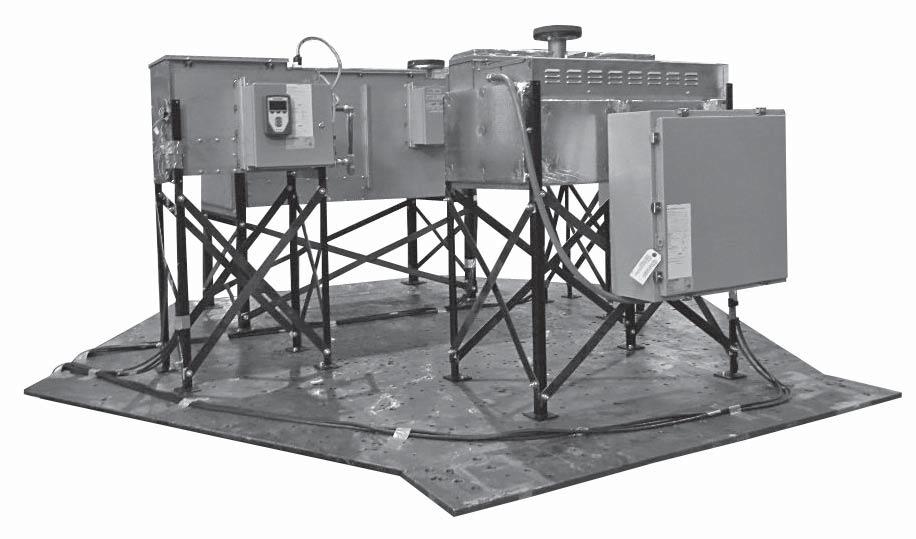
6 STS-200 THROUGH STS-800 STS-200 through STS-800 fl oor mount installation drawing Refer to the STS IOM for all other installation, operation, and maintenance instructions. Complete the seismic installation as shown in Figure 4-1 and the installation steps on the next page. FIGURE 4-1: STS-200 THROUGH STS-800 FLOOR MOUNT SEISMIC CERTIFICATION OPTION INSTALLATION Crossbrace Length in mm Front/Rear, STS /4 857 Side, STS / /8" x 3" Bolt 3/8" Nut (8) (16) See Detail A 3/8" Nut 3/8" x 3" Bolt (8) Legs (16) (16) 3/8" Nut (8) Spacer (24) See Detail B 3/8" x 3-1/2" Bolt (8) Detail A (Top View) 3/8" x 3-1/2" Bolt (16) Spacers (3) Side cross braces 3/8" Nut Legs Front/rear cross braces (8) 3/8" Minimum grade 2 bolts. Refer to Anchorage details supplied by the Structural Engineer of Record. Detail B (Top View) Notes: 1. The height from floor to bottom of tank is 23 7/8 in (606 mm). 2. All hardware shown supplied by DriSteem. DM
7 STS-200 THROUGH STS-800 STS-200 through STS-800 fl oor mount installation steps 1. Attach legs to tank assembly. See Detail A in Figure 4-1. a. Use supplied 3/8" x 3" bolts to attach leg weldments to tank. Use both bolt locations on all legs. b. Leave these bolts loose until after cross braces are completely assembled and tightened in step Attach cross-braces to legs. See Detail B in Figure 4-1. a. Use supplied 3/8" x 31/2" bolts to attach cross braces to legs as shown. Use three square spacers on each side of the outer cross braces to prevent bending. b. Torque all cross-brace bolts to 30 ft-lbs (40 N-m). 3. Torque all leg bolts to 30 ft-lbs (40 N-m). 4. Attach legs to support structure using all eight bolt hole locations and in accordance to instructions by the Structural Engineer of Record. 5. Refer to the STS IOM for all other installation, operation, and maintenance instructions. 5
8 VAPORSTREAM Vaporstream: Floor mount installation drawing Refer to the Vaporstream IOM for all other installation, operation, and maintenance instructions. Complete the seismic installation as shown in Figure 6-1 and the installation steps on the next page. FIGURE 6-1: VAPORSTREAM FLOOR MOUNT SEISMIC CERTIFICATION OPTION INSTALLATION Crossbrace in Length mm Front/Rear, all sizes 33 1/8 841 Side, 1 heater 28 1/4 717 Side, 3 heater 29 3/4 755 Side, 6 heater Side, 9 heater 33 1/4 844 Side, 12 heater 43 7/ Front 1/4" Nut (12) 1/4" Washer 1/4" Nut See detail A 1/4" Washer 1/4" Washer (24) 1/4" Bolt (12) See detail B 1/4" Bolt Detail A (top view) Spacer (8) 3/8" Bolt 3/8" Bolt (32) Spacer "R" 3/8" Nut (16) (32) "L" "L" Side cross braces 3/8" Nut Front/rear cross braces "R" (4) 3/8" Minimum grade 2 bolts. Refer to Anchorage details supplied by the Structural Engineer of Record. Detail B (top view) Notes: 1. The two leg weldments with "R" marked on the bottom of the feet are used in these locations. Holding the leg weldments so that the angle iron is in the shape of an L when looking at it from the top, these have the fourth hole closer to the third hole on the vertical part of the L. 2. The height from floor to bottom of tank is 30 ½ in (774 mm). 3. All hardware shown supplied by DriSteem. DM
9 VAPORSTREAM Vaporstream: Floor mount installation steps 1. Attach legs to tank assembly - See Detail A in Figure 6-1. a. Vaporstream with remote control cabinet - identify Front Right and Back Left leg weldments. Side of the tank with drain assembly and clean-out plate is front. Weldments marked "L" on the bottom of feet are used in Front Left and Back Right locations. Use 1/4"-20 x 1¼" bolts to attach leg weldments to tank. Use all three bolt locations on all legs. Leave these bolts loose until after cross braces are completely assembled and tightened (Step 2). b. Vaporstream with control cabinet factory mounted on humidifier - identify Front Right and Back Left leg weldments. Side of the tank with drain assembly and clean-out plate is considered front. See figure 6-1 for front view callout. Callout will help orientation during installation. Remove the control cabinet from tank and support it within range of motion the flexible conduit allows. Two weldments, marked "L" on the bottom of feet, are used in Front Left and Back Right locations. Use included 1/4-20 x 1¼ bolts to attach leg weldments to tank. Use all three bolt locations on all legs. Note: Available space between control cabinet brackets and tank flange is tight. It is recommended to insert bolts and washers though the holes in leg assembly and tape them in place before assembling them to tank. Once washers and nuts are started on bolts, tape can be removed. Leave bolts loose until after cross braces are completely assembled and tightened (Step 2). 2. Attach cross-braces to legs - See Detail B in Figure 6-1. a. Use square spacers on one of each side's set of cross-braces. Vaporstream with control cabinet factory mounted on humidifier: Attach the cross-braces on the control cabinet side. Attach cross-braces to legs. Depending on tank and control cabinet size there may be slots in the control cabinet support brackets. Insert cross-braces through slots. Torque all cross brace bolts to 30 ft-lbs (40.7 N-m). Replace control cabinet onto tank. 3. Torque all leg bolts to 8 ft-lbs (10.8 N-m). 4. Attach legs to support structure using all four bolt hole locations and in accordance with instructions by the Structural Engineer of Record. 7
10 VAPORSTREAM Vaporstream: Weather cover installation drawing in this manual and to a structurally stable surface. Improper mounting of the humidifier can cause it to fall or to tip, resulting in severe personal injury Refer to the Vaporstream IOM for all other installation, operation, and maintenance instructions. Complete the seismic installation as shown in Figure 8-1. FIGURE 8-1: VAPORSTREAM WEATHER COVER SEISMIC CERTIFICATION OPTION INSTALLATION Vaporstream weather cover (4) 3/8" Minimum grade 2 bolts. Refer to anchorage details supplied by the Structural Engineer of Record. DM
11 VAPORMIST Vapormist: Wall mount installation drawing Refer to the Vapormist IOM for all other installation, operation, and maintenance instructions. Complete the seismic installation as shown in Figure 9-1. FIGURE 9-1: VAPORMIST SEISMIC CERTIFICATION OPTION WALL MOUNT INSTALLATION 16" (406 mm) 3" (76 mm) Mounting hardware to be (two) 3/8" DIA grade 2 minimum bolts with washers, lock washers, and nuts. Refer to the anchorage details supplied by the Structural Engineer of Record. 18.5" (470 mm) Vapormist chassis DM " (609 mm) 9
12 MINI-BANK Mini-bank: Installation drawing in an air handling unit Refer to the Steam Injection IOM for all other installation, operation, and maintenance instructions. Complete the seismic installation as shown in Figure FIGURE 10-1: MINI-BANK SEISMIC CERTIFICATION OPTION INSTALLATION IN AN AIR HANDLING UNIT A-A See inset A-A at right AHU wall Section A-A 1/4" thick angle A-A 3/8" Grade 5 bolt (TYP) 1/4" thick angle (2) 1-5/8" Square unistrut-12 gauge 1/4" thick angle #10-32 Bolts, washers, and nuts (TYP) B See inset B-B at right Typical Mini-bank B 1/4" Self tap screws 1/4" thick angle (3) 1-5/8" Square unistrut-12 gauge 3/8" Grade 5 bolt (TYP) AHU floor Section B-B 3/4" Strut conduit clamp (TYP) DM
13 MINI-BANK Mini-bank: Installation drawing in a duct Refer to the Steam Injection IOM for all other installation, operation, and maintenance instructions. Complete the seismic installation as shown in Figure FIGURE 11-1: MINI-BANK SEISMIC CERTIFICATION OPTION INSTALLATION IN A DUCT Duct width Duct 1/2" NPT (DN15) connection 1.5" (38 mm) Duct height Valve Separator (M5) tapped hole. Attach dispersion end to duct with bolts, washers, and nuts. Dispersion tubes 1/2" NPT (DN15) connection 1/2" NPT (DN15) inlet Escutcheon plates fit around tubes DM
14 ULTRA-SORB Ultra-sorb: Model LV Installation drawing in an air handling unit Refer to the Ultra-sorb Models LV and LH IOM for all other installation, operation, and maintenance instructions. Complete the seismic installation as shown in Figure FIGURE 12-1: ULTRA-SORB MODEL LV SEISMIC CERTIFICATION OPTION INSTALLATION IN AN AIR HANDLING UNIT See inset A-A at right A A AHU Roof 3/8" Grade 5 bolt (3) 1/4" Thick angle Section A-A 1-5/8" Square unistrut - 12 gauge Airflow 3/8" Grade 5 steel bolt with backup washers (both sides) 1-5/8" Square unistrut - 12 gauge 6" (152 mm) Max 1/4" Self tap screw (3) 1/4" Thick angle (3) 3/8" Grade 5 bolt (2) AHU floor Section B-B Typical Ultra-sorb LV B B See inset B-B at right DM
15 ULTRA-SORB Ultra-sorb: Model LV Installation drawing in a duct Refer to the Ultra-sorb Models LV and LH IOM for all other installation, operation, and maintenance instructions. Complete the seismic installation as shown in Figure FIGURE 13-1: ULTRA-SORB MODEL LV SEISMIC CERTIFICATION OPTION INSTALLATION IN A DUCT A matching flange or metal frame is required on the ductwork for connection to the Ultrasorb flanges. 1/4" Grade 5 bolt, washers, and nuts. 6" (152 mm) (max) spacing on both left and right side of Ultra-sorb. 1/4" - 20 Self drill/tap sheet metal screws. 6" (152 mm) (max) spacing on both top and bottom of Ultra-sorb. Note: To avoid damaging the header, screws and drill bits must not penetrate more than 3/4" (20 mm) into the header assembly. DM
16 ULTRA-SORB Ultra-sorb: Model LH Installation drawing in an air handling unit in this manual and to a structurally stable surface. Improper mounting of the humidifier can cause it to fall or to tip, resulting in severe personal injury Refer to the Ultra-sorb Models LV and LH IOM for all other installation, operation, and maintenance instructions. Complete the seismic installation as shown in Figure FIGURE 14-1: ULTRA-SORB MODEL LH SEISMIC CERTIFICATION OPTION INSTALLATION IN AN AIR HANDLING UNIT See inset A-A at right A A AHU Roof 3/8" Grade 5 steel bolt with backup washers (6) 3/8" Grade 5 bolt (3) Section A-A 1/4" Thick Angle 1-5/8" Square unistrut - 12 gauge Airflow 1-5/8" Square unistrut - 12 gauge 1/4"Self tap screw (3) 1/4" Thick angle (3) 3/8" Grade 5 bolt (2) AHU floor Section B-B Typical Ultra-sorb LH B B See inset B-B at right DM
17 ULTRA-SORB Ultra-sorb: Model LH Installation drawing in a duct Refer to the Ultra-sorb Models LV and LH IOM for all other installation, operation, and maintenance instructions. Complete the seismic installation as shown in Figure Note: For Model LH, seismic certification is only available with horizontal airflow. stable surface. Improper mounting of the humidifier can cause it to fall or to tip, resulting in severe personal injury FIGURE 15-1: ULTRA-SORB MODEL XV SEISMIC CERTIFICATION OPTION INSTALLATION IN A DUCT A matching flange or metal frame is required on the ductwork for connection to the Ultrasorb flanges. 1/4" Grade 5 bolt, washers, and nuts. 6" (152 mm) (max) spacing on both left and right side of Ultra-sorb. 1/4" - 20 Self drill/tap sheet metal screws. 6" (152 mm) (max) spacing on both top and bottom of Ultra-sorb. Note: To avoid damaging the header, screws and drill bits must not penetrate more than 3/4" (20 mm) into the header assembly. DM
18 ULTRA-SORB Ultra-sorb: Model XV Installation drawing in an air handling unit in this manual and to a structurally stable surface. Improper mounting of the humidifier can cause it to fall or to tip, resulting in severe personal injury Refer to the Ultra-sorb Model XV IOM for all other installation, operation, and maintenance instructions. Complete the seismic installation as shown in Figure FIGURE 16-1: ULTRA-SORB MODEL XV SEISMIC CERTIFICATION OPTION INSTALLATION IN AN AIR HANDLING UNIT See inset A-A at right A A AHU Roof Section A-A 3/8" Grade 5 bolt (3) 1/4" Thick angle 1-5/8" Square unistrut - 12 gauge Airflow 3/8" Grade 5 steel bolt with backup washers (both sides) 1/4" Self tap screw (3) 1/4" Thick angle (3) 1-5/8" Square unistrut - 12 gauge 3/8" Grade 5 bolt (2) 6" (152 mm) Max AHU floor Section B-B Typical Ultra-sorb XV B B See inset B-B at right DM
19 ULTRA-SORB Ultra-sorb: Model XV Installation drawing in a duct Refer to the Ultra-sorb Model XV IOM for all other installation, operation, and maintenance instructions. Complete the seismic installation as shown in Figure FIGURE 17-1: ULTRA-SORB MODEL XV SEISMIC CERTIFICATION OPTION INSTALLATION IN A DUCT A matching flange or metal frame is required on the ductwork for connection to the Ultra-sorb flanges. 1/4" Grade 5 bolt, washers, and nuts. 6" (152 mm) (max) spacing on both left and right side of Ultra-sorb. 1/4" - 20 Self drill/tap sheet metal screws. 6" (152 mm) (max) spacing on both top and bottom of Ultra-sorb. Note: To avoid damaging the header, screws and drill bits must not penetrate more than 3/4" (20 mm) into the header assembly. DM
20 Expect quality from the industry leader Since 1965, DriSteem has led the industry with innovative methods for humidifying and cooling air with precise control. Our focus on ease of ownership is evident in the design of the Wetted Media System. DriSteem also leads the industry with a Two-year Limited Warranty and optional extended warranty. For more information sales@dristeem.com For the most recent product information visit our website: DRI-STEEM Corporation a subsidiary of Research Products Corporation DriSteem is an ISO 9001:2000 certifi ed company U.S. Headquarters: Technology Drive Eden Prairie, MN or (fax) European offi ce: Grote Hellekensstraat 54 b B-3520 Zonhoven Belgium dristeem-europe@dristeem.com Continuous product improvement is a policy of DriSteem; therefore, product features and specifi cations are subject to change without notice. DriSteem, STS, Ultra-sorb, Vapor-logic, Vapormist, and Vaporstream are registered trademarks of Research Products Corporation and are fi led for trademark registration in Canada and the European community. Product and corporate names used in this document may be trademarks or registered trademarks. They are used for explanation only without intent to infringe Research Products Corporation TWO-YEAR LIMITED WARRANTY DRI-STEEM Corporation ( DriSteem ) warrants to the original user that its products will be free from defects in materials and workmanship for a period of two (2) years after installation or twenty-seven (27) months from the date DriSteem ships such product, whichever date is the earlier. If any DriSteem product is found to be defective in material or workmanship during the applicable warranty period, DriSteem s entire liability, and the purchaser s sole and exclusive remedy, shall be the repair or replacement of the defective product, or the refund of the purchase price, at DriSteem s election. DriSteem shall not be liable for any costs or expenses, whether direct or indirect, associated with the installation, removal or reinstallation of any defective product. The Limited Warranty does not include cylinder replacement for electrode steam humidifiers or media replacement for Wetted Media Systems. DriSteem s Limited Warranty shall not be effective or actionable unless there is compliance with all installation and operating instructions furnished by DriSteem, or if the products have been modified or altered without the written consent of DriSteem, or if such products have been subject to accident, misuse, mishandling, tampering, negligence or improper maintenance. Any warranty claim must be submitted to DriSteem in writing within the stated warranty period. Defective parts may be required to be returned to DriSteem. DriSteem s Limited Warranty is made in lieu of, and DriSteem disclaims all other warranties, whether express or implied, including but not limited to any IMPLIED WARRANTY OF MERCHANTABILITY, ANY IMPLIED WARRANTY OF FITNESS FOR A PARTICULAR PURPOSE, any implied warranty arising out of a course of dealing or of performance, custom or usage of trade. DriSteem SHALL NOT, UNDER ANY CIRCUMSTANCES BE LIABLE FOR ANY DIRECT, INDIRECT, INCIDENTAL, SPECIAL OR CONSEQUENTIAL DAMAGES (INCLUDING, BUT NOT LIMITED TO, LOSS OF PROFITS, REVENUE OR BUSINESS) OR DAMAGE OR INJURY TO PERSONS OR PROPERTY IN ANY WAY RELATED TO THE MANUFACTURE OR THE USE OF ITS PRODUCTS. The exclusion applies regardless of whether such damages are sought based on breach of warranty, breach of contract, negligence, strict liability in tort, or any other legal theory, even if DriSteem has notice of the possibility of such damages. By purchasing DriSteem s products, the purchaser agrees to the terms and conditions of this Limited Warranty. EXTENDED WARRANTY The original user may extend the term of the DriSteem Limited Warranty for a limited number of months past the initial applicable warranty period and term provided in the first paragraph of this Limited Warranty. All the terms and conditions of the Limited Warranty during the initial applicable warranty period and term shall apply during any extended term. An extended warranty term of an additional twelve (12) months or twenty four (24) months of coverage may be purchased. The extended warranty term may be purchased until eighteen (18) months after the product is shipped, after which time no extended warranties are available. Any extension of the Limited Warranty under this program must be in writing, signed by DriSteem, and paid for in full by the purchaser. mc_051308_0630 Form No. SEISMIC-IOM-EN-0615 Part No Rev B
Drag Chain Conveyor Installation and Operation Manual
 Drag Chain Conveyor Installation and Operation Manual Material Handling Equipment Sales, Incorporated 310 S. Section Line Rd Delaware, OH 43015 Phone: (989) 430-4005 Fax: (740) 363-9004 WARRANTY MATERIAL
Installation Guide Document No Transaction Windows Copyright 2017 Terra Universal Inc. All rights reserved. Revised October 2017
 Installation Guide Document No. 1788-01 Copyright 2017 Terra Universal Inc. All rights reserved. Revised October 2017 Terra Universal, Inc. TerraUniversal.com 800 S. Raymond Ave. Fullerton, CA 92831 TEL:
RHE3 Dock Leveler Installation Manual
 RHE3 Dock Leveler Installation Manual MADE IN U.S.A. This Manual Covers Dock Levelers Built After Serial Numbers: 07FE160001M and up PRINTED IN U.S.A. RITE-HITE PRINT SHOP PUBLICATION NO. 1222 MAY 2007
PS-31 (SUS304, 300 mm) PS-31 (SUS304, 1,000 mm)
 PS-31 (SUS304, 1,000 mm)") CSM_PS-_S(R)_-31_DS_E_7_1 Separate s for Water Supply and Drainage Control in Buildings. Small, Lightweight s for Use as Built-in Components. The PS-@S(R) are separate s that allow the s to be withdrawn
CSM_PS-_S(R)_-31_DS_E_7_1 Separate s for Water Supply and Drainage Control in Buildings. Small, Lightweight s for Use as Built-in Components. The PS-@S(R) are separate s that allow the s to be withdrawn
General Guidelines. Tools Required. Instructions for Part # SC500-AF. Safety
 Instructions for Part # SC500-AF General Guidelines It is the user s responsibility to read and follow all instructions. Keep these instructions with the product at all times and review before each use.
FORM HEADWALL. FORM HEADWALL (floating) (floating) Installation Manual
 (floating) Installation Manual") FORM HEADWALL (floating) Installation Manual FORM HEADWALL (floating) OVERVIEW The Form is a UL-listed configurable headwall system. This system includes multiple horizontal equipment channels integrated
FORM HEADWALL (floating) Installation Manual FORM HEADWALL (floating) OVERVIEW The Form is a UL-listed configurable headwall system. This system includes multiple horizontal equipment channels integrated
DRYWALL DOLLY 900 LB. CAPACITY
 DRYWALL DOLLY 900 LB. CAPACITY 94883 ASSEMBLY & OPERATING INSTRUCTIONS Due to continuing improvement, actual product may differ slightly from the product described herein. 3491 Mission Oaks Blvd., Camarillo,
Fig. 1 - Standard Clevis Hanger
 Revision 10/24/2007 Fig. 1 - Standard Clevis Hanger Component of State of California OSHPD Approved Seismic Restraints System Size Range Size 1/2" thru 36" pipe. Function Recommended for the suspension
Owner s Manual Shelf Lip Accessory
 Owner s Manual Shelf Lip Accessory Full Length Shelf Lip Half Length Shelf Lip CONTENTS Safety...................................................................2 General..............................................................2
INSTALLATION PROCEDURE
 INSTALLATION PROCEDURE VOLU-probe/1SS for Round Ducts WARRANTY Air Monitor Corporation (hereinafter referred to as "Seller") warrants that at the time of shipment, products sold pursuant to this contract
Tourmaster 3-Step Riser
 Assembly Manual Tourmaster 3-Step Riser Note: Shade variations may be present from step to step due to the nap of the carpet. contents Safety Precautions.................................. Warranty..........................................
SECTION HANGERS AND SUPPORTS FOR ELECTRICAL SYSTEMS
 SECTION 26 05 29 HANGERS AND SUPPORTS FOR ELECTRICAL SYSTEMS PART 1 GENERAL 1.1 DESCRIPTION A. Scope: 1. CONTRACTOR shall provide all labor, materials, equipment, and incidentals as shown, specified, and
Switch-Tek. LV41 & LV42 Series Manual. Sump Float Level Switches
 Switch-Tek Sump Float Level Switches LV41 & LV42 Series Manual LV41 Series Shown LV42 Series Shown Flowline, Inc. 10500 Humbolt Street, Los Alamitos, CA 90720 p 562.598.3015 f 562.431.8507 w flowline.com
BIN LINER INSTALLATION MANUAL IMPORTANT!
 BIN LINER INSTALLATION MANUAL IMPORTANT! Bins with 44 seam spacing require drilling of the liner and the bin & additional rows of bolts between existing seam rows. CAUTION Edges may be sharp, wear gloves
Quick-Start Operating Guide Document No Process Gas Cooler Copyright 2010 Terra Universal Inc. All rights reserved. Revised October 2010
 Document No. 1800-56 Copyright 2010 Terra Universal Inc. All rights reserved. Revised October 2010 Terra Universal, Inc. TerraUniversal.com 800 S. Raymond Ave. Fullerton, CA 92831 TEL: (714) 578-6000 FAX:
Installation and Operation Manual
 Installation and Operation Manual Maintenance Bypass Panel Model: SU2030KMBP Tripp Lite follows a policy of continuous improvement. Product specifications are subject to change without notice. 1111 West
Fig Beam Clamp Retaining Strap (B-Line B3367)
") Fig. 69 - Beam Clamp Retaining Strap (B-Line B3367) Size Range: 3 /8"-16 thru 3 /4"-10 rod 4 (101.6mm) thru 16 (406.4mm) lengths Note: longer lengths are available consult factory Material: Pre-Galvanized
Fig. 69 - Beam Clamp Retaining Strap (B-Line B3367) Size Range: 3 /8"-16 thru 3 /4"-10 rod 4 (101.6mm) thru 16 (406.4mm) lengths Note: longer lengths are available consult factory Material: Pre-Galvanized
Owner s Manual & Safety Instructions
 Owner s Manual & Safety Instructions Save This Manual Keep this manual for the safety warnings and precautions, assembly, operating, inspection, maintenance and cleaning procedures. Write the product s
Protective Capony RTC-16
 Protective Capony RTC-16 ASSEMBLY AND OPERATION MANUAL Protective Canopy RTC-16 Assembly and Operation Manual CONTENT: 1 APPLICATION...3 2 OPERATION CONDITIONS...3 3 TECHNICAL SPECIFICATIONS...3 4 DELIVERY
Owner s Manual & Safety Instructions
 Owner s Manual & Safety Instructions Save This Manual Keep this manual for the safety warnings and precautions, assembly, operating, inspection, maintenance and cleaning procedures. Write the product s
SGLP-RO. Installation and Operating Instructions for SCALEGARD TM LP REVERSE OSMOSIS FILTRATION SYSTEM. 3M TM Water Filtration Products
 3M TM Water Filtration Products Installation and Operating Instructions for SCALEGARD TM LP REVERSE OSMOSIS FILTRATION SYSTEM SGLP-RO Installer: Please leave this manual with owner/operator. LIMITED WARRANTY
SHCM SHOWER COLUMN INSTALLATION INSTRUCTIONS
 SHCM-27180 SHOWER COLUMN INSTALLATION INSTRUCTIONS IMPORTANT DreamLine TM reserves the right to alter, modify or redesign products at any time without prior notice. For the latest up-to-date technical
Maintenance Bypass Breaker Cabinet Series Configuration 5. Installation and Operation Manual
 Maintenance Bypass Breaker Cabinet 90881 Series Configuration 5 Installation and Operation Manual 03/13/2012 2 755-00084-C5 R03 Copyright 2012 C&C Power, Inc. All rights reserved. C&C Power, Inc. 395 Mission
Sby SR Instruments, Inc.
 Part No.: MAN947IFS_170629 Page 1 of 12 Sby SR Instruments, Inc. SRV947IFS REMOTE DISPLAY PLATFORM SCALE Operating and Service Manual Part No.: MAN947IFS_170629 Page 2 of 12 TABLE OF CONTENTS TABLE OF
C60 Standby UPS. 800VA Models. User & Installation Manual Xtreme Power Conversion Corporation. All rights reserved.
 For more information, visit www.247technology.com/on-line-ups/c60-standby-ups C60 Standby UPS 800VA Models User & Installation Manual 2015. All rights reserved. (Rev 6/23/15) Table of Contents Package
Bed Docker. Installation Manual. Model BD 600/601
 Bed Docker Installation Manual Bed Docker Model BD 600/601 Overview The Modular Services Bed Docker provides a docking location for the patient bed with connections for electrical devices on each side.
LOAD RAMP 1000 LB. CAPACITY
 LOAD RAMP 1000 LB. CAPACITY 55424 ASSEMBLY AND OPERATING INSTRUCTIONS Safely roll Dirt Bikes and more into your Pickup! 3491 Mission Oaks Blvd., Camarillo, CA 93011 Visit our Web site at http://www.harborfreight.com
Installation Guide April 2017
 Installation Guide April 207 3M Fire and Water Barrier Tape Installation: Wall to wall Install mineral wool into the straight wall to wall gap. Peel back one corner of the liner to expose tape and adhere
BUSWAY LOW VOLTAGE (POW-R-WAY III) SECTION SECTION 16466
 SECTION SECTION 16466") BUSWAY LOW VOLTAGE (POW-R-WAY III) PART 1 GENERAL 1.01 1.02 SCOPE The Contractor shall furnish and install the busway system including all necessary fittings, hangers and accessories as specified herein
BUSWAY LOW VOLTAGE (POW-R-WAY III) PART 1 GENERAL 1.01 1.02 SCOPE The Contractor shall furnish and install the busway system including all necessary fittings, hangers and accessories as specified herein
END TRUCKS WHEEL SIZES: 9", 12", 15" & 18"
 OPERATION, SERVICE & PARTS MANUAL STRUCTURAL TUBE ROTATING AXLE WHEEL SIZES: 9", ", 5" & 8" P/N: 5367 REV. AA November 03 ROTATING TOP AXLE RUNNING END ROTATING TRUCK PARTS AXLE BREAKDOWN END TRUCK P/N:
SECTION SEISMIC CONTROL OSHPD
 SECTION 01451 PART 1 - GENERAL 1.01 DESCRIPTION A. Provide all required seismic restraints and calculations in order to insure that the installation of all architectural, mechanical, and electrical equipment/components
MASTER. Water Conditioning Corp. OPERATION MANUAL. PURO PRO 1200 SCP Series Modular Reverse Osmosis System. January 2012 Version
 MASTER Water Conditioning Corp. www.masterwater.com OPERATION MANUAL PURO PRO 1200 SCP Series Modular Reverse Osmosis System January 2012 Version Table of Contents Model Number... 1 Shipping Description
Owner s Manual & Safety Instructions
 Owner s Manual & Safety Instructions Save This Manual Keep this manual for the safety warnings and precautions, assembly, operating, inspection, maintenance and cleaning procedures. Write the product s
Troubleshooting Guide 9702 Series
 Troubleshooting Guide 9702 Series Satellite Solutions for Mobile Markets 11200 Hampshire Avenue South, Bloomington, MN 55438-2453 Phone: (800) 982-9920 Fax: (952) 922-8424 www.kingcontrols.com 1305-AUTO
Daniel TM Ultrasonic Flow Meters
 Installation and Operating Instructions Manual Part Number 3-9000-745 Revision F August 2017 Daniel TM Ultrasonic Flow Meters Installation and Operating Instructions Specific to the Pressure Equipment
Series 5500 Bellows Pump Connectors Catalog 474E
 Series 5500 Bellows Pump Connectors Catalog 474E Series 5500 Bellows Pump Connectors Sizes 1-1 /2 through 24 Design Conditions: full vacuum to 150 and 300 psig at 500 F Compact design with maximum flexibility
4 rotary milling table
 4 rotary milling table Model 97208 Set up And Operating Instructions Diagrams within this manual may not be drawn proportionally. Due to continuing improvements, actual product may differ slightly from
Installation Instructions
 Installation Instructions Dynarail Safety Ladder System Corrosion Resistant Nonconductive Fire Retardant High Strength-To-Weight Ratio Long, Low Maintenance Life Meets OSHA, BOCA & Other Building Code
TOLCO Fire Protection Support Systems. Pipe Hangers Supports Seismic Bracing. UL Listed FM Approved for Fire Sprinkler Installations
 TOLCO Fire Protection Support Systems Pipe Hangers Supports Seismic Bracing UL Listed FM Approved for Fire Sprinkler Installations Revision 12/06/2007 Catalog Forward This catalog has been created with
Owner s Manual Full Motion Flat Screen Wall Mount
 Owner s Manual Full Motion Flat Screen Wall Mount MODEL: DWM2655M CAUTION: DO NOT EXCEED MAXIMUM LISTED WEIGHT CAPACITY. SERIOUS INJURY OR PROPERTY DAMAGE MAY OCCUR! 200x200/300x300/ 400x200/400x400 55
Model # 358H-PR. 4/8/2011 Page 1 of 12
 Model # 358H-PR 4/8/2011 Page 1 of 12 4/8/2011 Page 2 of 12 1675 Locust Street Red Bud, IL 62278 Phone: 618-282-8200 Fax: 618-282-8202 WARRANTY & TERMS WARRANTY: 5 Year Limited Warranty on Thermoplastic
Precision Automatic Vacuum Control (PAVC+)
") USER GUIDE UGE105-1216 www.conairgroup.com Precision Automatic Vacuum Control (PAVC+) Corporate Office: 724.584.5500 l Instant Access 24/7 (Parts and Service): 800.458.1960 l Parts and Service: 814.437.6861
USER GUIDE UGE105-1216 www.conairgroup.com Precision Automatic Vacuum Control (PAVC+) Corporate Office: 724.584.5500 l Instant Access 24/7 (Parts and Service): 800.458.1960 l Parts and Service: 814.437.6861
MASTER. Water Conditioning Corp. OPERATION MANUAL. PURO PRO 1200 SC Series Modular Reverse Osmosis System. January 2012 Version
 MASTER Water Conditioning Corp. www.masterwater.com OPERATION MANUAL PURO PRO 1200 SC Series Modular Reverse Osmosis System January 2012 Version Table of Contents Model Number... 1 Shipping Description
1 TON PORTABLE GANTRY CRANE Model LB. PORTABLE GANTRY CRANE Model 94831
 1 TON PORTABLE GANTRY CRANE Model 94884 660 LB. PORTABLE GANTRY CRANE Model 94831 ASSEMBLY AND OPERATING INSTRUCTIONS Due to continuing improvements, actual products may differ slightly from the products
Aero Tec Models 700 & 750 (115 vac)
") Aero Tec Installation Guide Aero Tec Models 700 & 750 (115 vac) A Product of 340 Gateway Park Drive North Syracuse, NY 13212 Phone: 315-463-7348 Toll Free: 866-235-7468 Fax: 315-463-8559 Email: sales@dlmanufacturing.com
Aero Tec Installation Guide Aero Tec Models 700 & 750 (115 vac) A Product of 340 Gateway Park Drive North Syracuse, NY 13212 Phone: 315-463-7348 Toll Free: 866-235-7468 Fax: 315-463-8559 Email: sales@dlmanufacturing.com
Vision Platform System
 Owner s Manual Vision Platform System CONTENTS Safety Precautions.................................. 2 Setup........................................ 2 Guard Rails.................................... 2 Transport/Storage
5. AMCA 301 Method of Publishing Sound Ratings for Air Moving Devices. 6. AMCA 500 Test Methods for Louver, Dampers, and Shutters
 PART 1: GENERAL 1.01 Purpose: A. This standard is intended to provide useful information to the Professional Service Provider (PSP) to establish a basis of design. The responsibility of the engineer is
INSTALLATION PROCEDURE
 INSTALLATION PROCEDURE ELECTRA-flo/FI INSPECTION & HANDLING. The ELECTRA-flo/FI should be carefully inspected for damage prior to installation. Report damage to your Freight Department, or contact delivery
PEN SEAL. Pipe Penetration Seals
 PEN SEAL Pipe Penetration Seals PROCO s Pipe Penetration Seals have been designed to assist in achieving an efficient, low-cost mechanical seal between any Electrical Conduit, Concrete, Cast Iron, Steel,
7 PIECE TUBE FLARING KIT
 7 PIECE TUBE FLARING KIT Model 5969 Set up And Operating Instructions Diagrams within this manual may not be drawn proportionally. Due to continuing improvements, actual product may differ slightly from
Owner s Manual Full Motion Flat Screen Wall Mount
 Owner s Manual Full Motion Flat Screen Wall Mount MODEL: DWM3770X CAUTION: DO NOT EXCEED MAXIMUM LISTED WEIGHT CAPACITY. SERIOUS INJURY OR PROPERTY DAMAGE MAY OCCUR! 200x200/300x300/ 400x200/400x400/ 600x400
Installation. Basic Rack Power Distribution Units AP9560 AP9561
 Installation Basic Rack Power Distribution Units AP9560 AP9561 Contents Preliminary Information...................1 AP9560...........................1 AP9561...........................1 Safety and Grounding....................2
PIP PCEPA003 Process Analyzer System Field Installation Guidelines
 January 2016 Process Control PIP PCEPA003 Process Analyzer System Field Installation Guidelines PURPOSE AND USE OF PROCESS INDUSTRY PRACTICES In an effort to minimize the cost of process industry facilities,
B-500 / B-600 SERIES
 B-500 / B-600 SERIES VAPOR VENT TRANSITION INSTALLATION GUIDE SINGLE WALL VENT TRANSITION SUMPS B-500 VENT TRANSITION SINGLEWALL SERIES SHOWN WITH WATERSPLASH LID, AND SUPPORT FOR 5 VENT LINES. B-500 SINGLEWALL
This Installation Guide uses the following symbols to indicate important information. Always observe the instructions indicated by these symbols.
 VIGO INDUSTRIES INSTALLATION GUIDE FOR STANDING SHOWER CABIN (MODEL VG06062) SAFETY PRECAUTIONS This Installation Guide uses the following symbols to indicate important information. Always observe the
Suspension System Data Center Ceiling Solutions
 Hardware That Needs to be Purchased Separately Screws are fine listed as shown: Min 1-1/4" or longer #8 Truss head self-tapping screws for attaching structural wall angle, lateral support bar 16" or 4"
TOLL FREE: (866) VANITY SPECIFICATIONS. VANITY COMPONENTS Model VG09008
 VANITY SPECIFICATIONS. VANITY COMPONENTS Model VG09008") VANITY SPECIFICATIONS VANITY COMPONENTS Model VG09008 MODEL VG09008 FEATURES Wall-mounted cabinet Soft closing sliding cabinet drawer hardware Cabinet ships assembled PACKING LIST Vanity Brackets - 2 Plastic
VANITY SPECIFICATIONS VANITY COMPONENTS Model VG09008 MODEL VG09008 FEATURES Wall-mounted cabinet Soft closing sliding cabinet drawer hardware Cabinet ships assembled PACKING LIST Vanity Brackets - 2 Plastic
VISE MOUNTED. Model 97359
 VISE MOUNTED Small English wheel Model 97359 Set up And Operating Instructions Diagrams within this manual may not be drawn proportionally. Due to continuing improvements, actual product may differ slightly
ROOF MOUNT KIT OWNERS MANUAL
 ROOF MOUNT KIT OWNERS MANUAL Made in the USA by: Primus Wind Power, Inc. 938 Quail St. Lakewood, CO 80215 Phone: (303) 242-5820 www.primuswindpower.com AIR is a trademark of Primus Wind Power, Inc. ROOF
Standard Duty Cantilever Rack Installation and Assembly Guide
 Standard Duty Cantilever Rack Installation and Assembly Guide Steel King Industries, Inc. 2700 Chamber St Stevens Pont, WI 54481 (800) 826 0203 www.steelking.com info@steelking.com ASSEMBLY INSTRUCTIONS:
MERCEDES SPRINTER PARTITION INSTALLATION INSTRUCTIONS
 www.sortimo.knapheide.com Document # 3964-01 The following instructions detail the procedure for installing a Sortimo By Knapheide Protexx Partition in a Mercedes Sprinter. This guide is intended to walk
PS-4045 Adjustable-Height Pallet Stand Use and Maintenance Manual
 Vestil Manufacturing Co. 2999 North Wayne Street, P.O. Box 507, Angola, IN 46703 Telephone: (260) 665-7586 -or- Toll Free (800) 348-0868 Fax: (260) 665-339 http://www.vestilmfg.com/ e-mail: sales@vestil.com
Seismic Installation Manual
 Seismic Installation Manual California Office of Statewide Health Planning & Development OPA-2123-10 This manual provides the design strength capacities and installation guidelines for the Bracing System
A-Series Aluminum Gantry Crane
 SPANCO PRODUCT SPECIFICATIONS 1 A-Series Aluminum Gantry Crane This guide can be used to prepare a bid specification for the incorporation of an A-Series Gantry Crane into a competitive bid project or
Adjustable Fused Power Supply
 User & Installation Manual EN Adjustable Fused Power Supply 7-20V 3A P010-52 Contact & Product mo-vis BVBA Biebuyckstraat 15 D 9850 Nevele - Belgium Website: www.mo-vis.com E-mail: contact@mo-vis.com Telephone:
Read and understand this manual for safely usage.
 Read and understand this manual for safely usage. This manual describes the product of standard specification. Read the other manual for the product of explosion-proof specification. This manual describes
SECTION 5 E-Treat Water Conditioning Systems
 SECTION 5 E-Treat Water Conditioning Systems WaTEr QualITy PrOduCTS Catalog 10 Watts product specifications in U.S. customary units and metric are approximate and are provided for reference only. Watts
Insulated Fire-Rated Access Door Model(s): BIT/BIW/BIP
: BIT/BIW/BIP") Insulated Fire-Rated Access Door INSTALLATION, OPERATION & MAINTENANCE MANUAL Table of Contents Insulated Fire-Rated Access Door Table of Contents General Description...3 Installation...4-7 Operation...8
Insulated Fire-Rated Access Door INSTALLATION, OPERATION & MAINTENANCE MANUAL Table of Contents Insulated Fire-Rated Access Door Table of Contents General Description...3 Installation...4-7 Operation...8
RAPiD VEHICLE SAFE. Owner s Manual. Instructional videos for Hornady Security products are available at hornady.com. With patented RFID technology.
 Owner s Manual RAPiD VEHICLE SAFE With patented RFID technology. Item No. 98210 Instructional videos for Hornady Security products are available at hornady.com. READ THIS FIRST Warning: NEVER store a loaded
BESTMOVE STANDING TRANSFER AID
 BESTMOVE STANDING TRANSFER AID MODELS BestMove 400 BestMove 450 PRODUCT FEATURES *BestMove 450 shown Ensure the product has been assembled according to the instructions in this manual. OPERATING ASSEMBLY
PO Box 1200 Phone (205) Commerce Drive Fax (205) Winfield, Alabama PARTS MANUAL.
 Commerce Drive Fax (205) Winfield, Alabama PARTS MANUAL.") PO Box 100 Phone (05)87-0 05 Commerce Drive Fax (05)87-05 Winfield, Alabama 559 XB PARTS MANUAL www.kingkutter.com CONTENTS Page Middle Buster/ Sub Soiler -------------------------------------------------------
PO Box 100 Phone (05)87-0 05 Commerce Drive Fax (05)87-05 Winfield, Alabama 559 XB PARTS MANUAL www.kingkutter.com CONTENTS Page Middle Buster/ Sub Soiler -------------------------------------------------------
Model # 158-P4. 12/12/2013 Page 1 of 11
 Model # 158-P4 12/12/2013 Page 1 of 11 2/12/2013 Page 2 of 11 1675 Locust Street Red Bud, IL 62278 Phone: 618-282-8200 Fax: 618-282-8202 WARRANTY & TERMS WARRANTY: 5 Year Limited Warranty on Thermoplastic
CURTAINWALL DEFLECTION SOLUTIONS
 l l l l l CURTAINWALL DEFLECTION SOLUTIONS Provides lateral support for curtain wall systems. One of the highest tested load capacities available. Direct attachment to web and support. Most clips are reversible.
SECTION CRL50 AND CRL51 HEAVY GLASS TOP HUNG SLIDING DOOR SYSTEMS
 SECTION 08 32 20 CRL50 AND CRL51 HEAVY GLASS TOP HUNG SLIDING DOOR SYSTEMS Page 1 of 6 USE THIS SECTION WHEN SPECIFYING OVERHEAD SUPPORTED GLASS PANEL PARTITIONS. SECTION INCLUDES OVERHEAD TRACK ASSEMBLY,
Se incluyen las instrucciones en español
 Page 1 of 16 Pittsburgh Corning Corporation Pittsburgh, PA 15239 1-800-624-2120 www.pittsburghcorning.com All trademarks and registered trademarks in this brochure are owned and protected by Pittsburgh
INSTALLATION MANUAL. Guardian Series. QSUS 18 x 40. Manual
 Manual # Guardian Series INSTALLATION MANUAL QSUS 18 x 40 LE MANUEL D'INSTALLATION INSTALLATION HANDBUCH HANDBOEK VAN DE INSTALLATIE MANUAL DE LA INSTALACIÓN 03/07 Copyright 2005. All Rights Reserved.
Model # 238HS-P8. 4/27/2011 Page 1 of 11
 Model # 238HS-P8 4/27/2011 Page 1 of 11 4/27/2011 Page 2 of 11 1675 Locust Street Red Bud, IL 62278 Phone: 618-282-8200 Fax: 618-282-8202 WARRANTY & TERMS WARRANTY: 5 Year Limited Warranty on Thermoplastic
ZS880 Linear Shower Drain Installation Instructions
 Introduction PATENT PENDING The Zurn ZS880 Stainless Steel Linear Shower Drain incorporates a simple approach to bathroom shower design, when compared to traditional point-drain applications. The linear
SELF-REGULATING ROOF HEAT CABLE. Installation Guide WS-SRIM V2.0
 SELF-REGULATING ROOF HEAT CABLE Installation Guide WS-SRIM-2-2016-V2.0 GENERAL INFORMATION The following instructions are designed to assist in installing and operating an electric radiant heat roof deicing
Universal Tilting TV Mount 32" to 60" Installation Instructions
 Universal Tilting TV Mount 32" to 60" Installation Instructions Tiltable LCD / TFT TV Wall Mount Material: 2.0mm Cold Rolled Steel Plate TV size: 32" - 60" Tilt angle: 0-15 degrees Max load capacity: 165
UL, KUL, WG-KUL, ARK, ARK-1
 Installation manual GB/en Non-return dampers Types UL, KUL, WG-KUL, ARK, ARK-1 TROX GmbH Heinrich-Trox-Platz 47504 Neukirchen-Vluyn Germany Phone: +49 (0) 2845 2020 Fax: +49 (0) 2845 202265 E-mail: trox@trox.de
3M Fire Barrier Moldable Putty Pads MPP+ Product Data Sheet
 3M Fire Barrier Moldable Putty Pads MPP+ Product Data Sheet 1. Product Description 4 in. x 8 in. (101.6 mm x 203.3 mm), 7 in. x 7 in. (177.8 mm x 177.8 mm) and 9.5 in. x 9.5 in. (241.2 mm x 241.3 mm) pad
Code Compliance Research Report CCRR-0194
 Code Compliance Research Report CCRR-0194 Issued: 09-16-2013 Renewal Due: 09-16-2018 Revised: 10-12-2017 DIVISION: 06 00 00 WOOD, PLASTICS AND COMPOSITES Section: 06 05 23 Wood, Plastic, and Composite
Fire Barrier Duct Wrap 615+
 Fire Barrier Duct Wrap 615+ Duct Wrap Fire Protection System for Commercial Kitchen Grease and Ventilation Air Ducts Product Data Batts and blankets for use in fire resistive duct assemblies see UL fire
Instructions for Use Reprocessed Balloon Inflation Devices
 Reprocessed by Instructions for Use Reprocessed Balloon Inflation Devices Reprocessed Device for Single Use Caution: Federal (U.S.A.) law restricts this device to sale by or on the order of a physician.
Structural Performance Tests of VHB Structural Glazing Tapes
 3 Performance Tests of VHB Glazing Tapes Technical Bulletin September, 2010 Introduction 3M VHB Acrylic Foam Bonding Tapes have been used worldwide in a variety of applications in the construction industry.
Gun Safe 6720F / 6740F. Operation & Installation Guide. FIRE 30minutes /1100ºF RATED THEFT. Manual # M
 Operation & Installation Guide 6720F / 6740F Manual # M08-0292-004 www.firstalert.com Gun Safe THEFT FIRE 30minutes /1100ºF RATED Manual # M08-0292-004 Operation & Installation Guide Index Overview of
Model # 358-R48. 7/7/2011 Page 1 of 11
 Model # 358-R48 7/7/2011 Page 1 of 11 7/7/2011 Page 2 of 11 1675 Locust Street Red Bud, IL 62278 Phone: 618-282-8200 Fax: 618-282-8202 WARRANTY & TERMS WARRANTY: 5 Year Limited Warranty on Thermoplastic
Owner s Manual & Safety Instructions
 Owner s Manual & Safety Instructions Save This Manual Keep this manual for the safety warnings and precautions, assembly, operating, inspection, maintenance and cleaning procedures. Write the product s
Com-Tray. Under Floor
 Com-Tray Chalfant, a leading supplier of cable trays and systems for utilities, industrial plants, and commercial service, offers Com-Tray, a unique modular, cost-saving system for routing and protecting
Gas Fireplaces. P33 Zero Clearance Direct Vent Gas Fireplace. *** Important: Framing height requires consideration of the hearth
 P33 Zero Clearance Direct Vent Gas Fireplace P33 WITH THE FLUSH OR BAY FRONT Model P33-NG4 P33-LP4 Fuel Type Natural Gas Propane Minimum Supply Pressure 5 W.C. (1.25 kpa) 12 W.C. (3.00 kpa) Manifold Pressure
Carbon Canister Vapor Polisher
 Manual No: 577013-984 Revision: A Carbon Canister Vapor Polisher Removal Guide Notice Veeder-Root makes no warranty of any kind with regard to this publication, including, but not limited to, the implied
Wine Storage Models 427G and 427RG Design Guide
 Wine Storage Models 427G and 427RG Design Guide Contents 3 Wine Storage 4 Specifications 6 Custom Panels 10 Full-Scale Template 11 Warranty Features and specifications are subject to change at any time
1675 Locust Street Red Bud, IL Phone: Fax: WARRANTY & TERMS
 Model # 349S-P6 1675 Locust Street Red Bud, IL 62278 Phone: 618-282-8200 Fax: 618-282-8202 WARRANTY & TERMS WARRANTY: 5 Year Limited Warranty on Thermoplastic coated elements. Ultra Play guarantees all
DMX-BRANCH/4. user manual. ELATION DMX-BRANCH/4 user manual
 DMX-BRANCH/4 user manual ELATION DMX-BRANCH/4 user manual 2016 ELATION PROFESSIONAL all rights reserved. Information, specifications, diagrams, images, and instructions herein are subject to change without
VI PARTS LIST. , ELECTRIC FRYER PARTS LIST ITEM DESCRIPTION MODELS PART # 10x x24
 VI PARTS LIST ORDERING PARTS Parts may be ordered by part number by calling Keating at 1-800-KEATING or your service company. You may also order online at Keating s part store, www.keatingofchicago.com.
SECTION VIBRATION AND SEISMIC CONTROLS FOR ELECTRICAL SYSTEMS
 PART 1 - GENERAL 1.1 RELATED DOCUMENTS A. Drawings and general provisions of the Contract, including General and Supplementary Conditions, apply to this Section. 1.2 SUMMARY A. This Section includes the
Model # BARK-358-RDP
 Model # BARK-358-RDP 1675 Locust Street Red Bud, IL 62278 Phone: 618-282-8200 Fax: 618-282-8202 WARRANTY & TERMS WARRANTY: 5 Year Limited Warranty on Thermoplastic/Canine coated elements. guarantees all
Product Specifications MRI Trench Duct
 NOVA Energy & Automation Product Specifications MRI Trench Duct Model AT Aluminum Non Ferrous 03 January 2012 Product 1. Non Ferrous Large Capacity Trench (Floor) Duct Non Ferrous (Aluminum) Large capacity
NVD-40 NEAR VERTICAL DRUM LIFTER INSTRUCTION MANUAL
 VESTIL MANUFACTURING CORP. 2999 North Wayne Street, P.O. Box 507, Angola, IN 46703 Telephone: (260) 665-7586 -or- Toll Free (800) 348-0868 Fax: (260) 665-1339 www.vestilmfg.com e-mail: info@vestil.com