2012 Wood Frame Construction Manual: Wind Speed and Design Pressure Determination According to ASCE 7 10
|
|
|
- Rodger Patrick
- 6 years ago
- Views:
Transcription


1 2012 Wood Frame Construction Manual: Wind Speed and Design Pressure Determination According to ASCE 7 10 Presented by: William L. Coulbourne, PE Copyright Materials This presentation is protected by US and International Copyright laws. Reproduction, distribution, display and use of the presentation without written permission of the speaker is prohibited. American Wood Council
2 Learning Objectives At the end of this program, participants will: Be able to determine site specific wind speeds using ASCE 7 10 Understand how wind speeds are used for calculating Main Wind Force Resisting System (MWFRS) and Components and Cladding (C&C) loads Understand how to convert from ASCE 7 10 back to ASCE 7 05 wind speeds Understand how to develop loads from wind speeds 3 WFCM Basis for this webinar series is 2012 Wood Frame Construction Manual (WFCM) Basis follows WFCM Prescriptive Provisions (Chapter 3). Prescriptive provisions are provided for: Connections Floor systems Wall systems Roof systems Provisions provide construction details and load tables WFCM also has engineering design in Chapter 2 4 2
3 WFCM and IBC Chapter 16 Wind Loads Section of IBC Indicates wind loads are to be determined in accordance with ASCE 7 Exception is residential structures can be designed using the provisions of the WFCM WFCM can not be used for design of structures located on hills, ridges or escarpments Chapter 23 Wood design Significant coverage of wind design using wood 5 WFCM Prescriptive Parameters Exposure B or C Mean roof height does not exceed 33 ft. 3 stories Length and/or width of building < 80 ft. Joist and rafter span 26 ft. Loadbearing wall height 10 ft. Joist, wall stud, rafter spacing max 24 in. Limitations on shear wall offsets Use of ASD level wind pressures 6 3


4 ASCE 7 10 Wind Speed Maps Speeds are for ultimate event Maps for 3 Risk Categories (I, II, III and IV) Wind Speed metrics are: 3 sec peak gust 33 ft (10 m) above ground Exposure C Importance Factor is now included in the speeds shown on the maps Year RP Winds 8 4
5 Comparison of ASCE 7 10/ 1.6 vs. ASCE Wind Speeds at Selected Locations Location ASCE 7-05 Exposure C V 700 / 1.6 Exposure C Exposure D Bar Harbor, Maine Boston, MA Hyannis, MA New Port, RI Southampton, NY Atlantic City, NJ Wrightsville Beach, NC Folly Beach, SC Miami Beach Clearwater, FL Panama City, FL Biloxi, MS Galveston, TX Port Aransas, TX Hawaii Guam

6 Finding Your Windspeed Users should consult with local building officials to determine if there are community-specific wind speed requirements that govern. 11 Strength Design Load Combinations Wind load factor changed in 2010 Edition: Old: LF = 1.6 New: Load factor from 1.6 to 1.0; load factor is built into the MRI for the maps For ASD design, new load factor is 0.63 (actually it is 0.6), reduced from
7 Converting from old to new (or vice versa) ASCE 7 10 wind speed/ 1.6 = ASCE 7 05 wind speed ASCE 7 10 wind pressures*0.6 = ASD wind pressures Note = an exact equivalent ASD reduction factor = Wind Flow Around Building Pressure at Stagnation Point from Bernoulli s equation, using a standard atmosphere for density = V

8 Flow Separations Greater separation angle = greater void between surface & windstream. Greater void = higher suction (negative pressure). Increasing roof angle decreases void, thus lowering suction. At roof angle = separation angle, pressure becomes positive. 15 Wind Forces 16 8

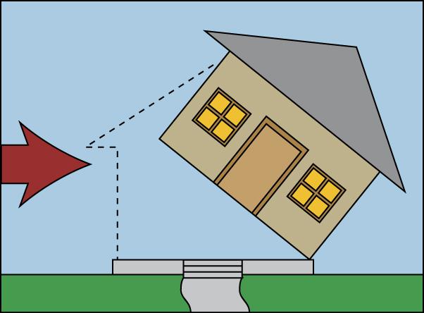
9 Wind Actions on Buildings Uplift Roof only Entire building Lateral loads (base shear) Connection between building and foundation Racking Pushing building over at the top Overturning Pushing building over when connection to foundation fails 17 Wind Uplift Source: APA 18 9


10 Source: APA 19 Base Shear (Sliding) Source: APA 20 10


11 Source: APA 21 Racking Source: APA 22 11

12 Source: APA 23 Overturning Source: APA 24 12

13 Source: APA 25 Load Path Through Building Wind pressure is collected by walls and roof Pressure is distributed into diaphragms at roof and floor levels Diaphragms take loads into shear walls Shear walls must be stiff enough to not rack and take loads into foundation Shear walls must be tied down to resist overturning 26 13
14 Developing Wind Design Pressures Developing pressures for wind design requires combining: Meteorological aspects of wind Speed Turbulence Interaction of wind with terrain Aerodynamics Interaction of wind with building 27 Basic Wind Equation p = q * G * C p p = Wind Pressure q = Velocity Pressure (Atmospheric Effects). G = Gust Effect Factor (Atmospheric & Aerodynamic Effects). C p = Pressure Coefficient / Shape Factor (Aerodynamic Effects)
15 Velocity Pressure q = ( V 2 ) K z K zt K d ASCE 7 adds two more factors: Topographic Factor K zt Hills and Escarpments Directionality Factor K d 0.85 for all building structures 29 ASCE 7 Basic Wind Equation For buildings with External and Internal Pressure: p = qgc p q i (GC pi ) Eq q i = Velocity pressure calculated for internal pressure, usually at mean roof height h GC pi = Internal Pressure Coefficient (+/ 0.18 for enclosed conditions) ASCE 7 calls this Directional Procedure (All Heights) 30 15
16 MWFRS Procedure used in WFCM p = q h [(GC pf ) (GC pi )] Eq where: q h = velocity pressure at mean roof height h GC pf = external pressure coefficient GC pi = internal pressure coefficient 31 MWFRS Load Case A ASCE 7 Used with MWFRS procedure in ASCE 7 and for WFCM 32 16
17 Process for Applying Loads Site determine wind speed and exposure Design based on most extreme exposure expected Find q (velocity pressure) for variety of windward heights and for h Determine p (wind pressure) for all surfaces for both + and internal pressure Wind pressures act normal to surfaces Design with the most restrictive pressures 33 Mean Roof Height 34 17

18 Exposure Categories B Suburban, use as DEFAULT unless others apply >60% to 80% of all buildings are in this category C Open country, 1500 ft creates this category D Water, including on hurricane coast! Change in ASCE 7-10 It s about Flow Characteristics vs. Surface Roughness 35 Exposure B Suburban 36 18

19 Exposure C 37 ACSE 7-10 Figure External Pressure Coefficients 38 19


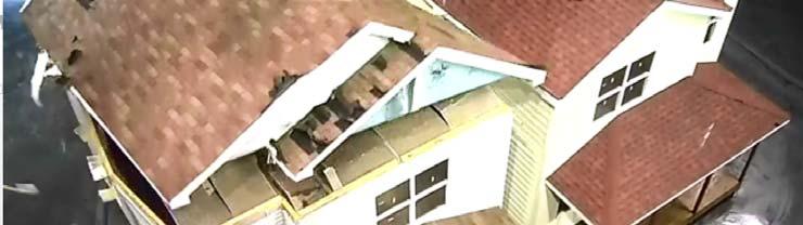

20 Wind Effects on Buildings IBHS wind tunnel tests center/ 39 IBHS Wind Tunnel Test Results 40 20
21 Example For h = 33 ft tall building, 40 ft (windward face) x 20 ft in plan, find: Roof to wall connection load Load taken into shear walls on ends of house Wind speed = 140 mph Exposure B condition 5:12 roof slope (20 0 is taken as worst case) GC pi = +/ 0.18 (enclosed condition) 41 Calculated Roof Pressures h Kz V q ASDq GCpwind +Gcpi Gcpi GCp lee +GCpi GCpi
22 Converting Pressure to Loads Wind pressures determined for roofs and walls must be converted to loads Pressure x tributary area = loads Loads may be reduced at points in the structure because weight is providing resistance Correct distribution of the loads is key to accurate design 43 Sum Moments to Determine Uplift Load 33 ft 20 ft Tension Tension (connector load) = 122 lbs 44 22
23 WFCM Roof to Wall Connection 45 Roof Wall Connector Load Using roof pressures from calculation procedure (see Slide 41) For 20 ft. roof span, connector load is determined by summing moments about one wall/roof joint. Result = 214 lb Reduce for dead load of roof system: WFCM uses 9 psf as reduction for dead load (90 lb at each wall) WFCM result = 165 x 0.75 reduction = 124 lb (reduction allowed when 8 ft away from roof edge) 46 23
 Total shear wall load distributed along the wall to foundation connection WFCM result = 218 plf x L/W (40/20) = 436 plf 48")
24 MKB10 General Lateral Load Path 47 Calculated Lateral Pressures Horizontal roof load distributed to shear walls Wall pressures distributed to shear walls (windward + leeward) Total shear wall load distributed along the wall to foundation connection WFCM result = 218 plf x L/W (40/20) = 436 plf 48 24
25 Slide 47 MKB10 It seems like this slide could be used in conjunction with slide 21. Michelle Kam-Biron, 8/1/2013
 (GC pi )] Eq. 30.4-1 Buildings with h 60 ft.")
26 WFCM Sill Plate to Foundation Connection 49 C&C Pressure Equations Low rise buildings with h 60 ft. based on Envelope Procedure p = q h [(GC p ) (GC pi )] Eq Buildings with h 60 ft. based on Directional Procedure p = q(gc p ) q i (GC pi ) Eq


27 Components & Cladding Walls Roofs 51 Questions?


28 THANK YOU! Follow up with: SurveyMonkey, presentation links and info. on Certificates Instructor: William L. Coulbourne, PE Sept. 4 th 2012 WFCM: Wind Speed and Design Pressure Determination According to ASCE 7 10 Sept. 11 th 2012 WFCM: Wind Load Distribution on Buildings Load Paths Sept. 18 th 2012 WFCM: Connections Sept. 25 th 2012 WFCM: Foundation Design to Resist Flood Loads and WFCM Calculated Wind Loads NEW! Nov. 21 st Prescriptive Residential Wood Deck Construction Guide (DCA 6) NEW! Jan. 16 th AWC s Code Conforming Wood Design
2012 Wood Frame Construction Manual: Wind Load Distribution on Buildings Load Paths
 2012 Wood Frame Construction Manual: Wind Load Distribution on Buildings Load Paths Presented by: William L. Coulbourne, PE Copyright Materials This presentation is protected by US and International Copyright
ASCE 7-10 Significant Changes to the Wind Load Provisions
 ASCE 7-10 Significant Changes to the Wind Load Provisions William L. Coulbourne, P.E. SECB Applied Technology Council (ATC) bcoulbourne@atcouncil.org Acknowledgements Ron Cook, Univ. of Florida, Wind Load
CALCULATING WIND LOADS ON LOW-RISE STRUCTURES PER 2015 WFCM ENGINEERING PROVISIONS (STD342-1)
") CALCULATING WIND LOADS ON LOW-RISE STRUCTURES PER 015 WFCM ENGINEERING PROVISIONS (STD34-1) John Buddy Showalter, P.E. Vice President, Technology Transfer American Wood Council Description The Wood Frame
CALCULATING WIND LOADS ON LOW-RISE STRUCTURES PER 015 WFCM ENGINEERING PROVISIONS (STD34-1) John Buddy Showalter, P.E. Vice President, Technology Transfer American Wood Council Description The Wood Frame
Appendix I ESTIMATED DESIGN WIND PRESSURE AND STRENGTHS OF CONNECTIONS OF JOPLIN HOME DEPOT BUILDING
 ESTIMATED DESIGN WIND PRESSURE AND STRENGTHS OF CONNECTIONS OF JOPLIN HOME DEPOT BUILDING I.1 ESTIMATED DESIGN WIND PRESSURE BASED ON BOCA NBC/1996 Basic design wind speed: V = 90 mph (3 s gust) Exposure
What is Conventional Construction?
 What is Conventional Construction? Copyright This presentation is protected by US and International Copyright laws. Reproduction, distribution, display and use of the presentation without written permission
Considerations for Outof-Plane. Design
 Considerations for Outof-Plane Wall and Uplift Design WoodWorks Texas Workshops December, 2016 Overview Uplift Wall Design Wind Loads Wind loads acting on buildings are modeled as uniform surface loads.
LATERAL LOADS ON BRICK VENEER RESIDENTIAL STRUCTURES
 LATERAL LOADS ON BRICK VENEER RESIDENTIAL STRUCTURES W. Mark McGinley 1, PhD, PE and Eric N. Johnson 2, PE ABSTRACT In North American residential construction, brick veneer is typically used as a cladding
130 MPH EXPOSURE B WFCM GUIDE. Guide to Wood Frame Construction in High Wind Areas for One- and Two-Family Dwellings 2015 EDITION
 130 MPH EXPOSURE B WFCM GUIDE Guide to Wood Frame Construction in High Wind Areas for One- and Two-Family Dwellings 2015 EDITION Updates and Errata While every precaution has been taken to ensure the accuracy
Lateral load basics Code acceptance of Standard. Standard Overview 2008 Wind & Seismic Standard. Wind. Wind Load Path. IBC Section 1604.
 Outline 2005/2008 Special Design Provisions for Wind & Seismic Standard Lateral load basics Code acceptance of Standard 2005/2008 Wind & Seismic Standard Overview 2008 Wind & Seismic Standard John Buddy
Special Inspections for Wood Construction BCD710 Michelle Kam-Biron, PE, SE, SECB Senior Director, Education American Wood Council
 Special Inspections for Wood Construction BCD710 Michelle Kam-Biron, PE, SE, SECB Senior Director, Education American Wood Council Copyright Materials This presentation is protected by US and International
MAT109: Introduction to the Wood Frame Construction Manual
 MAT109: Introduction to the Wood Frame Construction Manual One of the documents published by AF&PA is the Wood Frame Construction Manual for One- & Two-Family Dwellings. The WFCM is referenced in the IRC
WFCM 130 MPH GUIDE EXPOSURE B WOOD FRAME CONSTRUCTION MANUAL GUIDE TO WOOD CONSTRUCTION IN HIGH WIND AREAS FOR ONE- AND TWO-FAMILY DWELLINGS
 130 MPH EXPOSURE B GUIDE WFCM WOOD FRAME CONSTRUCTION MANUAL GUIDE TO WOOD CONSTRUCTION IN HIGH WIND AREAS FOR ONE- AND TWO-FAMILY DWELLINGS A F & P A American Forest & Paper Association American Wood
Shear Wall Design Examples per 2015 WFCM and 2015 SDPWS
 Shear Wall Design Examples per 2015 WFCM and 2015 SDPWS Copyright Materials This presentation is protected by US and International Copyright laws. Reproduction, distribution, display and use of the presentation
Learning Objectives. Copyright Materials. This presentation is protected by US and International Copyright laws. Reproduction,
 The Wood Products Council is a Registered Provider with The American Institute of Architects Continuing Education Systems (AIA/CES). Credit(s) earned on completion of this program will be reported to AIA/CES
Lateral Design of Mid- Rise Wood Structures
 Lateral Design of Mid- Rise Wood Structures Presented by Ricky McLain, MS, PE, SE Technical Director WoodWorks Texas Workshops December, 2016 Insert picture of me graduating college Follow the load Following
Significant 2012 IBC, NDS and 2008 SDPWS Changes
 www.awc.org Engineered and Traditional Wood Framing Members Significant 2012 IBC, NDS and 2008 SDPWS Changes www.awc.org Presented by: Michelle Kam-Biron, PE, SE, SECB American Wood Council - Director
APPENDIX. WOOD JOIST/RAFTER MAXIMUM SPANS ( for 16 o.c. spacing) WITH SINGLE ROW OF PV PANELS AT MIDSPAN (ft.) AND PANEL SUPPORT AT 32 o.c.
 WITH SINGLE ROW OF PV PANELS AT MIDSPAN (ft.) AND PANEL SUPPORT AT 32 o.c.") 1 Span Tables The following Wood Joist/Rafter Maximum Span Tables can be used to determine the adequacy of an existing wood framed roof structure to support the additional dead load created by PV panel
1 Span Tables The following Wood Joist/Rafter Maximum Span Tables can be used to determine the adequacy of an existing wood framed roof structure to support the additional dead load created by PV panel
Significant 2012 IBC, NDS and 2008 SDPWS Changes
 Significant 2012 IBC, NDS and 2008 SDPWS Changes Speaker s Name Title American Wood Council Engineered and Traditional Wood Framing Members Copyright Materials This presentation is protected by US and
Florida Structural Engineers
 Florida Structural Engineers South Florida Chapter January 8, 2008 Miami Lakes, Florida Aluminum Association of Florida, Inc. Joe Belcher ~ David Miller AAF Code Involvement: Historical Perspective 1998:
Heel Blocking Requirements and Capacity Analysis. Overview Revised 3/22/2017
 Heel Blocking Requirements and Capacity Analysis Overview Revised 3/22/2017 SBCA has been the voice of the structural building components industry since 1983, providing educational programs and technical
Wood Frame Construction Manual for One- and Two-Family Dwellings 2015 EDITION WORKBOOK
 WFCM Wood Frame Construction Manual for One- and Two-Family Dwellings 2015 EDITION WORKBOOK Design of Wood Frame Buildings for High Wind, Snow, and Seismic Loads 2015 Wood Frame Construction Manual Workbook
R Code and Commentary for 2012 NC Residential Code final 03/06/13
 R602.10 Code and Commentary for 2012 NC Residential Code final 03/06/13 Commentary italicized and printed in red 1. Section R602.10 -- provides charging language for two simplified bracing approaches (isolated
Structural Technical Report #1 By Robert Whitaker
 Structural Technical Report #1 By Robert Whitaker Robert Whitaker Structural ~ Parfitt Parkview at Bloomfield Station Bloomfield, NJ 10-05-05 Executive summary This report covers the structural concepts
PROPOSED CHANGE TO THE 2012 BUILDING CODE O. REG. 332/12 AS AMENDED
 Ministry of Municipal Affairs PROPOSED CHANGE TO THE 2012 BUILDING CODE O. REG. 332/12 AS AMENDED CHANGE NUMBER: SOURCE: B-04-01-11 Ontario-NBC CODE REFERENCE: Division B / 4.1.7. DESCRIPTION OF THE PROPOSED
APPENDIX A - Seismic Terms, Tables and Figures:
 APPENDIX A - Seismic Terms, Tables and Figures: Seismic Design Force, (F p ) G-force that the unit must be able to withstand. This number is calculated using the factors described below. a S 0.4 P DS z
DESIGN & ENGINEERING GUIDE
 DESIGN & ENGINEERING GUIDE SOLARMOUNT: FLUSH-TO-ROOF DESIGN PUB2017MAR16 TABLE OF CONTENTS Table of Contents Getting Started Introduction 1 Installer Responsibility 2 Design Methodology 3 Project Requirements
MBOIA IRC Wall Bracing. Mark Halverson. Maine Building Officials and Inspectors Association. First Last
 Wall Bracing This document was prepared for the MBOIA and based on the wind speeds and Seismic Design Categories for Maine and shall only be used as a reference since the Wind Speeds and the Seismic Design
Technical Assignment 1 10/8/03
 Executive Summary Technical Assignment 1 10/8/03 The is 55 story high-rise condominium being built off the northern Miami coast. The structural design presented in this building is a direct result of its
Individual Truss Marking Is it a Building Code Requirement?
 Introduction: Individual Truss Marking Is it a Building Code Requirement? Released April 1, 2010 On January 1, 2008, the 2007 edition of the California Building Code (CBC) 1 was adopted for use and replaced
Comparative study of wind tunnel test results to international and Egyptian design codes
 Comparative study of wind tunnel test results to international and Egyptian design codes *Chang- Abdulmonem A. Badri 1), *Manar M. Hussein 2) and Walid A. Attia 3) 1), 2), 3) 1 Department of Structural
National Design Specification for Wood Construction. Copyright Materials. Learning Objectives
 National Design Specification for Wood Construction The Wood Products Council is a Registered Provider with The American Institute of Architects Continuing Education Systems (AIA/CES). Credit(s) earned
Meeting Residential Energy. Construction. Copyright Materials. Loren Ross, P.E. Manager, Engineering Research American Wood Council
 Meeting Residential Energy Requirements with Wood-Frame Construction Loren Ross, P.E. Manager, Engineering Research American Wood Council Copyright Materials This presentation is protected by US and International
INTERIOR SHEAR WALLS. DESIGN AID No.. 8. American Forest & Paper Association. American Wood Council L MAX = 36' 16' 20' Wall C
 INTERIOR SHEAR WALLS L MAX = 36' 16' 20' DESIGN AID No.. 8 8' tributary 10' tributary American Forest & Paper Association 2 DESIGN AID No. 8 INTERIOR SHEAR WALLS The (AWC) is part of the wood products
Residential Wood Deck Design
 Residential Wood Deck Design EARN 0.1 ICC Continuing Education Unit (CEU) and/or AIA/CES HSW 1 Learning Unit (LU) BCD303-A Residential Wood Deck Design Description: Deck and balcony collapses injure occupants
System Report. Design for Combined Shear and Uplift from Wind. and equipment, and Section Analysis
 ystem Report R-101B JANUARY 2010 Design for Combined hear and Uplift from Wind 1. BAI OF THE YTEM REPORT n 2009 and 2006 International Building Code: ections 104.11 Alternative materials, design and methods
ANALYSIS AND DESIGN OF MOMENT RESISTING MIDWALL BY THE STEEL NETWORK, INC.
 ANALYSIS AND DESIGN OF MOMENT RESISTING MIDWALL BY THE STEEL NETWORK, INC. Paul Lackey, P.E., Muhammad Ghoraba, Nabil A. Rahman, Ph.D., P.E. and Kurtis Kennedy MidWall is a hold-down product intended to
Association of Caribbean States 2003
 MODEL BUILDING CODE FOR WIND LOADS Final Version, May 2003 Association of Caribbean States 2003 5-7 Sweet Briar Road, St. Clair, P.O. Box 660 Port of Spain, Trinidad and Tobago, West Indies Tel: (868)
Suspended Metal lath and Cement Plaster. Coverings Rigid Insulation, 1/2 - in 0.75 psf. Floor Fill Lightweight Concrete, per inch 8 psf
 Dead Loads Ceiling Suspended Metal lath and Cement Plaster 15 psf Coverings Rigid Insulation, 1/2 - in 0.75 psf Floor Fill Lightweight Concrete, per inch 8 psf Floor Finish Frame Partitions Ceramic or
SAMPLE PROJECT IN WASHINGTON DC DOCUMENT NO. CALC LOADS AND LOAD COMBINATIONS 9 PROJECT ENGINEER. Pages REVISION TITLE
 PROJECT DOCUMENT NO. CALC-110 0 TITLE LOADS AND LOAD COMBINATIONS 9 ENGINEER REVISION Pages LOADS AND LOAD COMBINATIONS 2 of 9 Table of contents 1 Basic Data... 3 1.1 References... 3 2 Loads... 4 2.1 Live
Floor Truss Ribbon Board Load Path
 Floor Truss Ribbon Board Load Path SRR No. 1506-16 Structural Building Components Association (SBCA) July 26, 2016 SBCA is an APPROVED SOURCE This research report is based on practical scientific research
On Cold-Formed Steel Construction. Light Gauge Steel Engineers Association Washington, D.C Toll Free (866)
") TECHNICAL NOTE On Cold-Formed Steel Construction $5.00 Light Gauge Steel Engineers Association Washington, D.C. 20005 Toll Free (866) 465-4732 www.lgsea.com DESIGN OF BY-PASS SLIP CONNECTORS IN COLD-FORMED
TECHNICAL NOTE On Cold-Formed Steel Construction $5.00 Light Gauge Steel Engineers Association Washington, D.C. 20005 Toll Free (866) 465-4732 www.lgsea.com DESIGN OF BY-PASS SLIP CONNECTORS IN COLD-FORMED
SDPWS. Special Design Provisions for Wind & Seismic 2015 EDITION
 SDPWS Special Design Provisions for Wind & Seismic 2015 EDITION ANSI/AWC SDPWS-2015 Approval date September 8, 2014 Updates and Errata While every precaution has been taken to ensure the accuracy of this
Figure 1 Shear wall segments with mono-sloped top plates
 All text, images and diagrams Copyright 2004 by Thor Matteson and ICC APPENDIX B ENGINEERING PRINCIPLES OF SHEAR WALLS WITH SLOPING TOP PLATES APA The Engineered Wood Association and others have tested
PRESENTATION OUTLINE MUBEC & IRC APPLICABILITY & ADMIN. 6/17/2015 RESIDENTIAL STRUCTURAL SYSTEMS. Carmen B. Bombeke, P.E.
 MUBEC & IRC APPLICABILITY & ADMINISTRATION RESIDENTIAL STRUCTURAL SYSTEMS Carmen B. Bombeke, P.E. IRC FLOORS QUESTIONS & ANSWERS PRESENTATION OUTLINE Maine Uniform Building & Energy Code (MUBEC) IRC 2009
NATIONAL HARBOR BUILDING M OXON HILL, MARYLAND. Ryan Sarazen Structural Option Technical Report 3 Faculty Consultant: Dr.
 NATIONAL HARBOR BUILDING M OXON HILL, MARYLAND Ryan Sarazen Structural Option Technical Report 3 Faculty Consultant: Dr. Andres Lepage Table of Contents Executive Summary.. 3 Structural Systems Overview...
December 20, 2006 PARTIES INTERESTED IN EVALUATION REPORTS ON PATIO COVERS
 ICC EVALUATION SERVICE, INC. Evaluate P Inform P Protect December 20, 2006 TO: PARTIES INTERESTED IN EVALUATION REPORTS ON PATIO COVERS SUBJECT: Proposed Revisions to the Acceptance Criteria for Patio
WIND & SEISMIC 2008 EDITION ASD/LRFD WITH COMMENTARY. American Forest & Paper Association. American Wood Council ANSI/AF&PA SDPWS-2008
 2008 EDITION ANSI/AF&PA SDPWS-2008 Approval Date: August 4, 2008 ASD/LRFD WIND & SEISMIC Special Design Provisions for Wind and Seismic WITH COMMENTARY American Forest & Paper Association American Wood
CHAPTER 3 BUILDINGS WITH WOOD FRAMED EXTERIOR WALLS 301 SCOPE
 CHAPTER 3 BUILDINGS WITH WOOD FRAMED EXTERIOR WALLS WOOD CHAPTER 3 301 SCOPE This chapter prescribes construction requirements for buildings where all exterior walls above the foundation are wood framed
PEER/CSSC Tall Building Design Case Study Building #1. J. Andrew Fry John Hooper Ron Klemencic Magnusson Klemencic Associates
 PEER/CSSC Tall Building Design Case Study Building #1 J. Andrew Fry John Hooper Ron Klemencic Magnusson Klemencic Associates Building Information Located in Los Angeles 42-Story 410 ft Tall 108 ft X 107
Structural Redesign Gravity System
 Redesign Gravity System Design Considerations A composite floor system was used for this design to maximize the efficiency of the material being used. This type of system requires less material and provides
2009 IRC Wall Bracing
 2009 IRC Wall Topics www.iccsafe.org Item no. 7102S09 Mark Halverson Manager Field Services Division P The Engineered Wood ssn. Topics Introduction: Lateral Forces Introduction Lateral Forces Getting Started
Copyright. magazine. CFS Load Bearing Construction
 Progressive Collapse Requirements Cold-Formed Steel Load Bearing Construction By Nabil A. Rahman, Ph.D., P.E., Michael Booth and Gary Bennett Figure 1: Cold formed steel load bearing mid-rise construction.
Loads and Load Paths. "Architecture is inhabited sculpture." -Constantin Brancusi
 Loads and Load Paths "Architecture is inhabited sculpture." -Constantin Brancusi Loads and Load Paths Structural Design Design Loads Dead Load Live Load Snow Load Lateral Loads Load Types Load Combinations
Residential, 26 Ga. Roof Panel over 15/32 Plywood. Florida Product Approval # R3 Florida Building Code 2017 Per Rule 61G20-3 Method: 1 D
 Product Evaluation Report REED S METAL, INC. Residential, 26 Ga. Roof Panel over 15/32 Plywood Florida Product Approval # 12725.2 R3 Florida Building Code 2017 Per Rule 61G20-3 Method: 1 D Category: Roofing
2012 International Building Code Errata (Portions of text and tables not shown are unaffected by the errata)
") SEVENTH PRINTING (Updated October 13, 2014) Figure 1608.2 GROUND SNOW LOADS, p g, FOR THE UNITED STATES (psf) (Revise southern California values as indicated in the figure) SIXTH PRINTING (Updated June
SEVENTH PRINTING (Updated October 13, 2014) Figure 1608.2 GROUND SNOW LOADS, p g, FOR THE UNITED STATES (psf) (Revise southern California values as indicated in the figure) SIXTH PRINTING (Updated June
Wall Bracing. Part 1: Basic Components for Code Compliant Bracing
 The Pennsylvania Housing Research/Resource Center Wall Bracing. Part 1: Basic Components for Code Compliant Bracing Builder Brief: BB0807 Bo Kasal, Hankin Chair, Director of Research PHRC, and Jay Crandell,
Wind Tunnel Applications for Buildings
 Wind Tunnel Applications for Buildings Presented by: Jim Swanson, Halvorson and Partners Donald Scott, PCS Structural Solutions Jon Galsworthy, RWDI Add Company Logo Here Outline 1. Introduction 2. ASCE7
LPI 56 Technical Guide
 LPI 56 Technical Guide Floor & Roof Applications Product Specifications & Design Values 2 Floor Tables 3 Uniform Floor Load (PLF) Tables: Simple s 4 Uniform Floor Load (PLF) Tables: Continuous s 5 Uniform
W. Mark McGinley March 3, 2016 ISEA MEETINGS 1
 J.B. SPEED SCHOOL OF ENGINEERING Design of s for Masonry Veneers W. Mark McGinley, Ph. D., PE FASTM MASONRY DAY Indianapolis March 3, 2016 Objectives Present a Brief Overview of: Masonry Veneer Wall systems
Structural System. Design Criteria Fire Resistance Concrete designed for 2 HR rating (worst case) Geotechnical Report Allowable Bearing Capacity
 Geotechnical Report Allowable Bearing Capacity") System Codes and Criteria Design Codes and Standards The design code used is the Wisconsin Administrative Code along with the State of Wisconsin Department of Commerce-Safety & Buildings Chapters Comm
System Codes and Criteria Design Codes and Standards The design code used is the Wisconsin Administrative Code along with the State of Wisconsin Department of Commerce-Safety & Buildings Chapters Comm
TESTING APPLICATION STANDARD (TAS) No TEST PROCEDURE FOR WIND AND WIND DRIVEN RAIN RESISTANCE OF DISCONTINUOUS ROOF SYSTEMS
 No TEST PROCEDURE FOR WIND AND WIND DRIVEN RAIN RESISTANCE OF DISCONTINUOUS ROOF SYSTEMS") TESTING APPLICATION STANDARD (TAS) No. 100-95 TEST PROCEDURE FOR WIND AND WIND DRIVEN RAIN RESISTANCE OF DISCONTINUOUS ROOF SYSTEMS 1. 2. Scope 1.1 This Protocol covers the determination of the water infiltration
TESTING APPLICATION STANDARD (TAS) No. 100-95 TEST PROCEDURE FOR WIND AND WIND DRIVEN RAIN RESISTANCE OF DISCONTINUOUS ROOF SYSTEMS 1. 2. Scope 1.1 This Protocol covers the determination of the water infiltration
Wood Design for Architects: Engineering for the Non-engineer. AIA Statement
 Wood Design for Architects: Engineering for the Non-engineer AIA Statement The Wood Products Council is a Registered Provider with The American Institute of Architects Continuing Education Systems (AIA/CES).
GARAGES/ONE-STORY City of Grand Rapids Building Safety Division
 GARAGES/ONE-STORY City of Grand Rapids Building Safety Division 218-326-7601 www.cityofgrandrapidsmn.com This handout is intended only as a guide and is based in part on the 2015 Minnesota State Building
Spring Hill Suites Marriott
 Spring Hill Suites Marriott Project Location: Amarillo, TX Prepared for: Girder Slab Technologies Contact: Daniel Fisher, Sr. January 15, 2008 Prepared by: Monica Stockmann Regional Engineer: Erika Winters-Downey
INTERNATIONAL ASSOCIATION OF PLUMBING AND MECHANICAL OFFICIALS UNIFORM EVALUATION SERVICES EVALUATION CRITERIA FOR
 INTERNATIONAL ASSOCIATION OF PLUMBING AND MECHANICAL OFFICIALS UNIFORM EVALUATION SERVICES EVALUATION CRITERIA FOR THE TESTING AND ANALYSIS OF STEEL SHEET SHEATHING FOR WOOD AND COLD FORMED STEEL LIGHT
Nabil A. Rahman, Ph.D., P.E.
 STIFFWALL STRAP BRACING SHEAR WALL SYSTEM Nabil A. Rahman, Ph.D., P.E. Introduction Buildings require a vertical load resisting system to provide lateral stiffness and to transfer acting lateral loads
Understanding IBC Wind Load Requirements for Generating Systems
 Understanding IBC Wind Load Requirements for Generating Systems By: Allan Bliemeister Senior Staff Engineer Kohler Power Systems It is important for standby power system enclosures to withstand loads produced
Global Village Rochester Institute of Technology Rochester, New York
 Presentation Outline Welcome Introduction Architecture Existing Structure Problem Statement Arch. Breadth Structural Depth Conclusion Questions Global Village Rochester Institute of Technology Rochester,
Tables with Allowable ASD Seismic Values For Design at R = 6.5. Special Moment Frame MF1-12
 Tables with Allowable ASD Seismic Values For Design at R = 6.5 Special Moment Frame MF1-12 Hardy Frames, Inc manufactures and markets pre-fabricated shear wall systems. We have been the innovative leader
WIND LOADS ON BALUSTRADES. Antonios W. Rofail a, Christian Mans a
 WIND LOADS ON BALUSTRADES Antonios W. Rofail a, Christian Mans a a Windtech Consultants, 19 Willis Street, Wolli Creek, NSW, Australia ABSTRACT: This paper examines the wind loading on impermeable balustrade
CE 3150 Reinforced Concrete Design Design Project
 Problem Description For this design project you will work in your project groups to complete a partial design of an office building. Specifically, you will design and fully detail three components: 1.
Structural Technical Report 3 Lateral System Analysis and Confirmation Design
 Structural Technical Report 3 Lateral System Analysis and Confirmation Design James Wilson Structural Option AE 481W Senior Thesis The Pennsylvania State University Faculty Consultant: Professor M. Kevin
ROOFING APPLICATION STANDARD (TAS) No. 102(A)-95
 No. 102(A)-95") ROOFING APPLICATION STANDARD (TAS) No. 102(A)-95 TEST PROCEDURE FOR STATIC UPLIFT RESISTANCE OF MECHANICALLY ATTACHED, CLIPPED, RIGID, ROOF SYSTEMS (For Methods of Mechanical Attachment Excluding Clips,
ROOFING APPLICATION STANDARD (TAS) No. 102(A)-95 TEST PROCEDURE FOR STATIC UPLIFT RESISTANCE OF MECHANICALLY ATTACHED, CLIPPED, RIGID, ROOF SYSTEMS (For Methods of Mechanical Attachment Excluding Clips,
CVEN 483. Structural System Overview
 CVEN 483 Structural System Overview Dr. J. Bracci Fall 2001 Semester Presentation Overview 1. Building system primary function 2. Types of load 3. Building materials 4. Structural members 5. Structural
ALLOWABLE STRESS DESIGN OF CONCRETE MASONRY LINTELS. TEK 17-1C Structural (2009) Related TEK: Uniform load. Triangular load. Concentrated loads
 Related TEK: Uniform load. Triangular load. Concentrated loads") An information series from the national authority on concrete masonry technology ALLOWABLE STRESS DESIGN OF CONCRETE MASONRY LINTELS TEK 17-1C Structural (2009) INTRODUCTION Lintels and beams are horizontal
An information series from the national authority on concrete masonry technology ALLOWABLE STRESS DESIGN OF CONCRETE MASONRY LINTELS TEK 17-1C Structural (2009) INTRODUCTION Lintels and beams are horizontal
Chapter 2 EARTHQUAKE-RESISTANCE REQUIREMENTS
 Chapter 2 EARTHQUAKE-RESISTANCE REQUIREMENTS This chapter explains the International Residential Code s (IRC s) general earthquake-resistance requirements as well as specific IRC requirements concerning
SECTION PLATE CONNECTED WOOD TRUSSES
 SECTION 06173 PLATE CONNECTED WOOD TRUSSES PART 1 GENERAL 1.01 SUMMARY A. Section Includes: 1. Shop fabricated wood trusses for roof and floor framing. 2. Bridging, bracing, and anchorage. B. Related Sections:
Seismic Load Determination for Residential Decks
 Seismic Load Determination for Residential Decks Garrett H. Lyman, and Donald A. Bender, Ph.D., P.E., J. Daniel Dolan, Ph.D., P.E. Introduction Both the 009 International Residential Code (IRC) Section
2010 Edition of ASCE 7 Minimum Design Loads for Buildings and Other Structures Errata No.2 Effective: March 31, Chapter 4
 Edition of ASCE 7 Errata No.2 Effective: March 31, 13 This document contains errata to ASCE 7- and is periodically updated and posted on the SEI website at www.asce.org/sei/errata. THIS TYPE AND SIZE FONT
Florida Product Approval # R3 Florida Building Code 2017 Per Rule 61G20-3 Method: 1 D
 Product Evaluation Report REED S METALS, INC. Perma-Lok, 26 Ga. 16 Coverage Roof Panel over 15/32 Plywood Florida Product Approval # 12725.1 R3 Florida Building Code 2017 Per Rule 61G20-3 Method: 1 D Category:
Structural Technical Report 1 Structural Concepts / Structural Existing Conditions Report
 Michael A. Troxell Structural Option Advisor: Professor Parfitt College of Business Administration Oct. 5, 2005 Structural Technical Report 1 Structural Concepts / Structural Existing Conditions Report
R CODE CHANGE PROPOSAL FORM (See instructions on page 2)
") CODE CHANGE PROPOSAL FORM (See instructions on page 2) Code: IRC 12/13 Sections 301.2.2.2.1 Proponent: Charles S. Bajnai, Chesterfield County, VA, ICC Building Code Action Committee 1. Delete as shown
CODE CHANGE PROPOSAL FORM (See instructions on page 2) Code: IRC 12/13 Sections 301.2.2.2.1 Proponent: Charles S. Bajnai, Chesterfield County, VA, ICC Building Code Action Committee 1. Delete as shown
Sponsored by The Boston Association of Structural Engineers and the Structural Engineers Association of Massachusetts
 Commonwealth of Massachusetts State Building Code 780-CMR 9 th Edition Renovation of Existing Buildings Using The International Existing Building Code IEBC 2015 with Massachusetts Amendments Sponsored
Precast Concrete Bearing Wall Panel Design (Alternative Analysis Method) (Using ACI )
 (Using ACI )") Precast Concrete Bearing Wall Panel Design (Alternative Analysis ethod) (Using ACI 318-14) Precast Concrete Bearing Wall Panel Design (Alternative Analysis ethod) (Using ACI 318-14) A structural precast
Precast Concrete Bearing Wall Panel Design (Alternative Analysis ethod) (Using ACI 318-14) Precast Concrete Bearing Wall Panel Design (Alternative Analysis ethod) (Using ACI 318-14) A structural precast
Part III Building Planning and Construction
 Part III Building Planning and Construction CHAPTER 3 BUILDING PLANNING SECTION R301 DESIGN CRITERIA R301.1 Application. Buildings and structures, and all parts thereof, shall be constructed to safely
Steel Roof Trusses. An Overview on Designing, Manufacturing, and Installing Roof Trusses. Truss Types. Southline steel Industries i
 Southline steel Industries i Steel Roof Trusses An Overview on Designing, Manufacturing, and Installing Roof Trusses Most building roofs can be framed with engineered lightgauge steel trusses which are
REPORT HOLDER: AEROSMITH FASTENING SYSTEMS 5621 DIVIDEND ROAD INDIANAPOLIS, INDIANA EVALUATION SUBJECT: AEROSMITH BRAND FASTENERS
 0 Most Widely Accepted and Trusted ICC-ES Report ICC-ES 000 (800) 423-6587 (562) 699-0543 www.icc-es.org ESR-3145 Reissued 02/2017 This report is subject to renewal 02/2018. DIVISION: 05 00 00 METALS SECTION:
3.5 Tier 1 Analysis Overview Seismic Shear Forces
 Chapter 3.0 - Screening Phase (Tier ) 3.5 Tier Analysis 3.5. Overview Analyses performed as part of Tier of the Evaluation Process are limited to Quick Checks. Quick Checks shall be used to calculate the
Wind Pressure Testing of Tornado Safe Room Components Made from Wood
 United States Department of Agriculture Wind Pressure Testing of Tornado Safe Room Components Made from Wood Robert H. Falk Deepak Shrestha Forest Service Forest Products Laboratory Research Paper FPL
Snow load design using the 2003 International Building Code
 Snow load design using the 2003 International Building Code By John R. Henry, P.E. Early model building codes transcribed design provisions from various sources and standards. More recent editions of the
Evaluation of Full-Scale House Testing Under Lateral Loading
 Evaluation of Full-Scale House Testing Under Lateral Loading Prepared for National Association of Home Builders Prepared by NAHB Research Center 400 Prince Georges Boulevard Upper Marlboro, MD 20774-8731
Allowable Loads for Round Timber Poles
 UNIVERSITY OF ALASKA FAIRBANKS Allowable Loads for Round Timber Poles HCM-00752 UNIVERSITY OF ALASKA FAIRBANKS The following publication is a major upgrade of information for calculating and understanding
PHOTO 1: View from Inside the Structure. Note the Rotation of the WSP, Failure at the Lower Leading Edge and Deformation of the Top Plate
 2009 International Residential Code (IRC) Braced Wall Panel Design Value Comparative Equivalency Testing Braced Wall Panel Design Values July 15, 2010 Introduction: SBCRI undertook 39 tests resulting in
MAX-CORE I-JOIST DESIGN MANUAL-US
 MAX-CORE I-JOIST DESIGN MANUAL-US FRAMED BY QUALITY BUILT WITH SUCCESS OUR COMPANY At International Beams Inc. we take pride in providing our customers with premium quality products and services. Our full
Modular Wood Framing Goes Vertical
 Modular Wood Framing Goes Vertical By: Troy Bean, P.E., S.E. DCI Engineers January 2013 The Wood Products Council is a Registered Provider with. Credit(s) earned on completion of this program will be reported
Review of ASCE 7-05 unbalanced snow load provisions and their effect on building design By Leo Shirek P.E. Wick Buildings
 researchandtechnology Review of ASCE 7-05 unbalanced snow load provisions and their effect on building design By Leo Shirek P.E. Wick Buildings Fig 1. Balanced and unbalanced snow loads Introduction Early
HAZUS Coastal Storm Surge Model
 HAZUS User Conference Indianapolis August 24, 2010 HAZUS Coastal Storm Surge Model Frank Lavelle, Peter Vickery, Bo Yu, and Sudhan Banik Applied Research Associates, Inc. Raleigh, NC (919) 582-3350 Project
The Structural Redesign of Boyds Bear Country and its Related Systems. Boyds Bear Country, Pigeon Forge, Tennessee
 The Structural Redesign of Boyds Bear Country and its Related Systems Included in this Presentation: Background and Existing System Proposal Problem / Solution Structural System Redesigns Pre-cast Concrete
DIVISION: THERMAL AND MOISTURE PROTECTION SECTION: METAL ROOF PANELS SECTION: METAL WALL PANELS REPORT HOLDER:
 0 Most Widely Accepted and Trusted ICC ES Evaluation Report ICC ES 000 (800) 4 6587 (562) 699 0543 www.icc es.org ESR 3152 Reissued 08/2017 This report is subject to renewal 08/2018. DIVISION: 07 00 00
Joint Evaluation Report ICC-ES (800) (562)
 (562)") 0 Joint Evaluation Report ICC-ES (800) -658 (56) 699-05 www.icc-es.org 000 ESR-0 Reissued 0/0 This report is subject to renewal 0/08. DIVISION: 06 00 00 WOOD, PLASTICS AND COMPOSITES SECTION: 06 6 00 SHEATHING
0 Joint Evaluation Report ICC-ES (800) -658 (56) 699-05 www.icc-es.org 000 ESR-0 Reissued 0/0 This report is subject to renewal 0/08. DIVISION: 06 00 00 WOOD, PLASTICS AND COMPOSITES SECTION: 06 6 00 SHEATHING