Luka Quality Assurance Manual (Eng)
|
|
|
- Caitlin Edwards
- 6 years ago
- Views:
Transcription
1 Luka Quality Assurance Manual (Eng) Contents: 1 General Foreword Quality assurance standards for air ducts... 4 A.1.00 Rectangular galvanised steel ducts... 4 A.2.00 Embedded galvanised steel air ducts for residential buildings and floors equivalent to residential buildings A.3.00 Round galvanised steel ducts B.1.00 Rectangular aluminium ducts B.2.00 Round aluminium ducts C.1.00 Rectangular stainless steel ducts C.2.00 Round stainless steel ducts D.1.00 Rectangular plastic ducts D.2.00 Round plastic ducts E.1.00 Rectangular mineral wool ducts F.1.00 Rectangular rigid foam ducts G.1.00 Round flexible ducts, or hoses G.2.00 Flexible aluminium hoses G.3.00 Flexible aluminium foil hoses G.4.00 Flexible plastic hoses
2 H.1.00 Internal and external coating of air ducts I.1.00 Thermal insulation of rectangular and round air ducts J.1.00 Fire-resistant insulation and sheathing of metal air ducts K.1.00 Internal cleaning of air ducts L.1.00 Installation instructions M.1.00 Airtightness Quality control Quality guarantee External quality control by TÜV Rheinland Nederland BV Policy statement of members and associate members of LUKA Contract specifications
3 1 General 1.01 Foreword The purpose of the Luka Quality Assurance Manual is to serve as the basis for the quality attributes of the products and services guaranteed by Luka members and associate members. It also gives a clear insight into the quality philosophy of all the members, and the methodology of quality control by the independent institute TÜV Rheinland Nederland BV, a partner of Luka. With this publication, Luka s Environment and Technology Committee (Commissie Milieu & Techniek: CMT) hopes to have again achieved extra added value for the HVAC sector. Luka and those who assisted in compiling this manual have taken the greatest possible care with collecting, processing and formulating the information contained in this manual. Nevertheless, the possibility cannot be excluded here that this manual is incomplete or contains inaccuracies or errors. Therefore anyone who uses this manual and the information stated therein personally accepts the risk of this. Luka and those who assisted in compiling this manual exclude all liability for both damage that may result from the use of this information and damage that could arise as a result of the omissions, inaccuracies or errors of this manual. No part of this manual may be reproduced and/or transmitted in any form or by any means, printing, copying or otherwise, without the prior written permission of the board of Luka. The publication of this updated manual entails that the May 2004 version is no longer applicable.

4 2. Quality assurance standards for air ducts A.1.00 Rectangular galvanised steel ducts A.1.01 sheet quality For manufacturing galvanised air ducts, sheet steel of DX51 DZ 275 MAC quality, coated on both sides with a zinc layer according to the Sendzimir process, shall be used. The layer thickness shall be 275 g/m2 for both sides, measured according to the trihedral test. Sheet quality / zinc quality shall be in accordance with EN 10142, and tolerances shall be in accordance with EN (the zinc layer having an average thickness of 20 microns on each side). A.1.02 sheet thickness Galvanised air ducts shall made in a sheet thickness that is dependent upon the largest duct side, as specified below. The air ducts shall be manufactured at this thickness to ensure sufficient rigidity against distortion and to prevent disturbing vibrations. Based on the largest duct side, the following apply as minimum sheet thicknesses:
5 A.1.03 transverse joints For rectangular air ducts, various types of transverse joints can be used. These are company dependent, the quality of the sheet material from which the joint profiles shall be formed at least satisfying the requirements of the material from which the duct is manufactured. These transverse joints can (depending on the company) be attached to the duct by rolling, or fastened to the duct by means of projection welds, spot welds, screws or pop rivets. The transverse joints shall be coupled with clips, slide plates or clamps at a maximum centre-to-centre distance of 500 mm (see
6 drawing). To provide airtightness, a closed-cell sealing tape shall be applied between the transverse joints, the minimum dimensions being 18 x 4 mm (W x H) and all four corners being provided with galvanised bolts and nuts of at least size M6 x 20. If slide plates are used over the whole perimeter of the duct, the bolts and nuts at the corners may be omitted. Where necessary, to provide airtightness, permanently plastic sealant shall be applied internally or externally. A.1.04 longitudinal joints In principle, longitudinal joints between duct sections shall be made as a folded seam. Where necessary, to provide airtightness, permanently plastic sealant shall be applied internally or externally. A.1.05 reinforcements Air ducts shall be made with a rigidity sufficient to prevent disturbing vibrations and distortion. Assuming that the recommended minimum sheet thickness according to A.1.02 is used, this applies to rectangular metal ducts when the largest side of the cross-section is 400 mm. Additional provisions are required when this dimension is exceeded. The amount of the excess shall determine the necessary provisions. cross-breakings; crosswise embossments normally directed outwards; corrugations or folds: usually made at right-angles to the longitudinal axis of the duct at a mutual distance not exceeding 500mm. For ducts with a side dimension > 800 mm, the previously mentioned provisions for the duct walls apply, surfaces with an area greater than 1.5 m2 being additionally reinforced by partioning into subsections not greater than 1 m2. These additional reinforcements shall be fitted internally or externally in the form of strips, profiles, tubes or plates.

7 A.1.06 dimensions The nominal dimensions of the air ducts shall be given in mm and refer to the inside dimensions with a tolerance of +0 to -4 mm. The dimensions shall be standardised according to EN 1505 and can be selected as indicated in the table of standard dimensions. A.1.07 exposed ductwork If a section of the air duct system in an air-conditioning installation is intended as exposed ductwork, it shall be constructed as the rest of the ductwork, unless otherwise specified. When ductwork is intended as exposed ductwork, external stickers and labelling shall be removed, while the required

8 airtightness shall be obtained by internal application of sealant. Additional measures in the context of exposed ductwork are not normally included in the standard construction. A.1.08 bends A symmetrical bends In principle, symmetrical bends have a round shape, i.e. with an inside and an outside radius; the inside radius shall be at least 100 mm. (For floor or wall openings where there is no room for an inside radius, a right-angled inside bend shall be used.) To limit the friction in a bend, the bends shall be provided with vanes. Vanes are not required in the following cases: a bend of 45 or less; a duct with a width of 400 mm or less. The vanes shall be positioned according to the following table.
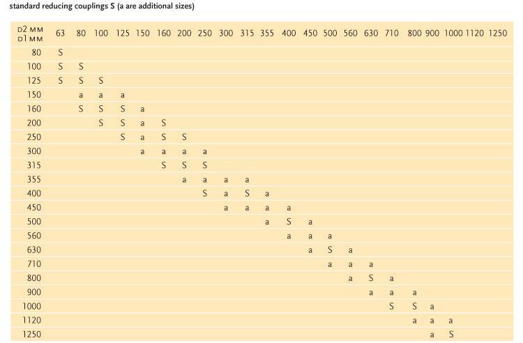
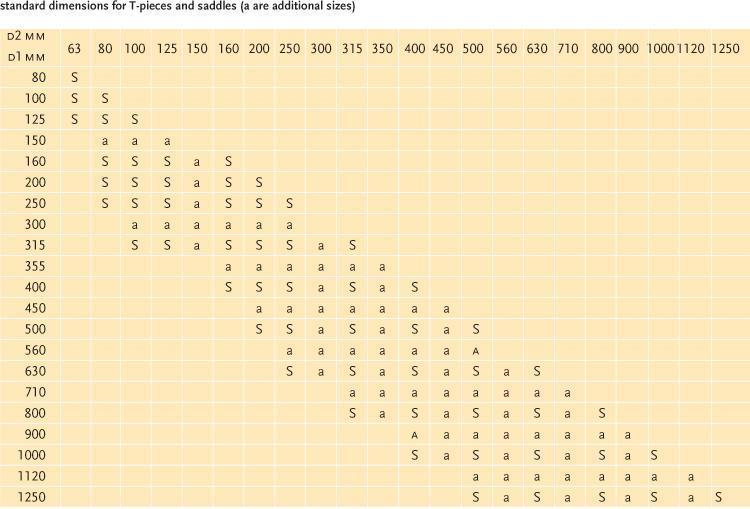
9 A reducing bends In the case of reducing bends, the smallest duct width shall determine the number of vanes according to the above table. The ratio for the position of the vanes at the largest duct width is then equal to the ratio for the vanes at the smallest duct width. A construction of vanes Vanes shall be made of single-thickness sheet. The sheet material shall be the same as that used for the duct. The construction and fastening shall be of sufficient strength, and the ends of the vanes shall be reinforced. A.1.09 reducing couplings Reducing couplings shall be made in such a way that the upper angle α may in principle be 60 maximum. A.1.10 branches A branch (a take-off in an ongoing section of main duct) can be made by means of a fitting, either rectangular or round. Technical aspects of air flow design co-determine the type, as shown in the drawings below.
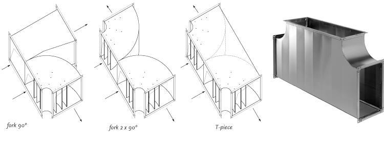
10 A.1.11 forks A fork is a subdivision of a main duct into two ongoing ducts. Examples of forks are:
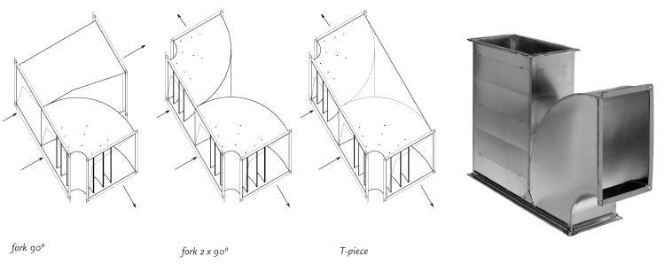
11
12 A.1.12 adjustable dampers Adjustable dampers serve for the regulation of an installation and shall be made manually adjustable. They shall be provided with a reliable securing device, which also shows the damper setting. The damper blade, made of the same material as the air duct, shall be made of singlethickness sheet with a thickness of at least 1.25 mm, a maximum blade width (B) of 500 mm and a maximum surface area of 0.25 m2. The edges of the damper blades shall be rounded and reinforced parallel to the axis. A.1.13 tolerances The maximum tolerance for the length of a straight duct is ±0.005 x L. The tolerance for the rectangular dimensions is +0 to -4 mm. The maximum tolerance for angles is ± 2.
13 A.2.00 Embedded galvanised steel air ducts for residential buildings and floors equivalent to residential buildings (intended for embedding in the concrete floor) A.2.01 sheet quality For manufacturing galvanised air ducts, sheet steel of minimum DX51 D 150 MAC quality, coated on both sides with a zinc layer according to the Sendzimir process, shall be used. The layer thickness shall be 150 g/m2 for both sides, measured according to the trihedral test. Sheet quality / zinc quality shall be in accordance with EN 10142, and tolerances shall be in accordance with EN (the zinc layer having an average thickness of approx. 10 microns on each side). A.2.02 sheet thickness Galvanised air ducts shall be made in a sheet thickness that is dependent upon the largest duct side. The embedded air ducts with the dimensions 170 x 70 and 170 x 80 shall be made in a sheet thickness of 0.5 mm, and with the dimensions 200 x 80 and 220 x 80 in a sheet thickness of 0.6 mm. Other sizes can be made on a customer-specific basis. A.2.03 transverse joints For rectangular embedded ducts, the transverse joints shall be made as a slide joint, using a coupling or sleeve.
14 This joint shall be fixed using self-tapping screws or where possible with spot welds and then finished with tape, in such a way that no water or cement can enter the air duct. A.2.04 longitudinal joints In principle, longitudinal joints shall be made as a seam weld, folded seam or spot weld. Where necessary, to provide airtightness, permanently plastic sealant shall be applied internally or externally. A.2.05 dimensions The ducts shall be made in the following dimensions: 170 x 70 mm, 170 x 80 mm, 200 x 80 mm, 220 x 80 mm. A.2.06 various types of rectangular embedded ducts A straight duct The straight ducts shall be supplied in standard lengths of 3 m.

15 A bends Bends shall be supplied in standard implementations as 90 or 45 bend and shall be streamlined. A coupling or sleeve Couplings or sleeves shall be supplied in standard lengths of 80, 100, 125, 200, 300 or 600 mm, depending on the supplier. Sleeves that are longer than 80 mm are also called connectors. A end cover End covers shall be supplied in all the standard sizes stated above. A T-pieces T-pieces shall be supplied with a minimum inside radius of 100 mm. A right-angled side fitting Using a right-angled side fitting, a T-piece with 90 internal angles can be constructed by making an opening in a straight duct the same size as the side fitting. This is then attached to the straight duct by means of self-tapping screws (with a maximum length of 13mm), after which the joint is covered with tape or made airtight with sealant. The side fitting can also be attached at 45.

16 A round connecting collar or round flanged connector These shall be supplied with inside diameters Ø 80, Ø 100, Ø 125, Ø 150, Ø 160, Ø 180 and Ø 200, with a length that depends on the supplier and on the floor thickness. These connections can also be made at 45. A rectangular saddle on round tube (saddle piece) Rectangular saddles shall be supplied for a round tube Ø 180 through to Ø 500. The branch dimensions are: 170 x 70, 170 x 80, 200 x 80 and 220 x 80. A bevel angle These are straight duct sections with a cut-off angle on the side of the cover, provided with a round connecting mouth. The bevel angle shall be available as a left, right or symmetrical type, with a connecting mouth of Ø 125, Ø 150, Ø 160 or Ø 180 connection. A reducing couplings Reducing couplings shall be made in such a way that the upper angle may in principle be 45 maximum. These reducing couplings can be made as rectangular to round, or rectangular to rectangular.
17 A.2.07 tolerances The maximum tolerance for the length of a straight duct is ±0.005 x L. The tolerance for the rectangular dimensions is +0 to -4 mm. The maximum tolerance for angles is ±2. A.2.08 installation The embedded ducts shall be secured on the concrete floor in such a way that the duct sections cannot start to float when the concrete is poured. This shall usually be done with perforated support strapping that goes round the duct and is fastened to the concrete on both sides using nail plugs. There are several methods for sufficiently fastening the embedded duct, but the duct must be fixed at least every 2 metres. It also often occurs that the ducts that are to be embedded are delivered prefabricated to the construction site. Dented and bent ducts must not be installed. All apertures must be closed by means of plastic caps (mortar covers). The construction contractor shall be responsible for ensuring that the openings are sufficiently supported to prevent the duct flanged connectors from sagging. A.2.09 round air ducts (for embedding in concrete floor) See section A3.00 Round galvanised steel ducts. In supplementation of section A3.00, in residential buildings use is also often made of so-called pleated bends. These bends shall be available in diameters Ø 80, 100, 125, 150, 160, 180 and 200 mm. The available angles shall be: 15, 30, 45, 60 and 90º. The material, thicknesses, tolerances etc. shall be the same as for the pressed bends, as stated in section A3.00.
18 In addition, in the case of embedded ducts, so-called embedded pots are used. These are mainly used to make a transition from a horizontal duct (Ø 80 mm) in the floor to a vertical branch in the room, for the purpose of e.g. connecting an exhaust and/or supply vent in the room concerned. The available diameters shall be: Ø 100 and 125 mm. The branch diameter shall be Ø 80 mm. This branch can be made either single or double. Dimensions, thicknesses, material etc. shall be as stated in section A3.00. Remark: Ducts that are not embedded in the concrete are subject to the data, requirements etc. stated elsewhere in this Manual. A.2.10 airtightness The airtightness of the embedded ducts must comply with Airtightness Class C. In the case of embedded ducts in residential buildings, if required, the system shall be pressure tested before the concrete is poured, regardless of the number of m². This contrasts with what is stated in the section Airtightness elsewhere in this Manual. Because these ducts are embedded in concrete, the joints and the embedded duct itself must be leak-tight to cement water. After being embedded, the ducts are incorporated in the concrete floor, and shall be deemed to be airtight. If higher requirements of airtightness of the duct system are imposed (e.g. for reasons of energy saving), these must be explicitly stated in the specifications, so that the construction of the air duct system can be adjusted accordingly. The contract specifications can then read as follows: All the supplied air ducts, accessories and hoses must comply with their respective EN standards. The complete air flow path, both supply and exhaust, between the air-conditioning unit and the grilles (i.e. including the grille plenums, if present) must be supplied and installed in accordance with the quality
19 and execution standards laid down in the Luka Quality Assurance Manual, digital edition 2014, in compliance with Airtightness Class C as a minimum.. The airtightness must be tested and demonstrated by means of a leakage test report. The quality and execution of the air flow path must be satisfactorily demonstrated to the construction site management, and confirmed by means of a certificate.

20 A.3.00 Round galvanised steel ducts A.3.01 sheet quality For manufacturing galvanised air ducts, sheet steel of minimum DX51 DZ 275 MAC quality, coated on both sides with a zinc layer according to the Sendzimir process, shall be used. The layer thickness shall be 275 g/m² for both sides, measured according to the trihedral test. Sheet quality / zinc quality shall be in accordance with EN 10142, and tolerances shall be in accordance with EN (the zinc layer having an average thickness of approx. 20 microns on each side). A.3.02 sheet thickness A tubes Galvanised air ducts shall be made in a sheet thickness that is dependent upon the diameter, as specified below. Based on the diameter, the following apply as minimum sheet thicknesses in standard implementations:


21 A fittings Fittings shall be made in a sheet thickness that is dependent upon the diameter. Based on the diameter, the following apply as minimum sheet thicknesses in standard implementations: A.3.03 joints in tubes The joints in the spiral-wound strip shall be made as a flat folded seam, providing sufficient rigidity and airtightness. A.3.04 joints in fittings
22 The seam joints in fittings shall be made in such a way that sufficient rigidity and airtightness are obtained. These joints shall be made by welding or folding. Any damage to the zinc layer that may result in rust must be carefully coated with a corrosion-resistant paint. A.3.05 tube length Tubes shall be supplied in standard lengths of 3000 or 6000 mm. For technical reasons, tube lengths shall in principle be not less than the tube diameter, with a minimum length of 300 mm. A.3.06 diameters The tubes shall be made in standard diameters according to EN 1506, namely and 1250 mm. Additional sizes stated in EN 1506 are: mm. A.3.07 bends With the exception of diameters of 63 and 80 mm, for which the curve radius shall be 100 mm, the shape of bends shall normally be determined by a radius, measured across the centre of the bend, that is equal to the tube diameter. Standard bends shall have angles of 15, 30, 45, 60 and 90 in pressed or
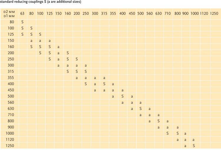
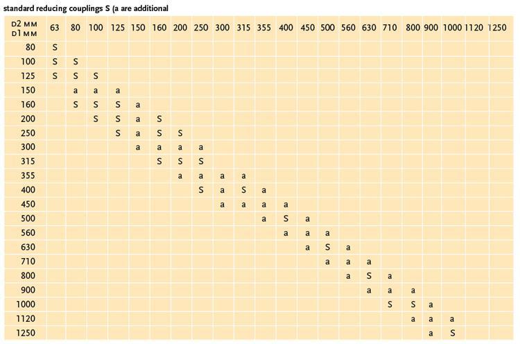
23 segmented construction with a tolerance of ±2. Segmented bends 45 shall consist of at least 3 segments. A.3.08 reducing couplings Reducing couplings may be either symmetrical or asymmetrical, with an upper angle of minimum 15 and maximum 60. Pressed reducing couplings may have a maximum upper angle of 90. Symmetrical reducing couplings shall be used as standard.
24
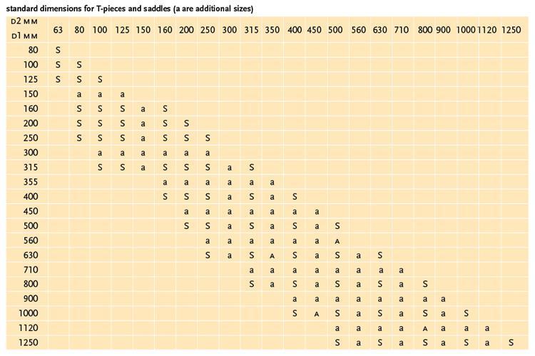
25 A.3.09 branches A branch (a take-off in an ongoing section of main duct) can be made by means of a: saddle piece, in combination with a straight tube; T-piece, as a complete fitting; 4-way coupling, as a complete fitting; and can be implemented as standard at an angle of 90 or 45. For technical reasons, angles < 45 should be avoided.
26

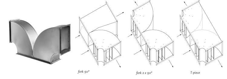
27 A.3.10 forks A fork is a subdivision of a main duct into two ongoing ducts. breech (Y-piece); inverted T-piece. If a breech is used, the fork can be made at an angle α = 90 or 60. If an inverted T-piece is used, the fork can be made at an angle α = 180. A.3.11 coupling pieces These are used as standard in: - joints between adjacent tubes; This fitting, made of the same material as the tubes and provided with a buffer edge, creates an internal joint.

28 - joints between adjacent fittings; This fitting, made of the same material as the tubes, is of smooth construction and creates an external joint. The insert length of the fittings shall be based on EN For overlaps, the following minimum lengths shall apply: The joints shall be fixed using self-tapping screws and finished with: tape with synthetic rubber mass (= self-vulcanising shrink tape); PVC tape: only for exhaust ducts; aluminium tape: only for exhaust ducts; linen tape: only for exhaust ducts; reinforced PE tape with acrylic adhesive mass; 2-component strip These tapes must be applied in accordance with the supplier s recommendations. When round fittings with a rubber seal (so-called Safe ) are used, the finishing with tape shall normally be omitted in the case of once-only installation.


29 A.3.12 adjustable dampers Adjustable dampers serve for the regulation of an installation and shall be made manually adjustable. They shall be provided with a reliable securing device, which also shows the damper setting. For surface areas up to 0.3 m2, the damper blade, made of the same material as the air duct, shall be made of singlethickness sheet. If the surface area is greater, the blade shall either be made of double-thickness sheet or be reinforced. The dampers shall be provided with reliable and airtight bearings. Perforated damper blades should be avoided. A 3.13 end covers Covers shall be made of the same material as the tubes.
30 A.3.14 tolerances The maximum tolerance for the length of a duct is ±0.005 x L. The tolerance for the diameters is specified in the adjacent table. The maximum tolerance for angles is ±2.

31 B.1.00 Rectangular aluminium ducts B.1.01 sheet quality For manufacturing rectangular aluminium air ducts, sheet material of Al 99.5 / EN AW 1050A quality shall generally be used. For specific applications, seawater-resistant aluminium of AlMg3 / EN AW 5754 quality can be used. B.1.02 sheet thickness Aluminium air ducts shall be made in a sheet thickness that is dependent upon the largest duct side. The air ducts shall be manufactured at this thickness to ensure sufficient rigidity against distortion and to prevent disturbing vibrations. Based on the largest duct side, the following apply as minimum sheet thicknesses: For technical reasons, thicknesses greater than 1.50 mm shall be avoided.
32 B.1.03 transverse joints For rectangular air ducts, various types of transverse joints can be used. These are company dependent, the quality of the sheet material from which the joint profiles shall be formed at least satisfying the requirements of the material from which the duct is manufactured. These transverse joints can (depending on the company) be attached to the duct by rolling, or fastened to the duct by means of projection welds, spot welds, screws or pop rivets. The transverse joints shall be coupled with clips, slide plates or clamps at a maximum centre-to-centre distance of 500 mm (see drawing). These fasteners shall be made of aluminium / stainless steel. To provide airtightness, a closed-cell sealing tape shall be applied between the transverse joints, the minimum dimensions being 18 x 4 mm (W x H) and all four corners being provided with stainless steel bolts and nuts of at least size M6 x 20. If slide plates are used over the whole perimeter of the duct, the bolts and nuts at the corners may be omitted. Where necessary, to provide airtightness, permanently plastic sealant shall be applied internally or externally.

33 B.1.04 longitudinal joints In principle, longitudinal joints between duct sections shall be made as a folded seam. Where necessary, to provide airtightness, permanently plastic sealant shall be applied internally or externally.

34 B.1.05 reinforcements Air ducts shall be made with a rigidity sufficient to prevent disturbing vibrations and distortion. Assuming that the recommended minimum sheet thickness according to B.1.02 is used, this applies to rectangular aluminium ducts when the largest side of the cross-section is 400 mm. Additional provisions are required when this dimension is exceeded. The amount of the excess shall determine the necessary provisions. For ducts with a side dimension of > 400 mm to 800 mm, the duct walls shall be made as follows: cross-breakings: crosswise embossments normally directed outwards; corrugations or folds: usually made at right-angles to the longitudinal axis of the duct at a mutual distance not exceeding 500 mm. For ducts with a side dimension > 800 mm, the previously mentioned provisions for the duct walls apply, surfaces with an area greater than 1.5 m2 being additionally reinforced by partitioning into subsections not greater than 1 m2. These additional reinforcements shall be fitted internally or externally in the form of strips, profiles, tubes or plates. B.1.06 dimensions The nominal dimensions of the air ducts shall be given in mm and refer to the inside dimensions with a tolerance of +0 to -4 mm. The dimensions shall be standardised according to EN 1505 and can be selected as indicated in the table of standard dimensions.

35 B.1.07 exposed ductwork If a section of the air duct system in an air-conditioning installation is intended as "exposed ductwork", it shall be constructed as the rest of the ductwork, unless otherwise specified. When ductwork is intended as exposed ductwork, external stickers and labelling shall be removed, while the required airtightness shall be obtained by internal application of sealant. Additional measures in the context of exposed ductwork are not normally included in the standard construction. B.1.08 bends
 To limit the friction in a bend, the bends shall be provided with vanes.")
36 B symmetrical bends In principle, symmetrical bends have a round shape, i.e. with an inside and an outside radius; the inside radius shall be at least 100 mm. (For floor or wall openings where there is no room for an inside radius, a right-angled inside bend can be used.) To limit the friction in a bend, the bends shall be provided with vanes. Vanes are not required in the following cases: a bend of 45 or less; duct with a width of 400 mm or less. The vanes shall be positioned according to the following table. B reducing bends In the case of reducing bends, the smallest duct width shall determine the number of vanes according to the above table. The ratio for the position of the vanes at the largest duct width is then equal to the ratio for the vanes at the smallest duct width.
37 B construction of vanes Vanes shall be made of single-thickness sheet. The sheet material shall be the same as that used for the duct. The construction and fastening shall be of sufficient strength, and the ends of the vanes shall be reinforced. B.1.09 reducing couplings Reducing couplings shall be made in such a way that the upper angle α may in principle be 60 maximum. B.1.10 branches A branch (a take-off in an ongoing section of main duct) can be made by means of a fitting, either rectangular or round. Technical aspects of air flow design codetermine the type, as shown in the drawings below.
38 B.1.11 forks A fork is a subdivision of a main duct into two ongoing ducts. Examples of forks are:
39
40 B.1.12 adjustable dampers Adjustable dampers serve for the regulation of an installation and shall be made manually adjustable. They shall be provided with a reliable securing device, which also shows the damper setting. The damper blade, made of the same material as the air duct, shall be made of single-thickness sheet with a thickness of at least 1.25 mm, a maximum blade width (B) of 500 mm and a maximum surface area of 0.25 m2. The edges of the damper blades shall be rounded and reinforced parallel to the axis. B.1.13 tolerances The maximum tolerance for the length of a straight duct is ±0.005 x L. The tolerance for the rectangular dimensions is +0 to -4 mm. The maximum tolerance for angles is ±2.

41 B.2.00 Round aluminium ducts B.2.01 sheet quality For manufacturing round aluminium air ducts, sheet material of AlMg3 / EN AW 5754 Mill Finish quality according to EN 573/485 shall be used. B.2.02 sheet thickness B tubes Aluminium air ducts shall be made in a sheet thickness that is dependent upon the diameter, as specified below. Based on the diameter, the following apply as minimum sheet thicknesses in standard implementations:: B fittings
42 Fittings shall be made in a sheet thickness that is dependent upon the diameter. Based on the diameter, the following apply as minimum sheet thicknesses in standard implementations: B.2.03 joints in tubes The joints in the spiral-wound strip shall be made as a flat folded seam, providing sufficient rigidity and airtightness. B.2.04 joints in fittings The seam joints in fittings shall be made in such a way that sufficient rigidity and airtightness are obtained. These joints shall be made by welding or folding. B.2.05 tube length
43 Tubes shall be supplied in standard lengths of 3000 or 6000 mm. For technical reasons, tube lengths shall in principle be not less than the tube diameter, with a minimum length of 300 mm. B.2.06 diameters The tubes shall be made in standard diameters according to EN 1506, namely and 1250 mm. Additional sizes stated in EN 1506 are: mm. B.2.07 bends With the exception of diameters of 63 and 80 mm, for which the curve radius shall be 100 mm, the shape of bends shall normally be determined by a radius, measured across the centre of the bend, that is equal to the tube diameter. Standard bends shall have angles of 15, 30, 45, 60 and 90 in segmented construction with a tolerance of ±2. Segmented bends of 45 shall consist of at least 3 segments. B.2.08 reducing couplings Reducing couplings may be either symmetrical or asymmetrical, with an upper angle of minimum 15 and maximum 60. Pressed reducing
44 couplings may have a maximum upper angle of 90. Symmetrical reducing couplings shall be used as standard.
45 B.2.09 branches A branch (a take-off in an ongoing section of main duct) can be made by means of a: saddle piece, in combination with a straight tube; T-piece, as a complete fitting; 4-way coupling, as a complete fitting; and can be implemented as standard at an angle of 90 or 45. For technical reasons, angles < 45 should be avoided.
46
47 B.2.10 forks A fork is a subdivision of a main duct into two ongoing ducts. It can be made by means of a: breech (Y-piece); inverted T-piece. If a breech is used, the fork can be made at an angle α = 90 or 60. If an inverted T-piece is used, the fork can be made at an angle α = 180. B.2.11 coupling pieces

48 These are used as standard in: joints between adjacent tubes; This fitting, made of the same material as the tubes and provided with a buffer edge, creates an internal joint. joints between adjacent fittings; This fitting, made of the same material as the tubes, is of smooth construction and creates an external joint. The insert length of the fittings shall be based on EN For overlaps, the following minimum lengths shall apply:/p> The joints shall be fixed using self-tapping screws and finished with: tape with synthetic rubber mass (= self-vulcanising shrink tape); PVC tape: only for exhaust ducts; aluminium tape: only for exhaust ducts; linen tape: only for exhaust ducts; reinforced PE tape with acrylic adhesive mass; 2-component strip.
 are used, the finishing with tape shall normally be omitted in the case of onceonly installation. B.2.")
49 These tapes must be applied in accordance with the supplier s recommendations. When round fittings with a rubber seal (so-called Safe ) are used, the finishing with tape shall normally be omitted in the case of onceonly installation. B.2.12 adjustable dampers Adjustable dampers serve for the regulation of an installation and shall be made manually adjustable. They shall be provided with a reliable securing device, which also shows the damper setting. For surface areas up to 0.3 m2, the damper blade, made of the same material as the air duct, shall be made of single-thickness sheet. If the surface area is greater, the blade shall either be made of doublethickness sheet or be reinforced. The dampers shall be provided with reliable and airtight bearings. Perforated damper blades should be avoided.
50 B.2.13 end covers Covers shall be made of the same material as the tubes. B.2.14 tolerances The maximum tolerance for the length of a duct is ±0.005 x L. The tolerance for the diameters is specified in the adjacent table. The maximum tolerance for angles is ±2.
51 C.1.00 Rectangular stainless steel ducts C.1.01 sheet quality For manufacturing rectangular stainless steel air ducts, sheet of X 5 CrNi quality according to EN (AISI 304) shall generally be used. For specific applications, stainless steel of X 5 CrNi quality according to EN (AISI 316) can be used. C.1.02 sheet thickness Stainless steel air ducts shall be made in a sheet thickness that is dependent upon the largest duct side, as specified below. The air ducts shall be manufactured at this thickness to ensure sufficient rigidity against distortion and to prevent disturbing vibrations. Based on the largest duct side, the following apply as minimum sheet thicknesses: For technical reasons, thicknesses greater than 1.00 mm shall be avoided. C.1.03 transverse joints
52 For rectangular air ducts, various types of transverse joints can be used. These are company dependent, the quality of the sheet material from which the joint profiles shall be formed at least satisfying the requirements of the material from which the duct is manufactured. These transverse joints can (depending on the company) be attached to the duct by rolling, or fastened to the duct by means of projection welds, spot welds, screws or pop rivets. The transverse joints shall be coupled with clips, slide plates or clamps at a maximum centre-to-centre distance of 500 mm (see drawing). These fasteners shall be made of stainless steel. To provide airtightness, a closed-cell sealing tape shall be applied between the transverse joints, the minimum dimensions being 18 x 4 mm (W x H) and all four corners being provided with stainless steel bolts and nuts of at least size M6 x 20. If slide plates are used over the whole perimeter of the duct, the bolts and nuts at the corners may be omitted. Where necessary, to provide airtightness, permanently plastic sealant shall be applied internally or externally.
53 C.1.04 longitudinal joints
54 In principle, longitudinal joints between duct sections shall be made as a folded seam. Where necessary, to provide airtightness, permanently plastic sealant shall be applied internally or externally. C.1.05 reinforcements Air ducts shall be made with a rigidity sufficient to prevent disturbing vibrations and distortion. Assuming that the recommended minimum sheet thickness according to C.1.02 is used, this applies to rectangular metal ducts when the largest side of the crosssection is 400 mm. Additional provisions are required when this dimension is exceeded. The amount of the excess shall determine the necessary provisions.. For ducts with a side dimension of > 400 mm to 800 mm, the duct walls shall be made as follows: - cross-breakings: crosswise embossments normally directed outwards; - corrugations or folds: usually made at right-angles to the longitudinal axis of the duct at a mutual distance not exceeding 500 mm. For ducts with a side dimension > 800 mm, the previously mentioned provisions for the duct walls apply, surfaces with an area greater than 1.5 m2 being additionally reinforced by partitioning into subsections not greater than 1 m2. These additional reinforcements shall be fitted internally or externally in the form of strips, profiles, tubes or plates. C.1.06 dimensions The nominal dimensions of the air ducts shall be given in mm and refer to the inside dimensions with a tolerance of +0 to -4 mm. The dimensions shall be standardised according to EN 1505 and can be selected as indicated in the table of standard dimensions.
55 C.1.07 exposed ductwork If a section of the air duct system in an air-conditioning installation is intended as exposed ductwork, it shall be constructed as the rest of the ductwork, unless otherwise specified. When ductwork is intended as exposed ductwork, external stickers and labelling shall be removed, while the required airtightness shall be obtained by internal application of sealant. Additional measures in the context of exposed ductwork are not normally included in the standard construction.
 To limit the friction in a bend, the bends shall be provided with vanes.")
56 C.1.08 bends C symmetrical bends In principle, symmetrical bends have a round shape, i.e. with an inside and an outside radius; the inside radius shall be at least 100 mm. (For floor or wall openings where there is no room for an inside radius, a right-angled inside bend can be used.) To limit the friction in a bend, the bends shall be provided with vanes.vanes are not required in the following cases: - a bend of 45 or less; - a duct with a width of 400 mm or less. The vanes shall be positioned according to the following table. C reducing bends In the case of reducing bends, the smallest duct width shall determine the number of vanes according to the above table. The ratio for the position of the vanes at the largest duct width is then equal to the ratio for the vanes at the smallest duct width.
57 C construction of vanes Vanes shall be made of single-thickness sheet. The sheet material shall be the same as that used for the duct. The construction and fastening shall be of sufficient strength, and the ends of the vanes shall be reinforced. C.1.09 reducing couplings VReducing couplings shall be made in such a way that the upper angle α may in principle be 60 maximum. C.1.10 branches A branch (a take-off in an ongoing section of main duct) can be made by means of a streamlined fitting, either rectangular or round. Technical aspects of air flow design codetermine the type, as shown in the drawings below.
58 C.1.11 forks A fork is a subdivision of a main duct into two ongoing ducts. Examples of forks are:
59
60 C.1.12 adjustable dampers Adjustable dampers serve for the regulation of an installation and shall be made manually adjustable. They shall be provided with a reliable securing device, which also shows the damper setting. The damper blade, made of the same material as the air duct, shall be made of single-thickness sheet with a thickness of at least 1.25 mm, a maximum blade width (B) of 500 mm and a maximum surface area of 0.25 m2. The edges of the damper blades shall be rounded and reinforced parallel to the axis. C.1.13 tolerances The maximum tolerance for the length of a straight duct is ±0.005 x L. The tolerance for the rectangular dimensions is +0 to -4 mm. The maximum tolerance for angles is ±2.
 shall be used. For specific applications, stainless steel of X 5 CrNi-18-10-1.")

61 C.2.00 Round stainless steel ducts C.2.01 sheet quality For manufacturing round stainless steel air ducts, sheet steel of X 5 CrNi quality according to EN (AISI 304) shall be used. For specific applications, stainless steel of X 5 CrNi quality according to EN (AISI 316) can be used. C.2.02 sheet thickness C tubes The stainless steel air ducts shall be made in a sheet thickness that is dependent upon the diameter, as specified below. Based on the diameter, the following apply as minimum sheet thicknesses in standard implementations:
62 C fittings Stainless steel fittings shall be made in a minimum sheet thickness of 0.6 mm. C.2.03 joints in tubes The joints in the spiral-wound strip shall be made as a flat folded seam, providing sufficient rigidity and airtightness. C.2.04 joints in fittings The seam joints in fittings shall be made in such a way that sufficient rigidity and airtightness are obtained. These joints shall be made by welding or folding. C.2.05 tube length Tubes shall be supplied in standard lengths of 3000 or 6000 mm. For technical reasons, tube lengths shall in principle be not less than the tube diameter, with a minimum length of 300 mm. C.2.06 diameters
63 The tubes shall be made in standard diameters according to EN 1506, namely and 1250 mm. Additional sizes stated in EN 1506 are: mm. C.2.07 bends With the exception of diameters of 63 and 80 mm, for which the curve radius shall be 100 mm, the shape of bends shall normally be determined by a radius, measured across the centre of the bend, that is equal to the tube diameter. Standard bends shall have angles of 15, 30, 45, 60 and 90 in segmented construction with a tolerance of ±2. Segmented bends of 45 shall consist of at least 3 segments. C.2.08 reducing couplings Reducing couplings may be either symmetrical or asymmetrical, with an upper angle of minimum 15 and maximum 60. Pressed reducing couplings may have a maximum upper angle of 90. Symmetrical reducing couplings shall be used as standard.
64
65

66 C.2.09 branches A branch (a take-off in an ongoing section of main duct) can be made by means of a: saddle piece, in combination with a straight tube; T-piece, as a complete fitting; 4-way coupling, as a complete fitting; and can be implemented as standard at an angle of 90 or 45. For technical reasons, angles < 45 should be avoided.
67

68 C.2.10 forks A fork is a subdivision of a main duct into two ongoing ducts. It can be made by means of a: breech (Y-piece); inverted T-piece. If a breech is used, the fork can be made at an angle α = 90 or 60. If an inverted T-piece is used, the fork can be made at an angle α = 180. C.2.11 coupling pieces These are used as standard in:

69 joints between adjacent tubes; This fitting, made of the same material as the tubes and provided with a buffer edge, creates an internal joint.. joints between adjacent fittings; This fitting, made of the same material as the tubes, is of smooth construction and creates an external joint. The insert length of the fittings shall be based on EN For overlaps, the following minimum lengths shall apply: The joints shall be fixed using self-tapping screws and finished with: tape with synthetic rubber mass (= self-vulcanising shrink tape); PVC tape: only for exhaust ducts; aluminium tape: only for exhaust ducts; linen tape: only for exhaust ducts; reinforced PE tape with acrylic adhesive mass;; 2-component strip. These tapes must be applied in accordance with the supplier s recommendations. When round fittings with a rubber seal (so-called Safe ) are used,

70 the finishing with tape shall normally be omitted in the case of onceonly installation. C.2.12 adjustable dampers Adjustable dampers serve for the regulation of an installation and shall be made manually adjustable. They shall be provided with a reliable securing device, which also shows the damper setting. For surface areas up to 0.3 m2, the damper blade, made of the same material as the air duct, shall be made of single-thickness sheet. The dampers shall be provided with reliable and airtight bearings. Perforated damper blades should be avoided. C.2.13 end covers
71 Covers shall be made of the same material as the tubes. C.2.14 tolerances The maximum tolerance for the length of a duct is ±0.005 x L. The tolerance for the diameters is specified in the adjacent table. The maximum tolerance for angles is ±2.
72 D.1.00 Rectangular plastic ducts D.1.01 sheet quality Durable and reliable air ducts are essential. Plastics score well in terms of these 2 criteria, and are therefore also highly suitable for ventilation applications. The following plastics are appropriate for the manufacture of air ducts: PVC, PVC-C, HDPE, PP and PP-S. These plastics are chemical- and corrosion-resistant. They are therefore also appropriate for the extraction of aggressive vapours and steam. In addition, they are maintenance-free and guarantee long life. PVCPVC is highly suitable for corrosive and aggressive conditions. It is processed by means of glue bonding or hot gas welding. PVC-C: PVC-C has high chemical resistance and a better temperature resistance than PVC. It is usually processed by means of glue bonding. HDPE: HDPE is an inert material that is highly resistant to abrasive and corrosive substances. HDPE has a very smooth surface and is fairly impact-resistant. It is usually processed by means of welding. PP en PP-S: The PP tubing for industrial purposes is supplied in a light grey-beige colour RAL Thin-wall PP tubes are used for low-pressure ventilation applications. PP-S is a low-combustibility polypropylene with self-extinguishing properties. The colour of these tubes is grey RAL These plastics are usually processed by means of welding.

73 D.1.02 wall thickness Plastic air ducts shall be made in a wall thickness that is dependent upon the largest duct side, as specified below. The air ducts shall be manufactured at this thickness to ensure sufficient rigidity against distortion. Based on the largest duct side, the following apply as minimum wall thicknesses: D.1.03 joints The various plastics shall be joined in the following ways: PVC: glue bonded, welded or mechanically joined; PVC-C: glue bonded or mechanically joined; HDPE: welded or mechanically joined; PP: welded or mechanically joined; PP-S: welded or mechanically joined.
74 D.1.04 transverse joints Transverse joints in adjacent air ducts shall be made by means of flanges formed from strip material or angle sections. The flanges shall be securely fastened to the ducts. The quality and thickness shall satisfy the same requirements as the material from which the duct is manufactured. Adjacent sections shall be connected with fasteners and sealing tape that are sufficiently chemical-resistant and provide sufficient airtightness. In all cases, transverse joints that are made internally by means of coupling pieces shall be welded. External coupling pieces shall always be welded if PP or HDPE is used, and shall also be glue bonded if PVC-C is used. If the duct side is 600 mm or greater, internal reinforcements shall also be fitted. Adjacent transverse joints shall be welded using expansion sleeves of soft PVC. D.1.05 longitudinal joints In principle, longitudinal joints between duct sections shall be welded. D.1.06 reinforcements Air ducts shall be made with a rigidity sufficient to prevent distortion. Assuming that the recommended minimum wall thickness according to D.1.02 is used, duct surfaces and duct sections with a width > 300m shall be reinforced. For ducts with a width > 600 mm, surfaces with an area greater than 1 m2 shall be additionally reinforced using externally or internally welded strips, or round spacer sleeves made from plastic conforming to the same specifications shall be fitted in the duct sections. For ducts with a width greater than 1000 mm, surfaces with an area greater than 0.7 m2 shall also be additionally reinforced.
75 D.1.07 types For the possible types of plastic air ducts, see D It is important that the choice of the material is made in consultation with the supplier. D.1.08 dimensions The nominal dimensions of the air ducts shall be given in mm and refer to the outside dimensions with a tolerance of ±2 mm up to and including a side length of 1000 mm. The dimensions shall be standardised as for the dimensions of rectangular metal ducts. D.1.09 exposed ductwork If a section of the air duct system in an air-conditioning installation is intended as exposed ductwork, it shall be constructed as the rest of the ductwork, unless otherwise specified. When ductwork is intended as exposed ductwork, external stickers and labelling shall be removed, while the required airtightness shall be obtained by internal application of sealant. Additional measures in the context of exposed ductwork are not normally included in the standard construction.
 To limit the friction in a bend, the bends shall be provided with vanes.")
76 D.1.10 bends D symmetrical bends In principle, symmetrical bends have a round shape, i.e. with an inside and an outside radius; the inside radius shall be at least 100 mm. (For floor or wall openings where there is no room for an inside radius, a right-angled inside bend may be used.) To limit the friction in a bend, the bends shall be provided with vanes. Vanes are not required in the following cases: a bend of 45 or less; a duct with a width of 400 mm or less. The vanes shall be positioned according to the following table. D reducing bends In the case of reducing bends, the smallest duct width shall determine the number of vanes, in accordance with the above table. The ratio for the position of the vanes at the largest duct width is then equal to the ratio for the vanes at the smallest duct width.
77 D construction of vanes Vanes shall be made of single-thickness sheet. The sheet material shall be the same as that used for the duct. The construction and fastening shall be of sufficient strength. D.1.11 reducing couplings Reducing couplings shall be made in such a way that the upper angle α may in principle be 60 maximum. D.1.12 branches A branch (a take-off in an ongoing section of main duct) can be made by means of a streamlined fitting, either rectangular or round. Technical aspects of air flow design co-determine the type, as shown in the drawings below.
78
79 D.1.13 forks A fork is a subdivision of a main duct into two ongoing ducts. Examples of forks are: D.1.14 adjustable dampers Adjustable dampers serve for the regulation of an installation and shall be made manually adjustable. They shall be provided with a reliable securing device, which damper setting. The damper blade, made of the same material as the air duct, shall be made of single-thickness sheet with a thickness of at least 4 mm, a maximum 400 mm and a maximum surface area of 0.20 m2.
80 D.1.15 smoke development, fire propagation and combustibility PVC: low combustibility, self-extinguishing in accordance with DIN 4102/Class B1 PVC-C: low combustibility, self-extinguishing in accordance with DIN 4102/Class B1 HDPE: normal combustibility, non-self-extinguishing in accordance with DIN 4102/Class B2 PP: normal combustibility, non-self-extinguishing in accordance with DIN 4102/Class B2 PP-S: low combustibility, self-extinguishing in accordance with DIN 4102/Class B1 D.1.16 operating temperature The maximum operating temperature for PVC ducts is 60ºC.. The maximum operating temperature for PVC-C ducts is 90ºC. The maximum operating temperature for HDPE ducts is 70ºC. The maximum operating temperature for PP ducts is 100ºC. The maximum operating temperature for PP-S ducts is 100ºC.
81 D.2.00 Round plastic ducts D.2.01 sheet quality Durable and reliable air ducts are essential. Plastics score well in terms of these 2 criteria, and are therefore also highly suitable for ventilation applications. The fo appropriate for the manufacture of air ducts: PVC, PVC-C, HDPE, PP and PP-S. These plastics are chemical- and corrosion-resistant. They are therefore also appr extraction of aggressive vapours and steam. In addition, they are maintenance-free and guarantee long life. PVC: PVC is highly suitable for corrosive and aggressive conditions. The colour of PVC tubes is grey RAL PVC is processed by means of glue bonding or PVC-C: PVC-C has high chemical resistance and a better temperature resistance than PVC. It is usually processed by means of glue bonding. HDPE:HDPE is an inert material that is highly resistant to abrasive and corrosive substances. HDPE has a very smooth surface and is fairly impact-resistant. It is means of welding. PP en PP-S:The PP tubing for industrial purposes is supplied in a light grey-beige colour RAL Thin-wall PP tubes are used for low-pressure ventilation app low-combustibility polypropylene with self-extinguishing properties. The colour of these tubes is grey RAL These plastics are usually processed by means o D.2.02 wall thickness The tubes and fittings shall be made in a wall thickness that is dependent upon the diameter, with a minimum thickness of 1.8 mm. D.2.03 joints

82 The various plastics shall be joined in the following ways: PVC: glue bonded, welded or mechanically joined; PVC-C: glue bonded or mechanically joined; HDPE: welded or mechanically joined; PP: welded or mechanically joined; PP-S: welded or mechanically joined. The fittings shall have sleeve couplings as standard. D.2.04 tube length To avoid difficulties in transport and handling, standard tubes shall be supplied up to a maximum length of 5000 mm with a tolerance of ±0.005 x L. D.2.05 diameter/tolerances
83 D.2.06 bends With the exception of diameters of 63 and 80 mm, for which the curve radius shall be 100 mm, the shape of bends shall normally be determined by a radius, measu of the bend, that is equal to the tube diameter. Standard bends shall have angles of 15, 30, 45, 60 and 90 in pressed or segmented construction with a tolerance bends 45 shall consist of at least 3 segments. D.2.07 reducing couplings Reducing couplings may be either symmetrical or asymmetrical, with an upper angle of minimum 15 and maximum 60. Symmetrical reducing couplings shall b D.2.08 branches and forks
84 A branch (a take-off in an ongoing section of main duct) can be made by means of a T-piece, as a complete fitting, and can be implemented as standard at an angle A fork is a subdivision of a main duct into two ongoing ducts. Examples of branches and forks are: D.2.09 adjustable dampers
85 Adjustable dampers serve for the regulation of an installation and shall be made manually adjustable. They shall be provided with a reliable securing device, which damper setting. The damper blade, made of the same material as the air duct, shall be made of single-thickness sheet with a thickness of at least 3 mm up to a max mm. The dampers shall be provided with reliable and airtight bearings. D.2.10 smoke development, fire propagation and combustibility PVC: Low combustibility, self-extinguishing in accordance with DIN 4102/Class B1 PVC-C: low combustibility, self-extinguishing in accordance with DIN 4102/Class B1 HDPE: normal combustibility, non-self-extinguishing in accordance with DIN 4102/Class B2 PP: normal combustibility, non-self-extinguishing in accordance with DIN 4102/Class B2 PP-S: low combustibility, self-extinguishing in accordance with DIN 4102/Class B1 D.2.11 operating temperature The maximum operating temperature for PVC ducts is 60ºC. The maximum operating temperature for PVC-C ducts is 90ºC. The maximum operating temperature for HDPE ducts is 70ºC. The maximum operating temperature for PP ducts is 100ºC. The maximum operating temperature for PP-S ducts is 100ºC.
86 E.1.00 Rectangular mineral wool ducts E.1.01 panel quality Mineral wool ducts shall be made in the following minimum density: - glass wool 78 kg/m3 with a tolerance of 5%; - rock wool 150 kg/m3 with a tolerance of 5%. E.1.02 panel thickness Mineral wool air ducts shall be made in the following minimum panel thickness: glass wool 22 mm with a tolerance of +1 mm; glass wool 22 mm with a tolerance of +1 mm; rock wool 20 mm with a tolerance of +1 mm. The air ducts shall be manufactured at this thickness to ensure sufficient rigidity against distortion.
87 E.1.03 transverse joints Transverse joints between adjacent air ducts shall be made: by means of profiles formed from sheet steel of DX 51 DZ 275 MAC quality, coated on both sides with a zinc layer according to the Sendzimir process. The layer thickness shall be 275 g/m2 for both sides, measured according to the trihedral test. Sheet quality / zinc quality shall be in accordance with EN 10142, and tolerances shall be in accordance with EN The sheet steel profiles shall be securely fastened to the ducts. E.1.04 longitudinal joints Longitudinal joints shall be made as a profiled seam, and finished with an aluminium tape with a minimum width of 75 mm in the case of ducts with an aluminium outer layer. E.1.05 reinforcements Air ducts shall be made with a rigidity sufficient to prevent distortion. Assuming that the recommended minimum panel thickness according to E.1.02 is used, duct surfaces with a width > 600 mm in the case of glass wool and > 1200 mm in the case of rock wool shall be strengthened internally with reinforcements of galvanised material. These shall be attached to the duct surfaces using screws with washers. The number of reinforcement profiles shall be: 1 per 0.75 m2 wall surface in the case of glass wool and 1 per 1.25 m² wall surface in the case of rock wool. E.1.06 dimensions
88 The nominal dimensions of the air ducts shall be given in mm and refer to the inside dimensions with a tolerance of +2 mm for a side length 1200 mm, and +4 mm for a side length > 1200 mm. The dimensions shall be standardised as for the dimensions of rectangular metal ducts. E.1.07 types The possible types of mineral wool air ducts are: rock wool with cement outer layer, suitable for indoor use; glass wool with 100-micron aluminium foil outer layer, suitable for indoor use; glass wool with polyester outer layer, suitable for outdoor use; glass wool with 100-micron aluminium inner facing and polyester outer layer, suitable for outdoor use. For the use of polyester, the following specifications are applicable: o o 450 g/m2 glass fibre for an inside duct size < 700 mm; - 2 x 450 g/m2 glass fibre for an inside duct size 700 mm. E.1.08 exposed ductwork If a section of the air duct system in an air-conditioning installation is intended as exposed ductwork, it shall be constructed as the rest of the ductwork, unless otherwise specified. When ductwork is intended as exposed ductwork, external stickers and labelling shall be removed, while the required airtightness shall be obtained by internal application of sealant. Additional measures in the context of exposed ductwork are not normally included in the standard construction.
89 E.1.09 bends Bends shall be implemented as: bends with an angle > 45º must be provided with vanes; right-angled bends shall be provided with vanes or air turns. E.1.10 reducing couplings
90 Reducing couplings shall be made in such a way that the upper angle may in principle be 60 maximum. E.1.11 branches A branch (a take-off in an ongoing section of main duct) can be made by means of a straight or streamlined fitting at an angle of 90. Technical aspects of air flow design co-determine the type of implementation. E.1.12 adjustable dampers Adjustable dampers serve for the regulation of an installation and shall be made manually adjustable. They shall be provided with a reliable securing device, which also shows the damper setting. The damper blade, made of galvanised material, shall be made of singlethickness sheet with a thickness of at least 1.5 mm up to a maximum blade width (B) of 500 mm and a maximum surface area of 0.25
91 m2. The edges of the damper blades shall be rounded and reinforced parallel to the axis. If the surface area is greater, different types of dampers must be used. E.1.13 erosion resistance In order to guarantee resistance to erosion, the ducts shall be finished internally with baked glass fibre or aluminium, depending on the application. The air speed at any place in the duct system must never exceed 12 m/s. E.1.14 smoke development, fire propagation and combustibility Mineral wool ducts must be non-combustible and must comply as a minimum with Class A2 of DIN 4102 and Class 1 NEN Smoke-developed index 1 (smoke density negligible in accordance with NEN 6066). E.1.15 allowable system pressure The maximum allowable system pressure is: for rectangular glass wool ducts with an aluminium outer layer 500 Pa; for rectangular glass wool ducts with a polyester outer layer 750 Pa; for octagonal glass wool ducts with a polyester outer layer 1000 Pa; for rectangular rock wool ducts 850 Pa.. E.1.16 operating temperature The maximum operating temperature for glass wool ducts and rock wool ducts with steel profiles is 120 C.
92 F.1.00 Rectangular rigid foam ducts F.1.01 panel quality Rigid foam air ducts shall be made from panels with a minimum density of 40 kg/m3. These panels shall have aluminium foil with a thickness of 60 microns on one side or both sides. F.1.02 panel thickness Rigid foam air ducts shall be made in the minimum panel thickness of 20 mm for phenolic foam, and 20 mm for PIR foam. The air ducts shall be manufactured at this thickness to ensure sufficient rigidity against distortion. F.1.03 transverse joints Transverse joints of air ducts shall be made in such a way that sufficient airtightness is obtained.
93 F.1.04 longitudinal joints The ducts shall be made from a flat panel, with V grooves cut at the corner. These grooves shall be glued. The closing sides shall be cut off at 45, glued and finished with an aluminium tape with a minimum width of 50 mm, and if necessary provided with e.g. joint clamps.
94 F.1.05 reinforcements Air ducts shall be made with a rigidity sufficient to prevent distortion. Assuming that the minimum panel thickness according to F.1.02 is used, duct surfaces > 700 mm shall be internally reinforced. F.1.06 types Some possible types of rigid foam air ducts are:: phenolic foam with aluminium outer layer and glass fibre inner facing, suitable for indoor use; phenolic foam with aluminium outer layer and aluminium inner facing, suitable for indoor use; phenolic foam with polyester outer layer and aluminium inner facing, suitable for outdoor use; PIR foam with aluminium outer layer and aluminium inner facing, suitable for indoor use; PIR foam with polyester outer layer and aluminium inner facing, suitable for outdoor use.
95 For the use of polyester, the following specifications are applicable: 450 g/m2 glass fibre for an inside duct size < 700 mm; 2 x 450 g/m2 glass fibre for an inside duct size 700 mm. F.1.07 dimensions The nominal dimensions of the air ducts shall be given in mm and refer to the inside dimensions with a tolerance of +2 mm for a side length 1200 mm, and +4 mm for a side length > 1200 mm. The dimensions shall be standardised as for the dimensions of rectangular metal ducts. F.1.08 exposed ductwork If a section of the air duct system in an air-conditioning installation is intended as exposed ductwork, it shall be constructed as the rest of the ductwork, unless otherwise specified. When ductwork is intended as exposed ductwork, external stickers and labelling shall be removed, while the required airtightness shall be obtained by internal application of sealant. Additional measures in the context of exposed ductwork are not normally included in the standard construction. F.1.09 bends Bends shall be implemented as: bends with an angle > 45º must be provided with vanes; right-angled bends shall be provided with vanes or air turns.
96
97 F.1.10 reducing couplings Reducing couplings shall be made in such a way that the upper angle α may in principle be 60 maximum. F.1.11 branches A branch (a take-off in an ongoing section of main duct) can be made by means of a straight or streamlined fitting at a maximum angle of 90. Technical aspects of air flow design co-determine the type of implementation.
98 F.1.12 adjustable dampers Adjustable dampers serve for the regulation of an installation and shall be made manually adjustable. They shall be provided with a reliable securing device, which also shows the damper setting. The damper blade, made of galvanised material, shall be made of singlethickness sheet with a thickness of at least 1.5 mm up to a maximum blade width (B) of 500 mm and a maximum surface area of 0.25 m2. The edges of the damper blades shall be rounded and reinforced parallel to the axis.
99 F.1.13 erosion resistance In order to guarantee resistance to erosion, the ducts shall be finished internally with baked glass fibre or aluminium, depending on the application. The air speed at any place in the duct system must never exceed 12 m/s. F.1.14 allowable system pressure The maximum allowable system pressure is 750 Pa. F.1.15 operating temperature The maximum operating temperature for rigid foam ducts with steel profiles is 110 C.

100 G.1.00 Round flexible ducts, or hoses G.1.01 material options Hoses shall be available in the following materials: aluminium;; aluminium foil; plastic. G.1.02 types of flexible hoses Hoses shall be available in three types: non-insulated; thermally-insulated acoustically-insulated G.1.03 non-insulated hose A non-insulated hose shall have a wall made of the material specified in G.1.01 and shall be provided with a horizontal steel spiral, covered or uncovered. The spiral can be provided with a coating.
101 G.1.04 thermally insulated hose A thermally insulated hose shall have an inner hose as specified in non-insulated hose. The hose shall be wrapped with thermally insulating material, such as glass wool or rock wool. Around the insulation, an outer jacket of reinforced aluminium polyester laminate shall be fitted, which may be provided with a steel spiral. G.1.05 acoustically insulated hose A spiral-reinforced inner hose of glass fibre mesh, wrapped with an acoustic material, such as glass wool or rock wool. Around the insulation, an outer jacket of reinforced aluminium laminate or plastic foil shall be fitted, which may be provided with a steel spiral. Between the inner hose and the insulation, a foil layer can optionally be fitted, to prevent particles of the insulation from entering the duct. G.1.06 length of flexible hoses Flexible hoses shall usually be supplied in compressed form. The hose must be extended before use. After the hose has been extended, its length must not be more than 3% shorter than the nominal length stated by the supplier. The available lengths vary from one manufacturer to another, and shall be available in lengths from 1 m to 10 m in the extended condition. In the compressed condition, the lengths are from 0.4 m to 3 m, depending on the type of hose. G.1.07 diameters The flexible ducts shall be made in standard diameters that are stated in EN 13180, see the table on the left. G.1.08 installation instructions For the installation of hoses, see section L installation instructions for flexible hoses.

102 G.2.00 Flexible aluminium hoses G.2.01 material quality Flexible aluminium ducts shall be manufactured from: aluminium strip in accordance with EN 573. G.2.02 wall thickness The thickness of the material is dependent upon the type of hose and the supplier. The minimum strip thickness shall be mm. G.2.03 joints in flexible hoses The joints in the spiral-wound strip shall be made as a folded seam, providing sufficient rigidity and airtightness.
103 G.3.00 Flexible aluminium foil hoses G.3.01 material quality The hose shall be composed of layers of aluminium foil and polyester foil, or aluminium polyester laminate. The hose must comply with: NEN 6065, minimum Class 2/fire propagation. G.3.02 wall thickness The thickness of the material is dependent upon the type of hose and the supplier.
104 G.4.00 Flexible plastic hoses G.4.01 material quality The hose shall be manufactured from a fibre-reinforced synthetic fabric or from a vinyl-coated woven fabric. G.4.02 wall thickness The thickness of the material is dependent upon the type of hose and the supplier.
105 H.1.00 Internal and external coating of air ducts H.1.01 purpose of coating The purpose of coating is to protect the ductwork. This can be because there are aggressive substances in the air, for instance in the case of swimming baths. The fresh air used as supply air can also contain corrosion-promoting constituents. Coating can also take place with the aim of simplifying internal cleaning. For instance, in the case of mineral wool or rigid foam ducts that are used in the food industry. H.1.02 types of coating There are different types of coating with a variety of uses and instructions for use. Common types are: water-repellent bituminous coating; polyester coating; polyurethane coating; corrosion-resistant primer. In addition to the purpose of the coating, the type used is also determined by the nature of the air duct and the field of application. The nature of the duct can be divided into: rectangular mineral wool rectangular rigid foam; rectangular galvanised steel sheet; round galvanised steel sheet.

106 H.1.03 instructions for use The coating must be processed in accordance with the supplier s instructions for use.
107 I.1.00 Thermal insulation of rectangular and round air ducts I.1.01 internal insulation of rectangular air ducts Internal insulation can only be used for rectangular air ducts. For round air ducts, in principle it is only possible to use external insulation. However, to prevent contamination of the installation and other problems, it is very strongly recommended that air ducts should only be insulated externally. If the decision is nevertheless made to insulate rectangular ducts internally, the following materials can be used: - glass wool or rock wool blankets with long fibres and finished with protective foil to prevent the shedding of these fibres. The most common thicknesses are 0.5 or 1 (13 or 26 mm); - vulcanised synthetic elastomers, usually with self-adhesive foil with a thickness of between 10 and 25 mm, depending on the application and the manufacturer. I properties The insulation blankets must comply with the following requirements: non-combustible, in accordance with DIN 4102, Class 2 and fire propagation in accordance with NEN 6065, Class 1; smoke-developed index: 1 (smoke density negligible in accordance with NEN 6066). I processing of insulation blankets without self-adhesive foil The insulation blankets shall be glued into the duct with contact adhesive. The entire duct surface shall be glued using a roller or using spray adhesive. The contact adhesive can be used at a temperature of approx. 15 C. The duct wall must be dry, clean and grease-free to obtain good adhesion. For extra fastening, at least 2 self-stick insulation anchors, weld pins or split-pin insulation anchors with cover plate for each m2 of wall surface area must be fitted on the walls of the duct.
108 I finishing On the end edges of the duct, the insulation must be finished with galvanised sheet profiles or plastic profiles. This is to prevent the shedding of insulation after duct sections have been joined together. I.1.02 external insulation of rectangular and round air ducts External insulation can be classified into three sections: 1. thermal insulation using glass wool or rock wool blankets (see I.1.03); 2. thermal insulation using plastic foam rubber on the basis of synthetic rubber (elastomer) (see I.1.04); 3. thermal insulation using glass wool or rock wool blankets, finished with aluminium cladding (see I.1.05). I.1.03 het thermisch isoleren met behulp van glaswol- of steenwoldekens This type of insulation shall only be used indoors. Rectangular and round metal air ducts shall usually, depending on the application, be externally thermally insulated using robust glass wool or rock wool blankets with a thickness of 25 mm. These blankets are composed of upright fibres, the so-called lamella blanket, covered on one side with a foil of reinforced pure aluminium (thickness 0.02 mm). Lamella blankets are available with and without a self-adhesive foil. For rectangular ducts, the insulation shall be fitted against the insulation strip and finished on the suspension structure. The bracket that is used for round ducts shall be incorporated within the insulation. The suspension structure for rectangular ducts is then outside the insulation. For this purpose, an equivalent high-compression insulation strip shall be fitted between the suspension structure and the duct wall, and the seams shall be provided with a vapour-tight finish. There is also the possibility of placing the air ducts on MDF blocks with the same thickness as the insulation. In that case, however, the insulation must be inserted between the blocks (see L ). It is also possible to insulate the air ducts before installation. When this is done, the insulation is somewhat compressed in the suspension bracket; it must be ensured that the protective foil around the insulation does not tear.
109 I properties The lamella blankets must comply with the following requirements: non-combustible, in accordance with DIN 4102, Class 2 and fire propagation in accordance with NEN 6065, Class 1; smoke-developed index: 1 (smoke density negligible in accordance with NEN 6066). I processing of insulation blankets without self-adhesive foil The insulation blanket must be cut at the following length: For a rectangular duct: L = 2x (duct width + 2x insulation thickness) + 2x (duct height + 2x insulation thickness) + overlap. For a round duct: L = (diameter of duct + 2x insulation thickness) x overlap. I processing of insulation blankets with self-adhesive foil This insulation shall be used in badly ventilated spaces and, because of the absence of self-stick insulation anchors, for rectangular ducts installed as exposed ductwork up to a width of 1200 mm. The insulation must be cut at the following length: For a rectangular duct: L = 2x (duct width + 2x insulation thickness) + 2x (duct height + 2x insulation thickness) + overlap. For a round duct: L = (diameter of duct + 2x insulation thickness) x overlap.
110 I sticking and finishing for rectangular ducts (without foil) The lamella blankets shall be glued to the duct with contact adhesive. The entire duct surface shall be glued using a roller or using spray adhesive. The contact adhesive can be used at a temperature higher than approx. 0 C. The duct wall must be clean, dry and grease-free to obtain a good adhesion between the insulation and the duct wall. To ensure that the insulation does not become detached from the duct wall while the adhesive is drying, in the case of horizontally installed air ducts wider than 600 mm, at least 2 self-stick insulation anchors, weld pins or split-pin insulation anchors with cover plate for each m2 of wall surface area must be fitted on the underside and the side walls of the duct. In the case of vertically installed ducts, insulation anchors must be fitted on all walls wider than 600 mm. It is recommended that the insulation should be fitted precisely between the flange joints. If it is necessary to insulate the flanges, due to the danger of condensation on the flange, a separate strip must be fitted over the flange joint. The seams between the lamella blankets must be stuck together using an aluminium all-weather" tape, with a width of 75 mm and a minimum adhesion strength on steel of 9N/25 mm2, and then smoothed down. I sticking and finishing for rectangular ducts (with foil) After cutting the insulation to the right size, peel off the backing over approx. 10 cm longitudinally. The insulation must then be fitted in the right position and pressed down firmly over the entire surface area (NB: once the insulation has been pressed down, it cannot be moved again). After this, peel off the remaining backing in stages, and each time press the insulation down firmly against the duct wall over the entire surface area. It is recommended that the insulation should be fitted precisely between the flange joints. If it is necessary to insulate the flanges, due to the danger of condensation on the flange, a separate strip must be fitted over the flange joint. Ducts up to a width of 1200 mm do not need to be provided with self-stick insulation anchors, weld pins or split-pin insulation anchors. During the processing, the surrounding temperature must be between +10 C and +50 C. The seams between the lamella blankets must be stuck together using an aluminium all-weather" tape, with a width of 75 mm and a minimum adhesion strength on steel of 9N/25 mm2, and then smoothed down.
111 I sticking and finishing for round ducts For round air ducts, spray adhesive and/or contact adhesive shall not be used. The insulation must be cut at the right length and the overlap prepared by cutting the insulation away from the aluminium foil. The seams must then be stuck using the tape stated in I , and smoothed down. In addition, at intervals of 600 mm a pull-up strap with a width of at least 10 mm must be fixed around the insulation. I.1.04 thermal insulation using plastic foam rubber on the basis of synthetic rubber (elastomer) This method of insulation shall only be used indoors. Where there are greater temperature differences (e.g. fresh air supply ducts) or where the ducts are exposed, rectangular and round metal ducts shall be externally insulated using the above-mentioned insulation material. This material is available in various thicknesses, depending on the manufacturer and the temperature differences. This insulation material is available with and without a self-adhesive foil. To obtain correct insulation, the suspension structures shall be kept outside the insulation, for both rectangular and round ducts. In addition, a separate strip of the same insulation thickness shall always be glued over the duct flanges I properties The insulation must comply as a minimum with the following requirements: non-combustible, in accordance with DIN 4102, Class 2 and fire propagation in accordance with NEN 6065, Class 1; smoke-developed index: 1 (smoke density negligible in accordance with NEN 6066); practical reaction to fire: self-extinguishing, non-drip and non-fire-spreading.
112 I processing The insulation must be cut at the following length: For a rectangular duct: All the sides shall be cut to the size of the side + 1x insulation thickness. For a round duct: L = (diameter of duct + 2x insulation thickness) x I sticking and finishing For both rectangular and round air ducts, the insulation shall in principle be glued over the entire surface with the adhesive supplied with the insulation by the supplier. All buffer edges must be pressed down well, and therefore also glued well. This also applies for use of insulation with a self-adhesive layer. The surfaces to be glued must be dustfree and grease-free. This form of insulation does not need to be further finished with tapes or self-stick insulation anchors. I.1.05 thermal insulation using glass wool or rock wool blankets, finished with aluminium cladding I general For the fitting of the mineral wool blanket, see section I.1.03.
113 I fitting of aluminium cladding Externally insulated ducts that are located outdoors can be finished with (stucco) aluminium cladding. In coastal areas, the seawater-resistant quality (AlMg3 / EN AW 5754) is recommended for this. After the metal air ducts have been installed on the roof or against a wall in the open air, the external insulation of the required material and thickness shall be fitted. After this, the aluminium cladding shall be fitted. The thickness of the aluminium panel shall be a minimum of 0.8 mm. The cladding shall be fitted by overlapping the adjacent panels. These panels shall be provided with so-called corrugations, which shall be made in the panel approx. 20 to 25 mm from the end of the panel. These corrugations shall be placed on top of each other, and fastened together with at least 13 x 3 mm stainless steel sheet-metal screws (8 screws/m). The cladding shall be fitted closely over the insulation, overlapping and draining in such a way that rainwater cannot enter or leak in. For this purpose, all seam joints in the panelling shall be provided with rain-tight sealing during or after installation of the aluminium cladding, using transparent silicon sealant. In order to obtain a rigid whole (especially in the case of larger ducts), aluminium strengthening strips can be fastened to the duct when it is being insulated. The aluminium cladding can then be fixed to these strips. If this is done, care must be taken that the aluminium strips are not fastened directly to the steel, because of the danger of electrolytic corrosion. A solution for this is to apply sealant, paint or tape between the duct and the strengthening strip.
114 J.1.00 Fire-resistant insulation and sheathing of metal air ducts J.1.01 air ducts and fire compartments Fire compartments can be classified into: fire compartments; smoke compartments. J fire compartments Air duct systems must comply with fire compartment requirements, as set down in the Dutch Buildings Decree (Bouwbesluit). When an air duct passes through a fire compartment, a fire damper must be used, which as a minimum is equal to the fire resistance of the partition in which it is located. Fusible links of the fire damper must be accessible by means of an inspection hatch or a removable servicing block. To prevent fire transfer via ventilation ducts, air ducts must be constructed in a fire-resistant manner, or a fire damper must be fitted at the position of a penetration of the partitioning construction. If it is not possible to fit fire dampers at the position of the penetration, the air duct section from the partitioning construction to the partition of the fire damper blade must be constructed in a fire-resistant manner, with a fire resistance equal to that of the partition concerned. The fire resistance of a fire damper must be demonstrated with a certificate of an accredited body. The following test methods are applicable for this: for fire-resistant ducts without fire dampers, in accordance with EN (NEN 6076); for fire-resistant ducts with fire dampers, in accordance with EN (NEN 6077). Identification and use of the correct standards The various suppliers offer products that have been approved in accordance with various standards. First of all, it is essential to always look at whether they say tested in accordance with or approved in accordance with. Both terms are found in the market, while only the
115 latter is at all meaningful. Suppliers of fire dampers, intumescent grilles and fire-resistant sleeves say that they conform to different standards, both NEN and EN. An explanation is given below of how this situation has arisen, and which standards are applicable. NEN standards Until a few years ago, in the Netherlands only the NEN standards were used, in particular: NEN 6069: Testing and classification of resistance to fire of building products and building elements; NEN 6077: Experimental determination of the fire resistance of ventilation ducts with dampers. Without quoting the texts of the standards in full, the following conclusions can be stated: NEN 6069: This standard covers the testing of e.g. intumescent grilles. Products that have been approved in accordance with this standard were tested in a non-pressure situation. An intumescent grille of this kind may then be used in e.g. a door or wall as an overflow provision. It is only permissible to use this product in air ducts if it is certain that the air-conditioning installation will switch off in the event of fire, guaranteeing that the intumescent grille will not be placed under pressure during a fire. After all, the product has not been tested for this, and therefore not approved. It should also be noted here that in the Netherlands in most cases the air-conditioning installation is used to remove smoke in the event of fire (to keep escape routes clear), which means that it is only permissible to use an intumescent grille in an air duct in a small number of cases. NEN 6077: This standard covers the testing of fire dampers. Fire dampers that comply with this standard were tested and approved under pressure, i.e. they may be used in air-conditioning installations without additional conditions being imposed. NEN-EN standards For some time, European standards have also been applicable, abbreviated as EN. In connection with fire-resistant products for airconditioning installations, EN 1366 is the most important standard. Given the European character, fire-resistant products no longer need to be tested in each country, even though the different countries take a different approach to the fire safety of installations. If a test laboratory is equipped to test in accordance with EN (the standard that gives the general requirements for the methods and equipment for conducting the test), it may conduct just one test to cover all European countries. A classification is then given on the basis of EN for ventilation products. The test leads to a test report, and on the basis of this a classification report is produced. In view of the above, it is
 the product concerned has been approved.")
116 therefore important that a supplier of fire-resistant products can provide the classification report, rather than the test report. After all, this contains the conclusion as to whether, and if so for how many minutes (15, 20, 30, 45, 60, 90, 120, 180, 240 or 360 minutes) the product concerned has been approved. This is always shown with: EIS xx, where xx is the number of minutes. The E stands for integrity, the I for insulation and the S for smoke leakage. For instance, EIS 60 indicates that the product concerned prevented the spread of smoke and insulated against heat, i.e. prevented it from spreading, for at least 60 minutes. EN 1366 makes the same distinction as the above-discussed NEN standards: EN : approval in accordance with this standard means that the product concerned was tested and approved under pressure. This is therefore the standard with which fire dampers tested after the NEN era must ideally comply. EN : a product with this approval was not tested under pressure, so has only be approved as e.g. an overflow provision between rooms. But definitely not for use in air ducts where it is not guaranteed that the air-conditioning installation will switch off in the event of fire. Conclusions and advice You should make sure that you use approved products, and not merely tested products. Then assess whether you only require a fireresistant provision in a non-pressure situation (the applicable old standard is NEN 6069, new standard is EN ); or if the situation involves pressure, then a product approved in accordance with the old standard NEN 6077 or the new standard EN must be used.t

117 J smoke compartments When an air duct passes through a smoke compartment, a fire damper must be used or the duct section that goes through this partition must be constructed over a distance of at least 3 metres without a break and without apertures (grilles). The 3 metres can be shifted in relation to the smoke partition. J.1.02 fire-resistant insulation of round air ducts If high fire-resistance requirements are imposed on the air flow path, it is recommended that rectangular air ducts should be constructed, in connection with the use of certified insulation materials. There is a product available in the trade, which is supplied with a thickness of 60 mm and, depending on the compression (weight per m2 of panel surface area), can be used for a 60-minute, 90-minute or 120-minute fire partition wall. Equivalent products can also be used, if a valid test report can be provided.

118 J.1.03 fire-resistant insulation of rectangular air ducts For this, the following insulation materials in the recommended thickness and type can be used: The insulation materials (fire boards) shall be fitted directly onto the air duct in accordance with the supplier s instructions. These boards shall usually be fixed using weld pins or screws. The boards shall be fastened to each other with a special type of adhesive. Non-combustible fibre silicate boards. Asbestos-free boards, manufactured from fibres, Portland cement and fillers, must be fitted in accordance with the manufacturer s instructions.
119 J.1.04 suspension of fire-resistant insulated air ducts Ducts must in principle be suspended as in the test method used in the standard. As a general guide, the following recommendations are made for this: maximum distance between the suspensions centre-to-centre 1.5 m; maximum weight per suspension point 50 kg; maximum allowable stress in threaded rods 9N/mm2 with a fire resistance of 30 and 60 minutes; maximum allowable stress in threaded rods 6 N/mm2 with a fire resistance of 90 and 120 minutes. Suspensions must be made so that the duct is fully clamped, by means of an upper bracket and lower bracket, and suspended by means of threaded rods of minimum M6 in metal plugs. This applies for both rectangular and round air ducts.
120
121 J.1.05 fire-resistant penetrations The test method for partitioning constructions with penetrations is laid down in the standards NEN 6069 and EN The finishing of penetrations can be done by: filling with structural material (e.g. mortar or plasterboard); filling with high-compression rock wool in combination with fire-resistant coating; filling with rock wool. The way in which the penetrations are finished depends on: material, shape and dimensions (diameter, wall thickness) of the air ducts; penetration sealing system; additional protection, such as intumescent coating, fire sleeves etc.; special fire-resistant sleeves that close the aperture by intumescence. Given that penetrations of several technical installations are combined at the position of the smoke and fire compartments, it is preferable to have this work done in combination by specialist companies. The co-ordination and responsibility should preferably lie with a construction partner.


122 J.1.06 installation of fire dampers The installation of fire dampers must be done in accordance with the manufacturer s instructions. When constructing a building, it is sometimes not possible to install the fire damper partially within the fire partition. If the fire damper cannot be installed in the fire partition wall, the duct section between the fire partition wall and the fire damper must be insulated in such a way that the quality of the fire partition is maintained. This shall preferably be done under the responsibility of the construction contractor.


123 K.1.00 Internal cleaning of air ducts K.1.01 general Air ducts must be transported carefully, to ensure that they remain as clean as possible. For the transport of round fittings, the use of packing material is recommended. At the construction site, ducts can be stored either in the open air or in the rough building structure. In both cases, the ducts must be stored on a dry base. It is recommended that the ducts should be protected against extreme weather conditions and contamination. While processing the ducts before and during installation, loose contaminants, such as dust, sand etc., in and on the duct shall be removed before the ducts are put in position. During the construction process, it is not possible for the air duct installation company to guarantee the internal cleanliness of the air ducts, for practical reasons. K.1.02 internal cleaning after the construction process has ended Within the scope of the environmental legislation, for the healthcare sector or for special production techniques, the requirement can be stated in the specifications that after the duct systems have been installed (preferably after the construction process has ended), they must be internally cleaned and provided with full certification. For this purpose, specialist companies have effective cleaning equipment and methods for testing and measuring in order to achieve the required level of cleanliness and to confirm this by means of a certificate.. It can also be advisable to clean the ducts after they have been in use for a number of years, or immediately after a fire (for instance, in relation to smoke). Given that Luka members do not have the required equipment and knowledge, this cleaning work is not normally included in their activities. In order to make the ducts accessible for the cleaning equipment, it is the responsibility of the consultant or the installation contractor to indicate on the air duct drawing the locations and dimensions of the inspection hatches or access hatches that are to
 In conjunction with TÜV Rheinland Nederland")
124 be fitted. If these provisions are not indicated on the drawing, the fitting of these is not included in the standard activities of the air duct manufacturer. K.1.03 The Netherlands Association of Air-conditioning System Cleaning Specialists (Nederlands Verbond Reinigingsspecialisten Luchtbehandelingssystemen, NVRL) In conjunction with TÜV Rheinland Nederland BV Bouw & Ondergrond (construction and foundations), the NVRL has developed a quality mark for the cleaning of air-conditioning systems. The quality mark is aimed at ensuring that air-conditioning systems and air ducts are kept clean, in order to restrict as far as possible the health risks due to contamination in these systems. The NVRL can be found at
125 L.1.00 Installation instructions L.1.01 general These installation instructions comply with the requirements of EN 1505, 1506 and Within the scope of the contract between Luka and TÜV Rheinland Nederland BV Certification, the instruction to check the manufacturing quality and installation quality has been given by TÜV Rheinland Nederland BV Certification to TÜV Rheinland Nederland BV. Safety, health and the environment are also important subjects in relation to installation activities. In accordance with the Working Conditions Act (Arbowet) and the Safety, Health & Environment Checklist for Contractors (VCA), the various parties involved in a construction project have their own specific responsibilities. For instance, the main contractor bears the final responsibility for the safety at the project and for providing general facilities and safety arrangements. The Luka members, as subcontractors, bear the responsibility for, among other things, the correct conduct of their employees and for providing them with the correct equipment. All this is usually set down in a project plan. The Luka members provide the principal or main contractor with their own company-specific project plan. This plan serves as part of the total project plan that will be formulated by the main contractor. Some important subjects in the project plan are: Toolbox meetings and instruction of employees. Fitters must have a valid VCA diploma. The use and availability of PPE (Personal Protective Equipment). Supervision at the site, including workplace safety inspections. The separation and orderly removal of waste. Use of approved tools and equipment. Safety, Health & Environment (SHE) co-ordinator.

126 The Luka members have their own company-specific safety or Occupational Health & Safety (OHS) system. In many cases, this system will be combined with the environmental management system and the quality assurance system. L.1.02 transport and storage Air ducts must be transported in a responsible manner, in such a way that transit damage is prevented. For the transport of round fittings, the use of boxes, net bags, bundles, crates or containers is recommended.. Air ducts are liable to distortion if handled carelessly or roughly. It is therefore essential to unload them with great care. Damage to joint profiles of rectangular ducts and to the edges of round ducts increases the likelihood of air leakage. To prevent damage as much as possible, it is recommended that the timing of the deliveries to the construction site should be closely co-ordinated with the progress of the installation. At the construction site, ducts can be stored either in the open air or in the rough building structure. In both cases, the ducts must be stored on a dry base. If they are stored in the open air, it is recommended that the ducts should be protected against extreme weather conditions and contamination. It is desirable that the air ducts and fittings, after being delivered to the construction site, should be stored as close as possible to the installation location, using a crane or builder s hoist to move them. L.1.03 installation instructions for rectangular and round air ducts At the start of each installation project, the lead fitter must have the installation drawings and/or material lists in his possession. The head of the installation team must also explain the installation instructions and the specific instructions applicable for the construction site.
127 L suspension and support of non-insulated rectangular metal ducts The air ducts shall be fastened or suspended in such a way that the duct sections and their accessories form a stable and rigid whole. The choice of materials and type of structure shall take account of the environmental conditions and the linear expansions of the duct material. The most frequently used structures are: consoles, galvanised or at least finished with zinc dust paint, used for attachment to structural fastening points; suspension structures that are strong enough to transfer the total weight of the air ducts, including the interposed accessories, to the structural suspension points via threaded rods; duct angle hangers with rubber insert. The suspension structure must be composed of a lower bracket made of Sendzimir galvanised material, provided with felt or P.E. tape with minimum dimensions of 18 x 4 mm, with threaded rods of at least M6 size mounted directly adjacent to the duct. The distance between these threaded rods shall be maximum 100 mm and minimum 30 mm greater than the duct width. The brackets shall have a maximum centre-to-centre distance between them of 3 m and can be made in either a formed profile or a standard trade profile that is strong enough to provide sufficient rigidity. (see table below) For shaft ducts, it is possible to use either consoles against the wall or profiles on the ducts, which are supported on the floor. The steel structures shall be made corrosion-resistant as a minimum. Roof ducts shall rest, by means of weather-resistant support profiles, on the roof provisions fitted by the construction contractor. These supports shall longitudinally have a maximum centre-to-centre distance of 2.5 m between them.
128 L suspension and support of rectangular plastic, mineral wool and rigid foam ducts Rectangular air ducts shall be fastened or suspended in such a way that the duct sections and their accessories form a stable and rigid whole. The choice of materials and type of structure shall take account of the environmental conditions and the linear expansions of the duct material. The most frequently used structures are: consoles, galvanised or at least finished with zinc dust paint, used for attachment to structural fastening points; suspension structures that are strong enough to transfer the total weight of the air ducts, including the interposed accessories, to the structural suspension points via threaded rods. The suspension structure must be composed of an upper bracket and lower bracket with threaded rods of at least M6 size mounted directly adjacent to the duct. The distance between these threaded rods shall be maximum 100 mm and minimum 30 mm greater than the duct width. The brackets shall have a maximum centre-to-centre distance between them of 3 m and must be made in either a formed profile or a standard trade profile that is strong enough to provide sufficient rigidity (see table in L ). For shaft ducts, it is possible to use either consoles against the wall or profiles on the ducts, which are supported on the floor. The steel structures shall be made corrosion-resistant as a minimum. Roof ducts shall rest, by means of weather-resistant or aluminium (AlMg3) support profiles, on the roof provisions fitted by the construction contractor. These supports shall longitudinally have a maximum centre-tocentre distance of 2.5 m between them.
129 Installation examples of non-insulated rectangular ducts
130
131 L suspension and support of insulated rectangular ductwork If the ducts are to be externally insulated after installation, MDF spacer blocks of 50 x 50 x 25 mm or high-compression insulation strips of 100 x 25 mm must be fitted between the lower bracket and the duct. This does not apply if the ducts are insulated before installation (socalled pre-insulation). Installation examples of insulated rectangular ductwork
132
133 L suspension and support of round metal ducts Round air ducts shall be fastened or suspended in such a way that the duct sections and their accessories form a stable and rigid whole. The choice of materials and type of structure shall take account of the environmental conditions and the linear expansions of the duct material. The most frequently used structures are: consoles, galvanised or at least finished with zinc dust paint, used for attachment to structural fastening points;; suspension structures that are strong enough to transfer the total weight of the air ducts, including the interposed accessories, to the structural suspension points via threaded rods. The brackets for tubes with a diameter 500 mm must be executed as two-point suspension with an upper bracket and lower bracket. Felt or P.E. tape with minimum dimensions of 18 x 4 mm must be used between the bracket and the air duct. For smaller diameters, it is sufficient to use one-point brackets made of Sendzimir galvanised steel strip or perforated support strapping, provided with felt or P.E. tape, or plastic-coated perforated support strapping with one-point suspension. In addition, standard brackets with rubber insert can be used. The maximum centre-to-centre distance between the brackets shall be 3 m. For shaft ducts, it is possible to use either consoles against the wall or profiles on the ducts, which are supported on the floor. The steel structures shall be made corrosionresistant as a minimum. Roof ducts shall rest, by means of weather-resistant support profiles, on the roof provisions fitted by the construction contractor. These supports shall longitudinally have a maximum centre-to-centre distance of 2.5 m between them. L suspension and support of round plastic ducts These air ducts shall be fastened or suspended in such a way that the duct sections and their accessories form a stable and rigid whole. The choice of materials and type of structure shall take account of the environmental conditions and the linear expansions of the duct material.
134 installation examples of round ducts
135 L.1.04 installation instructions for ceiling grilles Unless otherwise further specified, it shall be assumed that the ceiling structure will be in the form of gridwork of 600 x 600 mm for the insertion of the ceiling grilles. Grilles must be supplied separately for each room where they are to be installed, and must be provided with a code corresponding to a location on the installation drawing. The principal must ensure that the technical ceiling panels are placed in the gridwork. So-called technical ceiling panels are ceiling panels provided with openings, in accordance with the size of the opening required for the grilles concerned. The air duct company shall attach the panels to the grilles, and put the panel with grille in the gridwork at the place shown on the installation drawing. The grille shall then be connected to the duct system by means of a flexible hose. To prevent the surrounding ceiling panels from becoming dirty, this work must be done before the other ceiling panels are fitted. If a grille is supplied with a modular panel of 595 x 595, the grille shall be inserted immediately in the 600 x 600 mm gridwork. If the specifications state that the grilles must be suspended, this will normally be done by using 2 adjustable hangers (with a maximum length of 600 mm) to suspend the grille from the structural ceiling above. If the dropped ceiling is not composed of a gridwork, but rather of interlocking
136 panels, lamella ceiling or plaster ceiling, the grilles will have to be suspended from the ceiling above during the installation of the ceiling, by means of adjustable hangers with a maximum length of 600 mm. For reasons relating to the time schedule and the prevention of waiting times, this must be done by third parties. L.1.05 installation instructions for accessories L general This section of the Quality Assurance Manual discusses the accessories that are to be interposed in the air duct systems. The operation and purpose of these accessories within the systems will be disregarded here: this section is mainly concerned with the installation and airtightness of the accessories in the air duct system.. The basic principle is that if the air ducts must comply with airtightness requirements, airtightness requirements must also be imposed on accessories that are to be interposed between them. These airtightness requirements shall be the same as those internationally agreed in EN Accessories that have round connections with safe rubber seals are preferable, because they make it possible to more efficiently comply with airtightness requirements. For specific product-related installation instructions, the supplier must be contacted. The aim is that the total air flow path, between the air-conditioning unit and the grille, should comply with the Luka quality assurance requirements.

137 L installation instructions for rectangular accessories Rectangular accessories must be installed in accordance with the manufacturer s instructions. These installation instructions must comply with the requirements of EN 1505, 1506 and The components must be fastened or suspended in such a way that they form a stable and rigid whole with the air ducts. This must be done with suspension structures that are strong enough to transfer the total weight to the structural suspension points via threaded rods. The suspension structure must be composed of a lower bracket made of Sendzimir galvanised material (or other material if this is stated in the specifications), provided with felt or P.E. tape with minimum dimensions of 18 x 4 mm, with threaded rods of at least M6 size mounted directly adjacent to the accessory. The distance between the threaded rods shall be maximum 100 mm and minimum 30 mm greater than the duct width, depending on whether there is external insulation. The bracket must be fitted at a minimum distance of 100 mm and a maximum distance of 400 mm before or after the accessory, and must be made in either a formed profile (see adjacent table) or a standard trade profile that is strong enough to provide sufficient rigidity.
 and/or an overlap profile in the required length and width.")
138 Because the air duct flanges are not always the same as the accessory flanges, there are different ways to connect them to each other. If the flanges are made of the same profiles, the corners must be provided with a bolt + nut joint (minimum M6 x 20) and/or an overlap profile in the required length and width. Between the flanges, a closed-cell sealing tape with minimum dimensions of 18 x 4 must be fitted, ensuring that the tape overlaps in the corners (see A.1.03 transverse joints ). If the flanges are not made of the same profiles, the corners must be provided with a bolt + nut joint (minimum M6 x 20) and screw clamps with a distance between them of maximum 400 mm. Between the flanges, a closed-cell sealing tape with minimum dimensions of 18 x 4 must be fitted, ensuring that the tape overlaps in the corners. L installation instructions for round accessories There are 2 different ways to fasten the round accessories to the round air ducts: the accessory has a push-in flange (with or without a rubber insert or safe joint). The push-in part is pushed into the spiral-wound tube and fixed with pop rivets or self-tapping screws. If a safe joint is not used, the joint will have to be wrapped with an appropriate tape (see A.3.11 coupling pieces ). the accessory has a perpendicular flange. The flange on the accessory is fitted to a counter flange on the air duct. Between the two flanges, a closed-cell sealing tape with minimum dimensions of 15 x 4

139 or permanently elastic sealant shall be applied. The flanges shall then be joined together using minimum M6 nut bolts. Accessories that have round connections with a safe joint are preferable, because they make it possible to more efficiently comply with airtightness requirements. L transport and storage of accessories Accessories must be transported and stored in a responsible manner, in such a way that transit damage is prevented. Accessories are liable to distortion if handled carelessly or roughly. It is therefore essential to unload them with great care. Damage to accessories increases the likelihood of air leakage. It is therefore recommended that wooden (or plastic) crates, boxes or containers should be used for their transport. For their delivery to the air duct company, the transport and storage must take place under the responsibility of the principal, and must be arranged by the principal. Accessories must be delivered on time and stored carefully, close to the location where they will be installed. If they are delivered too soon, there is a risk that they will become dirty or damaged during the construction work. If they are delivered too late, additional costs will arise due to installation complications and a separate instalment cycle, with the risk of air leakages. L inspection of accessories To provide possibilities for the inspection of accessories, it is recommended that inspection hatches should be fitted near them. However, these should only be fitted if they are stated or indicated in the specifications or contract drawings of the air ducts.
140 L.1.06 accessories to be in-built in ducts L fire dampers material quality Fire dampers are normally made from the following materials: casing: Sendzimir galvanised steel or Promatect H; damper blade: fire-retardant and thermally insulating material.. Other material, depending on the application, in consultation with the supplier. A fire damper must comply with NEN 6077 and/or EN joints Rectangular fire dampers must have a flanged edge, so that this can be securely joined with the air duct system. Round fire dampers can have either a push-in flange or a flanged edge. If reducing couplings are needed for this, see the section air ducts for the types of these.
141 dimensions The dimensions are standardised according to EN 1505 and 1506, and can be selected as indicated in the table of standard dimensions shown in this Manual in sections A1.06 and A3.06. The nominal dimensions of the fire dampers have a tolerance of +0 to -5 mm. Fire dampers must be selected within the nominal speeds for the nett cross-section dimensions of the dampers. inspection possibilities It must be possible at all times to inspect fire dampers with regard to their functioning and the damper setting (it is usually possible to check this from the outside). To check for contamination, there must be an inspection hatch near or integrated within the fire damper (preferably on the controls side). (see L ) installation instructions For the installation of fire dampers between air ducts, see the section installation instructions for accessories. For the installation location of fire dampers in the wall, the correct position is shown in the drawings below. If this is not possible, the fire damper must be placed as close as possible to the fire-resisting wall. The duct section between the damper blade and the fire-resisting wall will then have to be provided with fire-resistant insulation. (see J.1.06)

142 L damper registers material quality Damper registers are normally made from the following materials: casing: Sendzimir galvanised steel or aluminium. Other material, depending on the application, in consultation with the supplier.
143 joints Damper registers must have a flanged edge, so that this can be securely joined with the air duct system. If reducing couplings are needed for this, see the section air ducts for the types of these. typesg The damper register can be of either parallel-rotating or contra-rotating type. dimensions The dimensions are standardised according to EN 1505 and can be selected as indicated in the table of standard dimensions shown in this Manual in section A1.06. The nominal dimensions of the damper registers have a tolerance of +0 to -5 mm. inspection possibilities It must be possible at all times to inspect damper registers with regard to their functioning and the damper setting (it is usually possible to check this from the outside). To check for contamination, there must be an inspection hatch near the accessory. (see L ) installation instructions For the installation of damper registers between air ducts, see the section installation instructions for accessories.

144 L variable and constant air volume VAV and CAV regulators material quality VAV and CAV regulators are normally made from the following materials: - casing: Sendzimir galvanised steel. Other material, depending on the application, in consultation with the supplier. joints Rectangular VAV and CAV regulators must have a flanged edge, so that this can be securely joined with the air duct system. Round VAV and CAV regulators can have either a push-in joint or a flanged edge. If reducing couplings are needed for this, see the section air ducts for the types of these. To ensure that the regulator works correctly, it is recommended that a straight inflow duct section of 3 to 5 times the height or diameter should be fitted before the inflow side of the accessory. This must be done in accordance with the supplier s instructions. dimensions The dimensions are standardised according to EN 1505 and 1506 and can be selected as indicated in the table of standard dimensions shown in this Manual in sections A1.06 and A The nominal dimensions of the VAV and CAV regulators have a tolerance of +0 to -5 mm.
145 inspection possibilities It must be possible at all times to inspect the VAC and CAV regulators with regard to their functioning, damper setting and contamination. For this purpose, if necessary there must be an inspection hatch near the VAV and CAV regulators. (see L ) installation instructions For the installation of VAV and CAV regulators between air ducts, see the section installation instructions for accessories. L coolers and heaters material quality For normal comfort ventilation, coolers and reheaters are made from the following materials: casing: Sendzimir galvanised steel; lamellas: aluminium; pipes: copper; distributor/collector: steel or copper.. Other material, depending on the application, in consultation with the supplier. joints Coolers and/or heaters or reheaters must have a flanged edge, so that this can be securely joined with the air duct system. If reducing couplings are needed for this, see the section air ducts for the types of these. In order to prevent leakage or damage, drilling and suchlike must be avoided when installing the accessory. For air volumes up to 2000 m3/h, it is most common to use built-in heaters and coolers with round connections. These accessories can be connected more efficiently to the air
146 ducts and contribute to the airtightness of the air duct system if these accessories have sufficient airtightness according to EN For air volumes greater than 2000 m3/h, it is most common to use heaters and coolers with a drip trap that are interposed in the air duct system (see drawing below).
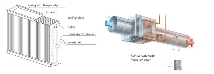
147
148 dimensions The available nominal dimensions of the interposed coolers / heaters are standardised according to EN 1505 and can be selected as indicated in the table of standard dimensions shown in this Manual in section A They refer to the length, with a tolerance of +0 to -5 mm. The dimensions depend on the manufacturer, and with regard to the height (H) are usually available in multiples of 30, 40 or 60 mm. The width (W) is usually available in multiples of 50 and/or 100 mm. In order to guarantee that the accessory functions correctly, it is recommended that the ratio (W/H) should be 4, and that there should be an even supply of air inflow. inspection possibilities HIt must be possible at all times to inspect interposed coolers and/or heaters for leakage, contamination etc. For this purpose, an inspection hatch must be incorporated in the air ducts, immediately before and after the cooler and/or heater. (see L ) installation instructions Interposed coolers and heaters must be installed in accordance with the manufacturer s instructions. For the installation of the coolers / heaters between the air ducts, see also the section installation instructions for accessories. In contrast to the stipulations of that section, a suspension structure must be made at a distance of mm both before and after the cooler / heater. (see L )
, seams and suchlike must be finished in such a way that the fibre material cannot be carried along through the air flow.")
149 fitting and finishing of insulation The insulation must be fitted in accordance with the manufacturer s / supplier s instructions. Specifically in the case of fibrous material (internal insulation), seams and suchlike must be finished in such a way that the fibre material cannot be carried along through the air flow. In order to prevent condensation, the insulation for coolers must be provided with a vapour-tight finish on the outside, if condensation can occur. condensate drainage Coolers must have a drip trap and drain pan, with a provision for condensate drainage with inclusion of a siphon and sufficient height to compensate for the pressure difference that occurs. The drainage pipe must also have a non-pressure drainage provision. transport and storage A great deal of attention must be given to the transport. Coolers and heaters must be transported in a responsible and emphatically careful manner, in such a way that transit damage is prevented. It is therefore recommended that wooden crates or containers should be used for their transport. Coolers / heaters are liable to distortion if handled carelessly or roughly. It is therefore essential to unload them with great care. Damage to cooling pipes increases the likelihood of leakage. To prevent damage as much as possible, it is recommended that the timing of the delivery to the construction site should be closely co-ordinated with the progress of the installation.
150 L humidifiers general The steam humidifiers that are used shall be of either direct-steam or indirect-steam type. The distribution manifold must be installed at an inclined angle or vertically upright, in accordance with the manufacturer s instructions. For the correct condensate drainage, the pressure in the return pipe must be considerably lower than the prevailing steam pressure. material quality For normal comfort ventilation, humidifiers are made from the following materials: casing: usually made of coated Sendzimir galvanised sheet steel with a drain pan. In special cases, the casing shall be made of stainless steel. distribution manifold: stainless steel. joints Humidifiers must have a casing with a flanged edge, so that this can be securely joined with the air duct system. If reducing couplings are needed for this, see the section air ducts for the types of these. For optimum functioning of the humidifier, see installation instructions below..
151 dimensions Humidifiers can usually be adapted to the existing dimensions. It is recommended that the supplier should be consulted about the possible in-build lengths of distribution manifolds. inspection possibilities It must be possible at all times to inspect a humidifier with regard to leakage, contamination etc.. For this purpose, the humidifier must be sufficiently removable to allow all components of the humidifier to be inspected and if necessary changed. installation instructions Humidifiers must be installed in accordance with the manufacturer s instructions. For the installation of humidifiers between the air ducts, see also the section installation instructions for accessories. The humidifiers must be fitted in such a way that they form a rigid and stable whole with the air ducts. It must be possible to install the waterside connections with electric power off. To ensure that the steam is well absorbed in the air, a 2 m length of straight duct must be installed after the humidifier. Humidifiers are liable to distortion if handled carelessly or roughly. It is therefore essential to unload them with great care. To prevent damage as much as possible, it is recommended that the timing of the delivery to the construction site should be closely co-ordinated with the progress of the installation. fitting and finishing of insulation The insulation must be fitted in accordance with the manufacturer s / supplier s instructions. Specifically in the case of fibrous material (internal insulation), seams and suchlike must be finished in such a way that the fibre material cannot be carried along through the air flow. In order to prevent condensation, the insulation for adiabatic humidifiers must be provided with a vapour-tight finish on the outside.
152 condensate drainage The humidifiers must have a drain pan, with a provision for condensate drainage with inclusion of a siphon and sufficient height to compensate for the pressure difference that occurs. The drainage pipe must also have a non-pressure drainage provision. transport and storage A great deal of attention must be given to the transport. Humidifiers must be transported in a responsible and emphatically careful manner, in such a way that transit damage is prevented. It is therefore recommended that wooden crates or containers should be used for their transport. Steam humidifiers are liable to distortion if handled carelessly or roughly. It is therefore essential to unload them with great care. Damage to cooling pipes increases the likelihood of leakage. L filter sections material quality For normal comfort ventilation, filter sections are made from the following materials: casing: Sendzimir galvanised sheet steel, provided with an inspection hatch or door.


153 Other material, depending on the application, in consultation with the supplier. joints The filter section must have a casing and a flanged edge, so that this can be securely joined with the air duct system. If reducing couplings are needed for this, see the section air ducts for the types of these. dimensions The nominal dimensions of the filter section refer to the standard dimensions of the filter units with a tolerance of +0 to -5 mm. The dimensions are standardised as shown in the table below. The length of the filter varies according to the type and construction, from 200 mm to 915 mm.
154 installation instructions For the installation of filter sections, see the section installation instructions for accessories. inspection possibilities It must be possible at all times to inspect the filter section with regard to contamination. For this purpose, there must be, in the installed situation, a possibility to easily remove, check and replace the filter. The degree of contamination can be measured using a Delta P (differential pressure) meter. fitting and finishing of insulation The insulation must be fitted in accordance with the manufacturer s / supplier s instructions. Specifically in the case of fibrous material (internal insulation), seams and suchlike must be finished in such a way that the fibre material cannot be carried along through the air flow.
155 L inspection hatches general Although the Luka installation instructions recommend the installation of hatches to provide possibilities for inspection, these should only be fitted if they are stated or indicated in the specifications or contract drawings. Where the specifications state that the air duct systems must be provided with inspection hatches, the positions and dimensions of these must be indicated on the drawing. These hatches, provided with a gasket, must be securely fastened to the duct section, without weakening the structural execution of this section. The duct section can also be made as a complete formed component, provided with a hatch. This duct section can be installed between the sections of the ongoing main duct. material quality For normal comfort ventilation, inspection hatches must be made of the same materials as the air ducts. An exception to this are the mineral wool and rigid foam ducts, for which metal hatches can be used. dimensions The dimensions depend on the manufacturer and can, for example, be selected as indicated in the following table for standard dimensions: The nominal dimensions of the inspection hatches have a tolerance of +0 to -5 mm..
, seams and suchlike must be finished in such a way that the fibre material cannot be carried along through the air flow.")
156 fitting and finishing of insulation The insulation must be fitted in accordance with the manufacturer s / supplier s instructions. Specifically in the case of fibrous material (internal insulation), seams and suchlike must be finished in such a way that the fibre material cannot be carried along through the air flow. installation Non-insulated inspection covers can be in-built or on-built in both round tube and rectangular duct. After carefully making the correct opening in the duct, the inspection cover must be installed in accordance with the manufacturer s instructions. Insulated inspection covers are normally installed in the case of insulated ducts. After carefully making the correct opening in the duct, a sealant must first be applied on the underside of the inspection cover frame, before installing this on the opening that has been made. The frame should preferably be fastened to the sheet steel duct wall using pop rivets or self-tapping screws. The insulation on the inspection cover frame must then be finished using aluminium tape.


157 L measurement stations to be in-built in ducts material quality For normal comfort ventilation, measurement stations are made from the following material: casing: Sendzimir galvanised steel or plastic PPS..


158 joints Rectangular measurement stations must have a casing with a flanged edge, so that this can be securely joined with the air duct system. If reducing couplings are needed for this, see the section air ducts for the types of these. Round measurement stations can have either a flanged edge or a push-in joint. dimensions The dimensions are standardised according to EN 1505 and 1506 and can be selected as indicated in the table of standard dimensions shown in this Manual in sections A1.06 and A The nominal dimensions of the measurement stations have a tolerance of +0 to -5 mm. fitting and finishing of insulation The insulation must be fitted in accordance with the manufacturer s / supplier s instructions. Specifically in the case of fibrous material (internal insulation), seams and suchlike must be finished in such a way that the fibre material cannot be carried along through the air flow. installation instructions For the installation of measurement stations, see the section installation instructions for accessories. The measurement station must be installed in such a way that the arrow on the casing points in the direction of the air flow. This is very important for correct functioning.
159 L round and rectangular sound attenuators L round sound attenuators Material quality For manufacturing round sound attenuators, the following materials are used: Sendzimir galvanised tube for the outer jacket and perforated Sendzimir galvanised tube for the inner jacket (rigid attenuators); aluminium spiral-wound flexible tube (semi-flexible attenuators); plastic, polystyrene foam rubber (sound attenuator in duct). wall thickness For the Sendzimir galvanised tube, the standard implementation must have a wall thickness as shown below. For the (semi-)flexible attenuator, the wall thickness depends on the manufacturer. types of sound attenuators Round attenuators appear in general as: The generally available types of round sound attenuators are: rigid attenuators (both straight and in the form of a bend) Rigid attenuators consist
160 of a spiral-wound (or rolled sheet with longitudinal seam) outer jacket and a perforated inner jacket with acoustic insulation material between these two jackets, in the form of rock wool or glass wool. Between the insulation and the perforated inner jacket, there is a cloth to prevent the fibres of the insulation material from entering the duct. The ends of the attenuator have a push-in joint, possibly including a rubber sealing ring or with flanges, so that the attenuator can be securely joined with the air duct system. Depending on the application for which the attenuator is used, it can be provided with a coulisse or core. semi-flexible attenuators Semi-flexible attenuators consist of an inner and outer hose made of flexible aluminium hose, with glass wool insulation between them. Between the inner hose and the insulation, there can optionally be a cloth to prevent the fibres of the insulation material from entering the duct. The inner hose is perforated. The ends have a push-in joint for direct installation in the air duct system. length of sound attenuators The length of a sound attenuator depends on its function in the air duct system. The most frequently used attenuators are available in lengths of 300, 500, 600, 750, 900, 1000 and 1200 mm. diameters Diameters of sound attenuators are standardised according to EN 1506 and can be selected as indicated in the table of standard dimensions shown in this Manual in section A The thickness of the insulation depends on the use, and is available in 25, 50 and 100 mm.
, seams and suchlike must be finished in such a way that the fibre material cannot be carried along through the air flow.")
161 fitting and finishing of insulation The insulation must be fitted in accordance with the manufacturer s / supplier s instructions. Specifically in the case of fibrous material (internal insulation), seams and suchlike must be finished in such a way that the fibre material cannot be carried along through the air flow. bends of semi-flexible sound attenuators A minimum bend radius causes a large pressure drop, so an attempt must be made to use the largest possible bend radius. For semi-flexible attenuators, a minimum bend radius of R= d + 2 x the insulation thickness must be used. The suppliers advise a minimum bend radius of 2 x the diameter (d). Double bends must be avoided. installation instructions For the installation of round sound attenuators, see the section installation instructions for accessories.

162 L rectangular sound attenuators "guso ring" material quality For manufacturing rectangular sound attenuators, the following materials are used: outer jacket: Sendzimir galvanised sheet; coulisses: mineral wool panels, finished to prevent the fibres from entering the air flow. Other material, depending on the application, in consultation with the supplier. joints Rectangular sound attenuators must have a flanged edge, so that this can be securely joined with the air duct system. If reducing couplings are needed for this, see the section air ducts for the types of these. dimensions The dimensions are standardised according to EN 1505 and can be selected as indicated in the table of standard dimensions shown in this Manual in section A1.06. The most frequently used standard lengths are: 500, 750, 1000, 1250, 1500 mm. Other lengths, depending on the application, in consultation with the supplier. The nominal dimensions of the sound attenuators have a tolerance of +0 to -5 mm.
, seams and suchlike must be finished in such a way that the fibre material cannot be carried along through the air flow.")
163 fitting and finishing of insulation The insulation must be fitted in accordance with the manufacturer s / supplier s instructions. Specifically in the case of fibrous material (internal insulation), seams and suchlike must be finished in such a way that the fibre material cannot be carried along through the air flow. inspection possibilities It must be possible at all times to inspect the sound attenuator with regard to contamination etc. For this purpose, there must be an inspection hatch near the sound attenuator. (L ) installation instructions For the installation of rectangular sound attenuators, see the section installation instructions for accessories. airtightness Because a sound attenuator is regarded as an air duct, the same airtightness requirements are applicable as for all air ducts.
164 L flexible hoses For the correct installation of flexible hoses, the following points for attention must be observed. points for attention A brief outline is given of: general; shortening hoses; making connections; suspension points; brackets; bends; connection to ducts and fittings; static electricity. general fully extend the hose: if the hose is not fully extended, this results in unnecessary loss of pressure; never use more hose than is absolutely necessary, unless the calculation has taken this into account; an attempt should be made to use minimum 0.5 m to maximum 1.5 m of hose. If a greater length must be used, the hose must be correctly suspended with brackets; when installing the hose, ensure that no damage is caused to the hose; damaged inner hoses must be immediately replaced; minor damage to the outer jacket must be finished with tape (aluminium tape or PVC tape, depending on the material of the hose).
165 shortening non-insulated hoses fully extend the hose; measure the required length and mark this point with a felt pen; cut the material around the entire circumference between the spiral-winding; use wire-cutters to cut through the spiral of the hose; cut off the superfluous spiral. shortening insulated hoses fully extend the hose;; measure the required length and mark this point with a felt pen; using a sharp knife, cut through the outer jacket, the insulation material and the inner hose; cut the hose around the entire circumference and use wire-cutters to cut through the spiral of the inner hose. Cut off the superfluous spiral; trim off any superfluous insulation material using scissors. making connections with non-insulated hoses shorten the hose in the correct way; push the hose at least 40 mm over the connection; then fix the hose with a strong hose clamp; the hose can also be fitted using a so-called guso ring. However, this must be done in accordance with the suppliers installation instructions.
166 making connections with insulated hoses shorten the hose in the correct way; push the insulation material and the outer jacket back a little, and stick the outer jacket, including the insulation material, firmly and in an airtight manner to the inner hose, using tape. push the hose at least 40 mm over the connection; preferably use tape with a width of at least 50 mm; using a strong hose clamp, fix the outer jacket and the inner hose to the connection; use aluminium tape for pure aluminium and aluminium foil hoses, and use plastic tape for plastic hoses; the hose can also be fitted using a so-called guso ring. However, this must be done in accordance with the suppliers installation instructions. suspension points the maximum allowable sag of the hose between two fastening points is 50 mm (measured in the centre); the distance between two suspension points can vary from 1.5 to 3 m. This distance depends on the type of hose that is used. brackets A hose is generally very flexible and can become distorted quite easily. Distortion reduces the internal diameter and increases the pressure loss. When fitting brackets (using e.g. perforated strapping), it is therefore important to ensure that the diameter
167 of the hose is not reduced. The hose must also be supported over at least half the circumference. bends of flexible hoses According to EN 13180, the bend radius of a flexible duct must comply with R = d. However, this minimum bend radius causes a large pressure drop, so an attempt must be made to use the largest possible bend radius. For flexible hoses, a minimum bend radius of R = d + 2 x the insulation thickness should be used. The manufacturers advise a minimum bend radius of 2 x the diameter (d). Double bends must be avoided.
168 connection to ducts and fittings The connection of flexible hoses to ducts and fittings must be executed with due care. Because many hoses are installed in a bend immediately after the connection to the duct or fitting, it is necessary to use a supporting bracket. If the duct connection is too sharp, flexible hoses can become split. When connecting a hose to light or air fittings, the connection must be made as direct as possible, while taking account of the above remarks. Too many bends in the hose near a fitting cause the pressure loss to increase unnecessarily, and can cause noise. A minimum bend radius gives a large pressure drop. An attempt must therefore be made to use the largest possible bend radius with a straight intake of 2 x the diameter (d). For flexible hoses, a minimum bend radius of R = d + 2 x the insulation thickness should be used. The suppliers advise a minimum bend radius of 2 x the diameter (d). Double bends must be avoided.
169

170 static electricity In a number of situations, especially in the case of plastic hoses, it is possible that the build-up and discharge of static electricity can cause an explosion hazard. By connecting the spiral wire of the flexible hose to an earth wire, the build-up of static electricity can be minimised.
171 L plenum boxes (grille plenums) material quality Plenum boxes for grilles can be made from metal, mineral wool, plastic or rigid foam. Plenum boxes can be provided with internal or external insulation, depending on what is required. wall thickness Wall thickness of the material depends on the application and type of material. types There are many types of plenum boxes, depending on the use, type of grille and application. A plenum box for e.g. a ceiling grille will normally look like the figure below. A distinction can be made between a plenum box with a top connection and a side connection for a duct system. The seams in the plenum box must be made airtight by applying permanently plastic sealant. connection to ducts Ducts are usually connected to the plenum box using a flexible hose. For this purpose, a flat saddle piece is fitted to the box. For this, see the installation instructions for flexible hoses.
172 installation of grille plenums There are various possibilities for installing grille plenums in e.g. a dropped ceiling, but this depends on the manufacturer and type. In any case, however, the grille plenums must have installation provisions for fastening the box (using e.g. adjustable hangers) to the structural ceiling above.

173 M.1.00 Airtightness M.1.01 general Working closely with suppliers and manufacturers of accessories, Luka aims to restrict the air leakage of the air flow path, and thus to reduce the energy use of the air-conditioning installation. The air flow path should be understood to mean: air ducts; accessories to be interposed between air ducts; flexible hoses. M.1.02 airtightness of air ducts An air duct system is only required to be perfectly airtight in exceptional cases. For example, a leak may be impermissible for safety reasons, e.g. if the duct carries hazardous gases or heavily polluted air. A duct system for a ventilation and climate control installation, which is made according to current production methods, will have a certain amount of leakage at seams and joints. For reasons of finance and operational disruption, it is desirable to establish the allowable amount of leakage air. Although the leakage occurs at the transverse and longitudinal joints, especially at the corners, it is assumed that the amount of leakage air is proportional to the surface area of the duct wall. Research has shown that the amount of leakage air per m2 of wall surface area can be calculated as follows:

174 The permissible amount of leakage air is related to classes of airtightness, for which a certain test pressure applies, derived from EN 1507 and In international practice, the following classes are used: Unless otherwise specified, Luka uses Class C as the airtightness requirement. Measurements can determine whether the section of duct being tested satisfies the requirement. In practice, after measurement with the appropriate test equipment, the degree of leakage is immediately assessed on the basis of a graph that shows the maximum allowable air loss for Class C airtightness for installed duct sections. When the leakage test is performed, it shall comply with the following points: the section to be tested has been installed, but preferably not yet provided with external insulation;

175 the section to be tested has been separated in an airtight manner from the rest of the system, together with any accessories interposed within that section, for which the test requirements have been established; if a total duct system, also known as the air flow path, is being assessed, the section to be tested must have a surface area of minimum 10 m2 and maximum 80 m2; (depending on the capacity of the test equipment) the section to be tested must be kept at the test pressure for 5 minutes before the leakage volume flow is measured; a maximum of 1% of the total surface area of the duct project must be tested; the deviation of the test pressure is permitted to be approx. 20 Pa. operating principle The leakage tester basically consists of an adjustable-speed fan, a manometer to measure the pressure in the air duct, a calibrated air intake (venturi) and a precision inclined manometer to measure the suction pressure in the venturi. Three different air intakes are supplied (each with its own curve) in order to cover the entire range of the leakage tester. When the leakage tester is connected to the duct section to be tested, the speed of the fan is adjusted so that the required test pressure is maintained within the established margin. The amount of air lost through leakage is sucked through the venturi of the leakage tester. From the reading shown by the inclined manometer, the air leakage in l/s can be read off the table on the leakage tester. The measuring instrument must be calibrated every 3 years, and must have a measurement accuracy of ±5 %.
176 In addition to the leakage tester described above, a version is also available that gives a digital reading. As a result of the long-term accuracy, calibration can take place every 5 years. The above procedures are laid down in EN 1751, 1507 and
177 M.1.03 airtightness of accessories M measurement method for air leakage of accessories In order to assess whether an accessory complies with the stated airtightness requirement, measurements must be made. The operating principle of the measurement is basically the same as for measuring air ducts. For the measurements on a single accessory, a standard test fixture is required. A measurement fixture of this kind, in accordance with EN 1751, is shown in the photograph on the left of the text. For the Luka System Certificate, Luka members must obtain measurement reports from accessory suppliers or information via the Luka Accessory Register, the LAR, in order to assess whether the projected accessories comply with the stated airtightness requirement. Measurements must be performed by a measurement institute with a quality system that conforms to ISO The (inter)national accreditation body of this measurement institute must be recognised and a member of the EA MLA. With regard to the recognition, see the website of the Dutch Accreditation Council (Raad van Accreditatie: The Luka members also accept the measurement reports of accessory suppliers themselves, provided that these suppliers have a valid TÜV Rheinland Nederland BV Meetlabel (measurement label).
178 M rectangular accessories The European standard EN 1751 provides that, for determining the allowable air leakage of damper registers, when the actual length is 1 metre, an equivalent length of 1 metre should be used for the length of these accessories. For practical reasons, it has been agreed between Luka and suppliers or manufacturers that this equivalent length should be used for all rectangular accessories, insofar as the technical execution permits and the actual length is < 1 metre. This entails that the formula for the maximum air leakage for each rectangular accessory is: øl/acc = f.ps0.65.(2h + 2W).L (l/s)
179 where: øl/app = maximum amount of air leakage in l/s f = leakage factor Ps = static pressure Pa B = width of the component in metres H = height of the component in metres L = length of the component in metres; L = 1 when the length of the accessory is less than 1 metre, or L = the actual length if the length is more than 1 metre. example: calculation of the allowable air loss For a fire damper 600 x 600 mm with L = 500 mm. Ps = 1000 Pa f = (see table in section M.1.02 airtightness of air ducts ). This fire damper is thus permitted to leak a maximum of 1.92 l/s to the surroundings at 1000 Pa in order to comply with Airtightness Class B. On the basis of the above formula, the maximum allowable leakage for an accessory (with a length < 1 metre) in Airtightness Class B at the following pressures can be calculated as follows:

180 M round accessories For practical reasons, Luka has agreed with suppliers or manufacturers that the equivalent length of 1 metre, as stipulated in the standard EN 1751, should also be used for all round accessories, insofar as the technical execution permits and the actual length of the accessory is < 1 metre. This entails that the formula for the maximum amount of air leakage for each round accessory that complies with Airtightness Class C is: M flexible hoses The procedure for determining the airtightness of flexible hoses is laid down in EN M determination of surface area of the duct to be tested The table below shows how to determine the number of m2 of system surface area that must be used in the formula for the air leakage. In the table, a length of 1000 mm is used for the accessory, unless the actual length is greater than 1 metre. In that case, the actual length must be filled in. (see also section 5.02 measurement methods )
SECTION HVAC DUCTS AND CASINGS
 SECTION 23 31 00 HVAC DUCTS AND CASINGS PART 1 -GENERAL 1.1 SUMMARY A. Section includes metal ductwork, nonmetallic ductwork, casing and plenums, buried ductwork, kitchen hood ductwork, duct cleaning.
SPECIFICATION FOR REINFORCED SOIL WALL
 SPECIFICATION FOR REINFORCED SOIL WALL 1.0 EXTENT OF WORK The work shall consist of Reinforced Soil walls built in accordance with this specification and in conformity with the lines, levels and details
Construction. Tricosal Waterstops - Tricomer. Waterstops for joint sealing in watertight concrete construction according to DIN and DIN
 Construction Product Data Sheet Edition 19 April 2013 Tricosal Waterstops - Tricomer Waterstops for joint sealing in watertight concrete construction according to DIN 18541 and DIN 18541-2 Product Description
SECTION METAL DUCTS
 SECTION 15815 METAL DUCTS PART 1 - GENERAL 1.1 RELATED DOCUMENTS A. Drawings and general provisions of the Contract, including General and Supplementary Conditions and Division 1 Specification Sections,
11/2 HOUR UL CLASSIFIED CURTAIN TYPE (D)IBD2, (D)IBD2SS AND IBDT FIRE DAMPERS
IBD2, (D)IBD2SS AND IBDT FIRE DAMPERS") 3900 Dr. Greaves Rd. Kansas City, MO 64030 (816) 761-7476 FAX (816) 765-8955 INSTALLATION INSTRUCTIONS 11/2 HOUR UL CLASSIFIED CURTAIN TYPE (D)IBD2, (D)IBD2SS AND IBDT FIRE DAMPERS APPLICATION The fire
3900 Dr. Greaves Rd. Kansas City, MO 64030 (816) 761-7476 FAX (816) 765-8955 INSTALLATION INSTRUCTIONS 11/2 HOUR UL CLASSIFIED CURTAIN TYPE (D)IBD2, (D)IBD2SS AND IBDT FIRE DAMPERS APPLICATION The fire
84 Lapping & Jointing 86 Service Pipe Penetrations 87 Sealing to Cavity Wall Constructions 88 Protecting Membranes System Components.
 84 Lapping & Jointing 86 Service Pipe Penetrations 87 Sealing to Cavity Wall Constructions 88 Protecting Membranes 90 System Components installation/ SYSTEM COMPONENTS INSTALLATION ADVICE LAPPING and JOINTING
Sandwich panel SPA Product description
 Sandwich panel SPA Product description Ruukki offers a sandwich panel system that combines an attractive appearance with excellent thermal insulation and fire-resistance. The panels are of a lightweight,
a gray co. SPIRAL, OVAL & RECTANGULAR DUCT CATALOG Lake Park, GA Coats, NC
 a gray co. SPIRAL, OVAL & RECTANGULAR DUCT CATALOG Coats, NC Lake Park, GA Product Return Policy POLICIES All spiral, oval and rectangular duct products are made to order. Items cannot be cancelled once
SECTION IMPACT RESISTANT WALL PROTECTION
 SECTION 10265 PART I - GENERAL 1.01 DESCRIPTION A. Scope: Work under this Section shall include all materials and installation necessary to provide Impact-Resistant Wall Protection including Wall guards,
PRODUCT DATA SHEET. SikaFuko Eco-1 PRODUCT- DESCRIPTION. Re-injectable hose for sealing construction joints in watertight structures
 PRODUCT DATA SHEET SikaFuko Eco-1 Re-injectable hose for sealing construction joints in watertight structures PRODUCT- DESCRIPTION USES PRODUCT CHARACTERISTICS TESTING & APPROVALS Re-injectable hose system
INDIA HABITAT CENTRE New Delhi
 INDIA HABITAT CENTRE New Delhi Tender For Renovation of Exhaust Air Ducting Works in Basements Date: January, 2014 Prepared by Sterling India Consulting Engineers New Delhi, India TABLE OF CONTENTS S.No.
PREFA Aluminiumprodukte GmbH Page 1 of 25
 Tender Specifications 120901 PREFALZ Double Standing Seam_2012 ---------------------------------------------------------------------------------- 01. Text GENERAL PRELIMINARY REMARKS Roof ----------------------------------------------------------------------------------
Division 11 - Equipment Section 11401
 PART 1 - GENERAL 1.1 GENERAL A. Division 1 General Requirements applies and becomes a part of this Section of the Specification as fully as if repeated herein. B. Items of equipment which are included
B. Polyethylene samples shall be submitted for Owner approval of color and quality.
 Glass Rail ENGINEERED DASHERBOARD SPECIFICATIONS PART 1 - GENERAL 1.01 PROJECT SCOPE A. Contractor shall furnish and install one complete set of steel framed dasherboards as indicated on the drawings and
SECTION ALUMINUM GATES
 P.O. Box 1058 370 South Athol Rd. Athol, Massachusetts 01331 Phone: (978) 249-7924 Fax: (978) 249-3072 SECTION ALUMINUM GATES PART 1 GENERAL 1.01 SCOPE OF WORK A. The CONTRACTOR shall furnish all labor,
Channel Drain Shower Base. Aqua Line pro. Installation Instructions
 Channel Drain Shower Base. Aqua Line pro Installation Instructions 02 JACKOBOARD Aqua Line pro System components a JACKOBOARD Aqua Line pro b JACKOBOARD Aqua Line pro - Horizontal Drain (Art. No. 4510370)
RAISED ACCESS FLOOR SYSTEM TECHNICAL SPECIFICATION
 RAISED ACCESS FLOOR SYSTEM TECHNICAL SPECIFICATION PROVISIONAL BILL OF QUANTITIES RAISED ACCESS FLOOR SYSTEM TECHNICAL SPECIFICATION 1 RAISED ACCESS FLOOR SPECIFICATION SYSTEM DESCRIPTION This specification
PASSAIC COUNTY TECHNICAL INSTITUTE CCA 1422 NEW S.T.E.M. BUILDING 2017
 SECTION 10505 - METAL STUDENT LOCKERS PART 1 - GENERAL 1.01 SCOPE OF WORK A. Drawings and general provisions of the Contract, including General and Supplementary Conditions and Division 1 Specification
SECTION HANGERS AND SUPPORTS FOR ELECTRICAL SYSTEMS
 SECTION 26 05 29 HANGERS AND SUPPORTS FOR ELECTRICAL SYSTEMS PART 1 GENERAL 1.1 DESCRIPTION A. Scope: 1. CONTRACTOR shall provide all labor, materials, equipment, and incidentals as shown, specified, and
Northpointe Renovation EPN #1701 F/A Project #17027 September 8, 2017
 SECTION 055213 - PIPE AND TUBE RAILINGS PART 1 - GENERAL 1.1 RELATED DOCUMENTS A. Drawings and general provisions of the Contract, including General and Supplementary Conditions and Division 01 Specification
L'ISOLANTE K-FLEX. LNG applications Manual
 L'ISOLANTE K-FLEX LNG applications Manual LNG applications Manual The insulation LNG plants may forsee a multilayer design according to the specific characteristics and the working temperatures of the
Construction. Injectable hose for sealing construction joints in watertight structures. Product Description. Product Data. Tests.
 System Product Data Sheet Edition 09/01/2009 Identification no: 02 07 03 07 010 2 000099 ( SikaFuko Eco 1 Injectable hose for sealing construction joints in watertight structures Construction Product Description
Construction. Hydrophilic, swellable hose for sealing construction joints in watertight structures. (formerly Sika Injectoflex HPM)
") System Product Data Sheet Edition 06/12/2010 Identification no: 02 07 03 07 010 2 000099 (formerly Sika Injectoflex HPM) SikaFuko Swell 1 (formerly Sika Injectoflex HPM) Hydrophilic, swellable hose for
System Product Data Sheet Edition 06/12/2010 Identification no: 02 07 03 07 010 2 000099 (formerly Sika Injectoflex HPM) SikaFuko Swell 1 (formerly Sika Injectoflex HPM) Hydrophilic, swellable hose for
SECTION ACOUSTICAL PANEL CEILINGS
 SECTION 095113 ACOUSTICAL PANEL CEILINGS PART 1 - GENERAL 1.1 RELATED DOCUMENTS A. Drawings and General Provisions of the Contract, including General and Supplementary Conditions and Division 01 Specification
FOLLOW US ON PLEXIGLAS UNDERWATER WINDOWS UNDERWATER WINDOWS. Experience and Enjoy Quality
 FOLLOW US ON PLEXIGLAS Experience and Enjoy Quality WWW.UNDERWATERWINDOWS.EU Presentation of Material PLEXIGLAS is the world s first acryl ic (= polymethyl methacrylate, PMMA). lt has also been used for
FIRE PROTECTION. GTEC Shaftwall systems 244 GTEC Shaftwall Stairwell systems 248 GTEC Horizontal Shaftwall systems 249 GTEC Encasement systems 250
 FIRE PROTECTION GTEC Shaftwall range uses a specially designed system to protect voids and shafts in buildings. It resists pressure changes and enables installation from one side of the shaft only. GTEC
TECHNICAL SPECIFICATION DANTECO HERMANNS. CONTAINER FOR BULK POWDER Equipped with HERMANNS Aeration and Conveyance Device
 TECHNICAL SPECIFICATION DANTECO HERMANNS CONTAINER FOR BULK POWDER Equipped with HERMANNS Aeration and Conveyance Device 6058(20') x 2438(8') x 2591(8'6") MODEL NO. : CX09-20SNX1 SPEC. NO : CX09-20SNX1-S3
Installation instruction
 Installation instruction Ci51 www.contura.eu 114 CERTIFICATE Declaration of performance according to Regulation (EU) 305/2011 No. Ci51-CPR-150821-SE-2 PRODUCT Product type Type designation Manufacturing
Cold Work Cladding Fabrication & Application
 TRADE OF Industrial Insulation PHASE 2 Module 3 Substructures, Advanced Cold Work and Cladding UNIT: 4 Cold Work Cladding Fabrication & Application Produced by In cooperation with subject matter expert:
Fire Barrier Duct Wrap 615+
 Fire Barrier Duct Wrap 615+ Duct Wrap Fire Protection System for Commercial Kitchen Grease and Ventilation Air Ducts Product Data Batts and blankets for use in fire resistive duct assemblies see UL fire
INDUSTRIALIZED CONSTRUCTION BRASILIT FIBER CEMENT BOARD, PANELS AND ACCESSORIES FOR THE EXECUTION OF YOUR CONSTRUCTION
 INDUSTRIALIZED CONSTRUCTION BRASILIT FIBER CEMENT BOARD, PANELS AND ACCESSORIES FOR THE EXECUTION OF YOUR CONSTRUCTION Make it Easier with Brasilit BRASILIT FIBER CEMENT BOARDS AND PANELS. QUICKNESS AND
HOT ROLLED STEEL FLAT PRODUCTS FOR STRUCTURAL FORMING AND FLANGING PURPOSES SPECIFICATION (Third Revision of IS 5986)
") For Comments Only Draft Indian Standard Doc: MTD 4(4939) HOT ROLLED STEEL FLAT PRODUCTS FOR STRUCTURAL FORMING AND FLANGING PURPOSES SPECIFICATION (Third Revision of IS 5986) ICS 77.140.50 Not to be reproduced
For Comments Only Draft Indian Standard Doc: MTD 4(4939) HOT ROLLED STEEL FLAT PRODUCTS FOR STRUCTURAL FORMING AND FLANGING PURPOSES SPECIFICATION (Third Revision of IS 5986) ICS 77.140.50 Not to be reproduced
FC /2 Hour Curtain Fire Dampers
 FC-2000 1-1/2 Hour Curtain Fire Dampers Installation Instructions 44-3521- 0, Rev. B Part No. 44-3521-0, Rev. B Issued March 2016 Applications Johnson Controls provides a 1-1/2 hour curtain fire damper
Installation instructions
 Installation instructions Holetherm Double-walled flue gas discharge system (DW) 2016 All information in this release is subject to misprints. No liability is accepted for the consequences of misprints.
SECTION RESILIENT SHEET FLOORING
 SECTION 09 65 16 RESILIENT SHEET FLOORING SPEC WRITER NOTE: Delete text between // // not applicable to project. Edit remaining text to suit project. PART 1 - GENERAL 1.1 SUMMARY A. Section Includes: 1.
Cold Rooms Kide
 COLD ROOMS Cold Rooms 2 Cold under control KIDE it is a business Group manufacturer of cold-rooms, insulation panels, insulated doors, refrigeration units and drying units, offering integral solutions
BEARING METAL STUD FRAMING
 L-1 Section 05410 Long Form Specification LOAD BEARING METAL STUD FRAMING This section includes axially loaded steel studs, with unique slotted top channels, usually of 0.91, 1.2 and 1.5 mm (16, 18, or
MANUFACTURING TOLERANCES FOR PROFILED METAL ROOF AND WALL CLADDING
 CI/SfB (4-) Rh2 MAY 2006 MANUFACTURING TOLERANCES FOR PROFILED METAL ROOF AND WALL CLADDING Contents Page 1.0 General 1 2.0 Methods for measuring tolerances 2 2.1 Sheet length 2 2.2 Sheet cover width,
SECTION PLATE CONNECTED WOOD TRUSSES
 SECTION 06173 PLATE CONNECTED WOOD TRUSSES PART 1 GENERAL 1.01 SUMMARY A. Section Includes: 1. Shop fabricated wood trusses for roof and floor framing. 2. Bridging, bracing, and anchorage. B. Related Sections:
SP Standard Profile. Flanged to Duct Install Type THERMAL BREAKS OPPOSED ACTION PARALLEL ACTION. T.A. Morrison & Co. Inc.
 1 SUBMITTAL DATA Series 9000 BF Thermally Insulated Damper with Thermally Broken Frames & Blades SP Standard Profile Flanged to Duct Install Type THERMAL BREAKS OPPOSED frame is 4 (101.6 mm) deep x 1 (25.4
Design & Construction Standards, Revised January
 PART 1: GENERAL 1.01 Purpose: A. This standard is intended to provide useful information to the Professional Service Provider (PSP) to establish a basis of design. The responsibility of the engineer is
Construction. Injectable Hose for Sealing Construction Joints in Watertight Structures. Product Description. Tests. Product Data
 Construction System Product Data Sheet Edition: 03/09/2013 Identification no: 02 07 03 07 010 2 000099 Version: GCC Injectable Hose for Sealing Construction Joints in Watertight Structures Product Description
FireMaster FastWrap XL
 Datasheet Code US: 7--6 MSDS Code US: 06 009 Morgan Thermal Ceramics, a business within the Morgan Ceramics Division of The Morgan Crucible Company plc Grease Duct Enclosure System Air Ventilation Duct
SECTION MASONRY ACCESSORIES
 PART 1 GENERAL 1.01 SCOPE OF WORK A. Contractor shall furnish all labor, materials, equipment and incidentals required to provide masonry accessories as shown on the Contract Drawings and specified herein.
SECTION REINFORCING STEEL
 SECTION REINFORCING STEEL 1. DESCRIPTION This specification shall govern the furnishing and placing of reinforcing steel, deformed and smooth, of the size and quantity designated on the plans and in accordance
Construction. S-Vap 5000E SA Self-adhesive Vapour Barrier. Product Description
 Roofing Product Data Sheet Edition 11.2014 / xtra UK Identification no. 02 09 45 05 100 0 000019 Version no. 03 S-Vap 5000E SA Self-adhesive Vapour Barrier Product Description S-Vap 5000E SA is a multi-layer
CONTRACT NUMBER: W912DQ-08-C % CORRECTED DESIGN 28 JULY 2008
 SECTION 092900 - GYPSUM BOARD 1.1 SUMMARY A. This Section includes the following: 1. Interior gypsum board. 2. Tile backing panels. B. Related Sections include the following: 1. Division 06 Section "Rough
PIPEWORK INSULATION. 14/ Page 1 of 10 Pipework Insulation Rev D
 PIPEWORK INSULATION 14/10-2014 Page 1 of 10 Pipework Insulation Rev D Contents INTRODUCTION General Scope Surfaces to be Insulated Pumps, Turbines etc Performance Minimum Pipe Insulation Thickness Physical
Product Data Sheet SikaFuko Swell-1 Positioning Description Uses Advantages Approval / Standards Construction Product Data Packaging
 Product Data Sheet Version Nos.: 0414 SikaFuko Swell-1 Hydrophilic, swellable hose for sealing construction joints in watertight structures Construction Positioning Description Uses Swellable and injectable
PASSIVE FIRE PROTECTION PRODUCTS
 OCTOBER 2016 PASSIVE FIRE PROTECTION PRODUCTS www.allproof.com CONTENTS FIRE TESTING 1 ADVANCED INTUMESCENT 2 ALLPROOF INTUMESCENT TECHNOLOGY: 2 LOW PROFILE S 3 CONCRETE SLAB TEST RESULTS: 4 FLOOR WASTE
Staggered stud acoustic partition system
 C0 Partitions Staggered stud acoustic partition system All our systems are covered by SpecSure when using genuine Gyproc and Isover products is a non-loadbearing stud partition incorporating a single framework
Construction. Sarnafil TS Polymeric membrane for roof waterproofing. Product Description
 January, 2009 Sarnafil TS 77-15 Polymeric membrane for roof waterproofing Construction Product Description Uses Characteristics / Advantages Approval / Standards Sarnafil TS 77-15 (thickness 1.5 mm) is
Ramps Vip Aldime WHAT DO VIP ALDIME RAMPS HAVE THAT OTHERS DO NOT?
 Ramps Vip Aldime Vip Vip Aldime, established in 2005, is presently a business project within the field of aluminum. Its professional team proudly bears more than 20 years of experience in this sector.
PREFA Aluminiumprodukte GmbH Page 1 of 21
 Tender Specifications 120901 PREFA Shingles_2012 ---------------------------------------------------------------------------------- 01. Text GENERAL PRELIMINARY REMARKS Roof ----------------------------------------------------------------------------------
Kingspan Day-Lite Klick
 Insulated Panel Envelope Systems Roof Wall Façades Lighting Rooftop PV Coldstore Structural Products Cleanrooms UK & Ireland Kingspan Day-Lite Klick Installation Guide Page 2 Accessories Overview Designation
PSI Anti-Corrosion Tapes
 Pipeline Accessories PSI Anti-Corrosion Tapes General Information Technical Data Requirement Specifications Application Instructions Certificates 1 The Systems PSI anti-corrosion tapes have been specially
R-Group Finland Oy. RTA, RWTL and RWTS Lifting anchors Design instructions
 R-Group Finland Oy RTA, RWTL and RWTS Lifting anchors Design instructions According to Eurocodes, EU Machinery directive 2006/42/EC and VDI/BV-BS 6205 CE Approved 28.12.2016 2 Table of contents 1 DESCRIPTION
Insulating systems used in agricultural and industrial buildings
 Insulating systems used in agricultural and industrial buildings INTRODUCTION Since years, RECTICEL is a leading manufacturer of systems for internal insulation. The EUROTHANE product range has been especially
ACOUSTICAL INSULATION (LAGGING) FOR PIPING AND EQUIPMENT
 FOR PIPING AND EQUIPMENT") ACOUSTICAL INSULATION (LAGGING) FOR PIPING AND EQUIPMENT Specification for Acoustical Insulation (Lagging) for Piping and Equipment 1 of 5 TABLE OF CONTENTS 1.0SCOPE..... 3 2.0REFERENCED PUBLICATIONS...
ACOUSTICAL INSULATION (LAGGING) FOR PIPING AND EQUIPMENT Specification for Acoustical Insulation (Lagging) for Piping and Equipment 1 of 5 TABLE OF CONTENTS 1.0SCOPE..... 3 2.0REFERENCED PUBLICATIONS...
FACADE PROFILES FOR VERSATILE APPLICATIONS 01/16
 FACADE PROFILES FOR VERSATILE APPLICATIONS 01/16 EDGE FORMATION JOINT STRUCTURE CONNECTION STRUCTURE REVEAL FORMATION ROOF AND FACADE VENTILATION CUSTOM SOLUTIONS PRODUCT RANGE According to item number
Industry Standard Terms & Definitions Of The Steel Deck Institute
 Industry Standard Terms & Definitions Of The Steel Deck Institute A specialized set of jargon to describe common terms used by manufacturers and other professionals associated with the usage of Steel Deck
UNIVERSITY SERVICES ANNEX James Madison University Harrisonburg, Virginia State Project Code: Architect s Project Number:
 SECTION 095113 - ACOUSTICAL PANEL CEILINGS PART 1 - GENERAL 1.1 RELATED DOCUMENTS A. Provisions of the Contract and of the Contract Documents apply to this Section. 1.2 DEFINITIONS A. AC: Articulation
Pyroscat Duct Wrap XL
 Datasheet Code US: - 0 Thermal Ceramics is a business of Morgan Advanced Materials * Commonly referred to test method CA Section 00 is CDPH Standard Method for the Testing and Evaluation of Volatile Organic
Roofing. Polymeric sheet for roof waterproofing. Product Description. Tests. Product Data Sheet Edition _1
 Product Data Sheet Edition 2014-09_1 Polymeric sheet for roof waterproofing Product Description (thickness 1.5 mm) is a Polyester reinforced, multi-layer, synthetic roof waterproofing sheet based on premium-quality
FORMDECK. constructions. constructions
 FORMDECK constructions constructions Introduction Formdeck300 (FD300) is a very efficient and durable permanent metal tray formwork, reinforcement and ceiling system used for suspended concrete slab construction.
RB WEIR GATES MODEL GENERAL DESCRIPTION DESIGN CONSTRUCTION
 GENERAL DESCRIPTION The Orbinox model RB Weir Gate is designed for downward opening applications where a more accurate flow control is required. The water flows over the top of the slide permitting a constant
SPECIFICATIONS FOR POLYVINYL COATED UNDERGROUND DUCT SYSTEMS & FUME EXHAUST SYSTEMS
 SPECIFICTIONS FOR POLYVINYL COTED UNDERGROUND DUCT SYSTEMS & FUME EXHUST SYSTEMS MINNEPOLIS, MN 5850 Main Street N.E. Minneapolis, MN 55432 LOCLLY CLL: 763-572-0000 TOLL FREE: 1-800-328-1966 FX: 763-572-1100
VINITEX INSTALLATION PROCEDURES
 VINITEX INSTALLATION PROCEDURES 1 INDex INTRODUCTION PAGE 2 HOT AIR manual WELDING PAGE 6 AUTOMATIC WELDING PAGE 10 WELDING TRANSVERSE JOINTS PAGE 13 T-JOINTS MULTIPLE WELDING SEAMS PAGE 15 PERIMETER
SECTION PRE-ENGINEERED MEMBRANE STRUCTURE
 SECTION 13125 PART 1 - GENERAL 1.1 SUMMARY A. Section includes the design, engineering, fabrication and erection of a frame-supported, tensilemembrane structure complete with entrance and exit doors and
PLATON RUGGED, DIMPLED HIGH-DENSITY POLYETHYLENE (HDPE) MEMBRANE THAT KEEPS FOUNDATIONS AND FLOORING DRY ADVANCED TECHNOLOGY EASY INSTALLATION
 MEMBRANE THAT KEEPS FOUNDATIONS AND FLOORING DRY ADVANCED TECHNOLOGY EASY INSTALLATION") DRAINAGE SOLUTIONS SINCE 1908 PLATON RUGGED, DIMPLED HIGH-DENSITY POLYETHYLENE (HDPE) MEMBRANE THAT KEEPS FOUNDATIONS AND FLOORING DRY ADVANCED TECHNOLOGY EASY INSTALLATION PROVEN PERFORMANCE ARMTEC.COM
DRAINAGE SOLUTIONS SINCE 1908 PLATON RUGGED, DIMPLED HIGH-DENSITY POLYETHYLENE (HDPE) MEMBRANE THAT KEEPS FOUNDATIONS AND FLOORING DRY ADVANCED TECHNOLOGY EASY INSTALLATION PROVEN PERFORMANCE ARMTEC.COM
NOVABRIK MORTARLESS CONCRETE BRICK VENEER SPECIFICATION. MASTERFORMAT SECTION (Mortarless Concrete Brick Veneer)
") NOVABRIK MORTARLESS CONCRETE BRICK VENEER SPECIFICATION MASTERFORMAT SECTION 04818 (Mortarless Concrete Brick Veneer) Spec_USA_En_18102005.doc 12/1/2005 Novabrik Page 2 Section 04818 NOVABRIK MORTARLESS
NOVABRIK MORTARLESS CONCRETE BRICK VENEER SPECIFICATION MASTERFORMAT SECTION 04818 (Mortarless Concrete Brick Veneer) Spec_USA_En_18102005.doc 12/1/2005 Novabrik Page 2 Section 04818 NOVABRIK MORTARLESS
mounting systems applications overview
 mounting systems applications overview catalogue version January 2015 tritec mounting systems: overview of applications i. pitched roof: roof-top 1. Tiles, shingles and corrugated panels 1.1 TRI-STAND
Materials Carbon Steel and Malleable Iron are used in the manufacture of concrete inserts. Stainless Steel and other materials are available.
 Concrete inserts offered in this section are designed to provide a pre-set support point in concrete ceilings, walls, and floors. A range of inserts with varying design loads are available. Materials Carbon
Façade panels riveted on an aluminium supporting structure
 Ventilated façade 1 General These application instructions are specifically intended for the fastening of large-size EURO PANELS OVERSEAS N.V. façade panels as outside wall cladding on a ventilated and
When I started tiling, we didn t do our own shower pans that BATHS
 BATHS Preventing Leaks in Tiled Showers Detail the pan properly before any tile is installed BY TOM MEEHAN Photos by Roe Osborn When I started tiling, we didn t do our own shower pans that job fell to
Façade System Trimoterm FTV INVISIO
 Façade System Trimoterm FTV INVISIO Technical document No. 6/ Version / October 0 CONTENT.0 Technical description of the Facade system with Hidden Fixing - INVISIO []. General []. Panel profile []. Panel
INSTALLATION INSTRUCTIONS FOR WICANDERS HYDROCORK
 INSTALLATION INSTRUCTIONS FOR WICANDERS HYDROCORK GENERAL INFORMATION Hydrocork floors are intended for indoor use only. Please read the following instructions before installation. Hydrocork connection
PITTSBURGH CORNING ASSEMBLY INSTRUCTIONS. KWiK N EZ Rigid Track Silicone System for Thinline Series Glass Block
 Page 1 of 6 PITTSBURGH CORNING KWiK N EZ Rigid Track Silicone System for Thinline Series Glass Block ASSEMBLY INSTRUCTIONS Introduction The KWiK N EZ Rigid Track Silicone System is the easiest way to install
ARCHITECTURAL GUIDE SPECIFICATIONS - DESCRIPTIVE
 ARCHITECTURAL GUIDE SPECIFICATIONS - DESCRIPTIVE MANNINGTON COLORFIELDS SHEET RUBBER FLOORING Section 09 65 16 Sheet rubber Flooring (Thermoset Rubber) Created May 2012 Mannington Mills, Inc. P. O. Box
Floor Insulation Underlayment Section Sound Control Matting
 Floor Insulation Underlayment Section 09618 Sound Control Matting Part I General 1.1 Summary A. Section includes a sound control material for achieving an STC and IIC rating in excess of 50 to meet building
HALFEN HLB LOOP BOX Z-HLB-M50 13-E CONCRETE
 HALFEN HLB LOOP BOX Z-HLB-M50 13-E CONCRETE Translation of the General Certificate of Approval Approval Office: German Institute for Construction Engineering (Deutsches Institut für Bautechnik DIBt) Kolonnenstrasse
Roof Replacement. Notes: T-1 (Title Sheet) Roof Key Plan Russell House Student Union 1400 Greene Street Columbia, South Carolina 29208
 Roof Key Plan Russell House Student Union 1400 Greene Street Columbia, South Carolina 29208") Notes: Drawing Index T-1 Title R-1 Roof Plan - Existing Conditions R-2 Roof Plan - New D-1 Roof Details D-2 Roof Details D-3 Roof Details M-1 Mechanical - Roof Plan M-2 Mechanical - Details Roof Key Plan
Notes: Drawing Index T-1 Title R-1 Roof Plan - Existing Conditions R-2 Roof Plan - New D-1 Roof Details D-2 Roof Details D-3 Roof Details M-1 Mechanical - Roof Plan M-2 Mechanical - Details Roof Key Plan
B. Shop Drawings: For metal lockers. Include plans, elevations, sections, details, and attachments to other work.
 SECTION 10 5113 - METAL LOCKERS PART 1 - GENERAL 1.1 RELATED DOCUMENTS A. Drawings and general provisions of the Contract, including General and Supplementary Conditions and Division 1 Specification Sections,
CLA. Compact sound attenuator for circular ducts QUICK FACTS
 Compact sound attenuator for circular ducts QUICK FACTS Extremely low installation height. Excellent sound attenuation Mineral wool covered with special polyester woven fabric. Tightness Class D Low pressure
Sika KAB combination joint waterbars waterstopping systems
 PRODUCT DATA SHEET Sika KAB combination joint waterbars Waterbars for waterproofing construction and crack induced shrinkage joints in new reinforced concrete structures PRODUCT- DESCRIPTION KAB 125/KAB
SECTION GYPSUM WALLBOARD SYSTEMS. A. Gypsum board at new wall partitions or where indicated on drawings. B. ASTM C442 - Gypsum Backing Board
 SECTION 09260 GYPSUM WALLBOARD SYSTEMS PART 1 - GENERAL 1.1 SECTION INCLUDES A. Gypsum board at new wall partitions or where indicated on drawings. 1.2 REFERENCED STANDARDS A. ASTM C36 - Gypsum Wallboard
Document number CURTAIN FIRE DAMPERS
 Document number 481324 CURTAIN FIRE DAMPERS DFD, DFD-150X, FD, FD-150X, SSDFD, SSFD, AND KFD Series 1 1 2 and 3 Hour Curtain Fire s Vertical and Horizontal Mount Installation, Operation and Maintenance
ENKASONIC FLOOR UNDERLAYMENT 9110
 ENKASONIC FLOOR UNDERLAYMENT 9110 GS1197 Section 13080 SECTION 09618 SOUND CONTROL MATTING Part I General 1.1 Summary A. Section includes a sound control material for achieving an STC and IIC rating in
SECTION HIGH DENSITY POLYETHYLENE PIPE AND FITTINGS (PRESSURE PIPE)
") SECTION 02623 HIGH DENSITY POLYETHYLENE PIPE AND FITTINGS (PRESSURE PIPE) PART 1 - GENERAL 1.1 SCOPE OF WORK A. Furnish all labor, materials, equipment and incidentals required and install high density
SECTION 02623 HIGH DENSITY POLYETHYLENE PIPE AND FITTINGS (PRESSURE PIPE) PART 1 - GENERAL 1.1 SCOPE OF WORK A. Furnish all labor, materials, equipment and incidentals required and install high density
FireMaster FastWrap XL
 Datasheet Code US: 7-14-36 MSDS Code US: 406 009 Morgan Thermal Ceramics, a business within the Morgan Ceramics Division of The Morgan Crucible Company plc * Commonly referred to test method CA Section
Protan Exposed Membrane Roof. Your design - Our solution
 Protan Exposed Membrane Roof Your design - Our solution Exposed membrane roof The principle function of a roof is to provide durable protection against the external environment to a building. Unprotected
STANDARD SPECIFICATION FOR CRIBLOCK CONCRETE CRIBWALL
 STANDARD SPECIFICATION FOR CRIBLOCK CONCRETE CRIBWALL 1. SCOPE 2. DESIGN 3. MATERIALS 4. CONSTRUCTION 5. METHOD OF MEASUREMENT AND PAYMENT SCOPE This Specification sets out requirements for the design,
Section 906. STRUCTURAL STEEL
 906.01 Section 906. STRUCTURAL STEEL 906.01. General Requirements. Finished rolled shapes must be free from imperfections that affect strength and durability in accordance with ASTM A 6. Rolled shapes
DRAFT UGANDA STANDARD
 DRAFT UGANDA STANDARD DUS1910-2 First Edition 2017-10-20 Metal Chairs for 0ffice Purposes Part. 2: Revolving and Tilting- Specification Reference number DUS 1910-2:2017 UNBS 2017 DUS 1910-2:2017 Compliance
Planning and installation instructions
 Planning and installation instructions Stofix Oy Ahlmaninkatu 2 E 40100 Jyväskylä Finland stofixgroup@stofix.com www.stofix.com 2 PLANNING AND INSTALLATION INSTRUCTIONS... 1 1 General... 3 2 Project Design...
SECTION MANUFACTURED ROOF EXPANSION JOINTS
 SECTION 07 71 29 - MANUFACTURED ROOF EXPANSION JOINTS PART 1 -GENERAL 1.1 RELATED DOCUMENTS A. Drawings and general provisions of the Contract, including General and Supplementary Conditions and Division
PART UF REQUIREMENTS FOR PRESSURE VESSELS FABRICATED BY FORGINGS
 p 1 of 6 UF-1 UF-12 PART UF REQUIREMENTS FOR PRESSURE VESSELS FABRICATED BY FORGING the test temperature be higher than 20 F ( 29 C). Certification is required. An ultrasonic examination shall be made
Aluminum Component Pipe Railings
 1 SECTION 05 7360 ALUMINUM COMPONENT PIPE RAILINGS PART 1 GENERAL 1.01 SECTION INCLUDES A. Aluminum component pipe handrails and railings. 1.02 RELATED REQUIREMENTS A. Section 02 9000: Landscaping: Installation
KS SERIES - VERTICAL INSTALLATION
 CS-DS-01-KSV CS DISCLAIMER CS-PP-01-KSV PANEL PROFILES CS-PP-02-KSV PANEL PROFILES CS-PP-03-KSV PANEL PROFILES CS-PJ-01-KSV KS SERIES EXPANDED PANEL JOINT CS-PJ-02-KSV KS SERIES ENGAGED PANEL JOINT CS-PJ-03-KSV