ETABS 2016 Tutorial: Trusses
|
|
|
- Alyson Lamb
- 6 years ago
- Views:
Transcription
1 ETABS 2016 Tutorial: Trusses Below is a tutorial that was organized for educational purposes at Christian Brothers University only. The procedure of analysis in ETABS 2016 is similar to that of ETABS v9. Example Determine the member forces for the Pratt truss shown below. All members are made from the same material and have the same cross-section properties. Solution Step One: Open ETABS. Step Two: Select New Model.

")
2 Step Three: Select the Initialization Options. For this example, we will select Use Built-in Settings. Note that for our problem, we have SI (Metric) units. This option is found under Display Units.

3 Step Four: Specify a grid spacing and story height (based on your problem). Note that the Z- coordinate defines the gravity direction. This is specified by the Story Dimensions. Working in the xz plane, we will specify 7 grid lines in the x-direction, with a spacing of 3 m and 4 stories, with a story height of 2 m. You may work in either the 2D or 3D window. Let us work in the 2D window for this example. In the 2D window, change the view to elevation 1. This will take us to the xz elevation view.
4

5 Step Five: Define material properties. Modify the material properties by making the mass and weight per unit volume zero (since this is a truss example, we will assume the material weight is zero so as to not induce unwanted shears and moments). Let s modify the A992Fy50 Steel.
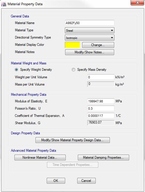
6

7 Step Six: Define frame sections. For this example, we are given that all members have the same cross-section properties. Because of this, we can select any section, so long as we apply it to all members. To illustrate adding a new section, let us select a circular steel rod and use this for all of our members. To do this, first select General under the Special set of selections. Let us use the default diameter of 25 mm. Note that we can define as many new sections as we need for a given problem. We will name this 1A.
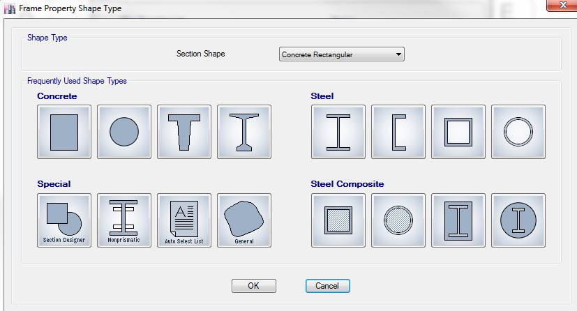
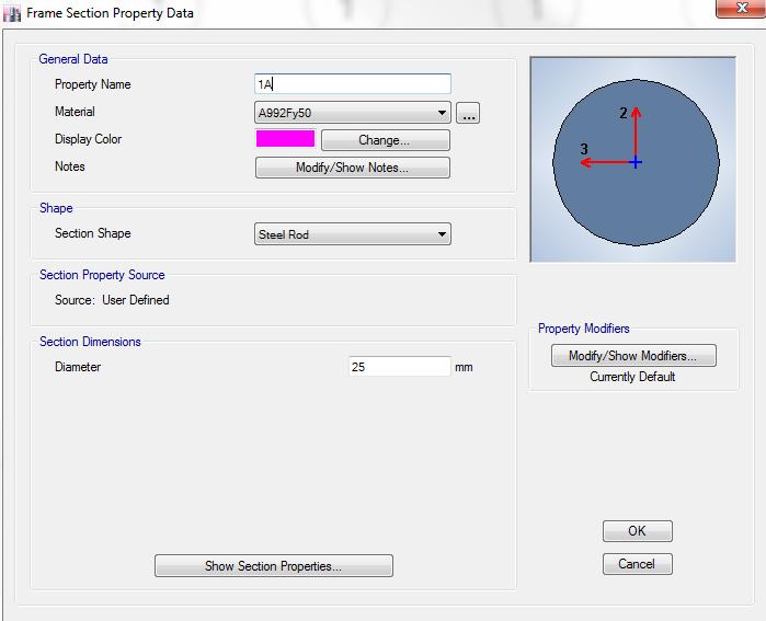
8


9 Step Seven: Now we shall draw our members. First, draw the bottom truss chord (as one continuous member). Make sure you select the frame section 1A that you defined earlier. This is selected in the Properties of Object tab. Next, divide the bottom chord it into three equal segments. To do this, select the member, click Edit, Edit Frames, then Divide Frames. For this problem, divide the bottom cord into 6 frame objects.

10 Notice that ETABS automatically placed external pin connections at the two new joints. We need to change these to internal hinges. Select the five interior points we want to change and click the Assign button. Change the joint restraints to a single joint. If you click on the check mark button, you can turn off the invisibility option and see the joints.

11 Draw the other truss members. Remember to use the frame section you defined earlier.
12 Note that for this example, we have a roller at the right support. Change the existing pin to a roller by selecting Assign, then Joint, then Restraints. Now, since this is a truss, we must release all of the internal moments since trusses do not support internal moments. The default for ETABS is a frame. That is, when you draw a structure in ETABS, it automatically assumes a frame structure. In order to release the moments and analyze this as a truss, first select all of the members. Then, under the Assign menu, select Frame and Releases/Partial Fixity. Select Moment 22, Moment 33 and Torsion and set all selections to zero. (ETABS will only allow one of the Torsion fixities to be set to zero.)
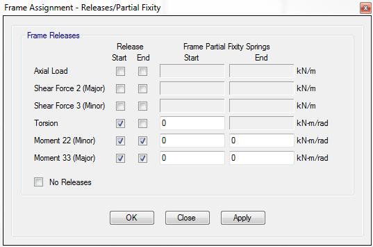
13

14 Step Eight: Next, we shall apply our loads. Select the joints where the loads are to be applied. Under the Assign menu, select Joint Loads and Force. For now, we will only consider one load combination and we will consider it to be a dead load. Step Nine: Now we run our model by selecting the play button. The model will then show the deformed shape of the truss.
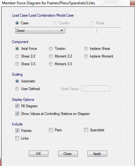
15 To determine the member forces, select the button shown below. Compression is color-coded as red and tension is color-coded yellow on the axial force diagram.
16

17 We can also determine the displacement of a joint by right clicking on a desired joint.
ADAPT-PTRC 2016 Getting Started Tutorial ADAPT-PT mode
 ADAPT-PTRC 2016 Getting Started Tutorial ADAPT-PT mode Update: August 2016 Copyright ADAPT Corporation all rights reserved ADAPT-PT/RC 2016-Tutorial- 1 This ADAPT-PTRC 2016 Getting Started Tutorial is
AASHTOWare BrR/BrD 6.8 Reinforced Concrete Structure Tutorial RC5 Schedule Based Tee Example
 AASHTOWare BrR/BrD 6.8 Reinforced Concrete Structure Tutorial RC5 Schedule Based Tee Example BrR and BrD Training RC5 Schedule Based Tee Example Topics Covered Reinforced concrete schedule based tee input
STUDY ON TALL BUILDING STRUCTURE ANALYSIS
 STUDY ON TALL BUILDING STRUCTURE ANALYSIS Liu Huafeng 1, Zhao Ning 2 ABSTRACT TBSA (Tall Building Structure Analysis) is a three-dimension analysis program for tall buildings based on a member structure
Introduction to Structural Analysis TYPES OF STRUCTURES LOADS AND
 AND Introduction to Structural Analysis TYPES OF STRUCTURES LOADS INTRODUCTION What is the role of structural analysis in structural engineering projects? Structural engineering is the science and art
NONLINEAR STATIC ANALYSIS OF R.C.C. FRAMES (Software Implementation ETABS 9.7)
") NONLINEAR STATIC ANALYSIS OF R.C.C. FRAMES (Software Implementation ETABS 9.7) Mrugesh D. Shah M.E Structure student, B.V.M Engineering College Abstract:- Nonlinear static analysis is an iterative procedure
NONLINEAR STATIC ANALYSIS OF R.C.C. FRAMES (Software Implementation ETABS 9.7) Mrugesh D. Shah M.E Structure student, B.V.M Engineering College Abstract:- Nonlinear static analysis is an iterative procedure
CONNECTION STIFFNESS IMPLEMENTATION PROCEDURE
 CONNECTION STIFFNESS IMPLEMENTATION PROCEDURE FOR Risa 3D USERS 09/29/17 Modeling of Lateral Frames Using SidePlate Connection Technology: The inherent SidePlate connection stiffness can be implemented
Seismic Analysis & Design of 10 Story RC Building
 Seismic Analysis & Design of 10 Story RC Building (Time History Analysis) Using ETABS (Metric Units) 0.3 yg 0.2 0.1 0 0 2 4 6 8 10 12-0.1-0.2-0.3 Table of Content Objective 5 Problem 5 Step by Step 11
Chapter. Masonry Design
 Chapter Masonry Design The masonry design section contains modules for the analysis of reinforced masonry beams subjected to pure bending and unreinforced masonry walls subjected to axial compression and
BrD Superstructure Tutorial
 AASHTOWare BrD 6.8 BrD Superstructure Tutorial PS12 Prestressed Concrete I Beam Using BrD LRFD Engine BrD Superstructure Training PS12 - Prestressed Concrete I Beam Using BrD LRFD Engine 1'-9" 55'-6" Total
Bridging Your Innovations to Realities
 Tutorial 2 Prestressed Concrete Bridge Bridging Your Innovations to Realities 1 Contents 2 1. Project Information 2. Definition of materials 3. Definition of Sections 4. Definition of Time dependent Materials
AASHTOWare BrD 6.8 Substructure Tutorial Solid Shaft Pier Example
 AASHTOWare BrD 6.8 Substructure Tutorial Solid Shaft Pier Example Sta 4+00.00 Sta 5+20.00 (Pier Ref. Point) Sta 6+40.00 BL SR 123 Ahead Sta CL Brgs CL Pier CL Brgs Bridge Layout Exp Fix Exp CL Brgs Abut
Composite Beam Design Manual AISC
 Composite Beam Design Manual AISC 360-10 Composite Beam Design Manual AISC 360-10 For ETABS 2016 ISO ETA122815M54 Rev. 0 Proudly developed in the United States of America December 2015 Copyright Copyright
Jerome J. Connor Susan Faraji. Fundamentals of Structural. Engineering. ^ Springer
 Jerome J. Connor Susan Faraji Fundamentals of Structural Engineering ^ Springer Contents Part I Statically Determinate Structures 1 Introduction to Structural Engineering 3 1.1 Types of Structures and
AASHTOWare BrD 6.8. BrR and BrD Tutorial. PS7-3 Stem PS Bridge Example
 AASHTOWare BrD 6.8 BrR and BrD Tutorial PS7-3 Stem PS Bridge Example BrR and BrD Training PS7 3 Stem PS Bridge Example From the Bridge Explorer create a new bridge and enter the following description data.
Types Of Roofs - Vault
 1 Types Of Roofs - Vault Implementation Of the Concrete On Vault Implementation Of Vault Earthquake Damage 2 Types Of Roofs - Joist And Block 3 Types Of Coverage Roofs-Composite 4 5 Building Structure
Design of Steel Structures Prof. S.R.Satish Kumar and Prof. A.R.Santha Kumar
 2.6 Portal frames Portal frames are the most commonly used structural forms for single-storey industrial structures. They are constructed mainly using hot-rolled sections, supporting the roofing and side
UNIVERSITY OF BOLTON WESTERN INTERNATIONAL CENTRE FZE. BEng (HONS) CIVIL ENGINEERING SEMESTER ONE EXAMINATION 2015/2016
 CIVIL ENGINEERING SEMESTER ONE EXAMINATION 2015/2016") OCD59 UNIVERSITY OF BOLTON WESTERN INTERNATIONAL CENTRE FZE BEng (HONS) CIVIL ENGINEERING SEMESTER ONE EXAMINATION 2015/2016 ADVANCED STRUCTURAL ANALYSIS AND DESIGN MODULE NO: CIE6001 Date: Tuesday 12
OCD59 UNIVERSITY OF BOLTON WESTERN INTERNATIONAL CENTRE FZE BEng (HONS) CIVIL ENGINEERING SEMESTER ONE EXAMINATION 2015/2016 ADVANCED STRUCTURAL ANALYSIS AND DESIGN MODULE NO: CIE6001 Date: Tuesday 12
COMPARATIVE REPORT CYPECAD VS. ETABS
 COMPARATIVE REPORT CYPECAD VS. ETABS Contents SIMPLE FRAME EXAMPLE... 3 1. Introduction... 4 2. Dimensions and applied loads... 4 3. Materials and applied design code... 5 4. Nodes... 7 5. Moment and shear
DESIGN FOR PROGRESSIVE COLLAPSE 1
 Your Partner in Structural Concrete Design TN447_progressive_collapse_110713 DESIGN FOR PROGRESSIVE COLLAPSE 1 Bijan O Aalami 2 This Technical Note outlines the design of column-supported conventionally
Nonlinear Buckling of Prestressed Steel Arches
 Nonlinear Buckling of Prestressed Steel Arches R. Giles-Carlsson and M. A. Wadee Department of Civil and Environmental Engineering, Imperial College London, Exhibition Road, London SW7 2AZ, UK June 22
A3D MAX FAQ. How to model column base % fixity.
 A3D MAX FAQ How to model column base % fixity. 1.0 Introduction BS 5950-1:2000 Section 5.1.3 gives recommendations for modelling base stiffness and capacity. The recommendations are given in terms of proportions
AASHTOWare BrDR 6.8 Steel Tutorial STL6 Two Span Plate Girder Example
 AASHTOWare BrDR 6.8 Steel Tutorial STL6 Two Span Plate Girder Example STL6 - Two Span Plate Girder Example (BrDR 6.5) 1'-6" 37'-0" 34'-0" 1'-6" 8 1/2" including 1/2" integral wearing surface FWS @ 25 psf
Chapter. Steel Member Design
 Chapter Steel Member Design The steel member design modules can be used for elastic and plastic design of structural steel members. Several modules act as post-processors for the frame analysis modules,
Keyboard Shortcuts for Making Selections of Objects Onscreen. Keyboard Shortcuts for Various ETABS Menu Items
 Keyboard Shortcuts for Making Selections of Objects Onscreen Keystroke E Spacebar Ctrl key + left click Ctrl key + right click Purpose Puts you in a mode to select edges of area objects Removes you from
PORTAL FRAMES 1.0 INTRODUCTION
 36 PORTAL FRAMES 1.0 INTRODUCTION The basic structural form of portal frames was developed during the Second World War, driven by the need to achieve the low - cost building envelope. Now they are the
Tech Tips SidePlate Connections FAQ 09/30/2017
 Tech Tips SidePlate Connections FAQ 09/30/2017 Page 1 of 15 Introduction to SidePlate Connection Technology SidePlate Connection Technology is ideally suited to protect structures against seismic events,
Tutorial of CUFSM4. Objectives. Example. - C-section with lips
 Tutorial of CUFSM4 Objectives - Introduce the basic methods of modeling thinwalled structures and calculating elastic critical buckling load (P cr ) or elastic critical distortional buckling moment (M
Figure 1 Shear wall segments with mono-sloped top plates
 All text, images and diagrams Copyright 2004 by Thor Matteson and ICC APPENDIX B ENGINEERING PRINCIPLES OF SHEAR WALLS WITH SLOPING TOP PLATES APA The Engineered Wood Association and others have tested
BEHAVIOR OF REINFORCED CONCRETE BEAM WITH OPENING
 International Journal of Civil Engineering and Technology (IJCIET) Volume 8, Issue 7, July 2017, pp. 581 593, Article ID: IJCIET_08_07_062 Available online at http:// http://www.iaeme.com/ijciet/issues.asp?jtype=ijciet&vtype=8&itype=7
Assessment of P-Delta Effect on High Rise Buildings
 Assessment of P-Delta Effect on High Rise Buildings Prashant Dhadve 1, Alok Rao 2, Atul Rupanvar 3, Deokate K. 4, Admile P.R 5, Dr. Nemade. P. D. 6 1,2,3,4 under graduate student, Civil Engineering S.B.
The Practicing Engineer s Solution for Advanced Nonlinear Dynamic Analysis
 www.extremeloading.com The Practicing Engineer s Solution for Advanced Nonlinear Dynamic Analysis About Extreme Loading for Structures ASI s Extreme Loading for Structures (ELS) is the first advanced nonlinear
Steel Designer. Windows Version 10. User Manual
 Steel Designer Windows Version 10 User Manual Formation Design Systems Pty Ltd 1985 2007 License & Copyright Steel Designer Program 1985-2007 Formation Design Systems Multiframe is copyrighted and all
Proposal. PricewaterhouseCoopers Oslo, Norway
 Proposal James Wilson Structural Option AE 481W Senior Thesis The Pennsylvania State University Faculty Consultant: Professor M. Kevin Parfitt Table of Contents Executive Summary...2 1. Existing Conditions...3
Pyramid Structural Engineering Applications
 Pyramid Structural Engineering Applications Abstract Pyramid is a collection of structural engineering computer applications under Windows for the analysis and design of reinforced concrete framings and
Design Example 2 Reinforced Concrete Wall with Coupling Beams
 Design Example 2 Reinforced Concrete Wall with Coupling Beams OVERVIEW The structure in this design example is a six story office building with reinforced concrete walls as its seismic force resisting
Structural Engineering Library
 Structural Engineering Library Version 5.8 by Michael D. Brooks, S.E., P.E. A product of ENERCALC, INC. ENERCALC All rights reserved. No parts of this work may be reproduced in any form or by any means
Bijan Khaleghi, Ph, D. P.E., S.E.
 0 Submission date: July, 0 Word count: 0 Author Name: Bijan Khaleghi Affiliations: Washington State D.O.T. Address: Linderson Way SW, Tumwater WA 0 INTEGRAL BENT CAP FOR CONTINUOUS PRECAST PRESTRESSED
FAQ. for Midas Gen Link, Preference and Drawings. Design + Solution for Structural Member Design with Drawing & Report
 F Design + for Midas Gen Link, Preference and Drawings Solution for Structural Member Design with Drawing & Report midas Design + Contents F 01. midas Gen Link 3 How to link with midas Gen? Member forces
S T R U C T U R. Technology. magazine. Software for the Structural Design of Masonry. The Design Basis. Copyright
 Software for the Structural Design of Masonry By Russell H. Brown, James K. Nelson, Jr. and Dennis Graber Using software can free the design engineer from the drudgery of routine calculations and enable
AASHTOWare BrR 6.8 Steel Tutorial Steel Plate Girder Using LRFR Engine
 AASHTOWare BrR 6.8 Steel Tutorial Steel Plate Girder Using LRFR Engine STL6 - Two Span Plate Girder Example 1'-6" 37'-0" 34'-0" 1'-6" 8 1/2" including 1/2" integral wearing surface FWS @ 25 psf 3'-6" 3
Hilton Baltimore Convention Center Hotel Western Podium
 Hilton Baltimore Convention Center Hotel Western Podium CHRIS SIMMONS Structural Option Faculty Consultant: Dr. Ali M. Memari Thesis Proposal TABLE OF CONTENTS EXECUTIVE SUMMARY. Page 3 INTRODUCTION..
Johns Hopkins Graduate Student Housing. Thesis Proposal. 929 North Wolfe Street Baltimore, Maryland Brad Oliver Structural Advisor: Professor Memari
 Johns Hopkins Graduate Student Housing 929 North Wolfe Street Brad Oliver Structural Advisor: Professor Memari 12/09/2011 Table of Contents Executive Summary -... 3 Introduction... 4 Structural Systems...
Marina Bay Sands Hotel Arch 631 Kayla Brittany Maria Michelle
 Marina Bay Sands Hotel Arch 631 Kayla Brittany Maria Michelle Overall Information Location: Singapore Date of Completion: 2010 Cost: $5.7 billion Architect: Moshe Safdie Executive Architect: Aedas, Pte
Strength Design of Reinforced Concrete Structures
 Chapter 6 Strength Design of Reinforced Concrete Structures 6.1 Analysis and Design General Considerations 6.1.1 Convention and Notation Unless otherwise explicitly stated, the following units shall be
Effects of Changing Design Parameters on Girders
 This issue affects users who change design parameters and reanalyze previously saved girders. Design parameters include, the building code, live load type (Snow or Construction), bottom chord live loads,
Nonlinear Analysis And Performance Assessment for 3D Structure
 Exclusive Distributor in the Middle East for CSI Software licensing, technical support and training solutions www.techiesoft.com For Sales: sales@techiesoft.com For Technical Support: support@techiesoft.com
Overview of Presentation. SCBFs are Conceptually Truss Structures
 Ultimate Strength and Inelastic Behavior of Braced Frame Gusset Plate Connections Charles W. Roeder University of Washington Department of Civil and Environmental Engineering Seattle, WA 98195 Structural
Chapter 3: Torsion. Chapter 4: Shear and Moment Diagram. Chapter 5: Stresses In beams
 Chapter 3: Torsion Chapter 4: Shear and Moment Diagram Chapter 5: Stresses In beams Torsion Torsion or Torque, T, put simply, is referred to as a twisting moment. θ The derived formulas are: Where: Torsional
Beam Detailing V1.1 User Manual For SAP 2000 ETABS RISA 3D August 2015 Barcelona -Spain
 The Structural Engineering Services Platform for Innovation and Development Beam Detailing V1.1 User Manual For SAP 2000 ETABS RISA 3D August 2015 Barcelona -Spain i Copyright Copyright SESPID, S.L.2015
DIVISION: WOOD, PLASTICS AND COMPOSITES SECTION: SHOP FABRICATED WOOD TRUSSES REPORT HOLDER: MITEK USA, INC.
 0 Most Widely Accepted and Trusted ICC ES Evaluation Report ICC ES 000 (800) 423 6587 (562) 699 0543 www.icc es.org ESR 3282 Reissued 10/2016 This report is subject to renewal 10/2018. DIVISION: 06 00
SEAU 5 th Annual Education Conference 1. ASCE Concrete Provisions. Concrete Provisions. Concrete Strengths. Robert Pekelnicky, PE, SE
 ASCE 41-13 Concrete Provisions Robert Pekelnicky, PE, SE Principal, Degenkolb Engineers Chair, ASCE 41 Committee* *The view expressed represent those of the author, not the standard s committee as a whole.
Council on Tall Buildings
 Structure Design of Sino Steel (Tianjin) International Plaza Xueyi Fu, Group Chief Engineer, China Construction Design International 1 1 Brief of Project 2 Location: Tianjin Xiangluowan Business District
DESIGN OF GRAVITY-LOAD RESISTING FRAMES FOR SEISMIC DISPLACEMENT DEMANDS
 10NCEE Tenth U.S. National Conference on Earthquake Engineering Frontiers of Earthquake Engineering July 21-25, 2014 Anchorage, Alaska DESIGN OF GRAVITY-LOAD RESISTING FRAMES FOR SEISMIC DISPLACEMENT DEMANDS
Sabah Shawkat Cabinet of Structural Engineering 2017
 3.1-1 Continuous beams Every building, whether it is large or small, must have a structural system capable of carrying all kinds of loads - vertical, horizontal, temperature, etc. In principle, the entire
INTRODUCTION DISCLAIMER
 INTRODUCTION AISIWIN is a Windows -based program for calculating section properties, load capacity, and allowable spans for cold-formed steel stud, joist and track sections. Calculations are based on the
Properties in Shear. Figure 7c. Figure 7b. Figure 7a
 Properties in Shear Shear stress plays important role in failure of ductile materials as they resist to normal stress by undergoing large plastic deformations, but actually fail by rupturing under shear
Seismic Analysis of Truss Bridges with Tall Piers
 Journal P Krishi Sanskriti Publications http: Seismic Analysis of Truss Bridges with Tall Piers Akil Ahmed 1 and Jameel Ahmed 2 1,2 Deptt of Civil Engineering Jamia Millia Islamia, Jamia Nagar, New Delhi
Steel Connection Design
 Chapter Steel Connection Design The steel connection design modules can be used for design of common welded and bolted steel connection. Steel Connection Design 5-1 Quick Reference Steel Connection Design
Concrete Frame Design Manual
 Concrete Frame Design Manual BS 8110-1997 Concrete Frame Design Manual British Standard for Structural Use of Concrete BS 8110-1997 For ETABS 2016 ISO ETA122815M22 Rev. 0 Proudly Developed in the United
DESIGN PROCESS USING ADAPT-BUILDER PLATFORM
 Structural Concrete Software System TN 182 Builder_design_process_12 111404 DESIGN PROCESS USING ADAPT-BUILDER PLATFORM Update November 13, 2004 This Technical Note walks you through the steps you would
BRBF Designer Report. Kelly Christensen
 BRBF Designer Report Kelly Christensen A project submitted to the faculty of Brigham Young University in partial fulfillment of the requirements for the degree of Master of Science Paul Richards, Committee
SECTION VIBRATION CONTROLS FOR HVAC PIPING AND EQUIPMENT
 SECTION 230548 - PART 1 - GENERAL 1.1 SUMMARY A. This Section includes the following: 1. Elastomeric Isolation pads. 2. Elastomeric Isolation mounts. 3. [Freestanding] [Restrained] [Freestanding and restrained]
Module 5 Timesheet. Step by Step Guide PSA Suite Basic for CRM Timesheet calendar view 5.2 Timer 5.3 Timesheet by line
 Step by Step Guide PSA Suite Basic for CRM 2013 Module 5 5.1 calendar view 5.2 Timer 5.3 by line PSA Suite Basic CRM 2013: V1.0 1 Module 5. Contents TIMESHEET CALENDAR VIEW... 5 INTRODUCTION... 5 1. Objectives...
Design check of BRBF system according to Eurocode 8 Use of pushover analysis
 2010 Design check of BRBF system according to Eurocode 8 Use of pushover analysis This report presents a simple computerbased push-over analysis for a steel structure with Buckling Restrained Braced Frame
Review of Elastic Bending Theory Fully Plastic Moment
 Review of Elastic Bending Theory Fully Plastic Moment MORGAN STATE UNIVERSITY SCHOOL OF ARCHITECTURE AND PLANNING LECTURE VII Dr. Jason E. Charalambides Beams References: AISC Specification and Commentary:
Structural Option April 7 th, 2010
 Gravity System (Depth Topic I) Post Tensioned Slab A new floor system was designed in an attempt to create a more consistent flooring system throughout the entire building. This new design consists of
ENG 002. INTRODUCTION to ENGINEERING. Structural Engineering Building Engineering
 ENG 002 INTRODUCTION to ENGINEERING Structural Engineering Building Engineering Introduction to Structural Engineering Forces in Structures Structural Systems Some Definitions of Important Structural Properties
Vacation/Sick/Holiday Time in TimeSaver
 Vacation/Sick/Holiday Time in TimeSaver Once an employee has requested vacation/sick or holiday time in TimeSaver, the manager will need to approve the request in order for TimeSaver to recognize the time
OPTIMUM POSITION OF OUTRIGGER SYSTEM FOR HIGH RAISED RC BUILDINGS USING ETABS (PUSH OVER ANALYSIS)
") OPTIMUM POSITION OF OUTRIGGER SYSTEM FOR HIGH RAISED RC BUILDINGS USING ETABS 2013.1.5 (PUSH OVER ANALYSIS) Karthik.N.M 1, N.Jayaramappa 2 1 Assistant Professor, Dept. of Civil Engineering Chikka Muniyappa
OPTIMUM POSITION OF OUTRIGGER SYSTEM FOR HIGH RAISED RC BUILDINGS USING ETABS 2013.1.5 (PUSH OVER ANALYSIS) Karthik.N.M 1, N.Jayaramappa 2 1 Assistant Professor, Dept. of Civil Engineering Chikka Muniyappa
EFFECTS OF COLUMN SPLICE LOCATION ON SEISMIC DEMANDS IN STEEL MOMEMNT FRAMES CONSIDERING SPLICE FLEXIBILITY
 th International Conference on Behavior of Steel Structures in Seismic Areas Shanghai, China, July -, EFFECTS OF COLUMN SPLICE LOCATION ON SEISMIC DEMANDS IN STEEL MOMEMNT FRAMES CONSIDERING SPLICE FLEXIBILITY
CHAPTER 3 ANALYSIS METHOD
 CHAPTER 3 ANALYSIS METHOD 3.1 ELASTIC STATIC ANALYSIS Elastic static analysis is done to calculate stress ratio between before and after subsidence. The structure will behave elastic when the first yield
Tutorial #3: Brand Pricing Experiment
 Tutorial #3: Brand Pricing Experiment A popular application of discrete choice modeling is to simulate how market share changes when the price of a brand changes and when the price of a competitive brand
Slab Bridge Designer 2.1 Help: Example Analysis
 August 21, 2006 Slab Bridge Designer 2.1 Help: Example Analysis Using data from the Portland Cement Association Engineering Bulletin 232, AASHTO LRFD Design of Cast-In-Place Concrete Bridges This example
Renovation of Buildings using Steel Technologies (ROBUST)
") Renovation of Buildings using Steel Technologies (ROBUST) RFCS Project RFSR-CT-2007-0043 WP 4.2 Renovation of roofs using open trusses in light steel C sections Date: 2009 Author: Mark Lawson SCI, Silwood
Renovation of Buildings using Steel Technologies (ROBUST) RFCS Project RFSR-CT-2007-0043 WP 4.2 Renovation of roofs using open trusses in light steel C sections Date: 2009 Author: Mark Lawson SCI, Silwood
Adding New Products To VirtueMart
 Adding New Products To VirtueMart To add product in VirtueMart, login to Joomla as administrator, by simply entering the url_of_your_website/administrator in your Browser. Enter the appropriate username
Analysis of Statically Determinate Structures. W.M.Onsongo. 11~1~~ii~1 ~il~~i~i~',r,~jrll. Nairobi University Press
 Analysis of Statically Determinate Structures W.M.Onsongo 11~1~~ii~1 ~il~~i~i~',r,~jrll 04965208 Nairobi University Press CONTENTS Preface xiii CHAPTER INTRODUCTION I 1.1 Structures 1.2 Loads 1.3 Analysis
Nonlinear Finite Element Modeling & Simulation
 Full-Scale Structural and Nonstructural Building System Performance during Earthquakes & Post-Earthquake Fire A Joint Venture between Academe, Industry and Government Nonlinear Finite Element Modeling
EZ-Shear Wall for ETABS v1.1
 EZ-Shear Wall for ETABS v1.1 INSTALLATION Download the installation folder and run the EXE file, which will install the program in your PC To uninstall use windows program uninstaller via control panel
HSS section calculations are based on the AISC Steel Construction Manual, 13 th edition (ASD only).
.") INTRODUCTION LGBEAMER v8 Professional edition is a Windows -based programs for analyzing single and multi-span beams using cold-formed stud, joist, track and z-shaped sections. In addition, version 8 has
INTRODUCTION LGBEAMER v8 Professional edition is a Windows -based programs for analyzing single and multi-span beams using cold-formed stud, joist, track and z-shaped sections. In addition, version 8 has
SEISMIC BEHAVIOUR OF RC BUILDING RESTING ON PLAIN AND SLOPING GROUND WITH BRACINGS AND SHEAR WALL
 SEISMIC BEHAVIOUR OF RC BUILDING RESTING ON PLAIN AND SLOPING GROUND WITH BRACINGS AND SHEAR WALL Yashaswini R 1, Dr. Mahesh Kumar G 2 1M.Tech Student, CAD Structures, Shridevi Institute of Engineering
Modern Post-Frame Structural Design Practices: An Introduction
 Modern Post-Frame Structural Design Practices: An Introduction Presented on March 4, 2015 by: Harvey B. Manbeck, PhD, PE Consultant to NFBA Professor Emeritus, Engineering Penn State University Disclaimer:
How to Create a Basic SAP Business Workflow
 How to Create a Basic SAP Business Workflow With SAP Business Workflow, SAP AG provides an efficient cross-application tool enabling integrated electronic management of business processes. SAP Business
Lateral Design of Mid- Rise Wood Structures
 Lateral Design of Mid- Rise Wood Structures Presented by Ricky McLain, MS, PE, SE Technical Director WoodWorks Texas Workshops December, 2016 Insert picture of me graduating college Follow the load Following
> 0. 1 f, they are treated as beam-columns.
 223 A- Flexural Members (Beams) of Special Moment Frames Requirements of ACI 21.5 are applicable for special moment frame members proportioned primarily to resist flexure with factored axial forces 0.
Design of buildings using EC8
 Design of buildings using EC8 & 1 can be applied to all buildings and is obligatory for buildings which do not satisfy the regularity criteria specified by EC8. The response of all modes of vibration contributing
Direct Analysis Method in Robot Structural Analysis Professional
 Direct Analysis Method in Robot Structural Analysis Professional Lin Gallant, P.E. Souza, True & Partners, Inc. Todd Blake, P.E. Souza, True & Partners, Inc. SE5788 This class will review the American
BIM - ARCHITECTUAL CREATING ROOFS
 BIM - ARCHITECTUAL CREATING ROOFS INTRODUCTION In this section, we will show you how to create Roof objects. There are many ways to create roof objects in Vectorworks. We'll start with the Create Roof
Basic Pipe Stress Analysis Tutorial
 Basic Pipe Stress Analysis Tutorial Visit our website www.sstusa.com SST Systems, Inc. SST Basic Pipe Stress Analysis Tutorial, Version 1.00, 2011-2014, SST Systems, Inc. All Rights Reserved. Disclaimer
Progressive collapse resisting capacity of modular mega frame buildings
 THE STRUCTURAL DESIGN OF TALL AND SPECIAL BUILDINGS Struct. Design Tall Spec. Build. 22, 471 484 (2013) Published online 13 April 2011 in Wiley Online Library (wileyonlinelibrary.com)..697 Progressive
Idealization of Structures and Loads
 Idealization of Structures and Loads To analyze a structure by the methods that are described in these notes it must be idealized. By utilizing the idealized structural model the deformations and internal
Deflection of a Composite Beam
 COMPUTERS AND STRUCTURES, INC., BERKELEY, CALIFORNIA SEPTEMBER 2002 COMPOSITE BEAM DESIGN BS 5950-90 Technical Note This Technical Note describes how the program checks deflection when the user selects
Property Tax Oversight Certification & Training Online Payment System. How to create and submit an order online
 Property Tax Oversight Certification & Training Online Payment System How to create and submit an order online Before You Begin Please note: DEBIT BLOCKS Some financial institutions impose a block on Automated
Dead man sheet pile wall (SI units)
") Dead man sheet pile wall (SI units) Deep Excavation LLC Software program: DeepEX 2015 Document version: 1.0 January 16, 2015 www.deepexcavation.com Deep Excavation LLC 1 A. Project description In this
Dead man sheet pile wall (SI units) Deep Excavation LLC Software program: DeepEX 2015 Document version: 1.0 January 16, 2015 www.deepexcavation.com Deep Excavation LLC 1 A. Project description In this
Multi performance option in direct displacement based design
 Multi performance option in direct displacement based design Ima Muljati 1,*, Yonatan, and Adrian Hartono 1 Civil Engineering Department, Petra Christian University, Surabaya, Indonesia Alumni of Civil
CVEN 483. Structural System Overview
 CVEN 483 Structural System Overview Dr. J. Bracci Fall 2001 Semester Presentation Overview 1. Building system primary function 2. Types of load 3. Building materials 4. Structural members 5. Structural
Training Lesson: Appointments, Set Appointments (Administrator Access Only) Revision:
 Revision:") Training Lesson: Appointments, Set Appointments (Administrator Access Only) Revision: 092506-01 This feature allows the user to set new appointments, or edit existing ones. This lesson will also describe
Training Lesson: Appointments, Set Appointments (Administrator Access Only) Revision: 092506-01 This feature allows the user to set new appointments, or edit existing ones. This lesson will also describe
22. DESIGN OF STEEL BRACED FRAMES Eccentrically Braced Steel Frames
 22. DESIGN OF STEEL BRACED FRAMES 22.1 Eccentrically Braced Steel Frames Objective is to dissipate energy in the shear or moment links and to protect the remainder of the frame from inelastic action, including
Lateral Loads Manual
 Lateral Loads Manual Lateral Loads Manual For ETABS 2016 ISO ETA122815M4 Rev. 1 Proudly developed in the United States of America October 2016 Copyright Copyright Computers & Structures, Inc., 1978-2016
Design of Laterally Unsupported Columns. TEST OF SUBASSEMBLAGE "S-l" (A brief report prepared for CRC Task Group 10)
") Design of Laterally Unsupported Columns TEST OF SUBASSEMBLAGE "S-l" (A brief report prepared for CRC Task Group 10) by Lee C. Lim This work has been carried out as part of an investigation sponsored jointly
Design of Laterally Unsupported Columns TEST OF SUBASSEMBLAGE "S-l" (A brief report prepared for CRC Task Group 10) by Lee C. Lim This work has been carried out as part of an investigation sponsored jointly