Position Paper of. FEM Product Group Cranes and Lifting Equipment - Sub-Group Tower and harbor Cranes
|
|
|
- Randolf Brown
- 6 years ago
- Views:
Transcription

1 FÉDÉRATION EUROPÉENNE DE LA MANUTENTION Product Group Krane und Hebezeuge Cranes and Lifting Equipment Grues et ponts roulants et Appareils de levage February 2014 Position Paper of FEM Product Group Cranes and Lifting Equipment - Sub-Group Tower and harbor Cranes Guidelines for considering tower crane loads on supporting structures Legal Note: This publication is only for guidance and gives an overview regarding the assessment of tower crane loads on supporting structures. It neither claims to cover any aspect of the matter, nor does it reflect all legal aspects in detail. It is not meant to, and cannot, replace own knowledge of the pertaining directives, laws and regulations. Furthermore the specific characteristics of the individual products and the various possible applications have to be taken into account. This is why, apart from the assessments and procedures addressed in this guide, many other scenarios may apply. FEM Created in 1953, the European Materials Handling Federation ( represents, defends and promotes European manufacturers of materials handling, lifting and storage equipment including cranes and lifting equipment and particular tower cranes. The FEM Product Group Cranes and Lifting Equipment's - Subgroup Tower and Harbor Cranes - mission is to represent the interest of tower crane manufacturers in Europe. Contact: Cosette Dussaugey Cisma 45 Rue Louis Blanc F Courbevoie cosette.dussaugey@cisma.fr Tel: +33(0) Fax: +33(0)
2 0-Foreword / Introduction This position paper reflects the opinion of FEM with regard to state of the art. It clarifies the different responsibilities regarding the design of supporting structures for the installation of tower cranes on European construction sites. This document provides information on the interpretation and use of the static data contained in the instruction manual of tower cranes. The explanations are intended to contribute to plan safe and economical crane operations by giving guidelines for determining loads for the design of crane supporting structures. These guidelines should be considered as minimum requirements. National regulations may require different rules and/or safety factors. I-Tower cranes loads on supporting structures I-1 General Tower crane loads on supporting structures shall be determined by tower crane manufacturers using EN14439 Cranes - Safety - Tower Cranes which is an harmonised standard giving presumption of conformity to the EU law Machinery Directive 2006/42/EC. This calculation differs from the Eurocodes 1 which are not fully applicable due to a different approach regarding the types of load actions and load combinations as well as the rules regarding the combination of these load actions and their partial safety factors. I-2 Loads description This reflects the opinion of FEM. Loads on tower crane supporting structures are necessary to enable the crane operating companies to perform all essential proof calculations. Thereby the different requirements on the loads regarding the different types of proofs have to be considered. Loads on crane support structures are usually: Foundation loads of cranes erected on concrete foundation Corner loads of cranes using undercarriage or foundation cross Anchoring loads of cranes climbing in- or outside a building These loads result from combinations of the following elementary load actions: Effects of gravity on the crane dead weight and on the hoist load Inertia loads from crane movements/accelerations of all crane drives on the crane structure and the hoist load Effects of the wind pressure on the crane structure and the hoist load The load combinations, as a set of associated and dependent load actions, leading to the maximum resulting load effects of the tower crane on supporting structure are highly dependent on the tower crane configuration. Thereby the general design of the tower crane, the jib length, the tower height, the position of the rotating part 1 Eurocode 2
3 of the slewing tower crane related to the fixed part of the crane structure, the size and position of the hoist load, the combination of several inertia loads and/or the angle of attack of the wind are the most important parameters. Usually the maximum loads, resulting from a large number of crane configurations, are given for each of these following situations: In-service loads, including maximum in-service-wind Out-of-service loads, with storm from rear and storm from front or alternatively storm from all sides Erection loads, mainly provided as foundation loads for cranes erected on concrete foundation Generally loads on crane supporting structures provided by tower crane manufacturers are characteristic loads without any partial safety factors included nor dynamic factors, i.e. amplification factor due to the dynamic response of the cranes structure under the load in consideration. Likewise, second order effects, as an increase of the loading effects due to the cranes deformations, are usually not included unless clearly mentioned. A separation of these resulting loads into elementary load actions is not intended due to the above described dependency of the load action onto the crane and crane configuration. I-3 Permanent and live loads The reaction forces (corner reactions, foundation loads, or anchoring loads) of a tower crane predominantly consist of the resulting load moment. 3
4 The direction of the load moment is not constant as it depends at each instant on the slewing crane part position relative to the fixed part of the tower crane. This behaviour applies to in-service as well as to out-ofservice situations. It is essential to consider the variable dead weight load moment effect as a major difference to a usually invariant dead weight load effect considered for buildings. As a consequence, all loads including the dead weight moment are seen as a live load for the supporting structure except the dead weight force to be considered as a permanent effect. II- Design of supporting structure II-1 General The design and proof calculation of supporting structures for tower cranes are conducted or contracted by the crane operating company usually in accordance with the Eurocodes together with national rules laid down in national annexes. As an assumption, all tower cranes erected on construction sites are assimilated to temporary structures. Therefore the requirements regarding fatigue or e.g. a minimum reinforcement grade of concrete foundations as required for durable buildings usually do not apply. II-2 Loads classification According to EN1990 2, load actions are classified as (with indication of typical partial safety factors ): Permanent (G) G = 1,35 Variable (Q) Q = 1,5 Accidental (A) A = 1,0 Note 1: These partial safety factors are applicable to most of ultimate limit state load combinations, refer to clause II-3. According to EN the load actions and load combinations are classified as (with indication of typical partial safety factors ): Regular loads (A) p = 1,34 Occasional loads (B) p = 1,22 Exceptional loads (C) p = 1,10 Note 2: The partial safety factors p indicated above give a simplified overview of the full set of partial safety factors that can slightly differ depending on individual load action under consideration. Note 3: For standard applications of tower cranes for construction works, no accidental situations (e.g. earth quake) are considered for the foundation design. 2 EN 1990: A1: A1:2005/AC:2010 Eurocode Basis of structural design 3 EN Cranes - Safety - Tower Cranes 4
5 II-3 Ultimate limit states proof (EN 1990: A1: A1:2005/AC:2010 Clause 6.4): The design of all crane supporting structural points is mainly governed by the ultimate limit states proof comprising: Stability (EQU) Internal failure or excessive deformation of the structure (STR) Failure or excessive deformation of the ground (GEO) The general load combinations are defined as: G,j G k,j ''+'' Q,1 Q k,1 ''+'' Q,i 0 Q k,i with = partial safety factor Q k,1 = main variable action Q k,i ; i > 1 = accompanying variable action(s) 0 = factor for combination of accompanying variable action(s) with the main variable action The reaction forces of a tower crane on a supporting structure predominantly consist of the resulting bending moment generated by the dead weight load, the wind load and inertia loads. As indicated in chapter I, due to the multitude of crane configurations only the most unfavourable resulting load combinations are usually provided for each typical crane situation as crane in service, crane out of service and crane during erection. For each of these typical crane situations, the effects of all permanent and variable load actions are considered as one single variable load action on the supporting structure with their full amount. (refer also to EN :2006/AC: Clause (6) Actions induced by cranes and machinery) Due to this consideration, the load combinations can be simplified by: G,j G k,j ''+'' Q,i Q k,i with Q,i Q k,i = result of all variable actions without reduction factor 0 II.3.1 Proof of strength of local supporting structures for undercarriage or cruciform base Generally the resulting load moment from the crane on local point of supporting structures induces tensile and compressive loads on the point of contact between the tower crane and the supporting structures. Together with the rotational behaviour, all load moment effects should be multiplied uniformly with the partial safety factor for live loads ( Q ). Only the dead weight force should be considered as a permanent effect and should be multiplied by a different partial safety factor ( G ). The maximum tensile and compressive load effects as well the local shear load effect result from load combinations LC1 and LC2 according to table 1. 4 EN :2006/AC:2012 Eurocode 1 Actions on structures part 3 Actions induced by cranes and machinery 5
6 Permanent load from the crane (dead weight vertical action) Max compressive load LC1 Max tensile load LC2 - Favourable Ginf - Unfavourable Gsup Variable load from the crane (including weight moment action) - Favourable - Unfavourable Qsup Qsup Table 1: Load combinations for tower crane local actions on supporting structures However for tower cranes on undercarriage or cruciform base no permanent corner loads can be defined due to the rotation of the crane and the possibility of lifting at each corner. In this case the local load effect (corner reaction) has to be multiplied with the factors for live loads ( Q ) entirely. Due to the nature of the different load combinations acting on a tower crane, it is necessary to consider different values for partial safety factors depending on the probability of occurrence of the load combination in accordance with the classification given in tower crane design standards. Crane loads provided without any dynamic factor nor second order effect (that can affect resulting loads for high cranes ), should be increased by a general amplification factor. When this factor is not indicated by the crane manufacturer, a minimum value of 1,10 should be used for factor (only applicable for the superior partial safety factor). Simplified table of partial safety factors proposed for the design of local supporting structures of undercarriage or cruciform base: Partial safety factors if second order and dynamic effects are included by the crane manufacturer 1) Partial safety factors if second order and dynamic effects are not included by the crane manufacturer ( = 1,10) Load case Gsup Ginf Qsup Gsup Ginf Qsup In service (in operation) 1,35 1,50 Out of service (storm from rear) Out of service (storm from front/side) In erection (assembly) Not applicable for tower cranes on undercarriage or cruciform base 1,22 1,10 Not applicable for tower cranes on undercarriage or cruciform base 1,35 1,22 1,22 1,35 Table 2: Partial safety factors for cranes on undercarriage or cruciform base 6
7 1) These partial safety factors are related to the actual crane design standards EN and EN , amplified by a factor of 1,1 to consider the situation of construction site. For cranes on chassis, a proof of stability is not required as the crane stability checked by the crane manufacturer already defines the ballast required on the chassis according to crane standard. II.3.2 Proof of strength of concrete block foundation For tower cranes on concrete block foundation, it is also necessary to check the concrete block strength, in addition to the local effect of each tower crane structure point of connection to the supporting structure. Crane loads provided without any dynamic factor nor second order effect (that can affect resulting loads for high cranes ), can be increased by a general amplification factor. In case this factor is not indicated by the crane manufacturer, a minimum value of 1,10 should be used for factor (only applicable for the superior partial safety factor). Table of partial safety factors proposed for the design of concrete block foundation with embedded local supporting structures (e.g. foundation anchors): Partial safety factors if second order and dynamic effects are included by the crane manufacturer 1) Partial safety factors if second order and dynamic effects are not included by the crane manufacturer ( = 1,10) Load case Gsup Ginf Qsup Gsup 2) Ginf Qsup In service (in operation) Out of service (storm from rear) Out of service (Storm from front/side) In erection (assembly) 1,35 1,0 1,35 1,35 1,0 1,50 1,22 1,0 1,22 1,22 1,0 1,35 1,10 1,0 1,10 1,10 1,0 1,22 1,22 1,0 1,22 1,22 1,0 1,35 Table 3: Partial safety factors for cranes on concrete block foundation 1) These partial safety factors are related to the actual crane design standards EN and EN , amplified by a factor of 1,1 to consider the situation of construction site. 2) Amplification factor has not to be considered for dead weight force on foundation due to no increase with theory second order. This check shall be consistent with the load combinations considered for the check of each local effect on supporting structures. 5 EN14439 Cranes - Safety - Tower Cranes 6 EN Cranes General design 7 EN14439 Cranes - Safety - Tower Cranes 8 EN Cranes General design 7
8 II.3.3 Proof of stability of concrete block foundation The global stability under ultimate limit state shall be checked considering the appropriate criteria depending on the concrete block foundation configuration in the ground. As a general guideline for shallow foundation, the resulting load eccentricity shall not be greater than 1/2 of the concrete block outside dimension in any direction, when considering the different load combinations used for the proof of strength. Note 1: This guideline is defined considering the temporary installation of the tower crane on the construction site. In case of special application (e.g. permanent installation on a stock yard) a maximum eccentricity of 1/3 rd may be necessary. Note 2: In general, the proof of global stability checked for the serviceability limit state will govern the stability proof. II-4- Serviceability limit states proof (EN 1990: A1: A1:2005/AC: Clause 6.5) The serviceability limit state proof for tower crane supporting structures mainly consists in checking the risk of ground deformation and global stability. The load combinations are simplified by: G k,j ''+'' Q k,1 ''+'' 0 Q k,i For the same reason as explained in II-3, the load combinations can then be simplified by: G k,j ''+'' Q k,i with Q k,i = result of all variable actions without reduction factor As a general guideline for shallow foundation, the resulting load eccentricity shall not be greater than 1/3 rd of the concrete block outside dimension in any direction. Note 1: This guideline is defined considering the temporary installation of the tower crane on the construction site. In case of special application (e.g. permanent installation on a stock yard), a maximum eccentricity of 1/6 th for the load combination crane in service, assumed as quasi-permanent ELS combination, may be necessary. Note 2: For cranes on chassis, a proof of stability is not required as the crane stability checked by the crane manufacturer already defines the ballast required on the chassis according to crane standard. 9 EN 1990: A1: A1:2005/AC:2010 Eurocode basis of structural design 8

9 Example 1: Crane on undercarriage or cruciform base (typical tower crane manufacturer data without theory second order effects) Corner reactions (characteristic load values, numerical example) Crane type: Tower system: Base tower: tower selection length: Crane base: Track: 6 m No. of Hook Central Corner pressure in operation [kn], M D = 325 knm tower height ballast Position of jib Hor. force Wheel gauge: 6 m Jib: Corner pressure out of operation [kn], M D = 0 knm Position of jib sections [m] [to] Corner [kn] Corner [kn] 5 40,30 86,110 A A B B C C D D Hor. force Proposal of partial safety factors for corner reactions acc. to 1st order theory Safety factors if second order and dynamic effects are not included by the crane manufacturer ( = 1,10) Load case Gsup Ginf Qsup In service (in operation) In erection (assembly) 1,35 Not applicable for cranes on Out of service undercarriage or cruciform 1,35 (storm from rear) base Out of service (Storm from front/side) See clause II table 2 If out of operation (out of service) is not clearly divided in storm from rear or storm from front/side the safety factor for storm from rear has to be taken into account (save assumption). 1,5 1,22 9
10 Max. corner reactions (design load values, numerical example) No. of Hook Central Design Corner pressures in operation [kn] tower height ballast Position of jib Hor. force Design Corner pressures out of operation [kn] Position of jib sections [m] [to] Corner [kn] Corner [kn] 5 40,30 86,110 max max Note 1: The above given global characteristic horizontal load and torque moment is recalculated into a max. local horizontal design shear force considering 4 corners acting equally. Determination of horizontal force: In operation (in service): Out of operation (out of service): 2 M D Hk Hd Q,sup 4* a 4 2 with a = system width of undercarriage H d Q,sup H 4 Attention shall be given to the effective boundary conditions attached to each of the 4 corners (e.g. no horizontal fixation of all corners or for a mobile configuration on rail). Other transmission models may be used accordingly, taking into account the prevailing bearing conditions (e.g. sliding capability of corners or H-force application perpendicular to the rail). Note 2: As no permanent corner load can be calculated it will be set to 0. Thus the corner reaction is seen as an entire live load and is multiplied with the corresponding partial safety factor Q. k 2 Hor. force 10
")
11 Example 2: Crane on concrete foundation block (typical tower crane manufacturer data without theory second order effects) 11

12 12
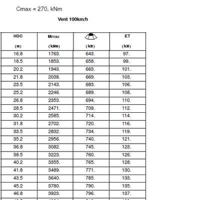
13 System of tower: D [m] = 1,84 CRANE IN SERVICE CRANE OUT OF SERVICE CRANE OUT OF SERVICE CRANE DURING Storm from rear Storm from side/front ERECTION Foundation loading without theory Cmax C k 270 knm C k 0 knm C k 0 knm C k 270 knm second order. Partial safety factors Weight (W) Vk 885 kn Vk 765 kn Vk 765 kn Vk 474 kn according table 3 clause II.3.2 with Moment (Mmax) M k 2086 knm M k 3605 knm M k 3355 knm M k 2175 knm = 1,10 should be used Shear (Tmax) Hk 57 kn Hk 193 kn Hk 128 kn Hk 31 kn Ultimate Loads Local Strength (per corner) G Q G Q G Q G Q max. resulting compressive loads [kn] see formula [1] 1,35 1, ,22 1, ,10 1, ,22 1, max. resulting tension loads [kn] see formula [2] 1,00 1, ,00 1, ,00 1, ,00 1, max. resulting shear load [kn] see formula [3] -- 1, , , ,35 70 Global Strength G Q G Q G Q G Q vertical load [kn] Gsup*V k 1, , , , overturning moment [knm] Qsup*M k -- 1, , , , horizontal load [kn] Qsup*H k -- 1, , , ,35 42 slewing moment [knm] Qsup*C k -- 1, , , , Global Stability G Q G Q G Q G Q vertical load [kn] Ginf*V k 1, , , , overturning moment [knm] Qsup*M k -- 1, , , , horizontal load [kn] Qsup*H k -- 1, , , ,35 42 slewing moment [knm] Qsup*Ck -- 1, , , , Serviceability Loads Global Stability G Q G Q G Q G Q vertical load [kn] G*V k 1, , , , overturning moment [knm] Q*M k -- 1, , , , horizontal load [kn] Q*H k -- 1, , , ,00 31 slewing moment [knm] Q*Ck -- 1, , , , Mk Vk [1] Fc, d Q sup G sup [2] D 2 4 F t, d Q sup Mk G D 2 inf Vk 4 [3] Sd, max Q sup H 2 k Ck D Note : as a conservative approach, formula [3] is proposed considering here only 2 feet acting for the horizontal load 13
2. SAFETY VERIFICATIONS OF SHALLOW FOUNDATIONS Bearing capacity failure
 Seismic design of shallow foundations Bearing capacity of soil Pedro Miguel Sereno July 216 ABSTRACT Traditionally the verification on the bearing capacity of shallow foundation in a seismic situation
DESIGN OF WALLS FOR SHEAR
 mortarless masonry Design Manual Part 3 (IS 456:2000) Section 5 Page: 1 SECTION 5. DESIGN OF WALLS FOR SHEAR Shear walls: Load-bearing walls are mostly designed to carry axial compression loads, however
EN REINFORCED MASONRY DESIGN EXAMPLE 1 (NOTE: THIS USES THE UK NATIONAL ANNEX NDP VALUES)
") 42.50 10.00 3.00 20.00 EN 1996-1-1 REINFORCED MASONRY DESIGN EXAMPLE 1 (NOTE: THIS USES THE UK NATIONAL ANNEX NDP VALUES) Reinforced Masonry - Reinforced Brickwork Stem Cantilever Pocket-Type Retaining
42.50 10.00 3.00 20.00 EN 1996-1-1 REINFORCED MASONRY DESIGN EXAMPLE 1 (NOTE: THIS USES THE UK NATIONAL ANNEX NDP VALUES) Reinforced Masonry - Reinforced Brickwork Stem Cantilever Pocket-Type Retaining
R-Group Finland Oy. REA Lifting Inserts Technical Manual According to Eurocodes, EU Machinery directive 2006/42/EC and VDI/BV-BS 6205 CE Approved
 R-Group Finland Oy REA Lifting Inserts Technical Manual According to Eurocodes, EU Machinery directive 2006/42/EC and VDI/BV-BS 6205 CE Approved 10.2.2017 2 Table of Contents 1 DESCRIPTION OF THE SYSTEM...
Unit 48: Structural Behaviour and Detailing for Construction. Limit State Design
 2.1 Introduction Limit State Design Limit state design of an engineering structure must ensure that (1) under the worst loadings the structure is safe, and (2) during normal working conditions the deformation
R-Group Finland Oy. RTA, RWTL and RWTS Lifting anchors Design instructions
 R-Group Finland Oy RTA, RWTL and RWTS Lifting anchors Design instructions According to Eurocodes, EU Machinery directive 2006/42/EC and VDI/BV-BS 6205 CE Approved 28.12.2016 2 Table of contents 1 DESCRIPTION
Single-Span Steel Beam STT
 Single-Span Steel Beam STT User Manual for Frilo design applications Friedrich + Lochner GmbH 2011 Frilo on the web www.frilo.com E-Mail: info@frilo.de STT manual 2a/2011 STT Single-Span Steel Beam 1 Frilo-Application:
European Technical Assessment ETA-10/0422 of 08/01/2016
 ETA-Danmark A/S Göteborg Plads 1 DK-2150 Nordhavn Tel. +45 72 24 59 00 Fax +45 72 24 59 04 Internet www.etadanmark.dk Authorised and notified according to Article 29 of the Regulation (EU) No 305/2011
Summary. 1. Introduction. Enrique GONZÁLEZ DUEÑAS Civil Engineer LRA Infrastructures Consulting Madrid, SPAIN
 Tomás RIPA ALONSO Partner. Civil Engineer LRA Infrastructures Consulting Madrid, SPAIN tomasripa@lraingenieria.es Tomás Ripa received his civil engineering degree from the Technical University of Madrid,
3. Bond, Anchorage and Shear This chapter will discuss the following topics:
 3. Bond, Anchorage and Shear This chapter will discuss the following topics: Outline the theory of calculating the anchorage bond length. Determination of anchorage bond length, tension lap length and
Railway Bridge to EUROCODE. Presenter: Robert Salca technical support engineer, Midas UK
 Railway Bridge to EUROCODE Presenter: Robert Salca technical support engineer, Midas UK In order to make sure that the sound system is working well a poll will appear shortly on your screens. Please vote
Lecture Retaining Wall Week 12
 Lecture Retaining Wall Week 12 Retaining walls which provide lateral support to earth fill embankment or any other form of material which they retain them in vertical position. These walls are also usually
Recommendations for additional fire protection of structural elements
 ANNEX 6 Recommendations for additional fire protection of structural elements 1 Scope This Annex contains a series of recommendations applicable to structural concrete structures which, for general fire
Schöck Isokorb type CV
 Schöck Isokorb type The Schöck Isokorb type is suitable for supported reinforced concrete slabs. (C concrete slab) It transmits positive shear force (vertical shear). 71 72 Section/element arrangement
FEM European Materials Handling Federation
 FEM European Materials Handling Federation www.fem-eur.com 02.12.2014 N 0075 Guideline CE-Declaration - Crane systems connected in Buildings or free standing supporting structures Legal Note: This paper
European Technical Assessment ETA-14/0453 of 11/12/2014
 ETA-Danmark A/S Göteborg Plads 1 DK-21590 Nordhavn Tel. +45 72 24 59 00 Fax +45 72 24 59 04 Internet ww.etadanmark.dk Authorised and notified according to Article 29 of the Regulation (EU) No 305/2011
ISO INTERNATIONAL STANDARD. Cranes Limiting and indicating devices Part 4: Jib cranes
 INTERNATIONAL STANDARD ISO 10245-4 First edition 2004-11-01 Cranes Limiting and indicating devices Part 4: Jib cranes Appareils de levage à charge suspendue Limiteurs et indicateurs Partie 4: Grues à flèche
UNIVERSITY OF BOLTON WESTERN INTERNATIONAL CENTRE FZE. BEng (HONS) CIVIL ENGINEERING SEMESTER ONE EXAMINATION 2015/2016
 CIVIL ENGINEERING SEMESTER ONE EXAMINATION 2015/2016") OCD59 UNIVERSITY OF BOLTON WESTERN INTERNATIONAL CENTRE FZE BEng (HONS) CIVIL ENGINEERING SEMESTER ONE EXAMINATION 2015/2016 ADVANCED STRUCTURAL ANALYSIS AND DESIGN MODULE NO: CIE6001 Date: Tuesday 12
OCD59 UNIVERSITY OF BOLTON WESTERN INTERNATIONAL CENTRE FZE BEng (HONS) CIVIL ENGINEERING SEMESTER ONE EXAMINATION 2015/2016 ADVANCED STRUCTURAL ANALYSIS AND DESIGN MODULE NO: CIE6001 Date: Tuesday 12
EN Eurocode 7. Section 8 Anchorages Section 9 Retaining structures. Brian Simpson Arup Geotechnics
 EUROCODES Background and Applications EN1997-1: Anchorages and Retaining structures Brussels, 18-20 February 2008 Dissemination of information workshop 1 EN 1997-1 Eurocode 7 Section 8 Anchorages Section
16. Design of Pipeline Structures.
 16. Design of Pipeline Structures. a. General. 1) The following guidelines are for the design of structures for water and sewer pipelines including structural concrete and miscellaneous metals design.
COLUMN SHOES HPKM, PPKM, PEC
 COLUMN SHOES HPKM, PPKM, PEC Version 9/2007 (Update 7/2009) Replaces brochure /2006 HPKM, PPKM, PEC -column shoes Benefits of Peikko -column joints Saves time, costs and materials Easy and fast adjustments
DS/EN DK NA:2013
 National Annex to Eurocode 6: Design of masonry structures - Part 1-1: General rules for reinforced and unreinforced masonry structures Foreword This national annex (NA) is a revision and compilation of
CHAPTER 11: PRESTRESSED CONCRETE
 CHAPTER 11: PRESTRESSED CONCRETE 11.1 GENERAL (1) This chapter gives general guidelines required for the design of prestressed concrete structures or members with CFRM tendons or CFRM tendons in conjunction
European Technical Assessment ETA-10/0415 of 25/02/2016
 ETA-Danmark A/S Göteborg Plads 1 DK-2150 Nordhavn Tel. +45 72 24 59 00 Fax +45 72 24 59 04 Internet www.etadanmark.dk Authorised and notified according to Article 29 of the Regulation (EU) No 305/11 of
Lattice Beam User Guide USG001-
 Lattice Beam User Guide Foreword DESSA offers efficient lightweight temporary roofing, encapsulation solutions, aluminium lattice girders and safety products. DESSA s unique and distinctive aluminium
E TA TECHNICAL REPORT. Design of Metal Anchors For Use In Concrete Under Seismic Actions. TR 45 Edition February 2013
 E TA TECHNICAL REPORT Design of Metal Anchors For Use In Concrete Under Seismic Actions TR 45 Edition EUROPEAN ORGANISATION FOR TECHNICAL APPROVALS Table of Contents 1 Introduction 3 2 Scope 3 2.1 General...
BEHAVIOUR AND DESIGN OF ANCHORS FOR LIFTING AND HANDLING IN PRECAST CONCRETE ELEMENTS
 BEHAVIOUR AND DESIGN O ANCHORS OR LITING AND HANDLING IN PRECAST CONCRETE ELEMENTS Dieter Lotze Halfen GmbH & Co. KG, Wiernsheim, Germany Abstract Lifting anchors are widely used in the precast concrete
Geotechnical Engineering Software GEO5
 Geotechnical Engineering Software GEO5 GEO5 software suite is designed to solve various geotechnical problems. The easy -to -use suite consists of individual programs with an unified and user-friendly
Structural behaviour and failure mechanisms of concrete monoblock railway sleepers
 Structural behaviour and failure mechanisms of concrete monoblock railway sleepers Olli Kerokoski, Antti Nurmikolu and Tommi Rantala Department of Civil Engineering, Tampere University of Technology, P.O.
Fundamentals of Structural Design Part of Steel Structures
 Fundamentals of Structural Design Part of Steel Structures Civil Engineering for Bachelors 133FSTD Teacher: Zdeněk Sokol Office number: B619 1 Syllabus of lectures 1. Introduction, history of steel structures,
Shear resistance of masonry walls and Eurocode 6: shear versus tensile strength of masonry
 DOI 10.1617/s11527-008-9430-6 ORIGINAL ARTICLE Shear resistance of masonry walls and Eurocode 6: shear versus tensile strength of masonry Miha Tomaževič Received: 7 April 2008 / Accepted: 17 September
SOIL PRESSURE IN EMBANKMENT STABILIZATIONS
 SOIL PRESSURE IN EMBANKMENT STABILIZATIONS Analysis of the 3D shadowing effect of piles Dipl.-Ing. M. Filus Fides DV-Partner GmbH ABSTRACT: Pile checks required by the codes alone are usually not sufficient
How to calculate anchorage and lap lengths to Eurocode 2
 How to calculate anchorage and lap lengths to Eurocode 2 This is the first in a series of articles, previously printed in The Structural Engineer magazine, which will be collated to form a Concrete Structures
Structural Design of Pergola with Airfoil Louvers
 International Journal of Advanced Structures and Geotechnical Engineering ISSN 2319-5347, Vol. 04, No. 03, July 2015 Structural Design of Pergola with Airfoil Louvers MUHAMMAD TAYYAB NAQASH Aluminium TechnologyAauxiliary
European Technical Assessment. ETA 15/0226 of General Part TCM400PE, TCM600PE. Trade name of the construction product
 Member of Wellington, 19 ES 08018 Barcelona Tel: (+34) 93 309 34 04 qualprod@itec.cat www.itec.cat www.eota.eu European Technical Assessment ETA 15/0226 of 17.04.2015 General Part Trade name of the construction
Advance Design of RC Structure Retaining Wall
 1 Retaining Wall Retaining Walls What are retaining walls Retaining walls are soil-structure systems intended to support earth backfills. Type of retaining walls Gravity retaining wall gravity walls rely
Available online at ScienceDirect. Procedia Engineering 172 (2017 )
") Available online at www.sciencedirect.com ScienceDirect Procedia Engineering 172 (2017 ) 521 528 Modern Building Materials, Structures and Techniques, MBMST 2016 ETA tests and design of HPKM Column Shoe
Available online at www.sciencedirect.com ScienceDirect Procedia Engineering 172 (2017 ) 521 528 Modern Building Materials, Structures and Techniques, MBMST 2016 ETA tests and design of HPKM Column Shoe
Bridge articulation No. 1.04
 Bridge articulation Scope This Guidance Note gives advice on the selection of the articulation arrangements, the choice of bearing types and dispositions of bearings, for bridges where relative movement
European Technical Assessment. ETA-12/0398 of 29/12/2017. General Part. Instytut Techniki Budowlanej. Technical Assessment Body issuing the
 European Technical Assessment General Part of 29/12/2017 (English language translation the original version is in Polish language) Body issuing the European Trade name of the construction product Product
This guide can be used to prepare a specification for incorporating free standing jib cranes into a competitively bid construction project.
 SECTION 14651 FREE STANDING JIB CRANE ***** Gorbel, Inc. manufacturers a broad range of material handling cranes including monorail, bridge, gantry, and jib cranes. Numerous work station and industrial
ALLOWABLE STRESS DESIGN OF CONCRETE MASONRY LINTELS. TEK 17-1C Structural (2009) Related TEK: Uniform load. Triangular load. Concentrated loads
 Related TEK: Uniform load. Triangular load. Concentrated loads") An information series from the national authority on concrete masonry technology ALLOWABLE STRESS DESIGN OF CONCRETE MASONRY LINTELS TEK 17-1C Structural (2009) INTRODUCTION Lintels and beams are horizontal
An information series from the national authority on concrete masonry technology ALLOWABLE STRESS DESIGN OF CONCRETE MASONRY LINTELS TEK 17-1C Structural (2009) INTRODUCTION Lintels and beams are horizontal
DESIGN FOR PROGRESSIVE COLLAPSE 1
 Your Partner in Structural Concrete Design TN447_progressive_collapse_110713 DESIGN FOR PROGRESSIVE COLLAPSE 1 Bijan O Aalami 2 This Technical Note outlines the design of column-supported conventionally
Design of large scale wind turbine towers in seismic areas
 Design of large scale wind turbine towers in seismic areas C.C. Baniotopoulos, I. Lavassas, G. Nikolaidis, P.Zervas Institute of Metal Structures, Dept. of Civil Engineering, A.U.Th., Thessaloniki, Greece
How to Design a Singly Reinforced Concrete Beam
 Time Required: 45 minutes Materials: -Engineering Paper -Calculator -Pencil -Straight Edge Design For Flexural Limit State How to Design a Singly Reinforced Concrete Beam Goal: ΦMn > Mu Strength Reduction
NEW for high shearing forces REINFORCEMENT SYSTEMS
 PRODUCTS NEW for high shearing forces REINFORCEMENT SYSTEMS PRODUCT VIDEO WWW.NEVOGA.COM REINFORCEMENT SYSTEM PLEXUS, PYRAPLEX, FTW PLEXUS PLEXUS is a prefabricated rebar continuity system for reinforced
S-60-TO : 1 ton tower system
 S-60-TO : 1 ton tower system INSTRUCTION MANUAL ALC Truss S-60-TO Tower Manual Version 1.4 1 FOREWORD This manual is intended for sound-, lighting- and rigging technicians. The set-up and operation of
DESIGN SPECIFICATION FOR FOUNDATIONS
 FOR HINDUSTAN PETROLEUM CORPORATION LTD. VISAKH REFINERY DHT PROJECT JOB NO. : 6261 DOCUMENT NO. : A-6261-110-006 TOTAL NO. OF PAGES: 11 (INCLUDING THIS PAGE) 0 16-11-2009 FOR APPROVAL
DURABILITY AND SERVICEABILITY
 DURABILITY AND SERVICEABILITY Introduction of Durability Durability requirements are to ensure that a structure has satisfactory durability and serviceability performance under normal circumstances throughout
Eurocode 6 Design of masonry structures
 BRITISH STANDARD Eurocode 6 Design of masonry structures BS EN 1996-1-1:2005 Incorporating corrigenda February 2006 and July 2009 Part 1-1: General rules for reinforced and unreinforced masonry structures
Seismic assessment of horizontal cylindrical reservoirs
 Seismic assessment of horizontal cylindrical reservoirs Christos Baltas 1, Pierino Lestuzzi 1, 2, Martin G. Koller 1 1 2 Résonance Ingénieurs-Conseils SA 21 rue Jacques Grosselin, 1227 Carouge, Suisse
This guide can be used to prepare a specification for incorporating free standing jib cranes into a competitively bid construction project.
 GORBEL PRODUCT SPECIFICATIONS 2010 Gorbel, Inc., P.O., Box 593, Fisher, New York 14453-0593 PHONE: 800-821-0086, FAX: 585-924-6273; WEBSITE: www.gorbel.com November SECTION 41 22 31PRIVATE FREE STANDING
Peter Juhren Corporate Service Manager Morrow Equipment Co. L.L.C. Salem, OR USA. What s New in Tower Crane Standards?
 Peter Juhren Corporate Service Manager Morrow Equipment Co. L.L.C. Salem, OR USA What s New in Tower Crane Standards? The opinions expressed in this presentation are those of the presenter, Peter Juhren,
Council on Tall Buildings
 Structure Design of Sino Steel (Tianjin) International Plaza Xueyi Fu, Group Chief Engineer, China Construction Design International 1 1 Brief of Project 2 Location: Tianjin Xiangluowan Business District
Masonry Wall Bracing. A Simplified Approach To Bracing Masonry Walls Under Construction. Masonry Bracing Task Force.
 Masonry Wall Bracing A Simplified Approach To Bracing Masonry Walls Under Construction Produced by the Masonry Wall Bracing A Simplified Approach to Bracing Masonry Walls Under Construction Produced by
Types of Foundations
 Shallow Foundations Types of Foundations Foundations can be classified to two major categories: Shallow. Deep. 1 Introduction If the soil stratum is suitable for supporting the structural loads from the
European Technical Assessment ETA-16/0865 of 08/11/2016
 ETA-Danmark A/S Göteborg Plads 1 DK-21590 Nordhavn Tel. +45 72 24 59 00 Fax +45 72 24 59 04 Internet www.etadanmark.dk Authorised and notified according to Article 29 of the Regulation (EU) No 305/2011
Final PT Draft (Stage 34) Page 1. EUROPEAN STANDARD pren NORME EUROPÉENNE EUROPÄISCHE NORM. English version
 Page 1. EUROPEAN STANDARD pren NORME EUROPÉENNE EUROPÄISCHE NORM. English version") Final PT Draft (Stage 34) Page 1 EUROPEAN STANDARD pren 1998-5 NORME EUROPÉENNE EUROPÄISCHE NORM Doc CEN/TC250/SC8/N305 English version Eurocode 8: Design of structures for earthquake resistance Part 5:
Final PT Draft (Stage 34) Page 1 EUROPEAN STANDARD pren 1998-5 NORME EUROPÉENNE EUROPÄISCHE NORM Doc CEN/TC250/SC8/N305 English version Eurocode 8: Design of structures for earthquake resistance Part 5:
EN DK NA:2007
 EN 1995-1-1 DK NA:2007 National Annex to Eurocode 5: Design of timber structures - Part 1-1: General - Common rules and rules for buildings Foreword In connection with the incorporation of Eurocodes into
Sabah Shawkat Cabinet of Structural Engineering 2017
 3.1-1 Continuous beams Every building, whether it is large or small, must have a structural system capable of carrying all kinds of loads - vertical, horizontal, temperature, etc. In principle, the entire
Design of a Small Movable Lifting Machine Overall Structure. Yingchun Liu
 3rd International Conference on Management, Education, Information and Control (MEICI 2015) Design of a Small Movable Lifting Machine Overall Structure Yingchun Liu Weifang University of Science & Technology,Shandong,
Underground Construction Technology
 Underground Construction Technology Course Lectures Part 4.2 Permanent support Dr Ákos TÓTH 1 Segmental Lining in TBM Tunnelling Segmental lining is the support system for shield TBM excavated tunnels.
Jib Crane Analysis Using FEM
 ISSN 295-1621 Jib Crane Analysis Using FEM #1 S. S. Kiranalli, #2 N.U. Patil #1Department of Mechanical Engineering, Trinity Polytechnic, Pune ABSTRACT In this paper the analysis of Free Standing Jib Crane
ASD OF CONCRETE MASONRY LINTELS BASED ON THE 2012 IBC/2011 MSJC. TEK 17-1D Structural (2011) Related TEK: 14-7C, 14-13B, 17-1C, 17-2A
 Related TEK: 14-7C, 14-13B, 17-1C, 17-2A") n information series from the national authority on concrete masonry technology SD OF CONCRETE MSONRY LINTELS BSED ON THE 2012 IBC/2011 MSJC TEK 17-1D Structural (2011) INTRODUCTION Lintels and beams are
n information series from the national authority on concrete masonry technology SD OF CONCRETE MSONRY LINTELS BSED ON THE 2012 IBC/2011 MSJC TEK 17-1D Structural (2011) INTRODUCTION Lintels and beams are
Behaviour and design of innovative hybrid coupled shear walls for steel buildings in seismic areas
 Behaviour and design of innovative hybrid coupled shear walls for steel buildings in seismic areas A. Zona, G. Leoni & A. Dall Asta University of Camerino, Italy C. Braham, T. Bogdan & H. Degée University
Concrete and Masonry structures 3
 Concrete and Masonry structures 3 133CM03 Model Homework 1 Post-tensioned prestressed concrete bridge - assignment Design a post-tensioned prestressed concrete bridge of a three-span arrangement. The construction
Deformation Capacity of RC Structural Walls without Special Boundary Element Detailing
 Proceedings of the Tenth Pacific Conference on Earthquake Engineering Building an Earthquake-Resilient Pacific 6-8 November 2015, Sydney, Australia Deformation Capacity of RC Structural Walls without Special
Chapter. Masonry Design
 Chapter Masonry Design The masonry design section contains modules for the analysis of reinforced masonry beams subjected to pure bending and unreinforced masonry walls subjected to axial compression and
Design Methods of Elements from Cross-Laminated Timber Subjected to Flexure
 RIGA TECHNICAL UNIVERSITY INSTITUTE OF STRUCTURAL ENGINEERING AND RECONSTRUCTION A.Vilguts, D.Serdjuks, L.Pakrastins Design Methods of Elements from Cross-Laminated Timber Subjected to Flexure RIGA 2015
TURBO GENERATOR MACHINE FOUNDATIONS SUBJECTED TO EARTHQUAKE LOADINGS
 TURBO GENERATOR MACHINE FOUNDATIONS SUBJECTED TO EARTHQUAKE LOADINGS P.St. Fleischer 1 and P.G. Trombik 2 1 Trombik Engineers Ltd. Zurich, Switzerland, Email: p.fleischer@trombik.ch 2 Trombik Engineers
ICC-ES Evaluation Report Issued July 1, 2011 This report is subject to renewal in one year.
 ICC-ES Evaluation Report ESR-1959 Issued July 1, 2011 This report is subject to renewal in one year. www.icc-es.org (800) 423-6587 (562) 699-0543 A Subsidiary of the International Code Council DIVISION:
English translation prepared by CSTB - Original version in French language POWERS PB-PRO-S
 Member of Centre Scientifique et Technique du Bâtiment 84 avenue Jean Jaurès CHAMPS-SUR-MARNE F-77447 Marne-la-Vallée Cedex 2 www.eota.eu Tél. : (33) 01 64 68 82 82 Fax : (33) 01 60 05 70 37 European Technical
T-WALL & STONE STRONG
 shawprecastsolutions.com & STONE STRONG Retaining Walls PRODUCT GUIDE & TECHNICAL REFERENCE MANUAL Providing the right solutions. The Retaining Wall System is a gravity structure constructed of individual
Seismic Detailing of RC Structures (IS: )
") Seismic Detailing of RC Structures (IS:13920-1993) Sudhir K Jain Indian Institute of Technology Gandhinagar November 2012 1 Outline This lecture covers: Covers important clauses of IS13920 With particular
Seismic Detailing of RC Structures (IS:13920-1993) Sudhir K Jain Indian Institute of Technology Gandhinagar November 2012 1 Outline This lecture covers: Covers important clauses of IS13920 With particular
MODELING THE STRUCTURAL DYNAMICS OF CHOSEN COMPONENTS OF THE HORIZONTAL AXIS WIND TURBINE
 Journal of KONES Powertrain and Transport, Vol. 18, No. 2 2011 MODELING THE STRUCTURAL DYNAMICS OF CHOSEN COMPONENTS OF THE HORIZONTAL AXIS WIND TURBINE Mariusz Pawlak, Mariola Jureczko, Tomasz Czapla
European Technical ETA 06/0238 Assessment of 31/08/2017
 APPROVAL INSPECTION TESTING CERTIFICATION TECHNICAL APPROVALS FOR CONSTRUCTION British Board of Agrément Bucknalls Lane, Watford Herts WD25 9BA Tel: + 44 (0) 1923 665 Fax: + 44 (0) 1923 665301 e-mail:
Translation from German (14 pages in all) Translation of the German original version not revised by the Deutsches Institut für Bautechnik
 Translation of the German original version not revised by the Deutsches Institut für Bautechnik") Translation from German (14 pages in all) Translation of the German original version not revised by the Deutsches Institut für Bautechnik National Deutsches Institut für Bautechnik 1 Technical ANSTALT
Translation from German (14 pages in all) Translation of the German original version not revised by the Deutsches Institut für Bautechnik National Deutsches Institut für Bautechnik 1 Technical ANSTALT
BFS 2015:6 EKS 10. Section A General provisions. General. Provisions. Consolidated Version as last amended by BFS 2015:6 EKS 10
 This document was prepared for information purposes only. Always check the text to the printed version. For information on entry into force and transitional provisions and all the footnotes; see the relevant
Renovation of Buildings using Steel Technologies (ROBUST)
") Renovation of Buildings using Steel Technologies (ROBUST) RFCS Project RFSR-CT-2007-0043 WP 4.2 Renovation of roofs using open trusses in light steel C sections Date: 2009 Author: Mark Lawson SCI, Silwood
Renovation of Buildings using Steel Technologies (ROBUST) RFCS Project RFSR-CT-2007-0043 WP 4.2 Renovation of roofs using open trusses in light steel C sections Date: 2009 Author: Mark Lawson SCI, Silwood
Behavior of a multiple spans cable-stayed bridge
 Tailor Made Concrete Structures Walraven & Stoelhorst (eds) 2008 Taylor & Francis Group, London, ISBN 978-0-415-47535-8 Behavior of a multiple spans cable-stayed bridge S. Arnaud, N. Matsunaga, S. Nagano
Module 2. Philosophies of Design by Limit State Method. Version 2 CE IIT, Kharagpur
 Module 2 Philosophies of Design by Limit State Method Lesson 3 Philosophies of Design by Limit State Method Instructional Objectives: At the end of this lesson, the student should be able to: categorically
DESIGNING AND CONSTRUCTION OF T-WALL RETAINING WALL SYSTEM
 Istanbul Bridge Conference August 11-13, 2014 Istanbul, Turkey DESIGNING AND CONSTRUCTION OF T-WALL RETAINING WALL SYSTEM T. C. NEEL and K.BOZKURT ABSTRACT This work shall consist of the design, manufacture
REPORT STATUS: DATE: Report n :
 REPORT: Expanded clay LWA in CEA Lightweight fill and thermal insulation products for civil engineering applications. Installation and structural quality control on site. STATUS: Technical report DATE:
SECTION 1. AS MASONRY STRUCTURES CODE
 mortarless masonry Design Manual Part 1 (AS 3700:2011) Section 1 Page: 1 SECTION 1. AS 3700 - MASONRY STRUCTURES CODE AS 3700:2011 Masonry structures is the current Australian standard for the design of
EPS in CIVIL ENGINEERING APLLICATIONS: Product properties and performance requirements connected
 EPS in CIVIL ENGINEERING APLLICATIONS: Product properties and performance requirements connected ABSTRACT Since decades expanded polystyrene (EPS) is successfully applied as light weight fill for roads
Design Provisions for Earthquake Resistance of Structures. The Standards Institution of Israel
 Israeli Standard SI 413 June 1995 Amendment No. 5 December 2013 Design Provisions for Earthquake Resistance of Structures The Standards Institution of Israel 42 Haim Levanon, Tel Aviv 69977, tel. 03-6465154,
EN1990 Eurocode Basis of structural design
 Proceedings of ICE Civil Engineering 144 November 2001 Pages 8 13 Paper 12624 Keywords codes of practice & standards; design methods & aids; strength and testing of materials Haig Gulvanessian is director
Pallet racking Drive-in
 Pallet racking Drive-in Storage by accumulation: optimal use of available space PALLET RACKING 86 PALLET RACKING Drive-in racking is designed for the storage of homogenous products. It accommodates a large
DRIVE-IN PALLET RACKING
 DRIVE-IN PALLET RACKING Storage by accumulation : optimal use of available space www.stamh.com DRIVE-IN PALLET RACKING Designed for the storage of homogenous products Accommodates a large number of pallets
1 Exam Prep Placing Reinforcing Bars Tabs and Highlights
 1 Exam Prep Placing Reinforcing Bars Tabs and s These 1 Exam Prep Tabs are based on the CRSI Placing Reinforcing Bars Recommended Practices, 9 th Edition. Each 1 Exam Prep tabs sheet has five rows of tabs.
The need for defining safety standard in the tower crane industry: A look at product standards and beyond. Dr. Peter Schiefer, CEO
 The need for defining safety standard in the tower crane industry: A look at product standards and beyond. Dr. Peter Schiefer, CEO Increased likelihood of crane accidents Crane safety is becoming primary
* technical applications of rubbers and platics
 * technical applications of rubbers and platics Applications Techniques des Caoutchoucs et des Plastiques* 1 Rue des Gaillards, ZAC des Doucettes, 95140 Garges-lès-Gonesse, France Tél : +33.1.34.53.03.00
Stability Analysis of Rigid Steel Frames With and Without Bracing Systems under the Effect of Seismic and Wind Loads
 Stability Analysis of Rigid Steel Frames With and Without Bracing Systems under the Effect of Seismic and Wind Loads Hussain Imran K.M 1, Mrs.Sowjanya G.V 2 1 M.Tech student, Department of Civil Engineering,
Introduction to Structural Analysis TYPES OF STRUCTURES LOADS AND
 AND Introduction to Structural Analysis TYPES OF STRUCTURES LOADS INTRODUCTION What is the role of structural analysis in structural engineering projects? Structural engineering is the science and art
CH. 9 WOOD CONSTRUCTION
 CH. 9 WOOD CONSTRUCTION PROPERTIES OF STRUCTURAL LUMBER Grading Load carrying capacity effected by: - Size and number of knots, splits & other defects - Direction of grain - Specific gravity of wood Grading
HKD Push-in anchor, Single anchor application
 Push-in anchor, Anchor version Carbon steel with lip -S(R) Carbon steel, stainless steel with lip -E(R) Carbon steel, stainless steel without lip Benefits - simple and well proven - approved, tested and
Rail Track Analysis Wizard
 Rail Track Analysis Wizard M I D A S I T 111-1 01 Rail Track Analysis Wizard The Rail Track Analysis Wizard builds a model that is used for checking the additional stresses and the displacements due to
ISO INTERNATIONAL STANDARD. Cranes Design calculation for rail wheels and associated trolley track supporting structure Part 1: General
 INTERNATIONAL STANDARD ISO 16881-1 First edition 2005-05-15 Cranes Design calculation for rail wheels and associated trolley track supporting structure Part 1: General Appareils de levage à charge suspendue
SLENDER STEEL ARCHES WITH PARTICULAR HANGER ARRANGEMENT FOR MODERNISING CONCRETE BRIDGES (ARCH 04)
") Arch Bridges ARCH 04 P. Roca and E. Oñate (Eds) CIMNE, Barcelona, 2004 SLENDER STEEL ARCHES WITH PARTICULAR HANGER ARRANGEMENT FOR MODERNISING CONCRETE BRIDGES (ARCH 04) Ph. Van Bogaert *, W. De Corte
Arch Bridges ARCH 04 P. Roca and E. Oñate (Eds) CIMNE, Barcelona, 2004 SLENDER STEEL ARCHES WITH PARTICULAR HANGER ARRANGEMENT FOR MODERNISING CONCRETE BRIDGES (ARCH 04) Ph. Van Bogaert *, W. De Corte
FINAL DRAFT pren
 EUROPEAN STANDARD NORME EUROPÉENNE EUROPÄISCHE NORM FINAL DRAFT pren 199111 July 2001 ICS 91.010.30 Will supersede ENV 199121:1995 English version Eurocode 1: Actions on structures Part 11: General actions
5.4 Analysis for Torsion
 5.4 Analysis for Torsion This section covers the following topics. Stresses in an Uncracked Beam Crack Pattern Under Pure Torsion Components of Resistance for Pure Torsion Modes of Failure Effect of Prestressing