Permitting and Inspecting PV Systems. PV Codes and Standards 101. Photovoltaic System Basics
|
|
|
- Melina Foster
- 6 years ago
- Views:
Transcription

1 Permitting and Inspecting PV Systems Presented by Bill Brooks, PE Brooks Engineering PV Codes and Standards 101 What are the applicable codes and standards for PV systems? Electrical codes - NEC Article Solar Photovoltaic Systems NFPA 70 Uniform Solar Energy Code Building Codes ICC, ASCE 7 UL Standard 1703, Flat-plate Photovoltaic Modules and Panels IEEE 1547, Standard for Interconnecting Distributed Resources with Electric Power Systems UL Standard 1741, Standard for Inverters, Converters, Controllers and Interconnection System Equipment for Use With Distributed Energy Resources Photovoltaic System Basics Inspecting PV Systems for Code-Compliance 1
 6 5 4 3 2 1 0 0 5 10 15 20 25 Voltage")
 1000 W/m2, 0 oc 1000 W/m2, 25 oc 1000 W/m2, 45 oc 1000 W/m2, 60 oc Inspecting PV Systems for")
2 Current varies with irradiance Voltage varies with temperature Siemens Solar Module SP75 Performance at Different Irradiances Siemens Solar Module SP75 Performance at Different Cell Temperatures Current (amps) Voltage (volts) 1000 W/m2, 25 oc 800 W/m2, 25 oc 600 W/m2, 25 oc 400 W/m2, 25 oc 200 W/m2, 25 oc Current (amps) Voltage (volts) 1000 W/m2, 0 oc 1000 W/m2, 25 oc 1000 W/m2, 45 oc 1000 W/m2, 60 oc Inspecting PV Systems for Code-Compliance 2


3 Ain t that purdy. and this is so much prettier Expedited Permit Process for PV Systems available at www. Solarabcs.org/permitting Why do we need Permit Guidelines? Variations in compliance requirements some are insufficient to protect the public, others may not be consistent with established standards. Need a predictable process with uniform enforcement of code requirements for jurisdictional authorities and installing contractors. Inspecting PV Systems for Code-Compliance 3
4 Required Information for Permit Site plan showing location of major components on the property. This drawing need not be exactly to scale, but it should represent relative location of components at site (see supplied example site plan). PV arrays on dwellings with a 3 perimeter space at ridge and sides do not need fire service approval. Electrical diagram showing PV array configuration, wiring system, overcurrent protection, inverter, disconnects, required signs, and ac connection to building (see supplied standard electrical diagram). Specification sheets and installation manuals (if available) for all manufactured components including, but not limited to, PV modules, inverter(s), combiner box, disconnects, and mounting system. Step 1: Structural Review of PV Array Mounting System Is the array to be mounted on a defined, permitted roof structure? Yes/No (structure meets modern codes) If No due to non-compliant roof or ground mount, submit completed worksheet for roof structure WKS1. Roof Information: Mounting System Information: Is the roofing type lightweight (Yes = composition, lightweight masonry, metal, etc ) If No, submit completed worksheet for roof structure WKS1 (No = heavy masonry, slate, etc ). Does the roof have a single roof covering? Yes/No If No, submit completed worksheet for roof structure WKS1. Provide method and type of weatherproofing roof penetrations (e.g. flashing, caulk). The mounting structure is an engineered product designed to mount PV modules? Yes/No If No, provide details of structural attachment certified by a design professional. For manufactured mounting systems, fill out information on the mounting system below: Inspecting PV Systems for Code-Compliance 4
5 Mounting System Information: a) Mounting System Manufacturer Product Name and Model# b) Total Weight of PV Modules and Rails lbs c) Total Number of Attachment Points d) Weight per Attachment Point (b c) lbs (if greater than 45 lbs, see WKS1) e) Maximum Spacing Between Attachment Points on a Rail inches (see product manual for maximum spacing allowed based on maximum design wind speed) f) Total Surface Area of PV Modules (square feet) ft 2 g) Distributed Weight of PV Module on Roof (b f) lbs/ft 2 If distributed weight of the PV system is greater than 5 lbs/ft 2, see WKS1. Step 2: Electrical Review of PV System (Calculations for Electrical Diagram) In order for a PV system to be considered for an expedited permit process, the following must apply: 1. PV modules, utility-interactive inverters, and combiner boxes are identified for use in PV systems. 2. The PV array is composed of 4 series strings or less 3. The Inverter has a continuous power output 13,440 Watts or less 4. The ac interconnection point is on the load side of service disconnecting means (690.64(B)). 5. The electrical diagram (E1.1) can be used to accurately represent the PV system. Site Diagram Drawing does not need to be to scale, but it should basically show were the major components are located. If array is ground mounted, it should show that it conforms with allowable setbacks. Inspecting PV Systems for Code-Compliance 5

.")
.")
6 One-line Diagram Should have sufficient detail to call out the electrical components, the wire types and sizes, number of conductors, and conduit type and size where needed. Should include information about PV modules and inverter(s). Should include information about utility disconnecting means (required by many utilities). Inspecting PV Systems for Code-Compliance 6
 Array matches plans b) Wire Management c)")
 Array Fastened and Sealed According To Attachment")

7 Field Inspection Section 1. Field Inspection Checklist for Array: a) Array matches plans b) Wire Management c) Module and Array Grounding d) Electrical enclosures on Roof Accessible and Connections Suitable for the Environment e) Array Fastened and Sealed According To Attachment Detail f) Conductor Ratings and Sizes Inspection Checklist for Array: a) Array Matches Plans PV module model number matches plans and spec sheets Get a digital photo of module label, if possible Inspecting PV Systems for Code-Compliance 7


8 Typical PV Module Label Common Installation Mistakes with Array Modules and Configurations 1. Changing the array wiring layout without changing the submitted electrical diagram. 2. Changing the module type or manufacturer as a result of supply issues. 3. Exceeding the inverter or module voltage due to improper array design. 4. Putting too few modules in series for proper operation of the inverter during high summer array temperatures. Inspection Checklist for Array: b) Wire Management Wire Management The most important safety issue is proper support and protection of conductors. Inspecting PV Systems for Code-Compliance 8


 the analogous installation for USE- 2 in PV arrays is for the conductors to follow support rails or module extrusions) 5.")
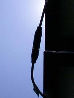
9 Proper Installation of Exterior Cables NEC (B)(4)(b) states how USE-2 is to be installed in exterior locations. PV Wire/Cable should follow the same installation methods as USE-2. Section refers the installer on to Article (NM Cable) for support methods Proper Installation of Exterior Cables Article Secured by staples, cable ties, straps, hangers, or similar fittings at intervals that do not exceed 4.5 feet 2. Secured within 12 inches of each box, cabinet, conduit body, or other termination 3. Sections protected from physical damage by raceway shall not be required to be secured within the raceway 4. Cable shall closely follow the surface of the building finish or of running boards ((NEC ) the analogous installation for USE- 2 in PV arrays is for the conductors to follow support rails or module extrusions) 5. Protected from physical damage by raceway when necessary Wire Management Proper Wire Management Room for Improvement Inspecting PV Systems for Code-Compliance 9

 6. Not following support members with conductors.")

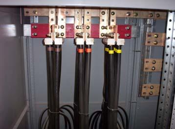
10 Wire Management Support? Common Installation Mistakes with Wire Management 1. Not enough supports to properly control cable. 2. Conductors touching roof or other abrasive surfaces exposing them to physical damage. 3. Conductors not supported within 12 inches of boxes or fittings. 4. Not supporting raceways at proper intervals. 5. Multiple cables entering a single conductor cable gland (aka cord grip) 6. Not following support members with conductors. Proper cable glands into Combiner Box Common Installation Mistakes with Wire Management cont. 7. Pulling cable ties too tight or leaving them too loose. 8. Not fully engaging plug connectors. 9. Bending conductors too close to connectors. 10. Bending USE-2 cable tighter than allowable bending radius. 11. Plug connectors on non-locking connectors not fully engaged Inspecting PV Systems for Code-Compliance 10


11 Wire Management Physical Damage Wire Management count the bad ideas Wire Management wire bending radius Wire Management plug engagement Inspecting PV Systems for Code-Compliance 11
 Module and Array Grounding Most common concern of field")


12 Wire Management Follow structural members & What the? What you can t see won t hurt you?? Inspection Checklist for Array: c) Module and Array Grounding Most common concern of field inspectors. Ungrounded module frames are a potential safety hazard. All array metal likely to become energized must be properly bonded together and grounded with lugs on each module and mounting rails or some equivalent equipment grounding method. Wrong connectors Module bonding and grounding methods 1. Some modules are designed to be grounded using a stainlesssteel thread-forming screw threaded into the module frame holding the EGC at a grounding symbol. An isolating washer, such as a stainless cup washer is often used to isolate the copper conductor from the aluminum frame to prevent galvanic corrosion. 2. Some modules can be grounded to their mounting structures with stainless steel star washers placed between the module and the support structure. This creates an electrical bond while isolating the aluminum frame from dissimilar materials such as galvanized steel. The EGC is attached to an electrically continuous support member with a properly installed grounding lug. Inspecting PV Systems for Code-Compliance 12


13 Module bonding and grounding methods cont. 3. Some modules can be grounded by properly installing a properly rated lay-in lug to the either the grounding point on the module, or any unused mounting hole. The EGC is run through this lay-in lug to bond the modules together. 4. For specific module mounting products (e.g. UniRac, ProSolar, DPW, etc ), there exists listed grounding clips to bond typical aluminum framed modules to the mounting structure. Only the proper clip can be used with each mounting structure. This allows the EGC to be connected to the electrically continuous rail. This method is consistent the NEC and NEC Some modules can be grounded together using serrated clips that hold the module to the support structure and electrically bond with the module. One lug on any module can ground a whole row. Early module and structure grounding improvements Identifying Grounding Clips Notice slight gap caused by properly installed clip. Inspecting PV Systems for Code-Compliance 13


 Improper Cad Tek screw used to hold lug Indoor lugs and Tek screws Aluminum bolted to steel")
14 Common Installation Mistakes with Module and Array Grounding 1. Not installing a grounding conductor on the array at all. 2. Using cad-plated Tek screws to fasten ground wires or lugs to modules. 3. Using indoor-rated grounding lugs on PV modules and support structures. 4. Not protecting EGCs smaller than 6 AWG from physical damage. 5. Allowing copper EGC to come in contact with the aluminum rails and module frames. 6. Assuming that simply bolting aluminum frames to support structures provides effective grounding. Nice Lugs! (poor fasteners) Improper Cad Tek screw used to hold lug Indoor lugs and Tek screws Aluminum bolted to steel without isolation washers and no effective bond Grounding Hardware and Components Indoor lug and Tek screw Stainless hardware looks like new Galvanized washer showing galvanic corrosion with aluminum contact Inspecting PV Systems for Code-Compliance 14

 or panel(s) secured by removable fasteners")


15 Inspection Checklist for Array: d) Electrical enclosures on Roof Accessible and Connections Suitable for the Environment Rooftop j-boxes in compliance with NEC Access to Boxes. Junction, pull, and outlet boxes located behind modules or panels shall be so installed that the wiring contained in them can be rendered accessible directly or by displacement of a module(s) or panel(s) secured by removable fasteners and connected by a flexible wiring system. Junction Boxes Connection between conductors in an outdoor location generally must be done within a rainproof junction box, NEMA 3R, or 4 (unless with approved connector) Waterproof wirenuts must be in j-boxes Improper Connections Wire twisted together, wrapped in tape, and in the sun Junction boxes are commonly used to transition conductors from exterior to conduit conductors and for combining array source circuits. Dry wirenut and not in a j-box Inspecting PV Systems for Code-Compliance 15


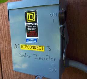
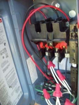
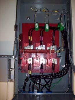
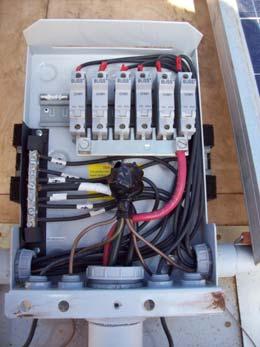
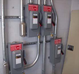
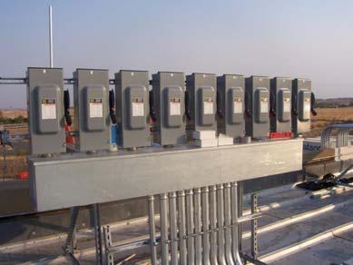
16 Ratings and locations of Disconnects Ratings and locations of Combiner Boxes NEMA 3R disconnect on sloped roof designed for vertical mounting only NEMA 4 Combiner Box with disconnect built-in. Designed for horizontal or vertical mounting Black cover to shield improperly installed switch only served to make switch invisible Common Installation Mistakes with Electrical Boxes, Conduit Bodies, and Disconnecting Means Many disconnects like these require the ungrounded conductor to be broken twice in series to get the 600Vdc rating 1. Installing disconnects rated for vertical installation in a nonvertical application. 2. Installing improperly rated fuses in source combiners and fused disconnects. 3. Covering boxes or conduit bodies making them nearly inaccessible for service. 4. Not following manufacturer s directions for wiring disconnect for 600 Vdc ratings. 5. Installing dry wire nuts in wet locations and inside boxes that get wet routinely. 6. Using improper fittings to bring conductors into exterior boxes. Incorrect Breaking of grounded conductor Correct Inspecting PV Systems for Code-Compliance 16


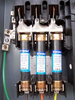
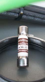
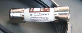
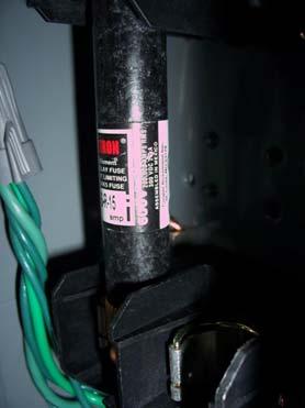

17 Correct Fuses Correct Fuses Correct Fuses?? Correct Fuses?? Inspecting PV Systems for Code-Compliance 17


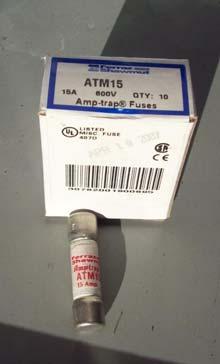
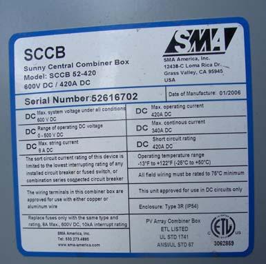
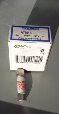
18 Correct Fuses and Terminals? Proper Current Rating? Proper Current Rating? Properly Rated Disconnects and Inverters Inspecting PV Systems for Code-Compliance 18


19 Inspection Checklist for Array: e) Array Fastened and Sealed According To Attachment Detail Proper and Improper Flashing Roof penetrations must be properly sealed to preclude leakage. Do a hand pull test on a sample of lag screw attachments to make sure they are secured to rafters. Look in attic to see if lags are visible. Common Installation Mistakes with Mounting Systems: 1. Not using supplied or specified hardware with the mounting systems. 2. Substituting Unistrut for special manufactured aluminum extrusions. 3. Not installing flashings properly. 4. Not using the correct roof adhesives for the specific type of roof. 5. Not attaching proper lag screws to roofing members. 6. Not drilling proper pilot holes for lag screws and missing or splitting roofing members. Inspection Checklist for Array: f) Conductor Ratings and Sizes Exposed Array Conductors The only singleconductor cables allowed in (B) are USE-2 and PV Wire (Cable). Conductors in raceways on rooftops Table (B)(2)(c) adds an additional 14 C-30 C to the ambient temperature. These high temperatures nearly always limit ampacity below the terminal temperature ampacity. Inspecting PV Systems for Code-Compliance 19
(2)(c) Common Installation Mistakes with Conductors: 1.")


20 Conduit Exposed to Sunlight Above Rooftops Table (B)(2)(c) Common Installation Mistakes with Conductors: 1. Not accounting for high operating temperatures in rooftop conduit. 2. Specifying THHN conductors rather than wet rated conductors in drawings where raceways are clearly located outdoors. 3. Specifying or installing THWN conductors in raceways that may exceed 60 C without properly correcting the THWN conductors for this temperature. Incorrect conductors and roof plumbing into combiner box Improperly Rated Conductors THWN conductors outside conduit Inspecting PV Systems for Code-Compliance 20


 Additional array")
] d) Attachment method according")

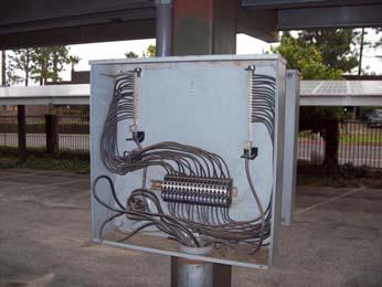
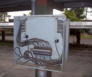
21 Section 2. Specifics For Ground-Mounted Arrays Support Structure and Attachment a) Foundation and mounting structure review b) Electrical bonding of structural elements c) Additional array electrode [690.47(D)] d) Attachment method according to plans e) Wiring not readily accessible Support Structure and Attachment Support Structure and Attachment Inspecting PV Systems for Code-Compliance 21


. 5.")

22 Wiring not readily accessible? Readily accessible or not? Common Installation Mistakes with Ground Mounting Systems: Section 3. Appropriate signs installed 1. Not using supplied or specified hardware with the mounting systems. 2. Substituting Unistrut for special manufactured aluminum extrusions. 3. No bonding of support structure or discontinuous grounding of support structure. 4. Dissimilar metals in contact with one another (e.g. aluminum and galvanized steel). 5. No bonding of aluminum structural elements to steel structural elements. 6. Array wiring readily accessible to other than authorized personnel. Sign construction Photovoltaic Power Source AC point of connection alternative power system Inspecting PV Systems for Code-Compliance 22


23 Sign Construction The NEC is not extremely specific about what signs should be made of. NEC states, The marking shall be of sufficient durability to withstand the environment involved. Electrical industry standards for outdoor signs is that signs should be metal or plastic with engraved or machine printed letters, or electro-photo plating, in a contrasting color to the sign background. Indoor signs may allow more variety of construction Photovoltaic Power Source Sign Signs and Labels Inspecting PV Systems for Code-Compliance 23


24 AC Point of Interconnection Signs and Labels it is possible to have too many. Section 4. Check that equipment ratings are consistent with application and signs Inverter Labels Inspecting PV Systems for Code-Compliance 24

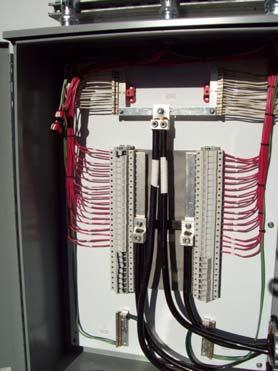
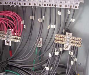
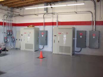
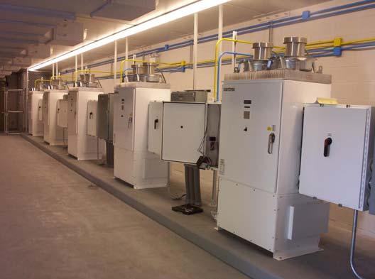
25 Disconnects consistent with requirements Guts show and tell Guts show and tell Guts show and tell Inspecting PV Systems for Code-Compliance 25

26 Guts show and tell Good Installation Practices Good Installation Practices Good Installation Practices Inspecting PV Systems for Code-Compliance 26
27 Good Installation Practices Nice Work Nice Work Nice Work Inspecting PV Systems for Code-Compliance 27
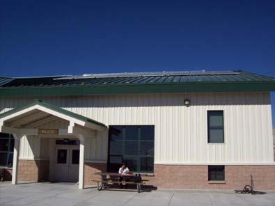

28 Nice Work Nice Work Nice Work Nice Work Inspecting PV Systems for Code-Compliance 28
PV System Permitting and Inspection. PV Codes and Standards Uniform Solar Energy Code
 PV System Permitting and Inspection Presented by Bill Brooks, PE Brooks Engineering PV Codes and Standards 101 What are the applicable codes and standards for PV systems? Electrical codes - NEC Article
Field Inspection Guideline for PV Systems
 Field Inspection Guideline for PV Systems Prepared for: Interstate Renewable Energy Council (available at www.irecusa.org) Brooks Engineering 873 Kells Circle Vacaville, CA 95688 www.brooksolar.com Prepared
Expedited Permit Process for PV Systems Micro-Inverter
 Micro-Inverter The Solar America Board for Codes and Standards (Solar ABCs) Expedited Permit Process provides a means to differentiate systems that can be permitted quickly and easily due to their similarity
Solar PV System Code Compliance Best Practices, 2017 NEC Updates, and Opportunities for Improvement
 Solar PV System Code Compliance Best Practices, 2017 NEC Updates, and Opportunities for Improvement MassCEC Webinar April 2017 Presented by: Matt Piantedosi Manager of Solar Field Operations The Cadmus
WITH THE TITLE 24. replacement. story. stories, etc. R disconnects. to, PV. unit and any. supporting frame. conditions. greater than the main
 CITY OF CYPRESS Building Division 5275 Orange Avenue, Cypress, California 906300 714-229-6730 buildingpermits@ @ci.cypress.ca.us RESIDENTIAL PHOTOVOLTAIC SYSEMS ALL WORK SHALL REQUIRE COMPLIANCE WITH THE
PV Codes and Standards 101
 BUILDING & INSPECTING CODE-COMPLIANT PV SYSTEMS Presented by Bill Brooks, PE Brooks Engineering Overview of Presentation PV System Basics Introduction to relevant Codes and Standards Summary of PV Electrical
Building Codes in Effect: 2010 California Building, Residential, Fire, Energy and Electrical Codes, including Article 690.
 AGUA CALIENTE BAND OF CAHUILLA INDIANS A SOVEREIGN TRIBAL GOVERNMENT Planning & Development Department Building and Safety Division 5401 Dinah Shore Drive Palm Springs, CA 92264 (760) 669-6800 RESIDENTIAL
Temporary Wiring Practices And Guidelines For NECA. National Electrical Contractors Association Omaha, Nebraska
 Temporary Wiring Practices And Guidelines For NECA National Electrical Contractors Association Omaha, Nebraska Table of Contents I. Planning II. Lighting and Power III. Maintenance IV. Inspections V. Routing
This product specification is written according to the Construction Specifications Institute MasterFormat, 2014 Update.
 Kaf-Tech Product Specification This product specification is written according to the Construction Specifications Institute MasterFormat, 2014 Update. SECTION 260519 METAL CLAD CABLE - MC-PLUS Neutral
PV Mounting System 2703 SERIES 200 UL GROUND MOUNT SYSTEM. SnapNrack Residential PV Mounting Systems Code Compliant Installation Manual
 PV Mounting System 2703 SERIES 200 UL GROUND MOUNT SYSTEM SnapNrack Residential PV Mounting Systems Code Compliant Installation Manual Series 200 UL Introduction Series 200 UL Introduction SnapNrack Series
Welcome to Douglas County PUD
 Welcome to Douglas County PUD We are committed to providing the best possible utility services at the lowest possible cost consistent with sound business principles. To better serve you, please fill out
CONSOLIDATED EDISON COMPANY OF NEW YORK, INC Van Dam Street Long Island City, NY ELECTRIC METER SHOP DEPARTMENT
 CONSOLIDATED EDISON COMPANY OF NEW YORK, INC. 48-05 Van Dam Street Long Island City, NY 11101 ELECTRIC METER SHOP DEPARTMENT METER ENGINEERING SPECIFICATION MES-350 REVISION 3 June 2016 EFFECTIVE DATE
2008 NEC Guide Lines for Home Owner Doing Electrical Work on their Property
 2008 NEC Guide Lines for Home Owner Doing Electrical Work on their Property A brief summary of the most used code references for residential wiring State of Idaho Division of Building Safety Electrical
Electrical Metallic Tubing (EMT) Fittings
 Fittings") Suggested Specifications for Electrical Metallic Tubing (EMT) Fittings Series 2 Insulated EMT Connector (Raintight) (Compression Type) Series 20 EMT Coupling (Raintight) (Compression Type) Series 0 Pipe
Suggested Specifications for Electrical Metallic Tubing (EMT) Fittings Series 2 Insulated EMT Connector (Raintight) (Compression Type) Series 20 EMT Coupling (Raintight) (Compression Type) Series 0 Pipe
SECTION (Master Template Final-05) ELECTRICAL BOXES. A. Provide boxes for electrical equipment and wiring devices as follows:
 ELECTRICAL BOXES. A. Provide boxes for electrical equipment and wiring devices as follows:") SECTION 16130 (Master Template Final-05) ELECTRICAL BOXES PART 1 GENERAL 1.01 SECTION INCLUDES A. Provide boxes for electrical equipment and wiring devices as follows: 1. Wall and ceiling outlet boxes.
SECTION 16130 (Master Template Final-05) ELECTRICAL BOXES PART 1 GENERAL 1.01 SECTION INCLUDES A. Provide boxes for electrical equipment and wiring devices as follows: 1. Wall and ceiling outlet boxes.
Specification Lightning Protection Systems
 Specification Lightning Protection Systems General: Summary A) This Section specifies the lightning protection system for the building(s) or structure(s). This system provides safety for the building and
Understanding Solar PV Permitting and Inspecting in New York State
 Understanding Solar PV Permitting and Inspecting in New York State Understanding Solar PV Permitting and Inspecting in New York State Prepared by: NY-Sun Team at the New York State Energy Research and
YINGLI SOLAR PV MODULES Installation and User Manual
 YINGLI SOLR PV MODULES Installation and User Manual Revision Date pr 19th, 2016 pplicable for IEC certified products This manual applies to photovoltaic modules ( PV modules, also commonly known as solar
WIRING METHODS CHAPTER 38
 CHAPTER 38 WIRING METHODS SECTION E3801 GENERAL REQUIREMENTS E3801.1 Scope. This chapter covers the wiring methods for services, feeders and branch circuits for electrical power and distribution. E3801.2
SECTION LOW-VOLTAGE ELECTRICAL POWER CONDUCTORS AND CABLES (24 Volt AC/DC or Less)
") SECTION 260523 LOW-VOLTAGE ELECTRICAL POWER CONDUCTORS AND CABLES (24 Volt AC/DC or Less) PART 1 - GENERAL 1.1 SUMMARY A. Related Documents: 1. Drawings and general provisions of the Subcontract apply
SECTION 260523 LOW-VOLTAGE ELECTRICAL POWER CONDUCTORS AND CABLES (24 Volt AC/DC or Less) PART 1 - GENERAL 1.1 SUMMARY A. Related Documents: 1. Drawings and general provisions of the Subcontract apply
BUSWAY LOW VOLTAGE (POW-R-WAY III) SECTION SECTION 16466
 SECTION SECTION 16466") BUSWAY LOW VOLTAGE (POW-R-WAY III) PART 1 GENERAL 1.01 1.02 SCOPE The Contractor shall furnish and install the busway system including all necessary fittings, hangers and accessories as specified herein
BUSWAY LOW VOLTAGE (POW-R-WAY III) PART 1 GENERAL 1.01 1.02 SCOPE The Contractor shall furnish and install the busway system including all necessary fittings, hangers and accessories as specified herein
UNDERGROUND SERVICES SECONDARY
 Reference UNDERGROUND SERVICES SECONDARY Underground services secondary... U- 1 General requirements for underground service... U- 2 Name of parts for underground service... U- 3 Conduit layouts... U-
ELECTRICAL BULLETIN
 PO Box 697 Halifax, Nova Scotia B3J 2T8 Labour and Advanced Education ELECTRICAL BULLETIN 2012-01 From: David MacLeod,C.E.I.,P.Eng. Pg 1 of 8 Provincial Chief Electrical Inspector Date : March 1, 2012
INSTALLATION INSTRUCTIONS FOR ELECTRICAL CONTRACTORS
 INSTALLATION INSTRUCTIONS FOR ELECTRICAL CONTRACTORS Rev. 1.5 1.10.13 Toll free (800) 288-6000 or www.hubbell-wiring.com P a g e 0 IMPORTANT SAFETY INSTRUCTIONS SAVE THESE INSTRUCTIONS WARNING- When using
Power Electronics, Inc. Packaged Equipment Center Standard Construction and Design Features
 DESIGN CRITERIA FOR STANDARD CONSTRUCTION: These standard design elements of the P.E.I. Power Equipment Center are utilized to meet the following design criteria per ASCE 7-05 as adopted by the IBC (International
SECTION INSULATED WIRE AND CABLE
 SECTION 16120 INSULATED WIRE AND CABLE PART 1 GENERAL 1.01 DESCRIPTION A. This section covers the contract item Insulated Wire and Cable, which includes the following items with accessories, and appurtenances:
APPLICATION FOR SOLAR PERMIT
 APPLICATION FOR SOLAR PERMIT Permit Application Application Checklist o New York State Unified Solar Permit Application for Roof Mounted Systems 12kW or less. (Includes Electrical Permit Application) o
NY State Unified Solar Permit
 PERMIT APPLICATION Town of Warwick Building Department (845) 986-1127 NY State Unified Solar Permit Unified solar permitting is available statewide for eligible solar photovoltaic (PV) installations. Municipal
rec Peak energy modules
 Installation manual rec Peak energy modules For installations according to UL 1703 Contents Table of figures 2 INTRODUCTION 3 How to use THIS MANual 3 YOUR RESPONSIBILITY as AN INSTALLER 3 SUPPORT 3 LIABILITY
Installation Guide EcoFoot5D High Density 5-Degree Ballasted Racking System Document No. ES10560
 Installation Guide Installation Guide EcoFoot5D High Density 5-Degree Ballasted Racking System Document No. ES10560 Rev 1.0, September 2017 Sales: 740-249-1877 Sales@EcolibriumSolar.com Field Support:
St. Clair County Electrical Code Regulations
 St. Clair County Electrical Code Regulations St. Clair County has adopted the 2011 National Electrical Code as amended with the following listed articles as the St. Clair County version of the National
B. Provide a complete conduit system with associated couplings, connectors, and fittings.
 SECTION 26 05 33 PART 1 - GENERAL 1.01 WORK INCLUDED A. Comply with the provisions of Sections 260500. B. Provide a complete conduit system with associated couplings, connectors, and fittings. 1.02 RELATED
SECTION CHAIN-LINK FENCES AND GATES 02821/1
 SECTION 02821 - CHAIN-LINK FENCES AND GATES 02821/1 PART 1 - GENERAL 1.1 SUMMARY A. This Section includes the following: 1. Chain-Link Fences: 2. Gates: horizontal slide or swing. 3. Fences installed where
1. Hangers and supports for electrical equipment and systems. 2. Construction requirements for concrete bases.
 SECTION 260529 - HANGERS AND SUPPORTS PART 1 - GENERAL 1.1 SUMMARY A. Section includes: 1. Hangers and supports for electrical equipment and systems. 2. Construction requirements for concrete bases. 1.2
GroundTrac. Installation Manual
 APPLICATION: The GroundTrac system is designed with a minimum amount of installed footings at greatly reduced labor. The system integrates with ordinary 1-1/2 schedule #40 galvanized water pipe. This ground
Service Entrance Cable Fittings
 Suggested Specifications for Service Entrance Fittings All service fittings shall be approved for the purpose by a nationally recognized testing laboratory, inspection agency or product evaluation organization.
2015 Code Rollout Meeting Q & A
 1 SECTION QUESTION SaskPower Inspections Dept. ANSWER 2 3 4 5 6 7 8 9 10 11 12 15-02-024 15-02-200 15-02-200 15-02-200 15-02-314 Are existing single or double 'weather proof when not in use' covers allowed
A. Product Data shall be provided for each type of product indicated.
 32 31 13 CHAIN LINK FENCES AND GATES SECTION 1 GENERAL 1.1 SUMMARY This Section includes the following: 1. Chain Link Fences 2. Gates for Chain Link Fences. See electrical specifications for electrical
Article 300: Wiring Methods And Materials
 Part E: Code Book Questions Article 300: Wiring Methods And Materials 1.! Conductors of A.C. or D.C. circuits rated 600 volt or less, shall be permitted to occupy the same! conduit if.! (a)!conductors
Specifications Electrical Metallic Tubing (EMT)
") T& Fittings Specifications Electrical Metallic Tubing (EMT) Ref. CEC Rule 12-000 not exceeding 750 Volts Electrical Metallic Tubing (EMT) is similar to rigid steel conduit but is much lighter, weighing
T& Fittings Specifications Electrical Metallic Tubing (EMT) Ref. CEC Rule 12-000 not exceeding 750 Volts Electrical Metallic Tubing (EMT) is similar to rigid steel conduit but is much lighter, weighing
Electric Service Requirements. Residential Overhead. Engineering Specification T002. February
 Electric Service Requirements Residential Overhead Engineering Specification T002 February 2017 0362-16 ENG. SPEC. T002 REV. 3 RESIDENTIAL OVERHEAD INSTALLATIONS page 1 of 12 Table of Contents 1 GENERAL
2003 International Residential Code ELECTRICAL PROVISIONS ONLY October 2005 EDITORIAL CHANGES SEVENTH PRINTING
 2003 International Residential Code ELECTRICAL PROVISIONS ONLY October 2005 EDITORIAL CHANGES SEVENTH PRINTING E3305.3: now reads The space equal to the width and depth of the panelboard and extending
FLORIDA PHOTOVOLTAIC BUILDINGS PROGRAM
 FLORIDA PHOTOVOLTAIC BUILDINGS PROGRAM Mounting Methods for Rooftop Photovoltaic Arrays Shingle, Tile, and Metal Roofing Systems Florida Solar Energy Center 1679 Clearlake Road Cocoa, Florida 32922 February
National Capital Region Recommendations for Residential Solar PV Systems
 National Capital Region Recommendations for Residential Solar PV Systems Fees 1. Create a flat residential solar PV permit fee based on the actual cost to administer Permitting 1. Require only one permit
SECTION GROUNDING AND BONDING
 SECTION 16060 PART 1 GENERAL 1.01 DESCRIPTION A. Section includes requirements for an electrical grounding system, including electrodes, grounding rods, connectors, insulators, equipment grounding and
moment Engineering + Design Warwick Avenue, Suite #C5 Fairfax, VA Phone: Web:
 CrossRail48SConnector RE: CrossRail48SConnectorEvaluation DesignReferenceDocuments MinimumDesignLoadsforBuildingsandOtherStructures 2010AluminumDesign MetalCurtainWallFasteners Overview Methods&DesignParameters
RESIDENTIAL SOLAR ENERGY SYSTEM APPLICATION
 City of Cerritos Department of Community Development Civic Center 18125 Bloomfield Avenue P.O. Box 3130 Cerritos, California 90703-3130 Phone: (562) 916-1201 Fax: (562) 916-1371 www.cerritosgis.com www.cerritos.us
NORTHWESTERN UNIVERSITY PROJECT NAME JOB # ISSUED: 03/29/2017
 SECTION 26 0526 - GROUNDING AND BONDING FOR ELECTRICAL SYSTEMS PART 1 - GENERAL 1.1 RELATED DOCUMENTS A. Drawings and general provisions of the Contract, including General and Supplementary Conditions
YINGLI SOLAR PANDA BIFACIAL MODULES Installation and User Manual
 YINGLI SOLAR PANDA BIFACIAL MODULES Installation and User Manual Revision date Jan. 15th, 2018 Applicable for IEC certified products The third edition This manual applies to photovoltaic PANDA BIFACIAL
(Condensed from National Electric Code)
") WIRING, SPECIFICATIONS, INSPECTION, AND METER INSTALLATION PROCEDURES FOR RESIDENTIAL CUSTOMERS SERVED BY SOUTHWEST ARKANSAS ELECTRIC COOPERATIVE CORPORATION Effective April 1, 1974 Revised February 3,
WIRING, SPECIFICATIONS, INSPECTION, AND METER INSTALLATION PROCEDURES FOR RESIDENTIAL CUSTOMERS SERVED BY SOUTHWEST ARKANSAS ELECTRIC COOPERATIVE CORPORATION Effective April 1, 1974 Revised February 3,
Revision 1 RAM ELEVATORS. Elevator Electrical Planning Guide. RAM Manufacturing Ltd
 RAM ELEVATORS Elevator Electrical Planning Guide This guide is intended for people with an understanding of electricity. If you are not, please consult a licensed electrician as errors in application of
2017 NEC Changes for Renewable Energy Systems Session one by Christopher LaForge
 2017 NEC Changes for Renewable Energy Systems Session one 2017 by Christopher LaForge Christopher LaForge IREC Certified Master Trainer NABCEP Certified Photovoltaic Installation Professional 30 years
ELECTRICAL BULLETIN
 PO Box 697 Halifax, Nova Scotia B3J 2T8 ELECTRICAL BULLETIN 2015-01 From: David MacLeod, C.E.I., P.Eng. Pg. 1 of 7 Provincial Chief Electrical Inspector Date: March 10, 2015 Subject: Adoption of the 2015
MECKLENBURG COUNTY. Land Use and Environmental Service Agency Code Enforcement 5/12/10 ELECTRICAL CONSISTENCY MEETING. Code Consistency Questions
 MECKLENBURG COUNTY Land Use and Environmental Service Agency Code Enforcement 5/12/10 ELECTRICAL CONSISTENCY MEETING Code Consistency Questions 1. Is it illegal to install a wet-niche luminaire face-up
MICRO-INVERTER PIGRID W MICRO GRID TIED INVERTER 208, 220, 230, 240VAC
 MICRO-INVERTER PIGRID250 250W MICRO GRID TIED INVERTER 208, 220, 230, 240V TECHNICAL MANUAL CONTENTS INTRODUCTION ------------------------------------------------------------------------------ 3 SAFETY
Electric Service Standards
 V: 1 of 6 A. Padmounted Requirements Complete requirements are contained in FPL specifications given to Customers for individual projects. Typical pad mounted transformer requirements include, but are
Basic Requirements for Residential Electrical Installations
 Basic Requirements for Residential Electrical Installations Wayne County Building Department 428 West Liberty Street Wooster, Ohio 44691 Phone: 330-287-5525 Fax: 330-287-5649 This brochure is intended
ELECTRIC METERING GENERAL
 1.0 INDEX 1.0 INDEX 2.0 SCOPE 3.0 GENERAL REQUIREMENTS 4.0 EQUIPMENT 5.0 METER REQUIREMENTS 6.0 METER FACILITIES 7.0 ELECTRICAL CONNECTIONS 2.0 SCOPE This guide covers general requirements and codes for
SECTION SLOPED TRANSLUCENT METAL SKYLIGHT SYSTEM
 PART 1- GENERAL 1.1 SUMMARY A. Section Includes: SECTION 084523 - SLOPED TRANSLUCENT METAL SKYLIGHT SYSTEM 1. Flat factory prefabricated structural insulated translucent sandwich panels; with glazed endwalls.
TEMPORARY METER POLE INSTALLATION
 TEMPARY METER POLE INSTALLATION MEMBER PROVIDED Location to be made by REMC within 50' of our transformer or existing service Temporary pole to be properly braced 24" 3 wire weatherhead (located 24" from
Specifications for Residential Overhead Electric Service Installation
 Specifications for Residential Overhead Electric Service Installation This brochure addresses most typical residential overhead service installations. Variances for the following specifications must be
4CS12 4CS-1/2 4X1-7/8D Handybox. Features. Dimensions and Weight. Long Description. Catalog Number
 3804 South Street 75964-7263, TX Nacogdoches Phone: 936-569-7941 Fax: 936-560-4685 AllenWatson@elliottelectric.com 4CS12 4CS-1/2 4X1-7/8D Handybox Appleton/Oz Gedney Catalog Number 4CS12 Manufacturer Appleton/Oz
PM200M00 PM245P00 PM250M01 PM300P00 PM318B00 PM318B01 PM096B00. Version 1.1
 BenQ Solar Photovoltaic Modules Installation Guide (IEC, ETL) PM200M00 PM245P00 PM250M01 PM300P00 PM318B00 PM318B01 PM096B00 Version 1.1 Note: The content of this manual is subject to change without notice.
DIVISION 1100 TRAFFIC
 SECTION 1102 STREET LIGHTING GENERAL INFORMATION The Idaho State Electrical Board has determined that all street lights are to be provided with an external fuse disconnect, in a junction box between the
Standard of Practice - Campus Electrical Distribution System
 A26.3 Standard of Practice - Campus Electrical Distribution System NOTE: Significant revisions or additions to the previous standards are highlighted in italics. GENERAL Designers shall verify that all
Proposals and Process 2017 National Electrical Code
 Proposals and Process 2017 National Electrical Code for Solar America Board for Codes and Standards Stakeholder Meeting; October 23, 2014 Ward Bower Ward Bower Innovations LLC Introduction The New NFPA
CONDUITS AND FITTINGS
 CONDUIT AND FITTINGS Rigid Steel Conduit 3801 Rigid PVC Conduit 3803 HDPE Conduit 3803 Flexible Non Metallic Liquid Tight Conduit Type LFNC-B 3804 PVC Coated Urethane Lined Galvanized Rigid Steel Conduit
SECTION SEISMIC CONTROL OSHPD
 SECTION 01451 PART 1 - GENERAL 1.01 DESCRIPTION A. Provide all required seismic restraints and calculations in order to insure that the installation of all architectural, mechanical, and electrical equipment/components
NOVABRIK MORTARLESS CONCRETE BRICK VENEER SPECIFICATION. MASTERFORMAT SECTION (Mortarless Concrete Brick Veneer)
") NOVABRIK MORTARLESS CONCRETE BRICK VENEER SPECIFICATION MASTERFORMAT SECTION 04818 (Mortarless Concrete Brick Veneer) Spec_USA_En_18102005.doc 12/1/2005 Novabrik Page 2 Section 04818 NOVABRIK MORTARLESS
NOVABRIK MORTARLESS CONCRETE BRICK VENEER SPECIFICATION MASTERFORMAT SECTION 04818 (Mortarless Concrete Brick Veneer) Spec_USA_En_18102005.doc 12/1/2005 Novabrik Page 2 Section 04818 NOVABRIK MORTARLESS
Effective June, Eaton-Durham Model # UTRS223ACH. Siemens, Model # SUAS877-PG. (or Landis & Gyr # UAS877-PG) Milbank. Model # U1980-O.
 Milbank. Model # U1980-O.") Siemens, Model # SUAS877-PG (or Landis & Gyr # UAS877-PG) Eaton-Durham Model # UTRS223ACH Milbank Midwest Model # U980-O UTRS223AMEP These are some examples of the single meter sockets we require for underground
Siemens, Model # SUAS877-PG (or Landis & Gyr # UAS877-PG) Eaton-Durham Model # UTRS223ACH Milbank Midwest Model # U980-O UTRS223AMEP These are some examples of the single meter sockets we require for underground
SECTION ACOUSTICAL PANEL CEILINGS
 SECTION 095113 ACOUSTICAL PANEL CEILINGS PART 1 - GENERAL 1.1 RELATED DOCUMENTS A. Drawings and General Provisions of the Contract, including General and Supplementary Conditions and Division 01 Specification
SEISMIC PROTECTION SYSTEMS Bracing Products for Racks & Cabinets
 SEISMIC PROTECTION SYSTEMS Bracing Products for Racks & Cabinets Seismic Frame Two-Post Rack Page 11-3 Seismic Protection Products - Racks Page 11-6 Seismic Protection Products - Runway Page 11-8 Seismic
CHAPTER 11 CONDUITS AND FITTINGS
 CONDUITS AND FITTINGS CHAPTER 11 CONDUITS AND FITTINGS The standards and requirements for conduits and fittings used for traffic control signal and lighting systems are presented in this chapter. 11.1
Title: YALE OFFICE OF FACILITIES PROCEDURE MANUAL Chapter: 01 - Yale Design Standard Division: Electrical Standards
 Change History Date Description of Change Pages / Sections Modified Change Approver Initials 6/15/16 Updated division section from 16124 to 2605 - mgl44 13, removed references to other section 10/17/14
B. Insulated Conductors: Stranded copper wire, green or green with yellow stripe insulation, insulated for 600 V, and complying with UL 83.
 SECTION 270526 - GROUNDING AND BONDING FOR COMMUNICATIONS SYSTEMS PART 1 - GENERAL 1.1 SUMMARY A. Section Includes: 1. Grounding conductors. 2. Grounding connectors. 3. Grounding busbars. 4. Grounding
Town of Wilton Building Department
 Town of Wilton Building Department Permitting hours 7:30-12:00 (unless otherwise posted) Tel: 203-563-0177 REQUIREMENTS FOR A SOLAR PHOTOVOLTAIC PERMIT Completed and signed Minor Solar Permit Application
PORT OF SAN FRANCISCO ELECTRICAL CODE. Based on the 2016 California Electrical Code
 2016 PORT OF SAN FRANCISCO ELECTRICAL CODE Based on the 2016 California Electrical Code The complete 2016 Port of San Francisco Electrical Code adopts and amends the 2013 edition of the California Electrical
Large Basic Service. This Section applies to members requiring new. Introduction. Service Types
 Large Basic Service Introduction This Section applies to members requiring new Large Basic electric service installations, greater than 400 amps single phase and greater than 50kW three phase. This Section
Installation manual. rec TwinPeak SERIEs. For the installation of REC TwinPeak Series solar panels certified according to IEC / 61730
 Installation manual rec TwinPeak SERIEs For the installation of REC TwinPeak Series solar panels certified according to IEC 61215 / 61730 Contents Contents 2 Table of figures 2 INTRODUCTION 3 How to use
A. All materials shall be tested and listed by an OSHA approved Nationally Recognized Testing Laboratory (NRTL).
.") 16450 GROUNDING ************************************************************************************************************* SPECIFIER: CSI MasterFormat 2004 number: 26 05 26 An optional keynote to the
16450 GROUNDING ************************************************************************************************************* SPECIFIER: CSI MasterFormat 2004 number: 26 05 26 An optional keynote to the
Installation Instructions Self-Regulating (sr) roof and gutter
 roof and gutter") Installation Instructions Self-Regulating (sr) roof and gutter De-icing Cables Industrial and Commercial Series Contents page Section 1. Overview 1.1 Precautions... 2 1.2 Cable and components... 2 1.3
Installation Instructions Self-Regulating (sr) roof and gutter De-icing Cables Industrial and Commercial Series Contents page Section 1. Overview 1.1 Precautions... 2 1.2 Cable and components... 2 1.3
UNIFIED FACILITIES GUIDE SPECIFICATIONS
 USACE / NAVFAC / AFCEC / NASA UFGS-26 27 29 (April 2006) Change 1-08/13 -------------------------- Preparing Activity: NAVFAC Replacing without change UFGS-16407 (August 2004) UNIFIED FACILITIES GUIDE
Nuheat WEATHER-READY ROOF & GUTTER DE - ICING SYSTEM. 13mm Self-Regulating Heating Cable. UV Resistant Polyolefin Outer Jacket
 Nuheat WEATHER-READY ROOF & GUTTER DE - ICING SYSTEM 13mm Self-Regulating Heating Cable UV Resistant Polyolefin Outer Jacket Tinned Copper Braid Polyolefin Inner Jacket Fire Resistant Conductive Core 16
Shur-Shot X-Proof Hydrogen Fluoride Alarm Operations Manual
 Shur-Shot X-Proof Hydrogen Fluoride Alarm Operations Manual P/N 1000006053 Rev E $7%$QDO\WLFV// //& 733 Dairy Rd. Parkton, Md. 21120 www.atbanalytics.com (410) 733-6365 Table of Contents Chapter 1: Getting
The Canadian Electrical Code (Saskatchewan Amendments) Regulations, 1999
 Regulations, 1999") CANADIAN ELECTRICAL CODE 1 The Canadian Electrical Code (Saskatchewan Amendments) Regulations, 1999 Repealed by Chapter E-6.3 Reg 8 (effective June 24, 2003). Formerly Chapter E-6.3 Reg 6 (effective March
CANADIAN ELECTRICAL CODE 1 The Canadian Electrical Code (Saskatchewan Amendments) Regulations, 1999 Repealed by Chapter E-6.3 Reg 8 (effective June 24, 2003). Formerly Chapter E-6.3 Reg 6 (effective March
Originally Issued: 03/13/2015 Revised: 03/10/2017 Valid Through: 03/31/ Description
 EVALUATION SUBJECT: TILE FLASHING SYSTEM REPORT HOLDER: EcoFasten Solar 4741 W. Polk Street, Ste. 4 Phoenix, AZ 85043 Phone: 888-766-4273 brian@alpinesnowguards.com CSI DIVISION: 06 WOOD AND PLASTICS CSI
APPENDIX. WOOD JOIST/RAFTER MAXIMUM SPANS ( for 16 o.c. spacing) WITH SINGLE ROW OF PV PANELS AT MIDSPAN (ft.) AND PANEL SUPPORT AT 32 o.c.
 WITH SINGLE ROW OF PV PANELS AT MIDSPAN (ft.) AND PANEL SUPPORT AT 32 o.c.") 1 Span Tables The following Wood Joist/Rafter Maximum Span Tables can be used to determine the adequacy of an existing wood framed roof structure to support the additional dead load created by PV panel
1 Span Tables The following Wood Joist/Rafter Maximum Span Tables can be used to determine the adequacy of an existing wood framed roof structure to support the additional dead load created by PV panel
Revisions for the 2011 National Electrical Code - Part 2
 PDHonline Course E356 (3 PDH) Revisions for the 2011 National Electrical Code - Part 2 Instructor: Patrick Ouillette 2012 PDH Online PDH Center 5272 Meadow Estates Drive Fairfax, VA 22030-6658 Phone &
ROOF MOUNT KIT OWNERS MANUAL
 ROOF MOUNT KIT OWNERS MANUAL Made in the USA by: Primus Wind Power, Inc. 938 Quail St. Lakewood, CO 80215 Phone: (303) 242-5820 www.primuswindpower.com AIR is a trademark of Primus Wind Power, Inc. ROOF
PHYSICAL FACILITIES Consultant s Handbook Division 27 COMMUNICATIONS 0000 COMMUNICATIONS
 1 Introduction 1.1 In the design of Telecommunications systems in Purdue facilities, the overall consideration should be to understand and treat telecom as a utility. It should be assumed that all new
Originally Issued: 04/15/2011 Revised: 04/05/2018 Valid Through: 04/30/ Materials
 EVALUATION SUBJECT: GREENFASTEN-1-812 AND COMPSLIDE ROOF MOUNT ASSEMBLIES REPORT HOLDER: EcoFasten Solar 4741 W. Polk St., Ste. 4 Phoenix, AZ 85043 (877) 589-3947 brian@ecofastensolar.com CSI DIVISION:
15 kv EPR Insulated, Jacketed, URD Cable
 15 kv EPR Insulated, Jacketed, URD Cable 1000 kcm Copper Conductor with Tape Shield Page 1 of 11 Table Of Contents 1 GENERAL... 3 2 STANDARDS... 3 3 APPROVED CABLE MANUFACTURERS... 3 4 REEL SPECIFICATIONS...
Safety Considerations for Photovoltaic Systems
 Pennsylvania Building Officials Conference & Pennsylvania Fire Code Officials State College, PA September 18, 2015 Safety Considerations for Photovoltaic Systems Ron Celentano of Celentano Energy Services
PIP PCEPA003 Process Analyzer System Field Installation Guidelines
 January 2016 Process Control PIP PCEPA003 Process Analyzer System Field Installation Guidelines PURPOSE AND USE OF PROCESS INDUSTRY PRACTICES In an effort to minimize the cost of process industry facilities,
HIGH MAST CAMERA POLE ASSEMBLY GENERAL
 10-3.24 HIGH MAST CAMERA POLE ASSEMBLY GENERAL The Contractor must furnish and install the following equipment for high mast camera pole assembly as described herein and as shown on the plans: 1. Camera
Ballasted Roof Mounting Installation Manual
 Ballasted Roof Mounting Installation Manual www.ironridge.com 800-227-9523 Rev C, July 2012 This manual s part #: BRM-MAN-IM Copyright 2012 IronRidge, Inc. All rights reserved. 2 Ballasted Roof Mounting
Thank you for purchasing the SC-CONVERSION System 500/600 Conversion Kit. This Kit is available in two different versions:
 Rev. 1 (Jun 30, 2016) Thank you for purchasing the SC-CONVERSION System 500/600 Conversion Kit. This Kit is available in two different versions: Part # 4K01328-FI SC-CONVERSION Conversion Kit with MEI
ELECTRICAL CODE TRADE REFERENCE
 ELECTRICAL CODE TRADE REFERENCE FIFTH EDITION By Marvin Rosenberg UNIT 2: CODE COMPONENTS General Rule Sections 0 Definitions accurate interpretation 2 General Rules administrative and technical requirements
Panel 7 Proposals For 2005 NEC Articles 320, 322, 324, 326, 328, 330, 332, 334, 336, 338, 340, 382, 394, 396 and 398
 Panel 7 Proposals For 2005 NEC Articles 320, 322, 324, 326, 328, 330, 332, 334, 336, 338, 340, 382, 394, 396 and 398 The National Electrical Code Technical Correlating Committee Identified concerns with
SolarStyl BIPV New Building Integrated Photovoltaic System August V13 Page 0
 SolarStyl BIPV New Building Integrated Photovoltaic System 2010 August V13 Page 0 By ArcelorMittal Stainless & Nickel Alloys SolarStyl Frame for BIPV Systems To simplify photovoltaic roof and facade design.