Panduit Corporation Tinley Park, Illinois. Outset and Inset Cabinets Seismic Load Rating and Anchorage Design
|
|
|
- Anthony Francis
- 6 years ago
- Views:
Transcription

1 Panduit Corporation Tinley Park, Illinois Outset and Inset Cabinets Seismic Load Rating and Anchorage Design February 13, 2013 Degenkolb Job Number B Degenkolb Engineers SUITE 235 Montgomery Street San Francisco, California phone fax
2 Signature Page Signature Page The seismic load rating analysis and anchorage design of the Panduit Outset and Inset Cabinets was performed in accordance with ASCE 7-05 Minimum Design Loads for Buildings and Other Structures. Respectfully submitted, Adrian M. Nacamuli, S.E Associate Principal Degenkolb Engineers Degenkolb Engineers i Seismic Load Rating and Anchorage Design
3 Table of Contents Table of Contents Signature Page... i Table of Contents... ii List of Figures... iii List of Tables... iv 1.0 Introduction Seismic Demands Cabinet Descriptions Outset Cabinets Inset (Switch) Cabinet Seismic Load Rating Analysis Summary of Outset Cabinet Seismic Evaluation Summary of Inset Cabinet Seismic Evaluation Seismic Anchorage Design Analysis & Results Outset Cabinets Anchorage Design Inset Cabinets Anchorage Design Appendix A Seismic Anchorage Drawings Degenkolb Engineers ii Seismic Load Rating and Anchorage Design
4 List of Figures List of Figures Figure 1 Outset Cabinets... 3 Figure 2 Vertical Cabinet Post Connections... 4 Figure 3 Inset Cabinet... 5 Figure 4 Vertical Cabinet Post Connections... 6 Figure 5 3D Perspective View of Analysis Model... 8 Figure 6 3D Perspective View of Analysis Model Degenkolb Engineers iii Seismic Load Rating and Anchorage Design
5 List of Tables List of Tables Table 1 Outset Cabinet Anchorage: Case 3 Usage Guidelines Table 2 Outset Cabinet Anchorage: Case 2 Usage Guidelines Table 3 Inset Cabinet Anchorage: Case 3 Usage Guidelines Table 4 Inset Cabinet Anchorage: Case 2 Usage Guidelines Degenkolb Engineers iv Seismic Load Rating and Anchorage Design
6 1.0 Introduction 1.0 Introduction This report summarizes the seismic load rating analysis and seismic anchorage design for the Panduit outset and inset (switch) cabinets. The seismic load rating analysis and the seismic anchorage design were both conducted based on the 2009 International Building Code, which references the American Society of Civil Engineers Standard 7-05, Minimum Design Loads for Buildings and Other Structures. ASCE 7-05 is the primary standard for designing buildings and for designing nonstructural components and their anchorages within buildings. ASCE 7-05 references other national standards for the design of hot rolled steel (AISC), cold formed steel (AISI) and concrete (ACI) elements and have been used accordingly. The outset cabinet is a four post frame which comes in depths of 1070 and 1200 millimeters and widths of 600, 700, and 800 millimeters with a maximum height of 2150 millimeters. The inset or switch frame is a four post cabinet which comes in depths of 1070 and 1200 millimeters with a width of 800 millimeters and a height of 2150 millimeters. The cabinets were analyzed to determine the seismic load rating of each unit based on the maximum design-level acceleration found in California. SAP2000 was used to model each cabinet using static loads distributed along the frame. Seismic anchorage of the cabinets to a concrete slab has been designed for three basic cases: Rack located on a concrete slab on grade and anchored with expansion anchors. Rack located on an elevated concrete slab and anchored with expansion anchors. Rack located on an elevated concrete slab and anchored with through-bolts. Additionally, details have been provided for the condition where the unit rests on a raised access floor. Degenkolb Engineers 1 Seismic Load Rating and Anchorage Design
7 2.0 Seismic Demands 2.0 Seismic Demands The seismic demands were calculated based on ASCE 7-05 Minimum Design Loads for Buildings and Other Structures. Since there is no specific location where this cabinet will be used, the ground motion parameters selected correspond to the location with the highest demand in California. As specified in the code when the soil properties are unknown, Site Class D was assumed. Therefore, the calculated design-level spectral acceleration, S DS, is Compared to most typical locations in California, this value is relatively high, a point which will be addressed later in this report. Furthermore, the cabinet was assumed to be installed at the roof level of the building where seismic forces are highest. Allowances were made later in the analysis summary to account for cabinets installed in lower floors of the structure. Seismic demands for anchorage and lateral load rating were calculated using equation of ASCE 7-05: Where a p accounts for the dynamic properties of the cabinet, S DS is the ground shaking intensity, Wp is the component weight, Rp accounts for the ability of the component to dissipate energy under seismic loading, Ip is an importance factor taken as 1.0 and z represents the height within the building that the component is installed at and h represents the overall building height. Based on cabinet deflection information provided from Panduit and our own dynamic analysis, it was determined that the cabinet has a fundamental period greater than 0.06 seconds. Therefore, according to the definition provided by ASCE 7-05, the cabinet was analyzed as a flexible component and an amplification factor, a p, of 2.5 was used in calculating the seismic design force. A response modification factor, R p, of 3.5 was used to account for the ductility of the cabinet itself. The ratio of z/h was taken as 1.0, which yields the highest lateral force. Degenkolb Engineers 2 Seismic Load Rating and Anchorage Design


 (b) (c) Figure 1 Outset Cabinets (a) 600x1070x45RU; (b) 800x1070x45RU; (c) 600x1200x45RU The top and bottom of the cabinet consists of welded")
8 3.0 Cabinet Descriptions 3.0 Cabinet Descriptions 3.1 Outset Cabinets The outset cabinets have a four post frame that is 1070 or 1200 millimeters deep by 600, 700, or 800 millimeters wide with a maximum height of 2150 millimeters. Cabinet self-weight was assumed to be 300 pounds and maximum static load was assumed to be 3,000 pounds. Figure 1 shows three different configurations of the outset cabinets. (a) (b) (c) Figure 1 Outset Cabinets (a) 600x1070x45RU; (b) 800x1070x45RU; (c) 600x1200x45RU The top and bottom of the cabinet consists of welded assemblies. The vertical posts are connected directly to each assembly using two M6 hex head bolts and through the fascia using two M5 torx screws. The strength of these connections, shown below in Figure 2, will be considered in the lateral load rating analysis. Degenkolb Engineers 3 Seismic Load Rating and Anchorage Design
9 3.0 Cabinet Descriptions (a) (b) Figure 2 Vertical Cabinet Post Connections (a) Post to frame rivet weldment; (b) Fascia to frame rivet weldment and post Degenkolb Engineers 4 Seismic Load Rating and Anchorage Design
10 3.0 Cabinet Descriptions 3.2 Inset (Switch) Cabinet The inset cabinet is a four post frame that is 1070 or 1200 millimeters deep by 800 millimeters wide with a maximum height of 2150 millimeters. Cabinet self-weight was assumed to be 300 pounds and maximum static load was assumed to be 3,000 pounds. Figure 3 shows the configuration of the inset cabinet. Figure 3 Inset Cabinet The top and bottom of the cabinet consist of welded assemblies. The vertical posts are connected to brackets using five 3/8-inch diameter huckbolts. The brackets are welded to the top and bottom assemblies on all four sides. Connection details are shown in Figure 4. The strength of these connections will be considered in the lateral load rating analysis. Degenkolb Engineers 5 Seismic Load Rating and Anchorage Design
11 3.0 Cabinet Descriptions (a) Figure 4 Vertical Cabinet Post Connections (a) Bracket to weldment; (b) Post to bracket (b) Degenkolb Engineers 6 Seismic Load Rating and Anchorage Design
12 4.0 Seismic Load Rating Analysis 4.0 Seismic Load Rating Analysis 4.1 Summary of Outset Cabinet Seismic Evaluation The Panduit 600x1070x45RU Outset Cabinet Frame was analyzed to determine the maximum seismic load rating of the unit as this is the critical cabinet size with respect to lateral load capacity. Demands were calculated using the maximum design-level spectral acceleration, S DS, found in California and by assuming that the cabinet is installed at the roof level of the building where the forces are highest. The seismic load was applied as a static load distributed over each of the vertical frame posts. SAP2000 was used to model the frame and calculate the maximum moment in each post, shown below in Figure 5. Detailed calculations of the lateral load capacity can be found in Appendix A. The maximum lateral load that the cabinet can withstand is a total of 520 lb distributed evenly among the four posts. Given the maximum value of S DS in California, S DS = 1.93, the seismic demand on the unit at various levels in the structure is: Roof-Height: 1.65 x Weight Mid-Height: 1.10 x Weight Ground Level: 0.58 x Weight Therefore, using the values above, we can scale the weight of the cabinet based on its height within the structure. The maximum weight of the cabinet and contents for a given level is: Roof-Height: Mid-Height: Ground Level: 315 lb 473 lb 900 lb The S DS value initially used for this analysis is the maximum found in the entire state of California and corresponds to a specific location. A more common value in California for a nonnear-fault site is S DS = Using this value, we can scale down the demands and thus increase the maximum weight of the cabinet. Based on these scaled values, the maximum weight of the cabinet and contents for a given level is: Roof-Height: Mid-Height: Ground Level: 609 lb 913 lb 1737 lb The seismic capacities shown here are limited by the strength of the connection between the vertical frame posts and the frame rivet weldment. Degenkolb Engineers 7 Seismic Load Rating and Anchorage Design
13 4.0 Seismic Load Rating Analysis (a) (b) Figure 5 3D Perspective View of Analysis Model (a) Loading in global X direction; (b) Loading in global Y direction Degenkolb Engineers 8 Seismic Load Rating and Anchorage Design
14 4.0 Seismic Load Rating Analysis 4.2 Summary of Inset Cabinet Seismic Evaluation The Panduit 800x1070x45RU Switch Frame was analyzed to determine the maximum seismic load rating of the unit. Demands were calculated using the maximum design-level spectral acceleration, S DS, found in California and by assuming that the cabinet is installed at the roof level of the building where the forces are highest. The seismic load was applied as a static load distributed over each of the vertical frame posts. SAP2000 was used to model the frame and calculate the maximum moment in each post, as shown below in Figure 6. Detailed calculations of the lateral load capacity can be found in Appendix A. The maximum lateral load that the cabinet can withstand is a total of 910 lb distributed evenly among the four posts. Given the maximum value of S DS in California, S DS = 1.93, the seismic demand on the unit at various levels in the structure is: Roof-Height: 1.65 x Weight Mid-Height: 1.10 x Weight Ground Level: 0.58 x Weight Therefore, using the values above, we can scale the weight of the cabinet based on its height within the structure. The maximum weight of the cabinet and contents for a given level is: Roof-Height: Mid-Height: Ground Level: 551 lb 827 lb 1574 lb The S DS value initially used for this analysis is the maximum found in the entire state of California and corresponds to a specific location. A more common value in California for a nonnear-fault site is S DS = Using this value, we can scale down the demands and thus increase the maximum weight of the cabinet. Based on these scaled values, the maximum weight of the cabinet and contents for a given level is: Roof-Height: Mid-Height: Ground Level: 1064 lb 1596 lb 3038 lb The seismic capacities shown here are limited by the bending strength of the frame posts about their weak axis. Degenkolb Engineers 9 Seismic Load Rating and Anchorage Design
15 4.0 Seismic Load Rating Analysis (a) (b) Figure 6 3D Perspective View of Analysis Model (a) Loading in global X direction; (b) Loading in global Y direction Degenkolb Engineers 10 Seismic Load Rating and Anchorage Design
16 5.0 Seismic Anchorage Design 5.0 Seismic Anchorage Design Seismic anchorage of the cabinets to a concrete slab has been designed for three cases: 1. Rack located on a concrete slab on grade and anchored with Hilti expansion anchors. 2. Rack located on an elevated concrete slab and anchored with Hilti expansion anchors. 3. Rack located on an elevated concrete slab and anchored with through-bolts. In Addition, details have been provided for the condition where the unit rests on a raised access floor. This detail consists of using the anchorage design developed for the above cases to bolt the rack to the access floor and extending the anchor bolts down to expansion anchors fastened to the concrete slab. Detailed drawings of the anchorage designs can be found in Appendix D. 5.1 Analysis & Results Anchorage analysis was completed in accordance with Chapter 13 of ASCE7-05. Anchorage geometry was used to determine the critical load angle (the worst case direction of horizontal loading for the unit). The resultant tension and shear loads and locations were then determined and entered into Hilti Profis to determine the required anchor size and embedment. Typical concrete strength (3,000 psi) and thicknesses were used to develop the most universal solutions. Anchorage designs for outset and inset cabinets can be found in sections and 5.1.3, respectively. In addition to anchorage design, the seismic angle and connecting bolts were designed for the seismic loads. Angle bending governed the required angle thickness and bolt shear governed the size of the bolts connecting the angle to the unit. For all cases, an L4x4x1/4 angle and three (3) M10 Grade 8.8 bolts are adequate for the seismic demands. Please note that the required angle has longer legs and a larger thickness than the standard shipping angle provided by Panduit. Detailed calculations for the design of the seismic anchorages can be found in Appendices B and C Outset Cabinets Anchorage Design Based on our calculations, we have determined that anchorage to a slab-on-grade (Case 1) can be designed to resist the maximum seismic demand for anywhere in California with the partially loaded rack weight of 3,000 pounds. Table 2 outlines usage guidelines for case 1. Anchorage to an elevated concrete slab with thru-bolts (Case 3) can be designed to resist the seismic demand in most locations in California with the fully loaded rack weight. The load carrying capacity of case 3 is limited by bending of the seismic angle attachment at the throughbolt locations. Table 1 provides usage guidelines for case 3. Degenkolb Engineers 11 Seismic Load Rating and Anchorage Design
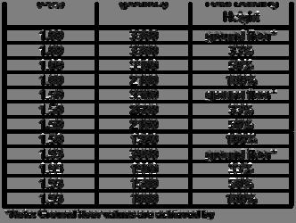
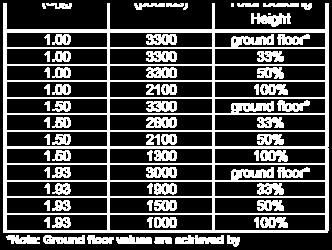
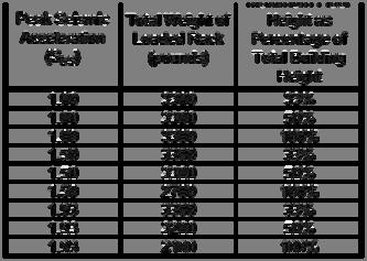
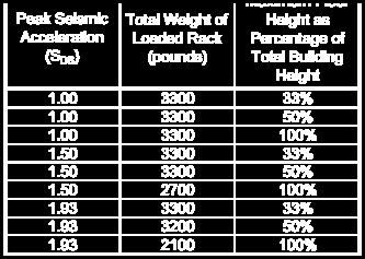
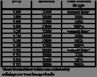
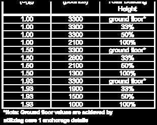
17 5.0 Seismic Anchorage Design Table 1 Outset Cabinet Anchorage: Case 3 Usage Guidelines Peak Seismic Acceleration (S DS ) Total Weight of Loaded Rack (pounds) Maximum Floor Height as Percentage of Total Building Height % % % % % % % % % Anchorage to an elevated concrete slab with expansion anchors (Case 2) has a lower lateral load resisting capacity than Case 3 due to the failure of the expansion anchors in the concrete fill on metal deck. As a result, Case 2 has the most significant limitations on how it can be used. Table 2 summarizes scenarios where Case 2 applies for outset cabinets. Table 2 Outset Cabinet Anchorage: Case 2 Usage Guidelines Peak Seismic Acceleration (S DS ) Total Weight of Loaded Rack (pounds) Maximum Floor Height as Percentage of Total Building Height ground floor* % % % ground floor* % % % ground floor* % % % *Note: Ground floor values are achieved by utilizing case 1 anchorage details Degenkolb Engineers 12 Seismic Load Rating and Anchorage Design
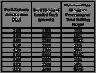
18 5.0 Seismic Anchorage Design Note that a thicker concrete fill (6 inches or greater) would provide a greater selection of anchor sizes and embedment depths resulting in additional situations where Case 2 can be utilized. Thicker concrete fills are typically found in applications where the servers encompass a large floor area. A Structural Engineer would be required to determine the load rating for these specialized conditions Inset Cabinets Anchorage Design Based on our calculations, we have determined that anchorage to a concrete slab-on-grade (Case 1) can be designed to resist the maximum seismic demand for anywhere in California with the fully loaded rack weight of 3,300 pounds. Anchorage to an elevated concrete slab with thru-bolts (Case 3) can be designed to resist the seismic demand in most locations in California with the fully loaded rack weight. The load carrying capacity of Case 3 is limited by bending of the seismic angle attachment at the thru-bolt locations. Table 3 provides usage guidelines for Case 3. Table 3 Inset Cabinet Anchorage: Case 3 Usage Guidelines Peak Seismic Acceleration (S DS ) Total Weight of Loaded Rack (pounds) Maximum Floor Height as Percentage of Total Building Height % % % % % % % % % Degenkolb Engineers 13 Seismic Load Rating and Anchorage Design
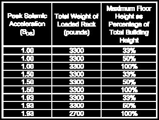
19 5.0 Seismic Anchorage Design Anchorage to an elevated concrete slab with expansion anchors (Case 2) has a lower lateral load resisting capacity than Case 3 due to the failure of the expansion anchors in the concrete fill on metal deck. As a result, case 2 has the most significant limitations on how it can be used. Table 4 summarizes scenarios where Case 2 applies for inset cabinets. Table 4 Inset Cabinet Anchorage: Case 2 Usage Guidelines Peak Seismic Acceleration (S DS ) Total Weight of Loaded Rack (pounds) Maximum Floor Height as Percentage of Total Building Height ground floor* % % % ground floor* % % % ground floor* % % % *Note: Ground floor values are achieved by utilizing case 1 anchorage details Note that a thicker concrete fill (6 inches or greater) would provide a greater selection of anchor sizes and embedment depths resulting in additional situations where Case 2 can be utilized. Thicker concrete fills are typically found in applications where the servers encompass a large floor area. A Structural Engineer would be required to determine the load rating for these specialized conditions. Degenkolb Engineers 14 Seismic Load Rating and Anchorage Design
20 Appendix A Seismic Anchorage Drawings Appendix A Seismic Anchorage Drawings Degenkolb Engineers 15 Seismic Load Rating and Anchorage Design
21
22
23
24
25
26
27
28
29
30
31
32
AC R1 # Triangle Parkway Suite 100 Norcross, Ga Phone: Fax: AC R1. September 11, 2012
 AC70-1012-R1 #12 AC70-1012-R1 #12 AC70-1012-R1 September 11, 2012 Mr. Brian Gerber Ms. Elyse Levy International Code Council Evaluation Service (ICC ES) 5360 Workman Mill Road Whittier, CA 90601 2256 RE:
Originally Issued: 03/08/2013 Revised: 03/14/2017 Valid Through: 03/31/2019
 EVALUATION SUBJECT: ALUR DIVIDING WALL REPORT HOLDER: Modular Architectural Interiors LLC dba MAI 330 Waterloo Valley Road Mount Olive, NJ 07828 Phone: (973) 446-2300 Fax: (973) 446-2399 www.maispace.com
Design Example 2 Reinforced Concrete Wall with Coupling Beams
 Design Example 2 Reinforced Concrete Wall with Coupling Beams OVERVIEW The structure in this design example is a six story office building with reinforced concrete walls as its seismic force resisting
Trusted SECTION: 04 HILTI, INC. TULSA, Conformity! ICC-ES Evaluation. not specifically. Copyright 2015
 0 ICC ES Report ICC ES (800) 42 6587 (562) 699 054 www.icc es.orgg 000 Most Widely Accepted and Trusted ESR 2269 Reissued 02/205 This report is subject to renewal 02/207. DIVISION: 0 00 00 CONCRETE SECTION:
REPORT HOLDER: HILTI, INC DALLAS PARKWAY, SUITE 1000 PLANO, TEXAS EVALUATION SUBJECT:
 0 Most Widely Accepted and Trusted ICC ES Evaluation Report ICC ES 000 (800) 423 6587 (562) 699 0543 www.icc es.org ESR 2269 Reissued 02/2017 This report is subject to renewal 02/2019. DIVISION: 03 00
SECTION SEISMIC RESTRAINT REQUIREMENTS FOR NON-STRUCTURAL COMPONENTS REVISED PART 1 GENERAL 1.1 DESCRIPTION:
 SECTION 13 05 41 SEISMIC RESTRAINT REQUIREMENTS FOR NON-STRUCTURAL COMPONENTS REVISED 1-25-13 PART 1 GENERAL 1.1 DESCRIPTION: A. Provide seismic restraint in accordance with the requirements of this section
Copyright. magazine. CFS Load Bearing Construction
 Progressive Collapse Requirements Cold-Formed Steel Load Bearing Construction By Nabil A. Rahman, Ph.D., P.E., Michael Booth and Gary Bennett Figure 1: Cold formed steel load bearing mid-rise construction.
Seismic Restraints. Cent-R-Rail Supplement* SYSTEMS THAT MAKE SENSE
 SRSCR-0 Seismic Restraints Cent-R-Rail Supplement* Multi-Directional Bracing For Data-Track, Half-Rack and Multi-Tier Half-Rack Systems Structural Engineer S 9 *To be used in conjunction with Cooper B-Line
MECHANICAL BRIDGING AND BRIDGING ANCHORAGE OF LOAD BEARING COLD-FORMED STEEL STUDS. Paul E. Lackey, EIT Nabil A. Rahman, Ph.D.
 INTRODUCTION MECHANICAL BRIDGING AND BRIDGING ANCHORAGE OF LOAD BEARING COLD-FORMED STEEL STUDS Paul E. Lackey, EIT Nabil A. Rahman, Ph.D., PE Gary Bennett The purpose of this technical note is to provide
SEISMIC PERFORMANCE OF CONCRETE TILT-UP BUILDINGS: CURRENT WALL-TO-SLAB CONNECTIONS
 SEISMIC PERFORMANCE OF CONCRETE TILT-UP BUILDINGS: CURRENT WALL-TO-SLAB CONNECTIONS Frank Devine, 1 Omri Olund, 2 Ken Elwood 3 and Perry Adebar 4 1 Graduate Student, Dept. of Civil Engineering, University
Overview of the Standard for Seismic Design of Cold-formed Steel Structural Systems - Special Bolted Moment Frames
 Missouri University of Science and Technology Scholars' Mine International Specialty Conference on Cold- Formed Steel Structures (2008) - 19th International Specialty Conference on Cold-Formed Steel Structures
REPORT HOLDER: HILTI, INC DALLAS PARKWAY, SUITE 1000 PLANO, TEXAS EVALUATION SUBJECT: HILTI LOW-VELOCITY POWER-ACTUATED FASTENERS
 0 Most Widely Accepted and Trusted ICC-ES Report ICC-ES 000 (800) 423-6587 (562) 699-0543 www.icc-es.org ESR-1663 Reissued 03/2017 This report is subject to renewal 03/2019. DIVISION: 03 00 00 CONCRETE
Smarter. Safer. Leaner.
 Smarter. Safer. Leaner. Fast Installation and Removal Decrease Leading Edge Exposure by 87% OSHA Compliant Versatile and Reusable Use Perimeter Protection Posts During Construction: At Building Perimeter
Structural System. Design Criteria Fire Resistance Concrete designed for 2 HR rating (worst case) Geotechnical Report Allowable Bearing Capacity
 Geotechnical Report Allowable Bearing Capacity") System Codes and Criteria Design Codes and Standards The design code used is the Wisconsin Administrative Code along with the State of Wisconsin Department of Commerce-Safety & Buildings Chapters Comm
System Codes and Criteria Design Codes and Standards The design code used is the Wisconsin Administrative Code along with the State of Wisconsin Department of Commerce-Safety & Buildings Chapters Comm
DEFINING RIGID VS. FLEXIBLE NONSTRUCTURAL COMPONENTS
 10NCEE Tenth U.S. National Conference on Earthquake Engineering Frontiers of Earthquake Engineering July 21-25, 2014 Anchorage, Alaska DEFINING RIGID VS. FLEXIBLE NONSTRUCTURAL COMPONENTS B. E. Kehoe 1
ANALYSIS AND DESIGN OF MOMENT RESISTING MIDWALL BY THE STEEL NETWORK, INC.
 ANALYSIS AND DESIGN OF MOMENT RESISTING MIDWALL BY THE STEEL NETWORK, INC. Paul Lackey, P.E., Muhammad Ghoraba, Nabil A. Rahman, Ph.D., P.E. and Kurtis Kennedy MidWall is a hold-down product intended to
SJI Updates Expanded Load Tables for Noncomposite Joists / Joist Girders and Development of New Composite Joist Series
 SJI Updates Expanded Load Tables for Noncomposite Joists / Joist Girders and Development of New Composite Joist Series SUMMARY David Samuelson Steel joists are growing in recognition as being a very economical
1. Hangers and supports for electrical equipment and systems. 2. Construction requirements for concrete bases.
 SECTION 260529 - HANGERS AND SUPPORTS PART 1 - GENERAL 1.1 SUMMARY A. Section includes: 1. Hangers and supports for electrical equipment and systems. 2. Construction requirements for concrete bases. 1.2
Structural Tests and Special Inspections Form. Inspection of Fabricators (1704.2)
") Inspection of Fabricators (1704.2) Furnish inspection reports (1704.2.1) - Fabricators that have not been approved Provide a Certificate of Compliance (1704.2.2) - Approved Fabricators Steel Construction
Inspection of Fabricators (1704.2) Furnish inspection reports (1704.2.1) - Fabricators that have not been approved Provide a Certificate of Compliance (1704.2.2) - Approved Fabricators Steel Construction
Details for Exterior Brick Masonry Veneer Supported by Metal Plate Connected Wood Trusses
 Details for Exterior Brick Masonry Veneer Supported by Metal Plate Connected Wood Trusses Released May 20, 2009 Updated March 9, 2011 Introduction: Wood frame structures with attached brick masonry veneer
KINETICS Pipe & Duct Seismic Application Manual
 KINETICS ipe & Duct Seismic Application Manual FIRE ROTECTION IING SYSTEMS S13.1 Introduction: Historically the ICC (2000, 2003, 2006, and 2009 IBC) and the NFA (NFA 5000) have been competing code writing
TITEN HD Heavy Duty Screw Anchor for Concrete & Masonry
 TITEN HD Heavy Duty Screw Anchor for & Masonry The Titen HD is a patented, high-strength screw anchor for concrete and masonry. The self-undercutting, non-expansion characteristics of the Titen HD makes
FROM: PROPOSED SUBSTITUTION: Use HILTI X-U instead of fillet weld or arc spot puddle weld
 DATE: PROJECT: TO: FROM: SUBJECT: HILTI X-U POWDER-ACTUATED FASTENER SUBSTITUTION REQUEST SPECIFICATION TITLE: SECTION: PAGE: ARTICLE/PARAGRAPH: DESCRIPTION: DESIGN DETAIL NO.: PROPOSED SUBSTITUTION: Use
SAMPLE TC6K Elevator Design Summary. Order No PO-47201
 SAMPLE TC6K Elevator Design Summary 900 RR 620 S., Ste C206 Austin TX 78734 (512) 266-6200 voice (512) 266-6210 fax SAMPLE CCR TC6K Elevator Design Summary - Elevator System Design Parameters Nominal Height
KINETICS Pipe & Duct Seismic Application Manual
 S8.1 Introduction: During an earthquake, the hanger rods are not passive components that just simply support the dead load of the pipe or duct. They must also resist the reaction forces generated by the
FROM: SUBJECT: HILTI X-ENP-19, X-HSN 24 or X-U POWDER-ACTUATED FASTENER SUBSTITUTION REQUEST
 DATE: PROJECT: TO: FROM: SUBJECT: HILTI X-ENP-19, X-HSN 24 or X-U POWDER-ACTUATED FASTENER SUBSTITUTION REQUEST SPECIFICATION TITLE: SECTION: PAGE: ARTICLE/PARAGRAPH: DESCRIPTION: DESIGN DETAIL NO.: PROPOSED
ESR-2269 Reissued November 1, 2008 This report is subject to re-examination in one year.
 Reissued November, 008 This report is subject to re-examination in one year. ICC Evaluation Service, Inc. www.icc-es.org Business/Regional Office 60 Workman Mill Road, Whittier, California 9060 (6) 699-0
UNIVERSITY OF BOLTON WESTERN INTERNATIONAL CENTRE FZE. BEng (HONS) CIVIL ENGINEERING SEMESTER ONE EXAMINATION 2015/2016
 CIVIL ENGINEERING SEMESTER ONE EXAMINATION 2015/2016") OCD59 UNIVERSITY OF BOLTON WESTERN INTERNATIONAL CENTRE FZE BEng (HONS) CIVIL ENGINEERING SEMESTER ONE EXAMINATION 2015/2016 ADVANCED STRUCTURAL ANALYSIS AND DESIGN MODULE NO: CIE6001 Date: Tuesday 12
OCD59 UNIVERSITY OF BOLTON WESTERN INTERNATIONAL CENTRE FZE BEng (HONS) CIVIL ENGINEERING SEMESTER ONE EXAMINATION 2015/2016 ADVANCED STRUCTURAL ANALYSIS AND DESIGN MODULE NO: CIE6001 Date: Tuesday 12
DESIGN CRITERIA. Allowable Stress Design (ASD) AISC-1999.
 AISC-1999.") DESIGN CRITERIA 1. INTRODUCTION This appendix summarizes the codes, standards, criteria, and practices that are generally used in the design and construction structural engineering system for the Sarker
DESIGN CRITERIA 1. INTRODUCTION This appendix summarizes the codes, standards, criteria, and practices that are generally used in the design and construction structural engineering system for the Sarker
Structural vs Nonstructural Members. Roger LaBoube, Ph.D., P.E. Wei-Wen Yu Center for Cold-Formed Steel Structures
 Structural vs Nonstructural Members Roger LaBoube, Ph.D., P.E. Wei-Wen Yu Center for Cold-Formed Steel Structures Behavior of Cold-Formed Steel Members STEEL DESIGN SPECIFICATIONS Type of steel Specification
SECTION VIBRATION AND SEISMIC CONTROLS FOR ELECTRICAL SYSTEMS
 PART 1 - GENERAL 1.1 RELATED DOCUMENTS A. Drawings and general provisions of the Contract, including General and Supplementary Conditions, apply to this Section. 1.2 SUMMARY A. This Section includes the
THE BRACE CONNECTION THE BOLTED OPTION FIGURE 1 MODEL SHOWING THE BOILER AND THE STRUCTURAL SUPPORT SYSTEM (BOILER BUILDING)
") Comparative Study of Bolted versus Welded SCBF Connections Authors: Robert P. Krumpen III P.E., Bechtel Corporation, rpkrumpe@bechtel.com Dr. Peter J. Carrato P.E. S.E., Bechtel Corporation, pcarrato@bechtel.com
Comparative Study of Bolted versus Welded SCBF Connections Authors: Robert P. Krumpen III P.E., Bechtel Corporation, rpkrumpe@bechtel.com Dr. Peter J. Carrato P.E. S.E., Bechtel Corporation, pcarrato@bechtel.com
Drift Compatibility of Corner Joints. NEES Webinar #2 December 12, 2014
 Seismic Performance of Architectural Precast Panel Systems Drift Compatibility of Corner Joints Seismic Performance of Architectural Precast Panel Systems Section Objectives Panel System Seismic Drift
CANTILEVER RACK SPECIFICATIONS PART 1 GENERAL 1.1 SCOPE 1.2 APPROVED MANUFACTURER 1.3 REGULATORY ORGANIZATIONS AND GROUPS 1.4 QUALITY ASSURANCE
 CANTILEVER RACK SPECIFICATIONS PART 1 GENERAL 1.1 SCOPE This specification is intended to describe the general requirements applicable to a proper structural cantilever rack design. In addition, it is
EVALUATION OF COLLECTOR DESIGN FOR CONCRETE DIAPHRAGMS
 10NCEE Tenth U.S. National Conference on Earthquake Engineering Frontiers of Earthquake Engineering July 21-25, 2014 Anchorage, Alaska EVALUATION OF COLLECTOR DESIGN FOR CONCRETE DIAPHRAGMS J. S. LeGrue
REPORT HOLDER: AEROSMITH FASTENING SYSTEMS 5621 DIVIDEND ROAD INDIANAPOLIS, INDIANA EVALUATION SUBJECT: AEROSMITH 3000 SERIES FASTENERS
 0 Most Widely Accepted and Trusted ICC-ES Evaluation Report ICC-ES 000 (800) 423-6587 (562) 699-0543 www.icc-es.org ESR-3833 Reissued 08/2017 This report is subject to renewal 08/2018. DIVISION: 03 00
Technical Assignment 1 10/8/03
 Executive Summary Technical Assignment 1 10/8/03 The is 55 story high-rise condominium being built off the northern Miami coast. The structural design presented in this building is a direct result of its
Tables with Allowable ASD Seismic Values For Design at R = 6.5. Special Moment Frame MF1-12
 Tables with Allowable ASD Seismic Values For Design at R = 6.5 Special Moment Frame MF1-12 Hardy Frames, Inc manufactures and markets pre-fabricated shear wall systems. We have been the innovative leader
16. Design of Pipeline Structures.
 16. Design of Pipeline Structures. a. General. 1) The following guidelines are for the design of structures for water and sewer pipelines including structural concrete and miscellaneous metals design.
DECORATIVE INTERIOR WALL PANEL FACING SYSTEM
 DECORATIVE INTERIOR WALL PANEL FACING SYSTEM from WALL PANEL SYSTEMS, INC. (WPS) The wall panel system analyzed herein is comprised of colored and textured panels of homogenous phenolic composites. Panels
SECTION PLATE CONNECTED WOOD TRUSSES
 SECTION 06173 PLATE CONNECTED WOOD TRUSSES PART 1 GENERAL 1.01 SUMMARY A. Section Includes: 1. Shop fabricated wood trusses for roof and floor framing. 2. Bridging, bracing, and anchorage. B. Related Sections:
GUIDE TO PROPER INSTALLATION AND USE OF CANTILEVER RACKS
 GUIDE TO PROPER INSTALLATION AND USE OF CANTILEVER RACKS The following is a guide for assembly, installation and use of Cantilever Storage systems. Please review the entire document prior to installation
Originally Issued: 02/11/2011 Revised: 02/23/2018 Valid Through: 02/28/2019
 MITEK USA, INC. USP HOLDOWN AND TENSION-TIE CONNECTORS CSI Section: 06 05 23 Wood, Plastic and Composite Fastenings 1.0 RECOGNITION MiTek USA, Inc. USP holdown and tension-tie connectors recognized in
ENGINEERED POWER SOLUTIONS
 Date: May 2, 2017 Subject: To: From: Structural Overview of Earth Anchors For PV Ground Mounted Arrays Brian Boguess Nuance Energy Group, Inc. Matthew Gilliss Engineered Power Solutions (EPS) INTRODUCTION
2016 Port of San Francisco Building Code
 PORT CODE PROCEDURE NO. : DATE : December 5, 2012 SUBJECT : Permit Process; Inspection TITLE : Special Inspection and Structural Observation Procedures PURPOSE : The purpose of this Port Code Procedure
Lateral Design of Mid- Rise Wood Structures
 Lateral Design of Mid- Rise Wood Structures Presented by Ricky McLain, MS, PE, SE Technical Director WoodWorks Texas Workshops December, 2016 Insert picture of me graduating college Follow the load Following
Requirements for Seismic Qualification of HVACR Equipment
 ANSI/AHRI Standard 1271 (SI) 2015 Standard for Requirements for Seismic Qualification of HVACR Equipment Approved by ANSI on November 6, 2015 IMPORTANT SAFETY DISCLAIMER AHRI does not set safety standards
HYBRID MOMENT RESISTING STEEL FRAMES
 HYBRID MOMENT RESISTING STEEL FRAMES Finley A. Charney 1 and Ozgur Atlayan 2 1 Associate Professor, Department of Civil and Environmental Engineering, Virginia Tech, Blacksburg, VA, 2461, USA 2 Graduate
DIVISION: MASONRY SECTION: MASONRY ANCHORS REPORT HOLDER: HILTI, INC DALLAS PARKWAY, SUITE 1000 PLANO, TEXAS 75024
 0 Most Widely Accepted and Trusted ICC ES Evaluation Report ICC ES 000 (800) 42 687 (62) 699 04 www.icc es.org ESR 06 Reissued 0/207 This report is subject to renewal 0/208. DIVISION: 04 00 00 MASONRY
REPORT HOLDER: AEROSMITH FASTENING SYSTEMS 5621 DIVIDEND ROAD INDIANAPOLIS, INDIANA EVALUATION SUBJECT: AEROSMITH 5000 SERIES FASTENERS
 0 ICC-ES Report ICC-ES (800) 42-6587 (562) 699-054 www.icc-es.org 000 Most Widely Accepted and Trusted ESR-45 Reissued 06/206 This report is subject to renewal 06/207 DIVISION: 0 00 00CONCRETE SECTION:
REPORT HOLDER: BLUE POINT FASTENING, INC YORBA COURT CHINO, CALIFORNIA EVALUATION SUBJECT:
 0 Most Widely Accepted and Trusted ICC-ES Evaluation Report ICC-ES 000 (800) 423-6587 (562) 699-0543 www.icc-es.org ESR-1530 Reissued 09/2017 This report is subject to renewal 09/2019. DIVISION: 03 00
DIVISION: CONCRETE SECTION: CAST IN CONCRETE ANCHORS SECTION: CONCRETE ANCHORS REPORT HOLDER: MASON WEST, INC.
 0 Most Widely Accepted and Trusted ICC ES Evaluation Report ICC ES 000 (800) 423 6587 (562) 699 0543 www.icc es.org ESR 3443 Issued 04/2017 This report is subject to renewal 04/2018. DIVISION: 03 00 00
COFS Mission. AISI Standards Hierarchy. North American Standards for Cold-Formed Steel Framing. Member versus System Design. Specification 10/21/2016
 COFS Mission North American Standards for Cold-Formed Steel Framing Roger LaBoube, Ph.D., P.E. Curators Distinguished Teaching Professor Emeritus Director, Wei-Wen Yu Center for Cold-Formed Steel Structures
Seismic Considerations of Circuit Breakers
 Seismic Considerations of Circuit Breakers Willie Freeman, IEEE 693 Working Group ABB Inc, Mt. Pleasant PA, USA IEEE Tutorial - 2008 Abstract: The tutorial covers the seismic qualification of high voltage
REPORT HOLDER: HILTI, INC DALLAS PARKWAY, SUITE 1000 PLANO, TEXAS EVALUATION SUBJECT: HILTI LOW-VELOCITY POWER-ACTUATED FASTENERS
 0 Most Widely Accepted and Trusted ICC-ES Evaluation Report ICC-ES 000 (800) 42-6587 (562) 699-054 www.icc-es.org ESR-1752 Reissued 09/2017 This report is subject to renewal 09/2019. DIVISION: 0 00 00
Final Recommendation
 Structural Evaluation and Retrofit of a Warehouse Project Background Student Collaboration with Introduction Design Loads Faculty, Licensed Engineers Warehouse Localutility useswarehouseasoffice, as office,
Project Address: Name of Person Completing Form:
 Statement of Inspections This form is provided as a way to list aspects of the project that require special inspection and testing in accordance with IBC Sections 107.1, 1704, and 1705 and define duties
SEISMIC PROTECTION SYSTEMS Bracing Products for Racks & Cabinets
 SEISMIC PROTECTION SYSTEMS Bracing Products for Racks & Cabinets Seismic Frame Two-Post Rack Page 11-3 Seismic Protection Products - Racks Page 11-6 Seismic Protection Products - Runway Page 11-8 Seismic
There are countless ways to improve constructability on your next project. Here are 50 of them. the need for it or specify it on the design drawings.
 There are countless ways to improve constructability on your next project. Here are 50 of them. Tips to Take your Team to the Top By Matthew D. Brady, P.E., and Cliff Schwinger, P.E. We hear the word constructability
CHAPTER 8 THE DESIGN AND ANALYSIS OF MULTI-STORY BUILDINGS WITH LARGE MOMENT END-PLATE CONNECTIONS 8.1 INTRODUCTION
 CHAPTER 8 THE DESIGN AND ANALYSIS OF MULTI-STORY BUILDINGS WITH LARGE MOMENT END-PLATE CONNECTIONS 8.1 INTRODUCTION According to the AISC Seismic Provisions for Structural Steel Buildings (1997), steel
This point intends to acquaint the reader with some of the basic concepts of the earthquake engineer:
 Chapter II. REVIEW OF PREVIOUS RESEARCH II.1. Introduction: The purpose of this chapter is to review first the basic concepts for earthquake engineering. It is not intended to review the basic concepts
Cantilevered Rail System
 Knight Global's Cantilevered Rail Systems are designed to eliminate the need for a four post floor structure system. It provides an alternative to workstations with minimal floor space. A wide range of
SEAU 5 th Annual Education Conference 1. ASCE Concrete Provisions. Concrete Provisions. Concrete Strengths. Robert Pekelnicky, PE, SE
 ASCE 41-13 Concrete Provisions Robert Pekelnicky, PE, SE Principal, Degenkolb Engineers Chair, ASCE 41 Committee* *The view expressed represent those of the author, not the standard s committee as a whole.
Seismic Installation Manual
 Seismic Installation Manual California Office of Statewide Health Planning & Development OPA-2123-10 This manual provides the design strength capacities and installation guidelines for the Bracing System
TECHNICAL NOTE. Design of Diagonal Strap Bracing Lateral Force Resisting Systems for the 2006 IBC. On Cold-Formed Steel Construction INTRODUCTION
 TECHNICAL NOTE On Cold-Formed Steel Construction 1201 15th Street, NW, Suite 320 W ashington, DC 20005 (202) 785-2022 $5.00 Design of Diagonal Strap Bracing Lateral Force Resisting Systems for the 2006
Council on Tall Buildings
 Structure Design of Sino Steel (Tianjin) International Plaza Xueyi Fu, Group Chief Engineer, China Construction Design International 1 1 Brief of Project 2 Location: Tianjin Xiangluowan Business District
SECTION ELEVATED BLEACHERS (Angle Frame Semi-Closed Deck)
") SECTION 13125 ELEVATED BLEACHERS (Angle Frame Semi-Closed Deck) PART 1 GENERAL 1.1 RELATED DOCUMENTS A. Drawings and general provisions of the Contract, including General and Supplementary Conditions and
SECTION 13125 ELEVATED BLEACHERS (Angle Frame Semi-Closed Deck) PART 1 GENERAL 1.1 RELATED DOCUMENTS A. Drawings and general provisions of the Contract, including General and Supplementary Conditions and
Originally Issued: 05/20/2013 Revised: 07/07/2017 Valid Through: 05/31/ Design
 BRADY INNOVATIONS, LLC. PROX HEADER SYSTEM CSI Section: 05 05 23 Metal Fastenings 05 40 00 Cold-formed Metal Framing 1.0 RECOGNITION Brady Innovations, LLC s ProX Header System recognized in this report
EVOLUTION OF UBC AND IBC STATIC LATERAL FORCE PROCEDURE
 EVOLUTION OF UBC AND IBC STATIC LATERAL FORCE PROCEDURE Introduction: A model building code is a document containing standardized building requirements applicable throughout the United States. Model building
The designer shall also submit additional information required by the University as described and underlined below.
 I. Structural Engineering Submissions The designer shall submit all information required by the State Construction Office (SCO) as described in the State Construction Manual Chapter 300 - Project Design
UNIFIED FACILITIES GUIDE SPECIFICATIONS
 USACE / NAVFAC / AFCEC / NASA UFGS-13 48 00 (August 2008) --------------------------- Preparing Activity: USACE Superseding UFGS-13 48 00 (October 2007) UNIFIED FACILITIES GUIDE SPECIFICATIONS References
SEISMIC VULNERABILITY ASSESSMENT OF STEEL PIPE SUPPORT STRUCTURES
 10NCEE Tenth U.S. National Conference on Earthquake Engineering Frontiers of Earthquake Engineering July 21-25, 2014 Anchorage, Alaska SEISMIC VULNERABILITY ASSESSMENT OF STEEL PIPE SUPPORT STRUCTURES
REPORT HOLDER: DEWALT 701 EAST JOPPA ROAD TOWSON, MARYLAND EVALUATION SUBJECT:
 0 Most Widely Accepted and Trusted ICC-ES Evaluation Report ICC-ES 000 (800) 423-6587 (562) 699-0543 www.icc-es.org ESR-3275 Reissued 09/2017 This report is subject to renewal 09/2018. DIVISION: 03 00
The Ultimate Structural Engineering Software Package!
 RCsolver Superior Concrete Design Software by Deep Excavation LLC in association with Civil Engineering Department of A.U.TH. The Ultimate Structural Engineering Software Package! Deep Excavation LLC proudly
Composite Beam Design Manual AISC
 Composite Beam Design Manual AISC 360-10 Composite Beam Design Manual AISC 360-10 For ETABS 2016 ISO ETA122815M54 Rev. 0 Proudly developed in the United States of America December 2015 Copyright Copyright
DDI + (DECK INSERT) Threaded Insert for Metal Deck
 Threaded Insert for Metal Deck") GENERAL INFORMATION GENERAL INFORMATION DDI + (DECK INSERT) Threaded Insert for Metal Deck PRODUCT DESCRIPTION The DDI+ (Deck Insert) is a concrete insert designed for installation in concrete-illed metal
GENERAL INFORMATION GENERAL INFORMATION DDI + (DECK INSERT) Threaded Insert for Metal Deck PRODUCT DESCRIPTION The DDI+ (Deck Insert) is a concrete insert designed for installation in concrete-illed metal
ANCHOR BOLTS IN CLAY MASONRY WALLS
 ANCHOR BOLTS IN CLAY MASONRY WALLS Russell H. Brown 1, J. Gregg Borchelt 2 and R. Eric Burgess 3 ABSTRACT This research project was designed to determine the tensile and shear strengths of anchor bolts
4.2 Tier 2 Analysis General Analysis Procedures for LSP & LDP
 4.2 Tier 2 Analysis 4.2.1 General Four analysis procedures are provided in this section: Linear Static Procedure (LSP), Linear Dynamic Procedure (LDP), Special Procedure, and Procedure for Nonstructural
ACCEPTANCE CRITERIA FOR HELICAL PILE SYSTEMS AND DEVICES PREFACE
 www.icc-es.org (800) 423-6587 (562) 699-0543 A Subsidiary of the International Code Council ACCEPTANCE CRITERIA FOR HELICAL PILE SYSTEMS AND DEVICES AC358 Approved June 2012 Compliance date December 1,
Structural Redesign Gravity System
 Redesign Gravity System Design Considerations A composite floor system was used for this design to maximize the efficiency of the material being used. This type of system requires less material and provides
INHERENT DUCTILITY OF REINFORCED CONCRETE SHEAR WALLS WITH NON-SEISMIC DETAILING
 INHERENT DUCTILITY OF REINFORCED CONCRETE SHEAR WALLS WITH NON-SEISMIC DETAILING J. S. Kuang*, Hong Kong University of Science and Technology, Hong Kong Y. B. Ho, Hong Kong University of Science and Technology,
CHAPTER 22 STEEL SECTION 2204 SECTION 2201 CONNECTIONS GENERAL
 CHAPTER 22 STEEL SECTION 2201 GENERAL 2201.1 Scope. The provisions of this chapter govern the quality, design, fabrication and erection of steel used structurally in buildings or structures. Exception:
CVEN 483. Structural System Overview
 CVEN 483 Structural System Overview Dr. J. Bracci Fall 2001 Semester Presentation Overview 1. Building system primary function 2. Types of load 3. Building materials 4. Structural members 5. Structural
Stability Analysis of Rigid Steel Frames With and Without Bracing Systems under the Effect of Seismic and Wind Loads
 Stability Analysis of Rigid Steel Frames With and Without Bracing Systems under the Effect of Seismic and Wind Loads Hussain Imran K.M 1, Mrs.Sowjanya G.V 2 1 M.Tech student, Department of Civil Engineering,
On Cold-Formed Steel Construction. Light Gauge Steel Engineers Association Washington, D.C Toll Free (866)
") TECHNICAL NOTE On Cold-Formed Steel Construction $5.00 Light Gauge Steel Engineers Association Washington, D.C. 20005 Toll Free (866) 465-4732 www.lgsea.com DESIGN OF BY-PASS SLIP CONNECTORS IN COLD-FORMED
TECHNICAL NOTE On Cold-Formed Steel Construction $5.00 Light Gauge Steel Engineers Association Washington, D.C. 20005 Toll Free (866) 465-4732 www.lgsea.com DESIGN OF BY-PASS SLIP CONNECTORS IN COLD-FORMED
GUIDE SPECIFICATIONS CURA ADJUSTABLE REROOF FRAMING SYSTEMS SECTION REROOFING ADJUSTABLE FRAMING SYSTEM
 - --- -- ----..-------~------------------------------------ GUIDE SPECIFICATIONS CURA ADJUSTABLE REROOF FRAMING SYSTEMS SECTION 07415 REROOFING ADJUSTABLE FRAMING SYSTEM PART 1 - GENERAL 1.01 SCOPE A.
Trusted ICC ES CONCRETEE SECTION: TOMARCO STREET. Look. Conformity! Evaluation. ICC-ES Evaluation
 0 Most Widely Accepted and Trusted ICC ES Evaluation Report ICC ES 000 (800) 423 6587 (562) 699 0543 www.icc es.orgg EVALUATION SUBJECT: ISAT BLUE BANGER HANGER HEADED, CAST IN PLACE DECK INSERTS: PIP
Understanding the requirements for IBC seismic-compliant power systems
 Understanding the requirements for IBC seismic-compliant power systems By Allan Bliemeister Senior Staff Engineer Kohler Power Systems Michael Little Senior Staff Engineer Kohler Power Systems It is important
DIVISION: MASONRY SECTION: MASONRY ANCHORS REPORT HOLDER: HILTI, INC DALLAS PARKWAY, SUITE 1000 PLANO, TEXAS 75024
 0 Most Widely Accepted and Trusted ICC ES Report ICC ES 000 (800) 423 6587 (562) 699 0543 www.icc es.org ESR 3056 Reissued 10/2015 This report is subject to renewal 10/2017. DIVISION: 04 00 00 MASONRY
Spring Hill Suites Marriott
 Spring Hill Suites Marriott Project Location: Amarillo, TX Prepared for: Girder Slab Technologies Contact: Daniel Fisher, Sr. January 15, 2008 Prepared by: Monica Stockmann Regional Engineer: Erika Winters-Downey
Heel Blocking Requirements and Capacity Analysis. Overview Revised 3/22/2017
 Heel Blocking Requirements and Capacity Analysis Overview Revised 3/22/2017 SBCA has been the voice of the structural building components industry since 1983, providing educational programs and technical
xiii Preface to the Fifth Edition Preface to the Second Edition Factors for Conversion to SI Units of
 Structural Steel Designer's Handbook Table Of Contents: Contributors xiii Preface to the Fifth Edition xv Preface to the Second Edition xvii Factors for Conversion to SI Units of xix Measurement Chapter
PRESTON HEALTH SERVICES ARCHITECT'S NO. 2700
 SECTION 09 5113 - ACOUSTICAL PANEL CEILINGS PART 1 - GENERAL 1.1 RELATED DOCUMENTS A. Drawings and general provisions of the Contract, including General and Supplementary Conditions and Division 01 Specification
151 First Side. Technical Assignment 2 November 16 th, William J. Buchko. AE 481w Senior Thesis The Pennsylvania State University
 November 16 th, 2007 William J. Buchko AE 481w Senior Thesis The Pennsylvania State University Thesis Advisor: Kevin Parfitt Table of Contents Executive Summary... 3 Structural System Overview Foundation...
Comparative Study of R.C.C and Steel Concrete Composite Structures
 RESEARCH ARTICLE OPEN ACCESS Comparative Study of R.C.C and Steel Concrete Composite Structures Shweta A. Wagh*, Dr. U. P. Waghe** *(Post Graduate Student in Structural Engineering, Y.C.C.E, Nagpur 441
Nabil A. Rahman, Ph.D., P.E.
 STIFFWALL STRAP BRACING SHEAR WALL SYSTEM Nabil A. Rahman, Ph.D., P.E. Introduction Buildings require a vertical load resisting system to provide lateral stiffness and to transfer acting lateral loads
LATERAL DRIFT DESIGN IN COLD FORMED STEEL WALL SYSTEMS
 1 LATERAL DRIFT DESIGN IN COLD FORMED STEEL WALL SYSTEMS Thomas Castle, S.E. 2 This presentation is published by the Cold-Formed Steel Engineers Institute ( CFSEI ). The information herein shall not constitute
DIVISION: EARTHWORK SECTION: BORED PILES REPORT HOLDER: HELICAL ANCHORS, INC BOONE AVENUE, NORTH MINNEAPOLIS, MINNESOTA 55428
 0 Most Widely Accepted and Trusted ICC-ES Evaluation Report ICC-ES 000 (800) 423-6587 (562) 699-0543 www.icc-es.org ESR-3982 Reissued 09/2017 This report is subject to renewal 09/2019. DIVISION: 31 00
Sabah Shawkat Cabinet of Structural Engineering 2017
 3.1-1 Continuous beams Every building, whether it is large or small, must have a structural system capable of carrying all kinds of loads - vertical, horizontal, temperature, etc. In principle, the entire
The System Slotted Deflection Track (pat# 5,913,788)
") The System Slotted Deflection Track (pat# 5,913,788) UBC 1997/CBC 1997 Section 702. Definitions A FIRE-RESISTIVE JOINT SYSTEM is an assemblage of specific materials or products that are designed, tested,
The System Slotted Deflection Track (pat# 5,913,788) UBC 1997/CBC 1997 Section 702. Definitions A FIRE-RESISTIVE JOINT SYSTEM is an assemblage of specific materials or products that are designed, tested,