Layher Aluminium Lattice Beams. Information and User Guide. Aluminium Lattice Beam 750 (Product Code 4903XXX)
|
|
|
- Conrad Bradford
- 6 years ago
- Views:
Transcription


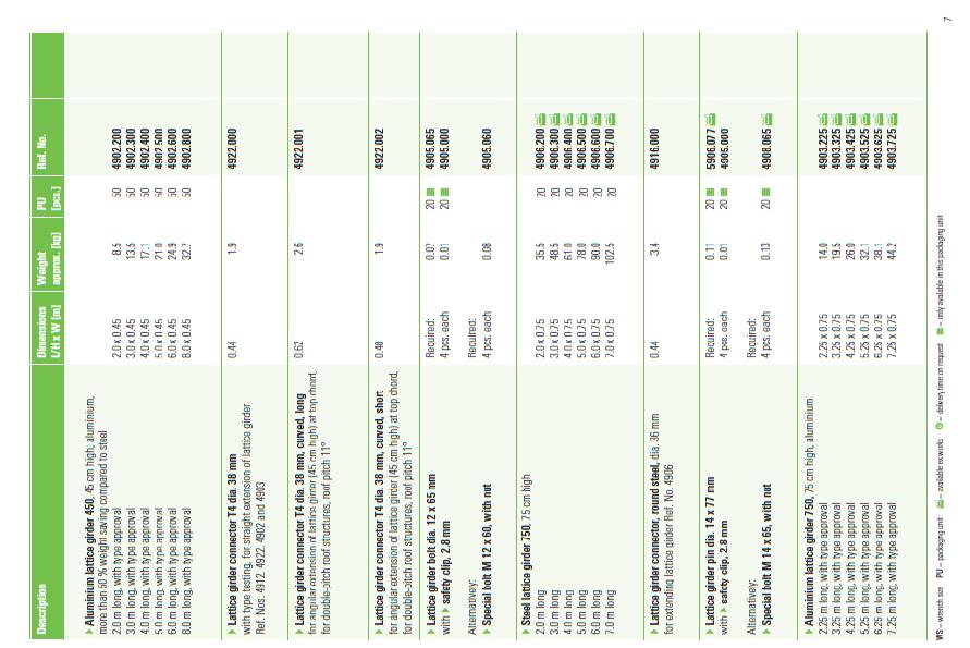
1 Layher Aluminium Lattice Beams Information and User Guide Aluminium Lattice Beam 450 (Product Code 4902XXX) Aluminium Lattice Beam 750 (Product Code 4903XXX)
2 Table of Contents Page 1 Introduction 2 2 General description 2 3 Coupler connections 2 4 Beam Bracing 2 5 Spigot connection 4 6 Methods for application of load and end supports 4 7 Permissible load capacity of beams 5 8 Permissible load capacity of couplers 7 9 Compliance of couplers 8 10 Extract from Layher Scaffolding Accessories Catalogue 9 Copyright All pictures, images and data of this Layher Aluminium Lattice Beams Information and User Guide are property of the company Wilhelm Layher GmbH & Co.KG, D Guglingen Eibensbach, Germany; phone * , Fax * They are furthermore protected according to the German copyright law. Copying, hiring or lending of these media to third parties is not permitted without the prior written permission of Wilhelm Layher GmbH & Co.KG. The usage of this document and its contents is only allowed in connection with the sale of products produced by Wilhelm Layher GmbH & Co.KG. If used, the document including all pictures and information must clearly indicate the origin and must refer to Wilhelm Layher GmbH & Co.KG. Prepared 21/05/12 1

3 1. Introduction This document is intended as a quick reference guide and is to be read in conjunction with the Layher Allround Instructions for Assembly and Use (Australia). This guide is for original Layher aluminium lattice beams only. Separate information on Layher s steel lattice beams is available from your local Layher representative. It is strongly recommended that all calculations based on the technical information presented in this guide be independently verified and checked by a qualified person such as an Engineer. The values in the below tables are base values only and are only for beams in a Simply Supported configuration. To achieve greater loads and spans, or obtain values for different beam configurations please contact your local Layher representative or a qualified engineer. 2. General description The top and bottom chords and the verticals of Layher aluminium lattice beams are made from 48.3mm diameter tube with thicknesses of 4.0mm for the 450 deep beams, and 4.5mm for the 750 deep beams, with oval sections for the diagonals. Beam lengths are generally at 1m increments up to 8m and sections can be joined together with 38mm diameter spigot connectors and 4 x M12 bolts. 3. Coupler connections The spacing of the diagonals on the lattice girders allows for connection of couplers to the top and bottom chords everywhere except where the verticals and diagonals meet. In these cases, the couplers can be connected to the vertical members. 4. Beam Bracing When the beam is spanning between two supports and the load is applied downwards, the compression chord is on the top. When load is upwards (predominantly wind uplift or cantilevers) the compression chord is on the bottom. See the following diagrams for a clearer explanation of how the compression chord changes from configuration to configuration. Prepared 21/05/12 2
4 Beam Configurations The chord highlighted in red is the compression chord. a. Simply Supported Beam b. Cantilevered Beams c. Simply Supported Beam (Uplift) d. Cantilevered Beam (with inboard load) e. Continuous Beam When bracing the Layher beams, it is important to brace the compression chord perpendicularly (chord to chord bracing) and diagonally (plan bracing) as well as tying the beams together with flybracings and tension chord bracing to stop the beams from twisting. This means that with some beam configurations when the compression chord changes from top to bottom chord along the span at different places, such as in continuous beams, both the top and bottom chords need the chord to chord bracing and the plan bracing. For more information regarding the bracing of the different beam configurations please contact your Layher representative or a qualified engineer. Warning: Incorrectly or inappropriately fitted beam bracing reduces the load bearing capacity and stability of the scaffolding structure significantly and can lead to its collapse. Prepared 21/05/12 3
 the top and bottom chords.")
5 The bracing arrangement below is for a Simply Supported Beam configuration with the load applied downwards. As shown in the above diagram, bracing should always be installed to the beams, primarily to (or adjacent to) the top and bottom chords. The compression chord should be braced in accordance with the loading requirements from the following tables, up to a maximum spacing of 2m (for beams greater than 3m long), with tension chord bracing and cross bracing at the ends and in the middle of the span. For beams of a length 4m or less the middle cross brace is not required. Plan bracing should also be installed to either the vertical struts of the beam near to the chord bracing or to the chord bracing itself. For bracing of other beam configurations please contact Layher. 5. Spigot connection The spigot to use in the spigot connection of both the aluminium lattice beam 450 and the aluminium lattice beam 750 is the Layher Unit beam spigot T4 (Product code ) and 4 x Layher M12 bolts and nuts (Product code ) or alternatively with 4 x Layher Lattice beam hinged pins dia. 12mm (Product code ). The permissible tension forces of the spigot connections are high enough for the safe transfer of the loads that occur during the stated permissible bending moments of the lattice beams. Permissible tension forces in the spigot connection of the 450mm Aluminium lattice beam: Permissible tension forces in the spigot connection of the 750mm Aluminium lattice beam: 39.1 kn 49.1 kn 6. Methods for application of load and end support Preferably the beams shall be supported by both its top and bottom chords. Supporting the beam in any other way seriously reduces the capacity and could lead to localised damage of the beam. Prepared 21/05/12 4

6 7. Permissible load capacity of beams a. Central Point Load b. Point load at third points c. UDL The values in the below tables are base values only and are only for beams in a Simply Supported configuration. To achieve greater loads and spans, or obtain values for different beam configurations please contact your local Layher representative or a qualified engineer. 450 Aluminium Beam Material: Alloy 6082T5 Self Weight: 0.05kN/m E: 70,000N/mm2 I: 4, cm4 Maximum Shear: 9.0kN Maximum Moment: 13.2kNm At 1m Bracing: 13.2kNm At 2m Bracing: 6.2kNm Image: Layher aluminium lattice beam 450 Length Top chord bracing intervals Central Point Load Point Load at Third Points UDL l(m) a [m] (kn) (kn) (kn/m) (3+4) Caution: Layher aluminium lattice beams CANNOT be used as anchor points for fall arrest systems according to loads specified in AS/NZS :2009. Prepared 21/05/12 5

7 The values in the below tables are base values only and are only for beams in a Simply Supported configuration. To achieve greater loads and spans, or obtain values for different beam configurations please contact your local Layher representative or a qualified engineer. 750 Aluminium Beam Material: Alloy 6082T6 Self Weight: 0.06kN/m E: 70,000N/mm2 I: 15, cm4 Maximum Shear: 14.4kN Maximum Moment: At 1m Bracing: 24.5kNm At 2m Bracing: 12.0kNm Image: Layher aluminium lattice beam 750 (in A Arrangement) Length Top chord bracing intervals Central Point Load Point Load at Third Points UDL l(m) a [m] (kn) (kn) (knm) ( ) Caution: Layher aluminium lattice beams CANNOT be used as anchor points for fall arrest systems according to loads specified in AS/NZS :2009. A vs. V Arrangement: The values in the table above for 750 aluminium beams are based on installation in A Arrangement. Significantly higher loads are achievable with the 750 aluminium beam in the V Arrangement. Please contact your Layher representative for more information. Notes: 1. Point loads should always be applied via the top and bottom chords, or distributed over a minimum length of 280mm. 2. All values are permissible with a loading factor of safety of 1.5, and take into account the self weight of the beams and bracing components. 3. When multiple beams are joined by spigots to span a distance in a dance floor scenario, the joints should be staggered in order to achieve more uniform deflections within the structure. 4. Appropriate couplers are to be used to apply the load and to attach the beams to the supporting structure. 5. Vertical load application should be avoided to spigot connections and additional load distribution should be used. 6. These load tables should be read in conjunction with Layher Instructions for Assembly and Use (Australia). Prepared 21/05/12 6
8 8. Permissible load capacity of couplers Layher Couplers, Layher Swivel couplers and Layher Sleeve couplers have received certification of compliance with EN74 1: The characteristic values of resistance for these couplers are shown in table C1 of EN :2003 and apply for connection to both steel and aluminium tubes. These figures should be divided by 1.65 to achieve safe working loads. Coupler Type Resistance Characteristic Values of Resistance Class A Class B Class AA Class BB Double Coupler (RA) Slipping Force FS,K in kn Swivel Angle Torque MB,K in knm 0.8 Head tear off force FP,K in kn Moment of Torque MT,K in knm 0.13 Swivel Coupler (SW) Slipping Force FS,K in kn Joint Coupler with Slipping Force FS,K in kn Friction Fit (SF) Bending Torque MB,K in knm 1.4 NB: For the above values to apply couplers need to be fastened with a torque of 50 Nm ± 10%. Layher double couplers: Layher Double couplers have been certified as Class BB couplers. If a Class BB coupler is used as a single coupler, then values of Class B apply. Safe working load of slipping force: F S,SWL = 9.1kN (F S,K = 15.0 kn) The slipping force of Class BB applies when the Layher double coupler is used in conjunction with a check coupler. Safe working load of slipping force: F S,SWL = 15.1kN (F S,K = 25.0 kn) Example end support of an Aluminium Lattice beam by Layher double and check couplers: Prepared 21/05/12 7

9 9. Compliance of Layher couplers AS/NZS Scaffolding Couplers and Accessories, Section 1 Compliance with International Standards, states the following: Couplers that have been tested and have demonstrated compliance with the performance requirements of BS EN 74 1:2005 for Class B right angle couplers and Class A swivel couplers, where these requirements are equivalent to the performance requirements of this Standard, are deemed to comply with this Standard and do not require further testing. Such couplers may not comply with dimensional requirements of this Standard and shall be assessed against these requirements before they are deemed acceptable. Layher couplers have received certification of compliance with BS EN74 1 and as per the above extract from AS/NZS do not require any further testing. A requirement of EN 74 1, clause 10 is to identify complying couplers with embossed lettering of which all Layher couplers have received. Image: Embossment of a Layher double coupler Prepared 21/05/12 8

10 Prepared 21/05/12 9
Allround Scaffolding. Layher Allround Bridging System Instructions for Assembly and Use. Modular truss system for wide spans
 Layher Allround Bridging System Instructions for Assembly and Use Modular truss system for wide spans Certification according to DIN ISO 9001/EN 29 001 by TÜV-CERT Allround Scaffolding } CONTENT 1. Introduction...3
Lattice Beam User Guide USG001-
 Lattice Beam User Guide Foreword DESSA offers efficient lightweight temporary roofing, encapsulation solutions, aluminium lattice girders and safety products. DESSA s unique and distinctive aluminium
PLETTAC METRIX COMPONENT CAPACITIES. Providing quality products and services at a competitive price.
 PLETTAC METRIX COMPONENT CAPACITIES Providing quality products and services at a competitive price. Valid Only For Genuine Equipment COMPONENT CAPACITIES COMPONENT CAPACITIES Loads given in this document
UNI Roof Catalogue CTG001-
 UNI Roof Catalogue Foreward DESSA offers efficient lightweight temporary roofing, encapsulation solutions, aluminium lattice girders and safety products. DESSA s unique and distinctive aluminium solutions
Allround Scaffolding. Propping Technical Brochure. The universal system for everyday and engineered scaffolding solutions
 Propping Technical Brochure The universal system for everyday and engineered scaffolding solutions made of galvanised steel or aluminium General construction approval Z-8.22-64 Quality management certified
Cut costs, improve safety, increase efficiency: Scaffolding for shipyards and offshore. Layher. More Possibilities. The Scaffolding System.
 Cut costs, improve safety, increase efficiency: Scaffolding for shipyards and offshore. Layher More Possibilities. The Scaffolding System. Made by Layher. Supply and service worldwide. Market leader in
Layher. Aluminium Rolling Towers. Layher SuperKlaxTower. Instructions for Assembly and Use
 Mobile access and working towers in accordance with: HD 1004; DIN 4422, Part 1 (Version 8/92) Working platform 2.8 x 2.8 m and 2.8 x 1.95 m Max. working height: in closed rooms 13.95 m, outdoors 10.0 m
PERI PD 8 The cost-effective shoring for slab tables and high loads
 PERI PD 8 The cost-effective shoring for slab tables and high loads Edition 06/2010 PERI GmbH Formwork Scaffolding Engineering P.O. Box 1264 89259 Weissenhorn Germany Tel +49 (0)7309.950-0 Fax +49 (0)7309.951-0
LAYHER ALLROUND SCAFFOLDING SHORING TG 60
 LAYHER ALLROUND SCAFFOLDING SHORING TG 60 Edition 05.2015 Ref. No. 8116.206 Quality management certified according to ISO 9001:2008 by German TÜV-CERT Allround Scaffolding LAYHER ALLROUND SCAFFOLDING THE
LAYHER ALLROUND SCAFFOLDING INSTRUCTIONS FOR ASSEMBLY AND USE
 LAYHER ALLROUND SCAFFOLDING INSTRUCTIONS FOR ASSEMBLY AND USE Edition 05.2013 Ref. No. 8116.230 Quality management certified according to DIN EN ISO 9001:2008 by TÜV-CERT CONTENTS 1. Introduction... 4
SJI Code of Standard Practice
 Standard Practice CODE OF STANDARD PRACTICE FOR STEEL JOISTS AND JOIST GIRDERS SECTION 1 GENERAL 1.1 SCOPE Adopted by the Steel Joist Institute April 7, 1931 Revised to May 18, 2010 - Effective December
Structural Design of Pergola with Airfoil Louvers
 International Journal of Advanced Structures and Geotechnical Engineering ISSN 2319-5347, Vol. 04, No. 03, July 2015 Structural Design of Pergola with Airfoil Louvers MUHAMMAD TAYYAB NAQASH Aluminium TechnologyAauxiliary
SCAFFOLDING RUNWAY SYSTEM
 SCAFFOLDING RUNWAY SYSTEM HANDBOOK 07/2017.3 i) Further information and detailed component information can be found in the: C1 Conveyor Systems Technical Catalogue. ii) Call or e-mail Niko Ltd for any
SECTION PLATE CONNECTED WOOD TRUSSES
 SECTION 06173 PLATE CONNECTED WOOD TRUSSES PART 1 GENERAL 1.01 SUMMARY A. Section Includes: 1. Shop fabricated wood trusses for roof and floor framing. 2. Bridging, bracing, and anchorage. B. Related Sections:
Lecture Retaining Wall Week 12
 Lecture Retaining Wall Week 12 Retaining walls which provide lateral support to earth fill embankment or any other form of material which they retain them in vertical position. These walls are also usually
UNIVERSITY OF BOLTON WESTERN INTERNATIONAL CENTRE FZE. BEng (HONS) CIVIL ENGINEERING SEMESTER ONE EXAMINATION 2015/2016
 CIVIL ENGINEERING SEMESTER ONE EXAMINATION 2015/2016") OCD59 UNIVERSITY OF BOLTON WESTERN INTERNATIONAL CENTRE FZE BEng (HONS) CIVIL ENGINEERING SEMESTER ONE EXAMINATION 2015/2016 ADVANCED STRUCTURAL ANALYSIS AND DESIGN MODULE NO: CIE6001 Date: Tuesday 12
OCD59 UNIVERSITY OF BOLTON WESTERN INTERNATIONAL CENTRE FZE BEng (HONS) CIVIL ENGINEERING SEMESTER ONE EXAMINATION 2015/2016 ADVANCED STRUCTURAL ANALYSIS AND DESIGN MODULE NO: CIE6001 Date: Tuesday 12
Contents DESIGNER S STRUCTURAL PRODUCTS GUIDE. Tegral Purlins & Rails
 DESIGNER S STRUCTURAL PRODUCTS GUIDE Introduction Contents Tegral Purlins & Rails Zeta Purlins & Rails Zeta Purlins page 8 Zeta Rails page 15 Zeta Purlin & Rail Cleats page 22 Zeta 2 Purlins & Rails Zeta
CODE OF STANDARD PRACTICE
 CODE OF STANDARD PRACTICE FOR STEEL JOISTS AND JOIST GIRDERS SECTION 1. GENERAL 1.1 SCOPE Adopted by the Steel Joist Institute April 7, 1931 Revised to Nov. 10, 2014 - Effective Jan.1, 2015 The practices
DATA SHEET 3 Concrete Masonry Lintels MARCH 2013
 Concrete Masonry Association Australia PO Box, P: Artarmon F: NSW www.cmaa.com.au Disclaimer: The Concrete Masonry Association of Australia Limited is a non-profit organisation sponsored by the concrete
ME-313 STRENGTH OF MATERIALS October 11, 2000 TEST I OPEN TEXT BOOK
 ME-313 STRENGTH OF MATERIALS October 11, 000 TEST I OEN TEXT BOOK Name: 1. Three plates of are bolted together as shown in the figure below. Design the bolted connection by choosing both plate thickness
Product overview:
 Product overview: The diagram gives an overview of the dimensions, and therefore the spectrum of structural performance, of the different types of Kielsteg elements. Structural performance: Thanks to their
FEATURES APPLICATIONS. Technical data sheet SSW - STEEL STRONG-WALL FOR TIMBER FRAME RACKING RESISTANCE.
 The Steel Strong-Wall is a corrugated steel panel which is designed to be fixed directly to the concrete foundations of a building, within the external or internal wall, via a bolted connection. FEATURES
SECTION VIBRATION CONTROLS FOR HVAC PIPING AND EQUIPMENT
 SECTION 230548 - PART 1 - GENERAL 1.1 SUMMARY A. This Section includes the following: 1. Elastomeric Isolation pads. 2. Elastomeric Isolation mounts. 3. [Freestanding] [Restrained] [Freestanding and restrained]
USING WOOD STRUCTURAL PANELS FOR SHEAR AND WIND UPLIFT APPLICATIONS
 USING WOOD STRUCTURAL PANELS FOR SHEAR AND WIND UPLIFT APPLICATIONS Borjen Yeh 1 and Ed Keith 2 ABSTRACT: Shearwalls constructed with wood structural panels, such as plywood and oriented strand board (OSB),
Layher Allround Scaffolding
 Faster. Stronger. Safer. More Profitable. Allround Scaffolding Comparison with Kwikstage Faster. Superior system technology. 59% Savings in Time Savings in time from superior system technology: 8 hole
LAYHER EVENT SYSTEMS CATALOGUE
 LAYHER EVENT SYSTEMS CATALOGUE Edition 04.2015 Ref. No. 8111.227 Quality management certified according to ISO 9001:2008 by German TÜV-CERT Layher QUALITY MADE BY LAYHER Headquarters in Eibensbach Plant
Suojatuote PROxA Weather Protection System Installation Manual. Suojatuote Pro Oy Rastaansiipi 15 D Oulu Suomi
 Suojatuote PROxA Weather Protection System Installation Manual Suojatuote Pro Oy Rastaansiipi 15 D 10 90650 Oulu Suomi General The Weather Protection System is a temporary roof system that protects from
Types Of Roofs - Vault
 1 Types Of Roofs - Vault Implementation Of the Concrete On Vault Implementation Of Vault Earthquake Damage 2 Types Of Roofs - Joist And Block 3 Types Of Coverage Roofs-Composite 4 5 Building Structure
EVALUATION REPORT. PFC-5551 Reissued April 1, Filing Category: DESIGN Steel (038)
") ICBO Evaluation Service, Inc. 5360 WORKMAN MILL ROAD WHITTIER, CALIFORNIA 90601-2299 A subsidiary corporation of the International Conference of Building Officials EVALUATION REPORT Copyright 2001 ICBO
ICBO Evaluation Service, Inc. 5360 WORKMAN MILL ROAD WHITTIER, CALIFORNIA 90601-2299 A subsidiary corporation of the International Conference of Building Officials EVALUATION REPORT Copyright 2001 ICBO
EXCEL MODULAR STANDARD SCAFFOLD COMPONENT TECHNICAL MANUAL
 EXCEL MODULAR STANDARD SCAFFOLD COMPONENT TECHNICAL MANUAL EMSLC-TSM-1001 Engineering Approval: Lance Smith Manual Release Date: 04/25/2017 Release Authorization: ECN EMSLC-0191 Revision: AK TABLE OF
INNOVATION IN PROP DESIGN. For propping enquiries Australia wide call:
 Propping Equipment INNOVATION IN PROP DESIGN A leader in innovative design, Coates Hire has designed the Universal Prop System 30 and 60 to meet challenging applications. Able to prop up to 30 and 60 tonne
Steel Floor Framing Solutions
 Steel Floor Framing Solutions Complete packages for domestic floors, decks and additions Product Manual & General Information Individually designed solutions Full design and quote service Drawings and
LAYHER SPEEDYSCAF SYSTEM CATALOGUE
 LAYHER SPEEDYSCAF SYSTEM CATALOGUE Edition 04.2013 8102.254 Quality management certified according to ISO 9001:2008 by German TÜV-CERT Layher QUALITY MADE BY LAYHER // Main plant in Eibensbach // Plant
SAMPLE TC6K Elevator Design Summary. Order No PO-47201
 SAMPLE TC6K Elevator Design Summary 900 RR 620 S., Ste C206 Austin TX 78734 (512) 266-6200 voice (512) 266-6210 fax SAMPLE CCR TC6K Elevator Design Summary - Elevator System Design Parameters Nominal Height
Chapter. Steel Member Design
 Chapter Steel Member Design The steel member design modules can be used for elastic and plastic design of structural steel members. Several modules act as post-processors for the frame analysis modules,
SpeedyScaf System. Layher SpeedyScaf System. Catalogue Edition Quality management certified according to ISO 9001:2008 by German TÜV-CERT
 C o m p l e t e. Quality management certified according to ISO 9001:2008 by German TÜV-CERT S a f e. 8102.253 Q u i c k. Catalogue Edition 01.04.2012 SpeedyScaf System Layher SpeedyScaf System u Contents
Panel Jack Pro System BRACING, ALIGNMENT AND SCAFFOLDING EQUIPMENT
 IMPORTANT SAFETY INFORMATION FOR USERS OF THE REECHCRAFT, BRACING SYSTEM PLEASE READ BEFORE USE Panel Jack Pro System BRACING, ALIGNMENT AND SCAFFOLDING EQUIPMENT UK Edition 1.3 26/11/2012 1 TABLE OF CONTENTS
Graphic truss analysis. Graphic truss analysis Copyright Prof Schierle
 Graphic truss analysis Graphic truss analysis Copyright Prof Schierle 2011 1 Truss examples Oakland Bay Bridge Truss joists Graphic truss analysis Copyright Prof Schierle 2011 2 Stadium roof Milan Airport
STRUCTURAL CALCULATIONS
 STRUCTURAL CALCULATIONS FOR BALUSTRADES USING BALCONY 1 SYSTEM HANDRAIL WITH INTERNAL 58 x 4mm STEEL REINFORCING BAR AND WITH 48.3mm DIAMETER X 5mm STEEL STANDARDS BY BALCONY SYSTEMS LIMITED Balcony 1
At last! Construction bracing made easy...
 At last! Construction bracing made easy...... a fast, smart and simple system with a range of applications THE SMART BRACING SYSTEM There are many situations in building with a need for the bracing of
On Cold-Formed Steel Construction. Light Gauge Steel Engineers Association Washington, D.C Toll Free (866)
") TECHNICAL NOTE On Cold-Formed Steel Construction $5.00 Light Gauge Steel Engineers Association Washington, D.C. 20005 Toll Free (866) 465-4732 www.lgsea.com DESIGN OF BY-PASS SLIP CONNECTORS IN COLD-FORMED
TECHNICAL NOTE On Cold-Formed Steel Construction $5.00 Light Gauge Steel Engineers Association Washington, D.C. 20005 Toll Free (866) 465-4732 www.lgsea.com DESIGN OF BY-PASS SLIP CONNECTORS IN COLD-FORMED
PORTAL FRAMES 1.0 INTRODUCTION
 36 PORTAL FRAMES 1.0 INTRODUCTION The basic structural form of portal frames was developed during the Second World War, driven by the need to achieve the low - cost building envelope. Now they are the
Renovation of Buildings using Steel Technologies (ROBUST)
") Renovation of Buildings using Steel Technologies (ROBUST) RFCS Project RFSR-CT-2007-0043 WP 4.2 Renovation of roofs using open trusses in light steel C sections Date: 2009 Author: Mark Lawson SCI, Silwood
Renovation of Buildings using Steel Technologies (ROBUST) RFCS Project RFSR-CT-2007-0043 WP 4.2 Renovation of roofs using open trusses in light steel C sections Date: 2009 Author: Mark Lawson SCI, Silwood
WIND SPEED AND DESIGN CRITERIA FOR FLEXIBLE FACE SIGNS CONSTRUCTED OF ABC EXTRUSIONS
 WIND SPEED AND DESIGN CRITERIA FOR FLEXIBLE FACE SIGNS CONSTRUCTED OF ABC EXTRUSIONS 2005 EDITION This edition is based upon ASCE 7-98 recommendations for wind speed and wind loads. These have changed
Council on Tall Buildings
 Structure Design of Sino Steel (Tianjin) International Plaza Xueyi Fu, Group Chief Engineer, China Construction Design International 1 1 Brief of Project 2 Location: Tianjin Xiangluowan Business District
DESIGN OF WALLS FOR SHEAR
 mortarless masonry Design Manual Part 3 (IS 456:2000) Section 5 Page: 1 SECTION 5. DESIGN OF WALLS FOR SHEAR Shear walls: Load-bearing walls are mostly designed to carry axial compression loads, however
SECTION VIBRATION AND SEISMIC CONTROLS FOR ELECTRICAL SYSTEMS
 PART 1 - GENERAL 1.1 RELATED DOCUMENTS A. Drawings and general provisions of the Contract, including General and Supplementary Conditions, apply to this Section. 1.2 SUMMARY A. This Section includes the
KSK COLLEGE OF ENGINEERING AND TECHNOLOGY DEPARTMENT OF CIVIL ENGINEERING CE 2505-DESIGN OF RC ELEMENTS QUESTION BANK
 KSK COLLEGE OF ENGINEERING AND TECHNOLOGY DEPARTMENT OF CIVIL ENGINEERING CE 2505-DESIGN OF RC ELEMENTS QUESTION BANK PARTA UNIT I 1. What are the advantages of limit state method over working stress and
KINETICS Seismic & Wind Design Manual Section D9.0
 KINETICS Seismic & Wind Design Manual Section D9.0 SECTION D9.0 TABLE OF CONTENTS Title Revision Record Section D9.0A D9.0 Electrical Distribution Systems Title Section Seismic Forces Acting On Cable Trays
Comparative Study of R.C.C and Steel Concrete Composite Structures
 RESEARCH ARTICLE OPEN ACCESS Comparative Study of R.C.C and Steel Concrete Composite Structures Shweta A. Wagh*, Dr. U. P. Waghe** *(Post Graduate Student in Structural Engineering, Y.C.C.E, Nagpur 441
Universal Panels & Accessories
 Universal Panels & Accessories Erection Procedures INTRODUCTION Use common sense when working with Scaffold Your Safety is our #1 Concern Universal Scaffolds are designed with your safety in mind every
DIVISION: METALS SECTION: STEEL DECKING REPORT HOLDER: EPIC METALS CORPORATION 11 TALBOT AVENUE RANKIN, PENNSYLVANIA 15104
 0 Most Widely Accepted and Trusted ICC ES Evaluation Report ICC ES 000 (800) 423 6587 (562) 699 0543 www.icc es.org ESR 2047 Reissued 07/207 This report is subject to renewal 07/209. DIVISION: 05 00 00
COLUMN SHOES HPKM, PPKM, PEC
 COLUMN SHOES HPKM, PPKM, PEC Version 9/2007 (Update 7/2009) Replaces brochure /2006 HPKM, PPKM, PEC -column shoes Benefits of Peikko -column joints Saves time, costs and materials Easy and fast adjustments
LPI 56 Technical Guide
 LPI 56 Technical Guide Floor & Roof Applications Product Specifications & Design Values 2 Floor Tables 3 Uniform Floor Load (PLF) Tables: Simple s 4 Uniform Floor Load (PLF) Tables: Continuous s 5 Uniform
HT 20plus. Formwork timber beams. Facts on formwork timber beams: Contents. Product standard. Wood types. Beam height. Weight.
 Formwork timber beams Facts on formwork timber beams: Contents Wood types Spruce / Fir Beam height 20 cm Lengths Lengths up to 10 m Product standard Technical approval certificate Z-9.1-146 Weight 4,6
PLETTAC METRIX USER GUIDE
 PLETTAC USER GUIDE Providing quality products and services at a competitive price. Valid Only For Genuine Equipment DISCLAIMER: Whilst TRAD Hire & Sales Ltd and the author have made every reasonable effort
Layher SpeedyScaf Instructions for Assembly and Use
 Layher SpeedyScaf Instructions for Assembly and Use Edition 11.2013 Ref. No. 8102.230 Quality management certified according to DIN EN ISO 9001:2008 by TÜV-CERT Contents 1. Introduction... 4 2. Measures
SHOT FIRED DOWEL FLITCH BEAMS
 SHOT FIRED DOWEL FLITCH BEAMS Robert Hairstans 1, Abdy Kermani 2 and Rod Lawson 3 1&2 School of the Built Environment, Napier University, Edinburgh 3 Oregon Timber Frame, Jedburgh E-mail: r.hairstans@napier.ac.uk
5.4 Analysis for Torsion
 5.4 Analysis for Torsion This section covers the following topics. Stresses in an Uncracked Beam Crack Pattern Under Pure Torsion Components of Resistance for Pure Torsion Modes of Failure Effect of Prestressing
DESIGN FOR PROGRESSIVE COLLAPSE 1
 Your Partner in Structural Concrete Design TN447_progressive_collapse_110713 DESIGN FOR PROGRESSIVE COLLAPSE 1 Bijan O Aalami 2 This Technical Note outlines the design of column-supported conventionally
BoSS Climalite Camera and lighting tower
 Contents Safety First Safety First Quantity Schedules Toeboard 2 9 13 33 INTRODUCTION Please read this guide carefully. Please note that diagrams are for illustrative purposes only. User guides are also
General HANDLING, ASSEMBLY, AND USE OF TRUSSES
 General HANDLING, ASSEMBLY, AND USE OF TRUSSES Load, unload, or move trusses with the necessary personnel to assure that the trusses are not dragged or dropped; this may damage the ends and the structure
Anchor bolts ASTM F1554, Gr. 36 Wide flange beams ASTM A992, Fy = 50 ksi Misc. structural steel ASTM A36, Fy = 36 ksi
 STRUCTURAL NOTES MATERIAL STRENGTHS Structural Steel Reinforcing Steel Concrete Masonry Structural Lumber Anchor bolts ASTM F1554, Gr. 36 Wide flange beams ASTM A992, Fy = 50 ksi Misc. structural steel
EN REINFORCED MASONRY DESIGN EXAMPLE 1 (NOTE: THIS USES THE UK NATIONAL ANNEX NDP VALUES)
") 42.50 10.00 3.00 20.00 EN 1996-1-1 REINFORCED MASONRY DESIGN EXAMPLE 1 (NOTE: THIS USES THE UK NATIONAL ANNEX NDP VALUES) Reinforced Masonry - Reinforced Brickwork Stem Cantilever Pocket-Type Retaining
42.50 10.00 3.00 20.00 EN 1996-1-1 REINFORCED MASONRY DESIGN EXAMPLE 1 (NOTE: THIS USES THE UK NATIONAL ANNEX NDP VALUES) Reinforced Masonry - Reinforced Brickwork Stem Cantilever Pocket-Type Retaining
distribution Modular Scaffolding
 Modular Scaffolding Modular scaffolding PDM Universal scaffolding system plettac-pl PDM Application A characteristic feature of plettac PDM system is the use of wedge joint which provides quick and safe
Standards for Testing and Rating Shoring Equipment
 ANSI/SSFI SH300-2007 American National Standard Standards for Testing and Rating Shoring Equipment Scaffolding, Shoring & Forming Institute, Inc. Sponsor: Scaffolding, Shoring & Forming Institute, Inc.
Adjusta Minit Anti-Surf
 Adjusta Minit Anti-Surf The One Piece Adjustable Folding Work Platform» New slip resistant front feet» Adjustable to 4 different platform levels» Guardrail automatically in place» No loose components»
Layher. Allround Scaffolding. Made of galvanised steel or corrosion-proof aluminium. General construction approvals Z , Z
 Made of galvanised steel or corrosion-proof aluminium General construction approvals Z-8.22-64, Z-8.22-64.1 Quality management certified according to DIN EN ISO 9001:2000 by German TÜV-CERT Allround Scaffolding
CODE OF STANDARD PRACTICE
 CODE OF STANDARD PRACTICE FOR CJ-SERIES COMPOSITE STEEL JOISTS Adopted by the Steel Joist Institute May 10, 2006 Revised to May 18, 2010 - Effective December 31, 2010 Revised to November 9, 2015 Effective
R-Group Finland Oy. REA Lifting Inserts Technical Manual According to Eurocodes, EU Machinery directive 2006/42/EC and VDI/BV-BS 6205 CE Approved
 R-Group Finland Oy REA Lifting Inserts Technical Manual According to Eurocodes, EU Machinery directive 2006/42/EC and VDI/BV-BS 6205 CE Approved 10.2.2017 2 Table of Contents 1 DESCRIPTION OF THE SYSTEM...
Wood Solutions Fair, 2014, Toronto
 Overview of Changes to CSA O86-2014 & Structural Design Provisions for Mid-Rise in OBC Wood Solutions Fair, 2014, Toronto Jasmine Wang, Ph.D., P.Eng. Canadian Wood Council Copyright Materials This presentation
SECTION HANGERS AND SUPPORTS FOR ELECTRICAL SYSTEMS
 SECTION 26 05 29 HANGERS AND SUPPORTS FOR ELECTRICAL SYSTEMS PART 1 GENERAL 1.1 DESCRIPTION A. Scope: 1. CONTRACTOR shall provide all labor, materials, equipment, and incidentals as shown, specified, and
ACCEPTANCE CRITERIA FOR HELICAL PILE SYSTEMS AND DEVICES PREFACE
 www.icc-es.org (800) 423-6587 (562) 699-0543 A Subsidiary of the International Code Council ACCEPTANCE CRITERIA FOR HELICAL PILE SYSTEMS AND DEVICES AC358 Approved June 2012 Compliance date December 1,
FE Review Mechanics of Materials
 1 2 3 4 5 6 7 8 9 10 11 12 13 14 15 16 17 18 19 20 21 22 23 24 25 26 27 28 29 1. T he element is subjected to the plane stress condition shown. a-x = - 140 M Pa a- y = 205 M Pa Txy = 100 M Pa What is t
HILLSBOROUGH TOWNSHIP CODE ENFORCEMENT
 HILLSBOROUGH TOWNSHIP CODE ENFORCEMENT SAMPLE GUIDE FOR RESIDENTIAL DECKS revised 7 16 Call before you dig! 1 800 272 1000 New Jersey One Call. Utility Mark Out. THIS GENERIC GUIDE IS NOT ALL INCLUSIVE
REPORT HOLDER: FASTENING SPECIALISTS, INC. 726 CENTRAL FLORIDA PARKWAY ORLANDO, FLORIDA EVALUATION SUBJECT:
 0 Most Widely Accepted and Trusted ICC ES Evaluation Report ICC ES 000 (800) 423 6587 (562) 699 0543 www.icc es.org ESR 2328 Reissued 10/2017 This report is subject to renewal 10/2018. DIVISION: 03 00
R-Group Finland Oy. RTA, RWTL and RWTS Lifting anchors Design instructions
 R-Group Finland Oy RTA, RWTL and RWTS Lifting anchors Design instructions According to Eurocodes, EU Machinery directive 2006/42/EC and VDI/BV-BS 6205 CE Approved 28.12.2016 2 Table of contents 1 DESCRIPTION
EN DK NA:2007
 EN 1995-1-1 DK NA:2007 National Annex to Eurocode 5: Design of timber structures - Part 1-1: General - Common rules and rules for buildings Foreword In connection with the incorporation of Eurocodes into
SPECIFICATION FOR REINFORCED SOIL WALL
 SPECIFICATION FOR REINFORCED SOIL WALL 1.0 EXTENT OF WORK The work shall consist of Reinforced Soil walls built in accordance with this specification and in conformity with the lines, levels and details
Diaphragms 2. Design Process. Design Process. Diaphragms are the roofs and floors of the upper stories
 Diaphragms 2 Design Process Diaphragms are the roofs and floors of the upper stories They are assumed to act as a beam (usually a deep beam with substantial shear deformation) Design Process Sheathing
Chapter 3: Torsion. Chapter 4: Shear and Moment Diagram. Chapter 5: Stresses In beams
 Chapter 3: Torsion Chapter 4: Shear and Moment Diagram Chapter 5: Stresses In beams Torsion Torsion or Torque, T, put simply, is referred to as a twisting moment. θ The derived formulas are: Where: Torsional
STRUCTURAL CALCULATIONS
 STRUCTURAL CALCULATIONS FOR JULIET BALCONY BALUSTRADES USING 21.5mm LAMINATED GLASS SYSTEM BY Balcony Systems Solutions Ltd Unit 6 Systems House Eastbourne Road Blindley Heath Lingfield Surrey RH7 6JP
Easy Rider Mooring. Design Assessment. For. Advanced Mooring Technology CONSTRUCTION. Authorised:
 M C A L P I N E M A R I N E D E S I G N P T Y L T D ACN 003 056 399 Easy Rider Mooring Design Assessment For Advanced Mooring Technology Project No. 04003 Rev. 0 Status: Authorised: CONSTRUCTION / / Copyright
DIVISION: EARTHWORK SECTION: BORED PILES REPORT HOLDER: GEOTECH ENTERPRISES, INC.
 0 Most Widely Accepted and Trusted ICC ES Report ICC ES 000 (800) 423 6587 (562) 699 0543 www.icc es.org ESR 3623 Reissued 04/2017 This report is subject to renewal 04/2018. DIVISION: 31 00 00 EARTHWORK
G.B.M. building equipments PONTEGGI. Parapetti Certifi cati SHUTTERING PANELS AND FORMWORK H20 BEAMS
 Parapetti Certifi cati d ng equip SHUTTERING PANELS AND FORMWORK H0 BEAMS shuttering panels are high-quality, -ply wooden panels, made of spruce and fir wood acquired from sustainable forests. The panels
2012 Wood Frame Construction Manual: Wind Load Distribution on Buildings Load Paths
 2012 Wood Frame Construction Manual: Wind Load Distribution on Buildings Load Paths Presented by: William L. Coulbourne, PE Copyright Materials This presentation is protected by US and International Copyright
Pull-Through Failure Tests of Thin Steel Roof Battens under Wind Uplift Loads
 Missouri University of Science and Technology Scholars' Mine International Specialty Conference on Cold- Formed Steel Structures (2014) - 22nd International Specialty Conference on Cold-Formed Steel Structures
Strength Study on Castellated Beam
 Strength Study on Castellated Beam 1 B. Anupriya 2 Dr. K. Jagadeesan 1 Assistant Professor Department of Civil Engineering Arasu Engineering College, Kumbakonam, Tamilnadu, India 2 Professor Department
The following are details of the code requirements of the 2015 International Residential Code for single-story decks.
 The following are details of the code requirements of the 2015 International Residential Code for single-story decks. The 2015 International Residential Code Section R507 contains additional information
D D TYPE A1, A2 & B MICHIGAN DEPARTMENT OF TRANSPORTATION 5-40 CONNECTION. L4" x 4" x 3/8" Brace. C8 x 4.25 Strut. WT9 x 17.5.
 Sign length minus Adjust to avoid interference with sign legend A Deck fascia A 6" Equal Equal 6" Sign length (L) varies 6 to 12 PLAN 0 CONNECTION (DECK FASCIA) Angle connection assembly F Face of concrete
TERWA REBAR CONNECTION COUPLERS
 TERWA REBAR CONNECTION COUPLERS CARES Technical Approval 5058 TA1B Introduction The Terwa Parallel Threaded Coupler is a full bar strength system (the coupling is stronger than the associated rebar, sometimes
ATI Evaluation Service A Division of Architectural Testing Certification Services
 ATI Evaluation Service A Division of Architectural Testing Certification Services Subject to Renewal: 08/09/2014 Issued: 08/09/2013 Visit www.ati-es.com for current status Revised: 08/12/2013 Page 1 of
A division of Canam Group
 s and Girders Catalogue A division of Canam Group TABLE OF CONTENTS Products, services and solutions.... 4 General information The advantages of using steel joists... 5 Description of a joist girder....5
SJI Updates Expanded Load Tables for Noncomposite Joists / Joist Girders and Development of New Composite Joist Series
 SJI Updates Expanded Load Tables for Noncomposite Joists / Joist Girders and Development of New Composite Joist Series SUMMARY David Samuelson Steel joists are growing in recognition as being a very economical
Open-Web Trusses. Including Red-L, Red-W, Red-S, Red-M and Red-H Trusses. Design Flexibility. Outstanding Strength-to-Weight Performance
 Open-Web Trusses Including Red-L, Red-W, Red-S, Red-M and Red-H Trusses Download your free copy at RedBuilt.com. Specify Open-Web trusses for your next project using RedSpec single-member sizing software.
SECTION ELEVATED BLEACHERS (Angle Frame Semi-Closed Deck)
") SECTION 13125 ELEVATED BLEACHERS (Angle Frame Semi-Closed Deck) PART 1 GENERAL 1.1 RELATED DOCUMENTS A. Drawings and general provisions of the Contract, including General and Supplementary Conditions and
SECTION 13125 ELEVATED BLEACHERS (Angle Frame Semi-Closed Deck) PART 1 GENERAL 1.1 RELATED DOCUMENTS A. Drawings and general provisions of the Contract, including General and Supplementary Conditions and
Sabah Shawkat Cabinet of Structural Engineering 2017
 3.1-1 Continuous beams Every building, whether it is large or small, must have a structural system capable of carrying all kinds of loads - vertical, horizontal, temperature, etc. In principle, the entire
Erection manual. Tube-Lock Concept. van Thiel United b.v Page: 1 of 15
 Erection manual Tube-Lock Concept 2013-02 Page: 1 of 15 Contents Subject Page Illustration of Tube-Lock Concept 3 Parts of Tube-Lock concept 4 Legislation 5 Erecting a Tube-Lock Concept scaffold 6 Technical
CUPLOK SGB CUPLOK SGB Group
 CUPLOK USER S MANUAL CONTENTS Page Introduction 5 The CUPLOK locking procedure 6 CUPLOK safety information 7 General site safety 9 Core components 11 Scaffold system components 12 Ancillary components
D E U T S C H E S I N S T I T U T F Ü R B A U T E C H N I K
 D E U T S C H E S I N S T I T U T F Ü R B A U T E C H N I K Corporation under Public Law 10829 Berlin, 17 July 2002 Kolonnenstraße 30 L Telefon: (0 30) 7 87 30-356 Telefax: (0 30) 7 87 30-320 GeschZ.: