Concrete Slab Track Test on the High Tonnage Loop. at the Transportation Technology Center. AREMA Annual Conference & Exposition
|
|
|
- Maude Allen
- 6 years ago
- Views:
Transcription
1 AREMA Annual Conference & Exposition September 2005 Chicago, Illinois Concrete Slab Track Test on the High Tonnage Loop at the Transportation Technology Center by David N. Bilow, P.E., S.E. Director, Engineered Structures Portland Cement Association 5420 Old Orchard Road Skokie, IL Tel Fax and Dinqing Li, PhD, P.E. Principal Engineer Transportation Technology Center, Inc DOT Road P.O. Box Pueblo, CO Tel (719) Fax (719)
2 ABSTRACT This paper presents results of field testing of two slab track sections on the High Tonnage Loop (HTL) at the Transportation Technology Center (TTC) in Pueblo, Colorado. The test at TTC is part of the Cooperative Slab Track Research and Demonstration Program for Shared Freight and High Speed Passenger Service initiated by the Portland Cement Association (PCA) in The objective of the program is to advance concrete slab track technology and to demonstrate the capability of slab track to provide a low maintenance and safe track structure for shared highspeed rail and freight on U.S. railroads. As part of the program, laboratory tests were performed on two types of slab track and the results were presented at the July 2003 AREMA Conference by PCA. One type of slab track uses direct fixation fasteners mounted to the top surface of a concrete slab and the second type uses independent dual concrete block ties with rubber boots and pads embedded in the concrete slab. In the summer of 2003, following successful completion of the laboratory tests, a 550 foot test section of slab track was constructed at TTC on the HTL. The slab track test at TTC is sponsored by the Federal Railroad Administration (FRA) and PCA. The FAST train at TTC using 315,000-lb freight cars (39 ton axle loads) has accumulated over 100 million gross tons of traffic on the test section. Results show that slab track can accommodate the heavy axle freight rail loads while maintaining the vertical and horizontal geometry required by high speed rail. Key Words: concrete, freight railroad, high-speed trains, railroad track, shared corridor, slab track, R & D, structural design, transitions, high axle load, Transportation Technology Center, safe track, rail transit
3 INTRODUCTION The expansion of high speed rail (HSR) corridors and the increasing use of heavy axle load freight cars in the U.S. influenced the Portland Cement Association (PCA) in 2000 to study slab track as an alternative to ballasted track. PCA also realized that in the U.S. for some corridors, high speed rail passenger trains would most likely share track with freight trains because of the high cost of track construction and maintenance. The challenge is to design and construct a track system that provides the required track geometry for future high-speed passenger trains traveling up to 200 mph and the strength to withstand repeated heavy axle loads from freight trains. It was also understood that ballast is the main source of average and differential settlement in most track as stated in Track Geotechnology and Substructure Management by Ernest T. Selig and John M. Waters. To address this challenge, PCA created the Cooperative Concrete Slab Track Research and Demonstration Program for Shared Freight and High Speed Passenger Service. The objective of the program is to advance concrete slab track technology and to demonstrate the capability of slab track to provide a low maintenance and safe track structure for shared high speed rail and heavy freight on U.S. railroads. PCA initiated work on the program in 1999 and prepared the paper Concrete Slab Track for Freight and High Speed Service Applications, a Survey of Practice which was published in Transportation Research Record in 2001 by TRB. PCA also organized a panel of experts to advise PCA on the slab track program and initiated full scale laboratory tests on two types of slab track: direct fixation slab track (DFST) and independent dual block slab track (IDBT). After completion of the successful laboratory tests, construction started in 2003 on a 550 foot long slab track test section at the Transportation Technology Center (TTC) in Pueblo, Colorado. The objectives of the work at TTC are to build and test a prototype section of slab track in order
4 to validate the design procedure developed by CTLGroup for PCA, validate the laboratory tests, and to demonstrate slab track s durability for heavy, high traffic loads while maintaining the track geometry required by HSR at low maintenance cost. The two year test on the High Tonnage Loop (HTL) of the Facility for Accelerated Service Testing (FAST) at TTC has subjected the slab track to more than 100 million gross tons (mgt) of heavy axle (39 ton) load freight traffic as of June The Federal Railroad Administration (FRA) and PCA sponsor the field test which will be extended until September 2006 to accumulate an additional 50 mgt. This paper describes the slab track test section, measurement procedures, and summarizes the results of the test to date. TEST ENVIRONMENT TTC, the largest railroad test facility in the world, is owned by FRA and is operated by the Transportation Technology Center, Inc. (TTCI), a subsidiary of the Association of American Railroads. The facility is located on semi arid land 21 miles east of Pueblo, Colorado. The record summer high temperature is 108 degrees and record winter low temperature is -30 degrees (F). The slab track test section was constructed on the HTL. The HTL is 2.7 miles long and is used for track component reliability, wear, and fatigue research under heavy axle (39 ton) loads. The test train generally has four locomotives and about 70 cars each weighing 315,000 pounds. The HTL is divided into test sections which generally correspond to tangents, spirals, curves and turnouts. The slab track test section is located in the bypass track on section 38 as shown in Figure 1. Section 38 is a five degree curve with a 4 superelevation and was selected to demonstrate slab track performance under severe curvature conditions. The test train operation generally accumulates 1.0 mgt a day at a nominal speed of 40 miles per hour. Specialized test consists such as the track loading vehicle (TLV) and track geometry measurement system (TGMS) can apply specific loads to the track and perform various measurements.
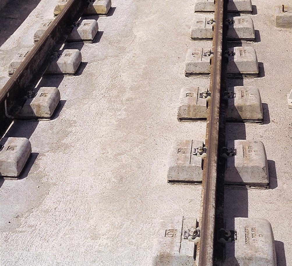
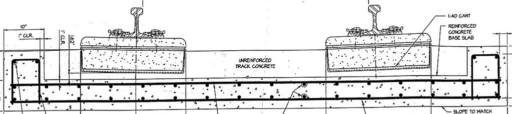
5 SLAB TRACK TEST SECTION The slab track test section consists of 250 feet of DFST, 250 feet of IDBT, and two pieces of transition track each 25 feet long between each end of the slab track and the adjacent ballasted track. The slab track was constructed to tolerances equal to the more stringent of FRA Class 9 Track Safety Standards and Amtrak s construction tolerance for HSR as shown in Table 1. These two types of cast-in-place (CIP) slab track were selected because several versions of the DFST are in service on passenger and freight track in North America and the IDBT is in service on the heavily traveled Eurotunnel beneath the English Channel. However, the existing slab track installations are not subject to 39 ton axle loads or high speed traffic. The DFST is a 12 inch thick concrete slab 10-6 wide with 5,000 psi concrete and two mats of steel reinforcement as shown in Figure 2. The DFST uses the Acoustic Loadmaster DF track fastener manufactured by Advanced Track Products, Inc., made of ductile iron and natural rubber and spaced at two foot intervals. The fastener is anchored to the slab by four anchor bolts. The IDBT, also called Low Vibration Track (LVT), consists of a 7.75 inch thick CIP bottom slab 10-6 wide with 5,000 psi concrete and two mats of steel reinforcement as shown in Figure 3. The LVT system is supplied by The Permanent Way Corporation and the STL rail fastenings used on the LVT blocks are provided by Sonneville International Corporation. The precast concrete block ties fitted with rubber boots are set in place above the bottom slab and self compacting concrete is poured around the block ties to a depth of 7.25 inches and allowed to cure. Under each block tie and inside the boot is an elastomeric pad.
6 During construction of the IDBT and DFST, a six inch layer of soil cement was first constructed to minimize settlement of the subgrade and to provide a working platform for concrete slab construction. The 25 ft long transition zone between the slab track and the ballasted track consists of a 12 inch thick reinforced concrete slab with upturned walls, ballast, and concrete ties as shown in Figure 4. There is approximately 16 inches of ballast between the bottom of the ties and top of the concrete slab. The purpose of the transition zone is to accommodate the difference in track modulus between the concrete slab track and the adjacent ballasted track. MEASUREMENTS & RESULTS The objectives of the slab track measurements are to characterize the slab track, quantify slab track response, quantify the load transfer between the rails and the subgrade, and to quantify slab track performance. Slab Track Characterization Slab track is characterized by track geometry, track modulus, and gage strength. Measurements made by TTCI s Track Geometry Measurement System (TGMS) as shown in Figure 5 indicated that the slab track as constructed was within Class 9 tolerances except for one spot at the end of the DFST slab track adjacent to the transition zone where the alignment was ¾ inch out of tolerance. The slab track alignment was easily corrected before proceeding with the HAL train runs. TTCI s TLV is used to measure the track modulus and gage strength. As shown in Figure 6 between tie 3 and tie 130, the DFST track modulus varies slightly but averages 2,100 psi. Also,
7 shown in Figure 6 between tie 130 and tie 253, the IDBT track modulus also varies slightly but averages about 3,000 psi. The DFST and IDBT track modulus is similar to the track modulus of ballasted track but can be modified by changing the properties of the elastomeric pads. The large spike to a maximum of 7,000 psi on each end of the plot is for the transition zones which came out much stiffer than anticipated. During train operation, no unusual dynamic behavior was noted so it was decided not to soften the transitions but to leave the transitions as constructed. Figure 7 shows the vertical deflection of the track under the 40 kip vertical load from the TLV. Under this load the DFST had a maximum vertical deflection of 0.22 inch and the IDBT had a maximum vertical deflection of 0.17 inch, which are consistent with track modulus test results for the two slab test sections. The TLV measurement of gage strength is shown in Figure 8. The maximum gage measured in the loaded condition is 57 inches for both the DFST and IDBT. The maximum gage measured in the unloaded condition is and for the DFST and IDBT respectively. Slab Track Response The slab track rail to slab deflection measured by the wayside instrumentation is shown in Figure 9. The maximum vertical deflection in the DFST rail is.25 and in the IDBT rail is.15. The maximum lateral deflection of the DFST rail is 0.10 and of the IDBT rail is The vertical force measured by the wayside instrumentation is shown in Figure 10 for the DFST and in Figure 11 for the IDBT. The maximum vertical force on the rail is 50 kips and the maximum lateral force on the rail is 13 kips. Load Transfer from Rails to Subgrade
8 Measurements of the load in the fasteners were not made during the test at TTC. Therefore, we refer to the laboratory test where it was determined that for the DFST, approximately 24% of the wheel load goes to the fastener under the wheel while for the IDBT 41% of the wheel load goes to the fastener under the wheel. The peak pressures in the soil under a transverse section at the crib location of the IDBT at TTC varied from 9 psi to 12 psi. Under the IDBT fastener locations the soil pressure varied from 8 psi to 11 psi. Under the DFST at the crib location the soil pressure varied from 8 psi to 9 psi and at the fastener location the soil pressure appeared to be constant at 11 psi. The results of the soil pressure measurements show that the pressures under slab track are quite uniform. During the TTCI test, accelerometers were placed on the rail and slab to measure the attenuation of vibration from rail to slab. For a dynamic force with an acceleration of slightly less than 20 times the acceleration of gravity (20g), the measured acceleration on the concrete slab was slightly less than 1.5 g for an attenuation of 1/13 the force on the rail. Reinforcement bars were strain gauged and the strains measured while the train traveled over the test section. The maximum tensile strain (100 microstrain) was measured in the bottom longitudinal bars in the DFST and this translates to a stress of 2,900 psi, substantially less than the allowed stress of 24,000 psi. Slab Track Performance The multi-depth deflectometers at the level of the concrete slab indicate an elastic deflection maximum of from 0.04 in. to 0.06 in. under the train load. This maximum elastic deflection due to the subgrade did not change from the train operation at 2 mgt to the train operation at 65 mgt,
9 indicating that there was no change in the subgrade stiffness over this period. The measured maximum vertical wheel load on the rail was 50 kips and the maximum lateral load was 13 kips on each type of slab track. The maximum vertical and lateral loads on the slab track are substantially less than the maximum vertical and lateral loads measured earlier on ballasted track in the test section 38. This difference between slab track and ballasted illustrates the attenuation of dynamic wheel forces by the slab track fasteners. COMPARISON OF RESULTS WITH LABORATORY TESTS AND ANALYSIS To advance slab track technology by improving analysis and test methods, comparisons are made between the TTCI test results, laboratory test results, and the analysis made during the design of the slab track test section. The wheel loads used during the laboratory test and during the structural design of the test section at TTC, were derived from earlier measurements of ballasted track in Section 38 of the HTL at TTC. The maximum vertical wheel load from the ballasted track measurements was 68 kips while the maximum load measured on the slab track test section at TTC was 50 kips, a difference of 36%. The maximum lateral wheel load from the earlier ballasted track measurements was 22 kips while the maximum lateral load measured on the slab track test section at TTC was 13 kips for the IDBT and the DFST. The rail to slab deflection in the laboratory slab track test was about equal to the TTC test section for the IDBT and greater than the TTC test section for the DFST. The rail to slab deflection in the structural analysis was about 10% higher than in the TTC test section for the IDBT and 40% less than the TTC test section for the DFST. However, it should be noted that the deflections themselves are small, less than 0.25 in. The maximum slab deflection ranged from.04 in to.06 in at TTC,.065 in for the structural analysis, and from.021 in to.024 in the laboratory. This indicates that the rubber mat used to
10 simulate the subgrade in the laboratory was slightly too stiff to simulate the TTC subgrade behavior accurately, but the structural analysis was fairly accurate. Conclusion Several conclusions can be reached regarding the test on the concrete slab track section at TTC as follows: 1. Concrete slab track can be constructed to high-speed rail tolerances (Class 9) using conventional slab track construction methods. 2. The impact forces from the FAST train are significantly attenuated by the elastic properties of the fasteners and block ties and are therefore lower than on ballasted track. 3. Slab track can maintain high-speed track geometry while being subjected to heavy axle loads. 4. Soil pressures are evenly distributed under slab track. 5. Modern methods of structural analysis can be used to design slab track 6. The track modulus of slab track is much more uniform than for ballasted track. Acknowledgements The research reported in this paper was conducted by the Transportation Technology Center, Inc. with the sponsorship of the Portland Cement Association and the Federal Railroad Administration. The authors thank Donald Plotkin of the FRA, Robert McCown, formerly of the FRA, and Andrw Sluz of the Volpe Center for their advice and encouragement during the test program. The authors also acknowledge contributions to the Cooperative Concrete Slab Track Research
11 and Demonstration Program from expert panel members, fastener suppliers, Transportation Technology Center, Inc. personnel, and other PCA and CTL personnel as follows: Steven Chrismer, Nathan J. Higgins, Richard S. Lanyi, Mohammad Longi, Nicholas J. Skoutelas, Jan H. Zicha, Bernard Sonneville, William Osler, Kenneth J. Laine, Shiraz D. Tayabji, Claire G. Ball, William P. Kucera, and Gene M. Randich. The contents of this paper reflect the views of the authors, who are responsible for the facts and accuracy of the data presented. The contents do not necessarily reflect the views of the Portland Cement Association. References 1. Selig, E.T. and Waters, J.M. Track Geotechnology and Substructure Management Thomas Telford Publications, Tayabji, S. D. and Bilow, D. N. Concrete Slab Track for Freight and High Speed Service Applications, A Survey of Practice, TRB Paper Number , Ball, C.B. Slab Track Laboratory Test Program, PCA R & D Serial No. 2795, Lotfi, H.R. and Oesterle, R.G., Slab Track for 39-Ton Axle Loads, Structural Design PCA R & D Serial No Lotfi, H.R. and Oesterle, R.G., Analysis and Design of DFST and IDBT Slab Track Laboratory Specimens PCA R & D Serial No. xxxx (not published as of this date)
12 Tolerance FRA Safety Standards Amtrak Construction Gage -1/4 to + 3/4-3/32 to +1/16 Surface 62 MCO ½ 1/8 Alignment 62 MCO 3/8 1/8 Table 1 High-speed Rail Construction Tolerances

13 Figure 1 Slab Track on the HTL and FAST Train Sec Slab track section Figure 1a High Tonnage Loop Track Diagram

14 Figure 2 Direct Fixation Track (DFST)
15 Figure 3 Independent Dual Block Track (IDBT)
 1.0 0.5 0.0-0.5 25 mph 30 mph 35 mph 40 mph -1.")
16 1.0 Figure 4 Transition Zone Under Construction Alignment Left (in.) Alignment Right (in.) mph 30 mph 35 mph 40 mph Distance (ft) IDBT DFST Figure 5 Initial Track Geometry
17 Track Modulus (in.) Tie 130 (center) 3rd tie (DFST) Tie 253 (IDBT) Tie # Figure 6 Measured Track Modulus
18 Vertcal 40 kips DFST IDBT Distance (ft) (noise) 0.10 Strenth Variation Index Distance (ft) Figure 7 Vertical Stiffness at 40 kips
19 6 TLV Gauge Strength, CCW Direction, Dec. 8, 2003 (run#2) Curve Indication Distance (ft) Unloaded & Loaded Gage (in.) Loaded Unloaded DFST Distance (ft) IDBT Figure 8 TLV Measured Gage Strength
 Inside Rail (Top) and Outside Rail")
 (Bottom)")
20 Figure 9a Rail to Slab Deflection IDBT - Vertical, (Blue) & Lateral (Red) Inside Rail (Top) and Outside Rail (Bottom) Figure 9b Rail to Slab Deflection DFST- Vertical, (Blue) & Lateral (Red) Inside Rail (Top) and Outside Rail (Bottom)
 and Outside Rail (Bottom)")
21 Figure 10a Wayside Lateral (Red) & Vertical (Blue) Rail Forces DFST Inside Rail (Top) and Outside Rail (Bottom)
 and Outside Rail")
22 Figure 10b Wayside Lateral (Red) & Vertical (Blue)Rail Forces IDBT Inside Rail (Top) and Outside Rail (Bottom)
23 List of Tables and Figures Tables Table 1 High-Speed Rail Construction Tolerances Figures Figure 1 Figure 1a Figure 2 Figure 3 Figure 4 Figure 5 Figure 6 Figure 7 Figure 8 Figure 9a Figure 9a Figure 9b Figure 10a Figure 10b Slab Track on the HTL and FAST Train High Tonnage Loop Track Diagram Direct Fixation Track (DFST) Independent Dual Block Track (IDBT) Transition Zone Under Construction Initial Track Geometry Measured Track Modulus Vertical Stiffness at 40 kips TLV Measured Gage Strength Rail to Slab Deflection IDBT - Vertical, (Blue) & Lateral (Red) Rail to Slab Deflection IDBT - Vertical, (Blue) & Lateral (Red) Rail to Slab Deflection DFST- Vertical, (Blue) & Lateral (Red) Wayside Lateral (Red) & Vertical (Blue) Rail Forces DFST Wayside Lateral (Red) & Vertical (Blue)Rail Forces IDBT
SLAB TRACK FOR THE NEXT 100 YEARS
 SLAB TRACK FOR THE NEXT 100 YEARS David N. Bilow, P.E., S.E. and Gene M. Randich, P.E. Portland Cement Association Skokie, IL ABSTRACT Various types of concrete slab track are in service in Japan, Europe
Field Testing of Concrete Sleepers and Fastener Systems for the Understanding of Mechanistic Behavior
 Field Testing of Concrete Sleepers and Fastener Systems for the Understanding of Mechanistic Behavior J. Grassé, D. Lange, S. Wei, D. Kuchma University of Illinois at Urbana-Champaign, Urbana, IL, USA;
System DFF 21. Highly elastic rail fastening for conventional rail and metro the optimum single support point for slab track
 System DFF 21 Highly elastic rail fastening for conventional rail and metro the optimum single support point for slab track System DFF 21 Highly elastic rail fastening for conventional rail and metro the
Summary of Current State of Practice for Composite Crossties
 Summary of Current State of Practice for Composite Crossties Richard Lampo US Army Engineer Research & Development Center, Construction Engineering Research Laboratory Champaign, IL 2014 International
THE SLAB TRACK SOLUTION FOR THE REQUIREMENTS OF TOMORROW LOW VIBRATION TRACK (LVT)
") THE SLAB TRACK SOLUTION FOR THE REQUIREMENTS OF TOMORROW LOW VIBRATION TRACK (LVT) LOW VIBRATION TRACK (LVT) THE SLAB TRACK SOLUTION FOR THE REQUIREMENTS OF TOMORROW BLS Netz AG LVT, one of the first non-ballasted
THE SLAB TRACK SOLUTION FOR THE REQUIREMENTS OF TOMORROW LOW VIBRATION TRACK (LVT) LOW VIBRATION TRACK (LVT) THE SLAB TRACK SOLUTION FOR THE REQUIREMENTS OF TOMORROW BLS Netz AG LVT, one of the first non-ballasted
lbfoster.com CXT CONCRETE TIES CATALOG
 CXT CONCRETE TIES CATALOG L.B. Foster offers a complete line of CXT concrete railroad ties. Our catalog of concrete ties includes standard track, turnout, gantry and specialty ties, such as guard rail,
Developments in Alternative Bridge Ties for Open Deck Steel Bridges
 Developments in Alternative Bridge Ties for Open Deck Steel Bridges Word count: 3,831 Duane Otter, Ph.D., P.E. Transportation Technology Center, Inc. 55500 DOT Road, Pueblo, CO Phone: (719) 584-0594 duane_otter@aar.com
UNDERSTANDING THE VERTICAL LOAD PATH UNDER STATIC AND DYNAMIC LOADS IN CONCRETE CROSSTIE AND FASTENING SYSTEMS KARTIK REDDY MANDA THESIS
 UNDERSTANDING THE VERTICAL LOAD PATH UNDER STATIC AND DYNAMIC LOADS IN CONCRETE CROSSTIE AND FASTENING SYSTEMS BY KARTIK REDDY MANDA THESIS Submitted in partial fulfillment of the requirements for the
Railway Alignment Design and Geometry
 Railway Alignment Design and Geometry Pasi Lautala, Michigan Tech University Tyler Dick, HDR, Inc. Topics Horizontal and Vertical geometry Clearances Turnout design Structures and loading 1 REES Module
Update on CWR on Open Deck Bridges
 Update on CWR on Open Deck Bridges R.A.P.Sweeney, PhD, D. Eng., P. Eng. Richard B. Joy, P.E., and Duane E. Otter, PhD, P.E. 2011 AREMA Update on CWR on Open Deck Bridges R.A.P.Sweeney, PhD, D. Eng., P.
SLAB TRACK PERFORMANCE UNDER HEAVY HAUL REVENUE CONDITION AND ITS REMEDIATION METHOD
 SLAB TRACK PERFORMANCE UNDER HEAVY HAUL REVENUE CONDITION AND ITS REMEDIATION METHOD Adrian Karsten Project Manager Australian Rail Track Corporation (ARTC), Hunter Valley Corridor, NSW, Australia Ralph
Chapter 4. Wheel Load Data Analysis
 Chapter 4 Wheel Load Data Analysis This chapter explains the methods used for analyzing the wheel load data. The analyses of the data in the time and frequency domains are addressed. The effects of various
inter.noise 2000 The 29th International Congress and Exhibition on Noise Control Engineering August 2000, Nice, FRANCE
 Copyright SFA - InterNoise 2000 1 inter.noise 2000 The 29th International Congress and Exhibition on Noise Control Engineering 27-30 August 2000, Nice, FRANCE I-INCE Classification: 1.0 NOISE REDUCTION
A PRODUCT FROM KANTAFLEX (INDIA) PVT LIMITED
 PVT LIMITED") ELASTOMERIC BRIDGE BEARING TO LATEST IRC: 83-015 (PART - II) Kanta System of Elastomeric bridge bearing is made out of Poly chloroprene rubber having low crystallization rates and adequate shelf life,
ELASTOMERIC BRIDGE BEARING TO LATEST IRC: 83-015 (PART - II) Kanta System of Elastomeric bridge bearing is made out of Poly chloroprene rubber having low crystallization rates and adequate shelf life,
Appendix E Cost Estimating Methodology for High-Speed Rail on Shared Rightof-Way
 Appendix E Cost Estimating Methodology for High-Speed Rail on Shared Rightof-Way Cost Estimating Methodology for High-Speed Rail on Shared Right-of- Way Prepared by: Quandel Consultants, LLC Version: April
Design of Rigid Pavements
 Traffic and Highway Engineering (ІІ) CVL 4324 Chapter 20 Design of Rigid Pavements Dr. Sari Abusharar Assistant Professor Civil Engineering Department Faculty of Applied Engineering and Urban Planning
Designing for Longitudinal Force
 AREMA Annual Technical Conference Structures Session Tuesday, September 19, 2006 KICC, Louisville, KY Designing for Longitudinal Force Design of Steel Bridges for Longitudinal Force John F. Unsworth, P.Eng.
Structural behaviour and failure mechanisms of concrete monoblock railway sleepers
 Structural behaviour and failure mechanisms of concrete monoblock railway sleepers Olli Kerokoski, Antti Nurmikolu and Tommi Rantala Department of Civil Engineering, Tampere University of Technology, P.O.
Deflection Assessment of an FRP-Reinforced Concrete Bridge. By Danielle K. Stone, Andrea Prota, and Antonio Nanni
 Deflection Assessment of an FRP-Reinforced Concrete Bridge By Danielle K. Stone, Andrea Prota, and Antonio Nanni Synopsis: Serviceability of FRP-reinforced concrete structures remains a highly relevant
STEEL DECKS FOR RAIL BRIDGES
 STEEL DECKS FOR RAIL BRIDGES Duncan Paterson PE PhD HDR Inc. 9987 Carver Rd Cincinnati OH 513-984-7500 duncan.paterson@hdrinc.com Steve Lorek, PE HDR Inc. 9987 Carver Rd Cincinnati OH 513-984-7500 Steve.Lorek@hdrinc.com
TRANSIT PRODUCTS CATALOG
 TRANSIT PRODUCTS CATALOG CXT Concrete Ties lbfoster.com L.B. FOSTER TRANSIT PRODUCTS L.B. Foster provides transit solutions that can be customized to meet your specific requirements and schedule. Our
GAGE RESTRAINT MEASUREMENT What is it Telling Us?
 Carr & Kesler 1 GAGE RESTRAINT MEASUREMENT What is it Telling Us? Gary A. Carr J. Kevin Kesler ENSCO Inc. Springfield, Virginia 22151 ABSTRACT To improve detection of railroad track defects that cause
DESIGNING AND CONSTRUCTION OF T-WALL RETAINING WALL SYSTEM
 Istanbul Bridge Conference August 11-13, 2014 Istanbul, Turkey DESIGNING AND CONSTRUCTION OF T-WALL RETAINING WALL SYSTEM T. C. NEEL and K.BOZKURT ABSTRACT This work shall consist of the design, manufacture
Pile to Slab Bridge Connections
 Pile to Slab Bridge Connections Mohamed I. Ayoub 1, David H. Sanders 2 and Ahmed Ibrahim 3 Abstract Slab bridges are a common bridge type, where the pile extends directly from the ground to the superstructure.
LAFAYETTE RAILROAD RELOCATION, NORFOLK SOUTHERN CORRIDOR
 LAFAYETTE RAILROAD RELOCATION, NORFOLK SOUTHERN CORRIDOR July 12, 2002 A Paper Submitted for the AREMA Annual Conference by: Paul B. Satterly, P.E. HNTB CORPORATION 111 Monument Circle, Suite 1200 Indianapolis,
Precast, Pretensioned, Post-Tensioned Concrete for Bridge Decks
 Precast, Pretensioned, Post-Tensioned Concrete for Bridge Decks M. J. G utzw iller, R. H. L ee and C. F. Scholer Research Engineers, Joint Highway Research Project IN TRODUCTIO N The problem of concrete
SEASONAL EFFECT ON THE OPTIMIZATION OF RAIL DEFECT INSPECTION FREQUENCY
 Proceedings of the ASME 2013 Rail Transportation Division Fall Technical Conference RTDF2013 October 15-17, 2013, Altoona, Pennsylvania, USA RTDF2013-4711 SEASONAL EFFECT ON THE OPTIMIZATION OF RAIL DEFECT
Construction Loads for Plastic/Composite Ties
 Construction Loads for Plastic/Composite Ties Richard Reiff TTCI Mahmood Fateh FRA Elvis\4515, TTCI/AAR, 2010, p1 Background Railroad user reports of damaged plastic ties Handling Installation Early reports
The dynamic response of Kansas Perpetual Pavements under vehicle loading. Stefan A. Romanoschi*, Andrew J. Gisi and Cristian Dumitru
 The dynamic response of Kansas Perpetual Pavements under vehicle loading by Stefan A. Romanoschi*, Andrew J. Gisi and Cristian Dumitru Stefan A. Romanoschi, Ph.D., P.E. Assistant Professor, Department
Track Substructure Maintenance--From Theory to Practice
 Track Substructure Maintenance--From Theory to Practice by Ernest T. Selig, P.h.D., P.E. Emeritus Professor of Civil Engineering at the University of Massachusetts and President of Ernest T. Selig, Inc.
L.B. FOSTER RAIL BUSINESS
 L.B. FOSTER RAIL BUSINESS YOUR TOTAL TRACK MANAGEMENT COMPANY L.B. FOSTER RAIL PRODUCTS A NEW GENERATION OF INNOVATION For more than a century L.B. Foster has provided the materials necessary to build
The strength of a material depends on its ability to sustain a load without undue deformation or failure.
 TENSION TEST The strength of a material depends on its ability to sustain a load without undue deformation or failure. This strength is inherent in the material itself and must be determined by experiment.
GEOGRID REINFORCED RAILWAYS EMBANKMENTS: DESIGN CONCEPTS AND EXPERIMENTAL TEST RESULTS
 GEOGRID REINFORCED RAILWAYS EMBANKMENTS: DESIGN CONCEPTS AND EXPERIMENTAL TEST RESULTS Filippo Montanelli Engineer Sales Director - Geosynthetics Division TENAX Spa, Viganò (Lecco) - Italy Filippo Montanelli,
QUANTIFYING SHARED CORRIDOR WHEEL LOADING VARIATION USING WHEEL IMPACT LOAD DETECTORS. Marcus S. Dersch
 Proceedings of the 2013 Joint Rail Conference JRC2013 April 15-18, 2013, Knoxville, Tennessee, USA JRC2013-2404 QUANTIFYING SHARED CORRIDOR WHEEL LOADING VARIATION USING WHEEL IMPACT LOAD DETECTORS Brandon
Sieve Size 2" 1" 3/8" No. 10 No. 40 No. 200 % Passing Size
 VII. MATERIALS 7.01 SUBBALLAST Subballast shall be crusher-run stone (dense graded aggregate), preferably limestone or granite material and shall meet the requirements as set out in Chapter 1, Part 2,
PRECAST, PRESTRESSED CONCRETE FOR BRIDGE DECKS
 PRECAST, PRESTRESSED CONCRETE FOR BRIDGE DECKS M. J. Gutzwiller, R. H. Lee, and C. F. Scholer, Purdue University A research project at Purdue University has demonstrated the feasibility of using precast,
Jacksonville Port Authority Blount Island Marine Terminal Rail Improvements Jacksonville, Florida
 Jacksonville Port Authority Blount Island Marine Terminal Rail Improvements Jacksonville, Florida By: Bryan K. Haye, Senior Project Manager; Michael J. Shostak, P.E., Vice President; and Clinton C. Lalla,
Sensitivity Analysis of Rail-Structure Interaction Force Effects for Direct-Fixation. Bridges
 Sensitivity Analysis of Rail-Structure Interaction Force Effects for Direct-Fixation Bridges Authors: Daniel Baxter, P.E., S.E. (Michael Baker Jr. Inc.), David Nemovitz, P.E. (Michael Baker Jr. Inc.) Number
URBAN TRACK Final Conference Alternative to Floating Track Slab High Attenuation Sleeper. Presented by Ian Robertson, ALSTOM 24 June 2010, Prague
 URBAN TRACK Final Conference Alternative to Floating Track Slab High Attenuation Sleeper Presented by Ian Robertson, ALSTOM 24 June 2010, Prague Contents Specific objectives of study Chosen concept Detailed
Bijan Khaleghi, Ph, D. P.E., S.E.
 0 Submission date: July, 0 Word count: 0 Author Name: Bijan Khaleghi Affiliations: Washington State D.O.T. Address: Linderson Way SW, Tumwater WA 0 INTEGRAL BENT CAP FOR CONTINUOUS PRECAST PRESTRESSED
FINITE ELEMENT ANALYSIS OF REINFORCED CONCRETE BRIDGE PIER COLUMNS SUBJECTED TO SEISMIS LOADING
 FINITE ELEMENT ANALYSIS OF REINFORCED CONCRETE BRIDGE PIER COLUMNS SUBJECTED TO SEISMIS LOADING By Benjamin M. Schlick University of Massachusetts Amherst Department of Civil and Environmental Engineering
Slab Track Austria. System ÖBB-PORR elastically supported slab
 Slab Track Austria System ÖBB-PORR elastically supported slab 5. 2. 3. 4. 7. 6. Five holes for spindles 2. ÖBB-PORR slab 3. elastomeric layer 4. concrete joint sealing compound 5. rail support seat 6.
SECTION REINFORCING STEEL
 SECTION REINFORCING STEEL 1. DESCRIPTION This specification shall govern the furnishing and placing of reinforcing steel, deformed and smooth, of the size and quantity designated on the plans and in accordance
Technical Data Sheet: The Corrugated HC-Omega
 Performance Structural Concrete Solutions, LLC P.O. Box 2377, Davidson, NC 28036-2377 P: 980-333-6414 info@pscs-llc.com www.pscs-llc.com Technical Data Sheet: The Omega Figure 1. Omega armor joint on grade.
Masonry Wall Bracing. A Simplified Approach To Bracing Masonry Walls Under Construction. Masonry Bracing Task Force.
 Masonry Wall Bracing A Simplified Approach To Bracing Masonry Walls Under Construction Produced by the Masonry Wall Bracing A Simplified Approach to Bracing Masonry Walls Under Construction Produced by
Copyright. magazine. CFS Load Bearing Construction
 Progressive Collapse Requirements Cold-Formed Steel Load Bearing Construction By Nabil A. Rahman, Ph.D., P.E., Michael Booth and Gary Bennett Figure 1: Cold formed steel load bearing mid-rise construction.
Railroad Surveys, Profiles and Topographic Surveys
 PDHonline Course L108 (2 PDH) Railroad Surveys, Profiles and Topographic Surveys Instructor: Harvey A. Crouch, P.E. 2012 PDH Online PDH Center 5272 Meadow Estates Drive Fairfax, VA 22030-6658 Phone & Fax:
HIGH PERFORMANCE CONCRETE. by John J. Roller CTLGroup
 HIGH PERFORMANCE CONCRETE by John J. Roller CTLGroup Early Louisiana HPC Research Law & Rasoulian (1980) Adelman & Cousins (1990) Bruce, Russell & Roller (1990-1993) Law & Rasoulian (1980) Concrete strengths
Sleepers and Fastenings
 Division / Business Unit: Function: Document Type: Enterprise Services Track & Civil Code of Practice Sleepers and Fastenings Applicability ARTC Network Wide SMS Publication Requirement Internal / External
Word count: 5,227 words (text) including the 150-word abstract + 9 figures x 250 words (each) = 7,477 words
 including the 150-word abstract + 9 figures x 250 words (each) = 7,477 words") 1 1 1 1 1 1 1 1 0 1 0 1 0 1 0 1 INTEGRATION OF LIGHT RAIL ON THE I-0 FLOATING BRIDGE ACROSS LAKE WASHINGTON John A. Harrison, P.E., Corresponding Author Project Manager, WSP Parsons Brinckerhoff rd Avenue,
1 1 1 1 1 1 1 1 0 1 0 1 0 1 0 1 INTEGRATION OF LIGHT RAIL ON THE I-0 FLOATING BRIDGE ACROSS LAKE WASHINGTON John A. Harrison, P.E., Corresponding Author Project Manager, WSP Parsons Brinckerhoff rd Avenue,
Rail anchoring systems Introduction Bottom-up post-installed method Top-down cast-in method. Rail anchoring systems
 Rail anchoring systems Rail anchoring systems Introduction Bottom-up post-installed method Top-down cast-in method 09 / 2014 These pages are part of the Anchor Fastening Technology Manual issue September
What s New at TTCI? Lisa A. Stabler President. Transportation Technology Center, Inc., a subsidiary of the Association of American Railroads
 Transportation Technology Center, Inc., a subsidiary of the Association of American Railroads What s New at TTCI? Lisa A. Stabler President TTCI/AAR, 1/10/2012. filename, p1 Agenda TTCI Overview Research
ANALYTICAL METHOD TO CALCULATE RISK-BASED TRACK SEPARATION DISTANCES FOR HIGH SPEED TRACKS IN FREIGHT CORRIDORS
 ANALYTICAL METHOD TO CALCULATE RISK-BASED TRACK SEPARATION DISTANCES FOR HIGH SPEED TRACKS IN FREIGHT CORRIDORS Co-Authors Steven L. Clark, PE (Arup USA) Seth Moulton (Texas Central High Speed Railway,
SUBSTRUCTURE MAINTENANCE MANAGEMENT: ITS TIME HAS COME
 SUBSTRUCTURE MAINTENANCE MANAGEMENT: ITS TIME HAS COME by James P. Hyslip, Ph.D., P.E. HyGround Engineering, Williamsburg, Massachusetts, USA (Text = 2,650 words) (5 Figures) September 2007 ABSTRACT This
1. Cast-in-place concrete is specified in Section
 SECTION 03 38 00 PART 1 - GENERAL 1.01 DESCRIPTION A. This Section describes the requirements for furnishing and installing post-tensioned slabs, jacks, jacking and anchors at Parking Structure, and record
Fence & Guardrail Block Reference Manual ReCon Series 50
 Fence & Guardrail Block Reference Manual ReCon Series 50 esthetics You Want Performance You Need! Copyright 2011 ReCon Wall Systems, Inc. www.reconwalls.com Introduction t ReCon, we are proud of our tradition
LATITUDE FOR HANDLING LONGITUDINAL FORCES. By:
 Small, Berry and Jenkins 1 LATITUDE FOR HANDLING LONGITUDINAL FORCES By: Gregory Small, P.Eng. UMA Engineering Ltd. 2540 Kensington Rd NW Calgary, AB T2N 3S3 Phone 403-270-9200 Fax 403-270-2865 Ronald
Parametric Study on Geogrid-Reinforced Track Substructure
 IJR International Journal of Railway Vol. 6, No. 2 / June 2013, pp. 59-63 ISSN 1976-9067(Print) ISSN 2288-3010(Online) Parametric Study on Geogrid-Reinforced Track Substructure Jeongho Oh Abstract The
TECH FACTS. Formulas for Success Innovative Ways to Reinforce Slabs-On-Ground
 TF 705-R-03 Formulas for Success Innovative Ways to Reinforce Slabs-On-Ground BACKGROUND With nearly a century of experience in designing slabs-on-ground, both with and without welded wire reinforcement
On the Fundamentals of Track Lateral Resistance
 On the Fundamentals of Track Lateral Resistance Andrew Kish, Ph.D. President - Kandrew Inc. Consulting Services Peabody, MA, USA Phone: 978-535-3342 Email: kandrewinc@aol.com ABSTRACT A key aspect of track
PROJECT DETAILS - Effects of Implements of Husbandry (Farm Equipment) on Pavement Performance
 on Pavement Performance") PROJECT DETAILS - Effects of Implements of Husbandry (Farm Equipment) on Pavement Performance BACKGROUND: The Iowa Department of Transportation conducted a study in 1999 to address pavement damage caused
PROJECT DETAILS - Effects of Implements of Husbandry (Farm Equipment) on Pavement Performance BACKGROUND: The Iowa Department of Transportation conducted a study in 1999 to address pavement damage caused
Non-Traditional Noise and Vibration Mitigation Strategies. Christopher Layman, Ph.D. Shannon McKenna Judy Rochat, Ph.D. ATS Consulting Pasadena, CA
 Non-Traditional Noise and Vibration Mitigation Strategies Christopher Layman, Ph.D. Shannon McKenna Judy Rochat, Ph.D. ATS Consulting Pasadena, CA Non-Traditional Mitigation Measures We can take into account
SECTION VIBRATION CONTROLS FOR HVAC PIPING AND EQUIPMENT
 SECTION 230548 - PART 1 - GENERAL 1.1 SUMMARY A. This Section includes the following: 1. Elastomeric Isolation pads. 2. Elastomeric Isolation mounts. 3. [Freestanding] [Restrained] [Freestanding and restrained]
Technical Notes 39A - Testing for Engineered Brick Masonry - Determination of Allowable Design Stresses [July/Aug. 1981] (Reissued December 1987)
![Technical Notes 39A - Testing for Engineered Brick Masonry - Determination of Allowable Design Stresses [July/Aug. 1981] (Reissued December 1987)](/thumbs/75/72632512.jpg "Technical Notes 39A - Testing for Engineered Brick Masonry - Determination of Allowable Design Stresses [July/Aug. 1981] (Reissued December 1987)") Technical Notes 39A - Testing for Engineered Brick Masonry - Determination of Allowable Design Stresses [July/Aug. 1981] (Reissued December 1987) INTRODUCTION Prior to the development of a rational design
Technical Notes 39A - Testing for Engineered Brick Masonry - Determination of Allowable Design Stresses [July/Aug. 1981] (Reissued December 1987) INTRODUCTION Prior to the development of a rational design
Low Maintenance Slabs Supports Are Needed for Long-Term Performance of Welded Wire Reinforcement In Slabs-On-Grade
 TF 702-R-08 Low Maintenance Slabs Supports Are Needed for Long-Term Performance of Welded Wire Reinforcement In Slabs-On-Grade INTRODUCTION With its cost-efficiency and superior performance attributes,
CITY OF FARGO SPECIFICATIONS CONCRETE SIDEWALKS AND DRIVEWAYS
 CONCRETE SIDEWALKS AND DRIVEWAYS PART 1 DESCRIPTION OF WORK The work to be done under this section of the Specifications and the accompanying plans consists of all labor, material, and equipment necessary
In-plane testing of precast concrete wall panels with grouted sleeve
 In-plane testing of precast concrete wall panels with grouted sleeve P. Seifi, R.S. Henry & J.M. Ingham Department of Civil Engineering, University of Auckland, Auckland. 2017 NZSEE Conference ABSTRACT:
Over the last decade, drilled and postgrouted micropile foundations have
 Seismic Design of Micropile Foundation Systems Leo Panian, S.E., and Mike Korolyk, S.E. Over the last decade, drilled and postgrouted micropile foundations have come to be increasingly relied on for resisting
STRENGTHENING OF INFILL MASONRY WALLS USING BONDO GRIDS WITH POLYUREA
 I.1 June 2005 STRENGTHENING OF INFILL MASONRY WALLS USING BONDO GRIDS WITH POLYUREA SUMMARY Glass fiber reinforced polymer (GFRP) grids reinforced polyurea was used to strengthen unreinforced concrete
Bonner Bridge Replacement Update:
 Bonner Bridge Replacement Update: Jerry D. Jennings, PE - NCDOT Division 1 Engineer Pablo A. Hernandez, - NCDOT Resident Engineer September 18, 2017 Bonner Bridge Replacement Timeline Refresher Bonner
Florida Method of Test for NONREPETITIVE STATIC PLATE LOAD TEST OF SOILS AND FLEXIBLE PAVEMENT COMPONENTS
 Florida Method of Test for NONREPETITIVE STATIC PLATE LOAD TEST OF SOILS AND FLEXIBLE PAVEMENT COMPONENTS 1. SCOPE Designation: FM 5-527 Modified AASHTO T-222-78 1.1 This method covers the making of nonrepetitive
CONSTRUCTION PROCEDURES. AWWA D110 Type I Prestressed Concrete Tanks
 CONSTRUCTION PROCEDURES AWWA D110 Type I Prestressed Concrete Tanks 2-3 4-5 6-7 8-9 10-11 12-13 14-15 16-17 Site Preparation Floor & Footings Wall Construction Roof Options Vertical Prestressing Abrasive
Ballast Mats ATP-DR Profiled
 Ballast Mats ATP-DR Profiled Trelleborg ATP-DR Ballast Mat For Transit, Commuter or Railroad use, the Ballast Mat is designed to: Reduce degradation of ballast where depth is restricted By reducing ballast
Resurfacing Transit Track Slabs
 Resurfacing Transit Track Slabs Authors: C. D. Wright, P.E. Anthony Sak, P.E. Metropolitan Atlanta Rapid Transit Authority Golder Associates Inc. 2424 Piedmont Road NE 3730 Chamblee Tucker Road Atlanta,
SECTION CAST-IN-PLACE CONCRETE
 SECTION 03300 CAST-IN-PLACE CONCRETE PART 1 GENERAL 1.01 SECTION INCLUDES A. The Contractor shall furnish all work and materials, including cement, sand and coarse aggregate, water, admixtures, curing
Design Example 2 Reinforced Concrete Wall with Coupling Beams
 Design Example 2 Reinforced Concrete Wall with Coupling Beams OVERVIEW The structure in this design example is a six story office building with reinforced concrete walls as its seismic force resisting
Design and Construction of the SH58 Ramp A Flyover Bridge over IH70. Gregg A. Reese, PE, CE, Summit Engineering Group, Inc.
 Design and Construction of the SH58 Ramp A Flyover Bridge over IH70 Gregg A. Reese, PE, CE, Summit Engineering Group, Inc., Littleton, CO ABSTRACT: The SH58 Ramp A bridge in Golden, CO is the latest on
MODIFIED COMMUTER RAIL DESIGN CRITERIA TABLE OF CONTENTS SECTION 6 BRIDGES & STRUCTURES SECTION 6 BRIDGES & STRUCTURES... 3
 MODIFIED COMMUTER RAIL DESIGN CRITERIA TABLE OF CONTENTS SECTION 6 BRIDGES & STRUCTURES SECTION 6 BRIDGES & STRUCTURES... 3 6.1 GENERAL... 3 6.2 STRUCTURE TYPES... 3 6.3 DESIGN METHODS... 4 6.3.1 Commuter
Influence on Durability of Concrete Slab in Composite Bridge due to Use of Elastic Supports
 Influence on Durability of Concrete Slab in Composite Bridge due to Use of Elastic Supports Joang-Jin PARK Shigeyuki MATSUI Hiroshi HIGASHIYAMA Keizo EGASHIRA Abstract: When existing simple span bridges
JULY 2014 LRFD BRIDGE DESIGN 5-1
 JULY 014 LRFD BRIDGE DESIGN 5-1 5. CONCRETE STRUCTURES Reinforced and prestressed concrete are used extensively in bridge projects. In addition to general design guidance and information on detailing practices,
Bridge articulation No. 1.04
 Bridge articulation Scope This Guidance Note gives advice on the selection of the articulation arrangements, the choice of bearing types and dispositions of bearings, for bridges where relative movement
Field tests of a strengthened timber trestle railroad bridge
 Field tests of a strengthened timber trestle railroad bridge Gutkowski, Richard M. 1, Shigidi, Abdalla M.T. 2, Peterson, Michael L. 3 ABSTRACT A comprehensive field testing study had been done in 1995
EVALUATION OF THE LOAD CAPACITY OF A REHABILITATED STEEL ARCH RAILWAY BRIDGE
 EVALUATION OF THE LOAD CAPACITY OF A REHABILITATED STEEL ARCH RAILWAY BRIDGE J.F. Unsworth, P.Eng. Manager, Structures Planning and Design, Canadian Pacific Railway, Suite 700 401 9 th Ave. SW, Calgary,
Chapter Track Structure Design. Table of Contents
 Chapter Track Structure Design Table of Contents 4.1 INTRODUCTION 4-l 4.2 TRACK AND WHEEL GAUGES AND FLANGEWAYS 4.2 1 Vehicle Truck Factors 4.2.2 Standard Track and Wheel Gauges 4.2.2.1 Railroad Gauge
Proudly Made in the U.S.A.
 5-Year Warranty Proudly Made in the U.S.A. Cast-In-Place (wet-set) 2 Cast-In-Place (wet-set) Tactile Proudly Made in the U.S.A. In stock colors White 37875 Brick Red 20109 Yellow 33538 Blue 15187 Safety
Development of the FXT Track System. presented by André Van Leuven Dynamic Engineering
 Development of the FXT Track System presented by André Van Leuven Dynamic Engineering Existing Stiff LIM Track System Power rails Vehicle LIM Running Rail fastener LIM rail CSJ213 - APTA 2012 - Dallas,
LARGE-SCALE, CYCLIC TRIAXIAL TESTING OF RAIL BALLAST
 LARGE-SCALE, CYCLIC TRIAXIAL TESTING OF RAIL BALLAST Ali Ebrahimi 1, James M. Tinjum 2, Tuncer B. Edil 3 1 PhD Dissertator, Civil and Environmental Engineering, University of Wisconsin-Madison, Madison,
SJI Updates Expanded Load Tables for Noncomposite Joists / Joist Girders and Development of New Composite Joist Series
 SJI Updates Expanded Load Tables for Noncomposite Joists / Joist Girders and Development of New Composite Joist Series SUMMARY David Samuelson Steel joists are growing in recognition as being a very economical
Failure Mode and Effect Analysis of Concrete Ties in orth America
 Failure Mode and Effect Analysis of Concrete Ties in orth America John C. Zeman, J. Riley Edwards, Christopher P.L. Barkan, and David A. Lange Railroad Engineering Program Department of Civil and Environmental
Continuous Beam Design with Moment Redistribution (ACI )
") Continuous Beam Design with Moment Redistribution (ACI 318-14) Continuous Beam Design with Moment Redistribution (ACI 318-14) A structural reinforced concrete continuous beam at an intermediate floor level
Continuous Beam Design with Moment Redistribution (ACI 318-14) Continuous Beam Design with Moment Redistribution (ACI 318-14) A structural reinforced concrete continuous beam at an intermediate floor level
DIVISION: METALS SECTION: STEEL DECKING REPORT HOLDER: EPIC METALS CORPORATION 11 TALBOT AVENUE RANKIN, PENNSYLVANIA 15104
 0 Most Widely Accepted and Trusted ICC ES Evaluation Report ICC ES 000 (800) 423 6587 (562) 699 0543 www.icc es.org ESR 2047 Reissued 07/207 This report is subject to renewal 07/209. DIVISION: 05 00 00
USE OF PRESTRESSED CONCRETE PANELS FOR PAVEMENT CONSTRUCTION. Emil R. Hargett M. ASC
 USE OF PRESTRESSED CONCRETE PANELS FOR PAVEMENT CONSTRUCTION by Emil R. Hargett M. ASC Prepared for the Spring Meeting of the Texas Section of ASCE Tyler, Texas Apri 1 10-12, 1969 This electronic document
Insulated Joint Studies
 Chris Rewczuk, Senior Manager of Methods and Research Union Pacific Railroad 1400 Douglas St, Stop 910 Omaha, NE 68136 402-544-5774 cgrewczu@up.com ABSTRACT Insulated joints fail long before the continuously
State of Good Repair
 State of Good Repair Want Your Money? What you Need to Know about Metrics for SGR with regard to FRA Funding Martin P. Schroeder, P.E. Chief Technology Officer American Public Transportation Association
report One system crossing the boundaries Always a step ahead in rail systems!
 One system crossing the boundaries report Corkelast ERS - Embedded Rail System for optimum integration into tunnel, station and bridge structures Always a step ahead in rail systems! One system crossing
Floating Slabtrack Systems in Tunnels A case study with different FST systems Metro Lisbon Red Line Extension
 Floating Slabtrack Systems in Tunnels A case study with different FST systems Metro Lisbon Red Line Extension Patrick Carels CDM Novitec, President Evanston, IL Content Project description Vibration mitigation
Experimental investigation of the use of CFRP grid for shear strengthening of RC beams
 Journal of Asian Concrete Federation Vol. 2, No. 2, Dec. 2016, pp. 117-127 ISSN 2465-7964 / eissn 2465-7972 http://dx.doi.org/10.18702/acf.2016.12.2.2.117 Experimental investigation of the use of CFRP
Slab Bridge Designer 2.1 Help: Example Analysis
 August 21, 2006 Slab Bridge Designer 2.1 Help: Example Analysis Using data from the Portland Cement Association Engineering Bulletin 232, AASHTO LRFD Design of Cast-In-Place Concrete Bridges This example
Design of Illinois Tollway Composite Pavements
 Design of Illinois Tollway Composite Pavements William R. Vavrik, Ph.D., P.E. FHWA Tollway National Open House, August 20, 2013 1 Presentation Overview Starting in Composite Pavements Move to 2-Lift Concrete
A Guide for the Interpretation of Structural Design Options for Residential Concrete Structures
 CFA Technical Note: 008-2010 A Guide for the Interpretation of Structural Design Options for Residential Concrete Structures CFA Technical This CFA Technical Note is intended to serve as a guide to assist