Structural Technical Report 1 Structural Concepts / Existing Conditions
|
|
|
- Grant Walton
- 6 years ago
- Views:
Transcription

1 Chris Shelow Structural Advisor: M. Kevin Parfitt Koshland Integrated Natural Science Center 10/05/05 AE 481W Structural Technical Report 1 Structural Concepts / Existing Conditions Executive Summary The purpose of this technical report is to descriptively explain the existing conditions, namely the structural system, of the Koshland Integrated Natural Science Center at Haverford College in Pennsylvania, through a number of analyses. The KINSC is four story science building that is a new edition to the Haverford campus. It is comprised of laboratory, classroom, and office spaces as well as numerous communal areas. The KINSC is directly connected to the two existing structures, Sharpless and Hillies Halls, but is very distinctive in its architecture and engineering. This report is intended to give an introductory understanding to the buildings structural system. Included in this report are detailed descriptions of the foundation, the floor framing, the lateral force resisting system, the roof framing, as well as the design codes and standards used throughout the engineering of this structure. Also, in this report, the results of several spot checks throughout the building, by way of analysis, have been recorded and confirm that the sizes and reinforcing of the existing framing members are sufficient to carry the required loading. These spot checks include a typical precast concrete beam, a typical precast column, and a 10 hollow core precast plank floor system with a 2 topping. In addition, a shear wall was also analyzed to confirm that lateral support requirements were met. Following the body of the report, are Appendices provide copies of the calculations from the analysis as well as brief sketches of the framing system to allow for a better understanding. Found within this report are also conclusions from all findings from analyses that were conducted. The primary structural system is precast concrete with the exception of the roof framing and foundation. However, the drawings and building information that was available, there are some key factors that are unknown, such as member reinforcement. Therefore, the spot check calculations could not be checked against existing conditions for validity. However, given the overall dimensions of most of the members, reasonable results were obtained and seem to be very convincing possibilities for what is actually found in the building. 1
2 Code Requirements (Existing) The following design loads that were taken off of the drawings have been confirmed with the BOCA design code. Gravity Loads: Live Loads: Roof: Ground Snow Load - 30 psf Floor o Typical psf o Special (Lab Equip.) - Equip. Wt. o Library psf o Lobbies/Corridors/Entrances psf o Stairs psf o Mechanical Room psf o Storage psf (Drift as per BOCA , Live Load Reduction as per BOCA No reduction at mechanical room floor or roof.) Dead Loads Roof o Ceiling - 5 psf o Mech., Elec., & Plumb psf o Framing - 15 psf o Roofing & Insulation (flat roofs) 8 psf o Deck & Sheathing - 5 psf o Slate Roofing (sloped roofs) - 10 psf Floor o Ceiling - 5 psf o Mech., Elec., & Plumb psf o Framing - 15 psf o 2 Topping on 10 Spandeck - 91 psf Partitions o 6 lightweight CMU wall - 30 psf (Surface Area) Exterior Wall o Stucco (Stucco, conc., insulation, CMU) - 71 psf o Typical Stone Wall (field stone, insulation, CMU) psf o Battered Stone Wall (field stone, insulation, CMU) psf Lateral Loads Wind (93 BOCA and ASCE 7-88) Seismic per BOCA 1993 section Active Soil Pressure o Cantilever Retaining Walls - 50 psf/ft 2
3 Design Codes and Design Standards General: BOCA National Building Code/ 1993 Building Code Requirements for Reinforced Concrete (ACI , 1992) AISC Manual of Steel Construction LRFD (1 st Edition) Precast Structural Concrete PCI Manual on Design of Connections for Precast Pre-stressed Concrete PCI Design Handbook Precast and Pre-stressed Concrete ACI 301, 318 ANSI/AWS D1.1 Structural Welding Code PCI MNL 116, 119 Description of the Structural System The design of the KINSC makes use of a variety of structural materials and methods of support. The foundation and four floors of the structure are framed with precast concrete columns and beams. However, the roof of the building incorporates steel columns in the framing. The roof of the science center is a bent-frame structure that is also framed with steel W shaped members. The exterior walls that enclose the entire 185,000 square feet of the building are a combination of precast concrete, various sizes of CMU block walls, and stone facades. The floor system for the building is a 10 hollow-core plank system with a 2 topping slab reinforced with prestressed steel. The structure also makes use of precast shear walls to help support the structure in lateral loading. To allow for an easier understanding of the structural system, in this report, the building has been separated into the East Wing, the Link, and the West Wing. See Appendix E for a typical floor layout of the KINSC. East Wing Foundation The foundation floor of the East Wing of the KINSC is a 4 inch thick slab-on-grade that sits on a 4 inch layer of crushed stone. The slab is reinforced with WWF 6x6 throughout its entirety. The foundation walls are built up out of CMU blocks that vary in thickness from 8 to 12. The reinforcement is unknown. Also, along some sides of the building, retaining walls are used as a part of the foundation to support the structure from the lateral loads of the soil. These retaining walls have rectangular footings that range from 22 to 44 in depth and are typically 14 in total width. The reinforcement for these footings is typically #10 bars at 8 on the bottom and #6 bars at 12 on the top. Along the retaining walls are a number of 17 pilasters to help reinforce the wall in bending. The retaining walls are heavily reinforced. The exterior foundation walls that are not considered retaining walls are supported by strip footings that range in width from 2-8 to The precast piers that are supporting the first floor, are sitting on square 3
4 footings that are approximately 12 in width and 2-2 deep. These footings typically have 11-#10 bars as reinforcement in both directions. Framing Floors 1, 2, 3, and 4 above grade are framed similarly in terms of spans and member sizes. In the East Wing, precast concrete beams are used to support the floors above. The interior beams are sized at 20 x12 while the exterior beams are sized at 12 x24. The beams have a typical span of 21-0 throughout the length of the building. The exterior walls of the East Wing are constructed of 8 and 10 CMU blocks with 10 precast concrete panels or quarried stone façade on the outside of the walls. The columns used to support the floors are also precast concrete. The interior columns are sized at 18 x30 while the exterior columns are 22 x22. The columns span a height of 13-0 from floor to floor. The floor is a system of hollow-core precast planks that are 10 deep with a 2 slab topping. The slab is reinforced with fibrous reinforcing. The steel reinforcement of the framing members is unknown. Shear Walls The KINSC makes use of precast concrete shear walls to resist lateral forces on the building. There are two shear walls on each floor, located in the East Wing that run in the East to West direction. The shear walls span The overall dimensions and the reinforcement in the shear walls are unknown. Also, due to the fact that no other shear walls are identified on the plans in either direction, it is assumed that the exterior walls are contributing some area to act as shear walls in both directions. West Wing Foundation The foundation of the West Wing is found to be very similar to the foundation of the East Wing with a few exceptions. The foundation floor is a 4 inch slab on grade that sits on top of a 4 inch layer of crushed stone and is reinforced with WWF 6x6 throughout. The foundation walls are constructed of 8 to 12 thick CMU block. The reinforcement is unknown. The retaining walls used in the West Wing rest on rectangular footings that are between 22 to 26 in depth and typically 6-6 wide. The reinforcement for the footings is typically #8 bars at 8 inches at the bottom, and #6 bars at 12 at the top. To help with lateral load from the soil, 22 pilasters are used. The rest of the foundation walls sit on strip footings that range in width from 5 to The precast piers supporting the first floor sit on square footings that are typically 12 in width and 2-2 in depth. The reinforcement is 11-#10 bars in each direction. Framing The structural framing of the West Wing is practically identical to the framing of the East Wing. Interior beams are sized at 20 x12 while the exterior beams are 12 x24. All - 4
5 beams have a typical span of The precast columns are sized at 18 x30 for the interior, and 22 x22 for exterior locations. All columns have a floor to floor span height of The floor system is also the 10 hollow core precast planks with 2 topping, reinforced with fibrous reinforcing. The wall thicknesses and materials remain the same as that of the East Wing. The reinforcing of the framing members is unknown. Shear Walls The KINSC makes use of precast concrete shear walls to resist lateral forces on the West Wing of the building as well. There are two shear walls on each floor, located in the West Wing that run in the East to West direction. The shear walls span 26-8 and The overall dimensions and the reinforcement in the shear walls are unknown. Also, due to the fact that no other shear walls are identified on the plans in either direction, it is assumed that the exterior walls are contributing some area to act as shear walls in both directions. Link Foundation The foundation floor of the Link is a 4 slab on grade that sits on top of a 4 layer of crushed stone. It is reinforced with WWF 6x6 reinforcing. The exterior foundation walls are 20 cast-in-place concrete walls with #5 longitudinal bars at 12 and #9 traverse bars at 12 for reinforcement. The foundation walls are supported by strip footings that range from a width of 6-4 to 9-0 and are 1-8 deep. Framing The framing for the Link consists of all bearing walls ranging in thickness from 8 to 14. The reinforcement for the bearing walls is unknown. The floor system is a 10 hollow core plank system with a 2 topping. It is reinforced with fibrous reinforcing throughout. No beams or columns are used in this section of the building because of the small overall spans. Shear Wall In this section of the building, there is only one shear wall located on each floor. The shear wall runs in the North to South direction and spans The shear wall is constructed of 10 CMU blocks, but the reinforcement is unknown. It is assumed that because this is the only shear wall that is called out on the drawings, then some of the exterior wall area is used as shear wall area in both directions. Central Stair (Stair No. 3) The central atrium which is the main stairwell for the building is constructed of precast concrete panels of 1-4 thickness, HSS6x4x5/16 tube columns, TS 8x3 beams. The 5
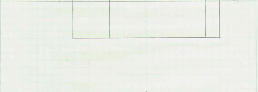
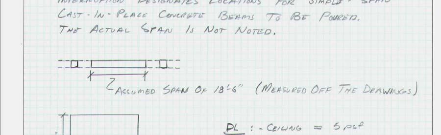
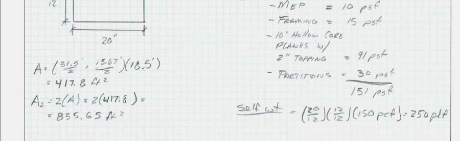
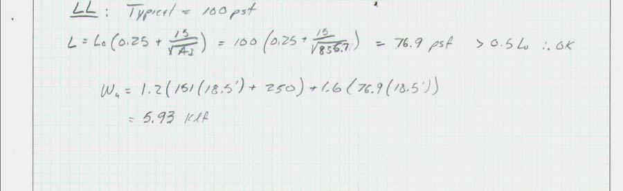
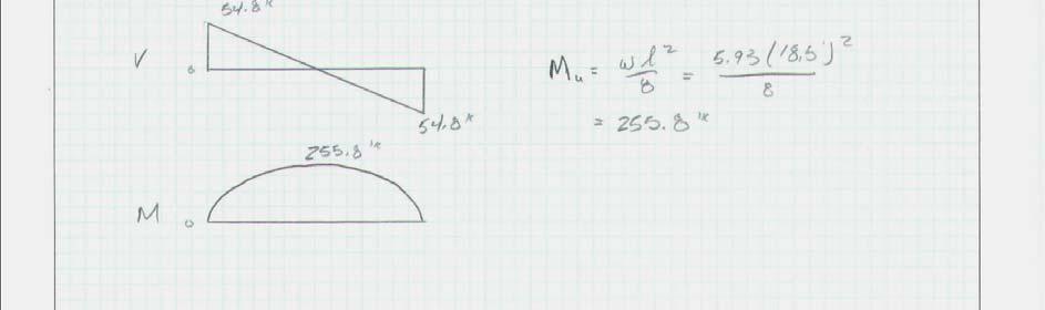
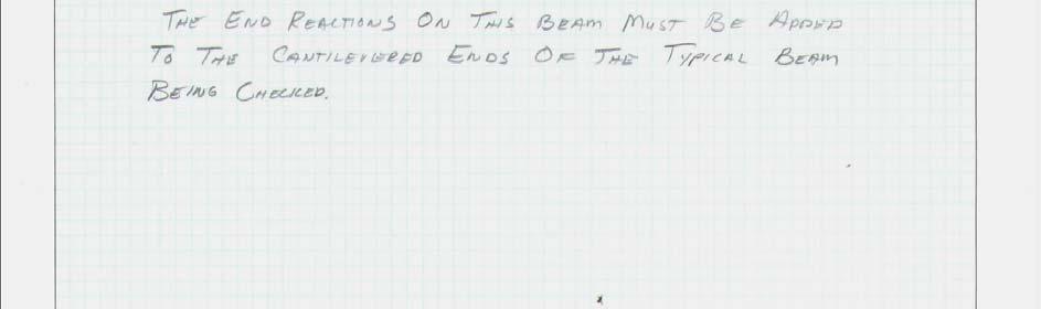
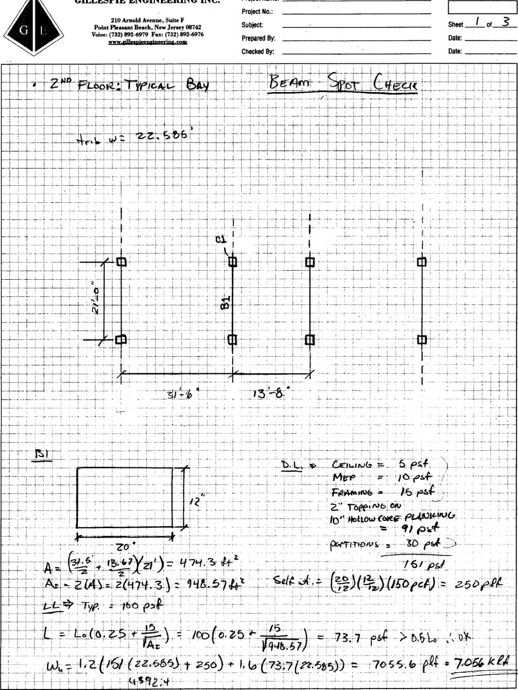
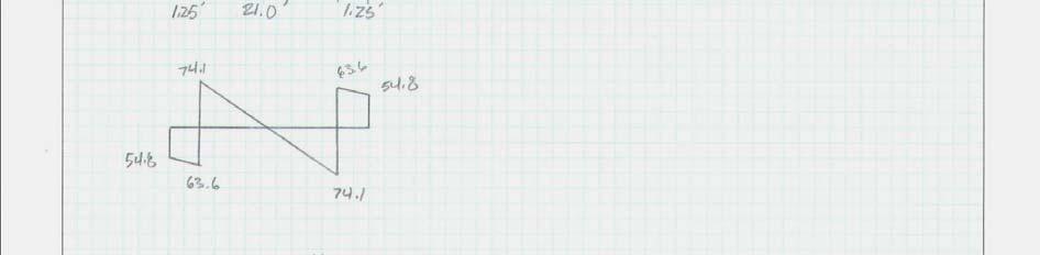
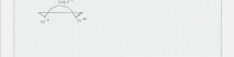
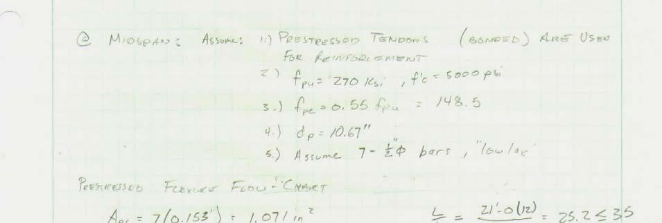
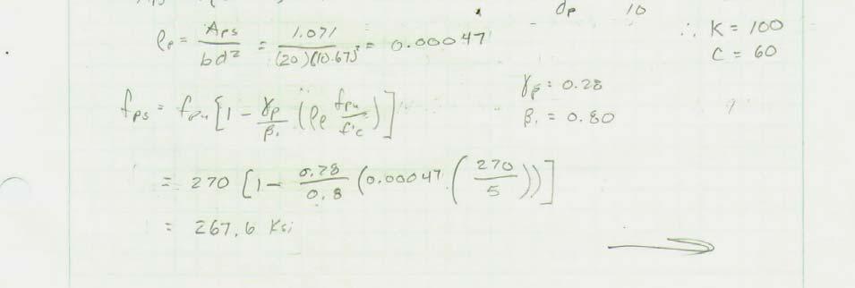
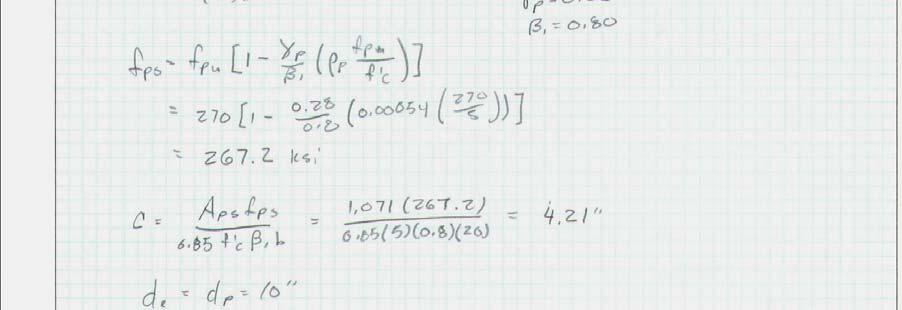
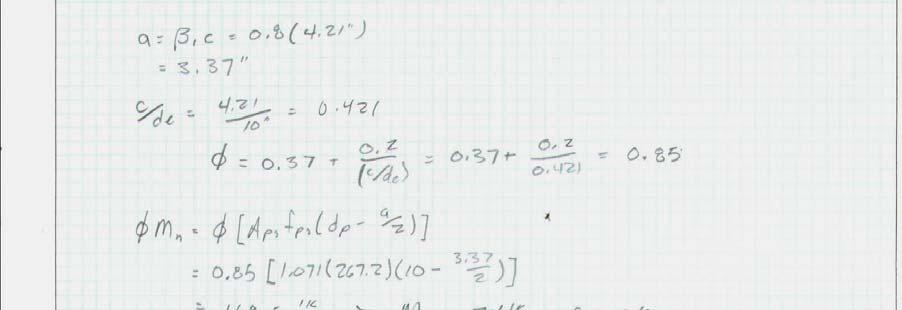
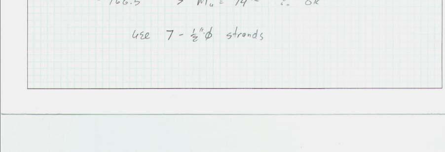
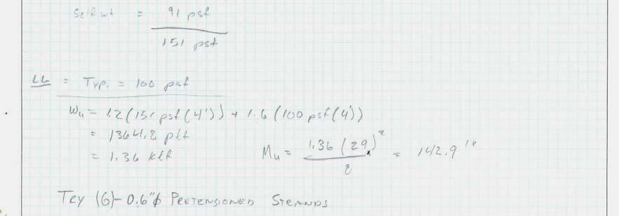
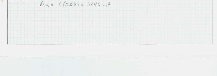
6 precast panels as well as the precast stairs are heavily reinforced. The stairs are cantilevered out of the exterior wall as they spiral upward. The other means of egress are the elevators where the shafts are framed out with 8 CMU block. In addition to the CMU elevator shaft, the elevator and stairwell located in the West Wing are framed out with steel beams of sizes W10x12 and W12x16 predominantly. Roof The roof to the KINSC is framed with structural steel members. The columns supporting the bent-frame steel roof are standard W-shape steel columns consisting of W10x30, W10x33, and W10x45 in size. These columns are positioned directly above the precast concrete columns on the floors below. On the East Wing, the framing between the bentframes are typically W14x22 members on the exterior spans with W12x22 and W12x26 members spanning the long direction of the building in the interior span. The most typically bent-frame is comprised of W14x34 members, both angled and horizontal. The other bent-frames on the East Wing are constructed with members that are very similar in size and weight to this bent-frame. As for the West Wing, the roof framing is similar. The steel members framing between the bent-frames are typically W14x22 members for the exterior spans with W12x16 members spanning the long direction of the building for the interior spans. The steel beams that run along the exterior walls at both wings are sized at W16x50. Spot Check Results Beams A typical precast concrete beam from the first floor in the East Wing was chosen for the spot check. From the drawings, it appears that the interior beams spanning the length of the building are cantilevered and have several typical interruptions that occur between spans. Since the floor layout still requires support where these interruptions take place, the assumption made is that the interruption in the beam span is a designation for a castin-place concrete simple span beam. Assuming this is the case, the reactions from the simple beam were applied to the cantilevered portion of the precast beam to account for the balancing of flexural moments. The precast beam has a center span of 21 and has a cantilever on each side. The length of the cantilever is not shown, therefore it was measured by scale of the drawing to be 1-3. The reinforcement in the beam is unknown. Therefore the results from the analysis could not be checked for result accuracy. For the entire set of calculations, see Appendix A 20 x12 precast concrete beam Center span of 21-0, cantilever of 1-3 on each side Reaction from simple span C.I.P. beam: P = 54.8 k Calculated distributed load: wu = klf Reactions at supports: P = midspan: o M u = k 6
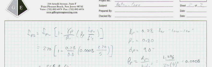
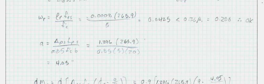
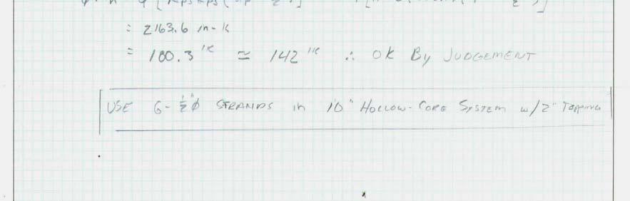
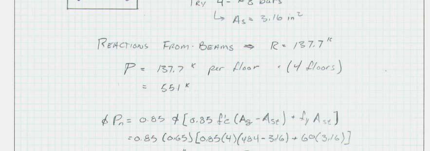
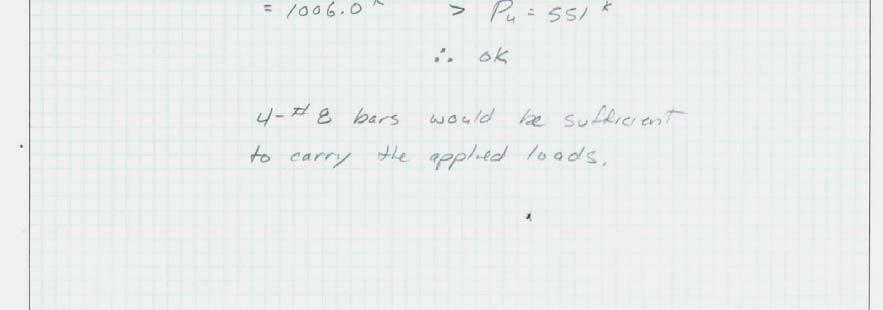
7 o Required tension steel: 2 layers of dia. strands; As = 3.03 sq. in. o Required compression steel: 6 - #11 bars; As = 9.36 sq. in. o ΦM n = k > M u OK for supports: o M u = 74 k o Required tension steel: 7 ½ dia. strands; As = 1.07 sq. in. o ΦM n = 168 k > M u OK for flexure Hollow Core Plank Floor System The typical flooring for the KINSC was designed to be a 10 hollow core plank system with 2 topping. However, no reinforcement of the hollow core planks were provided in the drawings that were available for review, therefore some assumptions had to be made. Also, it was noted in the drawings that SpanDeck is the type of hollow core planks used. However, while referencing the PCI Manual for the Design of Hollow Core Slabs, a 10 section could not be found from SpanDeck, therefore, a 10 section with 2 topping from Dy-Core was used as a similar section. For entire calculations, see Appendix B. 10 hollow core planks w/2 topping Assume 4 panels Span = 31-5 w u = 1.2(DL) + 1.6(LL) = 1.36 klf Assume simple span: M u = (w u *l2)/8 = k Use dia. prestressed tendons ΦM n = k > M u = k OK for flexure Columns The typical interior precast concrete column supporting the interior precast beam that was checked, located on the first floor, was chosen for a spot check. Although the column is dimensioned as 22 x22 with a height of 13, no steel reinforcement was shown in the drawings provided. Therefore, an assumption had to be made. The load is acting at the center of the column cross section, therefore there is no eccentricity causing any moment in the column. It was assumed that the reinforcement in the column consisted of 4 - #8 bars giving an area of steel of 3.16 square inches. Dimensions: 22 square column Span: 13 floor to floor Assume 4 - #8 bars for reinforcement; As = 3.16 sq. in. Reaction from Beam Check: P = kips (per floor) Total Axial Load: P u = 551 k ΦPn = 1006 k; Design is sufficient The reason for the over-designing of the column may be due to the limited deflection that is allowed for the concrete column for story drift before the concrete cracks. Another 7
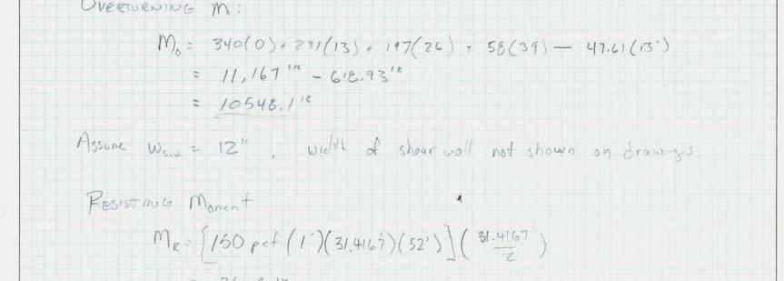
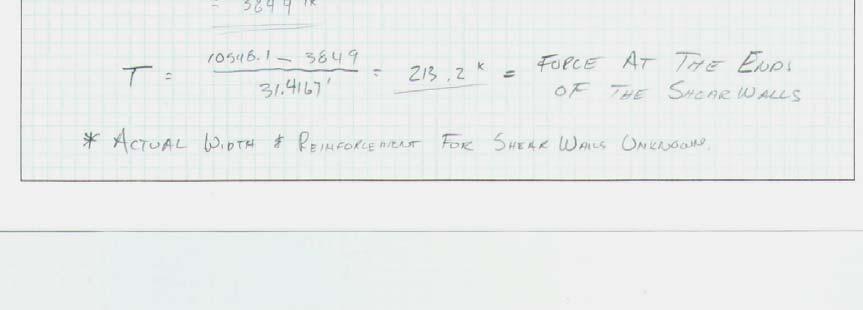
8 reason could be for connection purposes, providing a better fit for beams to columns. See Appendix C for calculations. Shear Wall The design of the KINSC incorporates the use of precast concrete shear walls to resist the lateral forces acting on the structure. Shear walls are located on every floor of the building. A shear wall in the East Wing at the southern end of the building was chosen to be checked. The thickness and reinforcement of the shear wall is unknown. It was assumed to be 12 thick. Tributary areas were used to dissipate the lateral loads to each of the resisting shear walls. It was found that the shear wall requires hold downs to resist a force of 213 kips. See Appendix D for entire calculations. Tributary width: 73-3 Lateral forces o Roof 58 k o 4 th floor 197 k o 3 rd floor 291 k o 2 nd floor 340 k M OT = k M R = 3899 k T = 213 k Load Design Wind vs. Seismic The following tables show the findings from the wind analysis and seismic analysis of the 4-story KINSC, as per ASCE The lateral force resisting system in the building is comprised of shear walls that have the same tributary area, whether dealing with wind or seismic loading. With this in consideration, and with the results from the tables below, it was concluded that the seismic loading was the controlling lateral force for the building. The following tables/diagrams: Wind factors and tabulations Wind loading diagrams Seismic factors and tabulations Seismic loading diagrams 8
9 Wind ASCE 7 02 Sec. 6 Wind Analysis Simplified Method - ASCE 7-02 Sec. 6.4 Wind Load Factors mean building height (must be < 60'): h (ft.) = From General Notes on Plans Basic Wind Speed: V (mph) = 75 Building Category: Category III Table 1-1 Importance Factor: I = 1.15 Table 6-1 Exposure Category: Category B Sec Ht.& Exposure Adjustment Coeff.: λ = Fig. 6-2; by interpolation Zone p s30 A 11.5 p s = λ*i*p s30 B -5.9 Horizontal C 7.6 Pressures I = 1.15 D -3.5 p s30 = (-5.9) E λ: see below F -7.8 Vertical G -9.6 Pressure H -6.1 height λ I p s = λ*i*p s30 (psf) Level plf of width Roof th rd nd st Basement


10 East Wing & Link: Wind Loads (psf) Controlling Direction 10


11 East Wing & Link: Concentrated Wind Loads in Controlling Direction 11


12 West Wing: Wind Loads (psf) Controlling Direction 12
13 Seismic ASCE 7 02 Sec. 9: Building Information Haverford, Building Location PA # of stories 4 inner story ht. 13 Bldg. height 53 Seismic Use Group III Importance Factor 1.15 Site Classification B 0.2s Acceleration s Acceleration 0.08 Site Class Factor: F a 1.00 F v 1.00 Adjusted Accelerations S ms 0.35 Spectral Response Accelerations Seismic Design Category S m S DS S D B Seismic Analysis East Wing & Link Vertical Distribution of Seismic Forces (N-S) k N-S = 1+ (T N-S - 0.5)/( ) = Level, x w x h x k w x h x C vx F x V x M x (kips) (ft.) (kips) (kips) (ft-kips) Roof Σ= Σ= Σ= Σ= Σ=
14 Vertical Distribution of Seismic Forces (E-W) k E-W = 1+ (T E -W 0.5)/( ) = Level, x w x h x k w x h x C vx F x V x M x (kips) (ft.) (kips) (kips) (ft-kips) Roof Σ= Σ= Σ= Σ= Σ= West Wing Vertical Distribution of Seismic Forces (N-S) k N-S = 1+ (T N-S - 0.5)/( ) = Level, x w x h x w x h x k C vx F x V x M x (kips) (ft.) (kips) (kips) (ft-kips) Roof Σ= Σ= Σ= Σ= Σ= Vertical Distribution of Seismic Forces (E-W) k E-W = 1+ (T E -W 0.5)/( ) = Level, x w x h x k w x h x C vx F x V x M x (kips) (ft.) (kips) (kips) (ft-kips) Roof Σ= Σ= Σ= Σ= Σ=
15 Snow Loads Snow Loads ASCE 7-02 Sec. 7.3 Snow Load Analysis Flat Roof Snow Loads - ASCE 7-02 Sec. 7-3 p f = 0.7*C e *C t *I*p g p f,min = 20*I (For p g > 20 psf) p g (psf) = 30 (As per General Notes; see structural dwgs.) C e = 0.7 (As per General Notes; see structural dwgs.) C t = 1 (Table 7-3) I = 1 (As per General Notes; see structural dwgs.) <= p f (psf) = 14.7 p f,min (psf) = 20 *Controls* 15
16 Appendix A Beam Spot Check 16

17 Precast Concrete Beam 17


18 Precast Concrete Beam 18
19 19

20 Precast Concrete Beam 20
21 Precast Concrete Beam 21
22 22
23 Appendix B Floor System Spot Check 23


24 Hollow Core Plank System 24

25 25
26 Appendix C Precast Concrete Column Check 26


27 Precast Concrete Column 27
28 Appendix D Shear Wall Check 28


29 Precast Concrete Shear Wall 29
30 Appendix E Building Sketches 30
31 Building Plan Controlling Wind Direction Controlling Wind Direction Spot Check Locations Building Section West Wing 31
32 Beam B1/ Column C1/Shear Wall Spot Check Locations C1 Shear Wall 32
Structural Technical Report 1 Structural Concepts / Structural Existing Conditions Report
 Michael A. Troxell Structural Option Advisor: Professor Parfitt College of Business Administration Oct. 5, 2005 Structural Technical Report 1 Structural Concepts / Structural Existing Conditions Report
Structural System. Design Criteria Fire Resistance Concrete designed for 2 HR rating (worst case) Geotechnical Report Allowable Bearing Capacity
 Geotechnical Report Allowable Bearing Capacity") System Codes and Criteria Design Codes and Standards The design code used is the Wisconsin Administrative Code along with the State of Wisconsin Department of Commerce-Safety & Buildings Chapters Comm
System Codes and Criteria Design Codes and Standards The design code used is the Wisconsin Administrative Code along with the State of Wisconsin Department of Commerce-Safety & Buildings Chapters Comm
Weill Cornell Medical Research Building 413 E. 69 th Street New York, NY
 Weill Cornell Medical Research Building 413 E. 69 th Street New York, NY Structural Option Technical Report 1 9/23/11 Table of Contents Executive Summary..3 Introduction.4 Structural Systems...5 Foundation
North Mountain IMS Medical Office Building
 North Mountain IMS Medical Office Building Phoenix, Arizona Michael Hopple Technical Assignment 2 October 29 th, 2007 AE 481W-Senior Thesis The Pennsylvania State University Faculty Adviser: Dr. Ali Memari,
Table of Contents.2. Introduction...3 Gravity Loading and Deflections..4. Existing Structural System..8
 WISCONSIN PLACE RESIDENTIAL TECHNICAL ASSIGNMENT 2 OCTOBER 29, 2007 KURT KRASAVAGE THE PENNSYLVANIA STATE UNIVERSITY STRUCTURAL OPTION FACULTY ADVISOR: DR. ALI MEMARI 1 Table of Contents Table of Contents.2
Structural Technical Report #2 Pro/Con Study of Alternate Floor Systems
 Christopher McCune Structural Option Eight Tower Bridge Faculty Advisor: Dr. Hanagan October 31 st, 2005 Structural Technical Report #2 Pro/Con Study of Alternate Floor Systems Executive Summary This technical
The Structural Redesign of Boyds Bear Country and its Related Systems. Boyds Bear Country, Pigeon Forge, Tennessee
 The Structural Redesign of Boyds Bear Country and its Related Systems Included in this Presentation: Background and Existing System Proposal Problem / Solution Structural System Redesigns Pre-cast Concrete
Structural Redesign Gravity System
 Redesign Gravity System Design Considerations A composite floor system was used for this design to maximize the efficiency of the material being used. This type of system requires less material and provides
PricewaterhouseCoopers Building Oslo, Norway
 PricewaterhouseCoopers Building Oslo, Norway James Wilson Structural Option Senior Thesis Presentation 2009 The Pennsylvania State University Location Bjørvika B10 A Oslo, Norway BARCODE Building Data
Global Village Rochester Institute of Technology Rochester, New York
 Presentation Outline Welcome Introduction Architecture Existing Structure Problem Statement Arch. Breadth Structural Depth Conclusion Questions Global Village Rochester Institute of Technology Rochester,
North Mountain IMS Medical Office Building
 North Mountain IMS Medical Office Building Phoenix, Arizona Michael Hopple Technical Assignment 1 October 5 th, 2007 AE 481W-Senior Thesis The Pennsylvania State University Faculty Adviser: Dr. Ali Memari,
Technical Assignment 1 10/8/03
 Executive Summary Technical Assignment 1 10/8/03 The is 55 story high-rise condominium being built off the northern Miami coast. The structural design presented in this building is a direct result of its
CVEN 483. Structural System Overview
 CVEN 483 Structural System Overview Dr. J. Bracci Fall 2001 Semester Presentation Overview 1. Building system primary function 2. Types of load 3. Building materials 4. Structural members 5. Structural
AISC Steel & Timber Research for High-Rise Residential Buildings
 AISC Steel & Timber Research for High-Rise Residential Buildings Final Report December 4 th, 2017 SOM Designed Benchmark Concrete Building Skidmore, Owings, and Merrill, LLP 2017 224s Michigan Avenue Suite
HOTEL NORTHEAST U.S. JORDAN RUTHERFORD STRUCTURAL OPTION FACULTY ADVISOR DR. THOMAS BOOTHBY AE SENIOR THESIS APRIL 8, 2013
 HOTEL NORTHEAST U.S. JORDAN RUTHERFORD STRUCTURAL OPTION FACULTY ADVISOR DR. THOMAS BOOTHBY AE SENIOR THESIS APRIL 8, 2013 HOTEL N.E.U.S. BUILDING INFORMATION SITE Located in the Northeast United States
151 First Side. Technical Assignment 2 November 16 th, William J. Buchko. AE 481w Senior Thesis The Pennsylvania State University
 November 16 th, 2007 William J. Buchko AE 481w Senior Thesis The Pennsylvania State University Thesis Advisor: Kevin Parfitt Table of Contents Executive Summary... 3 Structural System Overview Foundation...
Nasser Marafi. Alternate Floor Systems. Pro Con Structural Study of. Technical Report 2. Center & Facility Service Building
 Pro Con Structural Study of Alternate Floor Systems St. Joseph Hospital of Orange Patient Care Center & Facility Service Building Technical Report 2 Professor Andres Lepage STRUCTURAL OPTION October 26th
Spring Hill Suites Marriott
 Spring Hill Suites Marriott Project Location: Amarillo, TX Prepared for: Girder Slab Technologies Contact: Daniel Fisher, Sr. January 15, 2008 Prepared by: Monica Stockmann Regional Engineer: Erika Winters-Downey
Structural Technical Report #1 By Robert Whitaker
 Structural Technical Report #1 By Robert Whitaker Robert Whitaker Structural ~ Parfitt Parkview at Bloomfield Station Bloomfield, NJ 10-05-05 Executive summary This report covers the structural concepts
MEMORIAL SLOAN-KETTERING CANCER CENTER
 MEMORIAL SLOAN-KETTERING CANCER CENTER SENIOR THESIS PRESENTATION THE PENNSLYVANIA STATE UNIVERSITY DEPARTMENT OF ARCHITECTURAL ENGINEERING PRESENTATION OUTLINE INTRODUCTION BUILDING DESCRIPTION EXISTING
Structural Option April 7 th, 2010
 Gravity System (Depth Topic I) Post Tensioned Slab A new floor system was designed in an attempt to create a more consistent flooring system throughout the entire building. This new design consists of
LIFE SCIENCES BUILDING STRUCTURAL CONCEPTS AND EXISTING CONDITIONS
 Structural Technical Report 1 LIFE SCIENCES BUILDING STRUCTURAL CONCEPTS AND EXISTING CONDITIONS Prepared for: Dr. Aly M. Said Dr. Thomas Boothby Professor Kevin Parfitt Dr. Charles D. Cox Prepared by:
MITRE 3 Building McLean VA
 Executive Summary: The MITRE 3 building is an eight story office building. Its current frame is composed of A992 wide flange shapes. The lateral resisting system is a moment frame. This moment frame consists
Technical Report 3. Alyssa Stangl Structural Option Advisor Dr. Linda Hanagan L A J O L L A C O M M O N S P H A S E I I O F F I C E T O W E R
 Technical Report 3 Alyssa Stangl Structural Option Advisor Dr. Linda Hanagan L A J O L L A C O M M O N S P H A S E I I O F F I C E T O W E R Site and Location La Jolla Commons, San Diego, California General
CE 3150 Reinforced Concrete Design Design Project
 Problem Description For this design project you will work in your project groups to complete a partial design of an office building. Specifically, you will design and fully detail three components: 1.
Brent Ellmann Structural Option 200 Minuteman Park, Andover, MA Structural Consultant: Dr. Hanagan
 Executive Summary: 200 Minuteman Park currently stands as a three story commercial building. The original design was limited to three stories by an industrial zoning law in Andover, Massachusetts. If this
Johns Hopkins Graduate Student Housing. Thesis Proposal. 929 North Wolfe Street Baltimore, Maryland Brad Oliver Structural Advisor: Professor Memari
 Johns Hopkins Graduate Student Housing 929 North Wolfe Street Brad Oliver Structural Advisor: Professor Memari 12/09/2011 Table of Contents Executive Summary -... 3 Introduction... 4 Structural Systems...
Structural Comparison between Pan Joist Concrete and Steel Frame Systems for UMCP Student Housing Building B
 Structural Comparison between Pan Joist Concrete and Steel Frame Systems for UMCP Student Housing Executive Summary The proposed thesis will include an investigation of two different alternative structural
Proposal. PricewaterhouseCoopers Oslo, Norway
 Proposal James Wilson Structural Option AE 481W Senior Thesis The Pennsylvania State University Faculty Consultant: Professor M. Kevin Parfitt Table of Contents Executive Summary...2 1. Existing Conditions...3
EMERGENCY MANAGEMENT PREPAREDNESS AND ASSISTANCE TRUST FUND ARC 4496 Evaluation Questionnaire
 EMERGENCY MANAGEMENT PREPAREDNESS AND ASSISTANCE TRUST FUND ARC 4496 Evaluation Questionnaire Additional Instructions and Clarifications 1. Please review ARC 4496 before beginning the project identification
Design Example 2 Reinforced Concrete Wall with Coupling Beams
 Design Example 2 Reinforced Concrete Wall with Coupling Beams OVERVIEW The structure in this design example is a six story office building with reinforced concrete walls as its seismic force resisting
Eric Alwine Structural Option George Read Hall The University of Delaware Dr. Boothby Technical Assignment #2 October 31, 2005 EXECUTIVE SUMMARY:
 EXECUTIVE SUMMARY: THIS REPORT IS A COMPARISON OF ALTERNATE FLOOR SYSTEMS FOR GEORGE READ HALL. FOUR DIFFERENT SYSTEMS WERE DESIGNED AND COMPARED TO THE EXISTING HAMBRO FLOOR SYSTEM. THE FOUR SYSTEMS WERE
Fundamentals of Post Tensioned Concrete Design for Buildings
 Fundamentals of Post Tensioned Concrete Design for Buildings Part Three by John P. Miller Overview of This Course This is Part Two of a two-part course that covers the fundamentals of post-tensioned concrete
Suspended Metal lath and Cement Plaster. Coverings Rigid Insulation, 1/2 - in 0.75 psf. Floor Fill Lightweight Concrete, per inch 8 psf
 Dead Loads Ceiling Suspended Metal lath and Cement Plaster 15 psf Coverings Rigid Insulation, 1/2 - in 0.75 psf Floor Fill Lightweight Concrete, per inch 8 psf Floor Finish Frame Partitions Ceramic or
NATIONAL HARBOR BUILDING M OXON HILL, MARYLAND. Ryan Sarazen Structural Option Technical Report 3 Faculty Consultant: Dr.
 NATIONAL HARBOR BUILDING M OXON HILL, MARYLAND Ryan Sarazen Structural Option Technical Report 3 Faculty Consultant: Dr. Andres Lepage Table of Contents Executive Summary.. 3 Structural Systems Overview...
REINFORCING TABLES INSTALLATION MANUAL
 REINFORCING TABLES 201 REINFORCING TABLES Design Limitations Introduction The structural wall reinforcing and lintel design tables contained within the Appendix of NUDURA s Installation Manual have been
CHAPTER 2: CONCRETE POST-TENSIONED REDESIGN
 CHAPTER 2: CONCRETE POST-TENSIONED REDESIGN 2.1 INTRODUCTION The basis for the structural depth of this report was a switch from composite steel beam and concrete floor system to a concrete post-tensioned
Strength Design of Reinforced Concrete Structures
 Chapter 6 Strength Design of Reinforced Concrete Structures 6.1 Analysis and Design General Considerations 6.1.1 Convention and Notation Unless otherwise explicitly stated, the following units shall be
January 14, 2006 Structural Thesis Proposal: Structural and Breadth Redesign Options
 River Tower at Christina Landing Wilmington, DE Joseph Bednarz Structural Option Faculty Advisor: Dr. Boothby Executive Summary January 14, 2006 Structural Thesis Proposal: Structural and Breadth Redesign
One-Way Wide Module Joist Concrete Floor Design
 One-Way Wide Module Joist Concrete Floor Design A 1 3 4 30'-0" 30'-0" 30'-0" 3' B 3' C 3' D 3' E 4" 4" (typ.) 3' F 0" 0" (typ.) Figure 1 One-Way Wide Module Joist Concrete Floor Framing System 1 Overview
Corporate Headquarters
 Great Lakes Region, USA AE Senior Thesis April 13 th, 2015 Mary Julia Haverty Structural Option Advisor H. Sustersic Image Courtesy: RTKL Building Height: 83.33 Cost: Withheld at owner s request Project
Structural Technical Report 3 Lateral System Analysis and Confirmation Design
 Structural Technical Report 3 Lateral System Analysis and Confirmation Design James Wilson Structural Option AE 481W Senior Thesis The Pennsylvania State University Faculty Consultant: Professor M. Kevin
Structural Technical Report #2 By Robert Whitaker
 Structural Technical Report #2 By Robert Whitaker Robert Whitaker Structural ~ Parfitt Parkview at Bloomfield Station Bloomfield, NJ 10-31-05 Executive Summary This report covers the comparative redesign
Executive Summary Thesis Proposal
 Executive Summary Thesis Proposal The Renick Education Building located on campus at North Carolina A&T State University in Greensboro, NC is a braced frame steel structure with concrete shear walls. The
REINFORCED CONCRETE WALL BOUNDARY ELEMENT LONGITUDINAL REINFORCING TERMINATION
 1NCEE Tenth U.S. National Conference on Earthquake Engineering Frontiers of Earthquake Engineering July 1-, 1 Anchorage, Alaska REINFORCED CONCRETE WALL BOUNDARY ELEMENT LONGITUDINAL REINFORCING TERMINATION
Shear Wall Analysis. Introduction. The Medical Office Building Malvern, PA 7
 The Medical Office Building Malvern, PA 7 Shear Wall Analysis Introduction The current lateral system in the Medical Office Building consists of cast-in-place (CIP) concrete moment frames and torsion beams.
ADAPT-PTRC 2016 Getting Started Tutorial ADAPT-PT mode
 ADAPT-PTRC 2016 Getting Started Tutorial ADAPT-PT mode Update: August 2016 Copyright ADAPT Corporation all rights reserved ADAPT-PT/RC 2016-Tutorial- 1 This ADAPT-PTRC 2016 Getting Started Tutorial is
John Hopkins Graduate Student Housing. Technical Report North Wolfe Street Baltimore, Maryland Brad Oliver Structural Advisor: Professor Memari
 John Hopkins Graduate Student Housing 929 North Wolfe Street Brad Oliver Structural Advisor: Professor Memari 10/19/2011 Table of Contents Executive Summary -... 3 Introduction... 4 Structural Systems...
3.5 Tier 1 Analysis Overview Seismic Shear Forces
 Chapter 3.0 - Screening Phase (Tier ) 3.5 Tier Analysis 3.5. Overview Analyses performed as part of Tier of the Evaluation Process are limited to Quick Checks. Quick Checks shall be used to calculate the
Structural Inspection
 General: Background: An inspection and structural analysis have been performed for the purpose of evaluating the buildings structural systems and components. A full set of structural drawings was utilized
Totaling approximately 617,000
 Totaling approximately 617,000 sq. ft, the mixed-use Embassy Suites hotel development is among the largest of several newly built hotels in the business district adjoining New York s bustling Wall Street
TECHNICAL REPORT 2 BUILDING CODES, SPECIFICATIONS, AND LOADS
 TECHNICAL REPORT 2 BUILDING CODES, SPECIFICATIONS, AND LOADS SECOND & STATE BUILDING HARRISBURG PA JADOT A MOOSMAN STRUCTURAL OPTION Primary AE Faculty Consultant... Dr. Thomas E. Boothby Date of Submission...
Anchor bolts ASTM F1554, Gr. 36 Wide flange beams ASTM A992, Fy = 50 ksi Misc. structural steel ASTM A36, Fy = 36 ksi
 STRUCTURAL NOTES MATERIAL STRENGTHS Structural Steel Reinforcing Steel Concrete Masonry Structural Lumber Anchor bolts ASTM F1554, Gr. 36 Wide flange beams ASTM A992, Fy = 50 ksi Misc. structural steel
Loads and Load Paths. "Architecture is inhabited sculpture." -Constantin Brancusi
 Loads and Load Paths "Architecture is inhabited sculpture." -Constantin Brancusi Loads and Load Paths Structural Design Design Loads Dead Load Live Load Snow Load Lateral Loads Load Types Load Combinations
Site Analysis. Site Conditions: Seismic Challenges Strong Winds Average Temperature 69. San Francisco
 A Site Analysis Site Conditions: Seismic Challenges Strong Winds Average Temperature 69 San Francisco A Site Analysis A Engineering School of San Francisco Requirements 2015 Innovative Design Gold LEED
SJI Code of Standard Practice
 Standard Practice CODE OF STANDARD PRACTICE FOR STEEL JOISTS AND JOIST GIRDERS SECTION 1 GENERAL 1.1 SCOPE Adopted by the Steel Joist Institute April 7, 1931 Revised to May 18, 2010 - Effective December
SJI Updates Expanded Load Tables for Noncomposite Joists / Joist Girders and Development of New Composite Joist Series
 SJI Updates Expanded Load Tables for Noncomposite Joists / Joist Girders and Development of New Composite Joist Series SUMMARY David Samuelson Steel joists are growing in recognition as being a very economical
DIVISION: METALS SECTION: STEEL DECKING REPORT HOLDER: EPIC METALS CORPORATION 11 TALBOT AVENUE RANKIN, PENNSYLVANIA 15104
 0 Most Widely Accepted and Trusted ICC ES Evaluation Report ICC ES 000 (800) 423 6587 (562) 699 0543 www.icc es.org ESR 2047 Reissued 07/207 This report is subject to renewal 07/209. DIVISION: 05 00 00
4.2 Tier 2 Analysis General Analysis Procedures for LSP & LDP
 4.2 Tier 2 Analysis 4.2.1 General Four analysis procedures are provided in this section: Linear Static Procedure (LSP), Linear Dynamic Procedure (LDP), Special Procedure, and Procedure for Nonstructural
Massachusetts General Hospital - Building for the Third Century Lateral System Analysis and Confirmation Design
 Massachusetts General Hospital - Building for the Third Century Lateral System Analysis and Confirmation Design 55 Fruit Street 02114 The Pennsylvania State University Department of Architectural Engineering
A Guide for the Interpretation of Structural Design Options for Residential Concrete Structures
 CFA Technical Note: 008-2010 A Guide for the Interpretation of Structural Design Options for Residential Concrete Structures CFA Technical This CFA Technical Note is intended to serve as a guide to assist
Kiski Area High School Allegheny Township, PA FLOOR SYSTEM ANALYSIS
 FLOOR SYSTEM ANALYSIS Objective The objective of the following breadth study is to determine if an alternative floor system for Building N would be more advantageous than the existing floor system. The
Hilton Baltimore Convention Center Hotel Western Podium
 Hilton Baltimore Convention Center Hotel Western Podium CHRIS SIMMONS Structural Option Faculty Consultant: Dr. Ali M. Memari Thesis Proposal TABLE OF CONTENTS EXECUTIVE SUMMARY. Page 3 INTRODUCTION..
A Composite Structural Steel and Prestressed Concrete Beam for Building Floor Systems
 University of Nebraska - Lincoln DigitalCommons@University of Nebraska - Lincoln Architectural Engineering -- Dissertations and Student Research Architectural Engineering Spring 4-20-2012 A Composite Structural
SEAU 5 th Annual Education Conference 1. ASCE Concrete Provisions. Concrete Provisions. Concrete Strengths. Robert Pekelnicky, PE, SE
 ASCE 41-13 Concrete Provisions Robert Pekelnicky, PE, SE Principal, Degenkolb Engineers Chair, ASCE 41 Committee* *The view expressed represent those of the author, not the standard s committee as a whole.
ECMC Skilled Nursing Facility Architectural Engineering Senior Thesis AE 481W Thesis Proposal Dr. Ali Memari January 13 th, 2012
 ECMC Skilled Nursing Facility Architectural Engineering Senior Thesis 2011 Class: Subject: Faculty Consultant: Submitted: AE 481W Thesis Proposal Dr. Ali Memari January 13 th, 2012 Table of Contents Executive
Copyright. magazine. CFS Load Bearing Construction
 Progressive Collapse Requirements Cold-Formed Steel Load Bearing Construction By Nabil A. Rahman, Ph.D., P.E., Michael Booth and Gary Bennett Figure 1: Cold formed steel load bearing mid-rise construction.
CHAPTER 9 STAIR CASES 9.1 GENERAL FEATURES 9.2 TYPES OF STAIR CASES
 CHAPTER 9 STAIR CASES 9.1 GENERAL FEATURES Stair cases are provided for connecting successive floors. It is comprised with flights of steps with inter mediate landings which provides rest to the user and
Substructure systems, specifically retaining walls
 Design principles of totally prefabricated counterfort retaining wall system compared with existing cast-in-place concrete structures Maen Farhat and Mohsen Issa An alternative to cast-in-place concrete
Project Address: Name of Person Completing Form:
 Statement of Inspections This form is provided as a way to list aspects of the project that require special inspection and testing in accordance with IBC Sections 107.1, 1704, and 1705 and define duties
BACKGROUND: SUBSURFACE CONDITIONS:
 2 BACKGROUND: The planned project consists of a prefabricated modular apartment building with underground parking, located on the site bounded by Dexter Avenue N. to the east, multi-story residential/commercial
Section A A: Slab & Beam Elevation
 CE 331, Spring 2011 Flexure Strength of Reinforced Concrete s 1 / 5 A typical reinforced concrete floor system is shown in the sketches below. The floor is supported by the beams, which in turn are supported
Lateral Design of Mid- Rise Wood Structures
 Lateral Design of Mid- Rise Wood Structures Presented by Ricky McLain, MS, PE, SE Technical Director WoodWorks Texas Workshops December, 2016 Insert picture of me graduating college Follow the load Following
Michael Bologna. 665 Meadow Ln Rochester PA, State College, PA October 16, 2015
 Michael Bologna State College, PA 16801 665 Meadow Ln Rochester PA, 15074 October 16, 2015 Linda M. Hanagan, PhD, P.E. The Pennsylvania State University Dear Dr. Hanagan, The attached technical reports
PEER/CSSC Tall Building Design Case Study Building #1. J. Andrew Fry John Hooper Ron Klemencic Magnusson Klemencic Associates
 PEER/CSSC Tall Building Design Case Study Building #1 J. Andrew Fry John Hooper Ron Klemencic Magnusson Klemencic Associates Building Information Located in Los Angeles 42-Story 410 ft Tall 108 ft X 107
The designer shall also submit additional information required by the University as described and underlined below.
 I. Structural Engineering Submissions The designer shall submit all information required by the State Construction Office (SCO) as described in the State Construction Manual Chapter 300 - Project Design
111 MORGAN ST. CHICAGO, IL
 111 MORGAN ST. CHICAGO, IL Ryan W. Friis Structural Option Spring 2003 Senior Thesis Penn State University Department of Architectural Engineering 111 MORGAN ST. CHICAGO, IL Owner: GC: Architect: Structural:
LATERAL LOAD BEHAVIOR OF UNBONDED POST-TENSIONED HYBRID COUPLED WALLS. Qiang SHEN Graduate Research Assistant. Yahya C. KURAMA Assistant Professor
 LATERAL LOAD BEHAVIOR OF UNBONDED POST-TENSIONED HYBRID COUPLED WALLS Qiang SHEN Graduate Research Assistant Yahya C. KURAMA Assistant Professor University of Notre Dame, Civil Engineering and Geological
Sabah Shawkat Cabinet of Structural Engineering 2017
 3.1-1 Continuous beams Every building, whether it is large or small, must have a structural system capable of carrying all kinds of loads - vertical, horizontal, temperature, etc. In principle, the entire
The Structural Design of Laramie County Community College Student Services Center
 University of Wyoming Wyoming Scholars Repository Honors Theses AY 15/16 Undergraduate Honors Theses Spring 2016 The Structural Design of Laramie County Community College Student Services Center Katie
FDA CDRH Laboratory Silver Spring, Maryland. Executive Summary: Timothy Mueller Structural Option Walter Schneider
 Executive Summary: The FDA-CDRH Laboratory is currently being built on the Food and Drug Administration s White Oak Consolidation Campus. It is a four story building with a full below grade ground floor
Precast Concrete Bearing Wall Panel Design (Alternative Analysis Method) (Using ACI )
 (Using ACI )") Precast Concrete Bearing Wall Panel Design (Alternative Analysis ethod) (Using ACI 318-14) Precast Concrete Bearing Wall Panel Design (Alternative Analysis ethod) (Using ACI 318-14) A structural precast
Precast Concrete Bearing Wall Panel Design (Alternative Analysis ethod) (Using ACI 318-14) Precast Concrete Bearing Wall Panel Design (Alternative Analysis ethod) (Using ACI 318-14) A structural precast
AIA St. Louis January 4 th, 2017 Phillip Shinn, PE Jacobs Engineering Washington University in St. Louis, Sam Fox School of Design and Visual Arts
 AIA St. Louis January 4 th, 2017 Phillip Shinn, PE Jacobs Engineering Washington University in St. Louis, Sam Fox School of Design and Visual Arts Owners are NOT Architects (but they ARE the Owners) Steel
CODE OF STANDARD PRACTICE
 CODE OF STANDARD PRACTICE FOR STEEL JOISTS AND JOIST GIRDERS SECTION 1. GENERAL 1.1 SCOPE Adopted by the Steel Joist Institute April 7, 1931 Revised to Nov. 10, 2014 - Effective Jan.1, 2015 The practices
Thesis Proposal. Nasser Marafi. Center & Facility Service Building. St. Joseph Hospital of Orange Patient Care. Proposal
 St. Joseph Hospital of Orange Patient Care Center & Facility Service Building Proposal Professor Andres Lepage STRUCTURAL OPTION December 17th 2007 Executive Summary Thesis Proposal During the upcoming
Allowable Loads for Round Timber Poles
 UNIVERSITY OF ALASKA FAIRBANKS Allowable Loads for Round Timber Poles HCM-00752 UNIVERSITY OF ALASKA FAIRBANKS The following publication is a major upgrade of information for calculating and understanding
Bjorhovde, R. Stub Girder Floor Systems Structural Engineering Handbook Ed. Chen Wai-Fah Boca Raton: CRC Press LLC, 1999
 Bjorhovde, R. Stub Girder Floor Systems Structural Engineering Handbook Ed. Chen Wai-Fah Boca Raton: CRC Press LLC, 1999 Stub Girder Floor Systems Reidar Bjorhovde Department of Civil and Environmental
DESIGN FOR PROGRESSIVE COLLAPSE 1
 Your Partner in Structural Concrete Design TN447_progressive_collapse_110713 DESIGN FOR PROGRESSIVE COLLAPSE 1 Bijan O Aalami 2 This Technical Note outlines the design of column-supported conventionally
LPI 56 Technical Guide
 LPI 56 Technical Guide Floor & Roof Applications Product Specifications & Design Values 2 Floor Tables 3 Uniform Floor Load (PLF) Tables: Simple s 4 Uniform Floor Load (PLF) Tables: Continuous s 5 Uniform
Structural Tests and Special Inspections Form. Inspection of Fabricators (1704.2)
") Inspection of Fabricators (1704.2) Furnish inspection reports (1704.2.1) - Fabricators that have not been approved Provide a Certificate of Compliance (1704.2.2) - Approved Fabricators Steel Construction
Inspection of Fabricators (1704.2) Furnish inspection reports (1704.2.1) - Fabricators that have not been approved Provide a Certificate of Compliance (1704.2.2) - Approved Fabricators Steel Construction
CIVIL BREADTH Exam Specifications
 NCEES Principles and Practice of Engineering Examination CIVIL BREADTH and STRUCTURAL DEPTH Exam Specifications Effective Beginning with the April 2015 Examinations The civil exam is a breadth and depth
16. Design of Pipeline Structures.
 16. Design of Pipeline Structures. a. General. 1) The following guidelines are for the design of structures for water and sewer pipelines including structural concrete and miscellaneous metals design.
BrD Superstructure Tutorial
 AASHTOWare BrD 6.8 BrD Superstructure Tutorial PS12 Prestressed Concrete I Beam Using BrD LRFD Engine BrD Superstructure Training PS12 - Prestressed Concrete I Beam Using BrD LRFD Engine 1'-9" 55'-6" Total
Council on Tall Buildings
 Structure Design of Sino Steel (Tianjin) International Plaza Xueyi Fu, Group Chief Engineer, China Construction Design International 1 1 Brief of Project 2 Location: Tianjin Xiangluowan Business District
10/23/2011. Plan Examination. Plan ExaminationPurpose. Catch problems in advance of construction.
 Plan Examination 1 Plan ExaminationPurpose 2 Catch problems in advance of construction. 3 1 Discovery of problems in the field results in higher cost. 4 Can a good plan review eliminate all problems in
ALLOWABLE STRESS DESIGN OF CONCRETE MASONRY LINTELS. TEK 17-1C Structural (2009) Related TEK: Uniform load. Triangular load. Concentrated loads
 Related TEK: Uniform load. Triangular load. Concentrated loads") An information series from the national authority on concrete masonry technology ALLOWABLE STRESS DESIGN OF CONCRETE MASONRY LINTELS TEK 17-1C Structural (2009) INTRODUCTION Lintels and beams are horizontal
An information series from the national authority on concrete masonry technology ALLOWABLE STRESS DESIGN OF CONCRETE MASONRY LINTELS TEK 17-1C Structural (2009) INTRODUCTION Lintels and beams are horizontal
Final Report. University of Virginia s College at Wise New Library. Image Courtesy of Cannon Design
 Final Report University of Virginia s College at Wise New Library Image Courtesy of Cannon Design Advisor: Heather Sustersic 9 April 2014 General Information Full Height: 119 Number of Stories: 6 Size:
Embassy Suites Hotel Springfield, Virginia. Dominick Lovallo Structural Option AE Senior Thesis Thesis Advisor: Dr.
 Embassy Suites Hotel Springfield, Virginia Dominick Lovallo Structural Option AE Senior Thesis 2012-2013 Thesis Advisor: Dr. Hanagan Lobby Rendering Presentation Overview Proposed Building Presentation
Effect of Edge Beam and Shear Wall on the Structural Behavior of Flat Plate Multistoried Building: A Computing Modeling for lateral load Analysis
 Effect of Edge Beam and Shear Wall on the Structural Behavior of Flat Plate Multistoried Building: A Computing Modeling for lateral load Analysis Zasiah Tafheem 1, A.S.M Rubaiat Nahid 2, Tanzeelur Rahman