STORMCAPTURE. Installation Manual
|
|
|
- Natalie Malone
- 6 years ago
- Views:
Transcription


1 STORMCAPTURE Installation Manual
2 Introduction Site Preparation Delivery & Installation LinkSlabs Backfill


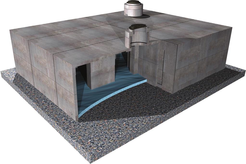
3 Introduction StormCapture (shown in Figure 1) is a total stormwater management system. The highly-configurable module has many solutions for detention, retention, infiltration, treatment and harvesting. Multiple modules can be arranged into endless formations to meet the needs of even the most challenging sites. The rectangular design facilitates rapid and easy installation, plus stress-free maintenance. The precast concrete provides long-term reliability and low lifecycle costs. The engineer of record is responsible for reviewing and approving the system design, storage volume, required depth of cover, vehicular loading, water table elevation, backfill material and soil bearing capacity. Any variations found during construction to those stated on the plans must be reported to the engineer and Oldcastle Precast. This manual is not intended to be all-inclusive and is a reference guide only. FIGURE 1 Detention System Single Module FIGURE 2 StormCapture System During Installation Process
4 Site Preparation TIMING Excavation and subgrade shall be completed prior to StormCapture delivery. EXCAVATION - See Figures 3 & 4 Depth Concrete invert: Depth of fill* + Module outside height + 2 subgrade depth Open bottom: Depth of fill* + Module outside height + subgrade depth** * 6 minimum, 5 maximum, unless otherwise noted ** Subgrade depth determined in accordance with StormCapture Tech Note SC-01 Excavation shall be large enough to allow access around structure for backfilling and compaction equipment. Trench sloping shall follow OSHA requirements. To prevent excessive water pressure build up on the outside of the modules, the site must be prepared and graded for proper drainage around the StormCapture system. Dewatering is required when water level is above bottom of subgrade. SUBGRADE - See Figures 3 & 4 1. Native soil shall be level and compacted adequately to allow for required bearing capacity on design documents. 2. Add 2 of sand for leveling purposes. 3. Geotextile fabric and containment membrane liner. An 8 oz. non-woven geotextile fabric must be used as a separation layer around the StormCapture system. When the project requires a containment membrane liner, a layer of 8 oz. non-woven geotextile fabric must be used on both the inside and outside face of the liner. Install containment membrane liner per manufacturer s recommendations. 4. Aggregate bearing layer - See Figure 3 Open-bottom modules only are required to be placed on a crushed aggregate bearing layer to a depth in accordance with StormCapture Tech Note SC-01. Material shall be clean, durable crushed aggregate compacted as directed by the engineer of record. Oldcastle recommends size 5, 56 or 57 (per ASTM C33). Extend aggregate bearing layer a minimum of 1 around the system perimeter. Aggregate bearing layer must be level and compacted prior to module placement. An 8 oz. non-woven geotextile fabric must be used as a separation layer around the aggregate material and StormCapture system. Note: Further investigation by a geotechnical engineer may be required where there are concerns with seasonally high water table, and/or poor soil conditions such as low allowable bearing capacity, permafrost and seasonal freeze/thaw cycles.

5 FIGURE 3 1-Piece Module - With Liner FIGURE 4 2-Piece Module - With Liner
6 Delivery & Installation StormCapture modules are to be installed in accordance with ASTM C891-90, Installation of Underground Precast Utility Structures. Project plan and specifications must be followed along with any applicable regulations. TIMING Plan for first delivery of StormCapture modules after site preparation is completed. Individual pieces can be installed in as little as 10 minutes. DELIVERY Verify that equipment can handle module weights as noted on construction documents prior to delivery. StormCapture modules will be delivered on flatbed trucks. HANDLING StormCapture modules are lifted by the designed embedded lifers at points provided by Oldcastle (Figure 5). Designed embedded lifters must be used. Use proper rigging to assure all lifters are equally engaged with a minimum 60 angle on slings (Figure 6). Special lifting clutches are required and shall be coordinated with the producing plant. Always follow safety protocols for handling StormCapture modules during installation as illustrated on this page. Never stand under load (Figure 7). Never place hands in the lift gear (Figure 8). Never place hands under load (Figure 9). PLACEMENT Use the plan line, grade and elevations shown on the construction documents to install the modules. The sand bedding or aggregate bearing layer must be level. Modules must be placed as close together as possible with gaps no greater than 3/4. All vertical & top joints shall be covered with an 8 minimum width self-adhesive joint wrap as shown in Figure 10. Horizontal joints between modules or slabs shall be sealed with Conseal CS-102 butyl rubber sealant as shown in Figure 11. Seal pipe penetrations to containment membrane liner with pipe boots per liner manufacturer s recommendations. FIGURE 6 FIGURE 5


7 FIGURE 7 FIGURE 8 FIGURE 9 FIGURE 10 Sealed Joints Between Modules FIGURE 11 Keyways must be free of dirt, rocks and water. Rocks and dirt prevent the vault sections from seating and sealing properly. Remove all protective paper from rubber sealant material. Splice rubber sealant material with a side by side joint, away from corners. Corner splicing will not seal properly.

8 LinkSlab Procedure These procedures reference the diagram below. This diagram is not indicative of all site layouts. Refer to the site plan for the project specific configuration. FIGURE 12 Example Layout

9 LinkSlab Procedure Maintaining proper line and grade is critical to installation. A qualified surveyor on the site with proper equipment is recommended to ensure a square, level and straight layout. Subgrade must be compacted. 1. Start in the corner of the layout and place the first bottom module C1. 2. Place adjacent bottom modules B, B, D, D. Be sure to set the corners square and straight (from C1 up with D modules, and from C1 right with B modules). 3. Where called out on plans, place reinforcement beams between the modules where the LinkSlab will sit (between B and A). Reinforcement beams may not be required at all locations, so refer to the project specific configuration. 4. Place interior modules A, A. Check the distance between pieces when there is a gap for a LinkSlab. Both bottom corners should be between 8 and 8-1 ¼. 5. Place Conseal CS-102 at the horizontal joints. 6. Place top modules (C1, B, B, D, D, A, A). Check the distance between pieces when there is a gap for a LinkSlab. Both top corners should be 8 and 8-1 ¼. 7. Place Conseal CS-102 for the horizontal LinkSlab joints at D, A, A and B. 8. Place the LinkSlab. Ensure that it fits tightly between all adjacent modules. The drop key should fit inside the adjacent modules. Do not allow the LinkSlab to rest on the drop key. Ensure surface contact with the bottom of the LinkSlab and the top of the adjacent modules. Reset adjacent modules as necessary to correct the problem. 9. Continue placing adjacent modules and LinkSlabs. Oldcastle Precast recommends placing each LinkSlab as soon as the supporting modules are in place to ensure proper fit. 10. Continue installation procedure as recommended in the StormCapture Installation Manual. FIGURE 13 LinkSlab Isometric View RECESSED BOTTOM OF LINKSLAB

10 Backfill Once all modules are in place with joints sealed and geotextile fabric wrapped, the StormCapture system shall be inspected by the engineer of record or an accepted representative. Upon approval, backfilling can begin. Do not compact within 6 of module to avoid damaging the system. Care shall be taken during placement of backfill not to displace modules, joint wrap, containment membrane liner or geotextile fabric. Backfilling shall be in 1 lifts with proper compaction between lifts. Typical backfill shall be compacted to 95% standard proctor density or as specified. Expansive soil material shall not be used as backfill around the structure. Compaction shall be adequate to support expected loads on top of the system and surrounding area. Consult with geotechnical engineer for the project. Once installed, StormCapture modules are ready for paving or overburden material (Figure 14). Finished grading, paving and landscaping shall be per construction documents. Construction equipment exceeding design loading shall not be allowed on structure. Consult Oldcastle Precast if unsure. Contact Oldcastle Precast and the engineer of record if the live loads are greater than HS-20. Track vehicles including D-4 type dozers or lighter are permitted. FIGURE 14 Backfill Installation Is Now Complete Project specific conditions may apply. Please refer to design documents for any special circumstances regarding installation or infiltration. Oldcastle Precast is not liable for installation.
11 Preconstruction Meeting Checklist Project Name: Date: Time: Installer Name: Address: Oldcastle Rep: Cover the installation manual Installer has the approved drawings Crane sizing and proper rigging Coordinate with installer to borrow litfing clutches for installation Hole sizing Recommend $1,600 deposit (paid to plant from contractor), with money to be repaid upon return of undamaged clutches. Extra space for liner weld if needed Hole prep (base prep) Liner (if applicable) Extra hands for unrolling liner needed Project date of install: Delivery truck access to the site Will a truck with a sleeper cab fit? Do construction site items need to be moved for access? Timing of trucks Splash pads first Order of modules to install with ease Assume minutes per piece Installing of modules Joint Wrap Other: Signatures: Project Superintendent: Project Foreman: Other: Other:


12 STORMCAPTURE Installation Manual OUR MARKETS BUILDING STRUCTURES COMMUNICATIONS WATER ENERGY TRANSPORTATION
StormTech Construction Guide
 A division of StormTech solid end caps and pre-cored end caps StormTech chambers StormTech manifolds and fittings Acceptable fill materials per Table 1 Woven and non-woven geotextiles 80-7 DC REQUIRED
Uwall UNIVERSAL CONSTRUCTION MANUAL
 Uwall UNIVERSAL Retaining Wall System CONSTRUCTION MANUAL TM President s Letter CSI is a leader in its industry supplying precast infrastructure products throughout New England and beyond since 1972, developing
Redi Rock Specification and Installation Manual
 Redi Rock Specification and Installation Manual 1.0 General Scope This Specification covers the Design, Materials and Installation of Redi Rock modular block Retaining and Freestanding Wall systems as
CONCRETE SEGMENTAL RETAINING WALL SYSTEM
 CONCRETE SEGMENTAL RETAINING WALL SYSTEM PART 1: GENERAL SPECIFICATIONS 1.01 Work Included A. Work shall consist of furnishing and constructing a Rockwood Classic 8, Classic 6 and Legend unit segmental
SECTION UTILITY MANHOLES AND STRUCTURES
 SECTION 33 05 14 UTILITY MANHOLES AND STRUCTURES PART 1 GENERAL 1.1 SUMMARY A. Section Includes: 1. Precast reinforced concrete manholes and structures with tongue-and-groove joints with masonry transition
CONSTRUCTION STANDARDS SECTION CS 3 TRENCH FOUNDATION, BEDDING AND BACKFILL
 CONSTRUCTION STANDARDS SECTION CS 3 TRENCH FOUNDATION, BEDDING AND BACKFILL CS 3-01 GENERAL: A. The foundation, bedding and backfill for all trenches shall conform with the requirements of the City Standard
R-TANK SPECIFICATIONS
 TECHNICAL STORMWATER MANAGEMENT R-TANK SPECIFICATIONS PART 1 GENERAL 1.01 Related Documents A. Drawings, technical specification and general provisions of the Contract as modified herein apply to this
STANDARD SPECIFICATION FOR CRIBLOCK CONCRETE CRIBWALL
 STANDARD SPECIFICATION FOR CRIBLOCK CONCRETE CRIBWALL 1. SCOPE 2. DESIGN 3. MATERIALS 4. CONSTRUCTION 5. METHOD OF MEASUREMENT AND PAYMENT SCOPE This Specification sets out requirements for the design,
SLAB ON GRADE Insul-Joint or Expansion Joint Material as Required by A/E Specifications AquaCheck Liquid Coating 400 (Waterproofing Membrane) with Aqu
 with Aqu") INSTALLATION INSTRUCTIONS Note: The following installation instructions are based off of ASTM E 1643 (Standard Practice for Installation of Water Vapor Retarders Used in Contact with Earth or Granular
INSTALLATION INSTRUCTIONS Note: The following installation instructions are based off of ASTM E 1643 (Standard Practice for Installation of Water Vapor Retarders Used in Contact with Earth or Granular
DIVISION 31 EARTHWORK 2006 Edition, Published January 1, 2006; Division Revision Date: January 31, 2012
 2006 Edition, Published January 1, 2006; Division Revision Date: January 31, 2012 PART FIVE DOCUMENTS FOR SITE AND INFRASTRUCTURE 31 00 00. EARTHWORK 31 10 00. SITE CLEARING.1 STRUCTURE REMOVAL: Include
SPECIFICATIONS FOR PRECAST MODULAR BLOCK RETAINING WALL SYSTEM (revised 5/8/7)
") Page 1 of 7 STONE STRONG SYSTEMS SPECIFICATIONS FOR PRECAST MODULAR BLOCK RETAINING WALL SYSTEM (revised 5/8/7) PART 1: GENERAL 1.01 Description A. Work includes furnishing and installing precast modular
Page 1 of 7 STONE STRONG SYSTEMS SPECIFICATIONS FOR PRECAST MODULAR BLOCK RETAINING WALL SYSTEM (revised 5/8/7) PART 1: GENERAL 1.01 Description A. Work includes furnishing and installing precast modular
PAVING SLABS ON A CONCRETE BASE
 SECTION 32 14 13.16 PAVING SLABS ON A CONCRETE BASE (1995 MasterFormat Section 02784) Note: This guide specification for the U.S. is for paving slabs on a sand bed over concrete for pedestrian applications.
Attachment D-1: Civil/Structural Scope of Work
 Attachment D-1: Civil/Structural Scope of Work Project: Location: Targa Sound Renewable Fuels Project Tacoma, WA Prepared by: NORWEST ENGINEERING Consulting Engineers 4110 N.E. 122 nd Avenue, Portland,
C. Foundation stabilization for pipe and utility structures.
 PART 1 - GENERAL 1.1 SECTION INCLUDES A. Excavating, backfilling, and compacting for utilities, including pipe, structures, and appurtenances. B. Control of water in trenches. C. Foundation stabilization
VERTI-BLOCK - DESIGN MANUAL
 Company Information General Information Verti-Block is the latest innovative forming system from Verti-Crete, LLC. Recognized worldwide for outstanding aesthetics and performance, Verti-Crete s proprietary
B. Subsurface data is available from the Owner. Contractor is urged to carefully analyze the site conditions.
 SECTION 31 23 33 - TRENCHING, BACKFILLING AND COMPACTION PART 1 - GENERAL 1.1 SCOPE A. This Section specifies the requirements for excavating and backfilling for storm sewer, sanitary sewer, water distribution
MACHINE-LAY Installation Manual
 MACHINE-LAY Installation Manual PaveDrain Installation Manual Table of Contents Section 1: Base Preparation (pages 3 6) Section 2: Machine-Lay PaveDrain Blocks (pages 8 11) Section 3: Edge Restraints (pages
A. This Section includes subdrainage systems for foundations and underslab areas. A. Product Data: For each type of drainage panel indicated.
 ZGF Partnership Page 1 of 7 SECTION 33 46 00 - PART 1 - GENERAL 1.1 SUMMARY A. This Section includes subdrainage systems for foundations and underslab areas. 1.2 SUBMITTALS A. Product Data: For each type
DESIGNING AND CONSTRUCTION OF T-WALL RETAINING WALL SYSTEM
 Istanbul Bridge Conference August 11-13, 2014 Istanbul, Turkey DESIGNING AND CONSTRUCTION OF T-WALL RETAINING WALL SYSTEM T. C. NEEL and K.BOZKURT ABSTRACT This work shall consist of the design, manufacture
SEGMENTAL BLOCK RETAINING WALLS. Comply with Division 1 - General Provisions and Covenants, as well as the following:
 SEGMENTAL BLOCK RETAINING WALLS PART 1 - GENERAL 1.01 SECTION INCLUDES Segmental Block Retaining Walls 1.02 DESCRIPTION OF WORK Constructing segmental block retaining walls. 1.03 SUBMITTALS Comply with
Fabrication and Installation Table of Contents
 Fabrication and Installation Table of Contents HDPE AQUASHIELD PRODUCTS 2 Fabrication and Installation 2 System Fabrication 3 Aqua-Swirl Installation 4 Step 1 Excavation and Bedding 4 Step 2 Pipe Connection
SECTION 19 - TRENCH EXCAVATION, BEDDING AND BACKFILL TABLE OF CONTENTS
 SECTION 19 - TRENCH EXCAVATION, BEDDING AND BACKFILL TABLE OF CONTENTS Section Page 19-1 TRENCH EXCAVATION... 19-1 19-1.01 Exploratory Excavation... 19-1 19-1.02 Trench... 19-1 19-1.02.AStorm Drain Pipe...
Rainwater Harvesting Tank
 ESTLISHED IN 1986 Rainwater Harvesting Tank ssembly and Installation Guide www.atlantiscorp.com.au Tank Module ssembly Guide Rainwater Harvesting Tank ssembly & Installation Guide 2 ssemble Matrix Tank
BMP 6.4.4: Infiltration Trench
 BMP 6.4.4: Infiltration Trench An Infiltration Trench is a leaky pipe in a stone filled trench with a level bottom. An Infiltration Trench may be used as part of a larger storm sewer system, such as a
SECTION INTERLOCKING CONCRETE PAVERS
 SECTION 23 14 13 INTERLOCKING CONCRETE PAVERS (1995 MasterFormat Section 02780) Note: This guide specification for concrete paver applications in the U.S. for concrete pavers and bedding sand over a compacted
SECTION SPECIFICATION FOR STONEBRIDGE RETAINING WALL SYSTEM
 SECTION 32 32 23 SPECIFICATION FOR STONEBRIDGE RETAINING WALL SYSTEM PART 1: GENERAL 1.01 Scope Work includes furnishing all materials, labor, equipment, and supervision to install a Stonebridge segmental
SECTION 19 - TRENCH EXCAVATION, BEDDING AND BACKFILL TABLE OF CONTENTS
 SECTION 19 - TRENCH EXCAVATION, BEDDING AND BACKFILL TABLE OF CONTENTS Section Page 19-1 TRENCH EXCAVATION...19.1 19-1.01 Exploratory Excavation...19.1 19-1.02 Trench Width...19.1 19-1.02.A Storm Drain
LANDSCAPE RETAINING WALLS
 SUDAS Standard Specifications Division 9 - Site Work and Landscaping Section 9070 - Landscape Retaining Walls LANDSCAPE RETAINING WALLS PART - GENERAL.0 SECTION INCLUDES A. Modular Block Retaining Walls
SECTION XXXX POLYMER CONCRETE PUMP STATIONS
 SECTION XXXX POLYMER CONCRETE PUMP STATIONS PART 1 GENERAL 1.1 SUMMARY A. This specification shall govern for the furnishing of all work necessary for installation of polymer concrete pump stations to
Design Manual: Gravity Wall. Section 1
 Design Manual: Gravity Wall Section 1 A Design Manual: Gravity Wall General Information Company Information Verti-Block is the latest innovative forming system from Verti-Crete, LLC. Recognized worldwide
***************************************************************************************************************
 02720 STORM DRAINAGE SYSTEM *************************************************************************************************************** SPECIFIER: CSI MasterFormat 2004 number 33 40 00. ***************************************************************************************************************
INDEX FOR SPECIFICATIONS FOR REMOVING CULVERTS AND PLACING CULVERTS SCOPE... 1
 March 2002 No. 400 INDEX FOR SPECIFICATIONS FOR REMOVING CULVERTS AND PLACING CULVERTS 400. 1 SCOPE... 1 400. 2 REMOVING CULVERTS AND TIMBER STRUCTURES 2.1 Concrete and Metal Pipe Culverts... 1 2.2 Structural
SECTION PERMEABLE INTERLOCKING CONCRETE UNIT PAVEMENT
 SECTION 32 14 13 19 PERMEABLE INTERLOCKING CONCRETE UNIT PAVEMENT SECTION 32 14 13 19 PERMEABLE INTERLOCKING CONCRETE UNIT PAVEMENT PART 1 - GENERAL 1.1 SUMMARY A. Section Includes: 1. Permeable Articulating
AUGUST 2017 HASTINGS. retaining walls installation guide
 AUGUST 2017 HASTINGS retaining walls installation guide RETAINING WALL INSTALLATION GUIDE RETAINING WALL information Austral Masonry retaining wall blocks are an ideal choice for retaining walls in gardens,
PERMEABLE PAVERS PHYSICAL AND GEOMETRICAL CHARACTERISTICS - PAVERS DRIVEWAYS, PERMEABLE DRIVEWAYS & PATIOS CHARACTERISTICS CSA A231.
 DRIVEWAYS, DRIVEWAYS & PATIOS PHYSICAL AND GEOMETRICAL CHARACTERISTICS - CHARACTERISTICS CSA A231.2 TECHO-BLOC Compressive strength 50 MPa [7200 psi] min. 50 MPa [7200 psi] min. Absorption - 5 % max. Freeze-thaw
Construction Specification for Utility Adjustments
 Engineering & Construction Services Division Standard Specifications for Road Works TS 4.50 September 2017 for Utility Adjustments Table of Contents TS 4.50.01 SCOPE... 2 TS 4.50.02 REFERENCES... 2 TS
STANDARD SPECIFICATION STORMWATER QUALITY MEMBRANE FILTRATION TREATMENT DEVICE
 STANDARD SPECIFICATION STORMWATER QUALITY MEMBRANE FILTRATION TREATMENT DEVICE PART 1 GENERAL 1.1 WORK INCLUDED Specifies requirements for construction and performance of an underground stormwater quality
MODULAR CONCRETE RETAINING WALL
 MODULAR CONCRETE RETAINING WALL PART 1: GENERAL 1.01 Description A. Work shall consist of furnishing and construction of a KEYSTONE Retaining Wall System or equal in accordance with these specifications
2.1 Backfill - General
 2.1 Backfill - General Excavations are made for the purpose of constructing bridge substructure elements, and consequently requiring competent backfill material. The backfill material must be adequately
SECTION DUCTILE IRON FITTINGS. A. This section includes materials, installation, and testing of ductile iron fittings 48 inches and smaller.
 PART 1 - GENERAL 1.1 DESCRIPTION A. This section includes materials, installation, and testing of ductile iron fittings 48 inches and smaller. 1.2 RELATED WORK SPECIFIED ELSEWHERE A. Section 01300 Record
Minimum Guidelines for the Design and Use of Underpins When Performing Foundation Stabilization and/or Supplementation UP-08
 Minimum Guidelines for the Design and Use of Underpins When Performing Foundation Stabilization and/or Supplementation UP-08 Table of Contents 1. Title 2. Designation 3. List of Figures 4. Scope 5. Referenced
Colphene BSW Training and Application Guide. Colphene BSW Waterproofing Membrane. 1. Prepare substrate
 Colphene BSW Training and Application Guide Colphene BSW Waterproofing Membrane. 1. Prepare substrate Substrate must be structurally sound. Surface must be free of voids, spalled areas, loose aggregate,
SECTION 19 - TRENCH EXCAVATION, BEDDING AND BACKFILL TABLE OF CONTENTS
 SECTION 19 - TRENCH EXCAVATION, BEDDING AND BACKFILL TABLE OF CONTENTS Section Page 19-1 TRENCH EXCAVATION... 19.1 19-1.01 Exploratory Excavation... 19.1 19-1.02 Trench Width... 19.1 19-1.02.A Storm Drain
PERMEABLE INTERLOCKING PAVERS
 PERMEABLE INTERLOCKING PAVERS PART 1 - GENERAL 1.01 SECTION INCLUDES A. Subgrade Preparation B. Placement of Storage Aggregate C. Placement of Filter Aggregate D. Placement of Bedding Course E. Placement
SECTION UNCLASSIFIED EXCAVATION AND GRADING
 SECTION 02210 UNCLASSIFIED EXCAVATION AND GRADING PART 1 GENERAL 1.1 DESCRIPTION Work in this section includes the excavation, undercut excavating, grading, earthwork and compaction required as shown on
4.8. Subsurface Infiltration
 4.8. Subsurface Infiltration Subsurface infiltration systems are designed to provide temporary below grade storage infiltration of stormwater as it infiltrates into the ground. Dry wells, infiltration
ODOT Design & Construction Requirements for MSE Walls
 ODOT Design & Construction Requirements for MSE Walls Peter Narsavage, P.E. Foundation Engineering Coordinator Ohio Department of Transportation Office of Structural Engineering 2006 Ohio Transportation
BASED ON DFD MASTER SPECIFICATION DATED 2/24/2014
 1 0 1 0 1 0 1 SECTION 1. TRENCHING BASED ON DFD MASTER SPECIFICATION DATED // P A R T 1 - G E N E R A L SCOPE The work under this section shall consist of providing all work, materials, labor, equipment,
4.8. Subsurface Infiltration
 4.8. Subsurface Infiltration Subsurface infiltration systems are designed to provide temporary below grade storage infiltration of storm water as it infiltrates into the ground. Dry wells, infiltration
SPECIFICATION FOR PIPE CULVERT CONSTRUCTION
 SPECIFICATION FOR PIPE CULVERT CONSTRUCTION 1. SCOPE Pipe culverts shall be constructed in accordance with this specification and in conformity with the lines, levels and cross-sections shown on the drawings.
SECTION CAST-IN-PLACE CONCRETE
 SECTION 03300 CAST-IN-PLACE CONCRETE PART 1 GENERAL 1.01 SECTION INCLUDES A. The Contractor shall furnish all work and materials, including cement, sand and coarse aggregate, water, admixtures, curing
CW 3615 RIPRAP TABLE OF CONTENTS
 December 2014 SPECIFICATION CW 3615 R4 CW 3615 RIPRAP TABLE OF CONTENTS 1. GENERAL CONDITIONS... 1 3. DESCRIPTION... 1 5. MATERIALS... 1 5.1 General... 1 5.2 Rock... 1 5.3 Random Stone Riprap... 1 5.4
SPECIFICATION FOR REINFORCED SOIL WALL
 SPECIFICATION FOR REINFORCED SOIL WALL 1.0 EXTENT OF WORK The work shall consist of Reinforced Soil walls built in accordance with this specification and in conformity with the lines, levels and details
SECTION FACILITY SANITARY SEWERS
 SECTION 22 13 13 FACILITY SANITARY SEWERS PART 1 - GENERAL 1.1 RELATED DOCUMENTS A. Drawings and general provisions of the Contract, including General and Supplementary Conditions and Division 01 Specification
TYPE "A" CATCH BASIN
 27" 1.67' TO BACK OF CURB LINE TOP OF GRATE ELEV. - SEE PLAN NEENAH CASTING R-3250-BV OR APPROVED EQUAL. "INFI SHIELD" SEAL OR APPROVED EQUAL RINGS (2 MIN., 1' MAX. OF RINGS AND MORTAR). PLASTER OUTSIDE,
Installation Information 2016
 Installation Information 2016 DENDRO-SCOTT Root Barrier... why use anything else? DENDRO-SCOTT Root Barrier, recognised by the Environment Agency, is known for its quality and reliability. It is flexible
Construction Specification for Concrete Unit Pavers
 Engineering & Construction Services Division Standard Specifications for Road Works TS 3.80 September 2017 for Concrete Unit Pavers Table of Contents TS 3.80.01 SCOPE... 2 TS 3.80.02 REFERENCES... 2 TS
MC-3500 and MC-4500 Design Manual
 MC-3500 / MC-4500 MC-3500 and MC-4500 Design Manual StormTech Chamber Systems for Stormwater Management Table of Contents 1.0 Product Information...2 2.0 Foundations for Chambers...8 3.0 Required Materials/Row
SPECIFICATIONS FOR BRIDGE CONSTRUCTION SECTION 2 BACKFILL. 2.1 General...2-1
 SPECIFICATIONS FOR BRIDGE CONSTRUCTION SECTION 2 BACKFILL TABLE OF CONTENTS 2.1 General...2-1 2.2 Materials...2-1 2.2.1 Compacted Non-granular Material...2-1 2.2.2 Gravel Material and Crushed Aggregate
T-WALL & STONE STRONG
 shawprecastsolutions.com & STONE STRONG Retaining Walls PRODUCT GUIDE & TECHNICAL REFERENCE MANUAL Providing the right solutions. The Retaining Wall System is a gravity structure constructed of individual
Master Specification SECTION 02621
 Master Specification 02621-1 PART 1 - GENERAL 1.01 SUMMARY SECTION 02621 FOUNDATION DRAINAGE SYSTEMS Date: 07/01/99 A. Section includes: Subdrainage system material at vertical ** waterproofed walls **
CONSTRUCTION SPECIFICATION FOR TRENCHING, BACKFILLING, AND COMPACTING
 ONTARIO PROVINCIAL STANDARD SPECIFICATION METRIC OPSS 401 NOVEMBER 2010 CONSTRUCTION SPECIFICATION FOR TRENCHING, BACKFILLING, AND COMPACTING TABLE OF CONTENTS 401.01 SCOPE 401.02 REFERENCES 401.03 DEFINITIONS
SECTION EXCAVATION AND BACKFILL FOR UTILITIES AND STRUCTURES
 SECTION 02215 EXCAVATION AND BACKFILL FOR UTILITIES AND STRUCTURES PART 1 - GENERAL 1.1 DESCRIPTION: This section includes materials, testing, and installation of earthwork for excavations, fills, and
Anchorplex retaining wall construction guide. Building. Anchorplex. Retaining Wall Systems
 Anchorplex retaining wall construction guide Building Anchorplex Retaining Wall Systems Table of Contents and ow to Use This Guide table of contents ow to Use This Guide. 2 About the Anchorplex System.
INDEX FOR SPECIFICATIONS FOR JACKING CULVERTS THROUGH EMBANKMENTS SCOPE... 2
 INDEX FOR SPECIFICATIONS FOR JACKING CULVERTS THROUGH EMBANKMENTS 410. 1 SCOPE... 2 410. 2 DEFINITIONS 2.1 Tunneling and Jacking... 2 2.2 Tunneling... 2 2.3 Jacking... 2 410. 3 MATERIALS 3.1 General...
THE MOST ADVANCED NAME IN WATER MANAGEMENT SOLUTIONS THERMOPLASTIC LINERS FOR DETENTION SYSTEMS
 THE MOST ADVANCED NAME IN WATER MANAGEMENT SOLUTIONS THERMOPLASTIC LINERS FOR DETENTION SYSTEMS STORMTECH VERSATILITY StormTech chambers offer the versatility to be designed as 1) retention systems, 2)
Narrow Modular Pavers (NMP) for Sand-Set Installations
 for Sand-Set Installations") The following specification refers to the Stepstone, Inc. product known as: Narrow Modular Pavers (NMP) for Sand-Set Installations Narrow Modular Pavers are part of the California Architectural Paver line
The following specification refers to the Stepstone, Inc. product known as: Narrow Modular Pavers (NMP) for Sand-Set Installations Narrow Modular Pavers are part of the California Architectural Paver line
How To Install Your Cambridge Pavingstones System How To Install Your Cambridge Segmental Retaining Wall System
 4 How To Install Your Cambridge Pavingstones System Step 1. Preparation: Sketch a diagram of area to be paved. Square off a 90-degree corner. Set stakes for outside perimeters 6 inches away from area.
02800 SHADE STRUCTURES
 02800 SHADE STRUCTURES for PLAY AREAS ****************************************** SPECIFIER: The shade structure shall utilize a four point hypar system with four columns located a minimum of 10 feet from
See the IRC for additional information. See CPD-DS Information Bulletin 100 for Requirements for 1 & 2 Family Dwelling plan submittals.
 As a customer service initiative, the Kansas City, Missouri, City Planning and Development Department/Development Services, in cooperation with the Greater Kansas City Home Builders Association, has developed
HydraPressed Slabs. Yorkstone Tan. Wherefunctionmeetsstyle
 HydraPressed Slabs Yorkstone Tan Wherefunctionmeetsstyle Texada This series is named after the rugged and beautiful Gulf Islands of the Pacific Northwest. Texada HydraPressed Slabs have a light shot-blast
CHARACTERISTICS CSA A TECHO-BLOC Compressive strength psi [45 MPa] min.
![CHARACTERISTICS CSA A TECHO-BLOC Compressive strength psi [45 MPa] min.](/thumbs/74/69637242.jpg "CHARACTERISTICS CSA A TECHO-BLOC Compressive strength psi [45 MPa] min.") PATIOS, WALKWAYS, POOLSIDES & STEPPING STONES PHYSICAL AND GEOMETRICAL CHARACTERISTICS CHARACTERISTICS CSA A231.1 2 TECHO-BLOC Compressive strength - 6 500 psi [45 MPa] min. Flexural strength 650 psi [4.5
PATIOS, WALKWAYS, POOLSIDES & STEPPING STONES PHYSICAL AND GEOMETRICAL CHARACTERISTICS CHARACTERISTICS CSA A231.1 2 TECHO-BLOC Compressive strength - 6 500 psi [45 MPa] min. Flexural strength 650 psi [4.5
Steps And Stairs Installation Steps In Wall - Option 1 Steps In Front of Walls - Option 2 Steps In Wall; 10 (25cm) Tread - Option 3 Step Parallel to
 Tread - Option 3 Step Parallel to") Steps And Stairs Installation Steps In Wall - Option 1 Steps In Front of Walls - Option 2 Steps In Wall; 10 (25cm) Tread - Option 3 Step Parallel to Wall - Option 4 Steps and Stairs Q & A E CONSTRUCTION
Steps And Stairs Installation Steps In Wall - Option 1 Steps In Front of Walls - Option 2 Steps In Wall; 10 (25cm) Tread - Option 3 Step Parallel to Wall - Option 4 Steps and Stairs Q & A E CONSTRUCTION
SYNTHETIC GRASS INDOOR SURFACE SPECIFICATIONS: K9GRASS LITE
 SYNTHETIC GRASS INDOOR SURFACE SPECIFICATIONS: K9GRASS LITE 1.01! DESCRIPTION OF WORK: The contractor shall provide all labor, materials, equipment and tools necessary for the complete installation of
A. Product Data: Submit manufacturer s product data, with complete general and specific installation instructions, recommendations, and limitations.
 SECTION 071700 - BENTONITE WATERPROOFING PART 1 - GENERAL 1.1 WORK SUMMARY A. The work of this section includes, but is not limited to the furnishing and installing the following materials, per project
Installation Guidelines for Vault Systems (NSBB, Kraken, Water Polisher, & Other)
") Installation Guidelines for Vault Systems (NSBB, Kraken, Water Polisher, & Other) Delivery & Unloading/Lifting 1. Bio Clean Environmental Services, Inc. shall deliver the unit(s) to the site in coordination
Installation Guidelines for Vault Systems (NSBB, Kraken, Water Polisher, & Other) Delivery & Unloading/Lifting 1. Bio Clean Environmental Services, Inc. shall deliver the unit(s) to the site in coordination
A Design Review of Waterproofing Codes
 A Design Review of Waterproofing Codes Section 1807 of Chapter 18 of the International Building Code addresses waterproofing under the section title of Dampproofing and Waterproofing. The section defines
PASSAIC COUNTY TECHNICAL INSTITUTE CCA 1422 NEW S.T.E.M. BUILDING 2017
 SECTION 02630 - STORM DRAINAGE PART 1 - GENERAL 1.1 RELATED DOCUMENTS A. Drawings and general provisions of the Contract, including General and Supplementary Conditions and Division 01 Specification Sections,
A.2.a Random Riprap... Table
 3601 RIPRAP MATERIAL 3601.1 SCOPE Provide stone and filter layer material for use in random or hand-placed riprap, gabion, and revet mattress construction. 3601.2 REQUIREMENTS A Stones A.1 Quality Provide
SECTION EXCAVATING, BACKFILLING, AND COMPACTION FOR UTILITIES
 SECTION 02221 EXCAVATING, BACKFILLING, AND COMPACTION FOR UTILITIES PART 1 GENERAL 1.01 SUMMARY A. Related Sections: 1. 02200 - Earthwork. 2. 02660 - Water Systems. 3. 02720 - Storm Drainage System. 4.
INTERLOCKING CONCRETE PAVERS SECTION 02780
 INTERLOCKING CONCRETE PAVERS SECTION 02780 NOTE: This is a guide specification for the construction of Tremron Interlocking Concrete Pavers and bedding sand over a dense-graded, compacted aggregate base.
Delivering Reliability. Electrical Vaults. Power & Energy-Underground Structures
 A Delivering Reliability Electrical Vaults Power & Energy-Underground Structures A The Benefits of Precast Vaults Electrical vaults house power cables and transformers, and are a preferred alternative
h Installation Manual
 h Installation Manual 1 General Information The installation of HOBAS GRP Pipes is subject to applicable standards and guidelines such as EN 1610 and ISO/ TS 10465-1. Correct installation always requires
Tasman Retaining Wall System
 Tasman Retaining Wall System The Tasman Retaining Wall System incorporates purpose made corners and capping units to provide classical reconstructed stone retaining walls for any landscape situation. From
Item Name Description Unit of Measure Mobilization Per WSDOT Lump Sum
 Page 1 of 6 DESIGN STANDARDS FOR: MEASUREMENT AND PAYMENT Where bids are utilities for construction, repair or alteration for Public Work park projects, the following bid item descriptions and units of
Construction Best Management Practices Handbook BEST MANAGEMENT PRACTICES
 Construction Best Management Practices Handbook www.montereysea.org BEST MANAGEMENT PRACTICES 26 www.montereysea.org Construction Best Management Practices Handbook VEHICLE TRACKING AND DUST CONTROL IN
Steps And Stairs Installation Option 1 - Steps In Wall Option 2 - Steps With Plant Space Option 3 - Steps In Front of Walls Option 4 - Steps Along
 Steps And Stairs Installation Option 1 - Steps In Wall Option 2 - Steps With Plant Space Option 3 - Steps In Front of Walls Option 4 - Steps Along Wall Face Option 5 - Steps In Wall; 10 (25cm) Tread Option
SECTION 3 DRAINAGE. 3-1 General. 3-2 Drainage Ordinances and Legal Requirements
 SECTION 3 DRAINAGE 3-1 General All Drainage plans for proposed development shall be prepared by a Professional Engineer registered in Virginia, except as noted below. Further, their seal and signature
PRECAST CONCRETE ON-SITE WASTEWATER TANKS
 PRECAST CONCRETE ON-SITE WASTEWATER TANKS OUTLINE Purpose Precast Advantage Design Goals Applicable Standards Structural Design Materials Production Watertightness Installation NPCA Plant Certification
MANHOLES, VAULTS AND CATCH BASINS SECTION A. Section Soil and Aggregate Materials. C. Section Storm Drainage Systems
 SECTION 02607-1 1.0 GENERAL 1.1 SCOPE: A. This section covers the work necessary for the construction of sanitary and storm system manholes, catch basins, and miscellaneous concrete structures complete.
PROJECT AT THE DENVER
 POROUS ASPHALT DEMONSTRATION PROJECT AT THE DENVER WASTEWATER BUILDING Ken A. MacKenzie, P.E. Manager, Master Planning Program Urban Drainage and Flood Control District 36 th Annual Rocky Mountain Asphalt
PUBLIC WORKS SKAGIT COUNTY SAMISH ISLAND ROAD SAMISH ISLAND ROAD SLIDE REPAIR
 EASEMENT NOTES:. EASEMENT LIMIT SHOWN AS PROVIDED BY. TESC NOTES:. CONTRACTOR SHALL DEVELOP TEMPORARY EROSION AND SEDIMENT CONTROL PLAN AND PROVIDE ONSITE CERTIFIED EROSION AND SEDIMENT CONTROL LEAD (CESCL)
CATCH BASIN ST-1 ENGINEERING DEPARTMENT PLATE NUMBER 3.33' 3.0' 2.0' 4.33' 3.0' 4.0' 1.00' TO BACK OF CURB LINE
 3.33' 3.0' 2.0' 4.33' 4.0' 3.0' 1.00' TO BACK OF CURB LINE TOP OF GRATE ELEV. - SEE PLAN NEENAH CASTING R-3067-V OR AS NOTED ON PLANS. "INFA-SHIELD" SEAL OR EQUAL. RINGS (2 MIN., 1' MAX. OF RINGS AND MORTAR).
TION GUIDE ALLA T INS
 INSTALLATION GUIDE TENSAR GEOGRIDS Easier installation makes the Sierra Slope Retention System a more affordable alternative to conventional retaining walls. The Sierra System owes its strength and durability
The better way to build TM. Installation Manual FOUNDATION SIPs & FROST WALLS SIPs
 The better way to build TM Installation Manual FOUNDATION SIPs & FROST WALLS SIPs November 2016 PWF FOUNDATION & FROST WALL SIPs Installation Manual Table of Contents Topics General Requirements....................................
Specifications for Electrical Underground Residential Distribution Systems
 Specifications for Electrical Underground Residential Distribution Systems Specification DDS-2 Revision 13, February 2010 ONCOR ELECTRIC DELIVERY COMPANY SPECIFICATIONS FOR ELECTRICAL UNDERGROUND RESIDENTIAL
Ohio Department of Transportation Division of Production Management Office of Geotechnical Engineering. Geotechnical Bulletin
 Ohio Department of Transportation Division of Production Management Office of Geotechnical Engineering Geotechnical Bulletin GB 2 SPECIAL BENCHING AND SIDEHILL EMBANKMENT FILLS Geotechnical Bulletin GB2
SITE SERVICES GUELPH TRANSIT OPERATIONS & MAINTENANCE SECTION WATSON ROAD FACILITY PAGE 1 OF 6 WATER RECLAMATION PROJECT JUNE 2013
 WATSON ROAD FACILITY PAGE 1 OF 6 PART 1 GENERAL 1.1 Description The work covered by this Section includes all labour, materials, equipment, and supervision necessary to complete the site services as shown