PAVEMENT PRESERVATION GUIDELINES
|
|
|
- Sarah Thomas
- 6 years ago
- Views:
Transcription

1 PAVEMENT PRESERVATION GUIDELINES SOUTH DAKOTA DEPARTMENT OF TRANSPORTATION FEBRUARY 2010
2 Table of Contents Section Page 1 INTRODUCTION DEFINITIONS Pavement Preservation (a) Preventive Maintenance (b) Minor Rehabilitation INTRODUCTION TO TREATMENT SELECTION GUIDELINES Gather Pavement Information Assess Pavement Condition Evaluate Pavement Data Identify Feasible Preservation Treatment Select Most Appropriate Preservation Treatment Identify Existing Pavement Distresses A Treatment Selection Guidelines for Flexible Pavements B Treatment Selection Guidelines for Ridgid Pavements C Asphalt Surface Treatment (AST) & Crack Seal Treatment Frequency TREATMENTS Special Considerations (a) Pavement Preparation (b) Pavement Markings (c) Traffic Control (d) Treatment Sequencing (e) Rumble Strips/Stripes Flexible Pavement Treatment Summaries (a) Crack Treating (b) Rout and Seal Cracks (c) Fog Seals or Flush Seals (d) Scrub Seals (e) Rejuvenators (f) Micro-surfacing (g) Asphalt Surface Treatments (AST) (h) Thin HMA Overlay (i) Cold Milling (j) Crack Leveling (k) Rut Filling (l) Spray Patching Rigid Pavement Treatment Summaries (a) Crack Sealing (b) Joint Resealing. 54
3 1-4.03(c) Diamond Grinding (d) Diamond Grooving (e) Full-Depth Repairs (f) Partial-Depth Repairs (g) Dowel Bar Retrofit (DBR) (h) Cross Stitching (i) Pavement Sub-sealing/ Under Sealing (j) Pavement Jacking/ Mud Jacking Drainage Preservation Gravel Surfacing Pavement Preservation Treatment REFERENCES 75 APPENDIX A Preservation Project Eligibility FHWA Memo Dec. 15, 2008 APPENDIX C Pavement Preservation Technical Appraisal (Draft) June 2009
4 1 1 INTRODUCTION This document provides information regarding the use of pavement preservation strategies for maintaining pavement condition. The Department s policies and procedures regarding the use of pavement preservation techniques are also presented. The use of pavement preservation is an elective policy. However, proper adherence to the preservation policy and procedures specified in this document can provide an agency with the opportunity to use federal funding for preservation activities. Portions of this document were provided by the Illinois Department of Transportation and included with permission. 1-1 DEFINITIONS Many transportation agencies are using pavement preservation programs to more costeffectively manage their pavement assets. Pavement preservation procedures have been in use for many years, but often agencies use the same pavement preservation terminology in different manners. Therefore, the Federal Highway Administration (FHWA) Office of Asset Management provided the following guidance regarding pavement preservation definitions in a Memorandum dated September 12, Pavement preservation represents a proactive approach in maintaining our existing highways. It enables State transportation agencies (STAs) to reduce costly, time consuming rehabilitation and reconstruction projects and the associated traffic disruptions. With timely preservation we can provide the traveling public with improved safety and mobility, reduced congestion, and smoother, longer lasting pavements. This is the true goal of pavement preservation, a goal in which the FHWA, through its partnership with the States, local agencies, industry organizations, and other interested stakeholders, is committed to achieve. The memorandum also defined several pavement preservation related terms including: pavement preservation, preventive maintenance, minor rehabilitation (non-structural), and routine maintenance. These terms are described in more detail in the following sections Pavement Preservation Pavement preservation is a program employing a network level, long-term strategy that enhances pavement performance by using an integrated, cost-effective set of practices that extend pavement service life, improve safety and meet motorist expectations (FHWA 2005). Pavement preservation includes work conducted on a pavement prior to major rehabilitation, restoration, or reconstruction. Pavements with significant structural deterioration are not candidates for pavement preservation treatments.
5 (a) Preventive Maintenance The main component of pavement preservation is preventive maintenance. As defined by the FHWA in 2005, preventive maintenance is a planned strategy of cost-effective treatments to an existing roadway system and its appurtenances that preserves the system, retards future deterioration, and maintains or improves the functional condition of the system (without significantly increasing the structural capacity). The general philosophy of the use of preventive maintenance treatments is to apply the right treatment, to the right pavement, at the right time. These practices result in an outcome of keeping good roads in good condition. When activities such as crack sealing and filling and the application of seal coats are placed on the pavement at the right time they are examples of preventive maintenance treatments (b) Minor Rehabilitation Minor rehabilitation consists of non-structural enhancements made to the existing pavement section to eliminate age-related, top-down surface cracking that develop in flexible pavements due to environmental exposure or to restore functionality of concrete pavements. Because of the non-structural nature of minor rehabilitation techniques, these types of rehabilitation techniques are placed in the category of pavement preservation (FHWA 2005). The placement of thin overlays or the conduct of recycling techniques such as hot inplace or cold recycling to correct significant surface cracking can be considered minor rehabilitation activities.
6 3 1-2 INTRODUCTION TO The intended purpose of a pavement preservation program is to maintain or restore the surface characteristics of a pavement and to extend service life of the pavement assets being managed. However, the improvements are such that there is no increase in capacity or strength but they can have a positive impact on the structural capacity. As a means of improving the functional condition of the network and reducing the overall rate of deterioration of the pavement asset, preventive maintenance treatments are used in the pavement preservation program. Since they are relatively inexpensive in comparison to resurfacing or reconstruction projects, the preventive maintenance treatments are an effective means to preserve the investment in the pavement asset. An effective pavement preservation program has two main objectives: 1. Preserve the pavement investment. This objective involves minimizing the structural failures and extending the structural life of the pavement to preserve the investment the agency has made in the pavement asset. 2. Maintain high level of service (LOS). This objective involves maintaining acceptable smoothness and surface friction in order to provide a high LOS for the roadway customers. The implementation of a pavement preservation program is good practice, as it focuses on maximizing the condition and life of a network of pavements while minimizing the network s life-cycle cost. The noted benefits of the use of a pavement preservation program vary from agency to agency, but have been documented as including: Improved pavement performance preservation activities extend the performance of the pavement and help to improve the overall condition of the network. Higher customer satisfaction use of preservation activities can lead to smoother roads and fewer construction delays. Cost savings less expensive treatments and the extension of service lives of pavements help to lower or stabilize operating costs. Increased safety preventive maintenance treatments are designed to provide safer surfaces in terms of improved pavement texture and correction of safety related defects such as ruts and improving surface drainage. A successful pavement preservation program relies on proper treatment selection and timing of the treatment to be successful. In order to select the right treatment for the right pavement at the right time, the following should be known (Peshkin et al. 2004):
7 4 What is the structure and condition of the existing pavement? What is the expected performance of the pavement? How will different treatments affect their performance? What other factors affect how the treatments will perform? These questions can often be answered by information that is available from a pavement management system (PMS). A pavement management system is a set of tools or methods that assist decision-makers in finding optimum strategies for providing, evaluating, and maintaining pavements in serviceable condition over a period of time (AASHTO 1993). Pavement management, in the broad sense, includes all the activities involved in the planning, programming, design, construction, maintenance, and rehabilitation of the pavement portion of a public works program (Haas et al. 1994). In order to have an effective pavement preservation program, it is imperative to have some type of pavement management system in place, whether it is proprietary software, public domain software, or a simple spreadsheet. Details of South Dakota Department of Transportation s pavement management system can be found in SDDOT S ENHANCED PAVEMENT MANAGEMENT System Synopsis, a copy is available at
8 5 1-3 TREATMENT SELECTION GUIDELINES The use of pavement preservation strategies to maintain the condition of the pavement network requires that an agency address the following two questions: Is the pavement a good candidate for pavement preservation? If so, what treatment(s) can be applied? Appropriate maintenance strategies are determined based upon a combination of the current condition of the pavement and the types of distresses present. In some cases, combinations of preservation strategies are needed to correct the combination of distress that is present on the pavement. The process of selecting the most appropriate combination of pavements and treatments for preservation activities includes the following general steps: Gather pavement information. Assess pavement condition. Evaluate pavement data. Identify feasible preservation treatments. Select most appropriate preservation treatment Gather Pavement Information Selecting appropriate preservation techniques includes the collection of historical pavement information. The type of information needed to select the right projects and treatments include 1) pavement type, 2) pavement age and design life, 3) traffic, and 4) pavement cross section and materials. This is the type of information that can be housed in a pavement management system and accessed to make informed selection of the right treatment at the right time on the right road. The pavement type dictates the choice of treatment, as different techniques are appropriate for various surface types. In addition to pavement type, the age and design life of the pavement can provide insight into how the pavement has performed over time and how it can be expected to perform in the future. If the pavement is near the end of its design life, it may be an indication that preservation is not appropriate. The traffic level information, specifically the number of heavy trucks, is a critical detail for determining treatments that cannot provide appropriate performance for the expected traffic level. Knowing the existing pavement structure and materials properties can also be very useful to determine what treatments will work well with the current structure and how the pavement section might perform in the future.
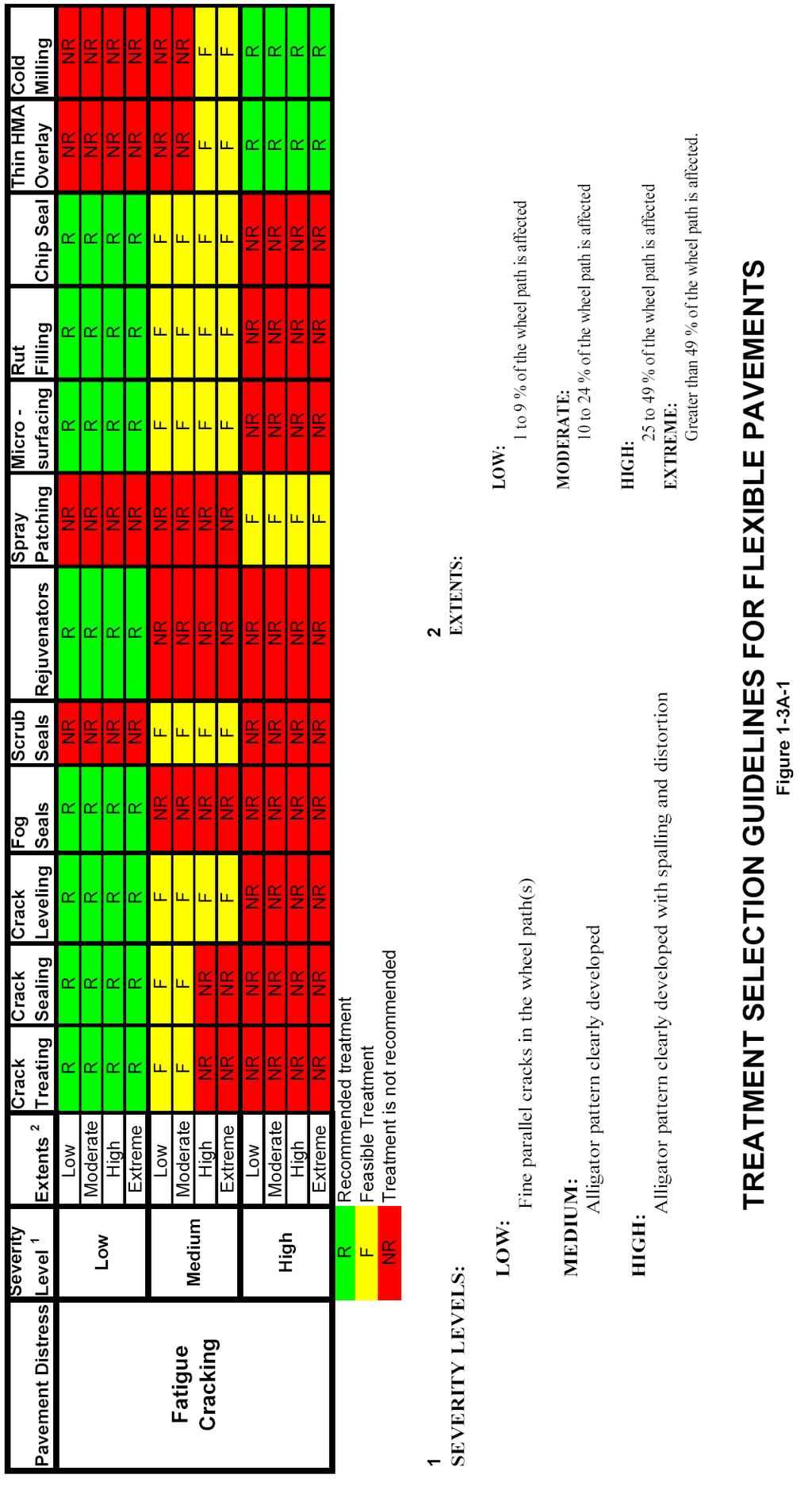
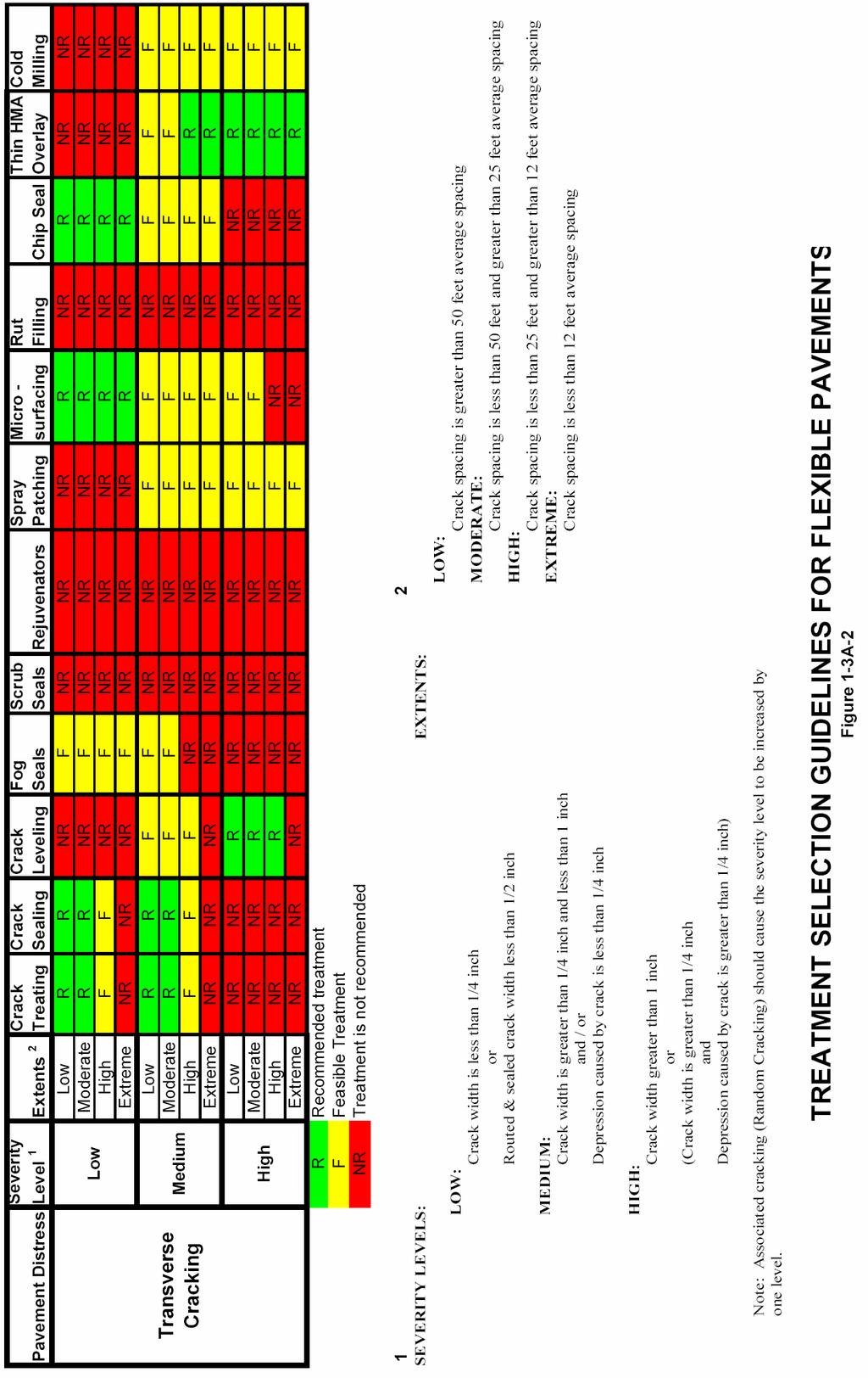
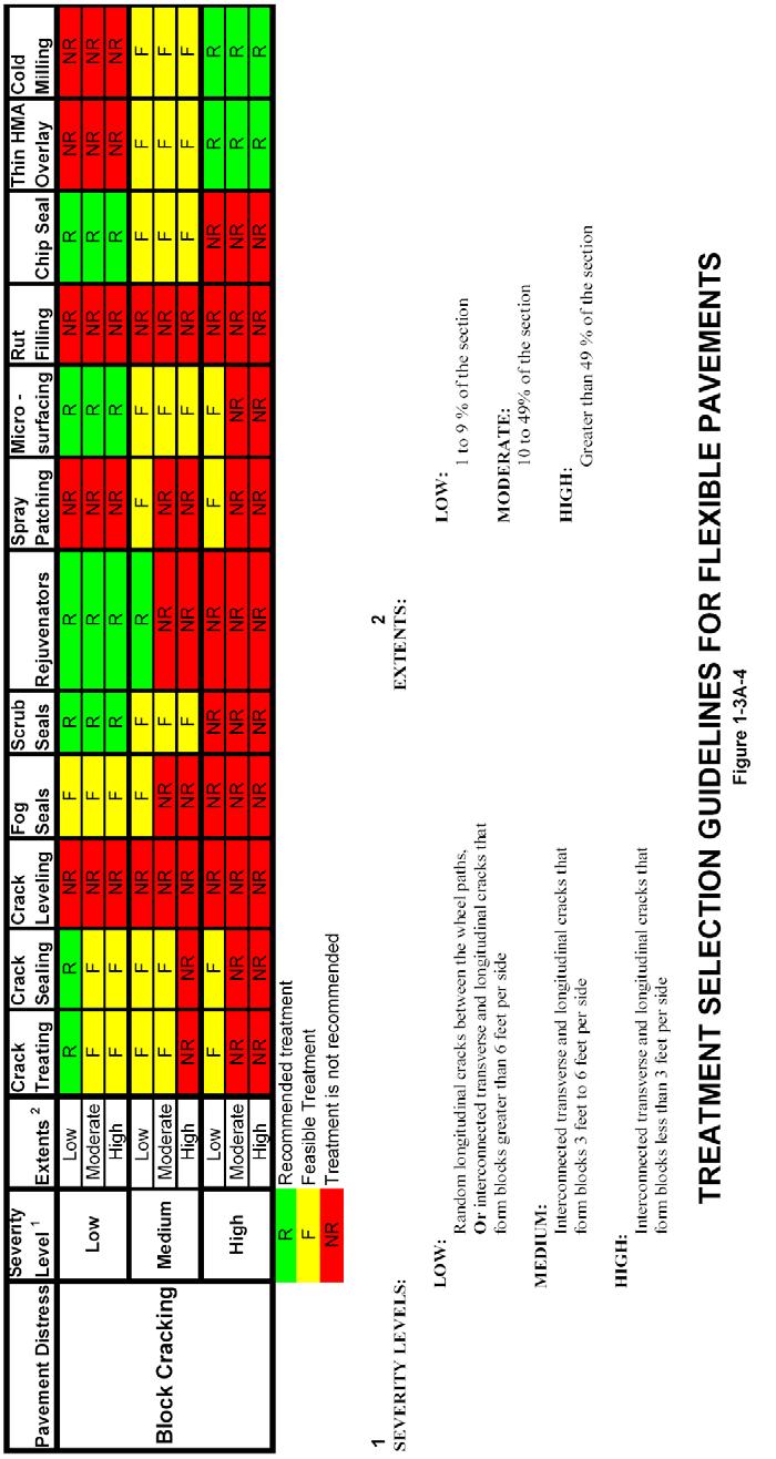
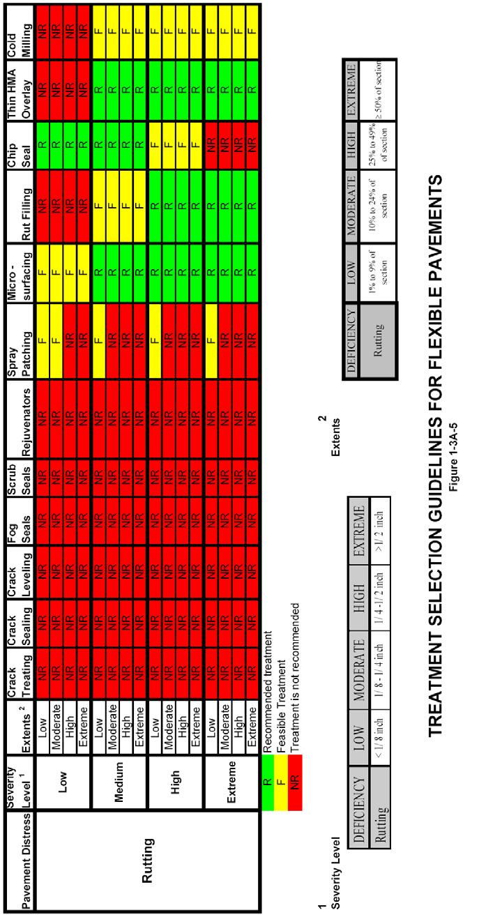
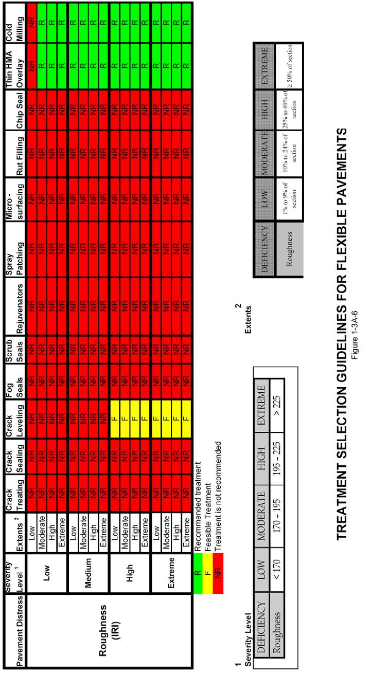
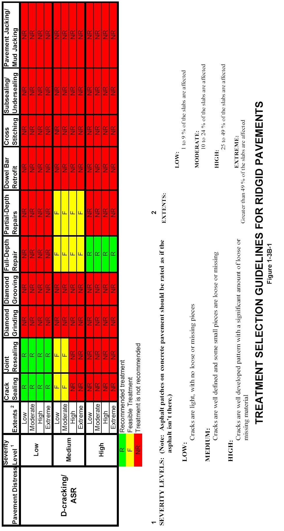
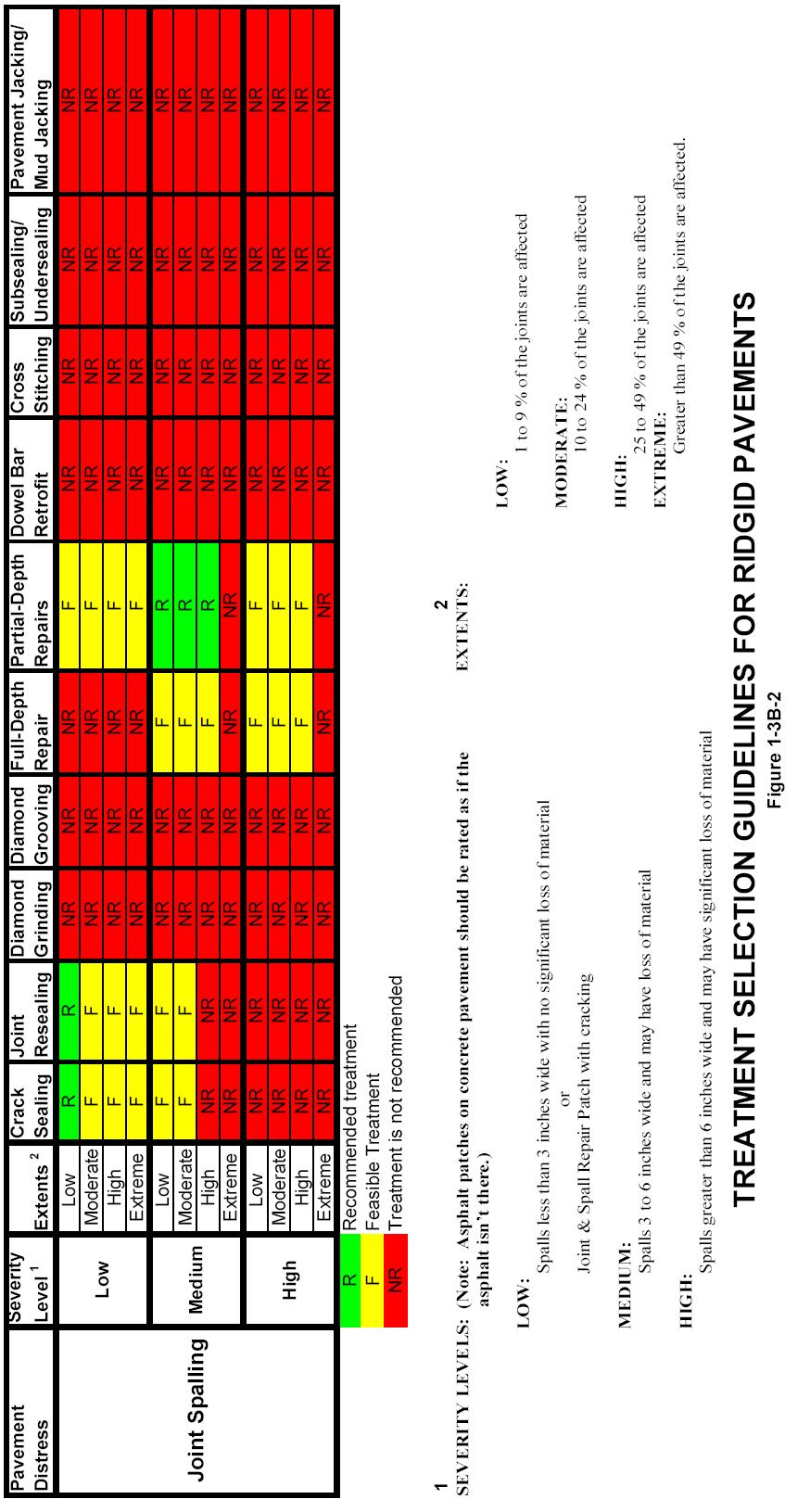
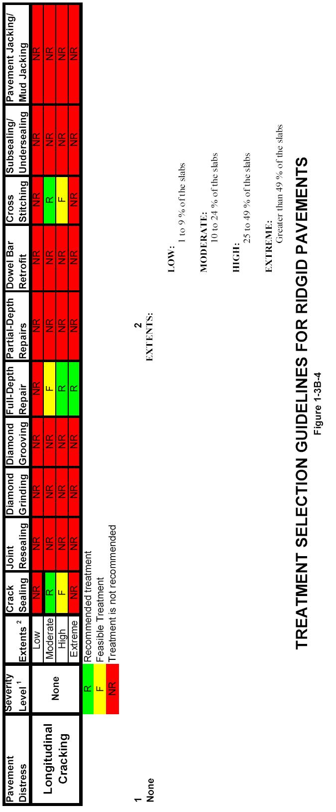
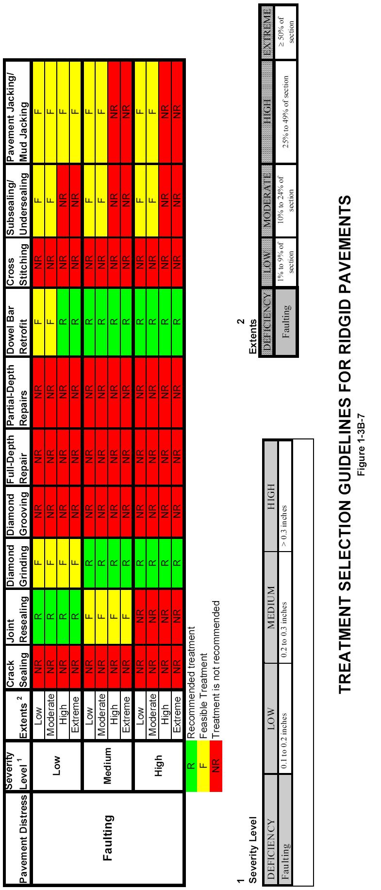
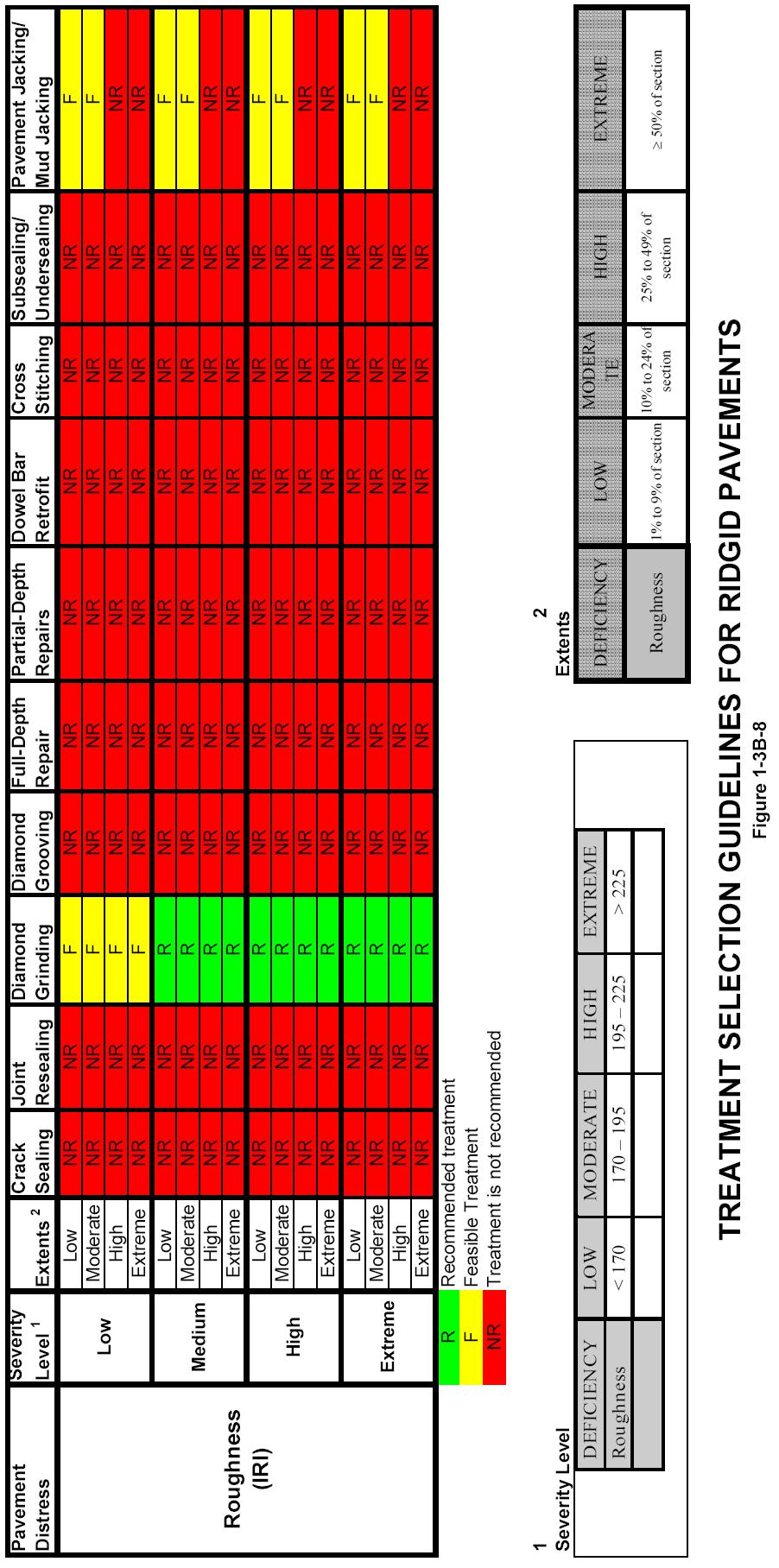
9 Assess Pavement Condition In addition to gathering historical pavement information, the current condition of the pavement must be assessed in order to determine feasible preservation treatments. Ideally the condition would be determined in the form of a standard condition rating procedure to include details of the types, severities, and the amounts of all distresses present on the pavement. The SDDOT S ENHANCED PAVEMENT MANAGEMENT System Synopsis document provides detailed information on the SDDOT s pavement management system Evaluate Pavement Data In order to determine whether a pavement section is a good candidate for pavement preservation treatments, the agency should consider the following: Is there excessive distress (large quantities and/or severe levels of distress) on the pavement section or are the occurring distresses a warning sign of an underlying structural problem? Is there evidence of structural problems Has the time for applying a pavement preservation treatment to the pavement while it is in good condition passed? Are there other known pavement problems (e.g., material problems or signs of construction problems) on the pavement section? Is there a history of pavement problems in this location? If the answer to the majority of these questions is no, then the pavement section is likely to be a good candidate for pavement preservation techniques. For pavement sections for which the answer to most of these questions is yes, the agency should not consider preservation techniques and instead plan major rehabilitation or future reconstruction for the roadway Identify Feasible Preservation Treatments The appropriate treatment strategy for those pavement sections identified as candidates for pavement preservation can be determined by looking at the type and severity of pavement distresses present on the pavement. Guidelines for determining recommended and feasible treatments are provided in figures 1-3A and 1-3B for flexible and rigid pavements. Figures 1-3A and 1-3B provide guidance for treatment selection based upon attributes such as distress levels, ride, friction, traffic levels, and relative cost. These characteristics are primarily based on a relationship between a single treatment and a single distress. When multiple distresses exist, the appropriate treatment to address each distress type should be examined and the recommended treatments must be used in combination with engineering judgment to make final treatment decisions.
10 Select Most Appropriate Preservation Treatment Of the feasible preservation treatments, the most appropriate treatment is one that can provide the best cost/benefit while meeting the constraints of the project. There are several methods to identify the treatment with the most benefit for the associated cost. This analysis is done internally within many pavement management systems. Ideally, the selection of the right treatment at the right time is governed by optimization (maximizing benefits for given constraints). However, treatment selection can be accomplished through a manual assessment of the benefits versus the projected project cost. In addition to the benefits and costs of the feasible treatments, the selection of the most appropriate preservation treatment also includes considering the variety of project constraints that affect treatment selection. The types of project constraints that should be considered when selecting the most appropriate preservation treatment include: Availability of qualified contractors. Availability of quality materials. Agency practice or local preference. Time (of year) of construction. Initial costs. User preferences. Pavement noise. Facility downtime. Surface friction. The effect of these constraints will vary from project to project and should be taken into consideration as the final projects are selected for inclusion in a pavement preservation program Identify Existing Pavement Distresses The Department performs continuous visual surveys on all state highways and interstate routes. This survey identifies and documents the type, extent and severity of a variety of pavement distresses. It is critical that when selecting a treatment type it is capable of correcting the existing pavement distress. The SDDOT s ENHANCED PAVEMENT MANAGEMENT SYSTEM Visual Distress Manual details the distresses monitored and provides definitions of the various distress types for both flexible and rigid pavements.
11 8
12 9
13 10
14 11
15 12
16 13
17 14
18 15
19 16
20 17
21 18
22 19
23 20
24 21
25 22 Surface Treatment Frequency Surfacing Age 1 st Year 2 nd Year 3 rd Year Years >20 Years Surfacing Type Mainline overlay w/initial sand seal Mainline overlay w/o initial sand seal Material Office Approval Needed Asphalt shoulder adjacent to AC w/ initial sand seal Asphalt shoulder adjacent to AC w/o initial sand seal Asphalt shoulder adjacent to PCCP 100% Asphalt Milling Shoulders Granular Shoulders Adjacent to Asphalt or Concrete Inspect for cracks and seal Inspect for cracks and seal - Visual Insp. For AST Inspect for cracks and seal Inspect for cracks and seal Inspect for cracks and seal particularly longitudinal joint Visually Inspect, may require addt l flush seal Visually Inspect, may require addt l gravel and blading AST with Fog Seal AST with mainline AST when mainline is done Visually Inspect, may require addt l gravel/ blading AST with Fog Seal AST w/ mainline AST between 3-5 years Visually Inspect, may require addt l gravel/ blading Visually inspect for cracks and seal as cracks appear. AST w/ Fog Seal on 6-8+ yr. frequency as determined by visual inspections Visually inspect for cracks and seal as cracks appear. AST w/ Fog Seal on 6-8+ yr. frequency as determined by visual inspections Visually inspect condition of shoulders. Seal as cracks appear. Flush seal with subsequent mainline AST Visually inspect condition of shoulders. Seal as cracks appear. Flush seal with subsequent mainline AST Visually inspect condition of shoulders. Seal as cracks appear. Flush seal on 8-10 yr. frequency 2-3 edge along PCCP flushed more frequently Visually inspect condition of shoulders. Flush seal on a 5-8 yr. frequency. AST on subsequent treatments based on visual inspection Visually inspect condition of shoulders. Re-graveling on a 5-8 yr. frequency. Visually inspect condition and request recommendation for resurfacing from Pavement Design Engineer Visually inspect condition and request recommendation for resurfacing from Pavement Design Engineer Visually inspect condition and request recommendation for resurfacing from Pavement Design Engineer Visually inspect condition and request recommendation for resurfacing from Pavement Design Engineer Visually inspect condition and request recommendation for resurfacing from Pavement Design Engineer Visually inspect condition and request recommendation for resurfacing from Pavement Design Engineer Visually inspect condition and request recommendation for resurfacing from Pavement Design Engineer Note: Surfacing placed on new grade or processed in place projects may not require an initial crack seal. FIGURE 1-3C
26 TREATMENTS Many different pavement preservation techniques and treatments are available. These range from localized applications to treatments that are applied to the entire pavement surface. For all preservation treatments, the purpose is to minimize the effects of pavement distress or prevent them from occurring. Commonly used preventive maintenance treatments and minor rehabilitation techniques are described in one-page summaries in this section. Further details regarding the treatments are available in the standard and supplemental specifications and the special provisions. Each treatment summary is followed by a simple pictorial representation of the major steps of the construction sequence for the treatment. The flexible and rigid pavement treatments that are presented are summarized in Figure 1-4A. Prior to the presentation of each treatment type is a Special Considerations section that provides details that are applicable to a variety of treatments. Treatments for Flexible Pavements Crack Treating Crack Leveling Rout and Seal Cracks Fog Seals Sand Seals Scrub Seals Rejuvenators Slurry Seals Microsurfacing Chip Seals Thin Asphalt Concrete Overlay Less than 1.5 Rut Filling Spray Patching Treatments for Rigid Pavements Crack Sealing Joint Resealing Diamond Grinding Diamond Grooving Full-Depth Repairs Partial-Depth Repairs Dowel Bar Retrofit (DBR) Cross Stitching Pavement Sub- sealing/ Under sealing Pavement Jacking / Mud Jacking Drainage Preservation TREATMENTS FOR FLEXIBLE AND RIGID PAVEMENTS Figure 1-4A
27 Special Considerations There are several special considerations that must be addressed prior to the construction of various pavement preservation techniques (a) Pavement Preparation Spot patching, rut filling, spray patching, FWD etc. Transportation Inventory Management has smoothness and rutting number s available for field use. All flexible pavement sections should be evaluated for the presence of bumps greater than ½ using a 10-foot straightedge or Transportation Inventory Management (TIM) will provide pavement rutting and longitudinal profile data in mile and tenth of a mile averages when requested. Bumps should be evaluated and ground prior to placing of the flexible treatment options that do not include milling or recycling of the pavement surface. Special attention should be given to properly cleaning all milled materials from the pavement surface prior to applying a treatment. A properly cleaned surface is imperative in order to obtain proper bonding to the underlying pavement for all flexible surface treatments. When crack sealing is needed prior to a preventive maintenance treatment, the treatment should be placed at least 3 months in advance to minimize difficulties and conflicts between treatment types and/or contractors (b) Pavement Markings A minimum of seven days of good drying weather is needed prior to the placement of paint striping on various flexible pavement treatments. Temporary striping of waterbased paint or foil-backed tape will be until permanent markings can be applied (c) Traffic Control Proper traffic control is needed to ensure acceptable cure times for the majority of treatments. Without proper traffic control after placement, premature failure of the preservation treatment may occur. For rigid pavements, the use of conventional patch materials is usually best for the long-term performance of the pavement but requires adequate curing which may not be available in high traffic volume areas or at certain times of the year (d) Treatment Sequencing When planning preservation work on rigid pavements, consideration should be given to the proper sequencing of treatments. For rigid pavements, an appropriate treatment sequence consists of the following: full- or partial-depth repairs, load transfer restoration, diamond grinding, and joint resealing.
28 (d) Treatment Sequencing Where epoxy or plastic pavement marking exists, coordination of the selected treatment should coordinate to maximize the life of the pavement marking (e) Rumble Strips/Stripes During the design process refer to Chapter 7 of the SDDOT Road Design Manual and include the installation of rumble strips or rumble stripes with the project as per the guidance provided.
29 Flexible Pavement Treatment Summaries (a) Crack Treating Performance Standard 2110 Crack treating is effective at reducing or delaying moisture damage, further crack deterioration, roughness, and rutting. However, crack treating can also have a negative impact on roughness and friction. (See Figure 1-4B) Treatment Description: Crack treating is the process of placing material into working/non-working cracks to substantially reduce infiltration of water and to reinforce the adjacent pavement. Crack treating is characterized by minimal crack preparation and the use of lower quality bituminous filler materials. Pavement Conditions Addressed: Adds no structural benefit, but does reduce moisture infiltration through cracks. Only practical if extent of cracking is minimal and if there is little to no structural cracking. Application Limitations: These treatments are not recommended when structural failures exist (i.e., extensive fatigue cracking or high severity rutting) or if there is extensive pavement deterioration, or little remaining life. Crack treating is appropriate for cracks up to 1 inch wide. Backer rod may be used in large cracks to minimize the sealant material usage, if backer rod is used a minimum depth of 1 of sealant should be provided. Construction Considerations: Placement should occur during cool, dry weather conditions. Application during cool weather will allow for expanded crack widths. Proper crack cleaning and a dry crack are essential to achieve good bond and maximum performance. During the placement care should be taken when moisture is present in the pavement layers to insure that proper bonding of the sealant occurs. Traffic Considerations: Performance is not significantly affected by varying ADT or truck levels. However, improper installation can permit the filler to fail. Special Considerations: Crack treating may have negative effects. Undesirable visual impacts may occur, which include tracking of filling material by tire action, obscuring lane markings, and adversely affecting friction/skid resistance. Crack treating may result in a rougher pavement surface when the filler material is forced out of the cracks during warm months. Performance Period: 2 to 4 years. Relative Cost ($ to $$$$): $


30 27 Step 1. Crack cleaning. The crack treating process requires minimal crack preparation. This typically consists of using compressed air to clean the cracks. Step 2. Application of crack filler. This photo shows the application of a crack filler using an overbanded configuration. A squeegee should be used to provide a 1 to 3 overband on each side of the crack. Step 3. Application of blotter. For hot-applied materials, a blotter coat of sand is often used to reduce tracking of the material by vehicle tires. A more typical procedure is to use a single ply of toilet tissue to prevent tracking. GENERAL CRACK FILLING STEPS FIGURE 1-4B
31 (b) Rout and Seal Cracks Performance Standard 2110 Routing and sealing of cracks is effective at reducing or delaying moisture damage, further crack deterioration, roughness, and rutting. However, crack sealing can also have a negative impact on roughness and friction. (See Figure 1-4C) Treatment Description: Routing and sealing of cracks is the process of placing higherquality material into working cracks (i.e., those that open and close with changes in temperature) in order to reduce water infiltration into a pavement. In contrast to crack treating, routing and sealing of cracks requires more substantial crack preparation procedures and uses higher quality sealant materials. Thermosetting and thermoplastic materials are both used for crack sealing. Pavement Conditions Addressed: Does not add structural benefit, but does reduce future intrusion of incompressible materials, water and soluble chemicals (e.g., salts and brines) into the cracks. It is only practical if extent of cracking is minimal and if there is little to no structural cracking. Application Limitations: These treatments are not recommended when structural failures exist (i.e., extensive fatigue cracking or high severity rutting) or if there is extensive pavement deterioration, or little remaining life. Routing and sealing of cracks is appropriate for cracks up to 1 wide. Construction Considerations: Placement should occur during cool, dry weather conditions with moderate yearly temperatures. Proper crack preparation and cleaning is essential to good bond and maximum performance. Some agencies also use a hot compressed air lance prior to sealing. Cracks that are routed should be routed to a width of 5/8 and a depth of 5/8. Cracks with a depth greater than 5/8 should have a backer rod inserted to a depth to provide a sealant depth equal to the sealant width. During the placement care should be taken when moisture is present in the pavement layers to insure that proper bonding of the sealant occurs. Traffic Considerations: Performance is not significantly affected by varying ADT or truck levels. However, improper installation can permit the sealant to fail (b) Rout and Seal Cracks Performance Standard 2110 Special Considerations: Routing and sealing of cracks may have negative effects. Undesirable visual impacts may occur, which include tracking of sealing material by tire action, obscuring lane markings, and adversely affecting skid resistance. Routing and sealing of cracks may result in a rougher pavement surface when the sealant material is forced out of the cracks during warm months. Sealing is best accomplished several months in advance of any other preventive maintenance surface applications. Performance Period: 2 to 8 years. Relative Cost ($ to $$$$): $


32 29 Step 1. Crack Routing. A uniform sealant reservoir increases the probability of a neater, better performing sealant installation. Step 2. Cleaning and drying. Cracks must be clean and dry to facilitate sealant bonding. Step 3. Material application. This photo shows the application of sealant using a simple band-aid configuration. A squeegee should be used to provide a 1 to 3 overband on each side of the crack. Step 4. Application of blotter. For hot applied materials, a blotter coat of sand is often used to reduce tracking of the material by vehicle tires. A more typical procedure is to use a single ply of toilet tissue to prevent tracking. GENERAL CRACK SEALING STEPS Figure 1-4C
33 (c) Fog Seals or Flush Seals Performance Standard 2108 Fog seals are effective at sealing the pavement, inhibiting raveling, enriching the hardened/oxidized asphalt, and providing some pavement edge-shoulder delineation. However, fog seals can have a negative impact on friction and stripping in susceptible HMA pavements. (See Figure 1-4D) Treatment Description: Fog seals are very light applications of a diluted asphalt emulsion placed directly on the pavement surface with no aggregate. Typical application rates range from 0.05 to 0.10 gal per yd 2. This treatment is commonly used on mainline and shoulders. Pavement Conditions Addressed: Does not add structural capacity. Fog seals are placed primarily to seal the pavement, inhibit raveling, slightly enrich a hardened/oxidized asphalt, and provide some pavement edge-shoulder delineation. No structural benefit is added by this treatment. Prior to treatment placement it maybe necessary to perform other treatments to address other issues, such as rut filling, patching, crack treating or sealing, or spray patching. Vegetation control on the shoulder treatments should be considered and applied as per Performance Standard 2305 either prior to the treatment or as part of the treatment. Application Limitations: This treatment is not recommended when structural failures exist (e.g., significant fatigue cracking) or if there is already flushing/bleeding, friction loss, or thermal cracking. Construction Considerations: Typically, a slow-setting emulsion (e.g., CSS-1H, SS- 1H) is used, which requires time to break. Because of this, the pavement is sometimes closed for 2 hours for curing before being re-opened to traffic. Traffic Considerations: Increased ADT or truck levels can increase surface wear. Special Considerations: Special consideration should be given to the pavement markings and bump grinding prior to treatment placement. Prior to treatment application care should be taken to prevent over spraying onto the existing pavement marking by using the proper shield on the spray bar or if necessary the pavement marking tape should be masked. Performance Period: 1 to 3 years. Relative Cost ($ to $$$$): $

.")
34 31 Step 1. Surface preparation. The surface must be free of dust, dirt, and debris prior to applying the emulsion. Step 2. Application of emulsion. The emulsion is applied using a distributor truck. Step 3. Sand blotter and sweeping (if necessary). Sand blotters can help address a problem with delayed curing, as well as early opening to traffic. Sweeping may be required to remove excess sand. GENERAL FOG SEAL CONSTRUCTION STEPS Figure 1-4D
35 (d) Scrub Seals Scrub seals are effective at filling narrow cracks ½ wide, rejuvenating hardened/oxidized asphalt, and improving poor friction. (See Figure 1-4E) Treatment Description: A scrub seal is a thin asphalt surface treatment constructed by spraying a polymer modified rejuvenating emulsion onto an existing pavement, dragging a broom across the surface to scrub the emulsified asphalt into the surface cracks, immediately spreading a thin layer of fine aggregate (i.e. sand or screenings) over the emulsified asphalt, dragging another broom over the surface to scrub the fine aggregate into the surface cracks, and rolling the surface with a pneumatic tire roller. Thicknesses generally range from ¼ to 3/8. Pavement Conditions Addressed: Does not add structural capacity. Scrub seals are primarily placed to fill narrow cracks, rejuvenate oxidized asphalt, and improve poor friction. No structural benefit is added by this treatment. Prior to treatment placement it maybe necessary to perform other treatments to address other issues, such as rut filling, patching, crack treating or sealing, or spray patching. Application Limitations: This treatment is not recommended when structural failures exist (e.g., fatigue cracking) or if there is extensive pavement deterioration, or little remaining life. Scrub seals should not be applied to pavements with ruts greater than ¼ deep, unless a rut filling treatment is placed prior to the scrub seal. Construction Considerations: Scrub seals should be constructed when conditions are dry (i.e., the risk of rain is not likely which would hinder the proper construction of the scrub seal) and when the minimum air temperature is moderate (i.e., normally 50 F [10 C] or above). To assure good bond to the existing pavement, the surface should be clean and dry prior to emulsion placement. Traffic Considerations: Scrub seals should generally be limited to lower volume traffic conditions with a low percentage of trucks. Special Considerations: Special consideration should be given to the pavement markings and bump grinding prior to treatment placement. Scrub seals are susceptible to snow plow damage. Pavement marking tape should be masked prior to placing treatment. Performance Period: 5 to 7 years. Relative Cost ($ to $$$$): $$


36 33 Step 1. Surface preparation. The surface must be free of dust, dirt, and debris prior to applying the emulsion. Step 2. Emulsion application and dragbrooming. Drag-brooming is used to work emulsion into cracks and surface voids. Step 3. Sand application. A thin layer of sand is applied to the broomed emulsion. Steps 4 & 5. Drag-brooming of sand and rolling. After the application of sand, the surface is drag-broomed again and rolled with pneumatic-tired rollers. GENERAL SCRUB SEAL CONSTRUCTION STEPS Figure 1-4E
37 (e) Rejuvenators Rejuvenators are effective at restoring the original properties to aged asphalt binder thus reducing the effects of raveling or roughness,. (See Figure 1-4F) Treatment Description: Rejuvenators are specialized emulsions that are sprayed on an existing asphalt surface with the intent of softening the existing binder, enriching the weathered pavement, and thereby, inhibiting raveling. The emulsions used as rejuvenators are typically mixtures of asphalt, polymer latex, and other additives. Rejuvenating emulsions can be used in a fog seal, sand seal, scrub seal, or any other surface seal applied directly to the pavement surface. Pavement Conditions Addressed: While rejuvenators do not directly correct any distresses, they are effective at softening the existing binder; thereby, slowing the development of raveling, thermal cracking, and roughness. Prior to treatment placement it maybe necessary to perform other treatments to address other issues, such as rut filling, patching, crack treating, crack sealing, or spray patching. Application Limitations: This treatment is not recommended when structural failures exist (e.g., fatigue cracking), where the surface has poor friction, or if there is extensive pavement deterioration or little remaining life. Construction Considerations: Choosing an appropriate rejuvenating agent, and determining the correct application rate for the existing pavement s material characteristics and condition, are the most important construction-related considerations. Field testing needs to be conducted to determine the correct application rate. Traffic Considerations: Rejuvenators are effective on asphalt surfaces in all traffic conditions. However, traffic should not be allowed back on the surface until adequate friction is restored. This is often provided by the placement of manufactured sand prior to opening to traffic. Special Considerations: When selecting a rejuvenator for a project, questions regarding available materials can be directed to the SDDOT Materials Office. Performance Period: 3 to 5 years. Relative Cost ($ to $$$$): $$


38 35 Step 1. Rejuvenator application. The rejuvenating emulsion is applied to the surface using a distributor truck. Step 2. Light sanding. After the rejuvenator has been allowed to be absorbed for the recommended amount of time, a light application of sand is often applied to improve skid resistance. GENERAL REJUVENATOR CONSTRUCTION STEPS Figure 1-4F
39 (f) Micro-surfacing Micro-surfacing is effective at correcting or inhibiting raveling and oxidation of the pavement surface, improving surface friction, sealing the pavement surface, and filling minor surface irregularities and wheel ruts up to 1 ¼ deep. (See Figure 1-4G) Treatment Description: Micro-surfacing consists of a mixture of latex-modified emulsified asphalt, mineral aggregate, mineral filler, water, and additives. Microsurfacing material is mixed in specialized, compartmented, self-powered trucks and placed on the pavement using an augered screed box. Pavement Conditions Addressed: Does not add structural capacity but will provide protection of surface distresses like low-severity cracking; raveling/weathering (loose material must be removed); low- to medium-severity bleeding; minor roughness; friction loss; and moisture infiltration. Micro-surfacing will also temporarily seal fatigue cracks (if severity is low) and can serve as a rut-filler (if the existing ruts are stable). A scratch coat of the microsurfacing can be used for light profile repairs. Prior to treatment placement it maybe necessary to perform other treatments to address other issues, such as rut filling, patching, crack treating, crack sealing, or spray patching. Application Limitations: Micro-surfacing is not recommended when the pavement contains structural failures (e.g., significant fatigue cracking), high-severity thermal cracking, or extensive pavement deterioration. This treatment can also accelerate the development of stripping in susceptible AC pavements. Construction Considerations: Avoid placement in hot weather if there is potential for flushing problems. Placement in cool weather can lead to early raveling. Do not place when freezing temperatures are expected. The micro-surfacing material shall be spread only when the surface temperature on a shaded portion of the existing surface is above 50 F (10 C) and rising and when the weather is not foggy or rainy. No Micro-surfacing shall be placed when there is a danger that the finishing product will freeze within 24 hours. Micro-surfacing material shall not be placed before June 1 or after September 15. A 300 foot (100 m) minimum test section to determine surface characteristics and set time must be constructed and approved by the Engineer prior to commencing paving operations. A portion of the test section shall be at least ¾ inch (19mm) thick. Avoid premature placement of pavement markers and striping. A minimum of 7 days of good drying weather should be allowed before placement of new markers or striping with temporary markers used prior to permanent placement. Micro-surfacing typically breaks within a few minutes of placement and can carry traffic after approximately an hour.
40 (f) Micro-surfacing Traffic Considerations: Very successful on both low and high volume roadways. However, areas of heavy truck turning or down grade locations are best avoided as there is a high potential for early damage. The dusting of a blotter material can be used to allow for earlier opening of intersections and turning lanes. Special Considerations: The designer should use the SDDOT Special Provision for Polymer-Modified Micro-surfacing as a basis for use of this treatment. If micro-surfacing is being used to fill ruts, this must be specified on the plans along with appropriate gradation and application rate. Special consideration should be given to the raised pavement markers and bump grinding prior to treatment placement. Performance Period: 4 to 7 years. Relative Cost ($ to $$$$): $$


 need to be protected prior to paving. Step 3.")

41 38 Step 1. Repair existing distress. Any structural failures should be patched, and non-working cracks >1/4 wide should be sealed. Step 2. Prepare surface. Surface must be clean, and striping must be removed. All other in-pavement fixtures (e.g., manholes) need to be protected prior to paving. Step 3. Microsurfacing placement. This photo shows the placement of material using a microsurfacing spreader box. Step 4. Hand work. Some handwork may be required to smooth edges. Excessive handwork can segregate the mix as well as leave an unsatisfactory finish. GENERAL MICRO-SURFACING CONSTRUCTION STEPS Figure 1-4G
42 (g) Asphalt Surface Treatments (AST) AST, also known as chip seals or sand seals, are effective at improving poor friction, inhibiting raveling, correcting minor roughness and bleeding, and sealing the pavement surface. (See Figure 1-4H) Treatment Description: Asphalt (commonly an emulsion) is applied directly to the pavement surface (0.26 to 0.46 gal/yd 2 ) followed by the application of aggregate chips (16 to 30 lb/yd 2 ), which are then immediately rolled to imbed chips (50 to 70 percent). Application rates depend upon aggregate gradation and maximum size. This treatment can be applied in multiple layers (e.g., double chip seals) and in combination with other surface treatments. Pavement Conditions Addressed: Does not add structural capacity but will provide benefits to pavement distresses like longitudinal, transverse, and block cracking; raveling/weathering (loose material must be removed); friction loss; minor roughness; low-severity bleeding; and moisture infiltration. The flexible impermeable AC surface helps reduce cracking and is somewhat effective at sealing medium-severity fatigue cracks in comparison with other treatments. Prior to treatment placement it maybe necessary to perform other treatments to address other issues, such as rut filling, patching, crack treating, crack sealing, or spray patching. Application Limitations: Not recommended for pavements with the following conditions: structural deficiency; cracks >1/4 wide; medium- to high-severity alligator cracking; many potholes; rutting > 1 deep; very rough surface. AST can also accelerate the development of stripping in susceptible AC pavements. Construction Considerations: Surface must be clean. Treatment should be placed during warm weather with chip spreader immediately behind asphalt distributor and rollers close behind the spreader. AST are placed from May 15 to September 1 and when the temperature in the shade is above 70 F. Placement after September 1 st is discouraged. Approximately 2 hours of cure time are required before roadway may be re-opened to normal speed traffic. Brooming is usually required to remove loose chips. Pilot vehicles should be used to make sure traffic does not damage the fresh surface and to reduce windshield breakage and other vehicle damage. Lightweight aggregate can be used to help minimize claims. Flaggers may be needed at crossing intersections to control traffic. Avoid premature placement of pavement markers and striping. A fog seal is recommended on all application to prevent aggregate loss and potential vehicle damage. Fog seal should be placed on mainline AST only. If shoulders do not receive AST the fog seal should be placed on the shoulders full width. Prior to fog seal the surface should be clean of excess chips.
43 (g) Asphalt Surface Treatments (AST) Initial AST should be done full width to include the shoulder. Subsequent AST should be done 23 wide on mainline. This will allow pavement marking paint to be recessed and extend the life of the pavement marking. Asphalt shoulders should be fog sealed when the subsequent mainline AST is applied. When rumble strips are present only one AST should be applied. A second application can fill the rumble and reduce the effectiveness. During second or third application the rumble should be fog sealed when the mainline is fog sealed or in a separate application. Or if AST is applied to rumble strip it will need to be re-ground. Traffic Considerations: With special design and proper placement, AST can perform well on high-volume roads. Traffic should be notified by flaggers while the work is being preformed and of the potential for vehicle damage on the project. Special Considerations: The designer should use the Modified McLeod Design Procedure as a basis for use of the treatment and incorporate standard plan notes. Special consideration should be given to the bump grinding prior to treatment placement. The Minnesota Seal Coat Handbook provides a good reference on AST including proper design and construction procedures. Performance Period: Single seals: 6 to 8 years. Relative Cost ($ to $$$$): $$


44 41 Step 1. Surface preparation. Surface must be clean and dry to ensure good bond with the asphalt. Step 2. Binder application. The asphalt binder is applied to the surface with a distributor truck. Step 3. Aggregate application. A selfpropelled, pneumatic-tired, motorized unit has a hopper on the front where the chips are dumped. Steps 4 & 5. Rolling and brooming. After the application of the aggregate, the surface is rolled with pneumatic-tired rollers and broomed to remove excess aggregate. GENERAL AST CONSTRUCTION STEPS Figure 1-4H
45 (h) Thin HMA Overlay (Less than 1.5) The application of a thin HMA overlay is a viable option for improving ride ability and surface friction, reducing hydroplaning and tire splash (using an open graded friction course), and improving the profile, crown, and cross slope. (See Figure 1-4I) Treatment Description: Plant-mixed combinations of asphalt cement and aggregate applied to the pavement in thicknesses between about ¾ and 1 ½. Dense-graded, open-graded, and stone matrix mixes are all used. Thin HMA overlays consists of placing a 1 ½ single-pass overlay on a previously resurfaced pavement that is not in need of significant repair and is in good condition. If the overlay is applied at the correct time, it can delay serious distresses, extend the life of the pavement, and decrease the overall cost. Pavement Conditions Addressed: Structural capacity of the pavement is increased and will provide benefits to pavement distresses like low-severity cracking; raveling/weathering (loose material must be removed); friction loss; roughness; lowseverity bleeding; low-severity block cracking (may perform better with additional milling). Thin overlays may also be used to correct rutting but will require the use of a separate rut-fill application. Application Limitations: Thin HMA overlays are not recommended where there are serious structural failures (e.g., fatigue cracking), extensive pavement deterioration, or if there is high-severity thermal cracking. Surface should be uniform to ensure uniform compaction. Construction Considerations: Surface must be clean. A tack coat is required prior to overlay placement and will help improve the bond to the existing surface. Thin HMA overlays dissipate heat rapidly and, therefore, depend upon minimum specified mix placement temperatures and timely compaction. A blade laid leveling course should be considered prior to the overlay depending on the existing pavement condition. Traffic Considerations: Performance is not affected by different ADT or percent trucks. Thin AC overlays are not structural layers and as such should not be subjected to strain from loadings. Such layers may be subject to top-down cracking under certain combinations of loadings, environmental conditions, and pavement structures. Special Considerations: Localized distressed areas should be repaired prior to the placement of the overlay. If milling is not used in conjunction with the thin HMA overlay, special consideration should be given to bump grinding prior to treatment placement. Performance Period: 10 to 15 years depending upon thickness. Relative Cost ($ to $$$$): $$$


46 43 Step 1. Pre-overlay repair & surface preparation. Localized areas of distress are repaired prior to overlay placement and milling may be used. Step 2. Tack coat. A tack coat is used to promote bonding between the overlay and the existing pavement. Step 3. AC Overlay. Material is placed with conventional equipment. Step 4. Compaction. Steel-wheeled rollers are used to compact the overlay. GENERAL THIN HMA OVERLAY CONSTRUCTION STEPS Figure 1-4I
47 (i) Cold Milling Cold milling is effective at removing distresses in the top of the pavement, providing a smoother surface by removing vertical deformations, and improving surface friction. (See Figure 1-4J) Treatment Description: Cold milling involves the removal of part or all of an existing asphalt concrete surface. This treatment is frequently used to prepare an asphalt surface for an asphalt concrete overlay and is not generally suggested as a stand alone treatment. It also can be utilized to improve smoothness prior to applying other applications or correct bumps or dips, at box culverts, structure approaches or other locations. Pavement Conditions Addressed: Adds no structural benefit, but removes surface cracking and roughness, and restores friction. It can also be used to restore proper grades and cross-slopes on existing pavement. Application Limitations: This treatment is not recommended for structurally deficient pavements unless the asphalt overlay is designed to add structural capacity. Construction Considerations: The following are keys to obtaining a quality milled surface: Use a good working milling machine with a 12-ft (3.7-m) recommended width Control milling speed to achieve a smooth uniform surface (30 ft/min [9.14 m/min] or slower for deep cuts) Use a 28-ft ski to control grade and a string line for longitudinal guidance Perform pavement patching prior to milling Remove manhole castings and cover holes prior to milling Adjust manhole casting after milling to meet final surface elevation If this treatment is a used as a stand alone treatment, a fine-toothed milling drum is needed to improve the smoothness and safety of the milled surface Traffic Considerations: Cold milling can be used with all traffic levels. Special Considerations: While not generally suggested as a stand alone treatment if the SDDOT Materials Office reviews and agrees upon the implementation plan, cold milling without applying another treatment to the milled surface may be considered. In order for the milled surface to be used as stand alone treatment, the pavement must be structurally sound with at least 3 of the existing asphalt concrete remaining in place and
48 (i) Cold Milling the removed material must be equal to an existing lift (at least 1 to 1 ½ of binder course remains). Also, the existing mixture must have a high fines content and low air voids content to avoid raveling. Performance Period: Remaining life of the pavement (doesn t extend life). Relative Cost ($ to $$$$): $


49 46 Step 1. Prepare surface. Patching should be completed before milling. All other inpavement fixtures (e.g., manholes) need to be protected prior to cold milling. Step 2. Milling. Milling is used to remove distresses such as segregation, rutting, raveling, or block cracking. COLD MILLING GENERAL CONSTRUCTION STEPS Figure 1-4J
50 (j) Crack Leveling Crack leveling is effective at providing a smoother ride across cracks that are depressed due to thermal cracking. (See Figure 1-4K) Treatment Description: Crack leveling involves placing a specialized mastic material heated in hot kettle mixer to level the cracks. Pavement Conditions Addressed: Does not add structural benefit, but does remove surface cracking and roughness. Application Limitations: This treatment is not recommended for structurally deficient pavements. Crack leveling should be considered when cracks is depressed a minimum of ¼. Construction Considerations: The application requires the use of specialized materials and equipment capable of placing the heated material. A squeegee is used to level the material transversally across the joint. An adequate sized squeegee should be used to assure the depression is completely filled to provide the best ride improvement. Multiple passes may be required after material has cooled to fill deeper cracks. Under sealing should be considered when excessive depression of the crack exists. Traffic Considerations: Crack leveling can be used at all traffic levels. Special Considerations: Crack leveling is an excellent treatment to be placed prior to subsequent treatments such as asphalt surface treatment or micro-surfacing. Crack leveling will typically be done on thicker asphalt pavements. Performance Period: 5-8 years Relative Cost ($ to $$$$): $$


51 48 Hot kettle equipped with chute facilitates placement across the joint prior to striking the material level with a squeegee. Finish product after leveling and prior. GENERAL CRACK LEVELING FIGURE 1-4K
52 (k) Rut Filling Rut filling is effective at filling ruts in the wheel paths and restoring proper cross slope on the roadway. Treatment Description: Rut filling involves placing a hot asphalt mix, typically a fine mix, with the use of a wedge box in the wheel path or rut location. Pavement Conditions Addressed: Rut filling will correct ruts in excess of ½ in depth and will provide minimal structural benefit, depending on the thickness placed. Application Limitations: This treatment is not recommended for structurally deficient pavements. Construction Considerations: Rut filling requires the use of a wedge box, typically 4 wide, mounted on a front end loader. If available a fine mixture of hot mix asphalt should be used, but care should be taken to insure that the material contains fractured aggregate to resist future rutting. Traffic Considerations: Rut filling can be used with all traffic levels. Special Considerations: Rut filling is an excellent treatment to place prior to subsequent treatments such as asphalt surface treatment or micro-surfacing. Transportation Inventory Management can provide rutting values in tenth of a mile increments to aid in determining potential routes needing rut filling. Performance Period: 4-6 years Relative Cost ($ to $$$$): $$
 Treatment Description: Spray patching involves using an asphalite machine to apply a mixture of aggregate and emulsified asphalt to fill a pothole, wide cracks, or other distressed")
53 (l) Spray Patching Spray patching is effective at filling potholes, wide cracks, and other localized distressed areas in an asphalt pavement. (See Figure 1-4L) Treatment Description: Spray patching involves using an asphalite machine to apply a mixture of aggregate and emulsified asphalt to fill a pothole, wide cracks, or other distressed areas in a pavement. The application is typically used when the patch thickness is minimal and the distressed area is smaller. Pavement Conditions Addressed: Spray patching will provide a filler in potholes, wide cracks, or other distressed areas in an asphalt pavement. Application Limitations: This treatment is not recommended for structurally deficient pavements. Construction Considerations: Spray patching requires an asphalite machine capable of applying the aggregate and emulsified asphalt such as CRS2. Traffic Considerations: Spray patching can be used with all traffic levels. Special Considerations: Spray patching treatment can be placed prior to subsequent treatments such as asphalt surface treatment or micro-surfacing. Performance Period: 2-6 years Relative Cost ($ to $$$$): $$ SPRAY PATCHING FIGURE 1-4L
54 Rigid Pavement Treatment Summaries (a) Crack Sealing Performance Standard 2129 Crack sealing is effective at reducing or delaying moisture damage, as well as crack deterioration and associated roughness. However, roughness can also be increased as a result of the sealing process itself, particularly if placed in an over band configuration. (See Figure 1-4M) Treatment Description: Crack sealing is an operation involving thorough crack preparation and placement of high-quality materials into or over candidate cracks to significantly reduce moisture infiltration and to retard the rate of crack deterioration. Sealed cracks in PCC pavements deteriorate less and contribute less to the overall deterioration of the pavement. PCC cracks are typically sealed with hot-poured sealant materials or silicone depending on the field conditions, the Concrete Engineer should be consulted prior to sealing cracks to insure the proper material is used. Pavement Conditions Addressed: Crack sealing is effective at sealing low- or medium-severity transverse or longitudinal cracks where the crack width is ½ to ¾. Joints that are wider than ¾. should be considered for other treatment. Full-depth working transverse cracks typically experience the same range of movement as transverse joints; therefore, it is recommended that these cracks be sealed to reduce water and incompressible infiltration. Application Limitations: Crack sealing is most effective when performed on PCC pavements that exhibit minimal structural deterioration and in which the cracks are not showing other significant distress such as faulting or spalling. Specific distresses such as corner cracking should be repaired with other treatment. Small or hair line cracks may not be a working crack in which case routing and sealing should not be done. Construction Considerations: Sealant performance is dependent on many construction factors, including material type and placement geometry, and application in a clean and dry substrate. Specialized saw used for routing concrete should be used to prepare the crack. Use of blotting material such as toilet paper should be used to prevent pulling by traffic. Traffic Considerations: Performance is not significantly affected by varying ADT or truck levels but should be allowed to cure before opening to traffic. However, improper installation can permit the sealant to fail.
55 (a) Crack Sealing Performance Standard 2129 Special Considerations: Crack sealing may have negative effects. Undesirable visual impacts may occur, which include tracking of sealing material by tire action, obscuring lane markings, and adversely affecting skid resistance. Crack sealing may result in a rougher pavement surface when the sealant material is forced out of the cracks during warm months. Performance Period: 4 to 8 years. Relative Cost ($ to $$$$): $


56 53 Step 1. Crack routing. Small crack saws are used to reface cracks and create a reservoir for the sealant. Step 2. Cleaning. Cracks must be clean and dry to enhance sealant bonding. Step 3. Application of sealant. The last step is to place the sealant in the refaced crack per governing specifications. CRACK SEALING Figure 1-4M
57 (b) Joint Resealing Performance Standard 2129 Joint resealing is effective at keeping moisture out of the pavement layers and incompressible materials out of joints, which reduces faulting, pumping, and spalling. (See Figure 1-4N) Treatment Description: Resealing transverse joints in PCC pavements is intended to minimize the infiltration of surface water into the underlying pavement structure and to prevent the intrusion of incompressible materials into the joint. A range of materials from bituminous to silicone are used in various configurations. Typical application is done 10 to 20 years after the initial silicone sealant was placed and 4 to 15 years for hot-poured asphalt sealant. Pavement Conditions Addressed: Joint resealing is effective at keeping moisture out of the pavement layers, and incompressible materials out of joints, which can result in less faulting, pumping, and spalling. Application Limitations: Joint resealing is most effective when performed on PCC pavements that exhibit minimal structural deterioration. Material selection should be based on the expected time until next treatment. Construction Considerations: Sealant performance is dependent on many construction factors, including material type and placement geometry, and application in a clean and dry substrate. Traffic Considerations: Performance is not affected by different ADT or percent trucks. Silicone sealants which are not properly recessed are more likely to fail in the wheel path. Special Considerations: Joint resealing is necessary when the existing sealant has deteriorated to the point that it readily allows water and incompressible materials to enter the joint. The primary cause of sealant failure is improper installation (e.g., not preparing joint sidewalls and getting bonding). Performance Period: 4 to 15 years for hot-poured asphalt sealant; 10 to 20 years for silicone sealant. Relative Cost ($ to $$$$): $


58 55 Steps 1 & 2. Sealant removal & joint refacing. This photo shows the removal of existing sealant. Joints are refaced to create a uniform reservoir for the sealant. Step 2. Cleaning. Joints must be clean and dry to enhance sealant bonding. Step 3. Backer rod installation. Backer rod can be used to control the depth of the sealant in the joint. Step 4. Application of sealant. The last step is to place the sealant in the refaced joint per governing specifications. JOINT RESEALING GENERAL JOINT RESEALING STEPS Figure 1-4N
59 (c) Diamond Grinding Diamond grinding is effective at removing joint faulting and other surface irregularities to restore a smooth-riding surface and increase pavement surface friction. (See Figure 1-4O) Treatment Description: Diamond grinding is the removal of a thin layer of concrete (generally up to about ¼ ) from the surface of the pavement, using special equipment outfitted with a series of closely spaced, diamond saw blades. Pavement Conditions Addressed: Diamond grinding is used to remove joint faulting and other surface irregularities to restore a smooth-riding surface and increase pavement surface friction. Application Limitations: If significant faulting is present, or other signs of structural failure (such as mid-panel cracks or corner breaks), diamond grinding is not appropriate. The presence of materials-related distresses may also preclude the use of diamond grinding. Soft aggregate will wear much quicker and require more frequent grinding. Construction Considerations: Typically constructed with a moving lane closure with traffic operating in the adjacent lanes. Diamond grinding should be used in conjunction with all restoration techniques including load-transfer restoration, full- and partial depth repair, cross stitching, sub-sealing / under sealing and pavement jacking. Traffic Considerations: Grinding may be used to remove faulting, which if the mechanism is not addressed can reoccur due to the continued application of truck traffic. If used to restore friction to a polished pavement (due to vehicle traffic), heavy volumes of traffic may cause the problem to reoccur. Special Considerations: Note that diamond grinding is a surface repair method because it corrects the existing faulting and wear of PCC pavements. It does nothing to correct pavement distress mechanisms. Therefore, grinding usually is performed in combination with other rehabilitation methods to both repair certain pavement distresses and prevent their recurrence. Performance Period: 8 to 15 years. * Relative Cost ($ to $$$$): $$ * Cost on concrete with quartzite is significantly higher.


60 57 Diamond grinding process. Multiple passes of the grinding equipment are used to remove material from the pavement surface. Diamond grinding depth. Generally up to about ¼ of the surface is removed in a single pass. DIAMOND GRINDING CONSTRUCTION Figure 1-4O
61 (d) Diamond Grooving Diamond grooving is effective at increasing wet-pavement friction and reducing splash and spray in identified problem areas. (See Figure 1-4P) Treatment Description: Diamond grooving is the process of cutting narrow, discrete grooves in the PCC surface to reduce hydroplaning and wet-pavement crashes in localized areas. Grooving can be performed in both the longitudinal and transverse directions, but is more commonly performed longitudinally. Pavement Conditions Addressed: Grooving is conducted to increase wet-pavement friction and reduce splash and spray. Diamond grooving is conducted in localized areas of a project where wet-pavement crashes have historically been a problem (e.g., curves and intersections). Application Limitations: In general, candidate pavements for grooving should be structurally and functionally sound. The presence of materials-related distresses may also preclude the use of diamond grooving. Construction Considerations: Areas to be grooved should be clearly indicated on project plans. The grooves should be cut in accordance with the plan notes, which specify ¾ spacing. The width will vary depending on aggregate type in pavement. The entire lane area should be grooved; however, allowance should be made for small areas that were not grooved because of pavement surface irregularities. Grooving is most commonly performed longitudinally due to ease of construction. Resealing of joints will be required after pavement is grooved. Traffic Considerations: Performance is not affected by varying ADT or truck levels. Performance Period: Information on performance is not readily available; however, lives are expected to be greater than the 8 to 15 years. Relative Cost ($ to $$$$): $$
 and transverse diamond grooving")
62 59 Diamond Grooving. These photos show examples of longitudinal (left) and transverse diamond grooving (right). DIAMOND GROOVING GENERAL CONSTRUCTION STEPS Figure 1-4P
63 (e) Full-Depth Repairs Full-depth repairs are effective at correcting slab distress that extend beyond one-third the pavement depth such as longitudinal and transverse cracking, corner breaks, and joint spalling. (See Figure 1-4Q) Treatment Description: Full-depth repairs are cast-in-place concrete repairs that extend through the full thickness of the existing PCC slab. The technique involves the full-depth removal and replacement of full or half lane-width areas of an existing deteriorated PCC pavement. The minimum specified repair length is typically 6 feet; however, for jointed PCC pavements, in many cases it may be more cost effective and reliable to replace an entire slab. In CRC pavements the size will vary depending on the distress or failure. Pavement Conditions Addressed: Full-depth repairs are used to repair localized distresses and to prepare distressed PCC pavements for a structural overlay to avoid premature failure of the overlay. Application Limitations: Full-depth repairs are not cost effective if deterioration is widespread within a project. If the existing pavement is structurally deficient, or is nearing the end of its fatigue life, a structural enhancement (such as an overlay) is needed to prevent continued cracking of the original pavement. Construction Considerations: During construction, it is very important to properly prepare the base, restore joint load-transfer, and finish, texture, and cure the new material per governing specifications. Continuously Reinforced Concrete repairs will require details from the Materials & Surfacing Office. Traffic Considerations: Because full-depth repairs have typically been completed using conventional PCC materials, curing time may be an issue in urban areas. High early strength concretes are used in cases where it is desirable to minimize the closure period. Special Considerations: It is not desirable to create the large number of closely spaced joints in a pavement that would result from placing a large number of closely spaced patches. Performance Period: 10 to 15 years. Relative Cost ($ to $$$$): $$$$


64 61 Step 1. Concrete sawing. Repair boundaries are cut with full-depth, diamond-bladed sawing. Step 2. Concrete removal. Removal of slab material is best accomplished using the lift-out method or by breakout. Step 3. Repair area preparation. It is important that the repair area be dry and properly compacted. Step 4. Load transfer provision. Proper restoration of load transfer should be considered. Step 5. Material placement. Conventional PCC material is most common for full-depth repairs. FULL-DEPTH REPAIRS Figure 1-4Q Steps 6 & 7. Texturing & Curing. The final steps include texturing and providing adequate curing.
65 (f) Partial-Depth Repairs Partial-depth repairs are primarily used to correct Type A Spalls. They can also be used to correct localized areas of distress that are limited to the upper 1/3 of the slab thickness. (See Figure 1-4R) Treatment Description: Partial-depth repairs are defined as the removal of small, shallow areas of deteriorated PCC that are then replaced with a suitable repair material. These repairs restore structural integrity and improve ride quality, thereby extending the service life of pavements that have spalled or distressed joints. Pavement Conditions Addressed: Partial-depth repairs are primarily used to correct joint spalling caused by 1) the intrusion of incompressible materials into the joints, 2) localized areas of scaling, weak concrete, clay balls, or high steel, and 3) the use of joint inserts. Application Limitations: This treatment is not applicable for pavements with cracking and joint spalling caused by compressive stress buildup in long-jointed pavements; spalling caused by dowel bar misalignment or lockup; cracking caused by improper joint construction techniques (late sawing, inadequate saw cut depth, or inadequate insert placement depth); working cracks caused by shrinkage, fatigue, or foundation movement; and spalls caused by D-cracking or reactive aggregate. Consideration of partial depth repairs in CRC should be reviewed with the Materials and Surfacing Office. Construction Considerations: During construction, it is very important to properly determine repair boundaries, prepare the patch area, and finish, texture, and cure the new material per governing specifications. If distress is found to extend below the upper 1/3 of the slab, or if steel is exposed, a full-depth repair is required. Traffic Considerations: Partial-depth repairs perform under all traffic conditions. High early strength concretes are used in cases in which early opening to traffic is required or when it is desirable to minimize the closure period. Special Considerations: Partial-depth patches should be a minimum of 4 by 4. Performance Period: 5 to 15 years. Relative Cost ($ to $$$$): $$$


66 63 Step 1. Repair boundary marking. Determine extent of unsound material, and mark repair boundaries. Step 2. Concrete removal. Sawing the boundaries and removing deteriorated PCC. Step 3. Repair area preparation. The repair area should be sandblasted and cleaned to promote good bonding. Step 4. Joint preparation. It is important to maintain the existing joint reservoir during construction. Steps 5 & 6. Bonding agent & material placement. Follow manufacturer s recommendations when placing material. PARTIAL-DEPTH REPAIRS Figure 1-4R Steps 7 & 8. Curing & joint sealing. The final steps include texturing and providing adequate curing.
67 (g) Dowel Bar Retrofit (DBR) DBR is effective at restoring load transfer at joints and/or transverse cracks on pavements that have significant remaining structural life. (See Figure 1-4S) Treatment Description: Dowel Bar Retrofit (DBR) is the placement of load transfer devices across joints or cracks in an existing jointed PCC pavement to restore load transfer at these locations. Poor load transfer can lead to pumping, joint faulting, and corner breaks. Pavement Conditions Addressed: Most effective on jointed concrete pavements that have poor load transfer at joints and/or transverse cracks but also have significant remaining structural life. The optimum time to apply this technique is when the pavement is just beginning to show signs of structural distress, such as pumping and the onset of faulting. Application Limitations: DBR is not applicable when the pavement contains significant faulting, or other signs of structural failure (such as pumping or corner breaks). Pavements with little remaining life or materials-related distresses are also not good candidates. Construction Considerations: There are different dowel bar retrofit patterns, but three per wheel path is typical. Careful consideration must be given in the selection of the patch material and isolation of the joint. This treatment is often performed in conjunction with diamond grinding. Traffic Considerations: The higher the ADT and percent trucks, the greater the potential need for DBR. Low-volume jointed concrete pavements that are not doweled may not need DBR. Performance Period: A minimum expected life is typically 15 to 20 years. Relative Cost ($ to $$$$): $$$


68 65 Step 1 & 2. Slot creation and material removal. Slots are cut and concrete material is removed. Step 3 & 4. Sandblasting and cleaning. Slots are sandblasted and cleaned in preparation for dowel bars. Step 5. Caulking the joint/crack. The joint/crack edges are caulked to stop the flow of material from the slot. Step 6. Dowel bar placement. Dowels are placed parallel to the direction of traffic and at mid-slab. Step 7. Repair material placement. Material should be placed per governing specifications. Steps 8 & 9. Diamond grinding & joint sealing. Final steps often consist of diamond grinding and joint sealing. LOAD TRANSFER RESTORATION GENERAL CONSTRUCTION STEPS Figure 1-4S
69 (h) Cross Stitching Cross stitching is effective at strengthening non-working longitudinal cracks. Preventing these crack movements helps prevent roughness and potential safety problems associated with such cracks. (See Figure 1-4T) Treatment Description: Cross stitching is a longitudinal crack and joint repair technique that consists of grouting tie bars in holes drilled across non-working longitudinal cracks/joints at an angle to the pavement surface. Cross stitching prevents horizontal and vertical crack movements. Pavement Conditions Addressed: Cross stitching is effective at strengthening longitudinal cracks and preventing slab migration, mitigating the issue of tie bars being omitted from longitudinal contraction joints, tying roadway lanes or shoulders that are separating and causing a maintenance problem, and tying center lane joints that are starting to fault. Application Limitations: Cross stitching is not an appropriate treatment for slabs that have multiple cracks or are shattered into more than 4 to 5 pieces. If joint separation is 5/8 or wider a filler material such as flowable fill, epoxy or hot poured material should be used to fill the void. Construction Considerations: Holes should be drilled to intersect the slab/joint at middepth. Follow the SDDOT standard details. Traffic Considerations: Performance is not significantly affected by varying ADT or truck levels. Special Considerations: The treatment is not recommended on transverse cracks. Performance Period: 15 to 30 years. Relative Cost ($ to $$$$): $$$


70 67 Step 1. Drilling of holes. Drill holes at a 35 to 45 angle to the surface so they intersect the crack/joint at mid-depth. Step 2. Epoxy grout insertion. Clean holes with compressed air, and then insert epoxy to promote bonding. Step 3. Bar insertion. Drive bars into holes containing epoxy. Step 4. Final grouting. Remove excess material and finish surface of epoxy so that it is flush with the pavement surface. CROSS STITCHING GENERAL CONSTRUCTION STEPS Figure 1-4T
71 (i) Pavement Sub-sealing / Under sealing Under sealing fills voids under slabs, thereby reducing deflections and minimizing the development of pumping, corner breaks, faulting, and roughness associated with those distresses. (See Figure 1-4U) Treatment Description: Under sealing is the pressure insertion of a flow able material beneath a PCC slab to fill voids between the slab and base, thereby reducing deflections and, consequently, deflection-related distresses such as pumping or faulting. It is most often performed at areas where pumping and loss of support occur, such as beneath transverse joints and deteriorated cracks. The voids being filled by this technique are generally less than 0.12 in (3 mm) thick. Pavement Conditions Addressed: Under sealing fills voids that, if left unfilled, will lead to pumping, faulting, and other structural deterioration. This treatment performs best if performed before faulting starts to develop. Application Limitations: Under sealing is not appropriate on pavements with significant faulting, or other signs of structural failure (such as pumping, mid-panel cracking, or corner breaks). Such distresses suggest structural failures that require more costly rehabilitation. Additional strategies, such as dowel bar retrofitting, may be required for pavements without load transfer. Construction Considerations: Cement-fly ash grout is the most commonly used material, although asphalt and polyurethane also have been used. Slab lift must be closely monitored to avoid damaging slabs. Overfilling voids can contribute to more severe problems than leaving them unfilled. Traffic Considerations: Performance is not known to be affected by different levels of ADT or percent trucks. Special Considerations: Pumping (indicated by the presence of holes, depressions, and/or ejected material) is almost certain evidence of voids. If areas do not exhibit physical evidence of voids but are suspect, a request for nondestructive testing assistance from the Transportation Inventory Office and Materials and Surfacing should be made. Pavement sections that contain voids often occur only on a portion of a project. Blanket sub-sealing rarely is justified. If sub-sealing is used on any portion of a project, bridge approaches within the project limits may also need to be sub-sealed. The SDDOT Bridge Office should be contacted if work on bridge approach is needed. Performance Period: Performance has been variable. Relative Cost ($ to $$$$): $$
. Step 2.")


72 69 Step 1. Locating voids. Many methods are used to locate voids, including FWD testing (shown here). Step 2. Drilling injection holes. Holes are drilled in a selected pattern at void locations. The drill should be connected to a compressor but it is not in this photo. Step 3. Injection of material. This photo shows an expandable grout packer used to inject cement grout material. Slab lift must be closely monitored during this process to avoid slab damage. Step 4. Plugging holes. The next step is to plug each of the holes to keep grout material from flowing out through the holes. Then the plugs are removed after the grout is set and the holes are filled with mortar, and the pavement is cleaned prior to opening the road to traffic. UNDERSEALING GENERAL CONSTRUCTION STEPS Figure 1-4U
73 (j) Pavement Jacking / Mud Jacking Performance Standard 2129 Pavement / Mud Jacking is effective at filling voids beneath a pavement surface to raise the roadway surface and restore a smoother ride. Treatment Description: Pavement Jacking / Mud Jacking involves injection of a slurry grout mix to fill voids and restore the roadway surface or other facilities to an acceptable cross section and grade line. Pavement Conditions Addressed: Pavement settlement, dips in the roadway, or voids beneath a pavement. Application Limitations: Broken or highly cracked panels are not good candidates for the treatment. Construction Considerations: Pavement jacking should not be done when the ground is frozen. If pavement jacking is being done near or adjacent to bridge approaches the bridge office should be contacted prior to completing the work. Traffic Considerations: Pavement jacking can be used with all traffic levels. Special Considerations: Pavement jacking can be used prior to other treatments such as cross stitching, dowel bar retrofit or pavement grinding. Performance Period: 5-10 years Relative Cost ($ to $$$$): $$
74 Drainage Preservation Performance Standard 2290 Improvement of subsurface drainage characteristics for pavement systems that show water-related damage or distresses can significantly increase the serviceability and life of the pavement. (See Figure 1-4V) Treatment Description: The improvement of subsurface drainage characteristics through the use of 1) ditch maintenance to prevent obstructed flow and provide proper cross section, 2) maintenance of existing drainage systems, including edge drains, or 3) the installation of localized drainage, specifically in low-lying areas. Pavement Conditions Addressed: Stripping and structural distresses (such as fatigue cracking and rutting) related to loss of support under the bound layers. Application Limitations: Use of drainage preservation will not restore structurally inadequate pavements or repair existing distresses, but should reduce worsening or appearance of new distresses. The installation of new drainage is only helpful if the existing pavement has a horizontally drainable layer. Otherwise, only the water between the shoulder and the pavement will be removed, instead of removing the water between the base and the bound layers. Construction Considerations: Under drain installation should occur prior to patching, unless there is a valid reason to do otherwise. Traffic Considerations: Since the use of drainage preservation will improve the base and subgrade engineering properties, the treatment might help improve the load-carrying capacity of the pavement. Special Considerations: Drainage preservation is a very worthwhile preservation activity. However, the conduct of ditch maintenance is often considered routine maintenance instead of preventive maintenance. Performance Period: Varies. Relative Cost ($ to $$$$): Varies

75 72 Drainage Preservation. This photo shows an example of a ditch with obstructed flow. DRAINAGE PRESERVATION GENERAL CONSTRUCTION STEPS Figure 1-4V
76 Blading and Graveling of Roadways and Shoulders Blading and graveling of mainline roadways and shoulders are effective at reshaping or replacing granular material lost on the surface of either a roadway or shoulder. (See Figure 1-4W) Treatment Description: Graveling of mainline or shoulders involves shaping of the surface and a periodic addition of granular material to provide a smooth driving surface or shoulder that has a proper crown slope and is free of ruts and distortions. Pavement Conditions Addressed: Gravel roads and shoulders require much more frequent maintenance than paved surfaces, especially after wet periods and when accommodating increased traffic. The following deficiencies can be corrected: Rutting and Shoving of the Material: Wheel motion of the traffic will shove material to the outside (as well as in-between traveled lanes), leading to rutting, reduced water-runoff, and eventual road destruction if unchecked. As long as the process is interrupted early enough, simple blading is sufficient, with material being shaped to correct the deficiencies. Washboarding: Washboarding is the formation of corrugations across the surface at right angles to the direction of travel. They can become severe enough to cause vibration in vehicles so that bolts loosen or cracks form in components. Blading performed under the correct moisture conditions will aid in removing the corrugations and the addition of a good quality gravel can help prevent them reforming. Lane/Shoulder Drop-Offs: A drop-off at the interface of the asphalt concrete or portland cement concrete mainline pavement and shoulder greater than 1½??? to allow for a safe transition. Cross Slope: The amount of crown in the roadway or shoulder should be maintained at a rate of 0.3 foot per foot to 0.05 foot per foot. This amount of crown will allow for adequate drainage of surface water without washing off surface materials. Loss of Fines: When a gravel surfaced roadway or shoulder has dust blowing from the surface, the dust is fines and therefore the binder of the material is lost and causes the road to deteriorate. Typically a roadway with average traffic looses about one inch of material per year so periodic replacement with good quality material is a necessity. Application Limitations: This treatment is not recommended for structurally deficient pavements.


77 74 Construction Considerations: Blading and reshaping of a roadway or shoulder should take place in moist weather conditions if possible. When blading, material should be pulled from the inslope area back up onto the roadway or shoulder surface and smoothened, watered, and compacted to the proper grade and crown slope. The grader should be operated at a top speed of between 3 to 5 miles per hour. The grader moldboard should be operated at the correct angle and pitch to adequately move and mix the material. Traffic Considerations: Gravel roadways should generally be limited to lower volume traffic conditions with a low percentage of trucks. Special Considerations: Gravel surfaces produce dust and consideration should be given to stabilize them with a dust palliative to minimize the amount of dust in the air. Performance Period: 4-6 years Relative Cost ($ to $$$$): $ Placing Gravel Surfacing FIGURE 1-4W (1) Washboard Surface FIGURE 1-4W (2) Moldboard Angle and Pitch FIGURE 1-4W (3) Moldboard Angle and Pitch FIGURE 1-4W (4)
550 Surface Treatments
 Table of Contents 550 Surface Treatments... 550-1 550.1 Introduction... 550-1 551 Crack Sealing... 550-1 551.1 Project Selection... 550-1 551.2 Design Considerations... 550-1 552 Chip Sealing... 550-2
Maintenance & Rehabilitation. Treatments. Crack Sealing. Sealant Types. Asphalt Pavement Preservation: Identification of Alternative Treatments
 Asphalt Pavement Preservation: Evaluation, Maintenance & Rehabilitation Maintenance & Rehabilitation Treatments Identification of Alternative Treatments Before selecting a treatment for a pavement, we
507 SLURRY SEAL AND MICRO-SURFACING 1 of 8 CATEGORY 500 PAVING SECTION 507 SLURRY SEAL SECTION 507 SLURRY SEAL AND MICRO-SURFACING
 507 SLURRY SEAL AND MICRO-SURFACING 1 of 8 CATEGORY 500 PAVING SECTION 507 SLURRY SEAL 489 DELETE: SECTION 507 SLURRY SEAL in its entirety. INSERT: The following. SECTION 507 SLURRY SEAL AND MICRO-SURFACING
Section 505. CHIP SEALS
 Section 505. CHIP SEALS 505.01. Description. This work consists of preparing the pavement surface and providing and placing a single chip seal, double chip seal, or shoulder chip seal. 505.02. Materials.
Combining Preservation Treatments
 Combining Preservation Treatments W. Pierre Peltier GM Sales & Business Development Strawser Construction Inc. Terry Asphalt Materials Inc. Preservation involves a paradigm shift from worst first to more
Pavement Management Systems
 Pavement Management Systems Basics and Benefits David R. Johnson, P.E. Regional Engineer Asphalt Institute Rocky Mountain Region djohnson@asphaltinstitute.org Presentation Outline Definition Requirements
Section 504. MICRO-SURFACING
 504.01 Section 504. MICRO-SURFACING 504.01. Description. This work consists of preparing existing pavement and providing and placing a micro-surfacing mixture. 504.02. Materials. Provide materials in accordance
Everything you need to know about Chip Seals and Fog Seals
 1 Everything you need to know about Chip Seals and Fog Seals March 22-24, 2016 Nashville, TN www.worldofasphalt.com Preventive maintenance treatments Time or traffic Rehabilitate 1 The right treatment
Stanford University Facilities Design Guidelines SECTION SEAL COATS. C. Section : Traffic Striping and Pavement Markings
 SECTION 32 12 36 SEAL COATS PART 1 GENERAL 1.1 RELATED WORK A. Section 31 10 00: Site Preparation B. Section 32 12 00: Flexible Paving C. Section 32 17 23 01: Traffic Striping and Pavement Markings 1.2
VIRGINIA DEPARTMENT OF TRANSPORTATION SPECIAL PROVISION FOR LATEX MODIFIED EMULSION TREATMENT (MICRO-SURFACING)
") S312EM2-1110 VIRGINIA DEPARTMENT OF TRANSPORTATION SPECIAL PROVISION FOR LATEX MODIFIED EMULSION TREATMENT (MICRO-SURFACING) August 10, 2010 I. DESCRIPTION This work shall include furnishing and placing
S312EM2-1110 VIRGINIA DEPARTMENT OF TRANSPORTATION SPECIAL PROVISION FOR LATEX MODIFIED EMULSION TREATMENT (MICRO-SURFACING) August 10, 2010 I. DESCRIPTION This work shall include furnishing and placing
A. Texas Department of Transportation 2004 Standard Specifications for Construction and Maintenance of Highways, Streets and Bridges (TxDOT).
.") SECTION 32 01 16 ASPHALT OVERLAY PART 1 - GENERAL 1.1 SCOPE OF WORK A. This Section specifies the requirements for scarifying, grinding, sweeping and repair of existing asphalt concrete pavement to establish
SECTION 32 01 16 ASPHALT OVERLAY PART 1 - GENERAL 1.1 SCOPE OF WORK A. This Section specifies the requirements for scarifying, grinding, sweeping and repair of existing asphalt concrete pavement to establish
Pavement Crack Treatment
 Pavement Crack Treatment Crack treatment overview. Why and when to treat cracks. Evaluating pavement and selecting product. Proper application and equipment. Pavement Crack Treatment Crack treatment overview.
NJDOT STATE REPORT NORTHEAST PAVEMENT PRESERVATION PARTNERSHIP ANNUAL MEETING APRIL 29 MAY 1, 2015 NEWARK, DELAWARE
 NJDOT STATE REPORT NORTHEAST PAVEMENT PRESERVATION PARTNERSHIP ANNUAL MEETING APRIL 29 MAY 1, 2015 NEWARK, DELAWARE OVERVIEW Pavement Specification Changes Status of NJDOT Highway System NJDOT Pavement
Thin Asphalt Overlays for Pavement Preservation
 Thin Asphalt Overlays for Pavement Preservation Mid-Year Asphalt Pavement Technical Seminar Sponsored by Flexible Pavements of Ohio Defining a Thin Asphalt Overlay? Thin overlays are typically 1 ½ inch
Rehabilitation Strategies for Bonded Concrete Overlays of Asphalt Pavements
 University of Pittsburgh Rehabilitation Strategies for Bonded Concrete Overlays of Asphalt Pavements Authors: J. M Vandenbossche S. Sachs August 2013 1. Introduction Bonded concrete overlays of asphalt
THIN ASPHALT OVERLAYS FOR PAVEMENT PRESERVATION
 THIN ASPHALT OVERLAYS FOR PAVEMENT PRESERVATION Why Thin Asphalt Overlays? Shift from new construction to renewal and preservation Functional improvements for safety and smoothness are needed more than
Warm Mix Asphalt (WMA) Guide Specification for Highway Construction
 Guide Specification for Highway Construction") Warm Mix Asphalt (WMA) Guide Specification for Highway Construction Division 400 - Asphalt Pavements and Surface Treatments SECTION 4XX - WARM MIX ASPHALT (WMA) PAVEMENT Warm mix asphalt (WMA) is the generic
Warm Mix Asphalt (WMA) Guide Specification for Highway Construction Division 400 - Asphalt Pavements and Surface Treatments SECTION 4XX - WARM MIX ASPHALT (WMA) PAVEMENT Warm mix asphalt (WMA) is the generic
Alligator Cracking. Light. Medium. High
 Alligator Cracking Description: A series of interconnecting cracks caused by fatigue failure on the asphalt concrete surface under repeated traffic loading. Causes: Loads in excess of the current pavement
Washington State Department of Transportation Case Study. Guidelines for the Preservation of High-Traffic-Volume Roadways (R26)
") Washington State Department of Transportation Case Study Guidelines for the Preservation of High-Traffic-Volume Roadways (R26) Background Stretching the time between major rehabilitation projects can save
Washington State Department of Transportation Case Study Guidelines for the Preservation of High-Traffic-Volume Roadways (R26) Background Stretching the time between major rehabilitation projects can save
Overview. Preventive Maintenance Concepts. What are thin and ultra thin mixes. Experience in Michigan with ultra thin
 Overview Preventive Maintenance Concepts What are thin and ultra thin mixes Experience in Michigan with ultra thin Case Study- Washington County Thin mix overlays Preventive Maintenance The planned strategy
Asphalt Rubber Chip Sealing DRAFT MAINTENANCE SPECIFICATION. March 22, 2007
 Asphalt Rubber Chip Sealing DRAFT MAINTENANCE SPECIFICATION March 22, 2007 Description: This work consists of furnishing and applying asphalt rubber binder followed by an application of treated cover aggregate
Maintaining your roads with Asphalt
 Maintaining your roads with Asphalt Maintaining your roads with Asphalt Asphalt Overlays Rehabilitation of Concrete Roads Asphalt for Preventive Maintenance Asphalt Overlays Functional overlays Typically
Full Depth Reclamation
 Full Depth Reclamation FDR Has Been Around A While 2 3 What is Full Depth Reclamation (FDR)? Full Depth Reclamation is a pavement rehabilitation technique in which the full flexible pavement section and
How to Select the Appropriate Pavement Rehabilitation Option. David Rettner, PE American Engineering Testing, Inc.
 1 How to Select the Appropriate Pavement Rehabilitation Option David Rettner, PE American Engineering Testing, Inc. 2 Pavement Rehabilitation Selection Understanding the Problem 3 Pavement Assessment Pavement
Bump Formation & Prevention
 Bump Formation & Prevention In Asphalt Concrete Overlays Vern Thompson Central Region Sales Manager Crafco, Inc. INTRODUCTION Crack Treatments #1 Sealing cracks in asphalt concrete pavements is a widely
SECTION 2200 PAVING CITY OF BLUE SPRINGS, MISSOURI CONSTRUCTION SPECIFICATIONS
 SECTION 2200 PAVING CITY OF BLUE SPRINGS, MISSOURI CONSTRUCTION SPECIFICATIONS The City of Blue Springs hereby adopts Section 2200 of the Kansas City Metropolitan Chapter of APWA Construction and Material
Liquid Road Bituminous Surface Treatment for Parking Lots
 BEST PRACTICES FOR SEALCOATING Liquid Road Bituminous Surface Treatment for Parking Lots A Premium Surface Coating for Superior Durability, Protection and Beautification sealmaster.net (800) 395-7325 Copyright
603 - ASPHALT PAVEMENT SMOOTHNESS SECTION 603 ASPHALT PAVEMENT SMOOTHNESS
 SECTION 603 ASPHALT PAVEMENT SMOOTHNESS 603.1 DESCRIPTION Determine the smoothness of the pavement surface and correct the deficiencies as specified in the Contract Documents. For the purposes of this
Pavement Preservation-ODOT Leading the Way
 Ohio Township Association Topics Discussed Pavement Preservation-ODOT Leading the Way ODOT s new pavement preservation program How townships can take advantage of the new changes New specification information
Nova Scotia 2009 Pavement Preservation. Jim Chisholm Highway Construction Services
 Nova Scotia 2009 Pavement Preservation Jim Chisholm Highway Construction Services 2009 Construction Overview Pavement Preservation Hot Mix Asphalt Overlays Cold in Place Recycling Pulverization/Graveling/HMA
An Overview of Low Cost Pavement Alternatives in Canada
 An Overview of Low Cost Pavement Alternatives in Canada Venkat Lakkavalli P. Eng., M. Sc. Leader, Pavement Engineering The City of Calgary Alberta, Canada Acknowledgement Acknowledge Authors, Co-authors
7.1 INTRODUCTION 7.2 MATERIALS 7.1 ROAD PAVEMENT REPAIRS - GENERAL
 CHAPTER 7. ROAD PAVEMENT REPAIRS - GENERAL 7.1 INTRODUCTION In this section the materials and equipment most commonly used in pavement repair work are outlined. Then follow descriptions of the various
S-1 (2356) BITUMINOUS SEAL COAT REVISED 9/26/07 SP Mn/DOT 2356 is deleted and replaced by the following:
 BITUMINOUS SEAL COAT REVISED 9/26/07 SP Mn/DOT 2356 is deleted and replaced by the following:") S-1 (2356) BITUMINOUS SEAL COAT REVISED 9/26/07 SP2005-136 Mn/DOT 2356 is deleted and replaced by the following: S-1.1 DESCRIPTION Construct a seal coat on a prepared surface. A seal coat is the application
S-1 (2356) BITUMINOUS SEAL COAT REVISED 9/26/07 SP2005-136 Mn/DOT 2356 is deleted and replaced by the following: S-1.1 DESCRIPTION Construct a seal coat on a prepared surface. A seal coat is the application
MIDLAND COUNTY ROAD COMMISSION
 MIDLAND COUNTY ROAD COMMISSION BID FORM Sealed Proposals will be received at the office of the Board of Road Commissioners, County of Midland, at 2334 N. Meridian Road, Sanford, Michigan, 48657, until:
Pavement Maintenance Best Practices. Thomas J. Wood
 Pavement Maintenance Best Practices Thomas J. Wood Agenda Why pavement maintenance / preservation is important Dealing with cracks When to apply a surface treatment Fog Sealing Micro Milling UTBWC Thin
A. Submittal Procedures: See Article 13 of the General Conditions.
 SECTION 321313 - CONCRETE PAVING PART 1 - GENERAL 1.1 SUMMARY A. Section Includes: 1. Driveways. 2. Roadways. 3. Parking lots. 4. Curbs and gutters. 5. Walks. B. Proposed Substitutions: See Article 2,
Performance Evaluation of Asphalt Pavement Preservation Activities
 Performance Evaluation of Asphalt Pavement Preservation Activities Elie Y. Hajj, Luis Loria, and Peter E. Sebaaly A 2-year research project was sponsored by the Nevada Department of Transportation (NDOT)
Extraction and Sieve Analysis ( µm minus) Forming Marshall Specimens, Field Method
 Forming Marshall Specimens, Field Method") 3.56 COLD IN-PLACE RECYCLING 3.56.1 GENERAL This specification covers the requirements for Cold In-Place Recycling (CIR) which consists of reclaiming the existing asphalt pavement; sizing the reclaimed
3.56 COLD IN-PLACE RECYCLING 3.56.1 GENERAL This specification covers the requirements for Cold In-Place Recycling (CIR) which consists of reclaiming the existing asphalt pavement; sizing the reclaimed
Performance of Thin Bituminous Treatments for Low-Volume Roads. Greg Johnson Minnesota Department of Transportation June 25, 2003
 Performance of Thin Bituminous Treatments for Low-Volume Roads Greg Johnson Minnesota Department of Transportation June 25, 2003 Overview Introduction MN Historical Perspective Current Performance Double
A Low Volume Test Road for Ohio
 A Low Volume Test Road for Ohio Shad Sargand Associate Director Russ College of Engineering and Technology Ohio University, Athens, Ohio T. Steve Williams Deputy Director Ohio Department of Transportation
IGGA Guide Specification: Conventional Diamond Grinding for Pavement Preservation Introduction
 IGGA Guide Specification: Conventional Diamond Grinding for Pavement Preservation Introduction This standard developed, by the International Grooving and Grinding Association (IGGA), specifies the procedures
SECTION BITUMINOUS CONCRETE PAVEMENT
 SECTION 321216 BITUMINOUS CONCRETE PAVEMENT PART 1 - GENERAL 1.1 RELATED DOCUMENTS A. Drawings and general provisions of the Contract, including General and Supplementary Conditions and Division 1 Specification
Pavement Preservation
 Pavement Preservation It just makes ent$ David R. Johnson, P.E. Regional Engineer Asphalt Institute When you come to the end of your rope, tie a knot and hang on. Franklin D. Roosevelt Time for some maintenance?
Thin Surfacing - Effective Way of Improving Road Safety within Scarce Road Maintenance Budget
 Thin Surfacing - Effective Way of Improving Road Safety within Scarce Road Maintenance Budget Ludomir Uzarowski Michael Maher and Gary Farrington, Golder Associates Ltd. Paper prepared for presentation
Section 508. CHIP SEALS Description. Prepare the surface and apply the specified single chip seal, double chip seal or shoulder chip seal.
 508.01 Section 508. CHIP SEALS 508.01 Description. Prepare the surface and apply the specified single chip seal, double chip seal or shoulder chip seal. 508.02 Materials. Use materials meeting the following.
A Sustainable and Cost-Effective Pavement Preservation Method: Micro-Milling and Thin Overlay
 Tsai A Sustainable and Cost-Effective Pavement Preservation Method: Micro-Milling and Thin Overlay Yichang (James) Tsai Professor School of Civil and Environmental Engineering Georgia Institute of Technology
BASE CONSTRUCTION MATERIALS A Aggregate
 BASE CONSTRUCTION 2211 AGGREGATE BASE 2211.1 DESCRIPTION This work consists of placing aggregate base. 2211.2 MATERIALS A Aggregate... 3138 Provide the class of aggregate as required by the contract. 2211.3
Chip Sealing The Nuts and Bolts. Thomas J. Wood Research Project Supervisor MN/DOT
 Chip Sealing The Nuts and Bolts Thomas J. Wood Research Project Supervisor MN/DOT Why do we do Pavement Preservation? The Answer is? To keep new pavements new longer! Is Pavement Preservation Cost Effective
Efforts to Improve Micro Surfacing Performance
 Efforts to Improve Surfacing Performance MNDOT SPECIFICATIONS SUMMARY Mn DOT has a long history and success with using micro surface. Throughout our use, Mn DOT has looked into improving the process and
Town of Wascott Advertisement for Bids ROAD MAINTENANCE PROJECTS
 Advertisement for Bids ROAD MAINTENANCE PROJECTS Notice is hereby given by the Town of Wascott, Douglas County, WI, that it will receive sealed bids for crack routing and sealing, chip seal coating, and
MNDOT PAVEMENT DESIGN MANUAL
 MNDOT PAVEMENT DESIGN MANUAL Chapter 9 truction and Rehabilitation Alternates MnDOT Pavement Engineer Date Contents Introduction... 1 900 Existing Pavement-Types... 2 910 Rehabilitation with HMA Overlay
ROAD CONDITION REPORT KALAMAZOO COUNTY MAY Prepared by the Kalamazoo Area Transportation Study (269)
") ROAD CONDITION REPORT KALAMAZOO COUNTY MAY 214 Prepared by the Kalamazoo Area Transportation Study (269) 343-766 info@katsmpo.org www.katsmpo.org TABLE OF CONTENTS Contents What is Asset Management? 2
ROAD CONDITION REPORT KALAMAZOO COUNTY MAY 214 Prepared by the Kalamazoo Area Transportation Study (269) 343-766 info@katsmpo.org www.katsmpo.org TABLE OF CONTENTS Contents What is Asset Management? 2
SECTION 20 INDEX PAVING FABRIC 1. SCOPE OF WORK MATERIAL REQUIREMENTS CONSTRUCTION AND INSTALLATION REQUIREMENTS...
 SECTION 20 INDEX PAVING FABRIC 1. SCOPE OF WORK... 20-2 2. MATERIAL REQUIREMENTS... 20-2 3. CONSTRUCTION AND INSTALLATION REQUIREMENTS... 20-2 4. METHOD OF MEASUREMENT... 20-5 20-1 SECTION 20 PAVING FABRIC
Cold Foam In-Place Recycling (CIR)
") Cold Foam In-Place Recycling (CIR) FONSECA/McELROY GRINDING CO., INC. Cold Foam CIR CIR Method/Foamed Asphalt Cold In-Place Recycling Foamed Asphalt Hot Bitumen Water Air Foamed Asphalt The larger surface
Cold Foam In-Place Recycling (CIR) FONSECA/McELROY GRINDING CO., INC. Cold Foam CIR CIR Method/Foamed Asphalt Cold In-Place Recycling Foamed Asphalt Hot Bitumen Water Air Foamed Asphalt The larger surface
DIVISION 32 EXTERIOR IMPROVMENTS
 DIVISION 32 EXTERIOR IMPROVMENTS DIVISION 32 EXTERIOR IMPROVEMENTS PART 1 - GENERAL 1.01 RELATED DOCUMENTS A. Drawings and general provisions of the Contract, including General and Supplementary Conditions
404-LVT (Low Volume Traffic) A new 404 specification for your lightly traveled roads
 A new 404 specification for your lightly traveled roads") 404-LVT (Low Volume Traffic) A new 404 specification for your lightly traveled roads 404-LVT Asphalt Concrete The 404-LVT specification has been designed to provide a mix rich in asphalt binder, fine textured,
404-LVT (Low Volume Traffic) A new 404 specification for your lightly traveled roads 404-LVT Asphalt Concrete The 404-LVT specification has been designed to provide a mix rich in asphalt binder, fine textured,
Asphalt Rubber Surface Treatment & SAMIs in Pavement Preservation
 Asphalt Rubber Surface Treatment & SAMIs in Pavement Preservation 62 nd School for Highway Superintendents Cornell Local Roads Program June 5, 2007 By Rod Birdsall, P.E. www.fp2.org Resources www.pavementpreservation.org
City of Brandon Division 2 Standard Construction Specifications Section January 2000 Page 1 of 10 SOIL CEMENT BASE COURSE PART 1 GENERAL
 January 2000 Page 1 of 10 PART 1 GENERAL 1.01 OTHER CONTRACT DOCUMENTS 1.02 DESCRIPTION OF WORK 1.03 RELATED WORK 1.04 APPROVALS PART 2 PRODUCTS 2.01 CEMENT 2.02 WATER The General Conditions of the Contract,
SECTION 402 PLANT MIX BITUMINOUS SURFACE LEVELING
 SECTION 402 PLANT MIX BITUMINOUS SURFACE LEVELING 402.1 Description. This work shall consist of placing, spreading and compacting a bituminous mixture as shown on the plans or as directed by the engineer.
The Impact of Preventive Maintenance Programs on the Condition of Roadway Networks
 The Impact of Preventive Maintenance Programs on the Condition of Roadway Networks David Hein*, P.Eng, and Jean-Martin Croteau**, P.Eng. *Applied Research Associates Inc. - ERES Consultants Division 5409
Recommended Performance Guideline For Emulsified Asphalt Slurry Seal
 Recommended Performance Guideline For Emulsified Asphalt Slurry Seal A105 () NOTICE It is not intended or recommended that this guideline be used as a verbatim specification. It should be used as an outline,
Tack Coat Materials and Methods for Optimizing for Thin HMA Applications
 Tack Coat Materials and Methods for Optimizing for Thin HMA Applications May 2011 2011 Road Science, LLC. BondTekk is a registered servicemark of Road Science, LLC. Objectives The presentation will describe
Pavement Recycling Technology for Highways in Japan
 Pavement Recycling Technology for Highways in Japan Presented at 1st ICTI 2008 April 24, 2008 Beijing, China Hisashi Hosokawa CEO, Green ARM Co.,Ltd Tokyo, Japan 1 Contents 1. History of Pavement Recycling
Special Provision for Hot-Mix Asphalt Prime Coat
 All Regional Engineers Omer M. Osman, P.E. Special Provision for Hot-Mix Asphalt Prime Coat July 25, 2014 This special provision was developed by the Bureau of Materials and Physical Research to improve
PERFORMANCE OF LOUISIANA S CHIP SEAL AND MICRO-SURFACING PROJECTS
 PERFORMANCE OF LOUISIANA S CHIP SEAL AND MICRO-SURFACING PROJECTS Samuel B. Cooper, Jr. Senior Asphalt Research Engineer Louisiana Transportation Research Center Louisiana Asphalt Technology Conference
ITEM 25 CHIP SEAL MATERIALS 2 A. Non-Polymer Modified Asphalt Emulsion (Fog Seal) 2 B. Polymer Modified Asphalt Emulsion Binder 2
 2 B. Polymer Modified Asphalt Emulsion Binder 2") ITEM 25 CHIP SEAL 25.1 DESCRIPTION 2 25.2 MATERIALS 2 A. Non-Polymer Modified Asphalt Emulsion (Fog Seal) 2 B. Polymer Modified Asphalt Emulsion Binder 2 25.3 AGGREGATES 3 25.4 MIX DESIGN 4 25.5 EQUIPMENT
ITEM 25 CHIP SEAL 25.1 DESCRIPTION 2 25.2 MATERIALS 2 A. Non-Polymer Modified Asphalt Emulsion (Fog Seal) 2 B. Polymer Modified Asphalt Emulsion Binder 2 25.3 AGGREGATES 3 25.4 MIX DESIGN 4 25.5 EQUIPMENT
SHRP2 R21 Composite Pavement Systems Project Overview
 SHRP2 R21 Composite Pavement Systems Project Overview Michael I. Darter & Shreenath Rao Applied Research Associates, Inc. 2100 Louisiana Transportation Conference Baton Rouge, LA 10 January 2011 SHRP2
COLD IN-PLACE RECYCLING (CIR) Starting with what is there i.e. in situ materials
 Starting with what is there i.e. in situ materials") COLD IN-PLACE RECYCLING (CIR) Starting with what is there i.e. in situ materials Definitions: ARRA (Asphalt Recycling/Reclaiming Ass.) Cold In-Place Recycling (CIR) is the on-site recycling process to
COLD IN-PLACE RECYCLING (CIR) Starting with what is there i.e. in situ materials Definitions: ARRA (Asphalt Recycling/Reclaiming Ass.) Cold In-Place Recycling (CIR) is the on-site recycling process to
SECTION 26 - COLD PLANE ASPHALT CONCRETE PAVEMENT TABLE OF CONTENTS
 SECTION 26 - COLD PLANE ASPHALT CONCRETE PAVEMENT TABLE OF CONTENTS Section Page 26-1 GENERAL... 26.1 26-2 PAVEMENT KEYCUTTING... 26.1 26-3 PAVEMENT PLANING... 26.2 26-4 PLANED PAVEMENT CONFORMS... 26.3
What is it? What is Granular Base Stabilization ti (GBS)? Emulsion Full Depth Reclamation Process
? Emulsion Full Depth Reclamation Process") Emulsion Full Depth Reclamation and Granular Base Stabilization An Engineered Approach 47 th Idaho Asphalt Conference Rocktober 25 th, 2007 Full Depth Reclamation (FDR) What is it? Rehabilitation technique
Emulsion Full Depth Reclamation and Granular Base Stabilization An Engineered Approach 47 th Idaho Asphalt Conference Rocktober 25 th, 2007 Full Depth Reclamation (FDR) What is it? Rehabilitation technique
Asphalt Rubber Producers Group SP~ALTRUBBERPROWCERSGROUP 3336 NORTH 32ND STREET, SUITE 106 PHOENIX, ARIZONA (602)
") Asphalt Rubber Producers Group - SP~ALTRUBBERPROWCERSGROUP 3336 NORTH 32ND STREET, SUITE 106 PHOENIX, ARIZONA 85018 (602) 955-1 141 Introduction This is a comparison evaluation of seven construction methods
Asphalt Rubber Producers Group - SP~ALTRUBBERPROWCERSGROUP 3336 NORTH 32ND STREET, SUITE 106 PHOENIX, ARIZONA 85018 (602) 955-1 141 Introduction This is a comparison evaluation of seven construction methods
Chipseal Design and Materials. Stephen Van De Bogert Western States Asphalt
 Chipseal Design and Materials Stephen Van De Bogert Western States Asphalt Discussion Topics Mcleod Chipseal Design ( Mndot version) Aggregate Requirements Binders Alternative to a Chipseal Maintenance
2. Pavement Materials: Consist of flexible or rigid pavements, typically HMA or PCC, respectively, or a composite of the two.
 Design Manual Chapter 6 - Geotechnical 6C - Pavement Systems 6C-1 Pavement Systems A. General Information This section addresses the importance of pavement foundations and the potential for pavement problems
Flexible Pavement of Ohio
 Flexible Pavement of Ohio 49 th Annual Meeting & Equipment Exposition Wednesday, March 9, 2011 Doug Davis, P.E., P.S. Muskingum County Engineer Zanesville, Ohio Roads are living and breathing organisms.
SUPPLEMENTAL SPECIFICATION HIGH PERFORMANCE CHIP SEAL
 May 21, 2008 HIGH PERFORMANCE CHIP SEAL 411 High Performance Chip Seal 411.1 Description High Performance Chip Seal is a high macro-texture surface treatment that is applied in a continuous operation.
INSTALLATION GUIDELINES FOR MIRAFI FG & FGC
 INSTALLATION GUIDELINES FOR MIRAFI FG & FGC GENERAL This document is prepared to help ensure that Mirafi FG & FGC paving grids, once installed, will perform their intended design function. To function
Section 409. Chip and Fog Seals
 Section 409 Chip and Fog Seals PRECONSTRUCTION: Obtain from the contractor the supply sources for the chips, blotter material (if needed) and asphalt to be used on the project. Ensure the results of compatibility
SECTION RIGID PAVEMENT. 1. Portland Cement Concrete (PCC) pavement. 2. Section Aggregate Base Course.
 pavement. 2. Section Aggregate Base Course.") SECTION 02750 RIGID PAVEMENT PART 1 GENERAL 1.1 SUMMARY A. Section Includes: 1. Portland Cement Concrete (PCC) pavement. B. Related Sections: 1.2 REFERENCES 1. Section 02315 Excavation. 2. Section 02721
SECTION 02750 RIGID PAVEMENT PART 1 GENERAL 1.1 SUMMARY A. Section Includes: 1. Portland Cement Concrete (PCC) pavement. B. Related Sections: 1.2 REFERENCES 1. Section 02315 Excavation. 2. Section 02721
High Volume/High Speed Asphalt Roadway Preventive Maintenance Surface Treatments
 SD99-09 SD Department of Transportation Office of Research High Volume/High Speed Asphalt Roadway Preventive Maintenance Surface Treatments Final Report SD99-09 Prepared by: Applied Pavement Technology,
ARDEX GUIDE SPECIFICATION ARDEX CD Concrete Dressing and ARDEX CD FINE Concrete Dressing Polymer-Modified, Portland Cement-Based, Resurfacing Compound
 ARDEX GUIDE SPECIFICATION ARDEX CD Concrete Dressing and ARDEX CD FINE Concrete Dressing Polymer-Modified, Portland Cement-Based, Resurfacing Compound SECTION 03 01 30 MAINTENANCE OF CAST-IN-PLACE CONCRETE
The Ultimate Stress Absorbing Membrane
 The Ultimate Stress Absorbing Membrane presented by Paul Schaus Marketing Manager Cell: (630) 774-4307 pauls@roadfabrics.com Nelson Wesenberg Marketing Manager Cell: 313-410-1090 Nwesenberg@colasinc.com
Chapter 4 Portland Cement Concrete Pavement Guidelines and Policies Publication Edition Change 1 CHAPTER 4
 CHAPTER 4 PORTLAND CEMENT CONCRETE PAVEMENT (PCCP) GUIDELINES AND POLICIES 4.1 CONCRETE PAVEMENT RESTORATION (CPR) A. Preliminary Engineering. The major considerations in the design of a rehabilitation
2016 County Engineer s Workshop
 2016 County Engineer s Workshop Manistee, Michigan Presented By: Tim Moomaw, WSDOT Construction Trainer February 2, 2016 Presentation Overview This presentation will review the past, present and future
Mix Design & Construction -1-
 Mix Design & Construction -1- AGENDA RCC Mix Design RCC Mix Production RCC Construction Process -2- THE FINAL SURFACE TYPE WILL DICTATE THE NECESSARY TECHNIQUES & EQUIPMENT NEEDED TO BE SUCCESSFUL Natural
Materials for Civil and Construction Engineers
 Materials for Civil and Construction Engineers CHAPTER 9 Asphalt Binders and Asphalt Mixtures Bituminous Materials Asphalt Natural or Refined from petroleum oil Tar Asphalt Cement Cutback Emulsion 2 Source
Cost Considerations of Asphalt Rubber Hot Mix
 Cost Considerations of Asphalt Rubber Hot Mix Gene R. Morris, P.E. International Surfacing, Inc. Kent R. Hansen, P.E. International Surfacing Inc. MATERIAL DESCRIPTION AND PROPERTIES Asphalt-rubber (A-R)
Renae Kuehl, PE, SRF Consulting Group Dan Wegman, PE, Braun Intertec Corporation November 2, 2017
 BASE STABILIZATION GUIDANCE AND ADDITIVE SELECTION FOR PAVEMENT DESIGN Renae Kuehl, PE, SRF Consulting Group Dan Wegman, PE, Braun Intertec Corporation November 2, 2017 Who is the LRRB? Serves local agencies
ITEM 6 CONCRETE CURBS, GUTTERS, AND SIDEWALKS
 ITEM 6 CONCRETE CURBS, GUTTERS, AND SIDEWALKS 6.1 DESCRIPTION This work shall consist of constructing curbs, gutters, sidewalks, ramps, local depressions and driveways of the form and dimensions shown
ITEM P-631 REFINED COAL TAR EMULSION WITH ADDITIVES, SLURRY SEAL SURFACE TREATMENT
 9/30/2009 AC 150/5370-10E ITEM P-631 REFINED COAL TAR EMULSION WITH ADDITIVES, SLURRY SEAL SURFACE TREATMENT 631-1.1 GENERAL. This item shall consist of a mixture of refined coal tar emulsion, mineral
SACRAMENTO COUNTY ASPHALT RUBBER HOT MIX-GAP GRADED (ARHM-GG):
:") SACRAMENTO COUNTY ASPHALT RUBBER HOT MIX-GAP GRADED (ARHM-GG): ARHM-GG shall conform to the provisions for Type "A" asphalt concrete in Section 39, "Asphalt Concrete," of the State Standard Specifications
SACRAMENTO COUNTY ASPHALT RUBBER HOT MIX-GAP GRADED (ARHM-GG): ARHM-GG shall conform to the provisions for Type "A" asphalt concrete in Section 39, "Asphalt Concrete," of the State Standard Specifications
COUNTY HIGHWAY ASSET MANAGEMENT FOR ELECTED OFFICIALS
 COUNTY HIGHWAY ASSET MANAGEMENT FOR ELECTED OFFICIALS Richard Domonkos, Indiana LTAP Pat Conner, Indiana LTAP November 29 th 2017 Indiana s Internal Improvements Act of 1836 The law addressed issues of
AMERICAN CONCRETE PAVEMENT ASSOCIATION
 AMERICAN CONCRETE PAVEMENT ASSOCIATION Chicago I-355 Validation of Purdue TPTA Results Micro Texture Evident After Flush Grind Pass Final Texture After Grinding and Grooving 99.6 dba Preliminary Draft
Cold In-Place Recycling
 Cold In-Place Recycling Dan Schellhammer, P.E. Midstate Reclamation and Trucking In 1991, Midstate brought the first reclaimer into the state of Minnesota Emphasis on asphalt recycling techniques (milling,
Joint- and Crack-Sealing Challenges
 A3C13: Committee on Sealants and Fillers for Joints and Cracks Chairman: Imad L. Al-Qadi Joint- and Crack-Sealing Challenges LARRY LYNCH, U.S. Army Engineer Waterways Experiment Station ROBERT STEFFES,
Recommended Performance Guideline For Chip Seal
 ISSA A165 Issued November 2012 Recommended Performance Guideline For Chip Seal A165 NOTICE It is not intended or recommended that this guideline be used as a verbatim specification. It should be used as
Concrete Overlays. ACPA Pennsylvania Chapter. ACPA Pennsylvania Chapter. Versatile & Sustainable Solutions. Reasons to Consider a Concrete Overlay
 Overlays February 22, 2012 ACPA Pennsylvania Chapter Overlays John M. Becker, P.E. ACPA Penn Chapter February 22, 2012 One of 25 state paving associations affiliated with ACPA National Comprised of approximately
SELECTIVE FLEXIBLE PAVEMENT REHABILITATION BASED ON FORENSIC INVESTIGATION AND DEFLECTION ANALYSIS: SEVENTEEN YEARS CASE STUDY IN VIRGINIA
 0 0 0 0 SELECTIVE FLEXIBLE PAVEMENT REHABILITATION BASED ON FORENSIC INVESTIGATION AND DEFLECTION ANALYSIS: SEVENTEEN YEARS CASE STUDY IN VIRGINIA Mohamed Elfino, Ph.D., P.E. * Assistant State Materials
Bridge Deck Preservation Treatment Options
 Western Bridge Preservation Partnership May 17-18, 2016 Salt Lake City, Utah Bridge Deck Preservation Treatment Options Gregg Freeman - Kwikbond Polymers Rob Johnson - Transpo Industries Clay Christiansen
A. Texas Department Transportation 2004 Standard Specifications for Construction of Highways, Streets and Bridges (TxDOT):
:") SECTION 31 32 13.16 CEMENT STABILIZATION PART 1 GENERAL 1.1 SCOPE OF WORK A. This Section pertains to the specifications for cement stabilization of sandy or silty soil and consists of pulverizing, addition
SECTION 31 32 13.16 CEMENT STABILIZATION PART 1 GENERAL 1.1 SCOPE OF WORK A. This Section pertains to the specifications for cement stabilization of sandy or silty soil and consists of pulverizing, addition
PAVEMENT CONSTRUCTION QA PROCEDURES RIDEABILITY TESTING CONSTRUCTION PRACTICE
 PAVEMENT CONSTRUCTION QA PROCEDURES RIDEABILITY TESTING CONSTRUCTION PRACTICE Quality Assurance is not Quality Control Quality control is Contractors responsibility during construction. Quality Assurance