GP LAM LVL WOOD I BEAM JOISTS FIBERSTRONG RIM BOARD. Edition 11. Engineered Lumber product Guide WHAT YOU DON T SEE MATTERS
|
|
|
- Randolph Kennedy
- 6 years ago
- Views:
Transcription

1 GP LAM LVL WOOD I BEAM JOISTS FIBERSTRONG RIM BOARD Edition 11 Engineered Lumber product Guide WHAT YOU DON T SEE MATTERS
2 table of contents WOOD I BEAM JOISTS FIBERSTRONG RIM BOARD GP LAM LVL Wood I Beam Joists Introduction...4 System Performance...5 Floor Joist Spans...6 Bonus Room Floor Joist Selection Guide...7 Roof Joist Spans...8 Dead Load Material Weights...11 Allowable Uniform Loads Floor and Roof...11 Up-the-Slope Spans...14 Storage, Handling and Safety Installation...15 Typical Framing...16 Floor Details...17 Cantilever Requirements...21 Cantilever Details...22 Roof Details...23 Hole Locations...25 Framing Connectors...27 Design Properties...28 Plumbing Details...28 Architectural Specifications...29 FiberStrong Rim Board...30 GP Lam LVL...32 Bearing Details...34 Handling and Installation...35 Floor Beams...35 Window, Patio Door and Garage Door Headers Roof Hip and Valley Beams...38 Bearing Length Requirements...39 Allowable Holes...40 Allowable Uniform Loads...41 Fastening Requirements...47 Tapered Cut Allowable End Reactions...49 Framing Connectors...51 Beam and Header Design Properties...53 Architectural Specifications...54


3 Build on the strength of OUR COMMITMENT If you need high-quality engineered lumber, look no further than Georgia-Pacific. We pride ourselves on the quality and performance of our products, but it s how we perform in other areas that helps set us apart. We are here for you. Our continued investment in the engineered lumber business means we are here to meet your needs. First, we go out of our way to understand your business. Then, we offer you a full-line of engineered lumber products, when and where you need them. When you think of Georgia-Pacific, think two words, trust and dependability. Our job is your satisfaction. Our philosophy is that if we listen to your needs and service you well, you ll remain a satisfied customer. It sounds simple. Yet it s surprising how many suppliers just don t get it. We communicate with you. We provide you with the technical support you need. And we respond to your needs quickly and professionally. When you look at a product in this catalog, never forget the strong commitment that stands behind it. GEORGIA-PACIFIC WOOD PRODUCTS DEC 2013 ENGINEERED LUMBER RESIDENTIAL GUIDE 3


4 WOOD I BEAM JOISTS 4 GEORGIA-PACIFIC WOOD PRODUCTS DEC 2013 ENGINEERED LUMBER RESIDENTIAL GUIDE
5 Wood I Beam Joist features and benefits Engineered to deliver consistent stiffness and strength characteristics Dimensional stability helps minimize floor squeaks and helps reduce callbacks Resists shrinking and twisting for less waste and more consistent performance Available with solid sawn lumber or laminated veneer lumber (LVL) flanges Available in value lengths from 20 to 48 (lengths up to 60 by special order) GPI Series (LVL Flanges) WI Series (Lumber Flanges) All Wood I Beam joists have an enhanced OSB web. Referenced dimensions are nominal and used for design purposes. Not all products are available at all supply centers; contact your supplier for product availability. System performance The ultimate goal in the design of a floor or roof system is the end user s safety and satisfaction. Although joists used at spans indicated in this guide meet or exceed minimum code criteria and will safely support the loads imposed on them as outlined in this guide, judgement must be used to adequately meet user expectation levels. These expectations may vary from one user to another. The specifier should consider the meaning of a given deflection limit in terms of allowable deflection and the effects this could have on the system. For example, L/360 (span/360) for a 30 span is 1 of deflection. would be 1 1 2, and L/180 would be 2 of deflection. Consideration might also be given to cases in which a joist with a long span parallels a short span or a foundation end wall. For example, a 30 span with up to 1 of allow able live load deflection could be adjacent to an end wall with no deflection, causing a noticeable difference in floor levels under full design load. A stiffer floor will result from using a live load deflection limit of versus the code minimum L/360. A roof system with less total load deflection than the code required L/180 may be achieved by using an crite rion. In addition to more stringent deflection limits, several other factors may improve overall floor performance. Reducing joist spacing and/or increasing the subfloor thick ness will lessen deflection between adjacent joists and increase load sharing. For increased floor stiffness, gluing the subfloor to the joists is recommended before nailing or screwing, rather than nailing only. As with any construction, it is essential to follow proper installa tion procedures. Joists must be plumb and anchored securely to supports before system sheathing is attached. Supports for multiple span joists must be level. When installing hangers, joists should be firmly seated in the hanger bottoms. Leave a 1 gap between joist end and header. Vibrations may occur in floor systems with very little dead load, as in large empty rooms. A gypsum wallboard ceiling attached to the bottom of the joists will generally dampen vibration as will interior partition walls running perpendicular to the joists. If a ceiling will not be attached to the bottom of the joists, vibration can be minimized by nailing a contin u ous 2x4 perpendicular to the bottom of the joists at midspan running from end wall to end wall. Where future finishing of the ceiling is likely, x-bridging or Wood I Beam blocking panels may be used in place of the 2x4. GEORGIA-PACIFIC WOOD PRODUCTS DEC 2013 ENGINEERED LUMBER RESIDENTIAL GUIDE 5
6 Floor Joist Maximum Spans Span Illustrations Simple Span clear span clear span Multiple Spans (see note 4) 40 PSF Load + 10 PSF Dead Load Improved Performance () Joist Joist Spacing (Simple Span) Spacing (Multiple Span) Series Depth 12 o.c. o.c o.c. 24 o.c. 12 o.c. o.c o.c. 24 o.c GPI GPI GPI GPI WI WI WI PSF Load + 20 PSF Dead Load Improved Performance () Joist Joist Spacing (Simple Span) Spacing (Multiple Span) Series Depth 12 o.c. o.c o.c. 24 o.c. 12 o.c. o.c o.c. 24 o.c GPI GPI GPI GPI WI WI WI NOTES: 1. These span tables are based on uniform loads, as noted above; live load deflection is limited to for better performance. Floor performance is greatly influenced by the stiffness of the floor joists. Experience has shown that joists designed to the code minimum live load deflection (L/360) will result in a floor which may not meet the expectations of some end users. Floor systems stiffer than may be desired. 2. Spans are clear distances between supports, and are based on composite action with glued-nailed APA Rated sheathing or Sturd-I-Floor panels of minimum thickness (40/20 or 20 o.c.) for joist spacing of 19.2 or less, or (48/24 or 24 o.c.) for a joist spacing of 24. Adhesive must meet APA AFG-01 or ASTM D Apply a continuous line of adhesive (about 1 4 diameter) to top flange of joists. All surfaces must be clean and dry. If sheathing is nailed only (not recommended), reduce spans by Minimum end bearing length is Minimum intermediate bearing length is For multiple-span joists: End spans must be at least 40% of the adjacent span. Spans shown above cover a broad range of applications. It may be possible to exceed these spans by analyzing a specific application with FASTBeam selection software. 5. For loading other than that shown above, refer to Uniform Load Tables, use FASTBeam software, or contact Georgia-Pacific Engineered Lumber Technical Services. 6 GEORGIA-PACIFIC WOOD PRODUCTS DEC 2013 ENGINEERED LUMBER RESIDENTIAL GUIDE
7 Bonus Room Floor Joist Selection Guide L X WI Joists (Series Depth) 1 GPI Joists (Series Depth) 1 (Span) (Kneewall SpacinG Spacing Location) 12 o.c. o.c o.c. 24 o.c. 12 o.c. o.c o.c. 24 o.c , Dbl Dbl Dbl 60- Dbl Dbl Dbl 60- Dbl Dbl Dbl 60- Dbl Dbl Dbl 60- Dbl 60- Dbl Dbl 65- Dbl Dbl 60- Dbl 60- Dbl Dbl 65- Dbl Dbl 60- Dbl 60- Dbl Dbl 65- Dbl Dbl 60- Dbl 60- Dbl Dbl 65- Dbl Double joist (2-ply) is denoted by Dbl. Both joists must be glued and nailed as required for floor sheathing. No filler blocking required when top-loaded only. 2. A minimum bearing length must be provided by support wall or hanger seat. 3. A 3 minimum bearing length must be provided by support wall or hanger seat. 4. To be used in this application, the joist requires bearing stiffeners at both ends per detail F18. 2X roof and wall framing bonus room 20 LL/10 DL 40 LL/10 DL 20 LL/10 DL Wood I Beam Floor Joist Design Parameters: 1. Glued and nailed floor sheathing. 2. Deflection limits: total load, live load, unless noted otherwise. 3. Roof loads of 30 PSF live load at (snow load). 4. Roof dead load of 12 PSF (asphalt shingles). 5. Roof rafter slope between 8/12 and 12/ Kneewall weight of 40 PLF. 7. Attic storage load of 20 PSF live load (outside the kneewalls). 8. Floor live load of 40 PSF (between the kneewalls). 9. Attic and floor dead load of 10 PSF. 10. Straight gable roof framing is assumed for selection table. 11. For other conditions, including holes, use FASTBeam software or call Georgia-Pacific at DO Rafter Extend floor sheathing to outside face of wall Rafter DO DO NOT Rafter Wood I Beam blocking or FiberStrong rim board required at bearing for lateral support Hanger Check local code for blocking required at rafters. Straps for uplift and/or thrust may be required. Do not bevel cut joist beyond inside face of wall. GEORGIA-PACIFIC WOOD PRODUCTS DEC 2013 ENGINEERED LUMBER RESIDENTIAL GUIDE 7
8 Roof Joist Maximum Spans Roof joist span measured horizontally NOTES: 1. Roof joists to be sloped min. 1 4 in 12. No camber provided. 2. Maximum deflection is limited to L/180 at total load, at live load. 3. Maximum slope is limited to 12 in 12 for use of these tables. 4. Tables are based on the more restrictive of simple or multiple spans. 5. End spans of multiple-span joists must be at least 40% of the adjacent span. 6. For other loading conditions or on-center spacings, refer to Uniform Load Tables or use FASTBeam selection software. 7. Minimum end bearing length is Minimum intermediate bearing length is Spans shown below cover a broad range of applications. It may be possible to exceed these spans by analyzing a specific application using FASTBeam software. 9. Tables apply to gravity loads only. 10. Dead load is calculated along the joist length psf non-snow live loads have been reduced per code for slopes of over 8/12 through 12/12. Roof Joist Maximum Spans (Snow) Refer to Notes on page 8. Load Joist Joist Slope of 4/12 or less Slope of over 4/12 through 8/12 Slope of over 8/12 through 12/12 (PSF) Series Depth o.c o.c. 24 o.c. o.c o.c. 24 o.c. o.c o.c. 24 o.c GPI GPI GPI SNOW 25 Dead 15 SNOW 30 Dead GPI WI WI WI GPI GPI GPI GPI WI WI WI Table continues on next page. 8 GEORGIA-PACIFIC WOOD PRODUCTS DEC 2013 ENGINEERED LUMBER RESIDENTIAL GUIDE
9 Roof Joist Maximum Spans (Snow) continued Refer to Notes on page 8. Load Joist Joist Slope of 4/12 or less Slope of over 4/12 through 8/12 Slope of over 8/12 through 12/12 (PSF) Series Depth o.c o.c. 24 o.c. o.c o.c. 24 o.c. o.c o.c. 24 o.c GPI GPI GPI SNOW 40 Dead 15 SNOW 50 Dead GPI WI WI WI GPI GPI GPI GPI WI WI WI GEORGIA-PACIFIC WOOD PRODUCTS DEC 2013 ENGINEERED LUMBER RESIDENTIAL GUIDE 9
10 Roof Joist Maximum Spans (Non-Snow) Refer to Notes on page 8. Load Joist Joist Slope of 4/12 or less Slope of over 4/12 through 8/12 Slope of over 8/12 through 12/12 (PSF) Series Depth o.c o.c. 24 o.c. o.c o.c. 24 o.c. o.c o.c. 24 o.c GPI GPI GPI Non-SNOW 20 Dead 10 Non-SNOW 20 Dead 15 Non-SNOW 20 Dead GPI WI WI WI GPI GPI GPI GPI WI WI WI GPI GPI GPI GPI WI WI WI GEORGIA-PACIFIC WOOD PRODUCTS DEC 2013 ENGINEERED LUMBER RESIDENTIAL GUIDE
11 Dead Load Material Weights Pounds per square foot (PSF) Material PSF Sheathing and Decking Plytanium Plywood Plytanium Plywood Plytanium Plywood Plytanium Plywood Plytanium Plywood Plytanium Plywood OSB OSB OSB OSB OSB x decking x decking x decking gauge metal deck gauge metal deck Ceilings 1 2 gypsum board gypsum board Metal suspension system w/acoustical tile Wood suspension system w/acoustical tile plaster with lath Miscellaneous Mechanical ducts Skylight, metal frame 3 8 glass Stucco Material PSF Roofing 2-15 lb. and 1-90 lb. rolled lb. and 1-90 lb. rolled ply and gravel ply and gravel ply and gravel Single-ply membrane and gravel Asphalt shingles Tough-Glass Tough-Glass Plus Summit Summit III Wood shingles Asbestos-cement shingles Clay tile (minimum) Concrete tile (Monier ) Spanish tile Floor Finish Hardwood (nominal 19) Carpet and pad Linoleum or soft tile ceramic or quarry tile (w/out mortar) mortar bed mortar bed Floor Fill lightweight concrete regular concrete GYP-CRETE Material PSF 2x Framing (12 o.c.) 2x4 (for o.c. divide by 1.33) x6 (for o.c. divide by 1.33) x8 (for o.c. divide by 1.33) x10 (for o.c. divide by 1.33) x12 (for o.c. divide by 1.33) GPI (for 19.2 o.c. divide by 1.6) WI (for 19.2 o.c. divide by 1.6) See page 28 for weight per lineal foot Interior Walls (wood or steel studs) 5 8 gypsum board each side gypsum board one side plaster one side Plaster both sides Exterior Walls (2x6 studs with insulation) 5 8 gypsum board and wood siding gypsum board and cement siding gypsum board and stucco Windows, glass, frame and sash gypsum board and brick veneer Note: Wall weights are per square foot of wall Multiply weight times wall height for plf. Insulation (per 1 thickness) Rigid Batts PSF is recommended for miscellaneous dead loads. General Notes and Information for Allowable Uniform Loads Floor and Roof (use these general notes for pages 12-13) 1. Table values are based on: (a) clear distance between supports, (b) simple or multiple spans, (c) spans of multiple span joists at least 40% of adjacent span. 2. Uniform loads shown below cover a broad range of applications. It may be possible to exceed these loads by analyzing a specific application using FASTBeam software. For cases with cantilevers or point loads, use FASTBeam software or contact Georgia-Pacific. 3. Both live and total loads must be checked live load against the row and total load against the row. When no value is shown in the row, load will govern. 4. Verify that the deflection criteria herein are accepted by local codes and authorities. 5. Provide lateral support at bearing points and continuous lateral support along the compression flange of each joist. 6. Minimum end bearing length is Minimum intermediate bearing length is For double joists, double the table values and connect joists per detail F For proper installation procedures, refer to appropriate sections in this publication. 9. Table does not include additional stiffness from composite action with glue-nailed or nailed decking. PSF to PLF Conversion Load in pounds per lineal foot (PLF) O.C. Load in pounds per square foot (PSF) Spacing Spacing Factor Calculating Uniform Loads (Plan View) Joist Spacing (L1, L2) Check resulting loads against those in the appropriate table. GEORGIA-PACIFIC WOOD PRODUCTS DEC 2013 ENGINEERED LUMBER RESIDENTIAL GUIDE 11
12 Allowable Uniform Floor Loads (PLF) Joist Series GPI 20 GPI 40 GPI 65 GPI 90 WI 40 WI 60 WI 80 Depth 9 1 / /8 9 1 / / / /8 9 1 / / / /8 Joist Span: NOTES: 1. Refer to General Notes on page live load deflection is recommended (See System Performance on page 5.) For L/360 (minimum code deflection) multiply value times load deflection is limited to. 12 GEORGIA-PACIFIC WOOD PRODUCTS DEC 2013 ENGINEERED LUMBER RESIDENTIAL GUIDE
13 Allowable Uniform Roof Loads (PLF) Joist Series GPI 20 GPI 40 GPI 65 GPI 90 WI 40 WI 60 WI 80 Depth 9 1 / /8 9 1 / / / /8 9 1 / / / /8 Joist Span: NOTES: 1. Refer to General Notes on page All roof joists to be sloped 1 4 in 12 minimum. GEORGIA-PACIFIC WOOD PRODUCTS DEC Use of this table for horizontal spans should be limited to roof slopes of 2 per foot or less. For greater slopes, convert horizontal span to up-the-slope span using the table on page 14. ENGINEERED LUMBER RESIDENTIAL GUIDE 4. load deflection is limited to L/180. For less deflection use the row. 5. Table applies to gravity loads only. 13
14 Up-the-Slope Spans & Cutting Lengths for Sloped Roofs Joist Depth Slope Amount to Increase Length Slope Factor for Plumb Cut (Lp in feet) in in in in in in in in in in in in in When using the uniform load table for roofs with slopes greater than 2 per foot, substitute the up-the-slope-span in the table on page 13. L=LH x Slope Factor + Lp (ft.) Lh x Slope Factor Joist Depth Up-the-Slope Span Horizontal Span Lh EXAMPLE: 7/12 slope and 20-0 horizontal span, 2-0 overhang (horizontal) one end, 2x4 walls Up-the-slope span: 20 x = 23. use 24 joist span column to check load capacity. Overall length: Lh = / /12 = If a joist will be used, Lp = feet L = ( x 1.158) = = Lp Storage and Handling Wood I Beam joists and FiberStrong rim board should not be stored in direct contact with the ground and should be protected from weather. Provide air circulation under covering and around stacks of materials. Bundles should be stored level. Do not open bundles until time of installation. Use care when handling bundles and individual com ponents to prevent injury to handlers or damage by forklifts or cranes. Stack and handle Wood I Beam joists in the upright position. Stack and handle FiberStrong rim board flatwise. Twisting of joists, or applying loads to the joist when flat can damage the joist. Damaged products should not be used. Protect products from sun and water. Use support blocks at 10 on-center to keep bundles out of water. DO NOT store Wood I Beam joists flat. DO NOT lift Wood I Beam joists by top flange. Safety Warning Handlers and installers should use appropriate personal protective equipment such as gloves and goggles. An MSDS is available at Wood I Beam joists will not support workers or other loads until properly installed and braced. To minimize risk of injury, each Wood I Beam joist shall be properly fastened as it is erected. Continuous closure and/or blocking panels must be installed and attached to joists prior to installing floor or roof sheathing. Lateral restraint, such as an existing deck or braced end wall, must be established at the ends of the bay. Alternatively, a temporary or permanent deck (sheathing) may be nailed to the first 4 feet of joists at the end of the bay. Rows of temporary bracing at right angles to joists must be fastened with a minimum of two 8d nails (10d box nails if net thickness of bracing exceeds 1 ) to the upper surface of each parallel joist and the DO NOT lift Wood I Beam joists in the flat orientation. DO NOT allow workers or loads on Wood I Beam joists until properly installed and braced. Stack building materials over main beams or walls only NOT on unsheathed joists. established lateral restraint. Bracing should be 1x4 minimum and at least 8 long with on-center spacing not to exceed 10. Ends of adjoining bracing should lap over at least two joists. Stack building materials over main beams or walls only. The following can result in serious accidents: improper storage or installation, failure to follow applicable building codes, failure to follow proper load tables, failure to use acceptable hole sizes and locations, or failure to use bearing stiffeners when required. Installation notes must be followed carefully. 14 GEORGIA-PACIFIC WOOD PRODUCTS DEC 2013 ENGINEERED LUMBER RESIDENTIAL GUIDE
15 Installation Notes A. Engineered lumber must not be installed in direct contact with concrete or masonry construction per code and shall be used in covered, dry-use conditions only (moisture content less than 16%). B. Except for cutting to length and birdsmouth cuts, top and bottom flanges of Wood I Beam joists shall not be cut, drilled or notched. C. Concentrated loads shall only be applied to the upper surface of the top flange, not suspended from the bottom flange. Contact Georgia-Pacific for exceptions. D. When nailing to the wide face of the flange surface, maintain spacing in the ranges shown below: GPI 20 Flange Nail Spacing GPI 40, GPI 65, GPI 90 WI 40, WI 60, WI 80 Nail Size Min. Max. Min. Max. Min. Max. 8d Box, 8d Common d Box, 12d Box d Common, 12d Common NOTES: 1. If more than one row of nails is required, rows must be offset by at least 1 2 ( 3 4 for WI joists) and staggered gauge staples may be substituted for 8d nails if staples penetrate the joist flange at least Do not use nails larger than those shown above when attaching sheathing to flanges of Wood I Beam joists. Example: When using 8d common nails and GPI 20 series joists, space no closer (min.) than 3 o.c. and no farther (max.) than o.c. E. End bearing length must be at least Intermediate bearings of multiple span joists must be at least F. Wood I Beam joists must be supported on walls, beams, or in hangers. They may not be supported by a non-structural ridge board or by toe-nailing into a beam or ledger. G. Wood I Beam joists must be restrained against rotation at the ends of joists by use of rim joists, blocking panels, or cross bridging. To laterally restrain cantilevered joists, blocking panels must also be installed over supports nearest the cantilever. The top flange of a Wood I Beam joist must be laterally supported and kept straight within 1 2 of true alignment. Plytanium Plywood or OSB sub-floor nailed to the top flange (per Note D) is adequate to provide lateral support. H. When nail type is not specified in this guide, use common, box or sinker. I. To help safeguard the structural integrity of connections with preservative or fire-retardant treated wood, use connectors and hardware as required by code and type of treatment. J. Certain applications of staple-up radiant heating may cause additional deflection in I-joists due to unequal drying within the floor cavity. Contact a radiant heating professional for additional information. K. Wood I Beam joists are manufactured without camber or specific vertical orientation. They may be installed with the identifying stamps on the side faces reading right side up or upside down. Common Installation Errors DO NOT violate hole table rules. See pages 25 and 26. DO NOT support Wood I Beam joist by top flange or web. DO NOT cut or notch flanges (except for cutting to length and for birdsmouth cuts in roof details R4 & R6). DO NOT birdsmouth cut bottom flange at high end of roof I-joist. See roof detail R2. Wood I Beam Support beam DO NOT bevel cut joist beyond inside face of wall. See page 7. GEORGIA-PACIFIC WOOD PRODUCTS DEC 2013 ENGINEERED LUMBER RESIDENTIAL GUIDE 15
16 Typical Framing 16 GEORGIA-PACIFIC WOOD PRODUCTS DEC 2013 ENGINEERED LUMBER RESIDENTIAL GUIDE
17 Floor Details F1 ATTACHMENT AT END BEARING F2 BLOCKING PANEL, EXTERIOR Vertical load transfer = 2000 plf max. One 8d (box or common) or 10d (box or sinker) nail each side at bearing, typical for all wood bearings Wood I Beam blocking panel minimum end bearing length at all floor and roof details To minimize splitting of flange and bearing plate, angle nails and start at least from end. 8d nails at 6 o.c. Note: For shear transfer, use same nailing as required for sheathing, but complying with Installation Note D, page 15. F3 WOOD I BEAM RIM JOIST Vertical load transfer = 2000 plf max. F4 SQUASH BLOCKS & SINGLE RIM Vertical load transfer = 2000 plf max. along load bearing wall Wood I Beam rim joist /24 APA Rated sheathing where allowed by local code or use F5 Squash Blocks (2x4 minimum) 8d nails at 6 o.c., toe-nail to plate, typical Note: For shear transfer, see APA EWS Y250. Minimum joist bearing at wall Toe-nail rim joist to top flange of joist with 10d nail. Provide backer for siding attachment unless nailable sheathing is used. 8d nails at 6 o.c. Note: For shear transfer, use same nailing as required for sheathing, but complying with Installation Note D, page d nail into top flange 8d nail into bottom flange or plate 8d nail top and bottom flange See detail F7 for additional braced wall blocking requirements. Check local building code for appropriate detail in areas of high lateral load. F5 F6 FIBERSTRONG RIM CLOSURE AND DECK ATTACHMENT Vertical load transfer of rim board = 4850 plf Do not butt ends at joist location. Blocking where required by local codes for lateral load transfer and/or optional blocking for diaphragm nailing Starter joist One 2x4 min. with 1 8 gap at top, fasten with 8d box nails from each web into 2x_. Metal flashing under weather barrier at top, over weather barrier at bottom Siding Weather Barrier Sheathing FiberStrong rim board CAUTION: The lag screw should be inserted in a lead hole by turning with a wrench, not by driving with hammer. Over-torquing can significantly reduce the lateral resistance of the screw and therefore should be avoided. 8d nails top and bottom flange 1 2 sheathing with weather barrier Extend flashing below 2 x _ ledger and over siding. FiberStrong rim board Check local building code for appropriate detail in areas of high lateral load (3) 8d nails at corners FiberStrong rim board 8d nails at 6 o.c. toe-nail to plate, typical Note: For shear transfer, use same nailing as required for sheathing, but complying with Installation Note D, page 15. 2x PT ledger attached with 1 2 diameter through-bolts with washers and nuts or 1 2 lag screws with tip extending a minimum of 1 2 beyond rim board. (See note I, page 15.) Capacity is 350 pounds per fastener. Bolt / lag screw spacing to be determined by design vertical and lateral load. Lower fastener may alternately be located in wall plate. Use high quality caulk to fill holes and seal flashing. GEORGIA-PACIFIC WOOD PRODUCTS DEC 2013 ENGINEERED LUMBER RESIDENTIAL GUIDE 17
18 Floor Details (continued) F7 BLOCKING PANELS USED FOR BRACED WALL F8 BEVEL CUT JOIST Do not bevel cut joist beyond inside face of support. Single layer /24 rated sheathing rim provides 1000 plf vertical load transfer (two layers=2000 plf) plywood or OSB rim allowed only with joist depths up to unless used with 2x4 min. squash blocks as shown in detail F4. Fasten to end of joists and plate as indicated for FiberStrong rim board in F5. Blocking panels installed for braced wall requirements. Locate as required by code. Note: For shear transfer, use same nailing as required for sheathing, but complying with Installation Note D, page 15. Note: Wood I Beam or FiberStrong rim board blocking, or x-bridging required at bearing for lateral support. Check local building code for appropriate detail in areas of high lateral load. Check local building code for appropriate detail in areas of high lateral load. F9 BLOCKING PANEL, INTERIOR Vertical load transfer = 2000 plf max. along load bearing wall. F10 SQUASH BLOCKS AT INTERIOR BEARING Vertical load transfer = 2000 plf max along load bearing wall. Load bearing wall must stack over blocking and wall or beam below.* When two joists meet over wall, provide minimum bearing for each joist and install blocking panel to restrain both joists. Blocking panels not required when joists are continuous over wall and no load bearing wall exists above. Load bearing wall must stack over squash blocks and wall or beam below. Non-stacking load bearing walls require additional consideration. 1 Attach joist with one 10d box or sinker nail on each side of bearing. 8d nail into top flange 8d nails at 6 o.c. (or per design professional s specs., but complying with Installation Note D, see page 15) *Non-stacking load bearing walls require additional consideration. Squash block (2x4 minimum) used only if load bearing wall exists above Bearing wall, GP Lam LVL or glulam beam 8d nail into bottom flange or plate Check local building code for appropriate detail in areas of high lateral load. F11 DOUBLE JOIST CONSTRUCTION WITH FILLER Joist Joist Regular Filler Blocking Full-Depth Filler Blocking Series Depth Use in detail F12 Use in details C4, F13, F14 & R x6 2x6 GPI x6 2x8 2x8 2x x OSB/Plywood 2x OSB/Plywood GPI x OSB/Plywood 2x OSB/Plywood 2x OSB/Plywood 2x OSB/Plywood x OSB/Plywood 2x OSB/Plywood GPI x OSB/Plywood 2x OSB/Plywood WI 40 2x OSB/Plywood 2x OSB/Plywood WI 60 2x OSB/Plywood 2x OSB/Plywood (2) 2x8 (2) 2x8 GPI 90 (2) 2x8 (2) 2x10 WI 80 (2) 2x8 (2) 2x12 Note: Filler blocks and fastening between joists can be omitted when double joists are loaded evenly from above to the tops of both joists, such as when a parallel bearing wall is directly centered over the double joist. 1/8 gap Filler blocking 1. Support back of web during nailing to prevent damage to web-flange connection. 2. Leave 1 8 gap between top of filler blocking and bottom of top flange. 3. Block solid between joists. For all applications except cantilever reinforcement, filler need not be one continuous length, but must extend the entire length of span. For double I-joist cantilever reinforcement C4, filler must be one continuous piece extending the full length of the reinforcement. 4. Place joists together and nail from each side with 2 rows of 10d (16d for WI 80 and GPI 90) nails at 12 o.c., clinched when possible. Stagger rows from opposite sides by GEORGIA-PACIFIC WOOD PRODUCTS DEC 2013 ENGINEERED LUMBER RESIDENTIAL GUIDE
19 Floor Details (continued) F12 FLOOR OPENING, TOP MOUNT HANGERS Assemble double joist per detail F11 (regular filler). Backer Blocks * Joist Series Joist Depth Material Depth 9 GPI 20 2, GPI 40 2, GPI 65, 9 1 2, WI 40, WI 60, GPI 90, WI ,, 2x * Block must be long enough to permit required nailing without splitting. Headers can be single or double I-joists. Backer blocks required both sides of web (per hanger manufacturer). Backer Block (use if hanger load exceeds 250 lbs.) Before installing backer to double joist, drive an additional (3) 10d nails into web where backer will fit. Clinch when possible. Install backer tight to top flange. Use (10) 10d nails, clinched when possible. F13 FLOOR OPENING, FACE MOUNT HANGERS Assemble double joist per detail F11 (full-depth filler). Backer Block Before installing backer to double joist, drive an additional (3) 10d nails into web where backer will fit. Clinch when possible. Install backer tight to top flange. Use (10) 10d nails, clinched when possible. Unless hanger sides laterally restrain top flange, bearing stiffeners are required at hangers (see detail F18). Backer Blocks * Joist Series Joist Depth Material Depth GPI , , , 8 3 4, GPI , , , 8 3 4, GPI 65, 9 1 2, , , 8 3 4, WI 40, WI 60, , GPI 90, WI ,, net 8 3 4, , * Block must be long enough to permit required nailing without splitting. Backer blocks both sides of web Headers can be single or double I-joists. F14 STAIR STRINGER TO JOIST CONNECTION Double Wood I Beam joist construction per detail F11 (full depth filler); backer block size and installation per detail F13. Hangers for (max) Stringer Nailing Requirement United Steel Products MSH 218 Minimum (12) 10d nails into double joists OR or single or double LVL header. Minimum Simpson Strong-Tie THA 218 (4) 10d x nails into stringer. For stair stringers longer than or stringer reactions greater than 700 lbs., call Georgia-Pacific. GEORGIA-PACIFIC WOOD PRODUCTS DEC 2013 ENGINEERED LUMBER RESIDENTIAL GUIDE 19
20 Floor Details (continued) F15 JOIST TO BEAM CONNECTION GP Lam LVL or Glulam Beam F16 JOIST TO BEAM CONNECTION, STEP DOWN Bearing stiffeners may be required at hangers. (See detail F18) A Properly fastened bearing plate. Plate must be flush with inside face of steel beam. Plate can overhang beam a maximum of 1 4. Top mount hangers* Face mount hanger Note: Bearing stiffeners may be required (see detail F18). Top mount hangers* * Appropriate face mount hangers may be substituted. Properly fastened solid wood blocking of the steel beam also required for face mount hangers on steel beam. B Steel Beam Ledger for floor sheathing attachment GP Lam LVL or Glulam Beam F17 JOIST TO DROPPED BEAM CONNECTION, STEP DOWN F18 BEARING STIFFENERS Gap ( 1 4 ±) /24 APA Rated sheathing or FiberStrong rim board 8d nails APA Rated sheathing or Sturd-I-Floor Bearing stiffeners may be required at hangers. (See detail F18) GP Lam LVL or Glulam Beam Joist Series Stiffener Size Nails GPI (3) 10d GPI (3) 10d GPI (3) 10d GPI (3) 12d WI (3) 10d WI (3) 10d WI (3) 12d 2 ± Minimum stiffener width is ± Clinch nails when possible Plytanium Plywood, OSB, or 2x4 stiffeners each side at: - Hangers with side nailing - Hangers with sides not restraining top flange of joists. - Birdsmouth cuts See detail F7 for braced wall blocking requirements. Hanger Tight fit F19 SQUASH BLOCKS AT CONCENTRATED LOADS 1 gap F20 WEB STIFFENERS Concentrated load from above 1 4 gap Solid block all posts to bearing below with equal number of squash blocks. Stiffeners are required for concentrated loads exceeding 1500 lbs. I-joists must be sized to support all applied loads. Install stiffeners per detail F18 but tight against top flange and gap at bottom. Verify adequacy of joist to carry concentrated load. 20 GEORGIA-PACIFIC WOOD PRODUCTS DEC 2013 ENGINEERED LUMBER RESIDENTIAL GUIDE
21 Cantilever Reinforcement Requirements ROOF LOADINGS TL = 35 psf TL = 45 psf TL = 55 psf TL = 65 psf Roof LL not to exceed 20 psf LL not to exceed 30 psf LL not to exceed 40 psf LL not to exceed 50 psf Joist Truss Joist spacing Joist spacing Joist spacing Joist spacing Depth Span X 1 2 X X 2 X X X X 2 X X X 2 X X X X X 2 X X X X X X X X 1 2 X X 2 X X X X X X X X 1 2 X X 2 X X X X X X X X 1 X X X X X X X X X X X X X X 1 2 X X X 1 2 X X X 1 2 X X X X 1 X X X X 1 2 X X 2 X X X X X X X X X X X X X 0 - No reinforcement is required. See Detail C Single Reinforcement is required. See Detail C Double Reinforcement is required. See Detail C3 or C4. X - Joist does not work. Select closer spacing or deeper joist. NOTES: 1. Assumes floor load of 40 psf live load at, 10 psf dead load and maximum joist simple spans. 2. Assumes exterior wall load of 80 plf. Wall load based on 3-0 maximum width window or door openings. For larger openings, or multiple 3-0 width openings spaced less than 6-0 o.c., additional joists beneath the opening s cripple studs may be required. 3. Roof loads use a load duration factor of. 4. This table was designed to cover a broad range of applications. It may be possible to exceed these limitations by analyzing a specific application using FASTBeam selection software. 5. For stick-built roofs braced to interior supports, with loadings shown above, this table will be conservative. Use FASTBeam software to check for a more economical design. See detail F9 Roof span See details C1, C2, C3, C4 Wood I Beam joist reinforcement may be required at cantilever. See table above. 2-0 Max. GEORGIA-PACIFIC WOOD PRODUCTS DEC 2013 ENGINEERED LUMBER RESIDENTIAL GUIDE 21
22 Cantilever Details C1 CANTILEVER, UNREINFORCED For allowable wall/roof loads on cantilever, use cantilever table, FASTBeam software or contact Georgia-Pacific. X-bridging or Wood I Beam blocking panels (see detail F2) required at cantilevers and continuing for 4 on each side of cantilevered area. C2 CANTILEVER, REINFORCED Single Sheathing/Rim Board (Option I) For allowable wall/roof loads on cantilever, use cantilever table, FASTBeam software or contact Georgia-Pacific. X-bridging or Wood I Beam blocking panels (see detail F2) required at cantilevers and continuing for 4 on each side of cantilevered area. One 8d nail at top and bottom flange APA Rated sheathing or FiberStrong rim board Note: Wood I Beam joists must be protected from the weather. Uniform loads only *Cantilever length must not exceed 1/4 the adjacent span (L). In addition: A) If end of cantilever supports wall/roof loads, maximum cantilever length is 2-0. B) If no loads are placed on end of cantilever, maximum cantilever length is 4-0. For other conditions contact Georgia-Pacific. L/4 max.* L APA Rated sheathing or FiberStrong rim board One 8d nail at top and bottom flange 2-0 max.* 2-0 L * Cantilever length must not exceed 1/4 the adjacent span (L). Note: FiberStrong rim board or 48/24 APA Rated sheathing (strength axis horizontal) required one side of joist. Depth must match full depth of joist. Nail to joist flanges with 8d nails at 6 o.c. C3 CANTILEVER, REINFORCED Double Sheathing/Rim Board (Option II) For allowable wall/roof loads on cantilever, use cantilever table, FASTBeam software or contact Georgia-Pacific. X-bridging or Wood I Beam blocking panels (see detail F2) required at cantilevers and continuing for 4 on each side of cantilevered area APA Rated sheathing or FiberStrong rim board One 8d nail at top and bottom flange 2-0 max.* 2-0 L * Cantilever length must not exceed 1/4 the adjacent span (L) Double Reinforcement Nailing pattern Nail to joist flanges with 8d nails at 6 o.c. Offset nailing on opposite side of flange to avoid splitting. Note: FiberStrong rim board or 48/24 APA Rated sheathing (strength axis horizontal) required both sides of joist. Depth must match full depth of joist. C4 CANTILEVER, REINFORCED Double Joist (Option III) For allowable wall/roof loads on cantilever, use cantilever table, FASTBeam software or contact Georgia-Pacific. X-bridging or Wood I Beam blocking panels (see detail F2) required at cantilevers and continuing for 4 on each side of cantilevered area. C5 X-bridging or Wood I Beam blocking panels (see detail F2) required at cantilevers and continuing for 4 on each side of cantilevered area. Load bearing wall not allowed. CANTILEVER, DROPPED Backer block depth (detail F13) to match that of full-depth filler blocking (detail F11). Install backer tight to bottom flange. Nail with 2 rows of 10d nails at 6 o.c. and clinch APA Rated sheathing or FiberStrong rim board One 8d nail at top and bottom flange max* Note: Block together full length with full-depth filler blocking. See detail F11 for filler size, except filler must be one continuous length. Use 2 rows of 10d (16d for WI 80 and GPI 90) nails at 12 o.c. from each side; offset opposite side nailing by 6. Clinch nails when possible. 4-0 L * Cantilever length must not exceed 1/4 the adjacent span (L). 2x8 min. (designed by others) nailed to backer block and web with 2 rows of 10d nails at 6 o.c. and clinched when possible. Uniform Loads Only L 4-0 max. 1 1 /2 x L 4-0 min. 22 GEORGIA-PACIFIC WOOD PRODUCTS DEC 2013 ENGINEERED LUMBER RESIDENTIAL GUIDE
23 Roof Details R1 RIDGE-JOIST CONNECTION 12/12 maximum slope Adjustable slope hanger (see page 27) minimum end nailing distance, typical United Steel Products LSTA 24 or Simpson Strong-Tie LSTA 24 strap* with (7) 10d x1 1 2 nails into each flange R2 UPPER END, BEARING ON WALL 12/12 maximum slope * Strap required for members with slope of 3/12 and greater. Alternate 2: FiberStrong rim board or /24 APA Rated sheathing as continuous closure. Nail to top and bottom flange with 8d nails. Toe-nail to plate with 8d nails at 6 o.c. Additional uplift connections may be required. Beveled bearing stiffener each side (see detail R8) Ridge beam (GP Lam LVL or Glulam) * Strap required for members with slope of 3/12 and greater. Blocking panel: Wood I Beam (nail through top of flange to plate) or FiberStrong rim board (toe-nail to plate). Use 8d nails at 6 o.c. Alternate 1 (not shown): x-bridging attached to top flanges and to plate. Follow detail F1 for nailing to bearing plate. Additional uplift connections may be required. Beveled wood plate or variable slope connector For Wood I Beam blocking panel shear transfer, use same nailing as required for sheathing, but complying with Installation Note D, page 15. For rim board or continuous closure shear transfer, see APA EWS Y250. R3 JOISTS ABOVE RIDGE SUPPORT BEAM 12/12 maximum slope /24 APA Rated sheathing gusset (strength axis horizontal) each side with (12) 8d nails clinched or strap with (16) 10d x nails applied to top flange per detail R1. Follow detail F1 for nailing to bearing plate. Additional uplift connections may be required. R4 BIRDSMOUTH CUT Low end of joist only. 12/12 maximum slope Bearing stiffener each side (see detail R8) Blocking panel: Wood I Beam (for low-sloped roofs only) (nail through top of flange to plate) or FiberStrong rim board (toe-nail to plate). Use 8d nails at 6 o.c. Alternate 1 (not shown): x-bridging attached to top flanges and to plate. Double beveled wood plate. GP Lam LVL or glulam support beam For Wood I Beam blocking panel shear transfer, use same nailing as required for sheathing, but complying with Installation Note D, page 15. For rim board shear transfer, see APA EWS Y250. Blocking panel: Wood I Beam (nail through top of flange to plate) or FiberStrong rim board (toe-nail to plate). Use 8d nails at 6 o.c. Alternate 1 (not shown): x-bridging attached to top flanges and to plate. Optional overhang 2 0 (max) Follow detail F1 for nailing to bearing plate. Additional uplift connections may be required. For Wood I Beam blocking panel shear transfer, use same nailing as required for sheathing, but complying with Installation Note D, page 15. For rim board shear transfer, see APA EWS Y250. Notch Wood I Beam joist to provide full bearing for bottom flange. R5 JOISTS ON BEVELED PLATE 12/12 maximum slope Cantilever length may not exceed 1/4 of the adjacent span (L). Blocking panel: Wood I Beam (nail through top of flange to plate) or FiberStrong rim board (toe-nail to plate). Use 8d nails at 6 o.c. Alternate 1 (not shown): x-bridging attached to top flanges and to plate. R6 BIRDSMOUTH CUT Low end of joist only. 12/12 maximum slope Bearing stiffener each side (see detail R8) L Bottom flange must have full bearing on plate. 2-0 max. 2x4 block to attach fascia For Wood I Beam blocking panel shear transfer, use same nailing as required for sheathing, but complying with Installation Note D, page 15. For rim board shear transfer, see APA EWS Y250. L/4 max. Not to exceed 4-0 Continuous beveled plate or variable pitch connector Follow detail F1 for nailing to bearing plate. Additional uplift connections may be required. For Wood I Beam blocking panel shear transfer, use same nailing as required for sheathing, but complying with Installation Note D, page 15. For rim board shear transfer, see APA EWS Y250. Follow detail F1 for nailing to bearing plate. Additional uplift connections may be required. 2-0 max. Blocking panel: Wood I Beam (nail through top of flange to plate) or FiberStrong rim board (toe-nail to plate). Use 8d nails at 6 o.c. Alternate 1 (not shown): x-bridging attached to top flanges and to plate. GEORGIA-PACIFIC WOOD PRODUCTS DEC 2013 ENGINEERED LUMBER RESIDENTIAL GUIDE 23
24 Roof Details (continued) R7 ROOF OPENING, FACE MOUNT HANGERS 12/12 maximum slope R8 BEVELED CUT BEARING STIFFENER 12/12 maximum slope Bearing stiffeners may be required (see detail F18). Face mount hanger Bevel cut bearing stiffener to match roof slope. See detail F18 for attachment information. 1 4 gap Wood I Beam joist or GP Lam LVL Strap required for members with slope of 3/12 and greater. Backer block required on both sides of I-joist web (see detail F13). Adjustable slope hanger Additional uplift connections may be required. Beveled backer block (see detail F13) Provide ventilation as required by codes. GP Lam LVL or double joist (see detail F11), use full-depth filler Follow detail F1 for nailing to bearing plate. Additional uplift connections may be required. R10 OPTIONAL OVERHANG EXTENSIONS 12/12 maximum slope; May be used with detail R4, R5, and R6 (Low end only) Locate 2x4 to account for flange thickness. Bearing stiffener each side (see detail R8) B 2x4 nailed to side of top flange with 10d box nails at 8 o.c. Place 2x4 cripple stud at plate, under 2x4 overhang. Bevel cut to match roof slope. R11 OVERHANG PARALLEL TO JOIST 12/12 maximum slope Nail ladder to flange with 1 row and backer with 1 row of 10d box nails at 12 o.c. stagger 6 from the row above. (Blocking at wall not shown for clarity.) When L exceeds joist spacing, double joist may be required. LL (2-0 max.) Follow detail F1 for nailing to bearing plate. Additional uplift connections may be required. A Stop Wood I Beam joist at wall l ine and extend top flange with 2x4. Support extension with 2x4 nailed to web of joist with 2 staggered rows of 8d nails at 8 o.c. clinched from each side. Fasten flange extension to 2x4 support with 8d nails at 8 o.c. 4-0 min. 2-0 max. 2x4 cripple with 8d nail at plate and stiffener 24 o.c. max. X-bridging or Wood I Beam blocking panels, validate use of x-bridging with local code. Additional blocking or restraint may be required for shear transfer. Backer block material per Detail F12, but extending the full outrigger length nailed to the web with a minimum of 1 row of 8d nails and 12 o.c. Gable end wall 2x4 outrigger with 8d toe-nails to plate. Additional uplift connections may be required. Additional blocking or restraint may be required for shear transfer. RB ROOF BLOCKING WITH PERMITTED VENTILATION 1/3 1/3 1/3 1/2 1/2 Maximum allowable V-cut 1/3 1/3 1/3 FiberStrong rim board Cut to match joist depth and locate on wall. 1/3 1/3 1/3 Taper to match joist depth and locate on wall. Maximum allowable hole zone Taper cut is optional but may be required for higher shear transfer. 24 GEORGIA-PACIFIC WOOD PRODUCTS DEC 2013 ENGINEERED LUMBER RESIDENTIAL GUIDE
25 Hole Location for GPI 20, 40 and 65 (Simple or Multiple Span) Do not drill or cut flanges. Table dimension See note 3 See note 5 Table dimension Table dimension is minimum distance from inside face of support to nearest edge of hole. Joist Depth Joist Clear Span Round Hole Diameter Example below NOTES: 1. Hole locations are based on worst case of simple and multiple span conditions with uniform floor loads of 40 PSF live load and 10 or 20 PSF dead load, and spans from page Small holes not greater than 1.5 in diameter can be placed anywhere in the web, but each hole must be spaced a minimum horizontal clear distance of 2 times its diameter (but not less than 1 ) from any adjacent hole. No more than two small holes can be placed next to each other and/or adjacent to larger holes following the guidelines in this note. More than one group of small holes is permitted on a joist, but adjacent groups must be spaced a minimum horizontal clear distance of For holes greater than 1.5 diameter, minimum clear distance between a) two round holes is 2 times the diameter of the larger hole b) a round hole and a rectangular hole is the larger of 2 times the hole diameter or twice the rectangular hole width 4. For rectangular holes, the longest side may not exceed 75% of a round hole diameter permitted at that location; i.e., if an 8 inch round hole is permitted, the longest side of a rectangular hole centered at that location is 8 x 0.75 = A group of round holes at approximately the same location shall be permitted if they meet the requirements for a single round hole circumscribed around them. 6. For joists with more than one span, use the longest span to determine hole location in either span. For large differences in adjacent span lengths, use FASTBeam software. 7. All holes shown on this table may be located vertically anywhere within the web; a clear distance of at least 1 8 must be maintained from the hole edge to the inner surface of the closest flange. 8. For other conditions use FASTBeam software. Analysis using FASTBeam software could permit larger holes, or holes closer to the supports than shown in this table. EXAMPLE: Determine the allowable location of a 9 round hole in a deep GPI Series joist which spans 20. Enter the table in the left column and find joist depth, move to the right and find 20 in the joist span column and move across the table to intersect the 9 round hole column. The nearest allowable location to either bearing is 6-9. GEORGIA-PACIFIC WOOD PRODUCTS DEC 2013 ENGINEERED LUMBER RESIDENTIAL GUIDE 25
26 Hole Location for GPI 90 and WI Series (Simple or Multiple Span) Do not drill or cut flanges. Table dimension See note 3 See note 5 Table dimension Table dimension is minimum distance from inside face of support to nearest edge of hole. Joist Depth Joist Clear Span Round Hole Diameter Example below NOTES: 1. Hole locations are based on worst case of simple and multiple span conditions with uniform floor loads of 40 PSF live load and 10 or 20 PSF dead load, and spans from page Small holes not greater than 1.5 in diameter can be placed anywhere in the web, but each hole must be spaced a minimum horizontal clear distance of 2 times its diameter (but not less than 1 ) from any adjacent hole. No more than two small holes can be placed next to each other and/or adjacent to larger holes following the guidelines in this note. More than one group of small holes is permitted on a joist, but adjacent groups must be spaced a minimum horizontal clear distance of For holes greater than 1.5 diameter, minimum clear distance between a) two round holes is 2 times the diameter of the larger hole b) a round hole and a rectangular hole is the larger of 2 times the hole diameter or twice the rectangular hole width 4. For rectangular holes, the longest side may not exceed 75% of a round hole diameter permitted at that location; i.e., if an 8 inch round hole is permitted, the longest side of a rectangular hole centered at that location is 8 x 0.75 = A group of round holes at approximately the same location shall be permitted if they meet the requirements for a single round hole circumscribed around them. 6. For joists with more than one span, use the longest span to determine hole location in either span. For large differences in adjacent span lengths, use FASTBeam software. 7. All holes shown on this table may be located vertically anywhere within the web; a clear distance of at least 1 8 must be maintained from the hole edge to the inner surface of the closest flange. 8. For other conditions use FASTBeam software. Analysis using FASTBeam software could permit larger holes, or holes closer to the supports than shown in this table. EXAMPLE: Determine the allowable location of a 9 round hole in a deep WI Series joist which spans 20. Enter the table in the left column and find joist depth, move to the right and find 20 in the joist span column and move across the table to intersect the 9 round hole column. The nearest allowable location to either bearing is GEORGIA-PACIFIC WOOD PRODUCTS DEC 2013 ENGINEERED LUMBER RESIDENTIAL GUIDE
27 Framing Connectors for Wood I Beam Joists TMP USP Structural Connectors TMPH JOIST JOIST TOP CPCY 1, 2 LBS-100% NAILING 7 FACE CPCY 1, 3 LBS-100% NAILING 7 DOUBLE FACE CPCY 1, 3 LBS-100% NAILING 7 SLOPED FIELD CPCY 1, 5 LBS- NAILING 7 CPCY 1, 6 LBS VARIABLE NAILING 7 SERIES DEPTH MOUNT RECT HDR IJ HDR H 2 J MOUNT RECT HDR IJ HDR H 3 J MOUNT RECT HDR IJ HDR H 3 J & SKEWED RECT HDR 3 H 3 J PITCH RECT HDR 3 P J THO THF d 2 THF d 2 GPI THO THF d 2 THF d 2 LSSH d 7 TMP d 4 TFL THF d 2 THF d TFL THF d 2 THF d 6-10d GPI TFL THF d 2 THF d 6-10d LSSH d 7 TMP d 4 TFL THF d 2 THF d 6-10d TFL THF d 2 THF d 6-10d WI 40, TFL THF d 2 THF d 6-10d & GPI 65 TFL THF d 2 THF d 6-10d LSSH d 12 TMP d 4 TFL THF d 2 THF d 6-10d THO THF d 2 HD d 6-10d WI 80 & THO THF d 2 HD7140 GPI d 8-10d LSSH d 12 TMP d 4 THO THF d 2 HD d 8-10d simpson strong-tie Connectors JOIST JOIST TOP CPCY 1, 2 LBS-100% NAILING 7 FACE CPCY 1, 3 LBS-100% NAILING 7 DOUBLE FACE CPCY 1, 3 LBS-100% NAILING 7 SLOPED FIELD CPCY 1, 5 LBS- NAILING 7 CPCY 1 LBS VARIABLE NAILING 7 SERIES DEPTH MOUNT RECT HDR IJ HDR H 2 J MOUNT RECT HDR IJ HDR H 3 J MOUNT RECT HDR IJ HDR H 3 J & SKEWED RECT HDR 3 H 3 J PITCH RECT HDR 3 P J ITS1.81/ IUS1.81/ d MIU3.56/ d 2 GPI ITS1.81/ IUS1.81/ d MIU3.56/ d 2 LSSU d 7 VPA d 2 ITS1.81/ IUS1.81/ d MIU3.56/ d ITS2.37/ IUS2.37/ d MIU4.75/ d 2 GPI ITS2.37/ IUS2.37/ d MIU4.75/ d 2 LSSU d 7 VPA d 2 ITS2.37/ IUS2.37/ d MIU4.75/ d ITS2.56/ IUS2.56/ d MIU5.12/ d 2 WI 40, ITS2.56/ IUS2.56/ d MIU5.12/ d 2 & GPI 65 ITS2.56/ IUS2.56/ d MIU5.12/ d 2 LSSUH d 12 VPA d 2 ITS2.56/ IUS2.56/ d MIU5.12/ d ITS3.56/ IUS3.56/ d HU d 8-10d WI 80 & ITS3.56/ IUS3.56/ d HU414-2 GPI d 12-10d LSSU d 12 VPA d 2 ITS3.56/ IUS3.56/ d HU d 12-10d NOTES: 1. Capacity is for the stated duration of load 100% floor loading roof snow loading. Connector capacity depends on the model selected, required quantity and size of fasteners used, and the size and type of connector support. Rect Hdr connector capacities are based on the lesser value of GP Lam LVL or DF-L/SP (glulam or lumber) headers. SPF web fillers have been assumed for WI 80, GPI 90, and all double face mount hangers, while DF-L or SP web fillers have been assumed for all other fasteners through I-joist webs. I-J Hdr connector capacities assume a one-ply or multi-ply I-joist header with the same series and depth as the I-joist supported. All nails into the I-joist flange must be 10d x Refer to connector manufacturer for the potential for higher capacities and expanded design information. Consult a qualified designer when maximum joist reactions exceed connector/ header/fastener combinations. VPA and TMP connectors do not permit increases for duration of load and capacities are based on SPF wood plates. Clinch nails across grain when possible. 2. Rect Hdr capacities shown are based on 10d header nails. Refer to detail F Refer to details F13 and R1. 4. Bearing stiffeners required for I-joists. Refer to details F13 and F Rectangular header assumed. For I-joist header, multiply table value by Beveled bearing stiffeners are required. Refer to detail R8. Maximum slope is 12/12. A tie strap is required for all I-joists with slopes of 3/12 and greater. Refer to detail R1. 6. TMP connectors may be used for slopes of 1/12 through 6/12. For greater slopes use TMPH series connectors with bearing stiffeners. 7. Nailing key: 10d x nails are required where only the number of nails is shown. H column indicates size of nails to connect hanger to supporting header. J column indicates nails to attach the hanger to the joist. P indicates nails to connect to plate. Fill all nail holes as required by hanger manufacturer. Clinch all nails that protrude on the back side. Nails 10d x are x long, 10d nails are x 3 long and 16d are x long. NOTE: Model numbers shown are for United Steel Products Company, Inc and Simpson Strong-Tie Company, Inc Other designs are available for specialized applications. Contact your local building material supplier for connector availability. GEORGIA-PACIFIC WOOD PRODUCTS DEC 2013 ENGINEERED LUMBER RESIDENTIAL GUIDE 27
28 Design Properties for Wood I Beam Joists Allowable Reactions EI Allowable Moment a,b Allowable Shear b End b,c Intermediate b,d C Weight e joist Series joist Depth (10 6 in 2 -lbs) (ft-lbs) (lbs) (lbs) (lbs) (10 6 ft-lbs/in) (lbs/ft) GPI GPI GPI GPI WI WI WI NOTES: A. Allowable moment may not be increased for any code allowed repetitive member use factor. B. Allowable moment, shear, and reaction values are for normal duration loading and may be increased for other load durations in accordance with code. C. Allowable end reaction is based on a minimum bearing length of without bearing stiffeners. For a bearing length of 4, the allowable end reaction may be set equal to the tabulated shear value. Interpolation of the end reaction between and 4 bearing is permitted. For end reaction values over 1550 lbs. (1900 lbs. for GPI 90), bearing stiffeners are required. D. Allowable intermediate reaction is based on a minimum bearing length of E. Weight of joists for dead load calculations. For shipping weights contact Georgia-Pacific at APPROXIMATE DEFLECTION* (Inches) = 22.5 x W x L 4 W x L + 2 W = Uniform Load (lbs/foot) EI C L = Span (feet) EI = Stiffness Constant (in 2 -lbs) *Constants have been adjusted to maintain unit consistency. C = Shear Deflection Constant (ft-lbs/in) Plumbing Details JOIST SPACING BELOW PLUMBING WALL P1 Parallel to wall Non-load bearing Joist Spacing wall only Joist 2x4 Wall 2x6 Wall GPI GPI 40 and 65 WI 40 and GPI 90/WI Every third joist may be shifted up to 3 to avoid plumbing interference. P2 JOIST SPACING BELOW PLUMBING Tub above * Chart dimension * Provide blocking between adjacent joists when needed to support panel ends. Every third joist may be shifted up to 3 to avoid plumbing interference. May not be appropriate for some sheathing and finished flooring applications. 28 GEORGIA-PACIFIC WOOD PRODUCTS DEC 2013 ENGINEERED LUMBER RESIDENTIAL GUIDE

29 Wood I Beam Joist Architectural Specifications Part 1 General 1.0 Description: A. Work in this section includes, but is not limited to: Prefabricated Wood I Beam GPI 20, GPI 40, GPI 65, GPI 90, WI 40, WI 60 and WI 80 ceiling, floor, and roof joists with enhanced OSB webs and lumber flanges (WI) or LVL flanges (GPI). B. Related work specified elsewhere: Rough carpentry. 1.1 Submittals: A. Product data: Submit manufacturer s descriptive literature indicating material composition, thicknesses, dimensions, loading and fabrication details. B. Shop drawings or installation guide: Manufacturer s literature indicating installation details. Include locations and details of bearing, blocking, bridging, and cutting and drilling of webs for work by others. 1.2 Quality Assurance: A. Certification: All Georgia-Pacific Wood I Beam joists have been qualified to ASTM D 5055 by APA-The Engineered Wood Association. 1.3 Delivery, Storage and Handling: A. Delivery: Deliver materials to the job site in manufacturer s original packaging, containers and bundles with manufacturer s brand name and identification intact and legible. B. Storage and handling: Store and handle materials to protect against contact with damp and wet surfaces, exposure to weather, breakage and damage. Provide air circulation under covering and around stacks of materials. Individual joists shall be handled in the upright position. 1.4 Limitations: A. Loads: Concentrated loads shall not be applied to the bottom flange. B. Cutting: Except for cutting to length and birdsmouth cuts, top and bottom flanges of Wood I Beam floor and roof joists shall not be cut, drilled or notched. C. Wood I Beam joists are for use in covered, dry-use conditions only (moisture content less than 16%). Part 2 Products 2.0 Prefabricated Joists: A. Acceptable products: 1. Georgia-Pacific, WI Georgia-Pacific, WI Georgia-Pacific, WI Georgia-Pacific, GPI Georgia-Pacific, GPI Georgia-Pacific, GPI Georgia-Pacific, GPI 90. B. Characteristics: 1. Flanges: Lumber flanges (width). a. WI 40 (2 1 2 ). b. WI 60 (2 1 2 ). c. WI 80 (3 1 2 ). LVL flanges (width). a. GPI 20 (1 3 4 ). b. GPI 40 (2 5 ). c. GPI 65 (2 7 ). d. GPI 90 (3 1 2 ). 2. Webs: 3 8 minimum thickness FiberStrong OSB web. 3. Beam depths as required for loading, deflection, and span: a. GPI 20 (9 1 2, , and ) b. GPI 40 or WI 40 (9 1 2, ,, and ) c. WI 60 (11 7 8, and ) d. GPI 65 (11 7 8, and ) e. WI 80 (11 7 8, and ) f. GPI 90 (11 7 8, and ) 4. Beam length as required for span and bearing. 2.1 Accessories: A. Nails: 8d, 10d, and 12d box, sinker, and common nails. B. Bracing and blocking: 1. Bearing stiffeners: 2x4 or combi nation of 3 8, 1 2 or 5 8 Plywood Sturd-I-Floor or OSB. 2. Band joists and continuous closure at load-bearing walls: per standard approved Wood I Beam details. 3. Lateral support at intermediate bearing of multiple span joists: Wood I Beam blocking. C. Joist hangers: 1. Model numbers are shown for United Steel Products and Simpson Strong-Tie connectors. Contact Georgia-Pacific for other acceptable connectors. Part 3 Execution 3.0 General: A. Provide Wood I Beam floor and roof joists where indicated on drawings using hangers and accessories specified. B. Install Wood I Beam joists in accordance with manufacturer s recommendations. C. Install and brace Wood I Beam floor and roof joists to prevent dominoing of system and buckling of top flange. 3.1 Accessories: Install accessories where indicated and in accordance with manufacturer s instructions. GEORGIA-PACIFIC WOOD PRODUCTS DEC 2013 ENGINEERED LUMBER RESIDENTIAL GUIDE 29


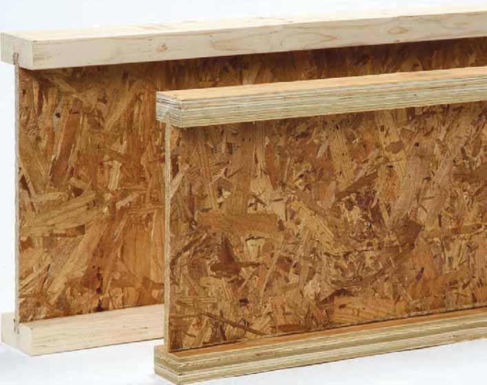
30 Engineered For Performance WHAT YOU DON T SEE MATTERS GP Lam LVL Wood I Beam Joists FiberStrong Rim Board Wood I Beam Joists GP Lam LVL Wood I Beam Joist GP Lam LVL FiberStrong Rim Board Wood I Beam Joist GP Lam LVL When it comes to floor joists, rim board, beams and headers, builders and contractors choose Georgia-Pacific engineered lumber for many reasons. Today s residential building trends call for large, open spaces and high ceilings, creating a demand for products that provide higher strength and greater stability over longer spans. Georgia-Pacific engineered lumber products are covered by a lifetime limited warranty. For complete warranty details, terms and conditions, please visit or call Georgia-Pacific Wood Products LLC 133 Peachtree Street Atlanta, Georgia This NGBS Green Certified mark is your assurance that a product is Home Innovation NGBS Green Certified for Resource Efficiency and Indoor Environmental Quality. Please visit Homeinnovation.com/Green for more information. Engineered lumber from Georgia-Pacific is made from wood that is sourced through a system that is third-party certified to the Sustainable Forestry Initiative (SFI ) procurement standard. Unless otherwise noted, all trademarks are owned by or licensed to Georgia-Pacific Wood Products LLC. APA Rated and Sturd-I-Floor are registered trademarks of APA-The Engineered Wood Association. TrussLok and FastenMaster are registered trademarks of Olympic Manufacturing Group, Inc. Simpson Strong-Tie is a registered trademark of Simpson Strong-Tie Company, Inc. USP Structural Connectors is a trademark of MiTek USA, Inc. Tough-Glass and Summit are trademarks owned by Atlas Roofing Corp. Monier is a trademark owned by Redland Engineering Limited. Gyp-Crete is a trademark owned by Maxxon Corporation. The Home Innovation NGBS Green Certified logo is a trademark of Home Innovation Research Labs. Sustainable Forestry Initiative and SFI are trademarks of Sustainable Forestry Initiative, Inc Georgia-Pacific Wood Products LLC. All rights reserved. Printed in the U.S.A. 1/14 TM Lit. Item #
WOOD I BEAM JOISTS PAGE 4 GEORGIA-PACIFIC WOOD PRODUCTS APR 2015 ENGINEERED LUMBER RESIDENTIAL GUIDE
 WOOD I BEAM JOISTS 4 GEORGIA-PACIFIC WOOD PRODUCTS APR 2015 ENGINEERED LUMBER RESIDENTIAL GUIDE Wood I Beam Joist features and benefits Engineered to deliver consistent stiffness and strength characteristics
Wood I Beam Joists GPI Series (LVL Flanges) WI Series (Lumber Flanges)
 WI Series (Lumber Flanges)") Wood I Beam Joists GPI Series (LVL Flanges) WI Series (Lumber Flanges) All Wood I Beam joists have an enhanced OSB web. Referenced dimensions are nominal and used for design purposes. Not all products
Wood I Beam Joists GPI Series (LVL Flanges) WI Series (Lumber Flanges) All Wood I Beam joists have an enhanced OSB web. Referenced dimensions are nominal and used for design purposes. Not all products
Residential Floor & Roof Systems Product Guide
 Engineered Lumber Residential Floor & Roof Systems Product Guide Edition IV Build on the strength of Today s home designs call for advanced building materials like Georgia-Pacific engineered lumber. The
LPI 56 Technical Guide
 LPI 56 Technical Guide Floor & Roof Applications Product Specifications & Design Values 2 Floor Tables 3 Uniform Floor Load (PLF) Tables: Simple s 4 Uniform Floor Load (PLF) Tables: Continuous s 5 Uniform
MAX-CORE I-JOIST DESIGN MANUAL-US
 MAX-CORE I-JOIST DESIGN MANUAL-US FRAMED BY QUALITY BUILT WITH SUCCESS OUR COMPANY At International Beams Inc. we take pride in providing our customers with premium quality products and services. Our full
Anchor bolts ASTM F1554, Gr. 36 Wide flange beams ASTM A992, Fy = 50 ksi Misc. structural steel ASTM A36, Fy = 36 ksi
 STRUCTURAL NOTES MATERIAL STRENGTHS Structural Steel Reinforcing Steel Concrete Masonry Structural Lumber Anchor bolts ASTM F1554, Gr. 36 Wide flange beams ASTM A992, Fy = 50 ksi Misc. structural steel
DIVISION: WOOD, PLASTICS AND COMPOSITES SECTION: WOOD I-JOISTS REPORT HOLDER: PACIFIC WOODTECH CORPORATION
 0 Most Widely Accepted and Trusted ICC-ES Evaluation Report ICC-ES 000 (800) 423-6587 (562) 699-0543 www.icc-es.org ESR-1225 Reissued 10/2017 This report is subject to renewal 10/2019. DIVISION: 06 00
ICBO Evaluation Service, Inc Workman Mill Road, Whittier, California *Revised April 2003
 PFC-5804* Reissued February 1, 2003 ICBO Evaluation Service, Inc. 5360 Workman Mill Road, Whittier, California 90601 www.icboes.org Filing Category: DESIGN Wood PACIFIC WOODTECH CORPORATION PWI JOISTS
INSTALLATION. US Version. Includes AJS 140 / 150 / 20 / 190 / 25 and VERSA-LAM BEAMS. Lifetime Guaranteed Quality and Performance
 The information in this document pertains to use in the UNITED STATES ONLY, Allowable Stress Design. Refer to the ALLJOIST Specifier Guide Canada for use in Canada, Limit States Design. INSTALLATION Guide
Including RedForm LVL, RedForm-I65, I90 and I90H Joists. Lightweight for Fast Installation. Compatible with Standard Framing
 FORMING AND SHORING Including RedForm LVL, RedForm-I65, I90 and I90H Joists Lightweight for Fast Installation Compatible with Standard Framing Available in Long Lengths Uniform and Predictable Resource-efficient
SECTION PLATE CONNECTED WOOD TRUSSES
 SECTION 06173 PLATE CONNECTED WOOD TRUSSES PART 1 GENERAL 1.01 SUMMARY A. Section Includes: 1. Shop fabricated wood trusses for roof and floor framing. 2. Bridging, bracing, and anchorage. B. Related Sections:
2.2E Parallam PSL Deep Beam
 #TJ-7001 SPECIFIER S GUIDE 2.2E Parallam PSL Deep Beam Featuring 20" 24" Deep Trus Joist Parallam PSL Beams Ideal for multi-family and light commercial applications Offers high strength and consistent
HILLSBOROUGH TOWNSHIP CODE ENFORCEMENT
 HILLSBOROUGH TOWNSHIP CODE ENFORCEMENT SAMPLE GUIDE FOR RESIDENTIAL DECKS revised 7 16 Call before you dig! 1 800 272 1000 New Jersey One Call. Utility Mark Out. THIS GENERIC GUIDE IS NOT ALL INCLUSIVE
Technical Data for. Headers. and Beams
 L A M I N A T E D V E N E E R L U M B E R Technical Data for Headers and Beams E A S T E R N E N G I N E E R E D W O O D P R O D U C T S OUR COMPANY Our total focus on engineered wood products and providing
Roseburg Framing System
 www.roseburg.com Roseburg EWP RESIDENTIAL Design and Installation Guide Limit States Design Roseburg Framing System RFPI -Joist RigidLam LVL RigidLam LVL Columns RigidRim Rimboard CANADA July 2017 quality
POST FRAME BUILDING STANDARDS
 CASS COUNTY, MISSOURI BUILDING CODES, ENVIRONMENTAL HEALTH AND ZONING DEPARTMENT 30508 S. West Outer Road, Harrisonville, MO 64701 P- (816) 380-8134 F- (816) 380-8130 POST FRAME BUILDING STANDARDS 201.3
2.2E Parallam PSL Deep Beam
 #TJ-7001 SPECIFIER S GUIDE 2.2E Parallam PSL Deep Beam Featuring 20" 24" Deep Trus Joist Parallam PSL Beams Ideal for multi-family and light commercial applications Offers high strength and consistent
R Code and Commentary for 2012 NC Residential Code final 03/06/13
 R602.10 Code and Commentary for 2012 NC Residential Code final 03/06/13 Commentary italicized and printed in red 1. Section R602.10 -- provides charging language for two simplified bracing approaches (isolated
DIVISION: WOOD, PLASTICS AND COMPOSITES SECTION: WOOD I JOISTS REPORT HOLDER: LOUISIANA PACIFIC CORPORATION
 0 Most Widely Accepted and Trusted ICC ES Report ICC ES 000 (800) 423 6587 (562) 699 0543 www.icc es.org ESR 1305 Reissued 08/2016 This report is subject to renewal 08/2018. DIVISION: 06 00 00 WOOD, PLASTICS
The better way to build TM. Installation Manual FOUNDATION SIPs & FROST WALLS SIPs
 The better way to build TM Installation Manual FOUNDATION SIPs & FROST WALLS SIPs November 2016 PWF FOUNDATION & FROST WALL SIPs Installation Manual Table of Contents Topics General Requirements....................................
Dead Load Weight of Roof Trusses. Dead Load Weight of Floor Trusses
 Dead Load Weight of Roof Trusses Top Chord Bottom Chord Webs Weight per Lineal Foot (plf) 2x4 2x4 2x4 4.3 2x4 2x8 2x4 5.6 2x6 2x4 2x4 4.8 2x6 2x6 2x4 5.5 2x6 2x6 2x6 6.2 2x6 2x8 2x4 5.9 2x6 2x10 2x4 6.6
TJI Pro 120TS Joists Featuring the Silent Floor System for Residential Applications
 TJI Pro Joists Featuring the Silent Floor System for Residential Applications Environmentally Responsible Uniform and Predictable Resists Bowing, Twisting and Shrinking Lightweight for Fast Installation
INSULATION RETROFIT DESIGN ENERGY SOLUTIONS CENTRE YUKON GOVERNMENT
 INSULATION RETROFIT DESIGN ENERGY SOLUTIONS CENTRE YUKON GOVERNMENT MAY 2009 prepared by N. A. JACOBSEN, P.Eng. CIVIL ENGINEERING CONSULTANT Whitehorse, Yukon ENERGY SOLUTIONS CENTRE YUKON GOVERNMENT MAY
CHAPTER 3 BUILDINGS WITH WOOD FRAMED EXTERIOR WALLS 301 SCOPE
 CHAPTER 3 BUILDINGS WITH WOOD FRAMED EXTERIOR WALLS WOOD CHAPTER 3 301 SCOPE This chapter prescribes construction requirements for buildings where all exterior walls above the foundation are wood framed
LVL Product Guide 2.0E LVL 1.5E LVL
 LVL Product Guide 2.0E LVL 1.5E LVL Our Company Anthony Forest Products Company, a family-owned business founded in 1916, is headquartered in El Dorado, Arkansas. The company operates a southern pine lumber
FACT SHEET #2 DECK INFORMATION
 Borough of Doylestown Building and Zoning Department 57 West Court Street, Doylestown, PA 18901 215.345.4140 FACT SHEET #2 DECK INFORMATION BACKGROUND The provisions of the PAUCC. ICC Property Maintenance
Structural Tests and Special Inspections Form. Inspection of Fabricators (1704.2)
") Inspection of Fabricators (1704.2) Furnish inspection reports (1704.2.1) - Fabricators that have not been approved Provide a Certificate of Compliance (1704.2.2) - Approved Fabricators Steel Construction
Inspection of Fabricators (1704.2) Furnish inspection reports (1704.2.1) - Fabricators that have not been approved Provide a Certificate of Compliance (1704.2.2) - Approved Fabricators Steel Construction
LP OSB Sheathing & Structural 1 Sheathing
 Rated OSB Sheathing Roof Panels Span Ratings Max. Live Load Thickness Span Rating for Roofs (lbs)** 3/8" 24/0 30 7/16" 24/16 40 15/32" 32/16 70 1/2" 32/16 70 19/32" 40/20 130 23/32" 48/24 175 1-1/8" 48
Administrative Changes
 Revised 11/29/06 Knox County Residential Building Codes Significant Changes From The 1995 CABO One And Two Family Dwelling Code To The 2006 International Residential Code All one and two family dwellings
O PEN J OIST Installation Guide
 Friendly Field Adjustability US Edition O PEN J OIST Installation Guide Built by Peace of mind underfoot www.openjoisttriforce.com Contents Adjustment...II Identification...1 Safety Precautions...1 Storage
City of Hughson Building Safety Division 7018 Pine Street Hughson, CA (209)
") City of Hughson Building Safety Division 7018 Pine Street Hughson, CA 95326 (209) 883-4054 RESIDENTIAL ATTACHED PATIO COVERS Patio covers are one story roofed structures not more than 12 feet above grade,
City of Hughson Building Safety Division 7018 Pine Street Hughson, CA 95326 (209) 883-4054 RESIDENTIAL ATTACHED PATIO COVERS Patio covers are one story roofed structures not more than 12 feet above grade,
Wood Design for Architects: Engineering for the Non-engineer. AIA Statement
 Wood Design for Architects: Engineering for the Non-engineer AIA Statement The Wood Products Council is a Registered Provider with The American Institute of Architects Continuing Education Systems (AIA/CES).
Open-Web Trusses. Including Red-L, Red-W, Red-S, Red-M and Red-H Trusses. Design Flexibility. Outstanding Strength-to-Weight Performance
 Open-Web Trusses Including Red-L, Red-W, Red-S, Red-M and Red-H Trusses Download your free copy at RedBuilt.com. Specify Open-Web trusses for your next project using RedSpec single-member sizing software.
GARAGES/ONE-STORY City of Grand Rapids Building Safety Division
 GARAGES/ONE-STORY City of Grand Rapids Building Safety Division 218-326-7601 www.cityofgrandrapidsmn.com This handout is intended only as a guide and is based in part on the 2015 Minnesota State Building
SECTION GYPSUM BOARD
 SECTION 09250 GYPSUM BOARD PART 1GENERAL 1.1 SUMMARY A. Related Documents: General and Supplementary Conditions of the Contract, Division 1 - General Requirements, and Drawings are collectively applicable
DIVISION: WOOD, PLASTICS AND COMPOSITES SECTION: STRUCTURAL PANELS REPORT HOLDER: ENERCEPT, INC.
 0 Most Widely Accepted and Trusted ICC ES Evaluation Report ICC ES 000 (800) 423 6587 (562) 699 0543 www.icc es.org ESR 1780 Reissued 11/2017 This report is subject to renewal 11/2019. DIVISION: 06 00
LAMINATED VENEER LUMBER
 LAMINATED VENEER LUMBER Kerto LVL Beams, Headers, Rafters and Columns for Floor and Roof Applications. USA VERSION KERTO LAMINATED VENEER LUMBER TABLE OF CONTENTS Design Properties... 2 Allowable Uniform
Introducing TJ Insulated Structural Framing Components
 #TJ-9009 SPECIFIER S GUIDE TJ INSULATED HEADERS, RIM BoaRD, AND CORNERS Introducing TJ Insulated Structural Framing Components Helps meet the 2011 Federal Energy Star Homes and 2009 International Energy
RESIDENTIAL WOOD DECK CONSTRUCTION GUIDE
 RESIDENTIAL WOOD DECK CONSTRUCTION GUIDE Based on The 2009 Michigan Residential Code Revised September 25, 2014 Wood Deck Construction in accordance with this guide is acceptable in the following Michigan
EXCEL Medical Waste - Equipment Installation Section SECTION GYPSUM BOARD
 SECTION 09 29 00 GYPSUM BOARD PART 1 - GENERAL 1.1 DESCRIPTION This section specifies installation and finishing of gypsum board. 1.2 RELATED WORK A. Installation of steel framing members for walls, partitions,
4 EXTREME FOUNDATION PANELS
 4 EXTREME FOUNDATION PANELS For House Crawl Space On Concrete Footings 1. The type of soil is a factor in determining foundation construction details such as footing design, backfill, and drainage provisions.
Gold Bond BRAND Gypsum Sheathing
 BRAND 09 06 29 16 00/NGC 43/NGC brand is a moisture-resistant sheathing installed on the outside of exterior framing as a substrate for exterior claddings. It is manufactured with a treated water-resistant
ROOFING APPLICATION STANDARD (TAS) No. 102(A)-95
 No. 102(A)-95") ROOFING APPLICATION STANDARD (TAS) No. 102(A)-95 TEST PROCEDURE FOR STATIC UPLIFT RESISTANCE OF MECHANICALLY ATTACHED, CLIPPED, RIGID, ROOF SYSTEMS (For Methods of Mechanical Attachment Excluding Clips,
ROOFING APPLICATION STANDARD (TAS) No. 102(A)-95 TEST PROCEDURE FOR STATIC UPLIFT RESISTANCE OF MECHANICALLY ATTACHED, CLIPPED, RIGID, ROOF SYSTEMS (For Methods of Mechanical Attachment Excluding Clips,
Specifications. Materials and Fabrication. Physical Properties. Environmental Impact. Sizes. Installation - General Requirements.
 Specifications Materials and Fabrication Physical Properties LP FlameBlock Fire-Rated OSB Sheathing panels are made of oriented strand board (OSB) with a fire-resistant, cementitious coating (Pyrotite
130 MPH EXPOSURE B WFCM GUIDE. Guide to Wood Frame Construction in High Wind Areas for One- and Two-Family Dwellings 2015 EDITION
 130 MPH EXPOSURE B WFCM GUIDE Guide to Wood Frame Construction in High Wind Areas for One- and Two-Family Dwellings 2015 EDITION Updates and Errata While every precaution has been taken to ensure the accuracy
Details for Exterior Brick Masonry Veneer Supported by Metal Plate Connected Wood Trusses
 Details for Exterior Brick Masonry Veneer Supported by Metal Plate Connected Wood Trusses Released May 20, 2009 Updated March 9, 2011 Introduction: Wood frame structures with attached brick masonry veneer
TYPICAL BEARING WALL FRAMING
 BASIC WOOD FRAMING City of Grand Rapids Building Safety Division 218-326-7601 www.grandrapidsmn.org This handout is intended only as a guide and is based in part on the 2007 Minnesota State Building Code,
SECTION GYPSUM BOARD ASSEMBLIES
 SECTION 09 21 16 GYPSUM BOARD ASSEMBLIES PART 1 GENERAL 1.1 SECTION INCLUDES A. Metal stud wall and ceiling framing, 20 gauge. B. Metal channel suspended ceiling framing. C. Gypsum board. D. Gypsum sheathing.
CH. 9 WOOD CONSTRUCTION
 CH. 9 WOOD CONSTRUCTION PROPERTIES OF STRUCTURAL LUMBER Grading Load carrying capacity effected by: - Size and number of knots, splits & other defects - Direction of grain - Specific gravity of wood Grading
2003 International Residential Building Code
 2003 International Residential Building Code Section R305 Ceiling Height Habitable rooms, hallways, corridors, bathrooms, toilet rooms, laundry rooms and basements shall have a ceiling height of not less
CARROLL COUNTY BUREAU OF PERMITS AND INSPECTIONS RESIDENTIAL CODE COMPLIANCE GUIDELINES FOR DECKS
 CARROLL COUNTY BUREAU OF PERMITS AND INSPECTIONS RESIDENTIAL CODE COMPLIANCE GUIDELINES FOR DECKS Code Reference: Chapter 97, Code of Public Local Laws and Ordinances of Carroll County and The International
The Ashland Project. Total Area: 1,778 Sq.Ft. 3 Bedroom, 2 Bath, 2 Car Garage
 The Ashland Project Total Area: 1,778 Sq.Ft. 3 Bedroom, 2 Bath, 2 Car Garage The garage and bedroom extend from the front of this three bedroom home, drawing you visually into the entryway. Brick and stucco
WFCM 130 MPH GUIDE EXPOSURE B WOOD FRAME CONSTRUCTION MANUAL GUIDE TO WOOD CONSTRUCTION IN HIGH WIND AREAS FOR ONE- AND TWO-FAMILY DWELLINGS
 130 MPH EXPOSURE B GUIDE WFCM WOOD FRAME CONSTRUCTION MANUAL GUIDE TO WOOD CONSTRUCTION IN HIGH WIND AREAS FOR ONE- AND TWO-FAMILY DWELLINGS A F & P A American Forest & Paper Association American Wood
On Cold-Formed Steel Construction. Light Gauge Steel Engineers Association Washington, D.C Toll Free (866)
") TECHNICAL NOTE On Cold-Formed Steel Construction $5.00 Light Gauge Steel Engineers Association Washington, D.C. 20005 Toll Free (866) 465-4732 www.lgsea.com DESIGN OF BY-PASS SLIP CONNECTORS IN COLD-FORMED
TECHNICAL NOTE On Cold-Formed Steel Construction $5.00 Light Gauge Steel Engineers Association Washington, D.C. 20005 Toll Free (866) 465-4732 www.lgsea.com DESIGN OF BY-PASS SLIP CONNECTORS IN COLD-FORMED
SCREEN PORCHES 101 DEVELOPMENT RESOURCES, INC Permit Requirements
 SCREEN PORCHES 101 DEVELOPMENT RESOURCES, INC. 320-226.5189 www.101developmentresources.com While every attempt has been made to insure the correctness of this handout, no guarantees are made to its accuracy
Attachment of Residential Deck Ledger to Metal Plate Connected Wood Truss Floor Systems
 to Metal Plate Connected Wood Truss Floor Systems Structural Building Components Association (SBCA) February 17, 2015 Revised August 15, 2017 SBCA is an APPROVED SOURCE This research report is based on
Inspection of New One- and Two- Family Dwellings
 Building Safety Division 8500 Santa Fe Drive Overland Park, KS 66212 (913) 895-6225 Fax (913) 895-5016 Email: permitservices@opkansas.org Inspection of New One- and Two- Family Dwellings Planning and Development
Joint Evaluation Report ICC-ES (800) (562)
 (562)") 0 Joint Evaluation Report ICC-ES (800) 423-6587 (562) 699-0543 www.icc-es.org 000 ESR-1262 Reissued 01/2018 This report is subject to renewal 01/2019. DIVISION: 06 00 00 DIVISION NAME SECTION: 06 17 33
0 Joint Evaluation Report ICC-ES (800) 423-6587 (562) 699-0543 www.icc-es.org 000 ESR-1262 Reissued 01/2018 This report is subject to renewal 01/2019. DIVISION: 06 00 00 DIVISION NAME SECTION: 06 17 33
RESIDENTIAL WOOD DECK CONSTRUCTION GUIDE
 RESIDENTIAL WOOD DECK CONSTRUCTION GUIDE Based on the 2015 Michigan Residential Code Revised May 17, 2016 The Following Organizations Support the use of this Guide: The details in this document apply to
Temporary Construction Loads Over I-Joist Roofs And Floors
 T E C H N I C A L N O T E Temporary Construction Loads Over I-Joist Roofs And Floors Number J735C July 2012 During construction of light-frame structures it is common to see relatively heavy loads placed
Report on Structural Stability of Engineered Lumber in Fire Conditions
 Report on Structural Stability of Engineered Lumber in Fire Conditions Prepared by: Project Number: 07CA42520 File Number: NC9140 Underwriters Laboratories Inc. 333 Pfingsten Road, Northbrook, IL 60062
KERTO HEADER INSULATED LVL HEADER 31/2", 51/2" 3 1/2" AND 5 1/2" THICKNESSES DESIGN VALUES USA
 KERTO USA page 1/12 KERTO INSULATED LVL 3 1/2" AND 5 1/2" THICKNESSES DESIGN VALUES USA KERTO USA page 2/12 TABLE OF CONTENTS 3 Specification Guide 4 About Kerto Header 5 Insulation Values 6 Maximum Loads
SDPWS. Special Design Provisions for Wind & Seismic 2015 EDITION
 SDPWS Special Design Provisions for Wind & Seismic 2015 EDITION ANSI/AWC SDPWS-2015 Approval date September 8, 2014 Updates and Errata While every precaution has been taken to ensure the accuracy of this
WIND & SEISMIC 2008 EDITION ASD/LRFD WITH COMMENTARY. American Forest & Paper Association. American Wood Council ANSI/AF&PA SDPWS-2008
 2008 EDITION ANSI/AF&PA SDPWS-2008 Approval Date: August 4, 2008 ASD/LRFD WIND & SEISMIC Special Design Provisions for Wind and Seismic WITH COMMENTARY American Forest & Paper Association American Wood
Quality Inspection 8618 London Heights San Antonio, TX Phone: (210)
") Quality Inspection 8618 London Heights San Antonio, TX 78254 Phone: (210) 240-0476 PRE DRYWALL INSPECTION REPORT Prepared For: DELETED (Name of Client) Concerning: DELETED, San Antonio, TX 78258 (Address
Quality Inspection 8618 London Heights San Antonio, TX 78254 Phone: (210) 240-0476 PRE DRYWALL INSPECTION REPORT Prepared For: DELETED (Name of Client) Concerning: DELETED, San Antonio, TX 78258 (Address
Structural Inspection
 General: Background: An inspection and structural analysis have been performed for the purpose of evaluating the buildings structural systems and components. A full set of structural drawings was utilized
Thermasheath -3. Insulation for the Building Envelope ROOF WALL SPECIALTY
 Insulation for the Building Envelope ROOF WALL SPECIALTY PRODUCT DESCRIPTION Rmax Thermasheath-3 is an energy-efficient thermal insulation board composed of a closed-cell polyisocyanurate (polyiso) foam
DIVISION: WOOD, PLASTICS AND COMPOSITES SECTION: WOOD I JOISTS REPORT HOLDER: REDBUILT LLC
 0 Most Widely Accepted and Trusted ICC ES Evaluation Report ICC ES 000 (800) 423 6587 (562) 699 0543 www.icc es.org ESR 2994 Reissued 08/2017 This report is subject to renewal 08/2019. DIVISION: 06 00
The following are details of the code requirements of the 2015 International Residential Code for single-story decks.
 The following are details of the code requirements of the 2015 International Residential Code for single-story decks. The 2015 International Residential Code Section R507 contains additional information
CONTRACT NUMBER: W912DQ-08-C % CORRECTED DESIGN 28 JULY 2008
 SECTION 092900 - GYPSUM BOARD 1.1 SUMMARY A. This Section includes the following: 1. Interior gypsum board. 2. Tile backing panels. B. Related Sections include the following: 1. Division 06 Section "Rough
Minimum Requirements For One & Two Family Structures FBC 6 th Edition (2017)
") Pinellas County Building Department Reviewed : Date: Phone: Owner s Name: Permit Number: CB_ - Property Address: Contractor: Phone: Minimum Requirements For One & Two Family Structures FBC 6 th Edition
Pinellas County Building Department Reviewed : Date: Phone: Owner s Name: Permit Number: CB_ - Property Address: Contractor: Phone: Minimum Requirements For One & Two Family Structures FBC 6 th Edition
Heel Blocking Requirements and Capacity Analysis. Overview Revised 3/22/2017
 Heel Blocking Requirements and Capacity Analysis Overview Revised 3/22/2017 SBCA has been the voice of the structural building components industry since 1983, providing educational programs and technical
TER No Cultured Stone & ProStone Applications Over Continuous Insulation
 Cultured Stone & ProStone Applications Over Continuous Insulation TER No. 1302-01 Boral Stone Products LLC 200 Mansell Court East, Suite 310 Roswell, GA 30076 419-318-5345 949-341-8890 (fax) chris.hines@boral.com
APPLICATION AND FINISHING OF GYPSUM PANEL PRODUCTS
 GYPSUM ASSOCIATION SPECIFICATIONSI I 6525 Belcrest Road, Suite 480, Hyattsville MD 20782 APPLICATION AND FINISHING OF GYPSUM PANEL PRODUCTS GA-216-2013 This document may be revised or withdrawn from circulation
ESR-2894 Reissued April 2014 This report is subject to renewal April 1, 2016.
 ICC-ES Evaluation Report ESR-894 Reissued April 04 This report is subject to renewal April, 0. www.icc-es.org (800) 4-87 () 99-04 A Subsidiary of the International Code Council DIVISION: 07 00 00 THERMAL
NATIONAL GYPSUM COMPANY Wood Frame Walls And Ceilings Single- And Double-Layer Construction
 Walls And Ceilings Single- And Double-Layer Construction 09 9 00/NGC Single-Layer Construction The single-layer construction system consists of a single layer of Gold Bond brand Gypsum Board applied to
COOK COUNTY ILLINOIS CONTRACT FOR WORK DOCUMENT NO Countywide Warehouse and Records Storage Center Hawthorne Project TKB No.
 SECTION 092900 GYPSUM BOARD PART 1 - GENERAL 1.1 RELATED DOCUMENTS A. Drawings and general provisions of the Contract, including General and Supplementary Conditions and Division 01 Specification Sections,
SJI Code of Standard Practice
 Standard Practice CODE OF STANDARD PRACTICE FOR STEEL JOISTS AND JOIST GIRDERS SECTION 1 GENERAL 1.1 SCOPE Adopted by the Steel Joist Institute April 7, 1931 Revised to May 18, 2010 - Effective December
STEEL STUD, TRIMS AND ACCESSORIES FOR DRYWALL CONSTRUCTION MONTREAL TORONTO CALGARY EDMONTON VANCOUVER THE STRENGTH WITHIN
 STEEL STUD, TRIMS AND ACCESSORIES FOR DRYWALL CONSTRUCTION MONTREAL TORONTO CALGARY EDMONTON VANCOUVER THE STRENGTH WITHIN STEEL STUD AND TRACK FOR DRYWALL PARTITIONS TAKE ADVANTAGE OF THE SAVINGS IN TIME
Prescriptive Residential Wood Deck Construction Guide Based on the 2012 International Residential Code
 Prescriptive Residential Wood Deck Construction Guide Based on the 2012 International Residential Code Where applicable, provisions and details contained in this document are based on the International
DIVISION: THERMAL AND MOISTURE PROTECTION SECTION: METAL ROOF PANELS SECTION: METAL WALL PANELS REPORT HOLDER:
 0 Most Widely Accepted and Trusted ICC ES Evaluation Report ICC ES 000 (800) 4 6587 (562) 699 0543 www.icc es.org ESR 3152 Reissued 08/2017 This report is subject to renewal 08/2018. DIVISION: 07 00 00
Chapter 2 EARTHQUAKE-RESISTANCE REQUIREMENTS
 Chapter 2 EARTHQUAKE-RESISTANCE REQUIREMENTS This chapter explains the International Residential Code s (IRC s) general earthquake-resistance requirements as well as specific IRC requirements concerning
SECTION COLD-FORMED METAL FRAMING
 SECTION 05400 PART I - GENERAL 1.01 DESCRIPTION A. Scope: Work of this Section shall include all materials and installation necessary to provide all cold formed metal framing. B. This Section includes:
BEARING METAL STUD FRAMING
 L-1 Section 05410 Long Form Specification LOAD BEARING METAL STUD FRAMING This section includes axially loaded steel studs, with unique slotted top channels, usually of 0.91, 1.2 and 1.5 mm (16, 18, or
Warranty Certificate. Allied Structural Materials, LLC. Our Warranty. warrants
 LVL 2.0E/2900Fb Allied Structural Materials, LLC Allied Structural Materials (ASM) is the exclusive national manufacturer s representative for Ultralam LVL in the USA. Having decades of experience in marketing
Residential Detached Garage Handout
 Residential Detached Garage Handout Getting Started 1. Please read this handout in its entirety. If you have specific questions after reading the handout, please contact the Altoona Building Department
BUILDING BULLETIN One and Two Family Dwellings Decks and Residential Access Ramps
 BUILDING BULLETIN One and Two Family Dwellings Decks and Residential Access Ramps City of Virginia Beach Building Permits & Inspections Updated 4/30/09 Table of Contents I. Introduction... 1 II. Tips
TRAINING. To access the Truss Store go to any of the computers at the building materials desk and click on Vendor Catalogs = > Truss Store.
 To access the Truss Store go to any of the computers at the building materials desk and click on Vendor Catalogs = > Truss Store. The Truss Store was designed for ease of use by team members and guests
DIVISION: WOOD, PLASTICS AND COMPOSITES SECTION: SHOP FABRICATED WOOD TRUSSES REPORT HOLDER: BARRETTE STRUCTURAL DISTRIBUTION, INC.
 0 Most Widely Accepted and Trusted ICC ES Report ICC ES 000 (800) 43 6587 (56) 699 0543 www.icc es.org ESR 999 Reissued 0/07 This report is subject to renewal 0/08. DIVISION: 06 00 00 WOOD, PLASTICS AND
CITY OF CEDAR FALLS DEPARTMENT OF DEVELOPMENTAL SERVICES INSPECTION SERVICES DIVISION PHONE Residential Accessory Structures
 CITY OF CEDAR FALLS DEPARTMENT OF DEVELOPMENTAL SERVICES INSPECTION SERVICES DIVISION PHONE - 268-5161 Residential Accessory Structures This information has been compiled for the benefit of any person
Guide to Attaching Exterior Wall Coverings through Foam Sheathing to Wood or Steel Wall Framing
 Guide to Attaching Exterior Wall Coverings through Foam Sheathing to Wood or Wall Framing Released September 20, 2010 Updated December 4, 2012 Note: Tables for cladding attachments to wood framing have
Evaluation Report CCMC R LP SolidStart LVL
 Evaluation Report CCMC 11518-R LP SolidStart LVL MASTERFORMAT: 06 17 10.01 Evaluation issued: 1987-06-03 Revised: 2015-01-13 Re-evaluation due: 2018-04-27 1. Opinion It is the opinion of the Canadian Construction
DIVISION: WOOD, PLASTICS AND COMPOSITES SECTION: WOOD I-JOISTS REPORT HOLDER: WEYERHAEUSER
 0 Most Widely Accepted and Trusted ICC-ES Evaluation Report ICC-ES 000 (800) 4-6587 (56) 699-054 www.icc-es.org ESR-5 Reissued 05/07 This report is subject to renewal 05/09. DIVISION: 06 00 00 WOOD, PLASTICS
Residential Decks 1 & 2 Family Dwellings and Townhouses City of Owatonna BUILDING DEPARTMENT
 Residential Decks 1 & 2 Family Dwellings and Townhouses City of Owatonna BUILDING DEPARTMENT 507-444-4370 www.ci.owatonna.mn.us This handout is intended only as a guide and is based in part on the 2007
NOVABRIK MORTARLESS CONCRETE BRICK VENEER SPECIFICATION. MASTERFORMAT SECTION (Mortarless Concrete Brick Veneer)
") NOVABRIK MORTARLESS CONCRETE BRICK VENEER SPECIFICATION MASTERFORMAT SECTION 04818 (Mortarless Concrete Brick Veneer) Spec_USA_En_18102005.doc 12/1/2005 Novabrik Page 2 Section 04818 NOVABRIK MORTARLESS
NOVABRIK MORTARLESS CONCRETE BRICK VENEER SPECIFICATION MASTERFORMAT SECTION 04818 (Mortarless Concrete Brick Veneer) Spec_USA_En_18102005.doc 12/1/2005 Novabrik Page 2 Section 04818 NOVABRIK MORTARLESS
TECHNICAL NOTE On Cold-Formed Steel Construction
 TECHNICAL NOTE On Cold-Formed Steel Construction $5.00 6a 1996 Light Gauge Steel Engineers Association Washington, D.C. Toll-Free: 1 (866) 465-4732 www.lgsea.com DESIGN GUIDE FOR PERMANENT BRACING OF COLD-FORMED
Considerations for Outof-Plane. Design
 Considerations for Outof-Plane Wall and Uplift Design WoodWorks Texas Workshops December, 2016 Overview Uplift Wall Design Wind Loads Wind loads acting on buildings are modeled as uniform surface loads.
ISO Types 1-6: Construction Code Descriptions
 ISO 1 Frame (combustible walls and/or roof) Typically RMS Class 1 Wood frame walls, floors, and roof deck Brick Veneer, wood/hardiplank siding, stucco cladding Wood frame roof with wood decking and typical
COFS Mission. AISI Standards Hierarchy. North American Standards for Cold-Formed Steel Framing. Member versus System Design. Specification 10/21/2016
 COFS Mission North American Standards for Cold-Formed Steel Framing Roger LaBoube, Ph.D., P.E. Curators Distinguished Teaching Professor Emeritus Director, Wei-Wen Yu Center for Cold-Formed Steel Structures
Building Guide. Colorado Chapter of the International Code Council
 12/29/16 Building uide Colorado Chapter of the International Code Council How to Use this uide Check with your jurisdiction regarding type of submittal (paper or electronic) and for additional requirements.draw