SAND POINT CITY DOCK REPLACEMENT ALTERNATIVES ANALYSIS REPORT
|
|
|
- Dale Jordan
- 6 years ago
- Views:
Transcription


1 SAND POINT CITY DOCK REPLACEMENT ALTERNATIVES ANALYSIS REPORT Prepared for: City of Sand Point 3380 C Street, Suite 205 Anchorage, Alaska Prepared by: PND Engineers, Inc W. 36 th Avenue Anchorage, Alaska July 22, 2015
2 PND Engineers, Inc. Sand Point City Dock Replacement Alternatives Analysis Report TABLE OF CONTENTS INTRODUCTION SITE CONDITIONS REPLACEMENT DOCK ALTERNATIVES Alternative 1: OPEN CELL SHEET PILE Bulkhead Alternative 2: Single Pile Supported Concrete Platform Dock Alternative 2a: Dual Pile Supported Concrete Platform Dock Alternative 3: Tied Back Combination Wall System COST ESTIMATES Basis of Estimates ROM Cost Estimates CONCLUSIONS AND RECOMMENDATIONS APPENDICES i
3 PND Engineers, Inc. Sand Point City Dock Replacement Alternatives Analysis Report LIST OF FIGURES Figure 1. SECTION: OPEN CELL SHEET PILE BULKHEAD... 3 Figure 2. SECTION: PILE SUPPORTED CONCRETE PLATFORM DOCK... 5 Figure 3. SECTION: TIED BACK COMBI WALL SYSTEM... 8 LIST OF TABLES Table 1. COST ESTIMATES Table 2. SUMMARY OF ALTERNATIVE DESIGNS: ADVANTAGES AND DISADVANTAGES LIST OF APPENDICES Appendix A. Plan and Section Drawings for (4) Replacement Dock Concepts Appendix B. Cost Estimates for (3) Replacement Dock Concepts (includes material takeoffs) Appendix C. Schedules for (3) Replacement Dock Concepts Appendix D. Existing City Dock Drawings ii
4 PND Engineers, Inc. Sand Point City Dock Replacement Alternatives Analysis Report EXECUTIVE SUMMARY This report has been prepared for the City of Sand Point (City), Alaska, with the purpose of providing an analysis of alternatives for replacement of the City Dock. Built in 1981, the existing City Dock is a steel pile supported, concrete deck, platform dock that was designed by PND Engineers, Inc. (PND, under the name Peratrovich & Nottingham at the time). The dock is currently utilized for receiving shipment of conventional and containerized cargo and as a terminal for the Alaska Marine Highway System. The dock has outlived its 30 year design life and requires replacement. The City seeks to obtain funding for replacement of this dock. To support the efforts of the City, PND is providing the following: Preliminary design concepts for (3) replacement dock concepts with a modification of one of the concepts also presented Material takeoffs and cost estimates for (3) replacement dock concepts (see Appendix B) Alternatives analysis and recommendations Three primary alternative concepts for the new replacement dock were examined: an OPEN CELL SHEET PILE (OCSP ) bulkhead, a single pile supported concrete platform dock, and a tied back combination wall (or combi wall) system. A fourth alternative investigates a dual pile supported concrete platform dock concept that will work in conjunction with the existing dock. A Material takeoff and cost estimate corresponding to this concept was not analyzed at this time; however, costs are expected to be similar to the pile supported dock option. Preliminary designs include analyses of dead loads, vehicular live loads, uniform surcharge live loads, soil loads, phreatic water loads, and seismic loads. In addition to the structural analysis, dock concepts were reviewed for performance, constructability, permitting concerns, and Rough Order of Magnitude (ROM) cost. Advantages and disadvantages in each of these areas were considered for each dock concept. A summary of the ROM costs is shown in the table below. ALTERNATIVE ROM COST OPEN CELL SHEET PILE Bulkhead $8,497,000 Single Pile Supported Concrete Platform Dock $9,511,000 Tied Back Combination Wall System $13,411,000 *Note: Cost estimate for dual pile supported concrete platform dock concept was not performed The recommended replacement concept for the City Dock is an OCSP bulkhead. This option has many advantages over the other two primary options considered. Most significantly, the OCSP bulkhead is the least expensive alternative, has a relatively short construction time, and is expected to perform well under both service and extreme loads. Alternatively, should the dock s finished surface (concrete or gravel) be a major consideration, and if relative ease of permitting is deemed to be valuable, the pilesupported option may offer an attractive alternative at a marginally higher cost. iii
5 PND Engineers, Inc. Sand Point City Dock Replacement Alternatives Analysis Report INTRODUCTION As stated in the Executive Summary, we understand that the City is seeking to obtain funding for replacement of the existing City Dock, which has outlived its 30 year design life. PND has reviewed the existing dock for applicability to the current design codes and has determined the dock requires replacement. The existing dock is 200 feet long by 60 feet wide and services vessels with drafts up to 30 feet. The replacement dock will be of similar size to the existing dock, but with greater expected performance under both service and extreme loads. It will be designed to support shipping and receiving of commercial goods, service industry goods and will function as a terminal for the ferry Tustumena and its longer replacement vessel. PND performed preliminary design on four alternatives for a replacement dock: 1. OPEN CELL SHEET PILE bulkhead 2. Single Pile supported concrete platform dock a. Dual Pile supported concrete platform dock 3. Tied back combination wall system This report is divided into four sections. Section 1 includes discussion of the existing site conditions. Section 2 discusses the four proposed dock replacement concepts, including advantages and disadvantages for each option. Section 3 includes the cost estimates and related discussion. Section 4 is the conclusions and recommendations. 1
6 PND Engineers, Inc. Sand Point City Dock Replacement Alternatives Analysis Report 1.0 SITE CONDITIONS Based on the limited soils information available from existing drawings and PND s experience on the Alaska Peninsula and Aleutian Islands, we anticipate the soils in the project vicinity to be silty sand and gravel. Existing mudline is overlain by a 12 minus rock fill at the dock location. The fill slopes 1.5:1 (horizontal: vertical) from approximately the top of existing dock to the dock waterside face. The proposed primary design options all assume that the existing dock will be demolished and the replacement dock will be placed in approximately the same location. Therefore, the footprint of the new dock will be approximately equal to the existing dock. PND acknowledges the option to keep the existing dock in service while the replacement dock is being built; however, the implications of this have not been explored in detail. If the replacement dock is built adjacent to the existing dock, all three alternative replacement dock options will have to contend with driving piles (sheet piles, pipe piles, or Peine beam box piles) through the existing armor rock on the causeway slope or removing the armor rock to mitigate risk and may require additional permitting effort. Limited survey and bathymetry information is available for this preliminary phase of design. Therefore, material quantities, sizes, duration of construction, and costs are subject to change based on additional survey data. The selected design alternative will be subject to change based on geotechnical considerations that are not part of this report. 2
 bulkhead option will be constructed from flat steel sheet piles driven in connected semi circular or scalloped arcs to")


7 PND Engineers, Inc. Sand Point City Dock Replacement Alternatives Analysis Report 2.0 REPLACEMENT DOCK ALTERNATIVES 2.1 Alternative 1: OPEN CELL SHEET PILE Bulkhead The OPEN CELL SHEET PILE (OCSP ) bulkhead option will be constructed from flat steel sheet piles driven in connected semi circular or scalloped arcs to form face and end cells. The sheet piles will be driven straight back from the face cells to form tailwalls that tie back/support the face. At the upland end of the tailwalls, anchor piles consisting of a half piece of flat sheet pile welded to an H pile will be driven to provide added resistance to the tailwall. The dock face will be 220 feet long and consist of a double H pile cap beam welded to the top of the face cell sheet piles to form a straight dock face. The total dock width will be approximately 250 feet between apexes of the end cells. The dock will extend seaward from the causeway approximately the same distance as the existing pile supported dock (i.e., dock face will be at approximately the same water depth). See Figure 1. See Appendix A for a plan and section drawing of this concept. Figure 1. SECTION: OPEN CELL SHEET PILE BULKHEAD The surface of the dock will be a crushed gravel finish course. Alternatively, cast in place concrete surfacing may be installed across a large portion of the dock or in discrete sections. 3
8 PND Engineers, Inc. Sand Point City Dock Replacement Alternatives Analysis Report Similar to the other dock options, the OCSP dock will have a heavy duty fender system on the face of the dock and two mooring dolphins accessible by catwalks from the dock. The new dolphins are positioned in approximately the same location as the existing mooring dolphins. Construction time for the OCSP option is estimated at 120 days (see Appendix C for a draft construction schedule). Construction involves driving sheet piles, placing and compacting fill. Construction equipment required for an OCSP dock is similar to that of a tied back sheet pile or combi wall system and is similar in size and quantity to the pile supported dock. The construction of the OCSP bulkhead requires placement of fill material below the high tide line (HTL), requiring regulatory review by the US Army Corps of Engineers. Installation of the piles will create elevated noise levels that could affect endangered species within the vicinity of the project. Consultations with agencies such as the US Fish and Wildlife Service (USFWS) and the National Marine Fisheries Service (NMFS), required by Section 7 of the Endangered Species Act, will result in additional permit conditions like hazard radii and marine mammal observers. OPEN CELL SHEET PILE Bulkhead Advantages: OCSP bulkhead is more economical than the other dock options considered. OCSP bulkhead concept has a higher reserve load capacity compared to the concrete platform dock or the tied back combi wall options. Design has fewer fabricated components compared to the concrete platform dock or the tied back combi wall options. Sheet piles may be installed by vibratory hammer rather than impact pile driving; therefore, permitting hazard radii are reduced. OPEN CELL SHEET PILE Bulkhead Disadvantages: Concrete surfacing is not inherent to design, and would be extra cost. Permitting for fill below HTL and installation of piles will require regulatory agency review. Contractor experienced with the installation of the OCSP system is required. 4


9 PND Engineers, Inc. Sand Point City Dock Replacement Alternatives Analysis Report 2.2 Alternative 2: Single Pile Supported Concrete Platform Dock The single pile supported concrete platform dock will replace the existing dock and will have a concrete deck approximately 220 feet long by 60 feet wide. The concrete deck will be constructed from a series of precast prestressed concrete deck panels supported by galvanized steel framing on galvanized steel pipe piles. A typical precast concrete deck panel will be approximately 40 feet long by 5 feet wide. Concrete panels will be joined to the structure and to each other with cast in place grout. Piles will be placed on a 20 foot by 20 foot grid, for a total of (48) dock piles. See Appendix A for a plan and section drawing of this concept. Figure 2. SECTION: PILE SUPPORTED CONCRETE PLATFORM DOCK While the conceptual design of the pile supported concrete platform dock was performed assuming a precast prestressed deck, a pile supported platform dock could also be constructed with a cast in place (CIP) deck, with either standard reinforcing steel or post tensioning strands. However, it is anticipated that the deck thickness for a CIP option would be greater than the expected 11 inches for a precast deck. As with other design alternatives, the pile supported dock will have a heavy duty fender pile system on the front face of the dock and two mooring dolphins accessible by catwalks from the dock. 5
10 PND Engineers, Inc. Sand Point City Dock Replacement Alternatives Analysis Report Construction duration of the pile supported dock is estimated at 130 days. See Appendix C for a draft construction schedule. Fabrication of components for this concept will be more involved than the other options and will require additional coordination and quality management. Quality coordination between owner, engineer, steel and concrete fabricators, and contractor is essential for the success this alternative. Once the fabrication of components and demolition of the existing dock has been completed, construction of the pile supported dock will begin at the shore line. Following the shoreward pile placement, girders, beams, and slab will be placed. Once these structural elements are adequately joined together, this portion of the new dock will be used for placement of the final row of piles and associated girders, beams, and slab. The primary permitting concern for the pile supported dock is the noise related to pile driving. Depending on the method used for pile installation (impact or vibratory pile driving, both of which are anticipated for the pipe piles), hazard radii constraints and marine mammal observers, may be required by the US Fish and Wildlife Service (USFWS) and the National Marine Fisheries Service (NMFS) in the final permit. Sea otters, sea lions, and seals are known to be in the Sand Point region and could be affected by noise created from pile driving. Pile Supported Concrete Platform Dock Advantages: A pile supported dock is expected to be less expensive than a tied back combi wall system. Precasting concrete panels allows for greater control of component dimensional tolerance and overall quality during fabrication versus cast in place methods. Precasting can be done simultaneously as piles, girders, and beams are being placed on site. Standard AISC wide flange sections can be used for framing and commonly available pipe sizes for piles. Permitting concerns required for fill based dock options are not applicable to the pile supported option. Pile Supported Dock Concrete Platform Dock Disadvantages: A pile supported dock is estimated to be more expensive than an OCSP bulkhead. The difference in cost is due to an increase in material cost and construction time. Significant coordination is essential due to the large quantity of steel and concrete material required. Permitting for the installation of the pipe piles will require an extensive, multi agency review. Permit conditions relating to the noise resulting from the impact and vibratory driving of the piles will be applied to the final permit in order to protect threatened and endangered species. These conditions could have significant impact on the construction schedule. ASCE Seismic Design of Piers and Wharves suggests a displacement based approach for design; displacement based designs may require additional time during design. 6
11 PND Engineers, Inc. Sand Point City Dock Replacement Alternatives Analysis Report 2.3 Alternative 2a: Dual Pile Supported Concrete Platform Dock As the modified design of the previous alternative, the proposed dual pile supported concrete platform dock adds a new pile supported concrete platform dock approximately 140 feet west of the existing dock. This allows the M/V Tustumena to moor simultaneously with a vessel similar in size. The dual pilesupported concrete platform dock will share the same construction materials and configuration as the single pile supported concrete platform dock. The new dock will share the existing southwest mooring dolphin. Catwalks will join both docks with the existing mooring dolphin between them. An additional mooring dolphin and catwalk will provide the mooring anchor on the opposite end the new dock. Permitting for this concept will be similar to Alternative 2 but will require Borough approval due to the additional land use required by the extended footprint to the southwest. Construction methods are the same as those required by the single pile supported dock. Construction duration of the dual pile supported dock is estimated at 120 days, slightly less than the replacement dock concept in Alternative 2. By keeping the existing dock in place, demolition of the existing dock is not required, saving construction time and cost. However, the cost savings are offset by the requirement for additional fill and armor rock on the southwest end of the new dock. Dual Pile Supported Concrete Platform Dock Advantages: Demolition of the existing dock is not required saving both construction time and cost. Allows two vessels to be moored at the same time. Keeping the existing dock increases the overall dock space available, increasing throughput and availability for vessel traffic. Existing dock can remain functional during most of the construction of the new dock. The additional dock provides redundancy in case of emergency. Having an additional dock during a large earthquake provides greater assurance that dock space will be serviceable immediately after the event. Same advantages as that listed for the single pile supported dock. Dual Pile Supported Dock Concrete Platform Dock Disadvantages: A pile supported dock is estimated to be more expensive than an OCSP bulkhead. The difference in cost is due to an increase in material cost and construction time. The shared mooring dolphin may require retrofits to accommodate the new load configuration and needs a condition assessment before it can be used as designed. Significant coordination is essential due to the large quantity of steel and concrete material required. Permitting for the installation of the pipe piles will require multi agency review. Permit conditions relating to the noise resulting from the impact and vibratory driving of the piles will be applied to the final permit in order to protect threatened and endangered species. These conditions could have significant impact on the construction schedule. Permitting for fill below HTL will require regulatory agency review. 7

 80 foot long steel PSp 1006 Peine beams.")
12 PND Engineers, Inc. Sand Point City Dock Replacement Alternatives Analysis Report Permitting for fill below HTL will require regulatory agency review. ASCE Seismic Design of Piers and Wharves suggests a displacement based approach for design; displacement based designs may require additional time. 2.4 Alternative 3: Tied Back Combination Wall System The proposed tied back combination wall (or combi wall) system is approximately 222 feet long by 60 feet wide. The bulkhead consists of approximately (200) 80 foot long steel PSp 1006 Peine beams. The Peine beams are connected together with full length PBS locking bars to form a box system that has a continuous wall of vertical beams (piles). A continuous double C channel waler beam is installed and anchored along the bulkhead perimeter at an elevation of +6.0 feet Mean Lower Low Water (MLLW) with 60 foot long by 2.5 inch diameter anchor rods spaced at 4.5 feet on center. To obtain sufficient anchoring capacity for the tied back combi wall system, cast in place (CIP) or precast concrete is utilized as a foundation for the anchoring system. The concrete anchoring structure measures 15 feet (depth) by 25 feet (width) by 15 inches (thickness), and is an offset, tub shape basin running parallel to bulkhead face. Another two similar tub shape concrete anchoring structures run north to south starting from the bulkhead face and tie into the continuous east west concrete anchoring system. All anchoring walls are stiffened with concrete buttresses spaced at 4.5 feet on center, consistent with the anchor rod layout. Once the anchoring system is installed, the concrete anchoring walls will be backfilled with gravel thereby saving large quantities of CIP or precast concrete. See Figure 3 and Appendix A for plan and section drawings of this concept. Figure 3. SECTION: TIED BACK COMBI WALL SYSTEM 8
13 PND Engineers, Inc. Sand Point City Dock Replacement Alternatives Analysis Report The surface of the tied back dock will be a crushed gravel finish course. Alternatively, cast in place concrete surfacing may be installed across a large portion of the dock or in discrete sections. As with the previous design alternatives, the tied back bulkhead will have a heavy duty fender pile system at the front face of the dock with two mooring dolphins accessible by a catwalk connected to the bulkhead. Construction time for the tied back combi wall option is estimated at 180 days (see Appendix C for a draft construction schedule). A significant amount of time will be allocated towards the preparation and casting for the concrete anchoring wall. The Peine box beams have a long lead time and limited providers, which increases the cost for the tied back option. Construction equipment required for the tied back option is similar to the OPEN CELL SHEET PILE bulkhead and similar in magnitude to the pilesupported dock. The tied back combi wall system option requires placement of fill material below the high tide line (HTL), requiring regulatory review by the US Army Corps of Engineers. Installation of the Peine beams (piles) will create elevated noise levels that could affect endangered species within the vicinity of the project. Consultations with agencies like the US Fish and Wildlife Service (USFWS) and the National Marine Fisheries Service (NMFS), required by Section 7 of the Endangered Species Act, will result in additional permit conditions like hazard radii and marine mammal observers. Tied Back Combi Wall System Advantages: Conventional construction methods are applied. No sophisticated construction means and methods are required. Peine beams may be installed by vibratory hammer rather than impact pile driving; therefore permitting hazard radii are reduced versus impact driving of pipe piles. Tied Back Combi Wall System Disadvantages: Due to the long lead time and limited manufacture providers, the total material cost of the Peine box beams could be significantly higher than other options. The tied back option has the longest anticipated construction schedule. A temporary dewatering system might be necessary during waler installation. Permitting for fill below HTL and the installation of Peine beams (piles) will require regulatory agency review. Tied back walls are predisposed to anchor rod failure, which can be costly to repair. 9
14 PND Engineers, Inc. Sand Point City Dock Replacement Alternatives Analysis Report 3.0 COST ESTIMATES 3.1 Basis of Estimates The cost estimates for this report were developed from conceptual design and estimated material quantities. See Appendix B for detailed cost estimates, including material takeoffs, for each alternate. The accuracy of the estimates directly corresponds to the Level of design completion; cost may vary as the design is progressed and project scope is refined. Cost estimates were created using anticipated and historical production rates for each type of work to be completed. Project costs were developed from the bottom up using the estimating program Hard Dollar V10.1. This estimating program utilizes a work crew and work item analysis estimate method to develop anticipated costs. In house pricing data and historical costs were utilized to populate the estimating database. Durations for individual project components were developed based upon in house historical data and information received from relevant contractors where historical data was not available. See Appendix C for estimated schedules for each concept. Final costs were vetted against both in house and outside relevant estimates. The estimates developed encompass the proposed dock alternatives alone and do not include costs for additional renovations or improvements to the adjacent uplands areas. The estimated costs are for construction only and do not include estimating uncertainties or unexpected construction costs (e.g. variations in final quantities or confining permit stipulations). Construction equipment rates are based on average historical rates and information obtained from relevant heavy civil marine contractors. Separate cost elements are provided for support equipment, fueling and servicing of contractor equipment during construction. Labor rates are based on current prevailing wage determinations for heavy civil construction projects. Labor rates include markup for pension, federal and state taxes, medical, workman s compensation, and overtime premiums. In order to provide a reliable basis for developing the estimates, assumptions were made to define critical work elements and factors that will have significant influence on the total estimated cost. It is assumed that the construction portion of the project will be issued as a fixed fee, lump sum contract to a single primary contractor. The contractor is assumed to be responsible for providing, mobilizing and demobilizing all materials, labor, equipment and incidentals necessary to complete construction of the project scope. Assumptions: Man hours, labor costs, and equipment costs are based on 12 hour shifts. Production rates are based on 12 hour shifts. Fuel costs are $6.00 per gallon. Gravel fill material is sourced from a local site within 5 miles of the project location. 10
15 PND Engineers, Inc. Sand Point City Dock Replacement Alternatives Analysis Report Inclusions: Contractor profit and risk for equipment is included in the equipment rates and is assumed at 15%. Contractor profit and risk for materials is assumed at 10%. Contractor consumables (welding consumables, etc.) are included where appropriate. Exclusions: Equipment standby or overwintering costs Weather day provisions Escalation 3.2 ROM Cost Estimates A summary of the estimated cost for each alternative is provided in Table 1. Please note that cost estimates are Rough Order of Magnitude (ROM). See Appendix B for detailed cost estimates. Note that material takeoffs and cost estimate corresponding to Alternative 3 Dual Pile Supported Concrete Platform Dock were not analyzed and could be performed in the formal design process. 11
16 PND Engineers, Inc. Sand Point City Dock Replacement Alternatives Analysis Report Table 1. COST ESTIMATES Description Total Cost OPEN CELL SHEET PILE Bulkhead $8,497,000 Mobilization and Demobilization $813,000 Demolition $185,000 Provide and Install Sheet Pile Bulkhead $2,254,000 Provide and Place Fill Material $307,000 Vibracompaction $139,000 Dock Face Beam $238,000 Dock Appurtenances $235,000 Fender System $850,000 Mooring Bollards $88,000 Mooring Dolphins $814,000 Contractor Indirects and Support Equipment $765,000 Geotech, Survey, Permitting and Design Engineering $515,000 Construction Administration and Inspection $290,000 Contingency (Assumed at 15% of Construction Cost) $1,004,000 Pile Supported Concrete Platform Dock $9,511,000 Mobilization and Demobilization $813,000 Demolition $185,000 Provide and Install Pile Supported Dock $3,809,000 Fender System $850,000 Dock Appurtenances $306,000 Mooring Dolphins $814,000 Contractor Indirects and Support Equipment $763,000 Geotech, Survey, Permitting and Design Engineering $550,000 Construction Administration and Inspection $290,000 Contingency (Assumed at 15% of Construction Cost) $1,131,000 Tied Back Combination Wall System $13,411,000 Mobilization and Demobilization $813,000 Demolition $185,000 Provide and Install Tie Back Wall $6,245,000 Provide and Place Fill Material $307,000 Dock Face Beam $238,000 Fender System $850,000 Dock Appurtenances $177,000 Mooring Bollards $88,000 Mooring Dolphins $814,000 Contractor Indirects and Support Equipment $1,031,000 Geotech, Survey, Permitting and Design Engineering $715,000 Construction Administration and Inspection $335,000 Contingency (Assumed at 15% of Construction Cost) $1,613,000 12
17 PND Engineers, Inc. Sand Point City Dock Replacement Alternatives Analysis Report 4.0 CONCLUSIONS AND RECOMMENDATIONS The purpose of this report is to provide an analysis for the replacement of the City Dock. As previously described, PND performed a preliminary analysis of three dock alternative designs, considering performance, constructability, costs, and permitting. Advantages and disadvantages in each of these areas were considered. See Table 2. Table 2. SUMMARY OF ALTERNATIVE DESIGNS: ADVANTAGES AND DISADVANTAGES CRITERIA Performance Construction Cost Permitting 1: OPEN CELL SHEET PILE BULKHEAD 2: PILE SUPPORTED DOCK 3: TIED BACK COMBI WALL SYSTEM PRO CON PRO CON PRO CON High reserve load capacity Moderate construction time Least cost option Reduced pile driving noise for sheet pile installed by vibratory hammer N/A Experience installing OCSP system required Extra cost for concrete surface Permitting due to fill below HTL Traditional system Moderate construction time Moderate cost No fill concerns, substantially similar to existing structure Minimal reserve load capacity Significant coordination More expensive than OCSP bulkhead Permitting due to large diameter impact pile driving Traditional system N/A N/A Reduced pile driving noise for vibratory pile driving Minimal reserve load capacity; potential for anchor rod failure Long construction time Highest cost of all options; additional cost for concrete surface Permitting due to fill below HTL PND recommends the OPEN CELL SHEET PILE (OCSP) bulkhead for replacement of the City Dock. This option has many advantages over the other two options considered. Most significantly, the OCSP bulkhead is the least costly, has a relatively short construction time, and is expected to perform well under both service and extreme loads. The OCSP bulkhead is a strong, robust retaining wall system that has been used successfully at numerous dock facilities throughout Alaska, including southwest Alaska and the Aleutian Islands. Should the dock finished surface (concrete or gravel) be a major consideration, and if relative ease of permitting is deemed to be valuable, the pile supported option may offer an attractive alternative at a marginally higher cost. 13
18 PND Engineers, Inc. Sand Point City Dock Replacement Alternatives Analysis Report Appendix A. Plan and Section Drawings for (4) Replacement Dock Concepts
19
20
21
22
23 PND Engineers, Inc. Sand Point City Dock Replacement Alternatives Analysis Report Appendix B. Cost Estimates for (3) Replacement Dock Concepts (includes material takeoffs)
24 City of Sand Point City Dock Replacement ROM Cost Estimate Summary /26/14 Description Total Cost OPEN CELL SHEET PILE DOCK $8,497,000 Mobilization and Demobilization $813,000 Demolition $185,000 Provide and Install Sheet Pile Bulkhead $2,254,000 Provide and Place Fill Material $307,000 Vibracompaction $139,000 Dock Face Beam $238,000 Dock Appurtenances $235,000 Fender System $850,000 Mooring Bollards $88,000 Mooring Dolphins $814,000 Contractor Indirects and Support Equipment $765,000 Geotech, Survey, Permitting and Design Engineering $515,000 Construction Administration and Inspection $290,000 Contingency (Assumed at 15% of Construction Cost) $1,004,000 Description Total Cost Pile Supported Dock $9,511,000 Mobilization and Demobilization $813,000 Demolition $185,000 Provide and Install Pile Supported Dock $3,809,000 Fender System $850,000 Dock Appurtenances $306,000 Mooring Dolphins $814,000 Contractor Indirects and Support Equipment $763,000 Geotech, Survey, Permitting and Design Engineering $550,000 Construction Administration and Inspection $290,000 Contingency (Assumed at 15% of Construction Cost) $1,131,000 Description Total Cost Tied Back Wall Dock $13,411,000 Mobilization and Demobilization $813,000 Demolition $185,000 Provide and Install Tie Back Wall $6,245,000 Provide and Place Fill Material $307,000 Dock Face Beam $238,000 Fender System $850,000 Dock Appurtenances $177,000 Mooring Bollards $88,000 Mooring Dolphins $814,000 Contractor Indirects and Support Equipment $1,031,000 Geotech, Survey, Permitting and Design Engineering $715,000 Construction Administration and Inspection $335,000 Contingency (Assumed at 15% of Construction Cost) $1,613,000 Notes: 1) Costs are presented in current (September 2014) dollars and do not include escalation. 2) Indirect costs are approximate and will depend to construction duration. PND Engineers, Inc. 1 of 1
25 City of Sand Point City Dock Replacement ROM Estimate OCSP /26/14 Item No. Description Material Quantity Unit of Measure Unit Cost Total Cost 1 OPEN CELL SHEET PILE DOCK 1 LS $8,497,000 $8,497, Mobilization and Demobilization 1 LS $813,000 $813, Mobilization 1 LS $408,000 $408, Yard Mobilization 1 LS $38,000 $38, Mobilization to Site 1 LS $370,000 $370, Demobilization 1 Each $405,000 $405, Site Demobilization 1 LS $41,000 $41, Demobilization from Site 1 LS $364,000 $364, Demolition 1 LS $185,000 $185, Demo and Dispose of Existing Pile Supported Dock 1 LS $159,000 $159, Remove Existing Rip Rap 1200 CY $21.67 $26, Provide and Install Sheet Pile Bulkhead 1 LS $2,254,000 $2,254, Provide Sheet Piles Pound $1.21 $1,580, Set Template and Temporary Supports (Per Cell) 7 EA $12,143 $85, Stab and Drive Sheet Piles 455 EA $1,152 $524, Cut Off Sheet Piles and Weld Interlocks 233 EA $279 $65, Provide and Place Fill Material 1 LS $307,000 $307, Provide and Place Fill CY $21.23 $276, Layer Compact Fill 5000 CY $2.40 $12, Provide and Place Surface Course 400 CY $47.50 $19, Vibracompaction 75 EA $1,853 $139, Vibracompaction Probing 75 EA $1,613 $121, Vibracompaction Fill 525 CY $34.29 $18, Dock Face Beam 1 LS $238,000 $238, Provide Face Beam Materials (Dlb HP14x89) Pound $2.88 $135, Install Face Beam 1 LS $79,000 $79, Provide and Install Bullrail 1 LS $24,000 $24, Dock Appurtenances 1 LS $235,000 $235, Provide and Install Anodes 21 EA $4,381 $92, Provide and Install Ladders 5 Each $17,000 $85, Provide and Install Bent Pipe Rail 180 LF $322 $58, Fender System 4 EA $212,500 $850, Provide Fender Pin Piles (30x0.5") Pound $1.51 $172, Install Fender Pin Pile 8 EA $3,625 $29, Provide and Install Fender Unit 4 EA $162,250 $649, Mooring Bollards 4 EA $22,000 $88, Provide Pipe Bollard Materials Pound $2 $57, Install Bollard 4 EA $7,750 $31, Mooring Dolphins 1 LS $814,000 $814, Provide and Install Dolphin Piles 6 EA $34,833 $209, Provide and Install Dolphin Caps 2 EA $226,000 $452, Provide and Install Access Catwalk 2 LS $76,500 $153, Contractor Indirects and Support Equipment 1 LS $765,000 $765, Contractor Pre-Planning 30 Day $1,000 $30, Lodging and Per Diem 1 LS $100,000 $100, Support Labor and Equipment 100 Day $3,230 $323, Salaried Indirect Staff 100 Day $1,900 $190, Construction Survey 30 Day $3,267 $98, Small Tools Hour $2.00 $24, Geotech, Survey, Permitting and Design Engineering 1 LS $515,000 $515, Geotechnical Investigation 1 LS $100,000 $100, Site Survey and Bathymetry 1 LS $40,000 $40, Permitting 1 LS $35,000 $35, Design Engineering (Assumed at 5% of Construction Cost) 1 LS $340,000 $340, Construction Administration and Inspection 1 LS $290,000 $290, Bid Support 1 LS $15,000 $15, Onsite Inspection (Assumes Owner Provides Lodging and Vehicle) 1 LS $189,000 $189, Submittal Review 1 LS $15,000 $15, Fabrication Inspection 1 LS $20,000 $20, Office Support During Construction 1 LS $51,000 $51, Contingency (Assumed at 15% of Construction Cost) 1 LS $1,004,000 $1,004,000 Notes: 1) Costs are presented in current (September 2014) dollars and do not include escalation. 2) Indirect costs are approximate and will depend to construction duration. PND Engineers, Inc. 1 of 1
26 City of Sand Point City Dock Replacement ROM Estimate Pile Supported Dock /26/14 Item No. Description Material Quantity Unit of Measure Unit Cost Total Cost 2 Pile Supported Dock 1 LS $9,511,000 $9,511, Mobilization and Demobilization 1.00 LS $813,000 $813, Mobilization 1 LS $408,000 $408, Yard Mobilization 1 LS $38,000 $38, Mobilization to Site 1 LS $370,000 $370, Demobilization 1 Each $405,000 $405, Site Demobilization 1 LS $41,000 $41, Demobilization from Site 1 LS $364,000 $364, Demolition 1.00 LS $185,000 $185, Demo and Dispose of Existing Pile Supported Dock 1 LS $159,000 $159, Remove and Replace Rip Rap As Req'd 400 CY $65.00 $26, Provide and Install Pile Supported Dock 1.00 LS $3,809,000 $3,809, Provide and Install Pipe Pile 1 LS $2,451,000 $2,451, Provide Pipe Piles 16" dia x 0.5"t 1210 LF $126 $152, Provide Pipe Piles 34" dia x 1"t 3630 LF $534 $1,939, Drive Pipe Piles 44 EA $7,295 $321, Cut Off Piles and Prep For Cap 44 EA $886 $39, Provide and Install Superstructure 1 LS $643,000 $643, Provide Steel Superstructure 176 TN $2,699 $475, Set and Bolt Steel Superstructure 1 LS $114,000 $114, Weld Piles Cap 1 LS $54,000 $54, Provide and Install Concrete Deck 1 LS $715,000 $715, Provide Precast Concrete Panels 450 CY $1,153 $519, Set Concrete Panels 1 LS $44,000 $44, Provide and Install Formwork 1 LS $49,000 $49, Grout Panels 1 LS $103,000 $103, Fender System 4.00 EA $212,500 $850, Provide Fender Pin Piles (30x0.5") Pound $1.51 $172, Install Fender Pin Pile 8 EA $3,625 $29, Provide and Install Fender Unit 4 EA $162,250 $649, Dock Appurtenances 1.00 LS $306,000 $306, Provide and Install Bullrail 1 LS $24,000 $24, Provide and Install Bollards 4 EA $7,000 $28, Provide and Install Ladders 5 Each $17,000 $85, Provide and Install Pile Anodes 132 EA $1,280 $169, Mooring Dolphins 1.00 LS $814,000 $814, Provide and Install Dolphin Piles 6 EA $34,833 $209, Provide and Install Dolphin Caps 2 EA $226,000 $452, Provide and Install Access Catwalk 2 LS $76,500 $153, Contractor Indirects and Support Equipment 1.00 LS $763,000 $763, Contractor Pre-Planning 30 Day $1,000 $30, Lodging and Per Diem 1 LS $100,000 $100, Support Labor and Equipment 100 Day $3,230 $323, Salaried Indirect Staff 100 Day $1,900 $190, Construction Survey 30 Day $3,267 $98, Small Tools Hour $2.00 $22, Geotech, Survey, Permitting and Design Engineering 1.00 LS $550,000 $550, Geotechnical Investigation 1 LS $100,000 $100, Site Survey and Bathymetry 1 LS $40,000 $40, Permitting 1 LS $25,000 $25, Design Engineering (Assumed at 5% of Construction Cost) 1 LS $385,000 $385, Construction Administration and Inspection 1.00 LS $290,000 $290, Bid Support 1 LS $15,000 $15, Onsite Inspection (Assumes Owner Provides Lodging and Vehicle) 1 LS $189,000 $189, Submittal Review 1 LS $15,000 $15, Fabrication Inspection 1 LS $20,000 $20, Office Support During Construction 1 LS $51,000 $51, Contingency (Assumed at 15% of Construction Cost) 1.00 LS $1,131,000 $1,131,000 Notes: 1) Costs are presented in current (September 2014) dollars and do not include escalation. 2) Indirect costs are approximate and will depend to construction duration. PND Engineers, Inc. 1 of 1
27 City of Sand Point City Dock Replacement ROM Estimate Tied Back Wall /26/14 Item No. Description Material Quantity Unit of Measure Unit Cost Total Cost 3 Tied Back Wall Dock 1 LS $13,411,000 $13,411, Mobilization and Demobilization 1 LS $813,000 $813, Mobilization 1 LS $408,000 $408, Yard Mobilization 1 LS $38,000 $38, Mobilization to Site 1 LS $370,000 $370, Demobilization 1 Each $405,000 $405, Site Demobilization 1 LS $41,000 $41, Demobilization from Site 1 LS $364,000 $364, Demolition 1 LS $185,000 $185, Demo and Dispose of Existing Pile Supported Dock 1 LS $159,000 $159, Remove Existing Rip Rap 1200 CY $21.67 $26, Provide and Install Tie Back Wall 1 LS $6,245,000 $6,245, Provide Peine Beams Pound $1 $4,630, Stab and Drive Sheet Piles 218 EA $1,440 $314, Cut Off Piles Prep For Dock Face 218 EA $349 $76, Provide and Install Whaler 1 LS $136,000 $136, Provide and Install Anchor Rods 1 LS $22,000 $22, Provide and Install CIP Concrete Deadman Anchors 1250 CY $854 $1,067, Provide and Install Formwork 1 LS $159,000 $159, Provide and Place Concrete 1250 CY $ $908, Provide and Place Fill Material 1 LS $307,000 $307, Provide and Place Fill CY $21.23 $276, Layer Compact Fill 5000 CY $2.40 $12, Provide and Place Surface Course 400 CY $47.50 $19, Dock Face Beam 1 LS $238,000 $238, Provide Face Beam Materials (Dlb HP14x89) Pound $2.88 $135, Install Face Beam 1 LS $79,000 $79, Provide and Install Bullrail 1 LS $24,000 $24, Fender System 4 EA $212,500 $850, Provide Fender Pin Piles (30x0.5") Pound $1.51 $172, Install Fender Pin Pile 8 EA $3,625 $29, Provide and Install Fender Unit 4 EA $162,250 $649, Dock Appurtenances 1 LS $177,000 $177, Provide and Install Anodes 21 EA $4,381 $92, Provide and Install Ladders 5 Each $17,000 $85, Mooring Bollards 4 EA $22,000 $88, Provide Pipe Bollard Materials Pound $1.52 $57, Install Bollard 4 EA $7,750 $31, Mooring Dolphins 1 LS $814,000 $814, Provide and Install Dolphin Piles 6 EA $34,833 $209, Provide and Install Dolphin Caps 2 EA $226,000 $452, Provide and Install Access Catwalk 2 LS $76,500 $153, Contractor Indirects and Support Equipment 1 LS $1,031,000 $1,031, Contractor Pre-Planning 30 Day $1,000 $30, Lodging and Per Diem 1 LS $100,000 $100, Support Labor and Equipment 150 Day $3,227 $484, Salaried Indirect Staff 150 Day $1,900 $285, Construction Survey 30 Day $3,267 $98, Small Tools Hour $2.00 $34, Geotech, Survey, Permitting and Design Engineering 1 LS $715,000 $715, Geotechnical Investigation 1 LS $100,000 $100, Site Survey and Bathymetry 1 LS $40,000 $40, Permitting 1 LS $35,000 $35, Design Engineering (Assumed at 5% of Construction Cost) 1 LS $540,000 $540, Construction Administration and Inspection 1 LS $335,000 $335, Bid Support 1 LS $15,000 $15, Onsite Inspection (Assumes Owner Provides Lodging and Vehicle) 1 LS $234,000 $234, Submittal Review 1 LS $15,000 $15, Fabrication Inspection 1 LS $20,000 $20, Office Support During Construction 1 LS $51,000 $51, Contingency (Assumed at 15% of Construction Cost) 1 LS $1,613,000 $1,613,000 Notes: 1) Costs are presented in current (September 2014) dollars and do not include escalation. 2) Indirect costs are approximate and will depend to construction duration. PND Engineers, Inc. 1 of 1
28 PND Engineers, Inc. Sand Point City Dock Replacement Alternatives Analysis Report Appendix C. Schedules for (3) Replacement Dock Concepts
29 Sand Point Alternatives Analysis - OCSP Activity Name Sand Point Alternatives Analysis - OCSP OPEN CELL SHEET PILE DOCK Geotech, Survey, Permitting and Design Engineering Design Engineering Permitting Geotechnical Investigation Site Survey and Bathymetry Mobilization and Demobilization Mobilization Yard Mobilization Mobilization to Site Demobilization Site Demobilization Demobilization from Site Demolition Demo and Dispose of Existing Pile Supported Dock Remove Existing Rip Rap Provide and Install Sheet Pile Bulkhead Set Template and Temporary Supports Stab and Drive Sheet Piles Cut Off Sheet Piles and Weld Interlocks Provide and Place Fill Material Provide and Place Fill Layer Compact Fill Provide and Place Surface Course Vibracompaction Vibracompaction Probing Vibracompaction Fill Dock Face Beam Install Face Beam Provide and Install Bullrail Mooring Bollards Install Bollard Fender System Install Fender Pin Pile Provide and Install Fender Unit Mooring Dolphins Provide and Install Dolphin Piles Provide and Install Dolphin Caps Provide and Install Access Catwalk Dock Appurtenances Provide and Install Bent Pipe Rail Provide and Install Ladders Provide and Install Anodes Construction Administration and Inspection Bid Support Submittal Review Fabrication Inspection Office Support During Construction Onsite Inspection 25-Sep-14 Qtr 4, 2014 Qtr 1, 2015 Qtr 2, 2015 Qtr 3, 2015 Qtr 4, 2015 Oct Nov Dec Jan Feb Mar Apr May Jun Jul Aug Sep Oct Nov Dec Remaining Level of Effort Actual Work Remaining Work Critical Remaining Work Milestone Summary Page 1 of 1
30 Sand Point Alternatives Analysis - Pile Supported Activity Name Sand Point Alternatives Analysis - Pile Supported Pile Supported Dock Geotech, Survey, Permitting and Design Engineering Design Engineering Permitting Geotechnical Investigation Site Survey and Bathymetry Mobilization and Demobilization Mobilization Yard Mobilization Mobilization to Site Demobilization Site Demobilization Demobilization from Site Demolition Demo and Dispose of Existing Pile Supported Dock Remove and Replace Rip Rap As Req'd Provide and Install Pile Supported Dock Provide and Install Pipe Pile Drive Pipe Piles Cut Off Piles and Prep For Cap Provide and Install Superstructure Provide and Install Pile Caps Set and Bolt Steel Superstructure Provide and Install Concrete Deck Set Concrete Panels Provide and Install Formwork Grout Panels Fender System Install Fender Pin Pile Provide and Install Fender Unit Mooring Dolphins Provide and Install Dolphin Piles Provide and Install Dolphin Caps Provide and Install Access Catwalk Dock Appurtenances Provide and Install Bullrail Provide and Install Pile Anodes Provide and Install Bollards Provide and Install Ladders Construction Administration and Inspection Bid Support Submittal Review Fabrication Inspection Office Support During Construction Onsite Inspection 25-Sep-14 Qtr 4, 2014 Qtr 1, 2015 Qtr 2, 2015 Qtr 3, 2015 Qtr 4, 2015 Oct Nov Dec Jan Feb Mar Apr May Jun Jul Aug Sep Oct Nov Dec Remaining Level of Effort Actual Work Remaining Work Critical Remaining Work Milestone Summary Page 1 of 1
31 Sand Point Alternatives Analysis - Tied Back Activity Name Sand Point Alternatives Analysis - Tied Back Tied Back Wall Dock Geotech, Survey, Permitting and Design Engineering Design Engineering Permitting Geotechnical Investigation Site Survey and Bathymetry Mobilization and Demobilization Mobilization Yard Mobilization Mobilization to Site Demobilization Site Demobilization Demobilization from Site Demolition Demo and Dispose of Existing Pile Supported Dock Remove Existing Rip Rap Provide and Install Tie Back Wall Stab and Drive Peine Beams Provide and Install Whaler Provide and Install Anchor Rods Cut Off Piles Prep For Dock Face Provide and Install CIP Concrete Deadman Anchors Provide and Install Formwork Provide and Place Concrete Provide and Place Fill Material Provide and Place Fill Layer Compact Fill Provide and Place Surface Course Dock Face Beam Install Face Beam Provide and Install Bullrail Fender System Install Fender Pin Pile Provide and Install Fender Unit Mooring Bollards Install Bollard Mooring Dolphins Provide and Install Dolphin Piles Provide and Install Dolphin Caps Provide and Install Access Catwalk Dock Appurtenances Provide and Install Ladders Provide and Install Anodes Construction Administration and Inspection Bid Support Submittal Review Fabrication Inspection Office Support During Construction Onsite Inspection 25-Sep-14 Qtr 4, 2014 Qtr 1, 2015 Qtr 2, 2015 Qtr 3, 2015 Qtr 4, 2015 Qtr 1, 2016 Oct Nov Dec Jan Feb Mar Apr May Jun Jul Aug Sep Oct Nov Dec Jan Remaining Level of Effort Remaining Work Milestone Page 1 of 1 Actual Work Critical Remaining Work Summary
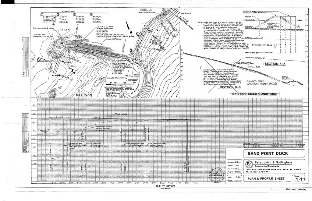
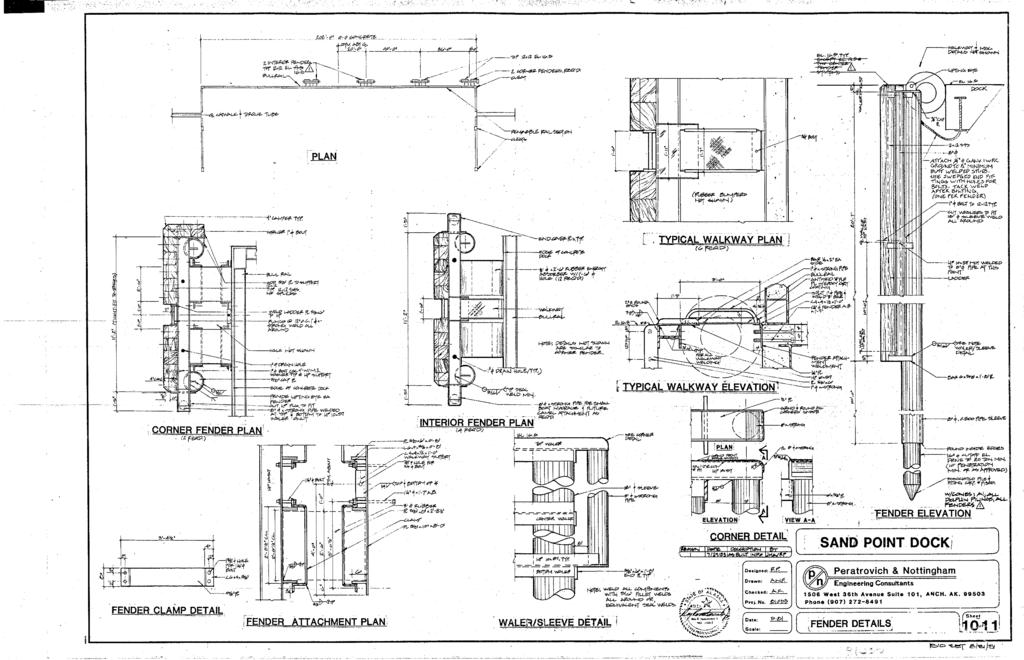
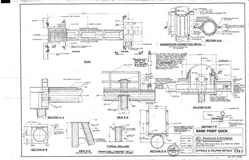
32 PND Engineers, Inc. Sand Point City Dock Replacement Alternatives Analysis Report Appendix D. Existing City Dock Drawings
33
34
35
36
37
38
39
40
41
42
43
44
Ironton Russell Bridge Project
 Construction Update March 1, 2014 Rendering by URS Responsible for Construction Inspection & Engineering Prepared by: Brian Davidson, P.E. Ironton Russell Bridge Project Project Summary: March 1, 2014
Item Name Description Unit of Measure Mobilization Per WSDOT Lump Sum
 Page 1 of 6 DESIGN STANDARDS FOR: MEASUREMENT AND PAYMENT Where bids are utilities for construction, repair or alteration for Public Work park projects, the following bid item descriptions and units of
Ironton Russell Bridge Project
 Construction Update January 1, 2015 Rendering by URS Responsible for Construction Inspection & Engineering Prepared by: Brian Davidson, P.E. Project Overview The Ironton Russell Bridge Project entails
Alternative No. 1 Total Cost DRAFT
 OPINION OF PROBABLE PROJECT COSTS SUMMARY OF ALL THREE ALTERNATIVE ALIGNMENTS Item Description Alternative No. 1 Total Cost Alternative No. 2 Total Cost Alternative No. 3 Total Cost Design Phase 1. Preliminary
Ironton Russell Bridge Project
 Construction Update October 1, 2013 Rendering by URS Responsible for Construction Inspection & Engineering Prepared by: Brian Davidson, P.E. Project Overview The Ironton Russell Bridge Project entails
Ironton Russell Bridge Project
 Construction Update October 1, 2014 Rendering by URS Responsible for Construction Inspection & Engineering Prepared by: Brian Davidson, P.E. Ironton Russell Bridge Project Project Summary: October 1, 2014
WAIKOLOA RESERVOIR NO. 1 EARTHQUAKE REPAIR PROJECT Information Sheet
 March 5, 2015 WAIKOLOA RESERVOIR NO. 1 EARTHQUAKE REPAIR PROJECT Information Sheet Overview The purpose of this Project is to repair damages to the Waikoloa Reservoir No. 1 which were sustained during
Bridge Manual - Part I - June CHAPTER 5 SPECIAL PROVISIONS AND ESTIMATE
 Bridge Manual - Part I - June 2007 5-1 CHAPTER 5 SPECIAL PROVISIONS AND ESTIMATE 5.1 GENERAL This chapter is intended to instruct the Designer in the preparation and submission of Special Provisions and
Bonner Bridge Replacement Update:
 Bonner Bridge Replacement Update: Jerry D. Jennings, PE - NCDOT Division 1 Engineer Pablo A. Hernandez, - NCDOT Resident Engineer September 18, 2017 Bonner Bridge Replacement Timeline Refresher Bonner
Summary Report - Terminal 2 (T2) Trade-Off Process and Outputs Container Capacity Improvement Program
 Trade-Off Process and Outputs Container Capacity Improvement Program") Summary Report - Terminal 2 (T2) Trade-Off Process and Outputs Container Capacity Improvement Program February 2012 Executive Summary Overview This summary report documents concept design and planning
Summary Report - Terminal 2 (T2) Trade-Off Process and Outputs Container Capacity Improvement Program February 2012 Executive Summary Overview This summary report documents concept design and planning
Anchor bolts ASTM F1554, Gr. 36 Wide flange beams ASTM A992, Fy = 50 ksi Misc. structural steel ASTM A36, Fy = 36 ksi
 STRUCTURAL NOTES MATERIAL STRENGTHS Structural Steel Reinforcing Steel Concrete Masonry Structural Lumber Anchor bolts ASTM F1554, Gr. 36 Wide flange beams ASTM A992, Fy = 50 ksi Misc. structural steel
RESEARCH PROJECT AT UNIVERSITY OF NEVADA, RENO
 RESEARCH PROJECT AT UNIVERSITY OF NEVADA, RENO QUARTERLY REPORT October 1, 2016 to December 31, 2016 Period Year 2 Project Shake Table Studies of a Bridge System with ABC Connections Submitted by M. Saiidi,
ENGINEERING DIRECTIVE
 Number: E-95-001 Date: 2/2/95 ENGINEERING DIRECTIVE Ross B. Dindio (Signature on Original) CHIEF ENGINEER The purpose of this engineering directive is to formally notify ALL Department engineering personnel
Table of Contents for Guide Specifications
 Table of Contents for Guide Specifications 01270A Measurement and Payment 01355A Environmental Protection 01356A Storm Water Pollution Prevention Measures 01421 Basic Storm Water Pollution Prevention Plan
Structural Tests and Special Inspections Form. Inspection of Fabricators (1704.2)
") Inspection of Fabricators (1704.2) Furnish inspection reports (1704.2.1) - Fabricators that have not been approved Provide a Certificate of Compliance (1704.2.2) - Approved Fabricators Steel Construction
Inspection of Fabricators (1704.2) Furnish inspection reports (1704.2.1) - Fabricators that have not been approved Provide a Certificate of Compliance (1704.2.2) - Approved Fabricators Steel Construction
TECHNICAL SPECIAL PROVISION FOR CONCRETE REPAIRS. Financial Project ID , &
 TECHNICAL SPECIAL PROVISION FOR CONCRETE REPAIRS Financial Project ID 429140-1-52-01, 429140-2-52-01 & 428267-1-52-01 The official record of this Technical Special Provision is the electronic file signed
Seismic Analysis and Design of Berth 14 Extension Balboa, Panama. Way, WA ; PH (206) ;
 ;") Seismic Analysis and Design of Berth 14 Extension Balboa, Panama J. Paul Smith-Pardo, Ph.D. PE 1 and Christopher B. Cornell, MASCE, PE, SE 2 1 Senior Engineer, BergerABAM, 33301 Ninth Avenue South, Suite
Seismic Analysis and Design of Berth 14 Extension Balboa, Panama J. Paul Smith-Pardo, Ph.D. PE 1 and Christopher B. Cornell, MASCE, PE, SE 2 1 Senior Engineer, BergerABAM, 33301 Ninth Avenue South, Suite
SECTION 820 PUMP STATION DEMOLITION AND SITE RESTORATION
 820-1 SCOPE OF WORK: SECTION 820 PUMP STATION DEMOLITION AND SITE RESTORATION a. Furnish all labor, materials, equipment, and incidentals required for demolition and/or removal and disposal of existing
STATE UNIVERSITY CONSTRUCTION FUND. UNIVERSITY CON DIRECTIVE 5-1 Issue date: October 2014
 STATE STRUCTION FUND DIRECTIVE 5-1 Issue date: October 2014 STRUCTURAL STEEL 1. General: It is the Fund's policy that the design of the structural steel is the prime responsibility of the project's Structural
Project Address: Name of Person Completing Form:
 Statement of Inspections This form is provided as a way to list aspects of the project that require special inspection and testing in accordance with IBC Sections 107.1, 1704, and 1705 and define duties
Attachment D-1: Civil/Structural Scope of Work
 Attachment D-1: Civil/Structural Scope of Work Project: Location: Targa Sound Renewable Fuels Project Tacoma, WA Prepared by: NORWEST ENGINEERING Consulting Engineers 4110 N.E. 122 nd Avenue, Portland,
OPEN CELL. (800) SWC 120. SWC Weld-on. Charts and Pictures courtesy of: 120 o
 SWC 120. SWC Weld-on. Charts and Pictures courtesy of: 120 o") OPEN CELL The OPEN CELL bulkhead, used primarily on docks and similar structures, is a cellular flat sheet pile structure in which each cell s sheet piles are driven in the shape of a U when viewed from
OPEN CELL The OPEN CELL bulkhead, used primarily on docks and similar structures, is a cellular flat sheet pile structure in which each cell s sheet piles are driven in the shape of a U when viewed from
BERTHS 57, 58 AND 59 CONTAINER WHARF AT THE PORT OF OAKLAND
 BERTHS 57, 58 AND 59 CONTAINER WHARF AT THE PORT OF OAKLAND Simo Hoite, PE Associate, Liftech Consultants Inc. Thomas Dahlgren, PE Ben C. Gerwick, Inc. George Fotinos, SE Consultant Reprinted from Ports
Bijan Khaleghi, Ph, D. P.E., S.E.
 0 Submission date: July, 0 Word count: 0 Author Name: Bijan Khaleghi Affiliations: Washington State D.O.T. Address: Linderson Way SW, Tumwater WA 0 INTEGRAL BENT CAP FOR CONTINUOUS PRECAST PRESTRESSED
SECTION ELEVATED BLEACHERS (Angle Frame Semi-Closed Deck)
") SECTION 13125 ELEVATED BLEACHERS (Angle Frame Semi-Closed Deck) PART 1 GENERAL 1.1 RELATED DOCUMENTS A. Drawings and general provisions of the Contract, including General and Supplementary Conditions and
SECTION 13125 ELEVATED BLEACHERS (Angle Frame Semi-Closed Deck) PART 1 GENERAL 1.1 RELATED DOCUMENTS A. Drawings and general provisions of the Contract, including General and Supplementary Conditions and
151 First Side. Technical Assignment 2 November 16 th, William J. Buchko. AE 481w Senior Thesis The Pennsylvania State University
 November 16 th, 2007 William J. Buchko AE 481w Senior Thesis The Pennsylvania State University Thesis Advisor: Kevin Parfitt Table of Contents Executive Summary... 3 Structural System Overview Foundation...
PAUL ZICK, PE NORTH SHORE CONSTRUCTORS JV
 NORTH SHORE CONNECTOR TUNNELS AND STATION SHELL LIGHT RAIL PROJECT PAUL ZICK, PE NORTH SHORE CONSTRUCTORS JV North Shore Connector Alignment 7300 lf Extension to existing 25 mile system 18 Contracts $435
Design and Construction of the SH58 Ramp A Flyover Bridge over IH70. Gregg A. Reese, PE, CE, Summit Engineering Group, Inc.
 Design and Construction of the SH58 Ramp A Flyover Bridge over IH70 Gregg A. Reese, PE, CE, Summit Engineering Group, Inc., Littleton, CO ABSTRACT: The SH58 Ramp A bridge in Golden, CO is the latest on
A. The extent of extruded aluminum walkway covers is shown on the Drawings and as specified herein.
 SECTION 10530 - EXTRUDED ALUMINUM WALKWAY COVERS PART I - GENERAL.1 RELATED DOCUMENTS A. Drawings and general provisions of Contract, including General, Supplementary, and Special Conditions and Division
Implementation of this Special Provision requires a complete understanding of the following documents:
 VIRGINIA DEPARTMENT OF TRANSPORTATION SPECIAL PROVISION FOR Quality Assurance/Quality Control (QA/QC) for the Construction of Deep Foundation Systems for Design-Build and PPTA Contracts November 10, 2009
Open Trench Construction Plan Review The open trench construction plan review involves the following general investigative elements:
 TNC Fisher Slough Final Design and Permitting Subject: Inverted Siphon Construction Feasibility To: From: Jenny Baker (TNC) Dave Olson (DD3) Brian Olson (DD17) Bob Boudinot Skagit County David Cline (Tetra
Highway Cost Index Estimator Tool Final report PRC 17-73
 Highway Cost Index Estimator Tool Final report PRC 17-73 Highway Cost Index Estimator Tool Texas A&M Transportation Institute PRC 17-73 March 2018 Authors Brett Huntsman Brianne Glover, J.D. Samir Huseynov
Retrofit of an Existing Californian Hospital to Immediate Occupancy Standards One Year Later Again R. Jay Love, S.E.
 Retrofit of an Existing Californian Hospital to Immediate Occupancy Standards One Year Later Again R. Jay Love, S.E. Degenkolb Engineers MCEER 2006 Annual Meeting Diagnostic & Treatment Building Designed
Introduction Introduction
 Introduction Maritime International is a leading manufacturer of marine bollards and cleats worldwide. Our range of bollards and cleats is unsurpassed by any other manufacturer or supplier. Maritime can
Redi Rock Specification and Installation Manual
 Redi Rock Specification and Installation Manual 1.0 General Scope This Specification covers the Design, Materials and Installation of Redi Rock modular block Retaining and Freestanding Wall systems as
The Northern Waterfront Seawall History and Earthquake Performance Waterfront Plan Working Group Meeting April 13, 2016
 The Northern Waterfront Seawall History and Earthquake Performance Waterfront Plan Working Group Meeting April 13, 2016 Steven Reel, PE - Project Manager, Engineering Division, Port 1 The Northern Waterfront
Continuous for Live Load: A Texas Historical Perspective
 Continuous for Live Load: A Texas Historical Perspective Scott Walton, M.S.C.E., E.I.T. 1, and Timothy E. Bradberry, M.S.E., P.E. 2 Abstract A significant number of engineers in the United States have
PUBLIC WORKS SKAGIT COUNTY SAMISH ISLAND ROAD SAMISH ISLAND ROAD SLIDE REPAIR
 EASEMENT NOTES:. EASEMENT LIMIT SHOWN AS PROVIDED BY. TESC NOTES:. CONTRACTOR SHALL DEVELOP TEMPORARY EROSION AND SEDIMENT CONTROL PLAN AND PROVIDE ONSITE CERTIFIED EROSION AND SEDIMENT CONTROL LEAD (CESCL)
THE RION ANTIRION BRIDGE DESIGN AND CONSTRUCTION
 THE RION ANTIRION BRIDGE DESIGN AND CONSTRUCTION Jean-Paul TEYSSANDIER 1, Jacques COMBAULT 2 And Pierre MORAND 3 SUMMARY The RION-ANTIRION Bridge (Greece) is located in a zone of difficult environmental
CIVIL BREADTH Exam Specifications
 NCEES Principles and Practice of Engineering Examination CIVIL BREADTH and STRUCTURAL DEPTH Exam Specifications Effective Beginning with the April 2015 Examinations The civil exam is a breadth and depth
The designer shall also submit additional information required by the University as described and underlined below.
 I. Structural Engineering Submissions The designer shall submit all information required by the State Construction Office (SCO) as described in the State Construction Manual Chapter 300 - Project Design
KIEWIT LEDCOR TMEP PARTNERSHIP 2115 Commissioner Street Site 1 - PER Application, Category C. August 17, Vancouver Fraser Port Authority
 August 17, 2017 Vancouver Fraser Port Authority 100 The Pointe, 999 Canada Place Vancouver, BC, Canada V6C 3T4 Attention: Jessica Mehigan Subject: Overview Kiewit Ledcor TMEP Partnership ( KLTP ) has been
16. Design of Pipeline Structures.
 16. Design of Pipeline Structures. a. General. 1) The following guidelines are for the design of structures for water and sewer pipelines including structural concrete and miscellaneous metals design.
LANDSCAPE RETAINING WALLS
 SUDAS Standard Specifications Division 9 - Site Work and Landscaping Section 9070 - Landscape Retaining Walls LANDSCAPE RETAINING WALLS PART - GENERAL.0 SECTION INCLUDES A. Modular Block Retaining Walls
SECTION DUCTILE IRON PILES
 SECTION 31 66 13 DUCTILE IRON PILES PART 1 - GENERAL 1.1 GENERAL REQUIREMENTS A. Work of this Section, as shown or specified, shall be in accordance with the requirements of the Contract Documents. B.
Structural Design of Dam Sluice Gate Walkway Slabs: Retrofit and Replacement Options
 Structural Design of Dam Sluice Gate Walkway Slabs: Retrofit and Replacement Options A local utility company issued a Request for Proposal to our university s capstone design class for structural improvements
SPECIFICATIONS FOR PRECAST MODULAR BLOCK RETAINING WALL SYSTEM (revised 5/8/7)
") Page 1 of 7 STONE STRONG SYSTEMS SPECIFICATIONS FOR PRECAST MODULAR BLOCK RETAINING WALL SYSTEM (revised 5/8/7) PART 1: GENERAL 1.01 Description A. Work includes furnishing and installing precast modular
Page 1 of 7 STONE STRONG SYSTEMS SPECIFICATIONS FOR PRECAST MODULAR BLOCK RETAINING WALL SYSTEM (revised 5/8/7) PART 1: GENERAL 1.01 Description A. Work includes furnishing and installing precast modular
Bethel Bank Stabilization
 Bethel Bank Stabilization Condition of Improvements 30 December 2014 Bethel Bank Stabilization, Alaska (CWIS No. 012314, 075440) Authorization Public Law 99-662, under Section 202, 17 November 1986, as
1. Cast-in-place concrete is specified in Section
 SECTION 03 38 00 PART 1 - GENERAL 1.01 DESCRIPTION A. This Section describes the requirements for furnishing and installing post-tensioned slabs, jacks, jacking and anchors at Parking Structure, and record
CONSTRUCTION PROCEDURES. AWWA D110 Type I Prestressed Concrete Tanks
 CONSTRUCTION PROCEDURES AWWA D110 Type I Prestressed Concrete Tanks 2-3 4-5 6-7 8-9 10-11 12-13 14-15 16-17 Site Preparation Floor & Footings Wall Construction Roof Options Vertical Prestressing Abrasive
Society of Women Engineers Region H Conference
 Society of Women Engineers Region H Conference Faith Duncan, PE & Greg Hasbrouck, PE Replacing the Aging US 52 Mississippi River Bridge February 27, 2016 Project Overview US 52 / IL 64 over the Mississippi
DIVISION 31 EARTHWORK 2006 Edition, Published January 1, 2006; Division Revision Date: January 31, 2012
 2006 Edition, Published January 1, 2006; Division Revision Date: January 31, 2012 PART FIVE DOCUMENTS FOR SITE AND INFRASTRUCTURE 31 00 00. EARTHWORK 31 10 00. SITE CLEARING.1 STRUCTURE REMOVAL: Include
Table of Contents.2. Introduction...3 Gravity Loading and Deflections..4. Existing Structural System..8
 WISCONSIN PLACE RESIDENTIAL TECHNICAL ASSIGNMENT 2 OCTOBER 29, 2007 KURT KRASAVAGE THE PENNSYLVANIA STATE UNIVERSITY STRUCTURAL OPTION FACULTY ADVISOR: DR. ALI MEMARI 1 Table of Contents Table of Contents.2
Capital Rail Constructors: Quarterly Update to MWAA Board of Directors
 Dulles Corridor Metrorail Project Phase 2, Package A Capital Rail Constructors: Quarterly Update to MWAA Board of Directors Keith Couch Capital Rail Constructors January 2018 Agenda 1. Safety 2. Schedule
RFP/GRC/LSV/ : RENOVATION (CIVIL WORKS) AT SKALA SYKAMNIAS CHILDRENS PLAYGROUND BILL OF QUANTITIES
 AT SKALA SYKAMNIAS CHILDRENS PLAYGROUND BILL OF QUANTITIES") RFP/GRC/LSV/2017-003: RENOVATION (CIVIL WORKS) AT SKALA SYKAMNIAS CHILDRENS PLAYGROUND BILL OF QUANTITIES 1/7 The Contractor shall consider in his price all costs or expenses of all requirements stipulated
RFP/GRC/LSV/2017-003: RENOVATION (CIVIL WORKS) AT SKALA SYKAMNIAS CHILDRENS PLAYGROUND BILL OF QUANTITIES 1/7 The Contractor shall consider in his price all costs or expenses of all requirements stipulated
BILL OF QUANTITIES. Construction and Rehabilitation of wadi Gaza Bridges PAL Funded by Government of Brazil
 United Nations Development Programme Programme of Assistance to the Palestinian People-PAPP Construction and Rehabilitation of wadi Gaza Bridges PAL10-00054031 Funded by Government of Brazil BILL OF QUANTITIES
SPECIFICATION SECTION 05515: LADDERS O Keeffe s Aluminum Ladders
 Welcome to the O Keeffe s Guide Specification System prepared as an aid to specify in preparing written construction documents. For specification assistance with specific product applications, please contact
MARINE SPECIALTY CONTRACTORS GENERAL TRADE KNOWLEDGE EXAMINATION CONTENT INFORMATION FOR COMPUTER BASED TESTING Revised March 2012
 MARINE SPECIALTY CONTRACTORS GENERAL TRADE KNOWLEDGE EXAMINATION CONTENT INFORMATION FOR COMPUTER BASED TESTING Revised March 2012 The General Trade Knowledge examination will be administered in one session
DIVISION 03 CONCRETE SPECIFICATION : FORMS AND FORMWORK
 DIVISION 03 CONCRETE SPECIFICATION 031000: FORMS AND FORMWORK PART 1.0 GENERAL 1.1 DESCRIPTION The work of this specification includes furnishing of all labor, materials, equipment and incidentals to install,
Appendix D - Evaluation of Interim Solutions
 Appendix D - Evaluation of Interim Solutions D.1 Introduction The implementation of long-term improvements is projected to take 5 to 8 years. To reduce the number of years of flooding impacts, the partner
MATERIAL ALLOWANCES AND UNIT PRICES
 PART 1 - GENERAL 1.1 SECTION INCLUDES ADDITIONS AND RENOVATIONS TO WEST YORK AREA HIGH SCHOOL - #1231 SECTION 012200 MATERIAL ALLOWANCES AND UNIT PRICES A. Measurement and payment criteria applicable to
JULY 2016 LRFD BRIDGE DESIGN 11-1
 JULY 016 LRFD BRIDGE DESIGN 11-1 11. ABUTMENTS, PIERS, AND WALLS This section contains guidance for the design and detailing of abutments, piers, retaining walls, and noise walls. Abutments and piers are
PROGRAMMATIC ENDANGERED SPECIES ACT CONSULTATION Piling Replacement List of Requirements Version: May 3, 2017
 PROGRAMMATIC ENDANGERED SPECIES ACT CONSULTATION Piling Replacement List of Requirements Version: May 3, 2017 Programmatic Endangered Species Act (ESA) Consultations [U.S. Fish and Wildlife Service (USFWS)
Tolerances for Concrete Construction. Tolerances for Concrete Construction. Tolerance 6/16/2015
 Tolerances for Concrete Construction Thomas J Downs P.E., FACI President Forensic Experts Minneapolis, MN What is it? Tolerances for Concrete Construction When did we start this anyway? Who said we needed
BILL SUMMARY. March 15, 2018 BILL No. DESCRIPTION AMOUNT
 PROJECT: CONSTRUCTION OF NEW TIMBER WHARF, SOUTHERN BILL No. DESCRIPTION AMOUNT 1 PRELIMINARIES 2 DEMOLISHION WORKS 3 TIMBER WHARF CONSTRUCTION 4 CATWALK CONSTRUCTION BILL SUMMARY 5 CONCRETE WALKWAY CONSTRUCTION
CONCRETE SPLICED GIRDERS IN TEXAS. Nicholas Nemec, P.E. TxDOT-BRG
 CONCRETE SPLICED GIRDERS IN TEXAS Nicholas Nemec, P.E. TxDOT-BRG October 15, 2014 What is a Concrete Spliced Girder? 2 What is a Concrete Spliced Girder? What it is NOT : Continuous For Live Load 3 What
***************************************************************************************************************
 02720 STORM DRAINAGE SYSTEM *************************************************************************************************************** SPECIFIER: CSI MasterFormat 2004 number 33 40 00. ***************************************************************************************************************
North Mountain IMS Medical Office Building
 North Mountain IMS Medical Office Building Phoenix, Arizona Michael Hopple Technical Assignment 2 October 29 th, 2007 AE 481W-Senior Thesis The Pennsylvania State University Faculty Adviser: Dr. Ali Memari,
ESTIMATE OF QUANTITIES
 ESTIMATE QUANTITIES STATE S.D. SHEET NO. TOTAL SHEETS 2 12 SPECIFICATIONS TEMPORARY PAVEMENT MARKING, Continued STATE S.D. SHEET NO. TOTAL SHEETS 3 12 South Dakota Standard Specifications for Roads and
Immersed Tunnels. Richard Lunniss and Jonathan Baber. CRC Press. Taylor & Francis Group. Taylor & Francis Group, A SPON BOOK
 Immersed Tunnels Richard Lunniss and Jonathan Baber CRC Press Taylor & Francis Group Boca Raton London New York CRC Press is an imprint of the Taylor & Francis Group, an informa business A SPON BOOK Contents
PREFABRICATED STEEL TRUSS SPECIFICATIONS
 PREFABRICATED STEEL TRUSS SPECIFICATIONS 1. GENERAL 1.1 Scope All engineering design and related detailing of the bridge(s) shall be provided by the supplier. The design and detailing shall conform to
SLAB ON GRADE Insul-Joint or Expansion Joint Material as Required by A/E Specifications AquaCheck Liquid Coating 400 (Waterproofing Membrane) with Aqu
 with Aqu") INSTALLATION INSTRUCTIONS Note: The following installation instructions are based off of ASTM E 1643 (Standard Practice for Installation of Water Vapor Retarders Used in Contact with Earth or Granular
INSTALLATION INSTRUCTIONS Note: The following installation instructions are based off of ASTM E 1643 (Standard Practice for Installation of Water Vapor Retarders Used in Contact with Earth or Granular
SECTION A1 EXCAVATION AND BACKFILL GENERAL
 SECTION A1 EXCAVATION AND BACKFILL GENERAL The work under this section shall include all excavation to such width and depth as shown on the drawings, specified herein, or ordered by the Engineer. Such
The Hashemite University Department of Civil Engineering. Dr. Hazim Dwairi. Dr. Hazim Dwairi 1
 Department of Civil Engineering Lecture 2.1 Methods of Prestressing Advantages of Prestressing Section remains uncracked under service loads Reduction of steel corrosion (increase durability) Full section
1 Exam Prep Placing Reinforcing Bars Tabs and Highlights
 1 Exam Prep Placing Reinforcing Bars Tabs and s These 1 Exam Prep Tabs are based on the CRSI Placing Reinforcing Bars Recommended Practices, 9 th Edition. Each 1 Exam Prep tabs sheet has five rows of tabs.
Lesner Bridge Replacement
 Lesner Bridge Replacement Rendering of the Completed Lesner Bridge Structure Construction Camera A Construction Camera has been installed to view images of the bridge construction. Images are updated on
CHAIN LINK FENCES AND GATES
 SECTION 02831 CHAIN LINK FENCES AND GATES PART 1 GENERAL 1.01 SUMMARY A. Alternate Material for Fence Post and Framing Material: Where schedule 40 galvanized steel is specified, the following will be accepted:
REQUEST FOR PROPOSAL Asphalt & Concrete Repair
 REQUEST FOR PROPOSAL 2017 Asphalt & Concrete Repair English Landing Elementary School Union Chapel Elementary School Lakeview Middle School Park Hill High School Prairie Point Elementary School Congress
STANDARD SPECIFICATIONS SECTION TUNNELING. A. Section includes requirements for constructing tunnels 48-inch and larger diameter.
 STANDARD SPECIFICATIONS SECTION 02420 TUNNELING PART 1 GENERAL 1.1 DESCRIPTION A. Section includes requirements for constructing tunnels 48-inch and larger diameter. 1.2 DEFINITIONS A. Carrier Pipe: Sewer
Short Span Steel Bridges
 Short Span Steel Bridges MINK 2015 Michael Barker, PE University of Wyoming & SSSBA Bridge Technology Center Outline of Today s Presentation SSSBA & espan140 Design Competitiveness of Steel Bridges Economics
Section 906. STRUCTURAL STEEL
 906.01 Section 906. STRUCTURAL STEEL 906.01. General Requirements. Finished rolled shapes must be free from imperfections that affect strength and durability in accordance with ASTM A 6. Rolled shapes
TOWN OF MOUNT PLEASANT WESTCHESTER COUNTY, NEW YORK
 TOWN OF MOUNT PLEASANT WESTCHESTER COUNTY, NEW YORK COST EVALUATION FOR ROLLING HILLS AREA WATER MAIN EXTENSION PROFESSIONAL CONSULTING, LLC. Octagon 10, Office Center 1719 Route 10, Suite 225 Parsippany,
NORFOLK SOUTHERN CORPORATION UNDERPASS GRADE SEPARATION DESIGN CRITERIA
 NORFOLK SOUTHERN CORPORATION UNDERPASS GRADE SEPARATION DESIGN CRITERIA PURPOSE AND SCOPE These criteria modify and supplement the applicable sections of the AREMA Manual of Recommended Practice in connection
***************************************************************************************************************
 03365 POST-TENSIONED CONCRETE *************************************************************************************************************** SPECIFIER: CSI MasterFormat 2004 number 03 38 00. ***************************************************************************************************************
Performance of Mechanically Stabilized Earth walls over compressible soils
 Performance of Mechanically Stabilized Earth walls over compressible soils R.A. Bloomfield, A.F. Soliman and A. Abraham The Reinforced Earth Company, Vienna, Virginia, USA ABSTRACT: Two projects have recently
Jobsite Layout Considerations
 1 Jobsite Layout Considerations The controlling contractor must consider many factors when laying out a site to support construction operations Site and building size and Equipment requirements configuration
Brent Ellmann Structural Option 200 Minuteman Park, Andover, MA Structural Consultant: Dr. Hanagan
 Executive Summary: 200 Minuteman Park currently stands as a three story commercial building. The original design was limited to three stories by an industrial zoning law in Andover, Massachusetts. If this
PIANC UK Seminar Design Developments and Specification for Steel. Duncan Nicholson Arup Fellow 9/3/17 ICE London
 PIANC UK Seminar Design Developments and Specification for Steel Duncan Nicholson Arup Fellow 9/3/17 ICE London Contents 1. Design Issues 2. SPERWall Edition 3 (2016) 1. Steel Sheet Piles (Section 14)
Jacksonville Port Authority Blount Island Marine Terminal Rail Improvements Jacksonville, Florida
 Jacksonville Port Authority Blount Island Marine Terminal Rail Improvements Jacksonville, Florida By: Bryan K. Haye, Senior Project Manager; Michael J. Shostak, P.E., Vice President; and Clinton C. Lalla,
RAILING DESIGN FOR NEW TRUSS BRIDGES. Texas Transportation Institute The Texas A&M University System College Station, Texas
 1. Report No. FHWA/TX-05/0-4419-4 4. Title and Subtitle RAILING DESIGN FOR NEW TRUSS BRIDGES 2. Government Accession No. 3. Recipient's Catalog No. Technical Report Documentation Page 5. Report Date October
SECTION CAST-IN-PLACE CONCRETE
 SECTION 03300 CAST-IN-PLACE CONCRETE PART 1 GENERAL 1.01 SECTION INCLUDES A. The Contractor shall furnish all work and materials, including cement, sand and coarse aggregate, water, admixtures, curing
A. Pre-engineered, pre-finished extruded aluminum Pavilions.
 10 73 00 SECTION Pavilions PART 1 GENERAL 1.1 SECTION INCLUDES A. Pre-engineered, pre-finished extruded aluminum Pavilions. 1.2 RELATED SECTIONS A. Section 03100 - Concrete Forms and Accessories. B. Section
SECTION STRUCTURAL PRECAST HOLLOW CORE SLABS
 PART 1 GENERAL 1.01 SCOPE OF WORK A. The Contractor shall furnish all labor, materials, equipment and incidentals to provide a complete structural precast hollow core slab system as shown on the Contract
LRFD SEISMIC BRIDGE DESIGN, CALIFORNIA EXAMPLE. Mark S. Mahan 1
 LRFD SEISMIC BRIDGE DESIGN, CALIFORNIA EXAMPLE Mark S. Mahan 1 Abstract The newly approved AASHTO Guide Specification for LRFD Seismic Bridge Design (referred to as LRFD Seismic Guide Spec), July 2007,
BILL OF QUANTITY ENGINEERING & MANAGEMENT CONSULTING CENTRE. "Beit Hanoun Emergency Water Supply Project"
 "Beit Hanoun Emergency Water Supply Project" " Rehabilitation and Construction of Beit Hanoun Water Network " BILL OF QUANTITY ENGINEERING & MANAGEMENT CONSULTING CENTRE Bill of Quantities PREAMBLE TO
SECTION FACILITY SANITARY SEWERS
 SECTION 22 13 13 FACILITY SANITARY SEWERS PART 1 - GENERAL 1.1 RELATED DOCUMENTS A. Drawings and general provisions of the Contract, including General and Supplementary Conditions and Division 01 Specification
JULY 2014 LRFD BRIDGE DESIGN 5-1
 JULY 014 LRFD BRIDGE DESIGN 5-1 5. CONCRETE STRUCTURES Reinforced and prestressed concrete are used extensively in bridge projects. In addition to general design guidance and information on detailing practices,
SECTION PLATE CONNECTED WOOD TRUSSES
 SECTION 06173 PLATE CONNECTED WOOD TRUSSES PART 1 GENERAL 1.01 SUMMARY A. Section Includes: 1. Shop fabricated wood trusses for roof and floor framing. 2. Bridging, bracing, and anchorage. B. Related Sections:
INDEX FOR SPECIFICATIONS FOR JACKING CULVERTS THROUGH EMBANKMENTS SCOPE... 2
 INDEX FOR SPECIFICATIONS FOR JACKING CULVERTS THROUGH EMBANKMENTS 410. 1 SCOPE... 2 410. 2 DEFINITIONS 2.1 Tunneling and Jacking... 2 2.2 Tunneling... 2 2.3 Jacking... 2 410. 3 MATERIALS 3.1 General...
SECTION VIBRATION AND SEISMIC CONTROLS FOR ELECTRICAL SYSTEMS
 PART 1 - GENERAL 1.1 RELATED DOCUMENTS A. Drawings and general provisions of the Contract, including General and Supplementary Conditions, apply to this Section. 1.2 SUMMARY A. This Section includes the