Installation Guide Roofing. Sarnafil Membranes
|
|
|
- Stephen Collins
- 6 years ago
- Views:
Transcription
1 Roofing
2 1.1 Introduction 1.2 General Information The Sarnafil G/S roofing system The Sarnafil TCG/TCS roofing system Procedures on site Compatibility Cleaning / Seam preparation Hand welding Automatic welding Trial welding Seam check during welding Seam check after welding Welds at transverse joints Adhered Flashings Perimeter Fastening Flashings & Perimeters Base of upstand flashings (System Optimisation # 3) Fixing of Sarnametal Trims Welding directly to 1.3 Sarnametal trims (System Optimisation # 1) Sealing along parapets and upstands Sealing Pipes and Penetrations 1.3 Vapour Control Layers 1.4 System Constructions Sarnafil G/TCG, loose laid system Sarnafil S/TCS, Sarnabar System Sarnafil S/TCS, Sarnafast System (including System Optimisation # 2) Sarnafil G, Adhered system 2
3 1.5 Procedures Inside Corner with Horizontal Crease Inside Corner with Vertical Crease Outside Corner Upstands at Curved Parapets Sarnafil T Prefabricated Corners Inside Corner with Prefabricated sections Outside Corner with Prefabricated sections 1.6 Standard Details Sarnametal roof trims SikaBond Adhesives Lightning Protection Perimeters with Gravel Stops Rooflight Sarnafil Rainwater Outlets Scuppers, overflows and shute outlets Pipes/Penetrations Constant Force Post Sarnafil Liquid Detailing System 1.7 Aesthetic Profiles Decor Profile Batten Profile 1.8 Special Details Movement joint Connection to bituminous roofing 1.9 Safety/Control Day joints Partitioning on bituminous vapour control layers Flood Testing 3
4 1.1 Introduction Sika Sarnafil has more than 50 years experience in waterproofing plastics technology. Today Sika Limited is a world leader in waterproofing, but even our products are only as good as the workmanship with which they are installed. That is why we place great emphasis on training people to install Sarnafil and offer a wide range of courses. Only site operatives who have successfully completed one of our Sarnafil training courses and have regular, practical site experience may install Sarnafil systems. This section is intended to supplement the knowledge acquired during the Sarnafil training course and to serve as an on-site reference. 1.2 General Information The Sarnafil G/S roofing system Products to be used for the Sarnafil G/S roofing systems are labelled accordingly. They may only be used for this system. Sarnafil G is a synthetic Polyvinylchloride (PVC) waterproof sheeting suitable for loose laid or adhered applications. Sarnafil G is manufactured using a glass fibre carrier which is not subject to shrinkage and is therefore dimensionally stable. Sarnafil S is a synthetic Polyvinylchloride (PVC) waterproof sheeting suitable for mechanical fastening. Sarnafil S is reinforced with a polyester scrim which gives it a high tear resistance and the relatively low elongation-at-break factor required for this application The Sarnafil TCG/TCS roofing system Sarnafil TC, a plastic alloy of flexible polyolefines (FPO), is based on 4 decades of experience in synthetic membranes. It is manufactured to the highest standard by extrusion coating on our own specially developed production plant. Sarnafil TC represents state-of-the-art synthetics technology and meets the most stringent ecological requirements. The accessories developed for the Sarnafil FPO roofing systems must be used with the TCG/TCS systems. Sarnafil TCG is a synthetic waterproof sheeting suitable for loose laid applications. Sarnafil TCG is manufactured using a glass fibre carrier which is not subject to shrinkage and is therefore dimensionally stable. Sarnafil TCS is a synthetic waterproof sheeting suitable for mechanical fastened applications. Sarnafil TCS is a combination of glass fibre matting and synthetic scrim which give it high tear resistance and the relatively low elongation-at-break factor required for this application. 4
5 1.2.3 Procedures on site On the building site Sarnafil membranes must be protected against exposure. When stored under clean, dry conditions Sarnafil membranes can be welded without any additional cleaning or seam preparation. The procedure for installing the Sarnafil roofing must be planned beforehand and adapted to the site and weather conditions: Define daily work stages. Ensure that rain water can drain off at all times. Make sure daily work stages are leak proof (waterproofing of daily stages, seams and perimeters, welding over fasteners and bars) Waterproof sealing should be ensured by systematically following the procedures in the relevant Installation Guide and carrying out the appropriate tests. Welding test to check the tool settings (manual and automatic welding). Checking seams during and after welding. Inspection of roofing system Compatibility Sarnafil membranes are resistant to the environmental affects relevant today including many chemicals. Sarnafil G/S membranes are not however resistant to bitumen, tar, asphalt or oil. When using S membrane or loose laid G a suitable separation layer must be installed over such materials. For polystyrene insulation boards a Sarnafil separation layer is also required. For adhered membrane systems G membrane with an integral polyester fleece (G410-ELF) should be used where separation is required. Sarnafil TC membranes are suitable for installation directly on top of existing, carefully cleaned, level bituminous roofing, e.g. re-roofing over old flat roofs. In the case of partitioning, Sarnafil TCG is adhered directly on to the bituminous vapour barrier. For compatibility of specific materials, always check with Sarnafil Technical Services. 5
6 1.2.5 Cleaning / Seam preparation Sarnafil G/S (PVC) Membranes For Sarnafil G/S to be properly welded, the overlapping area must be clean. Soiled Sarnafil G/S should be cleaned prior to welding. Depending on the type of soiling, the material should be cleaned with water or Sarnafil seam cleaner. Condition of Sarnafil - Dirty Sarnafil G/S (loose drilling dust, building site dirt) - Heavily soiled Sarnafil G/S (repair work, extensions to existing membrane etc.) - Plate-out (caused by storage at high temperatures) Blistering due to moisture (regular diameter blisters) Blistering due to solvent (irregular diameter blisters) Bitumen residue Adhesive residue Step to be taken in overlap area (both surfaces) - Wipe off loose dirt - If necessary, wash down with water - Wipe off loose dirt - Clean with water, aqueous all-purpose cleaner using a brush or cleaning pad if necessary - Remove heavy soiling with Sarnafil Lap Cleaner, allow Sarnafil Lap Cleaner to evaporate completely (blistering) - Treat greasy surface with Sarnafil Lap Cleaner - Select lower temperature for welding - Allow Sarnafil G/S to dry - Weld slowly with as low a temperature as possible - When cleaning with solvent, weld Sarnafil G/S immediately or allow solvent to evaporate completely - When using solvent based adhesives weld immediately or wait approx. 7hrs before welding. - Remove with Sarnafil Lap Cleaner - Remove with Sarnafil Cleaner; before welding allow any areas cleaned with Sarnafil cleaner to evaporate completely (blistering) Notes: When repairing membranes the new Sarnafil G/S sheet should be laid underneath the existing roofing. Caution: Avoid all contact between Sarnafil Cleaner and polystyrene panels. 6
7 Sarnafil TC (FPO) Membranes New clean Sarnafil TC sheets do not generally need to be prepared for welding. However, when welding soiled membrane or when welding to T membrane or accessories, seam preparation will be required (unless using a Sarnamatic fitted with a Prep nozzle). For cleaning and seam preparation a differentiation is made between the site phase (installation phase) and the utilisation phase. If cleaning is required, then a subsequent seam preparation must be carried out. Installation phase (slight soiling) Seams should be prepared with Sarnafil T Prep (yellow). For slight soiling the preparation agent Sarnafil T Prep may be used for both cleaning and the subsequent seam preparation. Utilisation phase (heavy soiling) For heavily soiled material Sarnafil T Clean (reddish colour) must be used. Important: Only soiled surfaces should be cleaned! Treating both sides of the seam overlap with Sarnafil T clean will reduce seam quality. Subsequent seam preparation is carried out using Sarnafil T Prep (yellow). General For seam preparation and until actual welding the seam area must be clean and dry. During cleaning the cloths should be frequently renewed, otherwise dirt will simply be spread over the sheet and not removed! A new cleaning cloth must be used for the seam preparation. White cloths will effectively absorb dirt and the colour will not stain the membrane. Note: Our product range includes suitable seam preparation kits. Where required seam area must be treated on both sides immediately prior to welding. For seam preparation and until actual welding the seam area must be clean and dry. 7
8 Condition of Sarnafil - New & clean Sarnafil TC Step to be taken in overlap area (both surfaces) - None - Dirty Sarnafil TC (loose drilling dust, building site dirt, bitumen residue) - Heavily soiled Sarnafil TC (repair work, extensions to existing membrane etc.) - Sarnafil TG/TS membrane / FPO accessories - Wipe off loose dirt - If necessary, wash down with water - Clean with Sarnafil T Prep - Prepare seam using a clean cloth impregnated with Sarnafil T Prep - Allow T Prep to dry - Wipe off loose dirt - Clean with water, aqueous all-purpose cleaner using a brush or cleaning pad if necessary - Clean with Sarnafil T Clean (only soiled areas) - Allow Sarnafil T Clean to dry (minimum 1 hr evaporation time) - Prepare seam using a clean cloth impregnated with Sarnafil T Prep - Allow T Prep to dry - Wipe off loose dirt - Clean with Sarnafil T Prep - Prepare seam using a clean cloth impregnated with Sarnafil T Prep - Allow T Prep to dry Notes: When repairing membranes the new Sarnafil TC sheet should be laid underneath the existing roofing. Caution: When using cleaning fluids and the seam preparation agent, we recommend that protective gloves be worn. Avoid all contact between Sarnafil T Cleaner and polystyrene insulation boards! 8

 Sarnafil teflon 28mm roller")


9 1.2.6 Hand welding The following tools are available for welding Sarnafil membranes: Hand welding gun 2. 20mm wide welding nozzle 3. 40mm wide welding nozzle 4. Sarnafil silicone 40mm roller (Sarnafil G/S membranes) Sarnafil teflon 28mm roller (Sarnafil TC membranes) For straight welds the 40mm wide nozzle is used. The 20mm wide nozzle is used for detail work. For optimum welding it must be ensured that the complete air outlet section is located within the weld overlap. The air outlet section of the nozzle must be of uniform width and open over the entire width. The nozzle should be positioned so that it forms an airtight seal on to the neck of the hand welding gun. The air intake slots must be open and free of dust. Any accumulated dust or dirt is best removed away from the nozzle with a brush or compressed air. 9


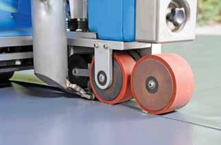
10 General The temperature must be adjusted to suit the selected nozzle width and the particular type of welder. Settings for Sarnafil G/S Hand Welder Leister Nozzle Nozzle 20mm 40mm Triac S/ST Setting 5 Setting 6.5 Triac PID/AT 380 C C 380 C C Note: Higher settings are to be avoided at all costs (poor seam quality will result). Settings for Sarnafil TCG/TCS Hand Welder Leister Nozzle Nozzle 20mm 40mm Triac S/ST Setting 4.5 Setting 5 Triac PID/AT 280 C C 280 C C Note: Higher settings are to be avoided at all costs (poor seam quality will result). Welding procedure When welding Sarnafil membranes the overlap area must be clean and dry. For Sarnafil TC membranes, the overlap areas may require preparation. See Cleaning/Seam Preparation for details. The overlap widths required are as follows - Adhered and Loose laid systems the overlap is 80mm For Sarnabar mechanically fastened systems the overlap is 80mm For Sarnafast mechancically fastened systems the overlap is 120mm Hand welding is carried out in three stages: 1. Spot weld/tack the overlap. 2. Pre-weld: Weld the rear overlap area so that a 35mm opening (when using 40mm nozzle) remains for the finishing weld. 3. Final weld: For this stage the appropriate Sarnafil pressure roller should be guided at a distance of 30mm parallel to the air outlet of the welding nozzle. Always roll the Sarnafil pressure roller fully across the seam. 10
.")
11 1.2.7 Automatic welding Basic Settings for Sarnafil G/S Sarnamatic 641/641mc 220V / 230V Sarnamatic 661 plus Speed 18 Select membrane type Temperature 430 C Select membrane type Air Setting 3 Select membrane type Note: The basic settings must be checked and if necessary adjusted, by observing the welding pattern (for trial weld and seam check see relevant section). Basic Settings for Sarnafil TC Sarnamatic 641/641mc 220V / 230V Sarnamatic 661 plus Speed 30 Select membrane type Temperature 400 C Select membrane type Air Setting 3 Select membrane type Note: The basic settings must be checked and if necessary adjusted, by observing the welding pattern (for trial weld and seam check see relevant section). Sarnamatic 661plus The Sarnamatic 661plus is the latest generation of automatic hot air welders designed specifically for use with Sarnafil membranes of all thicknesses. The Sarnamatic 661plus provides: Easy to read digital display Push button selection of membrane type Temperature display and temperature control Adjustable wheel width enabling the machine to weld on a platform 170mm wide Refer to the Sarnamatic Operating Instructions for further information. Important: Always start and stop Sarnamatics on a Welding Plate. 11


12 1.2.8 Trial welding Additional weight An additional weight is included which provides optimum welding quality for Sarnafil G and Sarnafil S membranes. The additional weight may be required if the material thickness exceeds 1.2 mm. When welding Sarnafil TC membranes the additional weight must be used! The 5kg additional weight provides optimum welding quality for Sarnafil TC even on soft insulation materials (e.g. fibrous insulation boards). The absolutely secure welding of Sarnafil is ensured by: trial welding with peel test prior to the actual welding procedure seam check during welding seam check after welding Before welding the membrane, a trial weld with subsequent peeling test, across and along the seam direction, should be carried out. This trial welding serves to check the basic settings of the automatic welding machine and if necessary, to adjust the machine settings to site conditions. Peeling test across the seam The fully cooled welded seam must not separate during the peeling test. Any tearing must be located outside the welded seam, either in the Sarnafil synthetic sheeting or within the area of the reinforcing material. Peeling test along the seam The fully cooled weld is tested by pulling away the upper sheet at the beginning or at the end of the seam (pulling in the direction of the seam). In this way it can be established whether a continuous welded bond has been achieved across the whole width of the seam. 12


13 1.2.9 Seam check during welding Seam check after welding During welding the seam area should be checked visually for smoke, shiny surface and size of the welding bead. Too high a welding temperature and/or too slow a welding speed cause the following: Brown discoloration next to and in the weld itself - If this occurs the welding temperature must be reduced and/or the welding speed increased. Formation of a welding bead during automatic welding - During automatic welding the welding bead extrusion can be seen underneath the pressure roller during the welding process. For G/S membranes - after the cooling-off period a clearly visible welding bead remains. For TC membranes - after the cooling-off period little or no welding bead will remain. A permanent, large welding bead is an indication of an improperly welded seam. Formation of welding bead during manual welding - During manual welding the welding bead is more prominent and remains clearly visible after cooling. Visual seam check After welding, all welded seams should be inspected for workmanship and water tightness. Special attention should be paid to crossing and transverse joints, penetrations and seams. The seams should be inspected for a shiny surface and the quality of welding beads. Mechanical seam check All seams must be checked mechanically once they have completely cooled. For this purpose a suitable probe should be used and although pressure should be applied to the seam, the sheeting must not be damaged. The mechanical seam check is not a leak test but assists in locating any seam areas not fully welded. Peeling Test If required the welding can be assessed by a peeling test across the seam direction (e.g. as part of the handing over/acceptance of the flat roofing). Flood testing This check offers maximum safety for the proper functioning of the flat roofing and permits qualified acceptance of the flat roofing (see Flood Testing). Vacuum Testing If required the cross joint welding can be checked by vacuum testing. Electronic Integrity Testing If required electronic integrity testing can be carried out by specialist testing companies where this is a specific requirement. 13


14 Welds at transverse joints Cross joints are to be avoided. By proper arrangement of the Sarnafil sheets all seams can be reduced to straight weld seams and transverse joints Adhered Flashings To achieve continuous watertight welding, Sarnafil membranes with thicknesses above 1.5mm must be chamfered in the area of transverse joints. An edge-trimming plane is used to chamfer the front edge of the seam. To achieve continuous watertight welding, ensure weld area is over chamfer. Sarnafil G is adhered to substrates such as reinforced concrete, insulation, timber, metal sheets, etc. using Sarnacol 2170 adhesive. Thoroughly stir Sarnacol 2170 with a drill and paddle before use. The container lid should be replaced when work is interrupted. Sarnacol 2170 may be thinned with Sarnafil Seam Cleaner. The supporting layer must be solvent resistant, clean, dry and free of grease. Metal sheets must be degreased with Sarnafil Seam Cleaner before adhesive is applied. Insulation joints may require taping with self-adhesive aluminium tape, depending on application. 14

 place Sarnafil G on to the coated supporting layer and press down firmly, using a pressure roller.")

15 Sarnacol 2170 is applied evenly with a suitable roller. Absorbent supporting layers require two coats of adhesive. The adhesive must be allowed to dry completely before the second layer is applied or Sarnafil G is placed on top. Sarnacol 2170 is also applied to the underside of the Sarnafil G sheet. Adhesive must not be applied within the welding area. Residual adhesive should be removed with Sarnafil Seam Cleaner. After the solvent has evaporated (finger test) place Sarnafil G on to the coated supporting layer and press down firmly, using a pressure roller. The evaporation time depends largely on the weather conditions, the supporting layer and the amount of adhesive applied. By gently heating the Sarnafil G membrane the adhesive can be re-activated so that an adhered bond with no air pockets is achieved even in edge and perimeter areas. Caution: Never aim an open flame at the adhesive area Perimeter Fastening Perimeter fastening The perimeters of all Sarnafil roofing systems must be secured mechanically. This measure ensures a high quality installation and proper functioning. Perimeter Sarnabar With linear edge fastening the Sarnabar should be anchored by means of Sarnafil fasteners into the upstand or deck. If the structure in the upstand area is not strong enough (e.g. thin timber, aerated concrete, thin metal sheets, skylight frames, etc.) the fastening must be anchored into the roof deck. 15
16 Sarnabar types 6 and 15/6, are used to secure the membrane. A 4mm dia. Sarnafil G/S (PVC) or T (FPO) welding cord must be welded to the side of the Sarnabar section facing towards the upstand. Perimeter Peelstop The Peelstop can be fixed into the upstand or deck areas. Important When using the SBT Fastener the membrane must be pre-punched with the SMP Tool! Flashings & Perimeters Mechanically fastened flashings and perimeters 1. (If required) Levelling layer of S-Felt Type T Fleece 2. Sarnametal 3. Sarnabar 4. Hot air weld 5. Sarnafil coverstrip welded to cover the Sarnabar 6. Sarnafil coverstrip welded to Sarnafil roof covering For parapet heights > 400mm: For parapet heights up to 800mm Sarnafil S/TCS may be installed without intermediate fastening. For parapet heights > 800mm Sarnafil S/TCS should be additionally secured as follows: Weld Sarnafil to a Sarnafil coated metal strip or provide intermediate fastening by means of a Sarnabar. Sarnafil G and TCG are not to be mechanically fastened on upstands exceeding 400mm in height. Generally all mechanically fastened upstand flashings must be secured with a Sarnabar (plus welding cord where applicable) and perimeters of flashings welded to Sarnametal Base of upstand flashings (System Optimisation # 3) When using an adhered membrane upstand flashing only, the SFT tube fastener and screw can be used at the base of the upstand in lieu of Sarnabar and welding cord, where applicable. This is applicable to both Sarnafast and Sarnabar mechanically fixed membrane systems Fixing of Sarnametal Trims Sarnametal trims are fabricated from flat sheets of Sarnametal enabling the contractor to waterproof the roof from edge to edge by hot air welding the flashing to the Sarnametal trim. Sarnametal consists of 1.2mm thick Sarnafil membrane factory laminated to 0.62mm hot dip galvanised steel with a corrosion resistant finish. 16
17 Sarnametal Trims <55mm Sarnametal trims with a face depth of 55mm or less generally only require the attachment of one end of the trim to a Sarnametal jointing plate with a pop rivet. 1. Pre-drill the top flange of the Sarnametal trim with staggered spacing at 250mm centres. If using a mechanically fastened upstand fasteners should be installed at 150mm staggered spacing. 2. Apply Sarnafil compressible foam tape to the underside of the Sarnametal trim where the underside is going to come into contact with the outer edge of the substrate. This compressible foam tape will provide an effective barrier against air leakage, a requirement of Building Regulations Part L, whilst also preventing wind pressure from passing under the trim. 3. Mechanically attach the trim to the substrate with suitable fasteners. 4. Pre-drill and apply the foam tape to the next length of trim prior to fitting. 5. Insert half the length of a Sarnametal Jointing Plate into the attached length of trim. Drill through the trim face and Jointing Plate and pop rivet securely in place. 6. Slide the next length of Sarnametal trim over the Jointing Plate, leaving a 3mm to 5mm gap, and secure the Sarnametal trim in place with suitable fasteners. 7. Cover the joint between the 2 Sarnametal trim lengths with 50mm wide aluminium tape leaving a 10mm area at each end of the trim uncovered. 8. Hot air weld an 100mm wide weathering strip of the appropriate Sarnafil G or TCG membrane over the full length of the joint. Sarnametal Trims mm Trims with face depths of 56mm to 110mm require face fixing at trim ends to prevent damage to the trim to combat wind uplift. Suitable methods of fastening the face of a Sarnametal trim are; 1. Fastening each end of the trim with suitable fasteners beneath the Sarnafil G/TCG weathering strip. 2. Fastening the face of the trim with a colour matched cladding screw incorporating a neoprene-sealing washer. (Client acceptance of this method should be checked in advance). Sarnametal Trims mm Trims with a face depth greater than 110mm are generally regarded as fascia s and will therefore require face fixings at more frequent intervals, typically 1000mm centres, or the use of 100mm wide, 1mm thick cleats at the same centres. Sarnametal Trims > 150mm Trims with a face depth greater than 150mm are generally regarded as fascia s and will therefore require face fixings at more frequent intervals, typically 500mm centres, or the use of 100mm wide, 1mm thick cleats at the same centres. SikaBond Option For Sarnametal Trims with a vertical face up to 100mm deep, the SikaBond AT Universal or Metal Adhesive can be used to secure the vertical leg only. 17
18 Welding directly to 1.3 Sarnametal trims (System Optimisation # 1) Mechanically Fastened Systems The system optimisation of detail 1.3 removes the need on a mechanically fastened membrane systems for a Sarnabar, welding cord (where applicable) and coverstrip, enabling the welding of the Sarnafil S/TCS membrane directly to the Sarnametal trim, providing strengthening cleats are used in accordance with the drawings above. Adhered Systems The system optimisation of detail 1.3 removes the need for a perimeter peelstop and coverstrip, enabling the welding of the G membrane, directly to the Sarnametal trim. Providing the criteria below are not exceeded the use of this optimisation will be acceptable and depending on the face depth of the Sarnametal used, the use of SikaBond AT adhesive or galvanised strengthening cleats may be required to restrain the vertical leg. Please refer to the drawings above. This optimisation detail is not acceptable where: Where roofs have a q figure* above 1.2kN/m² Where Roof pitch is above 5 degrees** Where a 20 or 25 year guarantee is required * The q figure can be found in the wind uplift section of the Sarnafil project specification. ** On projects where the roof is above 5 pitch please consult Sarnafil Technical Services Department for a project specific wind uplift calculation, as it may still be possible to extend the use of this system optimisation. Please note where a Sarnabar & welding cord is specified on an adhered system, this will be due to high wind loads acting on the roof and therefore the use of this optimisation detail is not acceptable. Strengthening Cleat Specification: Material: Galvanised steel min 0.9mm thick. Dimensions: 100mm wide with a top leg to match the top leg of the Sarnametal trim. Design: Trims should be fabricated as per the relevant detail above. Strengthening Cleat Installation: Location: Cleats to be installed at every Sarnametal joint and max every 500mm between the joints. Alternatively a continuous galvanised cleat can be used. Attachment: Individual cleats to be fixed in the horizontal leg using a minimum 2no staggered Sarnafil fasteners. Where applicable the vertical leg of the cleat should also be fixed using a minimum 1no Sarnafil fastener. Fasteners for a continuous cleat should be located in the same position as for individual cleats. General: The sealing strip should be installed after the installation of the cleats to prevent wind uplift at the perimeter edge. Please note that Mansard details cannot be installed using this variant of the 1.3 detail due to the load placed on the cleat and trim. 18


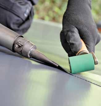
19 Sealing along parapets and upstands Use Sarnaplast Surfaces must be clean, dry and free of dust and dirt. G/S (PVC) surfaces must be primed with Sarnafil Primer 110 before sealant is applied. In locations where Sarnaplast 2235 has to adhere to Sarnafil TC Sarnafil Primer T 501 must be used. Sealant pointing with adhered Sarnafil (e.g. around rooflights): Apply Sarnafil Primer 110 (G/S) or T 501 (TC) along the frame edge and allow to evaporate. Form an angled bead of sealant using Sarnaplast To ensure adhesion to both faces, apply the appropriate Sarnafil Primer to contact areas. 19


 Fill space between penetration and membrane with sand")
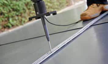
20 Allow Sarnafil Primer to evaporate Sealing Pipes and Penetrations Apply Sarnaplast 2235 and tool to form a concave groove. Sealing with jubilee clips (e.g. with penetrations) Prime the area to be sealed with the appropriate Sarnafil Primer. Insert Sarnaplast 2235 between the pipe and the Sarnafil waterproof flashing. With a jubilee clip secure the Sarnafil over the Sarnafil 2235 sealant. Sealing with Sarnaplast 2005 (Pitchpot detail) Fill space between penetration and membrane with sand filler to within 10mm of top of membrane then fill 10mm gap with Sarnaplast 2005 and tool to seal around the penetration. 20


21 1.3 Vapour Control Layers Sarnavap vapour control layers Sarnavap vapour control layers are particularly suitable for lightweight structures and achieving airtight seals at penetrations and perimeters. The Sarnavap product range includes the following: 1. Sarnavap 500E*, 1000E & 2000E 2. Sarnavap jointing tape 3. Sarnavap 5000E SA (Self Adhesive) * Note - Sarnavap 500E is not suitable for use with Sarnafil TC membranes Where structures are not airtight, the vapour control layer can also act as an air barrier layer. On flat surfaces Sarnavap is overlapped by 100mm and joined together with Sarnavap jointing tape for Sarnavap 500E, 1000E & 2000E polyethylene vapour control layers and self-adhered laps when using Sarnavap 5000E SA. The Sarnavap vapour control layer must be sealed at all perimeters and around penetrations. Such airtight joints are achieved with Sarnavap jointing tape for polyethylene vapour control layers or self-adhered when using Sarnavap 5000E SA. 1.4 System Constructions Sarnafil G/TCG, loose laid system Sarnafil G or TCG should be unrolled flat without waves or creases and be positioned to overlap by 80mm. The overlapped sheets must be welded immediately (on the same working day) and the loose laid Sarnafil ballasted as soon as possible. 21


22 Warm ballasted flat roofs with protective layer of round gravel or paving: Sarnafil S/TCS, Sarnabar System Install Sarnavap Install Insulation Install Membrane Install a protective layer on top of the Sarnafil G/TCG sheeting (e.g. Sarnafil Protection Sheet or Type T fleece, depending on guarantee requirement). Install a protective covering of either: 50mm thick 20-32mm diameter, well rounded, ovoid shaped stones/ pebbles washed free of sand and fine particles, evenly spread. Or Lay minimum 50mm thick precast concrete paving slabs, installed on proprietary support pads. (e.g. Sarnapad Paving Supports) Unroll the Sarnafil S or TCS roof covering, overlap by 80mm, weld immediately and fix to the substructure by means of Sarnabars. The type of fastening and tooling will be advised by Sika Limited. It is essential the correct fasteners and tooling are used. If in any doubt contact Sarnafil Technical Services or the Sika Roofing Applications Department. In systems using a metal deck Sarnabars must be installed at right angles to the deck. The perimeter bar ends must be secured with the SBT Row Termination washer/bar End washer. For protection fasten a pad of Sarnafil under bar end and washer. Fold back the pad over the bar end and washer and weld together. Leave a 10mm clearance between bar ends. File off barbs from cut ends. Cover the bar ends with a piece of Sarnafil and weld. Do not fasten in hole nearest bar end. Important If using the SBT fastener the membrane must be pre-punched using the SMP tool. 200mm Joint 10mm Piece of Sarnafil G/S 22


23 1.4.3 Sarnafil S/TCS, Sarnafast System After installation the Sarnabars must immediately be weathered with a 200mm wide Sarnafil coverstrip. Tack the Sarnafil coverstrip as closely as possible to the Sarnabar and weld to the Sarnafil S/TCS roof membrane. At upstands and at all penetrations (e.g. rooflights), the Sarnafil S/TCS membrane must be secured with a Sarnabar. The 4mm dia. Sarnafil welding cord secures the Sarnafil roof covering against tearing and peeling off by wind uplift. Introductory note: The following working guidelines apply only to the Sarnafast lap fastened system. In systems using a metal deck Sarnafil S or TCS, must always be installed at right angles to the deck direction. Sarnafil S/TCS is fixed by means of the Sarnafast fasteners along the marked line, 30mm from the edge of the membrane. The spacing of the fasteners is in accordance to the Sarnafil project specific calculations carried out by Sika Limited. Unroll the next Sarnafil S/TCS sheet and overlap along the marked line (120mm from the edge of the membrane). Important The Sarnafast fasteners must be installed with the correct tooling. Incorrect positioning and fixing of the fasteners will compromise the design load of the system! Correctly anchored fastener: The barbed washer must be level with the Sarnafil S/TCS. 23


24 Important: When using the SFT or SBT fastener the membrane must be pre-punched with the SMP tool! In corners, perimeters and other areas where additional fastening is required, intermediate rows of Sarnafast fasteners are installed through the pre-punched Sarnafil S/TCS membrane. Cover the rows of Sarnafast fasteners with a 200mm wide Sarnafil coverstrip and weld on both sides. The spacing of the fasteners is in accordance to the Sarnafil project specific calculations made by Sika Limited. Alternatively 1m wide Sarnafil membrane may be used overlapping and welding as previously described. At upstands and at all roof penetrations (e.g. rooflights), the Sarnafil S/TCS membrane must be secured with Sarnabars. The appropriate 4mm dia. Sarnafil welding cord secures the Sarnafil membrane against tearing by wind uplift. Important: All Sarnafast fasteners required according to calculations must be fixed immediately after the Sarnafil S/TCS membrane has been installed. Failure to do so may result in permanent membrane deformation. Sarnafil S/TCS must be hot air welded. All welding on the flat roofing should generally be carried out with the Sarnamatic automatic welding machine (according to the installation instructions for Sarnafil), however the use of an alternative welding machine or hand welding may be acceptable for S (PVC) only. Refer to the System Optimisation #2 and the Sarnafil project specification for details. The welding quality is of vital importance with the Sarnafast system. Always carry out peel tests! 24
25 Sarnafast Seam Welding (System Optimisation # 2) The use of hand welding, Leister Varimat or the Sievert automatic welding machines in the Sarnafast system, is acceptable for Sarnafil S327-12EL or S327-15EL only and on roofs which meet the following criteria; Maximum q figure* of 1.2kN/m² or less Roof pitch below 5 degrees** 10 or 15 year guarantee requirement The use of a Sarnamatic automatic welder is still required where: Sarnafil S327-18EL, S327-20EL or Sarnafil T/TC membranes are used in the Sarnafast system Where roofs have a q figure* above 1.2kN/m² Where Roof pitch is above 5 degrees** Where a 20 or 25 year guarantee is required * The q figure can be found in the wind uplift section of the Sarnafil project specification. ** On projects where the roof is above 5 pitch please consult Sarnafil Technical Services Department for a project specific wind uplift calculation, as it may be possible to extend the use of hand welding or alternative automatic welding machines Sarnafil G, Adhered system Sarnafil G410-ELF (Felt) with Sarnacol 2142S This adhesive is designed for adhering felt-backed Sarnafil G to standard insulations and substrates. Adhering Sarnafil G410-ELF by means of Sarnacol 2142s is particularly suitable for re-roofing over old bitumen waterproofing (Not suitable for re-roofing over synthetic, rubber or ECB roofing). Substrate preparation (re-roofing): Clean with a broom. Remove any oil and grease. Cut open any blisters in the old waterproofing and repair. The safety of the existing roof assembly in terms of wind suction must be ensured. Any insufficiently secured sections or components (e.g. chippings, slating etc.) must be removed to provide a smooth surface. The curing of Sarnacol 2142s requires moisture. The base layer may therefore be slightly moist (no puddles). If the relative humidity is below 35% moisten the adhesive after it has been applied. Peelstop protection must be provided at all upstands and roof penetrations, as work proceeds. 25

26 Adhering Sarnafil G410-ELF: Use Sarnacol 2142s only at temperatures above +5 C. Use only on slopes less than 10. Lay out and align Sarnafil G410-ELF with the felt-free edge along upstands. From the end of the run fold back Sarnafil G410-ELF to approximately half-way. Using a suitable roller apply Sarnacol 2142s evenly over the surface exposed by the folded back Sarnafil run. Roll the Sarnafil G sheet immediately into the wet adhesive. Press down the Sarnafil G410-ELF with a weighted roller (min 50 kg). According to site conditions (roof geometry) adjoin the next Sarnafil sheet at the end of the bonded membrane to form a butt joint or lay the following rolls alongside with overlapped joints. Welding of Sarnafil G410-ELF: The adhered Sarnafil G may be welded together after the adhesive bond is sufficiently strong. Butt joints should be covered with a Sarnafil G coverstrip welded on either side. Peelstop protection must be provided at all upstands and roof penetrations, as work proceeds. Sarnafil G410-ELF (Felt) with Sarnacol 2170 Adhere only to solvent resistant, dust-free surfaces. Using a Sarnafil roller apply a priming coat of Sarnacol 2170 on the roof surface and allow to dry. Lay out Sarnafil G410-ELF, align and take back to approximately half its length. Apply a second coat of Sarnacol 2170 to the roof surface. Roll Sarnafil G410-ELF immediately into the wet Sarnacol 2170 and press down using a weighted roller (50kg). Take back the other half of the membrane and repeat the procedure. Peelstop protection must be provided at all upstands and roof penetrations. 26

. Take back the other half and proceed as above.")

27 Sarnafil G410-EL with Sarnacol 2170 Using a Sarnafil roller apply a priming coat of Sarnacol 2170 to the roof surface. On absorbent surfaces it is recommended that a second priming coat be applied and allowed to dry completely. Prime only that area of the roofing where membrane will be laid on the same day. Lay out Sarnafil G410-EL, align and take back to approximately half its length. Depending upon the ambient temperature, apply Sarnacol 2170 in stages, allow to dry. Areas to be welded must be kept free of adhesive! Carefully roll back Sarnafil G410-EL and press down using a weighted roller (approx. 50kg). Take back the other half and proceed as above. Welding membrane adhered with Sarnacol 2170: When solvent based adhesives are used, the Sarnafil G membrane should be welded either immediately or not until 7 to 8 hours later. Peelstop protection must be provided at all upstands and roof penetrations. Important If using the SBT fastener for Peelstop the membrane must be pre-punched using the SMP tool. The weighted roller must be used on adhered systems (min 50 kg). 1.5 Procedures Inside Corner with Horizontal Crease G/TCG Membranes Coat the upstand and the Sarnafil flashing strip with the appropriate Sarnacol adhesive and allow to evaporate. Work into and around the internal angle and adhere. Dress Sarnafil membrane into the angle. 27


")

28 Important: Adhere the flashing strip neatly along all edges. 50 m m Form 45 mitre. Cut the gusset (hatched area) 50mm short from the corner. Pre-weld the gusset. Weld lower lap. 28
.")


29 Heat up the remainder of the gusset and weld together (20mm nozzle). Dress the welded Sarnafil pocket down for a few seconds. Carefully lift the unwelded Sarnafil overlap and hot air weld starting from the pocket side. Finish-weld from the corner outward Inside Corner with Vertical Crease G/TCG Membranes Inside corners with a vertical crease may be formed either directly from the Sarnafil membrane of the roof surface which is raised to form an upstand, or from the Sarnafil flashing strips. 29


30 First cut the Sarnafil flashing strips to fit, glue into position without creasing on the upstand and weld to the Sarnafil membrane on the roof surface. Cut and glue into position the second Sarnafil flashing strip on the upstand so that the overlap measures the same on the roof surface as in the corner. An upright crease is formed. Tack-weld the Sarnafil flashing strip to the Sarnafil membrane on the roof surface, into the groove and onto the vertical area, and weld the crease shut. Weld the Sarnafil flashing strip in the overlapping area to the first Sarnafil flashing strip and to the Sarnafil membrane on the roof surface. Starting from the vertical corner area, weld the closed Sarnafil pocket to the Sarnafil upstand to form a watertight seal (preliminary and final welding), complete by welding the vertical overlapping area. 30


31 1.5.3 Outside Corner G/TCG Membranes Apply appropriate Sarnacol adhesive to the Sarnafil flashing strip, allow the adhesive to evaporate and bond the Sarnafil strip to the dry Sarnacol coated upstand. 10 mm Make a cut in line with the corner, stopping 10 mm short of the corner itself. Apply hot air onto the Sarnafil at the corner to reactivate the Sarnacol adhesive. Dress the flashing strip around the corner without wrinkling. Weld the Sarnafil flashing overlap to the Sarnafil membrane on the roof surface. 31


32 Cut out the corner patch approx. 50mm larger. Then, round-off the corner which is to be positioned at the vertical edge. Heat and stretch the rounded corner of the Sarnafil corner patch. Tack-weld corner patch. Align patch and lower edge of upstand flashing strip. Weld the corner top-down... 32


33 ... then weld both sides of the rounded corner. Press down with the fingertips. Weld remaining sides of patch. Check all welds Upstands at Curved Parapets G/TCG Membranes Adhere the Sarnafil flashing strip vertically. Make regular folds in the lower edge (leave 40mm projecting above the upper edge). 33


34 Cut gussets at right angles 50mm to vertical face of trim. Weld the lower edge of the gusset to the roofing membrane. Weld the overlapping gussets. Continue welding segments until the whole Sarnafil strip has been welded to the Sarnafil membrane on the roof surface. If necessary weld an additional Sarnafil flashing strip over the cut area. 34


35 1.5.5 Sarnafil T prefabricated corners C1/125 C2/125 L=125mm Sarnafil T prefabricated corners may be fitted on either side. Type C 1/125 for the upper outside corner, at the top of the parapet for the lower inside corner, in the transition area to the roofing Type C 2/125 for the lower outside corner, in the transition area to the roofing, e.g. at chimneys for the upper inside corner, in the transition area at the top of the parapet Inside Corner with Prefabricated Sections Fashion joint or perimeter flashing with Sarnafil strips as illustrated Position the Sarnafil prefabricated corner Type C1/125 and weld to the Sarnafil parapet strip. Always weld from the inside edge outwards or upwards, to the right or left respectively. The Sarnafil prefabricated corner Type C/125 offers an economic and secure method of forming inside Corners. 35


36 1.5.7 Outside Corner with Prefabricated Sections Fashion joint or perimeter flashing with Sarnafil strips as illustrated Position the Sarnafil prefabricated corner Type C 2/125, tack into the inside edge and onto the vertical face and finally weld to the Sarnafil flashing strip.always weld from the edges outwards or upwards, to the right or left respectively. The Sarnafil prefabricated corner Type C 2/125 offers an economical and secure method of forming outside corners. 36

 and connecting plate (2) to the substrate (inserting Sarnafil sealing strip).")


37 1.6 Standard Details Sarnametal Roof Trims mm ~20 mm 3 General principle: It is essential to use the appropriate Sarnametal, G/S or T/TC. Sarnafil sealing strip must be used to ensure a waterproof joint between the wall and the Sarnametal, which must be securely fastened to withstand wind forces. Longitudinal joints: Fix the Sarnametal (1) and connecting plate (2) to the substrate (inserting Sarnafil sealing strip). Slide on the next Sarnametal profile (3) and fix through the connecting plate to the supporting structure. The open joint between the two sections should be a min. of 3mm. Cutting to fit internal corners: Mark mitre on the Sarnametal and cut to size. Bend to fit the corner and fix to the substrate. Cutting to fit external corners: Mark mitre at right angles and cut open. Bend the Sarnametal and fix to the substrate. Cover the exposed area of the corner by slipping a section of Sarnametal underneath. Adhere flashing to substrate approx. 50mm back from trim edge. Weld Sarnafil G/TCG approx. 10mm back from face of trim mm Longitudinal joints: 1. Connecting plate 2. Sarnametal profile 3. Adhesive tape over expansion joint 4. Sarnafil G/TCG strip, welded only along the edge (20mm on both sides) to the Sarnametal 5. Sarnafil G membrane, welded to Sarnametal. Note: Trims greater than 55mm in depth require face fixing as per the Fixing of Sarnametal trims section. 37


 Glue down")

38 Internal Corner (Proceed with the internal corner as described previously) Cut the Sarnafil G/TCG flashing strip, adhere to the substrate and weld to the Sarnametal as shown in the illustration. Do not apply adhesive Carefully cut the Sarnafil G/TCG corner patch as shown, then heat and stretch the inside, rounded corner. Neatly weld down the Sarnafil G/TCG corner patch and round off the outer corner of the Sarnafil G/TCG corner patch. External Corner (Proceed with the external corner as described previously) Glue down the Sarnafil G/TCG flashing strip, keeping the area shown free of adhesive to allow welding, and cut open the corner to a distance of 50mm above the top of the parapet (formation of crease). Glue the adhesive coated Sarnafil G/TCG flashing strip along the lower edge area, to the parapet and to the Sarnametal, mark as shown, cut to size and 38


39 weld to the Sarnametal. Cut the projecting side of the Sarnafil flashing strip as illustrated and weld together the crease in the Sarnafil G/TCG. Fold down the Sarnafil G/TCG flashing strip and adhere to the top of the parapet and the Sarnametal profile. Cut the Sarnafil G/TCG flashing strip as illustrated. Weld the crease and the Sarnafil G/TCG flashing strip to the previously welded Sarnafil G/TCG flashing strip or to the Sarnametal. For Curved Parapets Heat the 30mm of Sarnafil G/TCG protruding over the top of the parapet, stretch and glue into place. Cut the Sarnametal profile 39
 or Sarnacol T660 (TCG).")


40 and fasten securely to the parapet so that it will withstand wind forces SikaBond Adhesives SikaBond SikaBond AT- Metal Cut a strip of Sarnafil G/TCG to fit the top of the parapet and adhere with Sarnacol 2170 (G) or Sarnacol T660 (TCG). Weld the Sarnafil G/TCG strip to the Sarnametal and the Sarnafil G/TCG flashing membrane. The use of SikaBond gun grade adhesives can reduce or eliminate the need for mechanical attachment of Sarnametal trims or when attaching galvanised steel hard edges over insulation boards. These SikaBond adhesives are completely compatible with both Sarnafil G/S and TCG/TCS membranes and will be covered under the Sarnafil guarantee when purchased from Sika Sarnafil for use in the applications as shown. For uses outside the Sarnafil System these applications are undertaken at the Roofing Contractor s own risk and covered by standard Sika terms and conditions of use. SikaBond AT-Metal is an adhesive for both the internal & external bonding and sealing of metal to nonporous substrates. It achieves a strong adhesion to non-porous substrates, especially aluminium, copper, galvanised steel, stainless steel, etc. and many plastics (PVC, powder coatings, etc.) Substrates must be clean and dry, oil and grease free, free of dust and loose or friable particles. Because of the variability of substrates, SikaCleaner 205 may have to be used to ensure that the surfaces to be bonded are sufficiently clean. SikaPrimer N3 may also be required when bonding to some substrates. 40


41 SikaBond AT- Universal SikaBond AT-Universal is a multi-purpose adhesive for the internal & external bonding and sealing of metal and other construction materials. It achieves a strong adhesion to many substrates, including PVC, GRP, wood, ceramics, tiles, bricks, concrete, aluminium, stainless steel etc. Substrates must be clean and dry, oil and grease free, free of dust and loose or friable particles. SikaCleaner 205 may have to be used to prepare the surfaces to be bonded. SikaPrimer N3 may also be required when bonding to porous substrates. Because of the variability of surfaces the Roofing Contractor should ascertain if SikaCleaner 205 or SikaPrimer N3 is required, by carrying out an adhesion test. Both products are applied using a special pre-cut nozzle to create a 6mm triangular shaped central bead to the rear of the Sarnametal, which when compressed against the bonding surface, will produce a 20mm wide wet bead. Based on this bead size, the approximate adhesive consumption will be 8 linear metres per 300ml cartridge. Sarnametal Detail 1.1 or A 6mm triangular shaped bead of either SikaBond AT Universal or SikaBond AT Metal (as appropriate) is applied to the vertical leg of the Detail 1.1/1.3 using the special nozzle provided. Max depth of vertical leg is 100mm. 2. The Detail 1.1/1.3 is pushed into place against the hard edge, compressing the bead to 20mm wide before mechanically fastening the top leg only. No metal butt straps, cleats or face fixings are required. 3. The SikaBond AT Universal or SikaBond AT Metal will grab instantly, with the bond strength increasing through the curing period. The curing rate is subject to air temperature and relative humidity. Notes: Not to be used on trims with a vertical leg greater than 100mm. 41


 is applied to the rear of the Detail 2.8 using the special nozzle provided. 2. The Detail 2.")
42 Sarnametal Detail 2.3 A 6mm triangular shaped bead of either SikaBond AT Universal or SikaBond AT Metal (as appropriate) is applied to the rear of the Detail 2.3 using the special nozzle provided. The Detail 2.3 is pressed firmly against the substrate compressing the bead to 20mm wide. The SikaBond AT Universal or SikaBond AT Metal will grab instantly, with the bond strength increasing through the curing period. The curing rate is subject to air temperature and relative humidity. No need for the sealing strip to be installed under the Sarnametal trim as the SikaBond provides a seal to the vertical face. Sarnametal Detail A 6mm triangular shaped bead of either SikaBond AT Universal or SikaBond AT Metal (as appropriate) is applied to the rear of the Detail 2.8 using the special nozzle provided. 2. The Detail 2.8 is pushed into the chase in the brickwork and pressed firmly against the substrate, compressing the bead to 20mm wide. 3. The SikaBond AT Universal or SikaBond AT Metal will grab instantly, with the bond strength increasing through the curing period. The curing rate is subject to air temperature and relative humidity. 42
 membranes Sarnafil T lightning conductor clips heat welded to Sarnafil TC (FPO)")


43 1.6.3 Lightning Protection Perimeters with Gravel Stops The lightning conductor tape can be attached to Sarnafil G/S or TCS/TCG with either of the following methods: Sarnafil G/S lightning conductor clips heat welded to Sarnafil G/S (PVC) membranes Sarnafil T lightning conductor clips heat welded to Sarnafil TC (FPO) membranes Sarnafil membrane straps 150mm x 50mm welded either side of the conductor on a sacrificial Sarnafil pad 300mm x 300mm at max 1.0m centres Installing the gravel stops: The gravel stop is secured every 800mm to the Sarnafil membrane by means of the Sarnafil gravel stop pads. If the roof slope is between 1 and 8 the fixing pads should be installed with one at either side of the joint. For roofs over 8 a more substantial support will be required. Gravel stop protruding to the inside: If the gravel stop protrudes to the inside, then both the protective and the wear surface may be fitted right up to the outer edge of the roof. The face of the gravel stop is hidden. This type of installation is particularly suitable for flat roofs which are to be walked on. Gravel stop protruding to the outside: If the gravel stop protrudes to the outside, a ledge of approx. 30mm is created and the entire gravel stop remains visible. This type of installation is particularly suitable for flat roofs with a protective gravel layer. 43
 or Sarnacol T660 (TCG) at")
.")


44 1.6.5 Rooflight Adhere two Sarnafil G/TCG strips with Sarnacol 2170 (G) or Sarnacol T660 (TCG) at opposing sides of the rooflight (ensuring there are no air pockets). Mark and cut the corners as illustrated. Heat the Sarnafil overlap and adhere (without air pockets) round the rooflight edges. Mark the adhesive areas on the two remaining, opposing Sarnafil G/TCG strips, so that the overlaps to be welded are kept free of adhesive. Adhere the Sarnafil G/TCG strips (without air pockets). 44


45 and trim as illustrated for the welding of the overlap. In the lower corner area 20mm of the Sarnafil material is available for the welding by way of the thumb tab. Starting from the thumb tab carry out the pre-weld along the vertical weld seam and then the finishing weld, taking care that the equipment is held correctly. Important: The finishing weld of the thumb tab should be left until last. Round off the corners of the horizontally projecting Sarnafil G/TCG strip and trim off excess material. Weld the corner seam. 45


.")


46 Important: The Sarnafil G/TCG overlap must also be welded at the bottom. 5 m m Weld the thumb tab protruding at the lower corner by pressing down the heated Sarnafil material. If required, the mitre joint may also be cut parallel to the upstand (see illustration). The illustration of the finished rooflight shows the two methods of execution: the left-hand corner with 45 mitre the corner in the foreground with parallel mitre The upper open edge and the joint of the Sarnafil G/TCG to the rooflight frame are formed using Sarnaplast 2235 (see Sealing along parapets and upstands). 46
 Extend the lines of the sides (Intersection C) With radius CB lay off the circle s segmental arc of 1/3, 1/4 or 1/5 resp.")
 Allow 30 to 50 mm for the segment overlap and cut out the Sarnafil G/TCG segment Copy the segment and cut out the remaining 2, 3 or 4 Sarnafil")
 or Sarnacol T660 (TCG).")
47 B E A C 30mm Overlap 30mm Overlap D F Round, Conical Rooflight Round, conical rooflights are covered by 3, 4 or 5 Sarnafil G/TCG segments cut to the following pattern: Mark out the cross-sectional area of the cone (Points A, B) Extend the lines of the sides (Intersection C) With radius CB lay off the circle s segmental arc of 1/3, 1/4 or 1/5 resp. of the lower circumference (Point D) Mark out 30 to 50mm for the overlap on the roof area (Point E) (depending on the size of the cone) With radius CE lay off the circle s segmental arc up to the intersection of the extended connecting line CD (F) Allow 30 to 50 mm for the segment overlap and cut out the Sarnafil G/TCG segment Copy the segment and cut out the remaining 2, 3 or 4 Sarnafil G/TCG segments. A strip of Sarnafil G/TCG may be used for drawing the segmental arcs of the circle. Form the Sarnafil G/TCG flashing strip along the base to fit the light cone. Evenly heat and stretch the overlaps of the Sarnafil G/TCG segments for the connecting seam to the roof surface. Coat the Sarnafil segments with Sarnacol 2170 (G) or Sarnacol T660 (TCG). Important: The Sarnafil overlaps to be welded must be kept free of adhesive. 47


.")


48 Adhere Sarnafil segments without creasing Sarnafil Rainwater Outlets Pre-weld the Sarnafil overlap to the membrane covering the main roof area and then complete the weld. Weld the vertical overlaps of the Sarnafil G/TCG segments. Terminate the upper edge using Sarnaplast 2235 (see Sealing along parapets and upstands). General principle: It is recommended SarnaDrain G/S or SarnaDrain T outlets are used as appropriate. The outlets should be secured to the structural substrate and Sarnafil welded directly to the flange. 48


49 Sarnafil G/S & T rainwater outlets Cut the hole in the Sarnafil membrane to suit. Weld Sarnafil membrane to the flange using the 20mm wide nozzle Scuppers, overflows and shute outlets Sarnafil Double L & Double L T rainwater outlets Cut the hole in the Sarnafil membrane to suit Weld Sarnafil membrane to the flange using the 20mm wide nozzle. Sarnafil G/S & T Overflows These rigid PVC or rigid Polypropylene overflows must be secured to the substrate. Sarnafil membrane is welded directly to the flange. Sarnafil G/S & T Scuppers and Shutes Cut two matching Sarnafil membrane pieces as illustrated. Weld the first Sarnafil piece to the bent plate. Weld the second piece overlapping the first. If the outlet is located in a corner the Sarnafil connecting piece may be welded on beforehand, prior to bending the flange, which simplifies the detail work. 49


50 1.6.8 Pipes/Penetrations Vent Pipe Flashing For Sarnafil TC membranes - Standard pre-formed vent pipe / post flashings are available. Cut a hole in the Sarnafil T roofing slightly larger than the outer diameter of the vent pipe Slide the Sarnafil T vent pipe flashing over the pipe and weld to the Sarnafil TC roofing. Fit the cap on the vent pipe. Alternatively, as for G/S membranes, flashing can be fabricated as required. Fabrication with Sarnafil G/TCG membrane: Cut a hole in the Sarnafil base sheet 10mm smaller than the pipe diameter. Slide the Sarnafil G/TCG apron over the pipe, thereby creating an upstanding safety rim, and weld to the base membrane. 50


51 Cut a Sarnafil G/TCG pipe flashing so that it overlaps by 30mm for the welded seam. Insert a 20mm wide Sarnafil strip, pull the pipe flashing tight and tack-weld. Trim the lower Sarnafil G/TCG overlap. Because of the inserted Sarnafil strip, the flashing can be removed easily and should now preferably be welded shut on a separate support. Heat the lower edge and weld the bottom of the seam. Evenly heat the bottom edge of the Sarnafil G/TCG. 51


52 and stretch by approximately 20mm Carry out pre-welding of the Sarnafil G/TCG pipe flashing to the Sarnafil G/TCG base sheet by pressing down with a finger and then complete the weld using the Sarnafil pressure roller. Sarnafil G/TCG cap: Insert Sarnafil G/TCG, with the light side inwards, into the vent pipe, tack and cut the overlap back at an angle. Pull the tack-welded Sarnafil section out of the vent pipe and, working from the inside, weld up to a length of 50mm. 52


53 Insert the prepared Sarnafil G/TCG section into the vent pipe so that it protrudes from the latter by some 30mm. Bend the shaped section over the ventilation pipe and tack in several places to the Sarnafil pipe flashing. We recommend covering the ventilation pipe with a pipe cap. In this case the Sarnafil pipe flashing is cut flush with the top of the ventilation pipe. Pipes protruding at an angle Cut Sarnafil base to size. Cut pipe cut-outs exactly to size. Cut open base. Slide in. Weld. Note: Select position of cut in such a way that a strip can easily be welded over it. Cut development (30mm lap). Temporarily tack to pipe, mark bottom edge. 53


.")

54 unfasten temporary tacking, cut to size, heat and stretch bottom flashing lap. Overlap area for welding to Sarnafil TG Plate Constant Force Post Tack to pipe. Weld the long lap. Weld bottom flashing lap to the base. Starting at the bottom and working upwards, weld the overlap of the Sarnafil pipe flashing. Suggestion: The upper, open edge may be finished by fitting a jubilee clip and sealing with Sarnaplast 2235 (see Sealing along parapets and upstands). The Sarnafil Constant Force post is currently the only fall arrest system that can be installed above a finished Sarnafil roof, easing installation and enabling retrofitting to any metal, concrete or timber decked roof. Due to the Health and Safety requirements relating to fall arrest systems the Sarnafil Constant Force post can only be installed by a Latchways trained operative. 54


55 Sarnafil Liquid Detailing System The Sarnafil liquid detailing system can be utilised for a number of difficult detailing situations. It should however only be used in strict acordance with Sika Sarnafil instructions and in consultation with the Sika Roofing Applications Department. System Membrane Cleaner Primers LAM Sarnafil G/S membranes (Up to two years old only). Not to be used on Sarnafil G476 membrane! Products Sarna Cleaner Sikalastic -600 PVC Primer Sikalastic Metal Primer Sika Concrete Primer Sikalastic -621 TC first layer ( 1l/m 2, 1.4 kg/m 2 ) Sika Reemat Premium Sikalastic -621 TC second layer ( 1.0 l/m 2, 1.4 kg/m 2 ) The two layers must be different colours to ensure the first layer is totally covered! Product Description Packaging Shelf Life Sikalastic -621 TC Slate Grey (Dark Grey) - nearest RAL 7015 and Shale Grey (Light Grey) - nearest RAL C moisture triggered polyurethane 5 Ltr 12 months (see product Data sheet) NB: Both colours are required! Sika Reemat Premium Glass Fibre Mat 0.3m x 150m Should not expire (see Product Data Sheet) 55


 12 months (see Product")
56 Product Description Packaging Shelf Life Sarna Cleaner Solvent based cleaner 5 Ltr 12 months (see product Data sheet) Sikalastic 600 PVC Primer Sika Concrete Primer Sikalastic Metal Primer 1 Part solvent based polyurethane primer 2 Part solvent solvent based polyurea primer 2 Part amide curing solvent based primer 1Ltr bottle Two Part 1Ltr and 5 Ltr Two Part 5 Ltr 9 months (see Product Data Sheet) 12 months (see Product Data Sheet) 12 months (see Product Data Sheet) 56


 50mm Brush")


57 Product Description Packaging Shelf Life Sika Flexistrip Preformed strip sealant reel on a paper release liner 0.05 x 15m (see product Data sheet) 50mm Brush 70mm Brush Tiger Stripe Roller Refill 100mm Foam Roller Refill 100mm Each Each Each Each Radiator Frame Short for 100mm Rollers Each 57


58 Product Description Packaging T Prep Cloths Pack 150 Tesa UK Ltd 50mm wide 50650/50600 tape Polyester tape coated with silicone adhesive This product is not available from Sika Limited but from Tesa UK Ltd distributors. Contact Tesa UK Ltd for further information: (01908) Preparation and Priming All surfaces where Sikalastic -621 TC is being utilised must be sound, of sufficient strength, clean, dry and free of all contamination such as oil, grease, coatings etc. Certain substrates and Sarnafil G/S membranes require the appropriate Sika Primer as in the table below. Please consult the most recent Product Data Sheet for further details: Substrate Primer Consumption Primer (ml/m 2 ) Cementitious substrate Brick and Stone Asphalt Bituminous felt Bituminous coatings Metals, ferrous or galvanise metals, lead, copper, aluminium, brass or stainless steel Sika Concrete Primer May require Sika Concrete Primer Primer not usually required, subject to surface assessment tests Primer not usually required, subject to surface assessment tests Primer not usually required, subject to surface assessment tests Sikalastic Metal Primer 150 Subject to nature of substrate Timber Sika Concrete Primer Paints Sikalastic Metal Primer Sarnafil G/S membranes Sikalastic 600 PVC Primer Existing Sikalastic Membrane Sika Reactivation Primer or Methylated spirit* * Consult Sika Roofing Applications Department. Subject to nature of substrate Subject to nature of substrate


59 All surfaces where Sikalastic -621 TC is being utilised must be prepared so they are sound, of sufficient strength, clean, dry and free of all contamination such as dirt, oil, grease etc. The surface should then be primed where necessary with Sikalastic Metal Primer or Sika Concrete Primer 24 hours prior to the application of the first layer of Sikalastic -621 TC. Any bolt heads must be smoothed over with Sika Flexistrip prior to the application of the first layer of Sikalastic -621 TC. Sika Flexistrip must not come into contact with Sarnafil G/S membranes! Detailing Where Sarnafil membrane is taking place any penetration in a mechanically fastened system (Sarnabar and Sarnafast) and any penetration 400 x 400mm or with a diameter of 400mm in an adhered system must be mechanically restrained. Fix the membrane a minimum of 50mm from the edge of the abutment with Sarnabar and PVC cord (mechanically fixed Sarnabar system) or Peelstop for adhered systems. Place 50mm wide Tesa UK Ltd 50600/50650 masking tape directly onto the Sarnabar/Peelstop in order to provide a suitable surface for the Sikalastic -621 TC. For the Sarnafast system having installed the membrane to the edge of the abutment, mechanically fix the membrane with the appropriate washers (mechanically fixed Sarnafast system). 59


60 Place 50mm wide Tesa UK Ltd 50600/50650 masking tape directly onto the SFTs/Washers in order to get a smoother surface for over coating. Install masking tape a minimum of 150mm from the outside of the detail or the edge of the masking tape on any fasteners to be coated with Sikalastic -621 TC. Prepare the Sika Reemat Premium to the appropriate size prior to the application of the first layer of Sikalastic -621 TC. Ensuring that the Reemat is kept around 10mm from the masking tape. If required thoroughly clean the membrane with water and detergent to remove any dirt or grease Wipe the clean membrane once only with Sarna Cleaner (using T Prep Cloths). 60


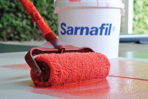
61 Wait a minimum of 5 minutes until dry and then apply Sikalastic -600 PVC Primer evenly by using a roller or brush ( foam roller recommended) at a consumption of g/m 2 then allow a minimum of 15 minutes to completely dry. Apply the first layer of Sikalastic -621 TC using at least 1L/m 2. The first layer must be a different colour to the top layer! Whilst the first layer of Sikalastic -621 TC is still wet strengthen it by inserting the Sika Reemat Premium Ensure that the Sika Reemat Premium is kept back about 10mm from the masked area so no strands of fibre are visible. The Sika Reemat Premium is completely embedded leaving the Sikalastic -621 TC with a shiny finish. Any overlaps of Sika Reemat Premium must be a minimum of 50mm. Check the coatings for pinholes and/or exposed Sika Reemat Premium and apply further Sikalastic -621 TC material to correct if necessary. Remove masking taped whilst material is still wet. Allow to dry for at least 6 hours and reinstall masking tape into same position. If any Sika Reemat Premium fibres are visible remove with sand paper and ensure the area is dust free prior to applying second layer of Sikalastic -621 TC. Apply a second layer of different colour Sikalastic -621 TC using the same consumption rate as the first layer. Ensure that the first colour is totally covered over. Again remove masking tape whilst coating is wet. On completion check for any pinholes voids or misses and spot treat as necessary. The second layer of Sikalastic -621 TC must be applied within 7 days of the first layer! If this cannot be achieved consult your local Field Technician for advice before going any further. 61


62 Example Applications The Sarnafil Liquid Detailing System can be utilised for a number of difficult detailing situations, such as those in the images below. However should you have any questions regarding the use of the Sarnafil Liquid Detailing System please contact your local Field Technician. Limitations Sarnafil G/S membranes (Up to two years old only). Not to be used on Sarnafil G476 membrane. The first and second layer of Sikalastic -621 TC must be different colours. Must not be used in inverted roof situations. Must not be used where standing water may occur. The Sarnafil Liquid Detailing System will only be covered for, 10 years with a corresponding 10 year Sarnafil Guarantee and for 15 years with a 15/20 or 25 year Sarnafil Guarantee. Air temperature must be between +5 C and +35 C; temperature is falling. If applied during rising temperatures pin holing may be caused by expanding air. Atmospheric humidity is at least 5% and less than 85%. Substrate temperature is between +5 C and +35 C. Ambient temperature during application must be at least +3 C above dew point. Pay attention to temperature fluctuation and direct solar radiation, which may influence application. Surface must be dry and substrate humidity is maximum 4% without emitting dampness. Do not use Sikalastic -621 TC for indoor applications or on sensitive buildings (hospital, schools, etc.) where vapours might be drawn into ventilation intakes (penetrating odour). Sikalastic -621 TC is not recommended for areas where frequent traffic may occur. If daily pedestrian traffic is unavoidable, Sikalastic -621 TC should be covered with an appropriate walkway system. Do not apply cementitious products (e.g. tile grout) directly over Sikalastic -621 TC. The second layer of Sikalastic -621 TC must be applied within 7 days of the first layer. If this cannot be achieved consult your local Field Technician for advice before going any further. Do not apply cementitious products (e.g. tile grout) directly over Sikalastic -621 TC. Please refer to the relevant and most recent Product Data Sheet for further and more detailed information. 62


63 1.7 Aesthetic Profiles For G/S membrane roofs only! Decor Profile Batten Profile Installation Lay out on the roof at the specified centres ensuring that the Décor Profile is tacked into position. Press down one side of the Décor Profile with a straight edge and hot air weld the wing on the opposite side then repeat on the other side. Join using the plugs supplied. If required finish end with a piece of membrane. A decor profile welding kit is available for the Sarnamatic 661 plus. Please consult the Sika Roofing Applications Department. For use on Sarnafil G/S PVC membranes only. Installation After completion of the adhered Sarnafil G410-EL/ELF Lead Grey roof (Batten profiles are not suitable for use on mechanically fastened membrane systems) lay out the Batten Profile at the desired centres ensuring that the Batten Profile is temporarily weighted in place. Press down one side of the Batten Profile with a straight galvanised metal plate and hot air weld the welding wing on the opposite side to the roof membrane. Repeat welding on the opposite side. Butt joint two or more lengths together using the 100mm long Batten Profile Jointing Piece (separate order item). Complete the length of Batten Profile with an end piece (separate order item) and tack it to the Batten Profile with a hot air gun. Continue working across the roof as described above. For use on Sarnafil G PVC Adhered membrane systems only. 63


64 1.8 Special Details Movement joint Connection to bituminous roofing Expansion above separate substructures Loop the vapour control layer in the gap. Install a compressible insulation strip so that it protrudes by some 20mm beyond the upper edge of the thermal insulation layer. Using Sarnabars, fix the Sarnafil membranes in the roof area on both sides of the joint. Secure the membranes against tearing using 4mm dia. Sarnafil welding cord. Cut the Sarnafil coverstrip and weld to the mechanically fastened Sarnafil membrane on the roof surface. On flat roofs with ballast, a protective layer must be provided in the expansion area. A joint chamber is required under utility coverings. All connections to bituminous roofing materials should normally be made by means of structural measures such as upstands and the like. Consult Sarnafil Technical Services. A temporary connection only between Sarnafil G/S membranes and a bituminous roof covering, may be achieved with Sarnafil G Consult Sarnafil Technical Services. 64
65 1.9 Safety/Control Day joints Day joints protect flat roof areas against water penetration when work is interrupted. Day joints to a bituminous vapour control layer: Bituminous vapour barrier strip (remove before work recommences) adhered to installed vapour control layer. 2. Retaining weight on Sarnafil membrane Day joints with Sarnavap vapour control layer on top of a level deck: 1. Sarnavap vapour control layer adhered to the deck by means of Sarnavap sealing tape. 2. Retaining weight on Sarnafil membrane Day joints with Sarnavap vapour control layer on top of profiled sheet metal: 1. Sarnavap vapour control layer 2. Retaining weight on Sarnafil membrane 65
66 1.9.2 Partitioning on bituminous vapour control layers Partitions are best arranged above high points of the deck. 1. Deck 2. Bituminous vapour control layer, fully adhered at least within the area of the partition 3. Thermal insulation layer, adhered or loose laid 4. Partitioning strip of Sarnafil G (yellow) or Sarnafil TCG, adhered with hot bitumen to the vapour control layer 5. Sarnafil membrane welded to the partitioning strip. 6. Sarnafil membrane welded to the Sarnafil field membrane


67 1.9.3 Flood Testing Flood testing the roof area is carried out preferably before the protective or wear layers are installed. This test provides for maximum reliability regarding the proper functioning of flat roofing and permits qualified acceptance/approval by the owner or main contractor. Important: The flood test does not absolve the contractor from checking every individual welded seam. Block the Sarnafil rainwater outlets by means of drain stops. General principle: The damming height must be selected to ensure that the water can always drain off before it seeps into any penetrations in the flat roofing! Wherever possible the water height should be at least 100mm. A water level of 100mm exerts a load of 100kg/m 2 on the substructure and supporting structure. Note: Always consult a structural engineer before flood testing. The flat roofing should be submerged for approx. 5 days under coloured water (fluorescine) and 67


68 must be checked daily for leaks, if inspection systems have been provided. The results of the flood test should be recorded in a report. Flat roofing without inspection systems cannot be properly checked during the flood test. However, the building interior should be inspected for leaks on a daily basis. After the submersion under water the flat roofing should be checked by means of cut tests at low points of the structure. 68
Construction. Sarnafil TS Polymeric membrane for roof waterproofing. Product Description
 January, 2009 Sarnafil TS 77-15 Polymeric membrane for roof waterproofing Construction Product Description Uses Characteristics / Advantages Approval / Standards Sarnafil TS 77-15 (thickness 1.5 mm) is
Roofing. Polymeric sheet for roof waterproofing. Product Description. Tests. Product Data Sheet Edition _1
 Product Data Sheet Edition 2014-09_1 Polymeric sheet for roof waterproofing Product Description (thickness 1.5 mm) is a Polyester reinforced, multi-layer, synthetic roof waterproofing sheet based on premium-quality
Roofing. Sarnafil S EL. Polymeric membrane for roof waterproofing. Product Description
 Roofing Product Data Sheet Edition 02.2015 Identification no: 02 09 01 01 201 0 120000 Version no. 04 Sarnafil S 327-12EL Polymeric membrane for roof waterproofing Product Description Sarnafil S 327-12EL
VINITEX INSTALLATION PROCEDURES
 VINITEX INSTALLATION PROCEDURES 1 INDex INTRODUCTION PAGE 2 HOT AIR manual WELDING PAGE 6 AUTOMATIC WELDING PAGE 10 WELDING TRANSVERSE JOINTS PAGE 13 T-JOINTS MULTIPLE WELDING SEAMS PAGE 15 PERIMETER
Construction. Polymeric membrane for roof waterproofing. Product Description. Tests
 Construction Product Data Sheet Edition: 27/01/2013 Identification no: 02 09 10 05 200 0 120000 Version: GCC Sarnafil TG 76-12 Felt Sarnafil TG 76-12 Felt Polymeric membrane for roof waterproofing Product
Construction. S-Vap 5000E SA Self-adhesive Vapour Barrier. Product Description
 Roofing Product Data Sheet Edition 11.2014 / xtra UK Identification no. 02 09 45 05 100 0 000019 Version no. 03 S-Vap 5000E SA Self-adhesive Vapour Barrier Product Description S-Vap 5000E SA is a multi-layer
Roofing. Sarnafil G EL Felt. Polymeric membrane for roof waterproofing. Product Description
 Roofing Product Data Sheet Edition 10.2012 Identification no: 02 09 01 01 341 0 120000 Version no. 06 Sarnafil G 410-12EL Felt Polymeric membrane for roof waterproofing Product Description Sarnafil G 410-12EL
ITEM 458 WATERPROOFING FOR STRUCTURES
 ITEM 458 WATERPROOFING FOR STRUCTURES 458.1. Description. This Item shall govern for the furnishing and placing of waterproofing on concrete and steel bridge decks of railroad structures and on other structures
Construction. Sarnafil G Felt. Polymeric membrane for roof waterproofing. Product Description
 Roofing Product Data Sheet Edition 03.2012 Identification no: 02 09 05 05 215 0 120000/1 Version no. 01 Sarnafil G 410-12 Felt Polymeric membrane for roof waterproofing Construction Product Description
INSTALLATION INSTRUCTIONS KÖSTER TPO
 INSTALLATION INSTRUCTIONS KÖSTER Contents Contents Basics Installation Products 4 KÖSTER Characteristics 5 Mechanical fastening 7 Full surface adhesion 8 Loose installation 9 Tools 10 Welding temperature
Part of the Sikaplan WT Membrane System
 System Product Data Sheet Edition: 10.2011 Identification no: 02 07 03 02 System Sikaplan WT Tape 200 System Part of the Sikaplan WT Membrane System Product Description Sikaplan WT Tape 200 is a high performance
Protan Exposed Membrane Roof. Your design - Our solution
 Protan Exposed Membrane Roof Your design - Our solution Exposed membrane roof The principle function of a roof is to provide durable protection against the external environment to a building. Unprotected
Outline NBS Specification. Protec System to PVC Single Ply (Waterproofing Only)
") Outline NBS Specification Protec System to PVC Single Ply (Waterproofing Only) This document is a guide to assist in the production of tender documents only and is not project specific. A site survey is
Outline NBS Specification Protec System to PVC Single Ply (Waterproofing Only) This document is a guide to assist in the production of tender documents only and is not project specific. A site survey is
Sarnavap 1000E is an unsupported vapour control layer based on PE-LD (Low Density Polyethylen).
.") Roofing Roofing Product Data Sheet Edition 06.2013 Version no. DE 01 English Vapour control layer Product Description Uses Characteristics / Advantages Tests is an unsupported vapour control layer based
Roofing Roofing Product Data Sheet Edition 06.2013 Version no. DE 01 English Vapour control layer Product Description Uses Characteristics / Advantages Tests is an unsupported vapour control layer based
Colphene BSW Training and Application Guide. Colphene BSW Waterproofing Membrane. 1. Prepare substrate
 Colphene BSW Training and Application Guide Colphene BSW Waterproofing Membrane. 1. Prepare substrate Substrate must be structurally sound. Surface must be free of voids, spalled areas, loose aggregate,
Gas Protection System Components
 Page 1 Visqueen Gas Protection Visqueen Building Products is recognised as the leader in the development, production and supply of high quality construction related ground gas protection membranes. The
Roofing. Carrier Membrane SA. Self-adhesive Carrier Membrane. Product Description. Tests. Product Data. Form. Storage
 Carrier Membrane SA Self-adhesive Carrier Membrane Product Description Carrier Membrane SA is a multi-layer self-adhesive membrane made of polymer modified bitumen with an aluminium foil/random fibre top
Standard specification for the application of Danosa Two-Layer waterproof roofing membrane to plywood & concrete surfaces.
 Standard specification for the application of Danosa Two-Layer waterproof roofing membrane to plywood & concrete surfaces. BRANZ Appraised No. 678 Ref: P3200 Rev 1 February 2016 Page 1 of 5 1.0 PREAMBLE:
Dynamic Bonding Systems B.V. A division of Dutch Bonding Group B.V.
 for the bonding of facade cladding with KOMO-certified bonding system Dynamic Bond METALS - HPL - FIBRECEMENT Dynamic Bond For panels up to the maximum diagonal. Based on MS-hybrid-polymers, one component.
84 Lapping & Jointing 86 Service Pipe Penetrations 87 Sealing to Cavity Wall Constructions 88 Protecting Membranes System Components.
 84 Lapping & Jointing 86 Service Pipe Penetrations 87 Sealing to Cavity Wall Constructions 88 Protecting Membranes 90 System Components installation/ SYSTEM COMPONENTS INSTALLATION ADVICE LAPPING and JOINTING
RUBBERGARD EPDM SA APPLICATION GUIDE
 RUBBERGARD EPDM SA APPLICATION GUIDE I. MEMBRANE APPLICATION... 2 A. MEMBRANE... 2 II. MEMBRANE ATTACHMENT... 2 A. MEMBRANE PREPARATION... 2 B. MEMBRANE APPLICATION... 2 III. SEAMING... 3 VI. MEMBRANE
SECTION MANUFACTURED ROOF EXPANSION JOINTS
 SECTION 07 71 29 - MANUFACTURED ROOF EXPANSION JOINTS PART 1 -GENERAL 1.1 RELATED DOCUMENTS A. Drawings and general provisions of the Contract, including General and Supplementary Conditions and Division
NBS SECTION J42 - SCOPE OF WORKS
 NBS SECTION J42 - SCOPE OF WORKS Section J42 deals with the installation of the Bauder Single Ply System, comprising single layer coverings of polymeric sheets, including vapour control layers and insulation
Part of the Sikaplan WT Membrane System
 Product Data Sheet Edition: 07.2011 Version 2011-10-19 Sikaplan WT Tape 200 Sikaplan WT Tape 200 Part of the Sikaplan WT Membrane System Product Description Uses Characteristics/ Advantages The Sikaplan
750ml INSTA-STIK roofing adhesive. Professional Roofing Adhesive
 750ml INSTA-STIK roofing adhesive Professional Roofing Adhesive INSTA-STIK roofing adhesive in a can: for highly portable and economical adhesion The 750ml INSTA-STIK roofing adhesive can has been designed
SECTION TPO WATERPROOFING MEMBRANE FOR FLAT ROOFS INSTALATION
 SECTION 07 54 23 TPO WATERPROOFING MEMBRANE FOR FLAT ROOFS INSTALATION PART 1 GENERAL 1.1 SECTION INCLUDES A. Waterproofing of flat and sloped roofs. Application by loose laying with ballast, mechanical
SECTION THERMOPLASTIC POLYOLEFIN (TPO) ROOFING PART 1 - GENERAL 1.1 RELATED DOCUMENTS
 ROOFING PART 1 - GENERAL 1.1 RELATED DOCUMENTS") SECTION 075423 - THERMOPLASTIC POLYOLEFIN (TPO) ROOFING PART 1 - GENERAL 1.1 RELATED DOCUMENTS A. Drawings and general provisions of the Contract, including Division 00 Bidding Requirements and other Division
SECTION 075423 - THERMOPLASTIC POLYOLEFIN (TPO) ROOFING PART 1 - GENERAL 1.1 RELATED DOCUMENTS A. Drawings and general provisions of the Contract, including Division 00 Bidding Requirements and other Division
INSTALLATION INSTRUCTIONS
 1 of 6 INSTALLATION INSTRUCTIONS IMPORTANT! Store the floorboards at room temperature for at least 48 hours, still in their packaging, prior to commencing installation. Ideal room temperature is 18-22
TUFF-TAC TM BRIDGE MEMBRANE INSTALLATION GUIDE
 5 pages TUFF-TAC TM BRIDGE MEMBRANE INSTALLATION GUIDE The following will describe the proper procedure to use when installing Tuff-Tac TM bridge deck membrane. The guide will cover recommended tools to
Construction. Sika-Trocal SGmA 1.5 mm. Polymeric membrane for roof waterproofing. Product Description
 Roofing Product Data Sheet Edition 03.2009 Identification no. 02 09 01 01 124 0 150000 Version no. 03 Sika-Trocal SGmA 1.5 mm Polymeric membrane for roof waterproofing Construction Product Description
TILING SPECIFICATIONS
 TILING SPECIFICATIONS SPECIFICATION NUMBER: NR204-16 PREPARED BY: Mike Cubley PREPARED FOR: Porcelain Plus ATTENTION: Kirk Pollock INSTALLATION: 712 Turner Floor and Wall Tiling Specification. M40 STONE/
Construction. High performance joint sealing system. Product Description 1 1/9. Product Data Sheet Edition 29th October 2015
 Construction Product Data Sheet Edition 29th October 2015 Sikadur-Combiflex SG system High performance joint sealing system Product Description The Sikadur-Combiflex SG system is a high performance joint
aquapanel InstallatIon GuIde
 Installation Guide AQUAPANEL BEFORE YOU START It s a good idea to stand the AQUAPANEL sheets in the area for 2 days prior to cutting and installing, to allow the sheets to breathe and reach moisture equilibrium.
INSTALLATION MANUAL. METAL INSULATED PANELS -ROXUL -Expanded Polystyrene
 INSTALLATION MANUAL METAL INSULATED PANELS -ROXUL -Expanded Polystyrene Insulated Metal Panels London Eco-Metal Manufacturing Inc. **Also see Eco-Metal s Handling Manual** These instructions are provided
Cold Work Cladding Fabrication & Application
 TRADE OF Industrial Insulation PHASE 2 Module 3 Substructures, Advanced Cold Work and Cladding UNIT: 4 Cold Work Cladding Fabrication & Application Produced by In cooperation with subject matter expert:
Worldwide Competence in Plastics. Development by professionals. The long-lasting roof system
 en austroplan TPO roof liners l Made of environmentally friendly TPO l High flexibility l Resistant to root penetration l Tearproof and weather resistant l Maintenance free l Long lifetime l Easy and safe
GRP Flat Roofing Edge Trims
 GRP Flat Roofing Edge Trims Compatible with GRP, rigid and flexible polyester, polyurethane, acrylic and alkyd systems. Trim Brochure and Technical Specification Guide General Information The Easy To Use
1-part elastic joint sealant and multipurpose adhesive
 Product Data Sheet Edition 31/10/2006 Identification no: 02 05 01 01 005 0 000001 1-part elastic joint sealant and multipurpose adhesive Construction Product Description Uses Characteristics / Advantages
Sika Sarnafil World Class Roofing and Waterproofing
 Roofing Technical Bulletin #04-10 To: Approved Applicators Sika Sarnafil Technical Staff Date: 06-01-10 From: Technical Services Department Re: Décor Installation Guidelines The successful installation
E. Section Polymer Modified Cement Waterproofing. K. Section Sub drainage: Foundation perimeter drainage.
 DELTA -DRAIN Section 07 10 00 Dampproofing and Waterproofing PART 1 GENERAL 1.1 SECTION INCLUDES A. Below grade drainage sheets. B. Plaza deck and planter drainage sheets. 1.2 RELATED SECTIONS A. Section
H series. for upper balconies DN 100. DN 100 Vers. a X X. Partial unit Side drain
 instructions LORO direct balcony drains with connecting sleeve, EN 123-compliant, Steel, hot-dip galvanised, additionally coated, and DN 100 System overview for balcony storeys one-piece for upper balconies
Industry Standard Terms & Definitions Of The Steel Deck Institute
 Industry Standard Terms & Definitions Of The Steel Deck Institute A specialized set of jargon to describe common terms used by manufacturers and other professionals associated with the usage of Steel Deck
1 Firestone EPDM Roofing Systems
 1 Firestone 1. Firestone EPDM Systems To ensure a long-lasting, trouble-free roof today, it is not sufficient to manufacture high quality roofing membranes. Experience learned that roofing membranes need
GenFlex EZ TPO Peel & Stick SA (HW) APPLICATION GUIDE
 APPLICATION GUIDE") GenFlex EZ TPO Peel & Stick SA (HW) APPLICATION GUIDE I. MEMBRANE APPLICATION... 2 A. MEMBRANE... 2 II. MEMBRANE ATTACHMENT... 2 III. SEAMING... 3 A. SEAMING FOR GENFLEX EZ TPO PEEL & STICK SA (HW)...
GenFlex EZ TPO Peel & Stick SA (HW) APPLICATION GUIDE I. MEMBRANE APPLICATION... 2 A. MEMBRANE... 2 II. MEMBRANE ATTACHMENT... 2 III. SEAMING... 3 A. SEAMING FOR GENFLEX EZ TPO PEEL & STICK SA (HW)...
FIRESTONE ULTRAPLY TPO SA APPLICATION GUIDE
 FIRESTONE ULTRAPLY TPO SA APPLICATION GUIDE I. MEMBRANE APPLICATION... 2 A. MEMBRANE... 2 II. MEMBRANE ATTACHMENT... 2 III. SEAMING... 3 A. SEAMING FOR FIRESTONE ULTRAPLY TPO SA... 3 B. T-JOINT AREAS...
IKO Ruberseal EPDM Roofing System Guide
 IKO0317 April 2017 IKO Ruberseal EPDM Roofing System Guide IKO is a worldwide enterprise, with more than 3000 employees, and manufacturing plants in Canada, the United States, United Kingdom, Belgium,
Technical Service. INSTALLATION INSTRUCTIONS FOR TARAFLEX SPORT PRODUCTS over Gypsum base Products. This document refers to the following products:
 INSTALLATION INSTRUCTIONS FOR TARAFLEX SPORT PRODUCTS over Gypsum base Products This document refers to the following products: Product Width Width Ft. Installation direction Seams treatment Taraflex Surface
Caparol System PRO Data sheet
 System features Expanded polystyrene insulation Cost effective solution Excellent detailing options Proven technology Wide variety of colours Reliable protection and crack resistance Proven track record
SpaVault TM Installation Guide for Bullfrog Spas (7-10 x 7-10 x 38 )
") SpaVault TM Installation Guide for Bullfrog Spas (7-10 x 7-10 x 38 ) WARNING - When unpacking SpaVault, DO NOT discard styrofoam pieces, these are not packaging materials. Step 1 Excavation Important:
SpaVault TM Installation Guide for Bullfrog Spas (7-10 x 7-10 x 38 ) WARNING - When unpacking SpaVault, DO NOT discard styrofoam pieces, these are not packaging materials. Step 1 Excavation Important:
PLATON FOUNDATION WRAP
 DRAINAGE SOLUTIONS SINCE 1908 PLATON FOUNDATION WRAP RUGGED, DIMPLED HIGH-DENSITY POLYETHYLENE (HDPE) MEMBRANE THAT KEEPS FOUNDATIONS DRY ADVANCED TECHNOLOGY EASY INSTALLATION PROVEN PERFORMANCE ARMTEC.COM
1. Rubberized asphalt waterproofing membrane, reinforced. 2. Molded sheet drainage panels. 3. Insulation. 4. Plaza deck pavers.
 SECTION 071413 HOT FLUID APPLIED RUBBERIZED ASPHALT WATERPROOFING PART 1 GENERAL 1.1 SUMMARY A. Section Includes: 1. Rubberized asphalt waterproofing membrane, reinforced. 2. Molded sheet drainage panels.
FLUID APPLIED WATERPROOFING
 SECTION 07120 FLUID APPLIED WATERPROOFING PART 1 GENERAL 1.01 SUMMARY A. Related Sections: 1. 03300 - Cast-In-Place Concrete. 2. 09200 - Metal Studs, Metal Lath, Suspension Ceilings, Plaster, and Stucco.
1-part polyurethane pourable self levelling floor joint sealant
 Product Data Sheet Edition 29/03/2007 Identification no: 02 05 01 01 018 0 000001 1-part polyurethane pourable self levelling floor joint sealant Construction Product Description Uses Characteristics /
STEP UP SHOWER BASE INSTALLATION GUIDE FOR TIMBER AND CONCRETE FLOORS
 GUIDE FOR TIMBER AND CONCRETE FLOORS EDITION: APRIL 2016 IMPORTANT: This guide is for the installation of a Step Up shower base on a timber or concrete floor. If you require a walk in (flush with floor)
General Applications Before applying, mix the pre-measured catalyst* into Liquid Roof by following label directions.
 General Applications Before applying, mix the pre-measured catalyst* into Liquid Roof by following label directions. Surface Preparation: Surface to be coated should be clean, dry and structurally sound.
.1 Provide submittals in accordance with Section Submittal Procedures.
 Place D Orléans Transitway Section 07 13 52 1231 Place D Orléans Dr, Ottawa, ON. WATERPROOFING MEMBRANE City of Ottawa Project No. CR008042 Page 1 of 2 1 GENERAL 1.01 SUBMITTALS.1 Provide submittals in
Construction. High performance joint sealing system. Product Description. System Data Sheet Edition _1. 1 Sikadur Combiflex SG system 1/8
 System Data Sheet Edition 2012-05_1 High performance joint sealing system Construction Product Description Uses High performance joint sealing system for construction, expansion and connection joints as
Product Data Sheet Edition 25/01/2006. Sikasil WS-305. Product Description. Uses. Characteristics / Advantages
 Product Data Sheet Edition 25/01/2006 Identification no: 02 05 01 14 001 0 000003 Sikasil WS-305 Sikasil WS-305 1-Part Silicone Weatherseal for Structural Glazing Product Description Uses Sikasil WS-305
Rubber Roofing Pocket Application Guide
 Rubber Roofing Pocket Application Guide Table of Contents Page 2.......................... General Information Page 2........................ Cautions and Warnings Page 3.......................... Recommended
HYBRID. Pre-Laying Checks
 Warning Veles CK has been developed for exceptional stability in low and high temperatures, however, after installation extreme temperatures (under 5 C or over 50 C) should be avoided by use of interior
SECTION RADIATION SHIELDING ENCLOSURE Low Intensity Radiation Protection
 SECTION 13090 RADIATION SHIELDING ENCLOSURE Low Intensity Radiation Protection Prepared by: 90 Dayton Avenue, Unit 4B, Suite 13 Passaic, NJ 07055 (973) 574-9077 13090-1 LOW INTENSITY RADIATION PROTECTION
DURABASE CI 1/5. Underlay mats for decoupling and waterproofing tiled flooring APPLICATIONS AND FUNCTION.
 Since the usage and finishing of the product is not under our control, we accept no liability for the success of the work and can therefore only guarantee the nature of our products as per the accompanying
mounting systems applications overview
 mounting systems applications overview catalogue version January 2015 tritec mounting systems: overview of applications i. pitched roof: roof-top 1. Tiles, shingles and corrugated panels 1.1 TRI-STAND
Commercial Resilient Sheet Flooring
 Commercial Resilient Sheet Flooring INSTALLATION 160 South Industrial Blvd. Calhoun, GA. 30701 MohawkGroup.com Technical Services Department 508 East Morris St. Dalton, GA 30721 800.833.6954 product_tech@mohawkind.com
High viscous (thixotropic) elastic adhesive for wood flooring
 elastic adhesive for wood flooring") Product Data Sheet Edition 26/08/05 Identification no: 02 05 02 03 001 0 000001 High viscous (thixotropic) elastic adhesive for wood flooring Construction Product Description Uses Characteristics / Advantages
Product Data Sheet Edition 26/08/05 Identification no: 02 05 02 03 001 0 000001 High viscous (thixotropic) elastic adhesive for wood flooring Construction Product Description Uses Characteristics / Advantages
Mounting System MCG 1.1 Membrane-Connected Glass. System description
 Mounting System MCG 1.1 Membrane-Connected Glass System description SUNOVA MCG 1.1 System Fields of application: Not suitable for: (please inquire for other SUNOVA systems) The SUNOVA MCG system is a lightweight
1. Decks, balconies, and sun porches 2. Walkways, ramps, and stairways 3. Patios and courtyards
 SECTION 07185 TRAFFIC MEMBRANE PART 1 GENERAL 1.1 SECTION INCLUDES A. Traffic membrane, consisting of welded seam PVC waterproofing, over f following surfaces: 1. Decks, balconies, and sun porches 2. Walkways,
Roof Replacement. Notes: T-1 (Title Sheet) Roof Key Plan Russell House Student Union 1400 Greene Street Columbia, South Carolina 29208
 Roof Key Plan Russell House Student Union 1400 Greene Street Columbia, South Carolina 29208") Notes: Drawing Index T-1 Title R-1 Roof Plan - Existing Conditions R-2 Roof Plan - New D-1 Roof Details D-2 Roof Details D-3 Roof Details M-1 Mechanical - Roof Plan M-2 Mechanical - Details Roof Key Plan
Notes: Drawing Index T-1 Title R-1 Roof Plan - Existing Conditions R-2 Roof Plan - New D-1 Roof Details D-2 Roof Details D-3 Roof Details M-1 Mechanical - Roof Plan M-2 Mechanical - Details Roof Key Plan
hüma PARKETTSYSTEM GmbH INSTALLATION GUIDE
 hüma PARKETTSYSTEM GmbH INSTALLATION GUIDE www.huema.co.uk Content Content GENERAL INFORMATION... 4 INSTALLATION NOTES... 6 ACCLIMATISATION... 6 CHECK FOR FAULTS IN THE MATERIAL... 6 REQUIREMENTS FOR
SIKALASTIC-152 EXTERIOR WATERPROOFING MEMBRANE. Product. Scope. Appraisal No. 811 [2013] Appraisal No. 811 (2013) Amended 28 August 2017
![SIKALASTIC-152 EXTERIOR WATERPROOFING MEMBRANE. Product. Scope. Appraisal No. 811 [2013] Appraisal No. 811 (2013) Amended 28 August 2017](/thumbs/76/73001868.jpg "SIKALASTIC-152 EXTERIOR WATERPROOFING MEMBRANE. Product. Scope. Appraisal No. 811 [2013] Appraisal No. 811 (2013) Amended 28 August 2017") SIKALASTIC-152 EXTERIOR WATERPROOFING MEMBRANE Amended 28 August 2017 BRANZ Appraisals Technical Assessments of products for building and construction. Sika (NZ) Ltd PO Box 19 192 Avondale Auckland 1746
SIKALASTIC-152 EXTERIOR WATERPROOFING MEMBRANE Amended 28 August 2017 BRANZ Appraisals Technical Assessments of products for building and construction. Sika (NZ) Ltd PO Box 19 192 Avondale Auckland 1746
REV:6-30/09/30. Liquid Rubber Timber Specification
 REV:6-30/09/30 Liquid Rubber Contents: 1. Preparation 2. Application 3. Additional Information 4. Things To Be Aware Of When Applying To Timber 1. Preparation: Prior to commencing ensure the decking is
SLAB ON GRADE Insul-Joint or Expansion Joint Material as Required by A/E Specifications AquaCheck Liquid Coating 400 (Waterproofing Membrane) with Aqu
 with Aqu") INSTALLATION INSTRUCTIONS Note: The following installation instructions are based off of ASTM E 1643 (Standard Practice for Installation of Water Vapor Retarders Used in Contact with Earth or Granular
INSTALLATION INSTRUCTIONS Note: The following installation instructions are based off of ASTM E 1643 (Standard Practice for Installation of Water Vapor Retarders Used in Contact with Earth or Granular
RIW SHEETSEAL GR BENEFITS APPLICATIONS APPLIED TO
 CI/SfB TN6 LI4143 August 2017 RIW SHEETSEAL GR is a cold applied, high density polyethylene film bonded to aluminium foil and coated with a bitumen/rubber self adhesive layer with a removable reinforced
Engineering Branch Assets Delivery Group
 F.1 SCOPE This Technical Specification shall apply to Fibre Reinforced Plastics or Glass Reinforced Plastics (hereinafter referred to as FRP or GRP) structures and the materials used in their manufacture,
Application Guide. Single Ply Roofing Systems (PVC) Section 1- Introduction
 Section 1- Introduction") Section 1- Introduction This application guide describes standard procedures for installing Johns Manville (JM) PVC roofing systems and has been prepared for: The Roofing Mechanic JM recognizes that the
Section 1- Introduction This application guide describes standard procedures for installing Johns Manville (JM) PVC roofing systems and has been prepared for: The Roofing Mechanic JM recognizes that the
 SPECIFICATIONS FOR AluSystems Aluminum Composite Panels Series 20 Dry Joint 1.00 GENERAL 1.01 RANGE OF WORK Section includes: Laminated panels and attachment systems for use as exterior cladding. A. Provide
RoofKit Roofing Membrane Products:
 RoofKit Roofing Membrane Products: Notice StaFast Building Products ("StaFast" or "Seller") disclaims all express warranties in connection with and related in any way to its RoofKit products including
BOLON BY YOU INSTALLATION INSTRUCTIONS ROLLS
 1 (5) THE MATERIAL The material is a woven vinyl product backed with glassfibre-reinforced vinyl. Since the material is a woven product, its structure is naturally irregular. The material is not approved
DURABASE CI. Underlay mats for decoupling and sealing tiled flooring 1/5 A P P L I C A T I ONS AND FUNCTION.
 Since the usage and finishing of the product is not under our control, we accept no liability for the success of the work and can therefore only guarantee the nature of our products as per the accompanying
INSTALLATION GUIDE Sika SolarMount 1 Exposition East West
 Exposition East West CONTENTS 1 Notes on the Sika SolarMount 1 system (Exposition East West) for PV solar arrays 3 2 Setting up on site 3 3 Required Tools for mounting Sika SolarMount 1 to Sika roofing
PLATON RUGGED, DIMPLED HIGH-DENSITY POLYETHYLENE (HDPE) MEMBRANE THAT KEEPS FOUNDATIONS AND FLOORING DRY ADVANCED TECHNOLOGY EASY INSTALLATION
 MEMBRANE THAT KEEPS FOUNDATIONS AND FLOORING DRY ADVANCED TECHNOLOGY EASY INSTALLATION") DRAINAGE SOLUTIONS SINCE 1908 PLATON RUGGED, DIMPLED HIGH-DENSITY POLYETHYLENE (HDPE) MEMBRANE THAT KEEPS FOUNDATIONS AND FLOORING DRY ADVANCED TECHNOLOGY EASY INSTALLATION PROVEN PERFORMANCE ARMTEC.COM
DRAINAGE SOLUTIONS SINCE 1908 PLATON RUGGED, DIMPLED HIGH-DENSITY POLYETHYLENE (HDPE) MEMBRANE THAT KEEPS FOUNDATIONS AND FLOORING DRY ADVANCED TECHNOLOGY EASY INSTALLATION PROVEN PERFORMANCE ARMTEC.COM
PATENTS ARE PENDING. Building Dimensions. Exterior Dimensions Roof Edge to Roof Edge
 Assembly Manual 8x9 PATENTS ARE PENDING Approximate Size 7640303 Storage Area Building Dimensions Exterior Dimensions Roof Edge to Roof Edge Interior Dimensions Wall to Wall Sq. Ft. Cu. Ft. Width Depth
Sikatherm PIR GT. PIR Thermal Insulation Board. Product Description. Product Data
 Product Data Sheet Edition 06.2014 Identification no: 02 09 45 05 125 0 005001 Version no. 04 Sikatherm PIR GT PIR Thermal Insulation Board Product Description Sikatherm PIR GT is an FM approved insulation
RADIANT PANEL SYSTEM PLANNING & INSTALLATION. Roth Radiant Heating Systems
 RADIANT PANEL SYSTEM PLANNING & INSTALLATION Roth Radiant Heating Systems INTRODUCTION The Roth Radiant Panel System was developed for the wood frame houses of the North American and Scandinavian markets.
SECTION COLD APPLIED RUBBER MODIFIED ASPHALT WATERPROOFING
 P.O. Box 599 - Mars, PA 16046 800-321-3337 SECTION 07555 COLD APPLIED RUBBER MODIFIED ASPHALT WATERPROOFING PART 1 - GENERAL 1.1 RELATED DOCUMENTS A. Drawings and general provisions of the Contract, including
Pipe and Equipment Insulations. Zeston. PVC Insulated Fitting Covers Installation Instructions for Hot, Cold and USDA Piping Systems
 Pipe and Equipment Insulations Zeston PVC Insulated Fitting Covers Installation Instructions for Hot, Cold and USDA Piping Systems Zeston PVC Insulated Fitting Covers Installation Instructions for Hot,
Mounting System MCG 3.0 Membrane-Connected Glass. System description
 Mounting System MCG 3.0 Membrane-Connected Glass System description SUNOVA MCG 3.0 System Fields of application: Not suitable for: (please inquire for other SUNOVA systems) The SUNOVA MCG 3.0 system is
Product Data Sheet SikaFuko Swell-1 Positioning Description Uses Advantages Approval / Standards Construction Product Data Packaging
 Product Data Sheet Version Nos.: 0414 SikaFuko Swell-1 Hydrophilic, swellable hose for sealing construction joints in watertight structures Construction Positioning Description Uses Swellable and injectable
When I started tiling, we didn t do our own shower pans that BATHS
 BATHS Preventing Leaks in Tiled Showers Detail the pan properly before any tile is installed BY TOM MEEHAN Photos by Roe Osborn When I started tiling, we didn t do our own shower pans that job fell to
Construction. Solvent free elastic adhesive for Wood Flooring. Product Description. Product Data Sheet Edition _1. 1 SikaBond -52 Parquet 1/6
 Product Data Sheet Edition 2012-07_1 Solvent free elastic adhesive for Wood Flooring Construction Product Description Uses Characteristics / Advantages is a one component, solvent free, fast curing elastic
ROOFING SINGLE PLY MEMBRANES
 SINGLE PLY MEMBRANES CONTENT 4 Sika Single Ply Technology and Concepts for Roofing 5 Sika: a Global Leader in Roofing Material Technology 6 Single Ply Membranes: Sika s Production and Material Competence
Footfall sound dampening system for wood flooring
 System Product Data Sheet Edition 2011-01_1 Sika AcouBond -System Sika AcouBond -System Footfall sound dampening system for wood flooring Construction System Description Uses Characteristics / Advantages
Alkorplan Roof Waterproof Membranes
 CI/SfB (47) Ln6 CERTIFICATE NO. 03/0192 Renolit Belgium N.V., Industrie Park De Bruwaan 9, B9700 Oudenaarde, Belgium. Tel: +32 55 339711 Fax: +32 55 318658 Alkorplan Roof Waterproof Membranes Systéme d
1.3 Work shall include all reinforcement and accessories necessary to complete installation.
 CERAMIC TILING GENERAL INFORMATION 1.1 Ceramic mosaic tile floors and bases, glazed wall tile wainscots and walls, and marble thresholds. 1.2 Installation will typically be with latex-portland cement mortar
ALLMET CONTINENTAL INSTALLATION GUIDE
 ALLMET CONTINENTAL INSTALLATION GUIDE www.allmet.com INSTALLATION NOTIFICATION The installation procedures demonstrated in this manual are recommended methods for the installation of the Allmet Continental
GEOMEMBRANE INSTALLATION GUIDELINES RUFCO 20, 30 & 40 MIL UNREINFORCED DURA SKRIM 30, 36 & 45 MIL REINFORCED
 GEOMEMBRANE INSTALLATION GUIDELINES RUFCO 20, 30 & 40 MIL UNREINFORCED DURA SKRIM 30, 36 & 45 MIL REINFORCED Sept 2010 TABLE OF CONTENTS SECTION PAGE 1.0 SUBGRADE PREPARATION 3 2.0 PANEL LAYOUT 4 3.0 IDENTIFICATION
Building Systems. 1-Part Silicone Weatherseal for Structural Glazing. Product Description. Product Data Sheet Edition_1, 2009 Sikasil WS-305 CN
 Product Data Sheet Edition_1, 2009 CN Building Systems 1-Part Silicone Weatherseal for Structural Glazing is a neutral, 1-part, moisture curing, elastic joint sealant Product Description based on silicone.
Kingspan Day-Lite Klick
 Insulated Panel Envelope Systems Roof Wall Façades Lighting Rooftop PV Coldstore Structural Products Cleanrooms UK & Ireland Kingspan Day-Lite Klick Installation Guide Page 2 Accessories Overview Designation
Viking Enviroclad Waterproofing Membrane. EC01 Enviroclad Drip Edge Specify from the above three options
 *lum ngle 50x50x1.6mm min. with 20mm lum fixing bar to mechanically secure membrane Enviroclad Waterproofing Membrane Substrate to comply with current Roofspec Masterspec specification Substrate Checksheet
MAKE ROOFS LAST LONGER
 MAKE ROOFS LAST LONGER Roof Coatings & Roof Repair Single-Ply Metal Asphalt HIGHEST PERFORMING SYSTEMS. LOWEST APPLIED COST. METAL ROOF RESTORATION Metal Restoration Quick Guide Acrylic Polyurethane High