APPENDIX D STRUCTURAL REPORT
|
|
|
- Ophelia Kelly
- 6 years ago
- Views:
Transcription
1 Toronto Transit Commission / City of Toronto SCARBOROUGH-MALVERN LIGHT RAIL TRANSIT TRANSIT PROJECT ASSESSMENT STUDY ENVIRONMENTAL PROJECT REPORT APPENDICES APPENDIX D STRUCTURAL REPORT
2
3 IBI Group Scarborough Malvern Light Rail Transit Environmental Assessment Bridge Review Statement of Qualifications and Limitations IBI GROUP SCARBOROUGH MALVERN LIGHT RAIL TRANSIT ENVIRONMENTAL ASSESSMENT BRIDGE REVIEW Draft 2008 Totten Sims Hubicki Associates (1997) Limited ALL RIGHTS RESERVED THIS DOCUMENT IS PROTECTED BY COPYRIGHT AND TRADE SECRET LAW AND MAY NOT BE REPRODUCED IN ANY MANNER, OR FOR ANY PURPOSE, EXCEPT BY WRITTEN PERMISSION OF Totten Sims Hubicki Associates (1997) Limited." The attached Report (the Report ) has been prepared by Totten Sims Hubicki Associates (1997) Limited doing business as AECOM ( AECOM ) for the benefit of Ministry of transportation, Central Region ( Client ) in accordance with the agreement between AECOM and Client (the Agreement ). The information, data, recommendations and conclusions contained in the Report: Prepared by: AECOM Canada Ltd. 300 Water Street, Whitby, ON, Canada L1N 9J2 T F are subject to the budgetary, time and other constraints and limitations in the Agreement and the qualifications contained in the Report (the Limitations ) represent AECOM s professional judgement in light of the Limitations and industry standards for the preparation of similar reports may be based on information provided to AECOM which has not been independently verified have not been updated Date: FEBRUARY 2009 must be read as a whole and sections thereof should not be read out of such context were prepared for the specific purposes described in the Report and the Agreement and must not be used for any other purpose whatsoever Unless expressly stated to the contrary in the Report or the Agreement, AECOM: shall not be responsible for any events or circumstances that may have occurred since the date on which the Report was prepared or for any inaccuracies contained in information that was provided to AECOM makes no guarantees or warranties whatsoever, whether express or implied, with respect to the Report or any part thereof, other than that the Report represents AECOM s professional judgement as described above shall not be deemed to have represented that the Report or any part thereof is exhaustive or applicable to any specific use other than that described in the Report and the Agreement Except as required by law or otherwise agreed by AECOM and Client, the Report: is to be treated as confidential may not be used or relied upon by third parties Except as described above, AECOM denies any liability in respect of the Report or parts thereof and shall not be responsible for any damages arising from use of the Report or parts thereof. This Disclaimer is attached to and forms part of the Report. THIS DOCUMENTATION IS SUPPLIED TO MTO-Central Region BY AECOM AND CONSTITUTES CONFIDENTIAL TRADE SECRETS, OR COMMERCIAL, FINANCIAL, SCIENTIFIC, OR TECHNICAL INFORMATION. THIS DOCUMENTATION IS SUBMITTED TO MTO-Central Region IN CONFIDENCE. IT HAS SIGNIFICANT ECONOMIC VALUE TO AECOM AND ITS DISCLOSURE, WITHOUT THE EXPRESS CONSENT OF AECOM, COULD REASONABLY BE EXPECTED TO LEAD TO SIGNIFICANT AND UNDUE FINANCIAL AND OTHER HARM TO AECOM, INCLUDING HARM TO AECOM'S COMPETITIVE AND NEGOTIATING POSITIONS, AND UNDUE FINANCIAL GAIN TO ONE OR MORE THIRD PARTIES. Wrap up report 18FEB09.doc Wrap up report 18FEB09.doc
4 Executive Summary February 18, 2009 Project Number: Mr. Harold Sich Associate IBI Group 230 Richmond Street, 5 th Floor Toronto, Ontario M5V 1V6 Dear Harold: Re: SCARBOROUGH MALVERT LIGHT RAPID TRANSIT ENVIRONMENTAL ASSESSMENT BRIDGE REVIEW We are enclosing herewith two (2) copies of our Bridge Review report as noted above. Please advise if we could be of further assistance in the above regards. Sincerely, Totten Sims Hubicki Associates (1997) Limited doing business as AECOM David LeBlanc, M.Eng., P.Eng. Head, Structures Department david.leblanc@aecom.com DL:smb Encl. cc: File AECOM was retained by IBI Group to investigate and confirm the feasibility of implementing a Light Rapid Transit (LRT) right-of-way (ROW) on the existing bridges located along the preferred alignment for Scarborough Malvern line, specifically addressing the structural adequacy of the structure, as well as long term maintenance and operational requirements. The intent is upon confirmation of the feasibility of the LRT ROW implementation on the structure, to obtain approval from federal, municipal and railway authorities during the environmental assessment phase in order to move forward with the project. It is recognized that that there are various design and contractual arrangements to be addressed in the subsequent project phases, and the TTC is committed to working with the authorities on these issues. The preferred alignment is from Eglinton-Kennedy Station to Kingston Road; Kingston Road-Eglinton Avenue to Morningside Avenue; Morningside Avenue-Kingston Road to Sheppard Avenue; Neilson Road-Sheppard Avenue to Malvern Town. This alignment involves 4 overpass structures and one Subway structure as listed below: Eglinton Avenue CNR Overpass Eglinton Avenue East CNR Subway Kingston Road CNR Overpass Morningside Avenue over Highland Creek Morningside Avenue over Highway 401 An assessment of the existing overpass structures have been carried out to determine if it can accommodate the proposed Scarborough - Malvern LRT designated ROW, including two lanes of traffic in each direction. The findings indicate that the new LRT ROW and two traffic lanes can be accommodated on all the existing structures without a need for deck widening, with the exception of the Morningside Avenue over Highland creek structure, which will require widening or a new structure A detailed structural evaluation for the Highway 401 Morningside Avenue Underpass structure was prepared for review by the Ministry of Transportation, Ontario as they have jurisdiction over this structure. The results of the evaluation indicate that it is feasible to accommodate the proposed LRT ROW on the structure, without a need for deck widening. The girders could be strengthened to accommodate the additional load from a conventional concrete track bed, or alternatively a light weight track bed could be considered for the LRT. A detailed structural evaluation was also undertaken to investigate effects of additional loads due to LRT and its accessories for Eglinton Avenue CNR Overpass indicate that it is feasible to accommodate the proposed LRT right-of-way on the Eglinton Avenue CNR Overhead structure, without a need for deck widening. The structure has adequate capacity to accommodate LRT loads in conjunction with the use of a light weight material for the track bed. Summary of General Structural Findings 1. Impact of LRT loading and geometry Wrap up report 18FEB09.doc23/02/2009 Wrap up report 18FEB09.doc - i -
5 In general the overpass structures have sufficient deck width to accommodate the proposed LRT tracks with little modification, with the exception of the Morningside Avenue bridge over Highland Creek as discussed below. The weight of the proposed LRT vehicle is slightly less than standard CHBDC vehicle loading, and the existing bridges will have adequate capacity to support the vehicular load due to the LRT vehicle. Strengthening of the bridges may however be required due to additional loads from the trackwork, overhead poles, rail breakage forces, and other items required to accommodate the LRT trackwork. A detailed structural evaluation was also undertaken to investigate effects of additional loads due to LRT and its accessories for Eglinton Avenue CNR Overpass indicate that it is feasible to accommodate the proposed LRT right-of-way on the Eglinton Avenue CNR Overhead structure, without a need for deck widening. The structure has adequate capacity to accommodate LRT loads in conjunction with the use of a light weight material for the track bed. 2. Track Bed Infill for Overpass Structures The additional surcharge due to a concrete infill slab for the LRT track may necessitate strengthening of the existing structures. The increase in moment due to superimposed track bed dead load and LRT live load over the CL625-Ont live load ranges from 40 to 70% and the increase in shear force ranges from 16 to 50%. It may be feasible to use a light weight polymer infill for the trackbed, which may reduce or eliminate the need to strengthen the bridges. Another alternative would be to fix the rails directly to the concrete deck. 3. Expansion joints at structure locations Expansion joints will preferable be located at the two ends of the structure, providing the grade at the joint location is generally flat. The effects of structure movement on the continuous welded rail, and rail breakage effects, will need to be accounted for during the detailed design process. 4. Longitudinal slope of road way The maximum allowable slope permitted for the new LRT vehicle is 5%. The longitudinal slope of 5.2% at Eglinton Avenue Overhead CNR marginally exceeds this limit. 5. Eglinton Avenue - CNR Subway (at Bellamy) The available vertical clearance at this structure is 4.65 m, less than the preferred vertical clearance of 4.7 m. The reduced vertical clearance will require TTC approval. Alternatively, lowering of the track bed at the structure location could be considered, however it is not a preferred alternative due to proximity of the footing to the top of the road. The additional surcharge due to live load and impact effects on the existing footings will need to be further reviewed during future studies. 6. Morningside Avenue over Highway 401 A detailed structural evaluation for the Highway 401 Morningside Avenue Underpass structure was prepared for review by the Ministry of Transportation, Ontario as they have jurisdiction over this structure. The results of the evaluation indicate that it is feasible to accommodate the proposed LRT ROW on the structure, without a need for deck widening. The girders could be strengthened to accommodate the additional load from a conventional concrete track bed, or alternatively a light weight track bed could be considered for the LRT. 5. Eglinton Avenue - CNR Overhead (at Kennedy) Wrap up report 18FEB09.doc - ii - Wrap up report 18FEB09.doc - iii -
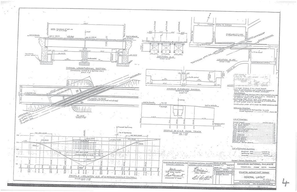
6 IBI Group Scarborough Malvern Light Rail Transit Environmental Assessment Bridge Review Table of Contents 1. INTRODUCTION EXISTING CONDITIONS STRUCTURE GEOMETRY STRUCTURAL ASSESSMENT MISCELLANEOUS STRUCTURAL DETAILS List of Figures Error! No table of figures entries found. Appendices A. General Arrangement Drawing Existing Structures B. Photographs Existing Structures C. Proposed General arrangement Drawings D. Structural Assessment of Highway Morningside Avenue Underpass E. Structural Assessment of Eglinton Avenue CNR Overhead Structure (Uxbridge Subdivision Mile 59.40) 1. INTRODUCTION AECOM was retained by IBI Group to investigate and confirm the feasibility of implementing a Light Rapid Transit (LRT) right-of-way (ROW) on the existing bridges located along the preferred alignment for Scarborough Malvern line, specifically addressing the structural adequacy of the structure, as well as long term maintenance and operational requirements. The intent is upon confirmation of the feasibility of the LRT ROW implementation on the structure, to obtain approval from federal, municipal and railway authorities during the environmental assessment phase in order to move forward with the project. It is recognized that that there are various design and contractual arrangements to be addressed in the subsequent project phases, and the TTC is committed to working with the authorities on these issues. The preferred alignment (see Figure 1) is from Eglinton-Kennedy Station to Kingston Road; Kingston Road- Eglinton Avenue to Morningside Avenue; Morningside Avenue-Kingston Road to Sheppard Avenue; Neilson Road-Sheppard Avenue to Malvern Town. This alignment involves 4 overpass structures and one Subway structure as listed below: Eglinton Avenue CNR Overpass Eglinton Avenue East CNR Subway Kingston Road CNR Overpass Morningside Avenue over Highland Creek Morningside Avenue over Highway 401 Wrap up report 18FEB09.doc Wrap up report 18FEB09.doc/23/02/

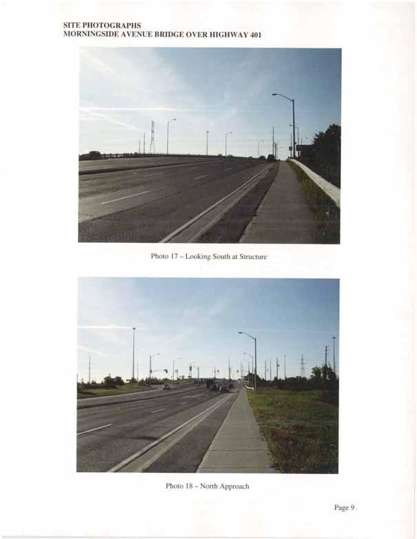
7 3IBI Group Scarborough Malvern Light Rail Transit Environmental Assessment Bridge Review 2. EXISTING CONDITIONS IBI Group Scarborough Malvern Light Rail Transit Environmental Assessment Bridge Review The General Arrangement drawing of the existing structures are presented in Appendix A. A site visit was undertaken by AECOM to confirm the existing structural arrangements and photographs were taken which are presented in Appendix B for records. List of photographs: Eglinton Avenue East CNR subway (at Bellamy) SITE Picture 1: East Elevation Picture 2: West Elevation Picture 3: East Approach Picture 4: West approach Kingston Road CNR Overhead SITE Picture 5: Looking North at the structure Picture 6: South approach Picture 7: Looking South at the structure Picture 8: North approach Morningside Avenue over Highland Creek SITE SITE SITE Picture 9: East Elevation Picture 10: West Elevation Picture 11: Looking South at structure Picture 12: Northapproach Picture 13: Looking North at structure Picture 14: Southapproach Wrap up report 18FEB09.doc/23/02/2009 Wrap up report 18FEB09.doc/23/02/2009 Figure 1 Preferred Alignment and Structure Locations Morningside Avenue over Highway 401 Picture 15: East Elevation Picture 16: West Elevation Picture 17: Looking South at structure Picture 18: Northapproach Picture 19: Looking North at structure Picture 20: Southapproach Wrap up report 18FEB09.doc/23/02/
 1. Eglinton Avenue CNR Overhead (Uxbridge Subdivision, Mile.")
8 4IBI Group Scarborough Malvern Light Rail Transit Environmental Assessment Bridge Review 3. STRUCTURE GEOMETRY The proposed general arrangement drawings are presented in Appendix C and are summarized in Table 1 (on following page) 1. Eglinton Avenue CNR Overhead (Uxbridge Subdivision, Mile ) Width of the bridge deck from gutter to gutter is m, including a 1.220m median, which is a part of the bridge deck structure. There are 3 lanes in each direction. The maximum longitudinal slope of the bridge is 5.2%, is more than assumed maximum slope of 5 % for the new LRT Vehicle. IBI Group Scarborough Malvern Light Rail Transit Environmental Assessment Bridge Review The existing bridge can accommodate the required horizontal clearance for the 2 lanes of traffic eachway and the new LRT designated right-of-way configuration without widening. 2. Eglinton Avenue - CNR Subway at Bellamy (Oshawa Subdivision, Mile ) The width of the roadway under the bridge from gutter to gutter is approximately m, including a 2.438m median. There is 1.524m wide pier column located within the median. There are 3 lanes in each direction. The maximum longitudinal slope of Eglinton Avenue below the bridge structure is 5%, which satisfies the assumed maximum slope of 5% for the new LRT Vehicle. The existing bridge can accommodate the required horizontal clearance for the 2 lanes of traffic each way and the new LRT designated right-of-way configuration. 3. Kingston Road CNR Overhead (Kingston Subdivision, Mile ) Width of the bridge deck from gutter to gutter is m including a 1.530m median. There are 3 lanes in each direction. The maximum longitudinal slope of the bridge is 4.9%, which satisfies the assumed maximum slope of 5% for the new LRT Vehicle. The existing bridge can accommodate the required horizontal clearance for the 2 lanes of traffic eachway and the new LRT designated right-of-way configuration. Wrap up report 18FEB09.doc/23/02/2009 Wrap up report 18FEB09.doc/23/02/ Morningside Avenue over Highland Creek Width of the bridge deck from gutter to gutter is m. There is no median. There are 2 lanes in each direction. The maximum longitudinal slope of the bridge is 5%, which satisfies the assumed maximum slope of 5% for the new LRT Vehicle. The existing bridge cannot accommodate the required horizontal clearance for the 2 lanes of traffic each way and the new LRT designated right-of-way configuration. The structure is needed to be widened and a east side widening is preferred for as the west side has more environmental constraints Wrap up report 18FEB09.doc/23/02/
9 6IBI Group Scarborough Malvern Light Rail Transit Environmental Assessment Bridge Review 7IBI Group Scarborough Malvern Light Rail Transit Environmental Assessment Bridge Review The existing structure is a 6 span m (approx.) long structure constructed in The superstructure consists of wide cast-in-place (CIP) reinforced concrete deck composite with with 9 precast prestressed concrete girder (CPCI type IV). The superstructure is supported on conventional CIP reinforced concrete piers and abutments. Structure is provided with expansion joints at Pier 3 and North abutment. At present the existing structure carries 2 lanes of north bound traffic and 2 lanes of south bound traffic without median. Raised concrete sidewalks are provided on both the east and west side of the structure. For the structure widening following 5 alternatives were considered: Option 1A LRT right of way (ROW) at the median with east side structure widening. Option 1B LRT ROW at the median with east side structure widening and with bicycle lanes Option 2A LRT ROW on the east side with east side structure widening Option 2B LRT ROW on the east side with east side structure widening and with bicyle lanes Option 2C Separate dedicated structure for the LRT ROW and structure widening to accommodate the bicycle lanes. Due to the environmental concerns on the west side widening on this side was not considered. In our cost comparisons we have not included the cost for track bed construction as it is common to all options. The differences in the cost of approach road works are to be taken in to consideration while deciding on the final choice of the structure. The General Arrangement drawing for the various options are provided in Appendix C OPTION 1A: LRT ROW at median and with bicycle lanes For this alternative, the existing structures would be widened by 7.492m to accommodate the proposed LRT Right of way at the median. This will require additional girders and widening of superstructure, substructure and foundations to support the widened superstructure. Structural system will be similar to the existing structure. Construction will be carried out in 2 stages: Stage 1: Construct the structure widening while maintaining 2 lanes of traffic in both north and south direction on the original structure. Stage 2: Divert the north bound traffic to the new widened structure and construct LRT track bed. This will involve extensive traffic staging works and roadway protection works for the construction of abutments. The estimated cost for this alternative is $5.40 million. OPTION 1B: LRT ROW at median and without bicycle lanes This alternative is similar to Option 1A except for reduced area of deck widening due to the elimination of bicycle lanes. The estimated cost for this alternative is $4.55 million. OPTION 2A: LRT ROW on the east side and with bicycle lanes For this alternative, the existing structures would be widened by m to accommodate the proposed LRT Right of way on the east side. This will require additional girders and widening of superstructure, substructure and foundations to support the widened superstructure. Structural system will be similar to the existing structure. Construction will be carried out in a single stage, while maintaining 2 lanes of traffic in both north and south direction on the original structure. This will involve minimum traffic staging works and roadway protection works for the construction of abutments. The estimated cost for this alternative is $6.25 million. OPTION 2B: LRT ROW on the east side and without bicycle lanes This alternative is similar to Option 2A except for reduced area of deck widening due to the elimination of bicycle lanes. The cost estimate for this alternative is $5.40 million. OPTION 2C: LRT ROW on the east side on separate structure and with addition of bicycle lanes on the original structure The new structure in this option can be constructed without affecting the existing traffic conditions significantly. Minimal traffic staging works and roadway protection works will be required during construction for widening the deck due to addition of bicycle lanes. The cost estimate for this alternative is $6.45 million. Recommendations The least cost alternative is Option 1B, with a value of $4.55 million, which consists of widening the structure on east side with the LRT ROW in the median. This alternative, however does not allow for bicycle lanes. Wrap up report 18FEB09.doc/23/02/ Wrap up report 18FEB09.doc/23/02/
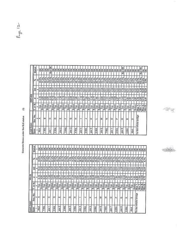
10 8IBI Group Scarborough Malvern Light Rail Transit Environmental Assessment Bridge Review 9IBI Group Scarborough Malvern Light Rail Transit Environmental Assessment Bridge Review If the bicycle lanes are required the least cost alternative will be Option 1A, which consists of widening the structure on east side with the LRT ROW in the median. 5. Morningside Avenue over Highway 401 The width of the roadway under the bridge from gutter to gutter is approximately m There is no median. There are 2 lanes in each direction and also 1 South bound merging lane. The maximum longitudinal slope of the bridge structure is 3.5%, which satisfies the assumed maximum slope of 5% for the new LRT Vehicle. The existing bridge can accommodate the required horizontal clearance for the 2 lanes of traffic eachway and the new LRT designated right-of-way configuration. increase in the range of 5 to 10%, similar to increase in support reactions/ shear forces in the deck, if a conventional concrete trackbed is adopted. It is unlikely that strengthening of the foundations will be required for this additional load, however, underpinning methods are available to strengthen the capacity of existing abutment and pier footings, if necessary. The results of the structural evaluation indicates that if a light-weight polymer infill with a unit weight in the order of 2 to 4 kn/m3 is provided for the track bed, strengthening of superstructure and substructure will not be required. It should be noted that, the TTC are investigating this technique for several bridges in the City of Toronto for the Transit City program. A further option which could be considered would be to fix the rails directly to the concrete deck and eliminate the trackbed, in which case the structure is subjected to loads similar to that of the existing structure. However there are numerous maintenance and durability issues associated with fixing the rails directly to the deck, which could compromise the long term life of the structure, and this alternative is not recommended for further consideration. 4. STRUCTURAL ASSESSMENT A structural assessment has been carried out to determine if the existing bridges can accommodate the proposed LRT loading. The design loads that the existing structure has been evaluated include the following: Dead Loads: The dead loads due to deck, sidewalk, parapet walls with handrails, asphalt wearing surface, and light poles. Live Loads: The original design live loads were based on AASHTO HS 25 load. While investigating the structure for the suitability of carrying the LRT vehicle, we have also investigated for the requirements of the current Canadian Highway Bridge Design Code (CHBDC) CAN/CSA S6-06 and CL-625-ONT Truck load of 625 kn. Other Loads: Other loads that need to be considered in the design of the structure include secondary loads due to posttensioning, thermal, wind, braking etc. as specified in the code. A structural assessment of the existing bridges has been carried for the following load conditions: AASHTO HS25 Truck (where original structure has been designed for this load) CHBDC CAN/CSA - S6-06 CL-625-ONT Truck Proposed LRT Live load and additional loads due to conventional trackbed & accessories Proposed LRT Live load and additional loads due to lightweight trackbed & accessories The results of the structural evaluation are summarized in Table 2 (at the end of this Section). The table indicates the increase in bending moment and shear forces due to LRT and track bed loads over the current design live loads under service load limit states (SLS). The loads acting on substructure and foundation are expected to Wrap up report 18FEB09.doc/23/02/ Wrap up report 18FEB09.doc/23/02/

11 10IBI Group Scarborough Malvern Light Rail Transit Environmental Assessment Bridge Review 11IBI Group Scarborough Malvern Light Rail Transit Environmental Assessment Bridge Review 5. MISCELLANEOUS STRUCTURAL DETAILS There are a number of details associated with the LRT ROW which will require modification of the existing structure, and which will need to be detailed during the design phases of the project. A preliminary assessment of the impact of the LRT ROW on the structure has been carried out, and the following items will need to be addressed: Poles will be required on the deck to provide overhead power for the LRT. The forces due to poles supporting the catenaries will induce primarily localized effects. Pedestals and connections to deck slab will need to be provided and detailed appropriately. Expansion joints will need to be provided to minimize the effect of movement of the structure on the continuous welded rail. Expansion can be accommodated through combinations of rail anchors and bolted joints allowing for limited movements or special proprietary rail expansion joints. Protection of the structures and its components from corrosion due to stray currents should be provided by appropriate method of grounding or coating of reinforcement or insulating with a membrane below the trackbed. Proper detailing of waterproofing and paving where it abuts the LRT trackbed will be required to maintain the long term durability of the deck. The existing structure does not have deck drains. As the existing roadway is on a symmetrical crest curve, deck drains could be provided if necessary on the bridge structure, to provide adequate drainage of the LRT right-of-way. The above identified miscellaneous structural details can be addressed with standard techniques that have been adopted elsewhere, and will be fully investigated during the preliminary and detail design phases of the project. The TTC is committed to working with City of Toronto and other authorities on these issues. Table 2 Long term maintenance and rehabilitation of the bridge deck and the LRT trackbed will be somewhat complicated by the LRT right-of-way. There are a number of alternatives available, with the simplest being that a temporary closure of the LRT ROW will be required during major rehabilitative works on the bridge, which extend for 4 to 6 months in duration, and local bus service be utilized. Alternatives and details will be developed in subsequent project phases. Wrap up report 18FEB09.doc/23/02/ Wrap up report 18FEB09.doc/23/02/
12
13 Appendix A General Arrangement Drawings Existing Structure (title pages.doc)
14
15
16
17
18
19
20
21 Appendix B Photographs Existing Structures (title pages.doc)
22
23
24
25
26
27 Appendix C Proposed General Arrangement Drawings (title pages.doc)
28
29
30
31
32
33
34
35
36
37 Appendix D Structural Assessment of Highway Morningside Avenue Underpass (title pages.doc)
38 IBI GROUP STRUCTURAL ASSESSMENT OF THE HIGHWAY 401 MORNINGSIDE AVENUE UNDERPASS STRUCTURE FOR LIGHT RAPID TRANSIT FINAL Prepared by: Totten Sims Hubicki Associates (1997) Limited doing business as AECOM 300 Water Street, Whitby, ON, Canada L1N 9J2 T F Date: December 2008 Structure Assessment Report 12DEC08.doc
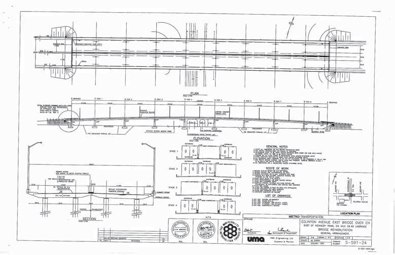
39 Executive Summary AECOM was retained by IBI Group to investigate and confirm the feasibility of implementing a Light Rapid Transit (LRT) right-of-way (ROW) on the Morningside Avenue structure over Highway 401, specifically addressing the structural adequacy of the underpass structure, as well as long term maintenance and operational requirements. The intent is upon confirmation of the feasibility of the LRT ROW implementation on the structure, to obtain approval from the MTO during the environmental assessment phase in order to move forward with the project. It is recognized that that there are various design and contractual arrangements to be addressed in the subsequent project phases, and the TTC is committed to working with the MTO on these issues. It is our understanding that this structure was designed to accommodate an ultimate 6-lane configuration for the Morningside Avenue, and in the interim provide tapers on the south approach to pick-up and lose a lane, and on the north approach have the additional lane develop and end at the intersection as a ramp lane and must right turn lane respectively. An assessment of the existing Highway 401 Morningside Avenue underpass structure has been carried out to determine if it can accommodate the proposed Scarborough - Malvern LRT designated ROW, including two lanes of traffic in each direction. The findings indicate that the new LRT ROW and two traffic lanes can be accommodated on the existing structure without a need for deck widening. A detailed structural evaluation was also undertaken to investigate effects of additional loads due to LRT and its accessories. The comparison between the CL-625-ONT truck load and the assumed new LRT vehicle load shows that these loads are almost same. There is additional load on the bridge due to the weight of the LRT trackbed. It is observed that a conventional reinforced concrete track bed will require strengthening of the steel girders. The strengthening is required in the negative bending moment zones over the piers which could be undertaken by strengthening the compression flanges with additional plates. Alternatively if the trackbed load is reduced by use of light weight materials, the structure will be subjected to load effects similar or less than that due to current CHBDC loading conditions. There are a number of operational and maintenance features which will need to be accommodated for the new LRT, including the provision of poles on the deck to power the trains, modifications to the waterproofing and paving on the deck to accommodate the track bed, provision for drainage, provision for expansions joints in the continuous rail. These considerations have been identified, and a number of standard techniques that have been adopted elsewhere are available for investigation during the preliminary and detail design phases of the project. Our findings indicate that it is feasible to accommodate the proposed LRT right-of-way on the Highway Morningside Avenue underpass structure, without a need for deck widening. The girders could be strengthened to accommodate the additional load from a conventional concrete bed, or alternatively a light weight material track bed could be considered. Structure Assessment Report 12DEC08.doc - i -

40 IBI Group Structural Assessment for the Highway Morningside Avenue Underpass Structure for Light Rapid Transit Table of Contents 1. LOCATION EXISTING STRUCTURE LOCATION The underpass structure is located along Morningside Avenue where it intersects with Highway 401 as shown on the following Key Plan. 3. EXISTING CROSS SECTION STRUCTURE GEOMETRY STRUCTURAL ASSESSMENT MISCELLANEOUS STRUCTURAL DETAILS... 4 List of Figures Figure 1. Key Plan...1 Appendices A. General Arrangement Drawing Existing Structure B. General Arrangement Drawing - Proposed Deck Cross Section with LRT Tracks C. Details of Structural Evaluation SITE Figure 1. Key Plan Structure Assessment Report 12DEC08.doc Structure Assessment Report 12DEC08.doc/15/12/
41 IBI Group Structural Assessment for the Highway Morningside Avenue Underpass Structure for Light Rapid Transit IBI Group Structural Assessment for the Highway Morningside Avenue Underpass Structure for Light Rapid Transit 2. EXISTING STRUCTURE The maximum longitudinal slope of the bridge structure is 3.5%, which satisfies the assumed maximum slope of 5% for the new LRT Vehicle. The existing structure, which was constructed in about 1988, is a m long three span (40.0m, 57.35m, 36.0m) structural steel trapezoidal box girder bridge with a 225 mm thick cast-in-place concrete deck and 90mm thick waterproofing and asphalt wearing surface. The bridge superstructure is supported on cast-in-place reinforced concrete abutments and piers founded on footings and constructed at normal to the road alignment. The General Arrangement drawing of the existing structure is provided in Appendix A. 3. EXISTING CROSS SECTION The cross section of the existing structure consists of the following: East Barrier wall m Sidewalk m Ramp Lane Varies Traffic Lanes 3 x 3.500m Median m Traffic Lanes 3 x 3.500m Ramp Lane Varies Sidewalk m West Barrier wall m 4. STRUCTURE GEOMETRY It is our understanding that the Highway 401 Morningside Underpass structure was originally designed to accommodate an ultimate 6-lane configuration for Morningside Avenue, and in the interim provided tapers on the south approach to pick-up and lose a lane, and on the north approach have the additional lane develop and end at the intersection as a ramp lane and must right turn lane respectively. A preliminary assessment of the existing bridge geometry has been carried out, indicating the following: The width of the roadway at the bridge from gutter to gutter is approximately 31.0 m, which includes a 1.20 m wide median. The bridge can accommodate the required horizontal clearance for the 2 lanes of traffic in each and the new LRT designated right-of-way configuration. It is feasible to implement the LRT right-of-way geometrically. There are 2 lanes and an auxiliary lane in each direction (as previously mentioned, the additional lane in each direction was constructed to be consistent with the then planned ultimate 6-lane cross-section for Morningside Avenue. A preliminary general arrangement drawing showing the proposed LRT configuration on the Morningside Underpass structure is provided in Appendix B. 5. STRUCTURAL ASSESSMENT The design loads that the existing structure has been designed to include the following: Dead Loads: The dead loads due to girder, deck, sidewalk, barrier walls, asphalt wearing surface, and light poles Live Loads: The original design live loads were based on Ontario Highway Bridge Design Code, While investigating the structure for the suitability of carrying the LRT vehicle, we have considered the requirements of the current Canadian Highway Bridge Design Code (CHBDC) CAN/CSA S6-06. It is noted that the Gross load due to OHBD Truck was 700 kn, compared to the CHBDC CL-625-ONT Truck load of 625 kn. While the overall truck load has decreased in the most recent code, the new live load factor is higher than that specified in the OHBDC Other Loads: Other loads that need to be considered in the design of the structure include thermal, wind, braking etc. as specified in the code. A structural assessment of the existing bridge has been carried for the following load conditions: CHBDC CAN/CSA - S6-06 CL-625-ONT Truck Proposed LRT Live load and additional loads due to conventional trackbed & accessories Proposed LRT Live load and additional loads due to lightweight trackbed & accessories The results of the structural evaluation are summarized in Appendix C, and indicate that the superstructure will require strengthening if a conventional concrete trackbed is provided for the LRT. The results indicate the ultimate limit state (ULS) moments under LRT loading with a conventional concrete trackbed increase by approximately 15% in comparison with CHBDC loading for which the existing structures have been designed. The extent of overloading for the structure is summarized in Table 1. The loads acting on substructure and foundation would be expected to increase by significantly less then this amount, in the range of 5 to 10%, if conventional concrete trackbed is adopted. It is unlikely that strengthening of the foundations will be required for this additional load, however, underpinning methods are available to strengthen the capacity of existing abutment and pier footings, if necessary. The results of the structural evaluation indicates that if a light-weight polymer infill with a unit weight in the order of 2 to 4 kn/m3 is provided for the trackbed, strengthening of superstructure and substructure strengthening will not Structure Assessment Report 12DEC08.doc/15/12/ Structure Assessment Report 12DEC08.doc/15/12/
42 IBI Group Structural Assessment for the Highway Morningside Avenue Underpass Structure for Light Rapid Transit IBI Group Structural Assessment for the Highway Morningside Avenue Underpass Structure for Light Rapid Transit be required. It should be noted that, the TTC are investigating this technique for several bridges in the City of Toronto for the Transit City program. The maximum longitudinal slope of the bridge structure is 3.5%, which satisfies the assumed maximum slope of 5% for the new LRT Vehicle. A further option which could be considered would be to fix the rails directly to the concrete deck and eliminate the trackbed, in which case the structure is subjected to loads similar to that of the existing structure. However there are numerous maintenance and durability issues associated with fixing the rails directly to the deck, which could compromise the long term life of the structure, and this alternative is not recommended for further consideration. 6. MISCELLANEOUS STRUCTURAL DETAILS There are a number of details associated with the LRT ROW which will require modification of the existing structure, and which will need to be detailed during the design phases of the project. A preliminary assessment of the impact of the LRT ROW on the structure has been carried out, and the following items will need to be addressed: Poles will be required on the deck to provide overhead power for the LRT. The forces due to poles supporting the catenaries and light poles will induce primarily localized effects. Pedestals and connections to deck slab will need to be provided and detailed appropriately. Expansion joints will need to be provided to minimize the effect of movement of the structure on the continuous welded rail. Expansion can be accommodated through combinations of rail anchors and bolted joints allowing for limited movements or special proprietary rail expansion joints. Ensure protection of structures and components from corrosion due to stray currents by appropriate method of grounding or coating reinforcements or insulating with a membrane below the trackbed. Proper detailing of waterproofing and paving where it abuts the LRT trackbed will be required to maintain the long term durability of the deck. As the existing roadway is on a symmetrical crest curve and the structure is approximately 134.2m long this structure does not require deck drains. However adequate drainage of the LRT right-of-way drainage will need to be addressed. Long term maintenance and rehabilitation of the bridge deck and the LRT trackbed will be somewhat complicated by the LRT right-of-way. There are a number of alternatives available, with the simplest being that a temporary closure of the LRT ROW will be required during major rehabilitative works on the bridge, which extend for 4 to 6 months in duration, and local bus service be utilized. Alternatives and details will be developed in subsequent project phases. The above identified miscellaneous structural details can be addressed with standard techniques that have been adopted elsewhere, and will be fully investigated during the preliminary and detail design phases of the project. The TTC is committed to working with the MTO on these issues. A preliminary general arrangement drawing showing the proposed LRT configuration on the Morningside Underpass structure is provided in Appendix B. 5. STRUCTURAL ASSESSMENT The design loads that the existing structure has been designed to include the following: Dead Loads: The dead loads due to girder, deck, sidewalk, barrier walls, asphalt wearing surface, and light poles Live Loads: The original design live loads were based on Ontario Highway Bridge Design Code, While investigating the structure for the suitability of carrying the LRT vehicle, we have considered the requirements of the current Canadian Highway Bridge Design Code (CHBDC) CAN/CSA S6-06. It is noted that the Gross load due to OHBD Truck was 700 kn, compared to the CHBDC CL-625-ONT Truck load of 625 kn. While the overall truck load has decreased in the most recent code, the new live load factor is higher than that specified in the OHBDC Other Loads: Other loads that need to be considered in the design of the structure include thermal, wind, braking etc. as specified in the code. A structural assessment of the existing bridge has been carried for the following load conditions: CHBDC CAN/CSA - S6-06 CL-625-ONT Truck Proposed LRT Live load and additional loads due to conventional trackbed & accessories Proposed LRT Live load and additional loads due to lightweight trackbed & accessories The results of the structural evaluation are summarized in Appendix C, and indicate that the superstructure will require strengthening if a conventional concrete trackbed is provided for the LRT. The results indicate the ultimate limit state (ULS) moments under LRT loading with a conventional concrete trackbed increase by approximately 15% in comparison with CHBDC loading for which the existing structures have been designed. The extent of overloading for the structure is summarized in Table 1. The loads acting on substructure and foundation would be expected to increase by significantly less then this amount, in the range of 5 to 10%, if conventional concrete trackbed is adopted. It is unlikely that strengthening of the foundations will be required for this additional load, however, underpinning methods are available to strengthen the capacity of existing abutment and pier footings, if necessary. The results of the structural evaluation indicates that if a light-weight polymer infill with a unit weight in the order of 2 to 4 kn/m3 is provided for the trackbed, strengthening of superstructure and substructure strengthening will not Structure Assessment Report 12DEC08.doc/15/12/ Structure Assessment Report 12DEC08.doc/12/12/
43 IBI Group Structural Assessment for the Highway Morningside Avenue Underpass Structure for Light Rapid Transit be required. To be noted, the TTC are investigating this technique for several bridges in the City of Toronto for the Transit City program. A further option which could be considered would be to fix the rails directly to the concrete deck, in which case the structure is subjected to loads similar to that of the existing structure. However there are numerous maintenance and durability issues associated with fixing the rails directly to the deck, which could compromise the long term life of the structure, and this alternative is not recommended for further consideration. 6. MISCELLANEOUS STRUCTURAL DETAILS There are a number of details associated with the LRT ROW which will require modification of the existing structure, and which will need to be detailed during the design phases of the project. A preliminary assessment of the impact of the LRT ROW on the structure has been carried out, and the following items will need to be addressed: Poles will be required on the deck to provide overhead power for the LRT. The forces due to poles supporting the catenaries and light poles will induce primarily localized effects and pedestals and connections to deck slab will need to be provided and detailed appropriately. Expansion joints will need to be provided to minimize the effect of movement of the structure on continuous welded rail. Expansion can be accommodated through combinations of rail anchors and bolted joints allowing for limited movements or special proprietary rail expansion joints. Ensure protection of structures and components from corrosion due to stray currents by appropriate method of grounding or coating reinforcements or insulating with a membrane below the trackbed. Proper detailing of waterproofing and paving where it abuts the LRT trackbed will be required to maintain the long term durability of the deck. As the existing roadway is on a symmetrical crest curve and the structure is approximately 134.2m long this structure does not require deck drains. However adequate drainage of the LRT right-of-way drainage will need to be addressed. Long term maintenance and rehabilitation of the bridge deck and the LRT trackbed will be somewhat complicated by the LRT right-of-way. There are a number of alternatives available, with the simplest being that a temporary closure of the LRT ROW will be required during major rehabilitative works on the bridge, which extend for 4 to 6 months in duration, and local bus service be utilized. Alternatives and details will be developed in subsequent project phases. The above identified miscellaneous structural details can be addressed with standard techniques that have been adopted elsewhere, and will be fully investigated during the preliminary and detail design phases of the project. The TTC is committed to working with the MTO on these issues. Structure Assessment Report 12DEC08.doc/12/12/

44 Appendix A General Arrangement Drawing Existing Structure (file code)
45 Appendix B General Arrangement Drawing Proposed Deck Cross Section with LRT Tracks (file code)
46 Appendix C Details of Structural Evaluation (file code)
47
48
49
50
51
52
53
54
55
56
57 Appendix E Structural Assessment of Eglinton Avenue CNR Overhead Structure (Uxbridge Subdivision Mile 59.40) (title pages.doc)
58 IBI Group Structural Assessment of Highway 401 Morningside Avenue Structure forlrt Loads Statement of Qualifications and Limitations IBI GROUP STRUCTURAL ASSESSMENT OF EGLINTON AVENUE CNR OVERHEAD STRUCTURE UXBRIDGE SUBDIVISION MILE FOR LIGHT RAPID TRANSIT Draft 2008 Totten Sims Hubicki Associates (1997) Limited ALL RIGHTS RESERVED THIS DOCUMENT IS PROTECTED BY COPYRIGHT AND TRADE SECRET LAW AND MAY NOT BE REPRODUCED IN ANY MANNER, OR FOR ANY PURPOSE, EXCEPT BY WRITTEN PERMISSION OF Totten Sims Hubicki Associates (1997) Limited." The attached Report (the Report ) has been prepared by Totten Sims Hubicki Associates (1997) Limited doing business as AECOM ( AECOM ) for the benefit of Ministry of transportation, Central Region ( Client ) in accordance with the agreement between AECOM and Client (the Agreement ). The information, data, recommendations and conclusions contained in the Report: Prepared by: Totten Sims Hubicki Associates (1997) Limited doing business as AECOM 300 Water Street, Whitby, ON, Canada L1N 9J2 T F are subject to the budgetary, time and other constraints and limitations in the Agreement and the qualifications contained in the Report (the Limitations ) represent AECOM s professional judgement in light of the Limitations and industry standards for the preparation of similar reports may be based on information provided to AECOM which has not been independently verified have not been updated must be read as a whole and sections thereof should not be read out of such context Date: December 2008 were prepared for the specific purposes described in the Report and the Agreement and must not be used for any other purpose whatsoever Unless expressly stated to the contrary in the Report or the Agreement, AECOM: shall not be responsible for any events or circumstances that may have occurred since the date on which the Report was prepared or for any inaccuracies contained in information that was provided to AECOM makes no guarantees or warranties whatsoever, whether express or implied, with respect to the Report or any part thereof, other than that the Report represents AECOM s professional judgement as described above shall not be deemed to have represented that the Report or any part thereof is exhaustive or applicable to any specific use other than that described in the Report and the Agreement Except as required by law or otherwise agreed by AECOM and Client, the Report: is to be treated as confidential may not be used or relied upon by third parties Except as described above, AECOM denies any liability in respect of the Report or parts thereof and shall not be responsible for any damages arising from use of the Report or parts thereof. This Disclaimer is attached to and forms part of the Report. THIS DOCUMENTATION IS SUPPLIED TO MTO-Central Region BY AECOM AND CONSTITUTES CONFIDENTIAL TRADE SECRETS, OR COMMERCIAL, FINANCIAL, SCIENTIFIC, OR TECHNICAL INFORMATION. THIS DOCUMENTATION IS SUBMITTED TO MTO-Central Region IN CONFIDENCE. IT HAS SIGNIFICANT ECONOMIC VALUE TO AECOM AND ITS DISCLOSURE, WITHOUT THE EXPRESS CONSENT OF AECOM, COULD REASONABLY BE EXPECTED TO LEAD TO SIGNIFICANT AND UNDUE FINANCIAL AND OTHER HARM TO AECOM, INCLUDING HARM TO AECOM'S COMPETITIVE AND NEGOTIATING POSITIONS, AND UNDUE FINANCIAL GAIN TO ONE OR MORE THIRD PARTIES. Kennedy Structure Assessment 15DEC08.doc Kennedy Structure Assessment 15DEC08.doc
59 Revision Log December 15, 2008 Project Number: Revision # Revised By Date Issue / Revision Description Mr. Harold Sich Associate IBI Group 230 Richmond Street, 5 th Floor Toronto, Ontario M5V 1V6 Dear Harold: Re: STRUCTURAL ASSESSMENT OF EGLINTON AVENUE CNR OVERHEAD STRUCTURE UXBRIDGE SUBDIVISION MILE FOR LIGHT RAPID TRANSIT We are enclosing herewith two (2) copies of our structural assessment report as noted above. Please advise if we could be of further assistance in the above regards. Sincerely, Totten Sims Hubicki Associates (1997) Limited doing business as AECOM David LeBlanc, M.Eng., P.Eng. Head, Structures Department david.leblanc@aecom.com DL:smb Encl. cc: File Kennedy Structure Assessment 15DEC08.doc17/12/2008 Kennedy Structure Assessment 15DEC08.doc17/12/2008
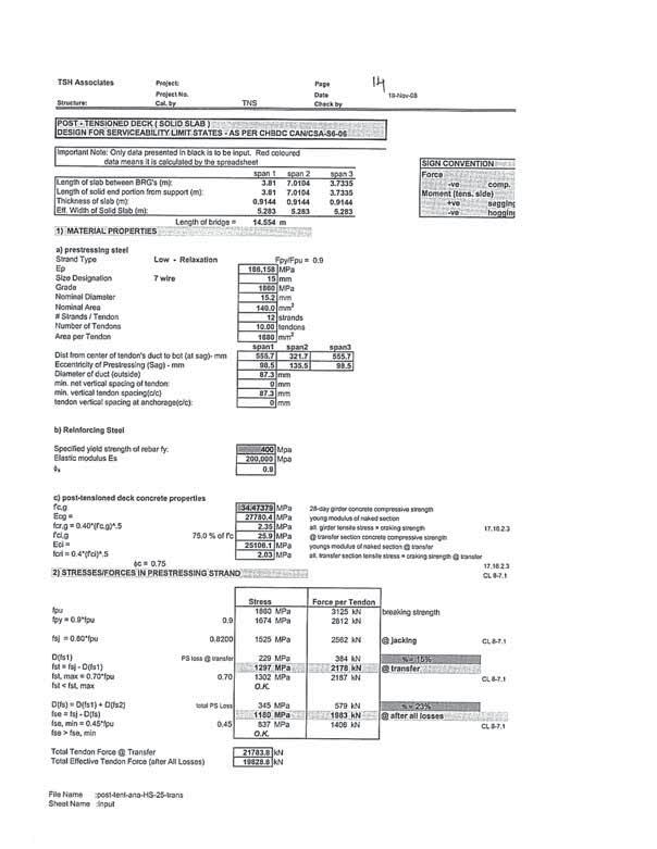
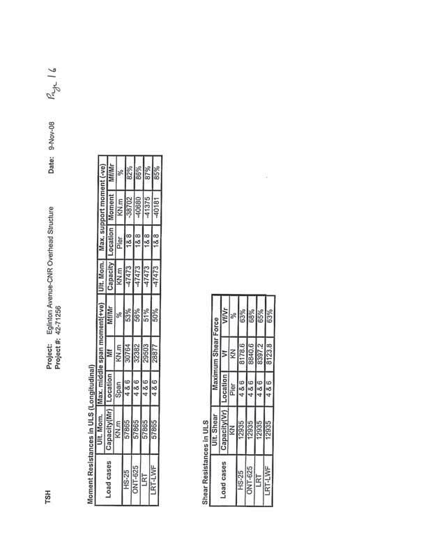
60 Signature Page Executive Summary Report Prepared By: Report Reviewed By: AECOM was retained by IBI Group to investigate and confirm the feasibility of implementing a Light Rapid Transit (LRT) right-of-way (ROW) on the Eglinton Avenue CNR Overhead structure, Uxbridge Subdivision Mile 59.40, at Kennedy Road, specifically addressing the structural adequacy of the overhead structure, as well as long term maintenance and operational requirements. The intent is upon confirmation of the feasibility of the LRT ROW implementation on the structure, to obtain approval from City of Toronto and Canadian National Railway during the environmental assessment phase in order to move forward with the project. It is recognized that that there are various design and contractual arrangements to be addressed in the subsequent project phases, and the TTC is committed to working with the authorities on these issues. Selva Balasundaram, P.Eng., Senior Structural Engineer David LeBlanc, M.Eng., P.Eng., Head, Structural Department Existing structure is a m (approx.) long 9 span (21.34m + 7 x 27.43m m) post-tensioned concrete twin structures constructed in At present the existing structure carries 3 lanes of east bound lanes and 3 lanes of west bound lanes with a raised concrete median and sidewalks at both north and south side of the structure. The existing structure has been rehabilitated in An assessment of the existing Eglinton Avenue CNR Overhead structure has been carried out to determine if it can accommodate the proposed Scarborough - Malvern LRT designated ROW, including two lanes of traffic in each direction. The findings indicate that the new LRT ROW and two traffic lanes can be accommodated on the existing structure without a need for deck widening. A detailed structural evaluation was also undertaken to investigate effects of additional loads due to LRT and its accessories. Existing structure has been designed for AASHTO HS 25 live load. Our evaluation indicates that the structure is overstressed under service limit state (SLS) for both CL-625-ONT truck load and LRT live loads with conventional reinforced concrete track bed. Structural capacity is adequate under ultimate limit states (ULS) for both CL-625-ONT truck load and LRT live loads. Alternatively if the trackbed load is reduced by use of light weight materials, the structure will be subjected to load effects within the permissible limits at both SLS and ULS limit states. There are a number of operational and maintenance features which will need to be accommodated for the new LRT, including the provision of poles on the deck to power the trains, modifications to the waterproofing and paving on the deck to accommodate the track bed, provision for drainage, provision for expansions joints in the continuous rail. These considerations have been identified, and a number of standard techniques that have been adopted elsewhere are available for investigation during the preliminary and detail design phases of the project. Our findings indicate that it is feasible to accommodate the proposed LRT right-of-way on the Eglinton Avenue CNR Overhead structure, without a need for deck widening. The structure has adequate capacity to withstand LRT loads in conjunction with the use of a light weight material for the track bed. Kennedy Structure Assessment 15DEC08.doc17/12/2008 Kennedy Structure Assessment 15DEC08.doc - i -

61 IBI Group Structural Assessment for the Highway Morningside Avenue Underpass Structure for Light Rapid Transit Table of Contents 1. LOCATION EXISTING STRUCTURE EXISTING CROSS SECTION LOCATION The overhead structure is located at the intersection of Eglinton Avenue East and CN Rail tracks, at mileage Uxbridge Subdivision, near Kennedy Road as shown on the following Key Plan. Eglinton Avenue East is under the jurisdiction of City of Toronto. 4. STRUCTURE GEOMETRY STRUCTURAL ASSESSMENT MISCELLANEOUS STRUCTURAL DETAILS... 4 List of Figures Figure 1. Key Plan...1 SITE Appendices A. General Arrangement Drawing Existing Structure B. General Arrangement Drawing - Proposed Deck Cross Section with LRT Tracks C. Details of Structural Evaluation Figure 1. Key Plan Kennedy Structure Assessment 15DEC08.doc Kennedy Structure Assessment 15DEC08.doc/17/12/
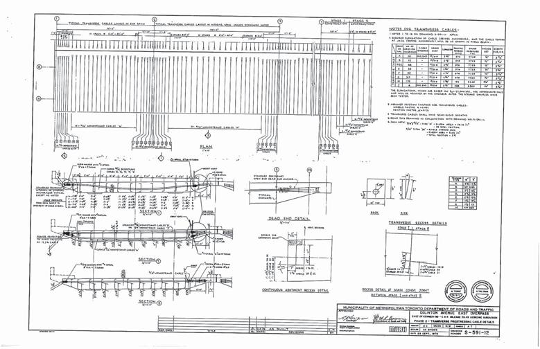
62 IBI Group Structural Assessment for the Highway Morningside Avenue Underpass Structure for Light Rapid Transit IBI Group Structural Assessment for the Highway Morningside Avenue Underpass Structure for Light Rapid Transit 2. EXISTING STRUCTURE The existing structure, which was constructed in about 1979, is a m long nine span (21.33m, 7 x 27.43m, 21.33m) post-tensioned concrete structure with 90mm thick waterproofing and asphalt wearing surface. The bridge superstructure is supported on cast-in-place reinforced concrete abutments and piers founded on footings and constructed at normal to the road alignment. The General Arrangement drawing of the existing structure and post-tensioning details are presented in Appendix A. 3. EXISTING CROSS SECTION The cross section of the existing structure consists of the following: North parapet wall m Sidewalk m Side clearance m Traffic Lanes 3 x 3.500m Median m Traffic Lanes 3 x 3.500m Side clearance m Sidewalk m West Barrier wall m 4. STRUCTURE GEOMETRY A preliminary assessment of the existing bridge geometry has been carried out, indicating the following: The width of the roadway at the bridge from gutter to gutter is approximately m, which includes a 1.20 m wide median. The bridge can accommodate the required horizontal clearance for the 2 lanes of traffic in each and the new LRT designated right-of-way configuration. It is feasible to implement the LRT right-of-way geometrically. The maximum longitudinal slope of the bridge structure is 5.2%, which is marginally more than the assumed maximum slope of 5% for the new LRT Vehicle. A preliminary general arrangement drawing showing the proposed LRT configuration on the Morningside Underpass structure is provided in Appendix B. 5. STRUCTURAL ASSESSMENT The design loads that the existing structure has been designed to include the following: Dead Loads: The dead loads due to deck, sidewalk, parapet walls with handrails, asphalt wearing surface, and light poles Live Loads: The original design live loads were based on AASHTO HS 25 load. While investigating the structure for the suitability of carrying the LRT vehicle, we have also investigated for the requirements of the current Canadian Highway Bridge Design Code (CHBDC) CAN/CSA S6-06 and CL-625-ONT Truck load of 625 kn. Other Loads: Other loads that need to be considered in the design of the structure include secondary loads due to posttensioning, thermal, wind, braking etc. as specified in the code. A structural assessment of the existing bridge has been carried for the following load conditions: AASHTO HS25 Truck CHBDC CAN/CSA - S6-06 CL-625-ONT Truck Proposed LRT Live load and additional loads due to conventional trackbed & accessories Proposed LRT Live load and additional loads due to lightweight trackbed & accessories The results of the structural evaluation are summarized in Appendix C, and indicate that the superstructure is overstressed under service limit states (SLS) by about 3% for CHBDC CL-625-ONT Truck load and about 18% for LRT loads with conventional reinforced concrete trackbed. The structure has adequate capacity under ultimate limit states (ULS) for the various loading conditions considered. The loads acting on substructure and foundation are expected to increase in the range of 5 to 10%, similar to increase in support reactions/ shear forces in the deck, if conventional concrete trackbed is adopted. It is unlikely that strengthening of the foundations will be required for this additional load, however, underpinning methods are available to strengthen the capacity of existing abutment and pier footings, if necessary. The results of the structural evaluation indicates that if a light-weight polymer infill with a unit weight in the order of 2 to 4 kn/m3 is provided for the trackbed, strengthening of superstructure and substructure strengthening will not be required. It should be noted that, the TTC are investigating this technique for several bridges in the City of Toronto for the Transit City program. A further option which could be considered would be to fix the rails directly to the concrete deck and eliminate the trackbed, in which case the structure is subjected to loads similar to that of the existing structure. However there are numerous maintenance and durability issues associated with fixing the rails directly to the deck, which could compromise the long term life of the structure, and this alternative is not recommended for further consideration. Kennedy Structure Assessment 15DEC08.doc/17/12/ Kennedy Structure Assessment 15DEC08.doc/17/12/
63 IBI Group Structural Assessment for the Highway Morningside Avenue Underpass Structure for Light Rapid Transit 6. MISCELLANEOUS STRUCTURAL DETAILS There are a number of details associated with the LRT ROW which will require modification of the existing structure, and which will need to be detailed during the design phases of the project. A preliminary assessment of the impact of the LRT ROW on the structure has been carried out, and the following items will need to be addressed: Appendix A General Arrangement Drawing Existing Structure Poles will be required on the deck to provide overhead power for the LRT. The forces due to poles supporting the catenaries and light poles will induce primarily localized effects. Pedestals and connections to deck slab will need to be provided and detailed appropriately. Expansion joints will need to be provided to minimize the effect of movement of the structure on the continuous welded rail. Expansion can be accommodated through combinations of rail anchors and bolted joints allowing for limited movements or special proprietary rail expansion joints. Ensure protection of structures and components from corrosion due to stray currents by appropriate method of grounding or coating reinforcements or insulating with a membrane below the trackbed. Proper detailing of waterproofing and paving where it abuts the LRT trackbed will be required to maintain the long term durability of the deck. Existing structure is not provided with any deck drains. As the existing roadway is on a symmetrical crest curve deck drains could be avoided on the bridge structure although the length of the structure approximately m is more than 120m. However adequate drainage of the LRT right-of-way drainage will need to be addressed. Long term maintenance and rehabilitation of the bridge deck and the LRT trackbed will be somewhat complicated by the LRT right-of-way. There are a number of alternatives available, with the simplest being that a temporary closure of the LRT ROW will be required during major rehabilitative works on the bridge, which extend for 4 to 6 months in duration, and local bus service be utilized. Alternatives and details will be developed in subsequent project phases. The above identified miscellaneous structural details can be addressed with standard techniques that have been adopted elsewhere, and will be fully investigated during the preliminary and detail design phases of the project. The TTC is committed to working with City of Toronto and other authorities MTO on these issues. Kennedy Structure Assessment 15DEC08.doc/17/12/ (file code)
64

65

66 Appendix B General Arrangement Drawing Proposed Deck Cross Section with LRT Tracks (file code)
67 Appendix C Details of Structural Evaluation (file code)
68
69
70
71
72
73
74
75
Hamilton Rapid Transit Preliminary Design and Feasibility Study
 Hamilton Rapid Transit Preliminary Design and Feasibility Study B-LINE STRUCTURAL ASSESSMENT DESIGN BRIEF Version:1.0 Hamilton Rapid Transit Preliminary Design and Feasibility Study B-LINE STRUCTURAL ASSESSMENT
3.6 Construction Methods
 Exhibit 144: Birchmount Stop Layout West Don River Bridge - Girders are adequate to accommodate LRT right-of-way and required deck widening. Supplementary support or deck strengthening may be required
Innovative Design of Precast/Prestressed Girder Bridge Superstructures using Ultra High Performance Concrete
 Innovative Design of Precast/Prestressed Girder Bridge Superstructures using Ultra High Performance Concrete Husham Almansour, Ph.D. and Zoubir Lounis, Ph.D., P. Eng. Paper prepared for presentation at
APPENDIX B ABC STRUCTURES DESIGN GUIDE
 APPENDIX B ABC STRUCTURES DESIGN GUIDE The Cohos Evamy Partners TABLE OF CONTENTS Page No. DISCLAIMER... I 1. STRUCTURAL DESIGN GUIDELINES... 1 2. GENERAL REQUIREMENTS (FIGURE B.2, STEP 1)... 1 3. GENERAL
Region of Waterloo Stage 1 Light Rail Transit Project. Design and Construction Performance Output Specifications Article 15 Structures
 Region of Waterloo Stage 1 Light Rail Transit Project Design and Construction Performance Output Specifications Article 15 Structures Table of Contents 15.1 General... 15-1 15.2 Design Codes and Standards...
JULY 2016 LRFD BRIDGE DESIGN 11-1
 JULY 016 LRFD BRIDGE DESIGN 11-1 11. ABUTMENTS, PIERS, AND WALLS This section contains guidance for the design and detailing of abutments, piers, retaining walls, and noise walls. Abutments and piers are
Design and Construction of the SH58 Ramp A Flyover Bridge over IH70. Gregg A. Reese, PE, CE, Summit Engineering Group, Inc.
 Design and Construction of the SH58 Ramp A Flyover Bridge over IH70 Gregg A. Reese, PE, CE, Summit Engineering Group, Inc., Littleton, CO ABSTRACT: The SH58 Ramp A bridge in Golden, CO is the latest on
RESILIENT INFRASTRUCTURE June 1 4, 2016
 RESILIENT INFRASTRUCTURE June 1 4, 2016 UNION PEARSON EXPRESS SPUR AND T1 STATION Srdjan Brasic, P.Eng, AECOM Canada Andrew Barr AECOM Canada ABSTRACT The Union Pearson Express Spur and station in Terminal
Guidelines for Checking Final Design Bridge Plans
 MNDOT BRIDGE OFFICE Guidelines for Checking Final Design Bridge Plans Edited by the MnDOT Bridge Office ES ESS Committee February 2018 Disclaimer: This document is meant to be used as a checklist for the
Chapter 4 Bridge Program Drawings
 Chapter 4 Bridge Program Drawings Section 4.10-Bridge Railing Introduction Steel bridge railing and concrete bridge barrier rail are installed along the edge of the bridge roadway to keep errant vehicles
DESIGN AND CONSTRUCTION OF DERRY ROAD AND CANADIAN NATIONAL RAIL GRADE SEPARATION
 DESIGN AND CONSTRUCTION OF DERRY ROAD AND CANADIAN NATIONAL RAIL GRADE SEPARATION Vireak Hinh, P.Eng. R.V. Anderson Associates Ltd., Toronto, Canada Jennifer Trimble Region of Halton, Oakville, Canada
CHAPTER 4 GRADE SEPARATIONS AND INTERCHANGES
 CHAPTER 4 GRADE SEPARATIONS AND INTERCHANGES 4.0 INTRODUCTION The ability to accommodate high volumes of intersecting traffic safely and efficiently through the arrangement of one or more interconnecting
Design and Rating of Steel Bridges
 2014 Bentley Systems, Incorporated Parametric and Integrated Bridge Design LEAP Bridge Steel Steve Willoughby Design and Rating of Steel Bridges 2 WWW.BENTLEY.COM 2014 Bentley Systems, Incorporated 1 Discussion
BRIDGE DESIGN MANUAL UPDATES. Jamie F. Farris, P.E.
 BRIDGE DESIGN MANUAL UPDATES Jamie F. Farris, P.E. October 2015 Table of Contents 1 BDM Chapter 2 Limit States and Loads 2 BDM Chapter 3 Superstructure Design 3 BDM Chapter 4 Substructure Design 4 Questions
MANUAL OF THE STRUCTURE AND BRIDGE DIVISION
 MANUAL OF THE STRUCTURE AND BRIDGE DIVISION DESIGN AIDS AND TYPICAL DETAILS VIRGINIA DEPARTMENT OF TRANSPORTATION VDOT GOVERNANCE DOCUMENT VDOT Manual of the Structure and Bridge Division: Part 02: Design
MASTER AGREEMENT FOR BRIDGE DESIGN SERVICES SCOPE OF WORK
 MASTER AGREEMENT FOR BRIDGE DESIGN SERVICES SCOPE OF WORK The professional services to be provided by the Consultant under this Agreement shall be as necessary to complete the required analyses, layouts,
NORFOLK SOUTHERN CORPORATION UNDERPASS GRADE SEPARATION DESIGN CRITERIA
 NORFOLK SOUTHERN CORPORATION UNDERPASS GRADE SEPARATION DESIGN CRITERIA PURPOSE AND SCOPE These criteria modify and supplement the applicable sections of the AREMA Manual of Recommended Practice in connection
Prestressed Concrete Structure Tutorial
 AASHTOWare BrD/BrR 6.8 Prestressed Concrete Structure Tutorial PS5 Void Prestressed Box Beam Example BrR and BrD Training PS5 Void Prestressed Box Beam Example From the Bridge Explorer create a new bridge
MIDAS Training Series
 MIDAS midas Civil Title: All-In-One Super and Sub Structure Design NAME Edgar De Los Santos / MIDAS IT United States 2016 Substructure Session 1: 3D substructure analysis and design midas Civil Session
AASHTOWare BrD 6.8. BrR and BrD Tutorial. PS7-3 Stem PS Bridge Example
 AASHTOWare BrD 6.8 BrR and BrD Tutorial PS7-3 Stem PS Bridge Example BrR and BrD Training PS7 3 Stem PS Bridge Example From the Bridge Explorer create a new bridge and enter the following description data.
BRIDGE GIRDERS TECHNICAL GUIDE
 ARMTEC.COM BRIDGE MATERIALS / / TECHNICAL GUIDE REGIONal SPECIFICATIONS / AB / MB / SK PRECAST CONCRETE GIRDERS AND BEAMS DESIGNED TO SUPPORT BRIDGE DECKS AND TRAFFIC LOADS Proven strength In-house engineering
BrD Superstructure Tutorial
 AASHTOWare BrD 6.8 BrD Superstructure Tutorial PS12 Prestressed Concrete I Beam Using BrD LRFD Engine BrD Superstructure Training PS12 - Prestressed Concrete I Beam Using BrD LRFD Engine 1'-9" 55'-6" Total
EXISTING ROADWAY CONDITION ASSESSMENT REPORT (ERCAR) SAMPLE OUTLINE
 SAMPLE OUTLINE") EXISTING ROADWAY CONDITION ASSESSMENT REPORT (ERCAR) SAMPLE OUTLINE The Existing Roadway Condition Assessment Report (ERCAR) should include the evaluation of all elements against new construction criteria.
EXISTING ROADWAY CONDITION ASSESSMENT REPORT (ERCAR) SAMPLE OUTLINE The Existing Roadway Condition Assessment Report (ERCAR) should include the evaluation of all elements against new construction criteria.
MAINE TURNPIKE AUTHORITY ADDENDUM NO. 1 CONTRACT EXIT 103 SOUTHBOUND UNDERPASS BRIDGE REHABILITATION MILE 103.0
 MAINE TURNPIKE AUTHORITY ADDENDUM NO. 1 CONTRACT 2018.05 EXIT 103 SOUTHBOUND UNDERPASS BRIDGE REHABILITATION MILE 103.0 The bid opening date is Thursday March 15, 2018 at 11:00 a.m. The following changes
SCHEDULE THREE TECHNICAL PROPOSAL SUBMISSION REQUIREMENTS
 SCHEDULE THREE TECHNICAL PROPOSAL SUBMISSION REQUIREMENTS Each Technical Proposal (Volume A of Package 2 of the Proposal) should address each of the items and requests for information described in this
Executive Summary. Champlain Bridge Approach Spans Edge Girder Condition Assessment and Rehabilitation Requirements.
 Executive Summary "Les Ponts Jacques Cartier et Champlain Incorporée" (PJCCI) requested that Buckland & Taylor (B&T) study the overall condition of the approach span edge girders of the Champlain Bridge
Well Road Project Accelerated Bridge Construction Using Self-Propelled Modular Transporters (SPMT s) By: Mark Bucci, P.E.
 By: Mark Bucci, P.E.") Well Road Project Accelerated Bridge Construction Using Self-Propelled Modular Transporters (SPMT s) By: Mark Bucci, P.E. Presentation Outline Project History Project Scope Construction Alternatives Plan
Well Road Project Accelerated Bridge Construction Using Self-Propelled Modular Transporters (SPMT s) By: Mark Bucci, P.E. Presentation Outline Project History Project Scope Construction Alternatives Plan
Railway Alignment Design and Geometry
 Railway Alignment Design and Geometry Pasi Lautala, Michigan Tech University Tyler Dick, HDR, Inc. Topics Horizontal and Vertical geometry Clearances Turnout design Structures and loading 1 REES Module
Load Rating of Timber Bridges in Western Australia
 Load Rating of Timber Bridges in Western Australia ABSTRACT Main Roads Western Australia (MRWA) inspects, load rates, and maintains (repairs, upgrades or replaces) all bridges for which it is responsible.
Prestressed Concrete Girder Continuity Connection
 Report No: Title: Developing Organization: Precast/Prestressed Concrete Institute Technical Committee Phone - 888-700-5670 Email contact@pcine.org Website- www.pcine.org Report Date: Revision Date: Status
APPENDIX C INLETS. The application and types of storm drainage inlets are presented in detail in this Appendix.
 Storm Drainage 13-C-1 APPENDIX C INLETS 1.0 Introduction The application and types of storm drainage inlets are presented in detail in this Appendix. 2.0 Inlet Locations Inlets are required at locations
The Chief Estimator Software. Item Cost Summary Bridge & Overpass Projects
 The Chief Estimator Software Item Cost Summary Bridge & Overpass Projects Elevated Transit Guideways Precast Girder Elevated Guideway 10 Abutment Excavation & Backfill 1,500.00 m3 222 10,368 8,634 1,309
Bridge articulation No. 1.04
 Bridge articulation Scope This Guidance Note gives advice on the selection of the articulation arrangements, the choice of bearing types and dispositions of bearings, for bridges where relative movement
Proposed Modifications to the LRFD Design of U-Beam Bearings
 Proposed Modifications to the LRFD Design of U-Beam Bearings Charles D. Newhouse, Scott A. Bole, W. R. Burkett, Phillip T. Nash, Mostafa El-Shami Performed in Cooperation with the Texas Department of Transportation
ENGINEERING DIRECTIVE
 Number: E-95-001 Date: 2/2/95 ENGINEERING DIRECTIVE Ross B. Dindio (Signature on Original) CHIEF ENGINEER The purpose of this engineering directive is to formally notify ALL Department engineering personnel
STUDENT DESIGN COMPETITION - BRIDGES For further information visit: SteelConstruction.info/Student_awards
 STUDENT DESIGN COMPETITION - BRIDGES 2014 For further information visit: SteelConstruction.info/Student_awards Foreword The Tata Steel / BCSA Students Awards - Bridge Design has been organised by The Steel
I-35W Retaining Wall Design Exhibit A - Draft Scope of Work
 Background MnDOT, Metro Transit, Hennepin County, and the City of Minneapolis are in the process of developing a project for Interstate 35W between 43 rd Street in Minneapolis and 15 th Street in Minneapolis.
AASHTOWare BrDR 6.8 Steel Tutorial STL6 Two Span Plate Girder Example
 AASHTOWare BrDR 6.8 Steel Tutorial STL6 Two Span Plate Girder Example STL6 - Two Span Plate Girder Example (BrDR 6.5) 1'-6" 37'-0" 34'-0" 1'-6" 8 1/2" including 1/2" integral wearing surface FWS @ 25 psf
MIGUTAN FP110 (Previously FP 90, name changed as part of metric standardization program)
") Manufacturer: MIGUTAN FP110 (Previously FP 90, name changed as part of metric standardization program) Watertight, Plaza Deck, & Split Slab Expansion Joint EMSEAL JOINT SYSTEMS, LTD 25 Bridle Lane Westborough,
Manufacturer: MIGUTAN FP110 (Previously FP 90, name changed as part of metric standardization program) Watertight, Plaza Deck, & Split Slab Expansion Joint EMSEAL JOINT SYSTEMS, LTD 25 Bridle Lane Westborough,
QEW Garden City Skyway Niagara Street to Glendale Avenue Risk and Value Engineering Support Major Infrastructure Decisions
 QEW Garden City Skyway Niagara Street to Glendale Avenue Risk and Value Engineering Support Major Infrastructure Decisions Rob Kivi, P.Eng. MMM Group Limited Garden City Skyway 48 span, 2.2 km long high
Session 2: Basic Load Rating Calculations
 Agenda Day 1 8:00 am 8:15 am Introductions and House Keeping 8:15 am 8:45 am Session 1: Load Rating Basics 8:45 am 9:30 am Session 2: Basic Load Rating Calculations 9:30 am 9:45 am Break 9:45 am 11:45
We have engaged Beacon Construction Consultants to act as the price estimate reviewer.
 Stantec Consulting Ltd. 400-655 Tyee Road Victoria BC V9A 6X5 Tel: (250) 388-9161 Fax: (250) 382-0514 June 10, 2010 File: 1123-10987 (rev) City of Victoria #1 Centennial Square Victoria, BC V8W 1P6 Attention:
Comparison of haunched and constant depth steel box bridge girders, International Bridge Conference, Pittsburgh, PA., June 1984 (F.L. Publ.
 Lehigh University Lehigh Preserve Fritz Laboratory Reports Civil and Environmental Engineering 1984 Comparison of haunched and constant depth steel box bridge girders, International Bridge Conference,
Pattullo Bridge Replacement Project. Cost Report
 Pattullo Bridge Replacement Project Cost Report January 2018 Cost Report Page i TABLE OF CONTENTS 1 PURPOSE... 1 2 BASIS FOR THE ESTIMATE... 2 2.1 Scope of the Works... 2 2.2 Scope of Capital Costs...
AASHTOWare BrR 6.8 Steel Tutorial Steel Plate Girder Using LRFR Engine
 AASHTOWare BrR 6.8 Steel Tutorial Steel Plate Girder Using LRFR Engine STL6 - Two Span Plate Girder Example 1'-6" 37'-0" 34'-0" 1'-6" 8 1/2" including 1/2" integral wearing surface FWS @ 25 psf 3'-6" 3
Sensitivity Analysis of Rail-Structure Interaction Force Effects for Direct-Fixation. Bridges
 Sensitivity Analysis of Rail-Structure Interaction Force Effects for Direct-Fixation Bridges Authors: Daniel Baxter, P.E., S.E. (Michael Baker Jr. Inc.), David Nemovitz, P.E. (Michael Baker Jr. Inc.) Number
SUBDIVISION SECTION STREET DESIGN MANUAL
 CITY OF ANAHEIM SUBDIVISION SECTION STREET DESIGN MANUAL A. INTRODUCTION : POLICY STATEMENT B. STREET CLASSIFICATION C. STREET STANDARDS REQUIREMENTS Requirements Approval of Street Improvement Plans Widening
SIBLEY POND DESIGN-BUILD BRIDGE REPLACEMENT PROJECT ROUTE 2, CANAAN/PITTSFIELD, MAINE
 SIBLEY POND DESIGN-BUILD BRIDGE REPLACEMENT PROJECT ROUTE 2, CANAAN/PITTSFIELD, MAINE G. Keith Donington, PE, Parsons Brinckerhoff, Manchester, NH Hany L. Riad, PhD, PE, Parsons Brinckerhoff, Boston, MA
Appendix D.2. Redundancy Analysis of Prestressed Box Girder Superstructures under Vertical Loads
 Appendix D.2 Redundancy Analysis of Prestressed Box Girder Superstructures under Vertical Loads By Jian Yang, Giorgio Anitori, Feng Miao and Michel Ghosn Contents 1. Introduction...1 2. Prestressed Concrete
Benefits of Ultra-High Performance Concrete for the Rehabilitation of the Pulaski Skyway
 Benefits of Ultra-High Performance Concrete for the Rehabilitation of the Pulaski Skyway Michael D. McDonagh, P.E., P.Eng., WSP Parsons Brinckerhoff Andrew J. Foden, Ph.D., P.E., WSP Parsons Brinckerhoff
Table of Contents. July
 Table of Contents 36.1 General... 3 36.1.1 Bridge or Culvert... 3 36.1.2 Box Culvert Size Restrictions... 4 36.1.3 Stage Construction for Box Culverts... 4 36.2 Dead Loads and Earth Pressure... 5 36.3
RESEARCH PROJECT AT UNIVERSITY OF NEVADA, RENO
 RESEARCH PROJECT AT UNIVERSITY OF NEVADA, RENO QUARTERLY REPORT October 1, 2016 to December 31, 2016 Period Year 2 Project Shake Table Studies of a Bridge System with ABC Connections Submitted by M. Saiidi,
Appendix B Highway 407 Interchange Review - Cochrane Street Area
 Appendix B Highway 407 Interchange Review - Cochrane Street Area AECOM 300 ater Street hitby, ON, Canada L1N 9J2 www.aecom.com Memorandum To Michael May, P.Eng., Town of hitby Page 1 CC Subject Greg Hardy,
MODIFIED COMMUTER RAIL DESIGN CRITERIA TABLE OF CONTENTS SECTION 6 BRIDGES & STRUCTURES SECTION 6 BRIDGES & STRUCTURES... 3
 MODIFIED COMMUTER RAIL DESIGN CRITERIA TABLE OF CONTENTS SECTION 6 BRIDGES & STRUCTURES SECTION 6 BRIDGES & STRUCTURES... 3 6.1 GENERAL... 3 6.2 STRUCTURE TYPES... 3 6.3 DESIGN METHODS... 4 6.3.1 Commuter
Service life extension of existing precast concrete girders
 Concrete Repair, Rehabilitation and Retrofitting II Alexander et al (eds) 29 Taylor & Francis Group, London, ISBN 978--415-4685-3 Service life extension of existing precast concrete girders D.I. Banic,
Grade-Separated Trail Crossings How Do We Get Over There?
 Grade-Separated Trail Crossings How Do We Get Over There? 2008 National Trails Symposium Rory Renfro, Alta Planning + Design Scott Belonger, Loris and Associates Peter Loris, Loris and Associates PRESENTATION
CHAPTER 12 BRIDGE DECK DRAINAGE SYSTEMS
 OFFICE OF STRUCTURES MANUAL FOR HYDROLOGIC AND HYDRAULIC DESIGN CHAPTER 12 BRIDGE DECK DRAINAGE SYSTEMS APRIL 2011 APRIL 2011 Page 1 Chapter Table of Contents 12.1 Policy... 12-3 12.1.1 Table 1... 12-3
ACCELERATED BRIDGE CONSTRUCTION IN TEXAS. Michael D. Hyzak, PE 1 Gregg A. Freeby, PE 2 Lloyd M. Wolf, PE 3 David P. Hohmann, PE 4 John M.
 ACCELERATED BRIDGE CONSTRUCTION IN TEXAS Michael D. Hyzak, PE 1 Gregg A. Freeby, PE 2 Lloyd M. Wolf, PE 3 David P. Hohmann, PE 4 John M. Holt, PE 5 ABSTRACT The Texas Department of Transportation (TxDOT)
Introduction to Structural Analysis TYPES OF STRUCTURES LOADS AND
 AND Introduction to Structural Analysis TYPES OF STRUCTURES LOADS INTRODUCTION What is the role of structural analysis in structural engineering projects? Structural engineering is the science and art
AUGUST 2016 LRFD BRIDGE DESIGN 3-1
 AUGUST 2016 LRFD BRIDGE DESIGN 3-1 3. LOADS AND LOAD FACTORS The loads section of the AASHTO LRFD Specifications is greatly expanded over that found in the Standard Specifications. This section will present
Selection, installation and USage of HatcHeS
 Selection, installation and USage of HatcHeS Tech NoTe Hatches for utility structures are manufactured from cast iron, aluminum and steel. The casting requirements, in regard to concrete cover and required
A STRUCTURAL ASSESSMENT STUDY ON THE SUSTAINABILITY OF SULTAN ISKANDAR BRIDGE KUALA KANGSAR PERAK MALAYSIA
 A STRUCTURAL ASSESSMENT STUDY ON THE SUSTAINABILITY OF SULTAN ISKANDAR BRIDGE KUALA KANGSAR PERAK MALAYSIA Lim Char Ching Public Works Department, Malaysia Email: cclim.jkr@1govuc.gov.my, Tel: 012-238
Design Aids of NU I-Girders Bridges
 Nebraska Transportation Center Report SPR-P1(09) P322 Final Report 26-1120-0042-001 Design Aids of NU I-Girders Bridges Kromel E. Hanna, Ph.D. Department of Civil Engineering University of Nebraska-Lincoln
CIVIL BREADTH Exam Specifications
 NCEES Principles and Practice of Engineering Examination CIVIL BREADTH and STRUCTURAL DEPTH Exam Specifications Effective Beginning with the April 2015 Examinations The civil exam is a breadth and depth
16. Design of Pipeline Structures.
 16. Design of Pipeline Structures. a. General. 1) The following guidelines are for the design of structures for water and sewer pipelines including structural concrete and miscellaneous metals design.
Folsom Lake Crossing by Hans Strandgaard, Alex Harrison, Jeff Aldrich, and Jeff Thomure, CH2M HILL
 Design and Construction Folsom Lake Crossing by Hans Strandgaard, Alex Harrison, Jeff Aldrich, and Jeff Thomure, CH2M HILL View of the Folsom Dam and the canyon just upstream of construction. The area
Full-Depth Precast Concrete Bridge Deck Construction
 Full-Depth Precast Concrete Bridge Deck Construction John R. Fowler, P.Eng., President Canadian Precast/Prestressed Concrete Institute Paper prepared for presentation at the Bridges Links to a Sustainable
COMPARATIVE STUDY ON NORMAL AND SKEW BRIDGE OF PSC BOX GIRDER
 IJRET: International Journal of Research in Engineering and Technology eissn: 2319-1163 pissn: 2321-738 COMPARATIVE STUDY ON NORMAL AND SKEW BRIDGE OF PSC BOX GIRDER Pranathi Reddy 1, Karuna S 2 1 Post
October BC MoTI
 11.4 Common requirements... 2 11.4.1 General... 2 11.5 Deck joints... 2 11.5.1 General requirements... 2 11.5.1.1 Functional requirements... 2 11.5.1.2 Design loads... 3 11.5.1.5 Maintenance... 4 11.5.2
Structural Design of Dam Sluice Gate Walkway Slabs: Retrofit and Replacement Options
 Structural Design of Dam Sluice Gate Walkway Slabs: Retrofit and Replacement Options A local utility company issued a Request for Proposal to our university s capstone design class for structural improvements
I-91 Viaduct Public Information Briefing
 I-91 Viaduct Public Information Briefing Project File No. 607731 MassDOT Contract No. 85020 Briefing no. 10 December 18, 2017 Agenda Welcome Update on Construction Activities (Full Beneficial Use) Next:
JULY 2014 LRFD BRIDGE DESIGN 5-1
 JULY 014 LRFD BRIDGE DESIGN 5-1 5. CONCRETE STRUCTURES Reinforced and prestressed concrete are used extensively in bridge projects. In addition to general design guidance and information on detailing practices,
Parapet/railing terminal walls shall be located on the superstructure.
 GENERAL INFORMATION: This section of the chapter establishes the practices and requirements necessary for the design and detailing of deck slab extensions at abutments. For general requirements and guidelines
500 Interchange Design
 500 Interchange Design Table of Contents 501 Interchange Design... 5-1 July 2015 501.1 General... 5-1 501.2 Interchange Type... 5-1 501.2.1 General... 5-1 502 Interchange Design Considerations... 5-2 502.1
OPTIMIZED ALTERNATIVE STRUCTURAL FORMS FOR STANDARD HIGHWAY BRIDGE BEAMS WITH HIGHER STRENGTH CONCRETES
 OPTIMIZED ALTERNATIVE STRUCTURAL FORMS FOR STANDARD HIGHWAY BRIDGE BEAMS WITH HIGHER STRENGTH CONCRETES Abstract K S M Silva, Department of Civil Engineering, University of Moratuwa. Email: mangala_xp@yahoo.com
Lecture 13: Practical Design, The Future of Prestressed Concrete, and Concluding Thoughts...
 Lecture 13: Practical Design, The Future of Prestressed Concrete, and Concluding Thoughts... LECTURE 13 May 17, 2005 May 17, 2005 1 Where we have been Basics Allowable Stress Ultimate Strength Shear Camber
Substructure systems, specifically retaining walls
 Design principles of totally prefabricated counterfort retaining wall system compared with existing cast-in-place concrete structures Maen Farhat and Mohsen Issa An alternative to cast-in-place concrete
I-345 Feasibility Study Public Meeting
 I-345 Feasibility Public Meeting December 11, 2012 December 11, 2012 1 Feasibility Team TxDOT Dallas District & Bridge Division Parsons Brinckerhoff Huitt-Zollars APM Halff Associates Civil Associates
Spring Hill Suites Marriott
 Spring Hill Suites Marriott Project Location: Amarillo, TX Prepared for: Girder Slab Technologies Contact: Daniel Fisher, Sr. January 15, 2008 Prepared by: Monica Stockmann Regional Engineer: Erika Winters-Downey
Society of Women Engineers Region H Conference
 Society of Women Engineers Region H Conference Faith Duncan, PE & Greg Hasbrouck, PE Replacing the Aging US 52 Mississippi River Bridge February 27, 2016 Project Overview US 52 / IL 64 over the Mississippi
Alberta Bridge Inventory STANDARD BRIDGE & CULVERT COMPONENTS. Standard Bridges. Typical Bridge Components. In Alberta there are about 13,300 bridges.
 STANDARD BRIDGE & CULVERT COMPONENTS Alberta Bridge Inventory In Alberta there are about 13,300 bridges. Types of bridges in Alberta: Standard bridges 3521 (26%) Bridge size culverts 8348 (63%) Major bridges
TRANSVERSE SECTION TABLE OF CONTENTS CHAPTER 9
 TABLE OF ONTENTS HAPTER FILE TITLE DATE TABLE OF ONTENTS AND INTRODUTION 0.TO- Table of ontents - hapter... 2Sep20 0.00- Introduction - hapter... 0Jul202 PLAN 0.0- General Information... 2Sep20 SAMPLE
Design studies of the Castle Bridge over Wislok River in Rzeszow with application of CAD System
 Design studies of the Castle Bridge over Wislok River in Rzeszow with application of CAD System Author: Dariusz Alterman Superviser: Dr. Tomasz Siwowski, Civ. Eng. Chairman of the examination committee:
2. Strelasund Crossing
 2. Strelasund Crossing Objektplanung Eisenbahnprojekte 2. Strelasund Crossing The new section of the Baltic motorway A20 from Lübeck to Stettin also included construction of the Rügen link road B96n Stralsund/Rügen
Industry Standard Terms & Definitions Of The Steel Deck Institute
 Industry Standard Terms & Definitions Of The Steel Deck Institute A specialized set of jargon to describe common terms used by manufacturers and other professionals associated with the usage of Steel Deck
DECEMBER 2017 LRFD BRIDGE DESIGN 2-1
 DECEMBER 2017 LRFD BRIDGE DESIGN 2-1 2. GENERAL DESIGN AND LOCATION FEATURES The design of a bridge typically takes place in two major phases of work: preliminary design and final design. During preliminary
STATE UNIVERSITY CONSTRUCTION FUND. UNIVERSITY CON DIRECTIVE 5-1 Issue date: October 2014
 STATE STRUCTION FUND DIRECTIVE 5-1 Issue date: October 2014 STRUCTURAL STEEL 1. General: It is the Fund's policy that the design of the structural steel is the prime responsibility of the project's Structural
PREFABRICATED STEEL TRUSS SPECIFICATIONS
 PREFABRICATED STEEL TRUSS SPECIFICATIONS 1. GENERAL 1.1 Scope All engineering design and related detailing of the bridge(s) shall be provided by the supplier. The design and detailing shall conform to
RAILING DESIGN FOR NEW TRUSS BRIDGES. Texas Transportation Institute The Texas A&M University System College Station, Texas
 1. Report No. FHWA/TX-05/0-4419-4 4. Title and Subtitle RAILING DESIGN FOR NEW TRUSS BRIDGES 2. Government Accession No. 3. Recipient's Catalog No. Technical Report Documentation Page 5. Report Date October
BRIDGE PREVENTIVE MAINTENANCE STRATEGY FOR ERIE-NIAGARA LOCAL BRIDGE OWNERS
 BRIDGE PREVENTIVE MAINTENANCE STRATEGY Approved January 3, 2007 BLANK Purpose To maximize the non-deficient service life of local bridges in the Erie-Niagara region, members of the Greater Buffalo-Niagara
Assessment and Retrofit of the Bridge over Kouris River, Cyprus
 Open Journal of Civil Engineering, 2017, 7, 336-347 http://www.scirp.org/journal/ojce ISSN Online: 2164-3172 ISSN Print: 2164-3164 Assessment and Retrofit of the Bridge over Kouris River, Cyprus Chrysanthos
Guidance document GD 20 April 2015 amended May 2017 GUIDANCE DOCUMENT ON SERVICEABILITY STATES AND DEFLECTION CRITERIA
 Guidance document GD 20 April 2015 amended May 2017 GUIDANCE DOCUMENT ON SERVICEABILITY STATES AND DEFLECTION CRITERIA 1 INTRODUCTION The Metal Cladding and Roofing Manufacturers Association had noticed
Slab Bridge Designer 2.1 Help: Example Analysis
 August 21, 2006 Slab Bridge Designer 2.1 Help: Example Analysis Using data from the Portland Cement Association Engineering Bulletin 232, AASHTO LRFD Design of Cast-In-Place Concrete Bridges This example
DESIGN OF FLYOVER TRANSVERSE VERTICALLY BY USING HYDRAULIC JACK
 DESIGN OF FLYOVER TRANSVERSE VERTICALLY BY USING HYDRAULIC JACK M. Hari Sathish Kumar 1, K. S. Binitha 2, K. Balaji 3 1,2Assistant Professor, Department of Civil Engineering, PERI Institute of Technology,
STRUCTURE AND BRIDGE DIVISION
 VIRGINIA DEPARTMENT OF TRANSPORTATION STRUCTURE AND BRIDGE DIVISION INSTRUCTIONAL AND INFORMATIONAL MEMORANDUM GENERAL SUBJECT: Bridge Project/Plan Authorization and Approval Authority SPECIFIC SUBJECT:
Implementation of a Bridge Management System In The Province of Nova Scotia
 Implementation of a Bridge Management System In The Province of Nova Scotia Kent Speiran, Nova Scotia Department of Transportation and Public Works Jim Francis. Nova Scotia Department of Transportation
JFK Airport Light Rail Transit System
 JFK Airport Light Rail Transit System Author: Co-Author: Company: José M. Rodriguez, P.E., Senior Project Director D. Brice Urquhart, P.E., Project Manager Figg Bridge Engineers, Inc. Address: 424 N. Calhoun
CHAPTER 12 MICHIGAN DESIGN MANUAL BRIDGE DESIGN REHABILITATION PROJECTS REHABILITATION PROJECTS SCOPE OF REHABILITATION PROJECTS
 CHAPTER 12 REHABILITATION PROJECTS 12.00 REHABILITATION PROJECTS 12.01 SCOPE OF REHABILITATION PROJECTS 12.01.01 Structures Carrying Pedestrian Traffic 12.01.02 Historic Bridges 12.02 GEOMETRIC CRITERIA