Chapter 5: Introduction To Prestressed Concrete Design
|
|
|
- Shonda Watson
- 6 years ago
- Views:
Transcription
1 Chapter 5: Introduction To Prestressed Concrete Design Prepared by: Koh Heng Boon Faculty of Civil & Environmental Engineering 31 October 2012
2 5.1 Principles of Prestressed Concrete Design Prestressed concrete can easily be defined as pre-compressed concrete. This means that a compressive stress is put into a concrete member before it begins it working life and positioned to be in areas where tensile stresses will under working load.
3 Figure 5.1 (a) shows a plain concrete beam carrying a concentrated load. As load increases, the beam deflects slightly and then fails abruptly. Under load, the stresses in the beam will compressive in the top fibres, but tensile in the bottom fibres. We can expect the beam to crack at the bottom and break, even with a relatively small load, because of the low tensile strength of concrete. The tensile strength of concrete is about 10% of its compressive strength.
4 Figure 5.1
5 There are two ways of countering this low tensile strength:- 1. By using passive reinforcement (reinforced concrete) Reinforcement in the form of steel bars is placed in areas where tensile stresses will develop under load. The reinforcement absorbs all the tension and, by limiting the stress in this reinforcement, the cracking of the concrete is kept within acceptable limits. (Figure 5.1(b))
6 2. By using active reinforcement (Prestressed concrete) The compressive stresses introduced into areas where tensile stresses develop under load will resist or annul this tensile stresses. So the concrete now, behaves as if it had high tensile strength of its own and, provided the tensile stresses do not exceed the precompression stresses, cracking is not allow to occur in the bottom of the beam. (Figure 5(C) & 5(d)).

7 5.2 What Is Prestressing Prestressing is best explained by considering a row of books. Each book is a discrete element but, if they are stacked closely together and an axial compressive force is applied at each end of the stack, it is possible to lift the whole row as a single unit (Figure 5.2). Figure 5.2: Row of books lifted as a single unit
8 This is prestressing in its simplest form. It provides the unit, in this case a row of books, with a strength and stability that it would not otherwise possess. Other forms of prestressed items in everyday use include: - The barrel and the cartwheel (timber segments held in compression by iron bands in tension). - The bicycle wheel (steel rim held in compression by spokes in tension); - The umbrella (membrane held in tension by ribs in compression). In the case of concrete, prestressing is used as in the row of books, to form beams and similar members, and as in the barrel, to form cylindrical tanks and silos.
9 5.3 Method Of Prestressing Prestressing tendons may be tensioned before the concrete is placed (pretensioned) or after the concrete has hardened (post-tensioned). The resulting prestressed concrete members are also frequently described as being either pre-tensioned or posttensioned.
10 1. Pre-Tensioning Here the tendons are tensioned and anchored between fixed supports before the concrete is placed around the tendons. The concrete is either cast in moulds or formed by an extrusion or slip-form process to provide the required cross-section. When the concrete has achieved sufficient strength, the tendons are slowly released from the support at one end (Figure 5.3). Figure 5.3: Pre-tensioning
11 The prestressing force is transferred from the tendons to the concrete by the bond existing between the hardened concrete and the tendons. The transfer of force occurs over a short transmission length at each end of the concrete, as the tendons outside the concrete revert to their original untensioned condition (Figure 5.4). The elastic shortening of the concrete that occurs at this stage causes a corresponding reduction of the tendon force. Figure 5.4: Transmission zone at end of member
12 Pre-tensioning may be used on site where large numbers of similar precast units are required, but is usually carried out in a factory where permanent stressing beds have been installed. Single units and units cast side-by-side may be produced in rigid steel moulds, against which the tendons are tensioned and anchored until the forces can be transferred to the concrete, but the most effective use of pretensioning is in long-line production.
13 In long-line production, a number of similar units are produced in line at the same time. Tendons, generally 7-wire strands, are tensioned between anchor plates placed at opposite ends of a long stressing bed. The anchor plates bear against steel joists embedded in concrete abutments. The base to the casting surface may sometimes act as a strut between the abutments but, in most cases, the abutments are sufficiently massive to be independently stable. In very long stressing beds, intermediate abutments with preformed pockets to receive temporary steel joists may be provided, so that a shorter stressing bed can be created should the need arise. A typical arrangement for long-line production is shown in Figure 5.5. Figure 5.5: Long-line production
14 Compacting and Curing of Concrete Vibrators are used to achieve full compaction of the concrete. Internal vibrators, if badly handled, can result in small pockets of water adjacent to the tendons that will reduce the effective bond. External vibrators are generally more effective provided there are enough of them and the moulds are sufficiently rigid. As with all concrete, proper curing is essential. In order to obtain a high concrete strength at an early age, the hardening process is often accelerated by raising the temperature of the concrete using steam-curing (Figure 5.6) which enables a more rapid turn-round in production.
15 Figure 5.6: Typical Steam-Curing Cycle
16 Altering the Prestress (Deflecting and Debonding) In the arrangements considered so far, the tendons have all been straight and bonded to the concrete for their entire length. Although most pre-tensioned units are made in this way, the arrangement does not provide the most efficient use of the prestressing force in members of constant crosssection. The location of the prestressing force is limited by the conditions that can be permitted at the ends of the member. In large units, where self-weight is significant, a smaller force can be used if the eccentricity of the force can be increased within the central portion of the span without exceeding the critical value at the ends. Typically, the tendons are arranged in several layers with multiple tendons in each layer, and the eccentricity and magnitude of the prestressing force are progressively reduced towards the ends of the unit by deflecting and/or debonding some of the tendons.
17 Deflecting typically involves holding down the tendons at two symmetrically placed positions within each unit, and holding up the tendons within the gaps between units and at the ends of the line, as shown in Figure 5.7. Figure 5.7: Deflecting pre-tensioned tendons
18 Debonding is a more straightforward procedure, in which specified lengths of plastic tubing are placed around several tendons in different layers, so that no bond can develop between the tendons and the concrete. In this way, the transmission lengths for the encased tendons begin at the end of the tubing and, by varying the lengths of tubing, both the magnitude and the eccentricity of the prestressing force may be adjusted in steps, as shown in Figure 5.8. Figure 5.8: Debonding of pretensioned tendons
19 2. Post-tensioning The concrete is cast first in the mould and allowed to harden before the prestress is applied. The steel may be placed in position to a predetermined profile and cast into the concrete, bond being prevented by enclosing the steel in a protective metal sheathing. Or ducts may be formed in the concrete and the steel passed through after hardening has taken place. When the required concrete strength has been achieved, the steel is stressed against the ends of the unit and anchored off, thus putting the concrete into compression (Figure 5.9). Figure 5.9: Prestressing using post-tensioned internal tendons
20 5.4 Reinforced Versus Prestressed Concrete The similarities and differences between prestressed and reinforced concrete are: 1. Because of the high compression transferred by the prestressing tendons to the concrete, the compressive strength of the concrete to be used in prestressed concrete structures has to be much higher than in reinforced concrete construction. 2. Mild steel and high tensile steel, normally used for reinforced concrete, are unsuitable for prestressing because it cannot be stressed to an adequate extent to overcome the anticipated losses in prestress. 3. A fully prestressed structure behaves as a homogeneous, elastic material and its behavior before the onset of cracking is more akin to that of steel then a heterogeneous material such as reinforced concrete.
21 4. A fully prestressed structure is a crack-free structure under service loads. On the other hand, a reinforced concrete structure is assumed to be cracked below the neutral axis from the very beginning. Even the cracks in a prestressed structure which open up under overloads, tend to close on the removal of load. 5. The principle stresses in a prestressed beam tend to be small because of the pre-compression of the concrete and the reduction in vertical shear caused by the upward reactions produced by the curved tendons on the concrete. Hence, it is possible to design prestressed concrete beam with very thin webs. The leads to considerable reduction in self weight. 6. In both reinforced and prestressed concrete structures, the external bending moment is resisted by an internal couple, the steel being in tension and the concrete in compression. There is, however, an important difference. In a reinforced concrete beam, the lever arm remains more or less constant and as the beam is progressively loaded, the stress in the steel increases to build up the resisting moment. On the other hand, in a prestressed concrete, the stress in the tendon remains more or less constant and it is the change in the lever arm which contributes to the increase in the resisting moment as the load on the beam is raised. 7. When once the prestress is overcome, the behavior of a prestressed concrete beam does not materially differ from that of a reinforced concrete beam.
22 5.5 Advantages Of Prestressing 1. Being made of higher strength steel and concrete, prestressed concrete is inherently superior to reinforced concrete. 2. Prestressed concrete structures tend to be more economical than reinforced concrete structures for long spans and heavy loads. 3. A prestressed concrete structure is a crackles structure. This is an advantage in an aggressive atmosphere and for waterretaining and other structures which call for high degree of impermeability.
23 4. Prestressed structures are lighter, partly because thin webs are practicable. The advantage is quite pronounced in long span bridges where selfweight is a dominant factor controlling the design. 5. They deflect less because the prestressing operation causes an upward camber to start with. 6. It is sometimes claimed that a prestressed structure is a pretested structure. What is implied is that the steel and concrete are subjected to very high stresses during prestressing and, if the structure behaves satisfactorily at his stage, there is a reasonable assurance that it will perform equally well at other stages.
24 5.6 Disadvantages of Prestressed Concrete 1. Increased cost of materials and shuttering. 2. Greater supervision required to ensure correct concrete strength and magnitude of prestress forces. 3. Design calculations are more extensive.
25 5.7 Materials 1. Concrete In prestreseed concrete construction, higher grade of concrete is normally used compared to reinforced concrete. Cl (3) EN , states that The strength of concrete at application of or transfer of prestress should not be less than the minimum value defined in the relevant Technical Approval. At transfer, the concrete strength must not be less than 0.6f ck (t). where f ck (t) is the characteristic compressive strength of the concrete at time t when it is subjected to the prestressing force.
26 The development of strength in concrete with age is shown in Table 5.1 Table 5.1: Strength of concrete Grade Characteristic strength, f ck (N/mm 2 ) 7 days Cylinder strength at an age of (N/mm 2 ) 2 months 3 months 6 months 1 year C C C C C
. Figure 5.")
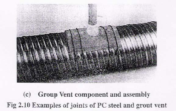
27 2. Steel Prestressing tendons are usually formed from high tensile steel wires or alloy steel bars. The wires can be used singly or twisted together to form strand (usually of seven wires). Several tendons may be arranged in a group with a common anchorage to form a cable (Figure 5.10). Figure 5.10: Types of tendon (from the top): wire, standard strand, drawn strand, cable of seven strands, Dividing bar and Macalloy bar
28 (i) Wire Cold-drawn wire is produced in coil form from hot-rolled rod which is heat treated to make it suitable for cold drawing. The wire surface is initially smooth but may be indented by a subsequent mechanical process. In the as-drawn condition, the wire has a natural curvature approximately equivalent to the capstan of the drawing machine. A final stress-relieving heat treatment to improve some of the mechanical properties of the wire is carried out before it is wound into large diameter coils. The stress-relieving treatment pre-straightens the wire, so that it will pay out straight from the coil, and enhances its elastic and relaxation characteristics. Wire to be used for pre-tensioning is supplied in a de-greased condition and is often indented to ensure that the maximum bond is obtained between steel and concrete. Wire is used in factory-produced items such as lintels and small flooring units.
29 (ii) Strand Strand is made from cold-drawn wires: a seven-wire strand consisting of a straight core wire (the king wire) around which are spun six helical wires in one layer. The diameters of the outer wires have to be slightly less than that of the king wire to allow for their helical form. Strand can be supplied with the outer wires having either a lefthand or a right-hand twist and the stressing jacks need to be adjusted accordingly. In BS 5896, there are three types of seven wire strand: standard, super and drawn (Figure 5.11). Figure 5.11: Cross Sections Of (a) Standard And Super Strand, And (b) Drawn Strand
30 (iii) Bar There are two types of bar in common use: 1. Macalloy bars are produced from hot-rolled carbonchrome steel bars that are then cold-worked by stretching to obtain the specified properties. The bars are available in lengths up to 17.8 m for diameters between 25 mm and 50 mm. Stainless steel bars are available in lengths up to 6 m for diameters between 20 mm and 40 mm. Both types of bar are provided with cold-rolled threads at each end, or over the full length if needed, and can be joined together by threaded couplers to obtain longer tendon lengths. 2. Dywidag threadbars are produced to a German Standard specification in diameters between 20 mm and 40 mm, with a coarse thread extending over the full length of the bar. The bars may be cut to finished length at the factory or on site and couplers can be used to connect or extend bars as required.
31 The matching between types of tendons and their usage is shown in Figure Figure 5.12: Types of tendons and their usage
32 5.8 Strength of Tendons The strength of a prestressing tendon is specified in terms of characteristic load values for the breaking (or failure) load and the 0.1% proof load, which is defined as the load that produces a permanent elongation equal to 0.1% of the gauge length. For wire and strand, the load at lo/o elongation may be used as an alternative to the proof load (Figure 25). The British (BS 5896 and BS 4486) and European (EN 10138) standards include a range of sizes and strengths for each type of tendon, a selection of which is shown in Table 5.2.
33 Table 5.2: Dimensions and properties of wires, 7-wire stands and bars
34 5.9 Prestressing System & Anchorage 1. Pre-Tensioning With pre-tensioning, the wires or strands are held by temporary grips during and after tensioning. The method of tensioning may vary but in all cases the grip consists of a barrel and wedge. Stressing is carried out either by extending the tendons one at a time, or by multi-stressing, where all the tendons are extended at the same time. In both cases, the process starts at the nonjacking end, where grips are forced onto the unstressed tendons close to the anchor plate. Spring-loaded anchors are often used to apply a consistent force and retain the anchor in position when the tendons are being handled. For tendons that are stressed individually, a relatively small power-operated jack is used to enable stressing to be carried out quickly and efficiently. A popular jack for this purpose is shown in Figure Once the controls have been set to pre-determined values, the stressing and anchoring operations are carried out automatically.

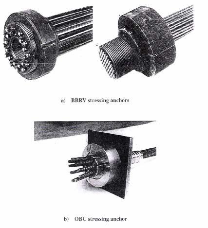
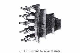
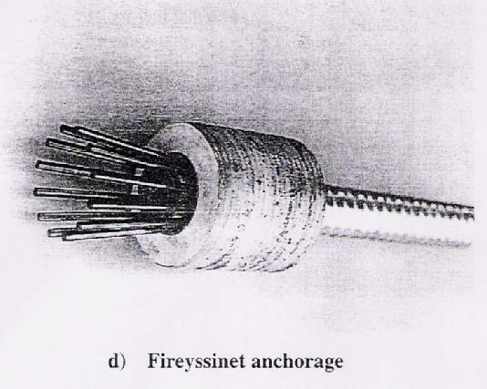
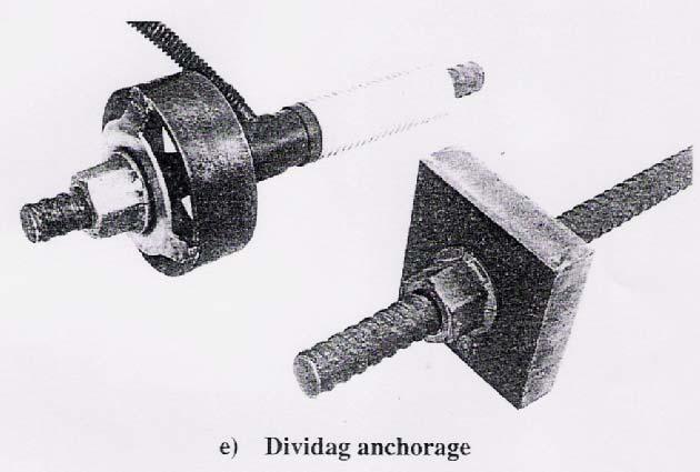
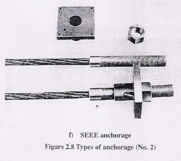
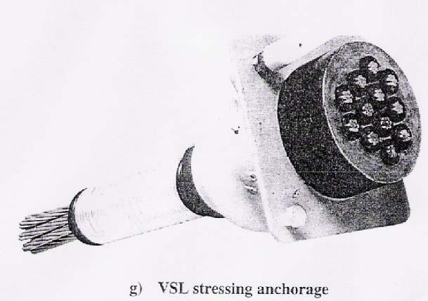
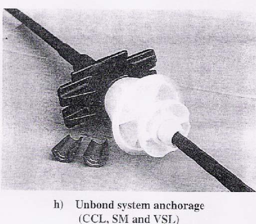
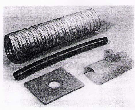
35 2. Post-Tensioning A large number of systems have been developed and used throughout the world as shown in the following photos and Figure 5.14 shows the anchorage systems and their components. Figure 5.13: CCL Stressomatic jacks and pump
36 Figure 5.14: Anchorage system and their components
37
38
39
40 5.10 Loss of Prestress When stress is applied to concrete, it undergoes dimensional changes: an immediate elastic deformation followed by a time-related creep deformation. These changes are in addition to the shrinkage caused by changes in moisture content. Any shortening of the concrete that occurs after the tendons have been tensioned and anchored causes a loss of prestress that must be allowed for in the design of the member. Concrete shrinks over time by an amount that varies with the initial water content of the mix, the thickness of the section and the relative humidity of the environment. The shrinkage develops rapidly at first and continues at a reducing rate for many years. The resulting loss of prestress that occurs in the tendons depends on the age of the concrete at transfer, and is greater with pretensioning than with post-tensioning.
41 The loss of prestress due to the elastic deformation of the concrete that occurs at transfer is greatest in pretensioning, since the tendons are already anchored by bond, and all the stress is applied to the concrete at the same time. In post-tensioning, there is no loss if all the tendons are stressed at the same time, since the elastic deformation takes place before the tendons are anchored. When the tendons are stressed sequentially, a progressive loss occurs in any tendons that are already anchored. The total loss is then intermediate between nil and half the value that occurs in pretensioning. Concrete under applied stress also undergoes an inelastic creep deformation. Like shrinkage, creep develops rapidly at first and continues at a decreasing rate for many years. The creep value depends upon the thickness of the section, the relative humidity of the environment and the maturity of the concrete at transfer of prestress. As a result, the loss of prestress that occurs in the tendons is greater with pre-tensioning than with post-tensioning.
42 5.11 Limitation of Prestressed Concrete Stress The stress limits for prestressed concrete structures under transfer and service condition are stated in clause , EN The stress limits are summarized in Table 5.3. Table 5.3: Stress Limits Stresses Compressive Transfer 0.6f ck (t) Service 0.6f ck Tensile f ctm 0
43 5.12 Stress Distribution Figure 5.15 shows the stress distribution of a simply supported prestress concrete member. Figure 5.15
44 If α = coefficient of short term losses β = coefficient of total losses (short term + long term losses) Stress Distribution at transfer stage. f min = Limit of tensile stress at transfer f max = Limit of compressive stress at transfer
45 Stress Distribution at service stage. f min = Limit of tensile stress at service f max = Limit of compressive stress at service
46 Example 1 Given the following data Moment due to selfweight, Mi = 100 knm, Moment due to external load, Ms = 200 knm Initial prestressing force, P i = 2000 kn (e = 0) Rectangular section: b = 400mm, h = 800mm Sketch the stress distribution diagram and state the stress value
47 Solution: A = bh = 400 x 800 = 320 x 10 3 mm bh 400x800 I = = = 1.7x mm 4 Z I y 1.7x t = Z b = = = 42.5x10 6 mm 3
48 Example 2 The diagram on the left shows a simply supported prestress concrete beam and its cross section. Given the following data: Z b = Z t = x 106 mm 3 Ac = 2.9 x 105 mm 2 α = 0.9 β = 0.8 Concrete strength, f ck = 40 MPa Concrete strength at transfer (7 days), f ck (t) = 28 MPa Check the limiting stress at transfer and service stage.
49 Solution: 3 2.9x10 i = x24 = 10 W 6 M 6.96kN / m 2 2 W i L 696x15 = = 196 knm 8 8 i = 2 2 WL 50x15 M s = M i + = = kNm Limiting stress: f' min = f ctm = 0.3xf ck (t) (2/3) = 0.3(28) (2/3) = 2.77 N/mm 2 f' max = 0.6f ck (t) = 0.6 x 28 = 14 N/mm 2 f min = 0 f max = 0.6f ck = 0.6 x 40 = 24 N/mm 2
50 Stress Distribution At Transfer Stage
51 Stress Distribution At Service Stage
ST7008 PRESTRESSED CONCRETE
 ST7008 PRESTRESSED CONCRETE QUESTION BANK UNIT-I PRINCIPLES OF PRESTRESSING PART-A 1. Define modular ratio. 2. What is meant by creep coefficient? 3. Is the deflection control essential? Discuss. 4. Give
The Hashemite University Department of Civil Engineering. Dr. Hazim Dwairi. Dr. Hazim Dwairi 1
 Department of Civil Engineering Lecture 2.1 Methods of Prestressing Advantages of Prestressing Section remains uncracked under service loads Reduction of steel corrosion (increase durability) Full section
7.1 Transmission of Prestress (Part I)
") 7.1 Transmission of Prestress (Part I) This section covers the following topics. Pre-tensioned Members 7.1.1 Pre-tensioned Members The stretched tendons transfer the prestress to the concrete leading to
7.1 Transmission of Prestress (Part I) This section covers the following topics. Pre-tensioned Members 7.1.1 Pre-tensioned Members The stretched tendons transfer the prestress to the concrete leading to
1.7 Prestressing Steel
 1.7 Prestressing Steel This section covers the following topics. Forms of Prestressing Steel Types of Prestressing Steel Properties of Prestressing Steel Codal Provisions of Steel 1.7.1 Forms of Prestressing
SECTION 1 INTRODUCTION TO POST-TENSIONED CONCRETE DEVELOPED BY THE PTI EDC-130 EDUCATION COMMITTEE
 SECTION 1 INTRODUCTION TO POST-TENSIONED CONCRETE DEVELOPED BY THE PTI EDC-130 EDUCATION COMMITTEE NOTE: MOMENT DIAGRAM CONVENTION In PT design, it is preferable to draw moment diagrams to the tensile
CHAPTER 11: PRESTRESSED CONCRETE
 CHAPTER 11: PRESTRESSED CONCRETE 11.1 GENERAL (1) This chapter gives general guidelines required for the design of prestressed concrete structures or members with CFRM tendons or CFRM tendons in conjunction
POST-TENSIONING APPLICATION AND TECHNOLOGY. Moe Kyaw Aung
 POST-TENSIONING APPLICATION AND TECHNOLOGY Moe Kyaw Aung Overview 1. Background 2. Basic Design Concept 3. Application and Benefits 4. Components of Post-tensioning System 5. Installation Process 6. Construction
POST TENSIONED SLABS. Imagineering the possibilities
 POST TENSIONED SLABS Imagineering the possibilities imagineering... CCL post - tensioned slab solutions represent continuous development through involvement in building structures worldwide. CCL systems
Design for Shear for Prestressed Concrete Beam
 Design for Shear for Prestressed Concrete Beam Introduction The behaviour of prestressed beams at failure in shear is distinctly different from their behaviour in flexure. The beam will tend to fail abruptly
Fundamentals of Prestressed Concrete Bridge
 Fundamentals of Prestressed Concrete Bridge MAB1053 Bridge Engineering Prof. Dr. Azlan Abdul Rahman Universiti Teknologi Malaysia UTM 2006 azlanfka/utm05/mab1053 1 Introduction In prestressed concrete,
1. Cast-in-place concrete is specified in Section
 SECTION 03 38 00 PART 1 - GENERAL 1.01 DESCRIPTION A. This Section describes the requirements for furnishing and installing post-tensioned slabs, jacks, jacking and anchors at Parking Structure, and record
Post-tensioned prestressed concrete bridge - assignment
 Post-tensioned prestressed concrete bridge - assignment Design a post-tensioned prestressed concrete bridge of a three-span arrangement. The construction is prestressed at the age of 7 days and put into
5.4 Analysis for Torsion
 5.4 Analysis for Torsion This section covers the following topics. Stresses in an Uncracked Beam Crack Pattern Under Pure Torsion Components of Resistance for Pure Torsion Modes of Failure Effect of Prestressing
In-plane testing of precast concrete wall panels with grouted sleeve
 In-plane testing of precast concrete wall panels with grouted sleeve P. Seifi, R.S. Henry & J.M. Ingham Department of Civil Engineering, University of Auckland, Auckland. 2017 NZSEE Conference ABSTRACT:
Hyperstatic (Secondary) Actions In Prestressing and Their Computation
 Actions In Prestressing and Their Computation") 5.5 Hyperstatic (Secondary) Actions In Prestressing and Their Computation Bijan O Aalami 1 SYNOPSIS This Technical Note describes the definition, computation, and the significance of hyperstatic (secondary)
5.5 Hyperstatic (Secondary) Actions In Prestressing and Their Computation Bijan O Aalami 1 SYNOPSIS This Technical Note describes the definition, computation, and the significance of hyperstatic (secondary)
An Overview on Tendon Layout for Prestressed Concrete Beams
 P P P Assistant P Assistant P P PG P P HOD, IJISET - International Journal of Innovative Science, Engineering & Technology, Vol. 2 Issue 9, September 2015. An Overview on Tendon Layout for Prestressed
Nonlinear Models of Reinforced and Post-tensioned Concrete Beams
 111 Nonlinear Models of Reinforced and Post-tensioned Concrete Beams ABSTRACT P. Fanning Lecturer, Department of Civil Engineering, University College Dublin Earlsfort Terrace, Dublin 2, Ireland. Email:
Design of Post Tensioned Slab (Review)
") Design of Post Tensioned Slab (Review) Arun S. Bhutekar, Kishor S. Mirge, Bhavna Mhaske, Mangesh J. Sarkate, Prof,N. N. Shinde Department Civil Engineering, Email: bhutekararun143@gmail.com ABSTRACT- The
Design of Post Tensioned Slab (Review) Arun S. Bhutekar, Kishor S. Mirge, Bhavna Mhaske, Mangesh J. Sarkate, Prof,N. N. Shinde Department Civil Engineering, Email: bhutekararun143@gmail.com ABSTRACT- The
Applications of sustainable post-tensioned concrete slabs
 Innov. Infrastruct. Solut. (2017) 2:42 DOI 10.1007/s41062-017-0075-6 TECHNICAL PAPER Applications of sustainable post-tensioned concrete slabs Amr A. Abdelrahman 1 Received: 4 May 2017 / Accepted: 2 June
***************************************************************************************************************
 03365 POST-TENSIONED CONCRETE *************************************************************************************************************** SPECIFIER: CSI MasterFormat 2004 number 03 38 00. ***************************************************************************************************************
Hollow Core Slabs in Construction Industry
 Hollow Core Slabs in Construction Industry Vidya Jose 1, Dr.P. Rajeev Kumar 2 M tech Student, Dept of Civil Engineering, Toc H Institute of Engineering and Technology, Arakunnam, Kerala, India 1 Professor,
Method of Measurement for Road Works Series MM Structural Concrete
 Method of Measurement for Road Works Series MM 1700 - CC-RMP-01700 December 2013 CC Construction & Commissioning Standards TRANSPORT INFRASTRUCTURE IRELAND (TII) PUBLICATIONS About TII Transport Infrastructure
Structural behaviour and failure mechanisms of concrete monoblock railway sleepers
 Structural behaviour and failure mechanisms of concrete monoblock railway sleepers Olli Kerokoski, Antti Nurmikolu and Tommi Rantala Department of Civil Engineering, Tampere University of Technology, P.O.
STRENGTH OF MATERIALS laboratory manual
 STRENGTH OF MATERIALS laboratory manual By Prof. Shaikh Ibrahim Ismail M.H. Saboo Siddik College of Engineering, MUMBAI TABLE OF CONTENT Sr. No. Title of Experiment page no. 1. Study of Universal Testing
TECHNICAL SPECIFICATION FOR PRESTRESSED CEMENT CONCRETE POLES ( F.O.S. 2.5) FOR 11 KV AND LT LINES ( REC SPECIFICATION NO.
 FOR 11 KV AND LT LINES ( REC SPECIFICATION NO.") TECHNICAL SPECIFICATION FOR PRESTRESSED CEMENT CONCRETE POLES ( F.O.S. 2.5) FOR 11 KV AND LT LINES ( REC SPECIFICATION NO. 15 / 1979) MAHARASHTRA STATE ELECTRICITY DISTRIBUTION COMPANY LTD. PAGE 1 OF 7
TECHNICAL SPECIFICATION FOR PRESTRESSED CEMENT CONCRETE POLES ( F.O.S. 2.5) FOR 11 KV AND LT LINES ( REC SPECIFICATION NO. 15 / 1979) MAHARASHTRA STATE ELECTRICITY DISTRIBUTION COMPANY LTD. PAGE 1 OF 7
Bridge Beams. Product brochure
 Bridge Beams Product brochure Bridge Beams Stahlton offers economic bridge systems to suit a variety of spans, loadings and site conditions. Our Super Tee and Single or Double Hollowcore elements are manufactured
Flexure Design Sequence
 Prestressed Concrete Beam Design Workshop Load and Resistance Factor Design Flexure Design Flexure Design Sequence Determine Effective flange width Determine maximum tensile beam stresses (without prestress)
ULTIMATE LOAD-CARRYING CAPACITY OF SELF-ANCHORED CONCRETE SUSPENSION BRIDGE
 ULTIMATE LOAD-CARRYING CAPACITY OF SELF-ANCHORED CONCRETE SUSPENSION BRIDGE Meng Jiang*, University of Technology Dalian, P. R. China Wenliang Qiu, University of Technology Dalian, P. R. China Lihua Han,
UNIVERSITY OF BOLTON WESTERN INTERNATIONAL CENTRE FZE. BEng (HONS) CIVIL ENGINEERING SEMESTER ONE EXAMINATION 2015/2016
 CIVIL ENGINEERING SEMESTER ONE EXAMINATION 2015/2016") OCD59 UNIVERSITY OF BOLTON WESTERN INTERNATIONAL CENTRE FZE BEng (HONS) CIVIL ENGINEERING SEMESTER ONE EXAMINATION 2015/2016 ADVANCED STRUCTURAL ANALYSIS AND DESIGN MODULE NO: CIE6001 Date: Tuesday 12
OCD59 UNIVERSITY OF BOLTON WESTERN INTERNATIONAL CENTRE FZE BEng (HONS) CIVIL ENGINEERING SEMESTER ONE EXAMINATION 2015/2016 ADVANCED STRUCTURAL ANALYSIS AND DESIGN MODULE NO: CIE6001 Date: Tuesday 12
Study of Fracture Properties of Cement Stabilized Macadam
 Study of Fracture Properties of Cement Stabilized Macadam Yinpeng Zhang Zhengzhou Municipal Engineering Design & Research Institute, Zhengzhou 45005, China Abstract By means of three-point bending method,
Sabah Shawkat Cabinet of Structural Engineering 2017
 3.1-1 Continuous beams Every building, whether it is large or small, must have a structural system capable of carrying all kinds of loads - vertical, horizontal, temperature, etc. In principle, the entire
Lecture Retaining Wall Week 12
 Lecture Retaining Wall Week 12 Retaining walls which provide lateral support to earth fill embankment or any other form of material which they retain them in vertical position. These walls are also usually
Strength Design of Reinforced Concrete Structures
 Chapter 6 Strength Design of Reinforced Concrete Structures 6.1 Analysis and Design General Considerations 6.1.1 Convention and Notation Unless otherwise explicitly stated, the following units shall be
BISON PRECAST FLOORING SPECIFICATION
 BISON PRECAST FLOORING SPECIFICATION 1.0 SCOPE OF THE SPECIFICATION 1.01 Relates to: This specification covers the design, manufacture and associated site work of the following types of floors:- Hollowcore
THE PERFORMANCE OF CONCRETE GROUND FLOOR SLAB REINFORCEMENT TO CONTROL SHRINKAGE CRACKING. D H Chisholm 1
 THE PERFORMANCE OF CONCRETE GROUND FLOOR SLAB REINFORCEMENT TO CONTROL SHRINKAGE CRACKING D H Chisholm 1 ABSTRACT In a typical residential concrete floor slab, the cast in strip footings on the slab perimeter
voestalpineaustriadrahtgmbh
 voestalpineaustriadrahtgmbh www.voestalpine.com/austriadraht PRESTRESSING STEEL PRESTRESSING STEEL STRAND BRIGHT Prestressing steel 7 wire strand pren 10138-3 Tensile strength Crosssectional area Mass
Do It Right The First Time, Every Time And On Time. An Introduction to HERCULES LMK PT. Website:
 Do It Right The First Time, Every Time And On Time An Introduction to HERCULES LMK PT Content 1.Introduction 2.Post-Tensioning System 3.Typical Stressing Procedure 4.Typical Preliminary Design 5.PT Slab
DURABILITY AND SERVICEABILITY
 DURABILITY AND SERVICEABILITY Introduction of Durability Durability requirements are to ensure that a structure has satisfactory durability and serviceability performance under normal circumstances throughout
Structural Design of Pergola with Airfoil Louvers
 International Journal of Advanced Structures and Geotechnical Engineering ISSN 2319-5347, Vol. 04, No. 03, July 2015 Structural Design of Pergola with Airfoil Louvers MUHAMMAD TAYYAB NAQASH Aluminium TechnologyAauxiliary
Cintec Ground Anchor Installation at Bridge 325 Abington
 INTRODUCTION: Cintec Ground Anchor Installation at Bridge 325 Abington Search CINTEC.COM: Advanced Search Cintec International Ltd has developed a system of ground anchors incorporating the patented grout
MECHANICS OF MATERIALS
 Lecture Notes: Dr. Hussam A. Mohammed Al- Mussiab Technical College Ferdinand P. Beer, E. Russell Johnston, Jr., and John T. DeWolf Introduction Concept of Stress The main objective of the study of mechanics
SPECIFICATION FOR REINFORCED SOIL WALL
 SPECIFICATION FOR REINFORCED SOIL WALL 1.0 EXTENT OF WORK The work shall consist of Reinforced Soil walls built in accordance with this specification and in conformity with the lines, levels and details
USE OF 500 GRADE STEEL IN THE DESIGN OF REINFORCED CONCRETE SLAB. Prof. M. Shafiul Bari, Ph.D Department of Civil Engg., BUET
 1.0 Introduction USE OF 500 GRADE STEEL IN THE DESIGN OF REINFORCED CONCRETE SLAB Prof. M. Shafiul Bari, Ph.D Department of Civil Engg., BUET There is growing interest within the reinforced concrete industry
Seismic Detailing of RC Structures (IS: )
") Seismic Detailing of RC Structures (IS:13920-1993) Sudhir K Jain Indian Institute of Technology Gandhinagar November 2012 1 Outline This lecture covers: Covers important clauses of IS13920 With particular
Seismic Detailing of RC Structures (IS:13920-1993) Sudhir K Jain Indian Institute of Technology Gandhinagar November 2012 1 Outline This lecture covers: Covers important clauses of IS13920 With particular
Practical Prestress Detailing
 Practical Prestress Detailing Disclaimer: "This presentation is for guidance only & is not to be taken as specific advice applicable to a particular project." This presentation will only cover bonded post-tensioning,
Material Requirements for Steel and Concrete Structures
 Material Requirements for Steel and Concrete Structures Chiew Sing-Ping School of Civil and Environmental Engineering Nanyang Technological University, Singapore Materials Concrete Reinforcing steel Structural
mortarless Design Manual Part 1 (AS 3600:2009) Section 1 Page 1 AS 3600:2009 PLAIN AND REINFORCED CONCRETE - CODE OF PRACTICE
 Section 1 Page 1 AS 3600:2009 PLAIN AND REINFORCED CONCRETE - CODE OF PRACTICE") SECTION 1. mortarless Design Manual Part 1 (AS 3600:2009) Section 1 Page 1 AS 3600:2009 PLAIN AND REINFORCED CONCRETE - CODE OF PRACTICE 1.1 Overview of AS 3600:2009 AS 3600:2009 is the latest Australian
SECTION 1. mortarless Design Manual Part 1 (AS 3600:2009) Section 1 Page 1 AS 3600:2009 PLAIN AND REINFORCED CONCRETE - CODE OF PRACTICE 1.1 Overview of AS 3600:2009 AS 3600:2009 is the latest Australian
THEORETICAL AND EXPERIMENTAL STUDY OF UNBOUNDED POST-TENSIONED CONTINUOUS SLAB DECKS CONSISTING OF HIGH STRENGTH SCC
 CD02-017 THEORETICAL AND EXPERIMENTAL STUDY OF UNBOUNDED POST-TENSIONED CONTINUOUS SLAB DECKS CONSISTING OF HIGH STRENGTH SCC A.A. Maghsoudi 1, M. Torkamanzadeh 2 1 Associate. Prof., Civil Engineering.
R-Group Finland Oy. RTA, RWTL and RWTS Lifting anchors Design instructions
 R-Group Finland Oy RTA, RWTL and RWTS Lifting anchors Design instructions According to Eurocodes, EU Machinery directive 2006/42/EC and VDI/BV-BS 6205 CE Approved 28.12.2016 2 Table of contents 1 DESCRIPTION
Chapter 2: Strain. Chapter 3: Torsion. Chapter 4: Shear and Moment Diagram
 Chapter 2: Strain Chapter 3: Torsion Chapter 4: Shear and Moment Diagram Strain - Is defined as change in length per unit length, simply put it is unit deformation L Stress and Strain Exist concurrently
1 Exam Prep Placing Reinforcing Bars Tabs and Highlights
 1 Exam Prep Placing Reinforcing Bars Tabs and s These 1 Exam Prep Tabs are based on the CRSI Placing Reinforcing Bars Recommended Practices, 9 th Edition. Each 1 Exam Prep tabs sheet has five rows of tabs.
Anchor Load Cells Installation - considerations
 Anchor Load Cells Installation - considerations This article outlines the main points to check during installation of load cells to control tensions while installing and service life, applied on bar and
INTERNATIONAL JOURNAL OF CIVIL AND STRUCTURAL ENGINEERING Volume 3, No 1, 2012
 INTERNATIONAL JOURNAL OF CIVIL AND STRUCTURAL ENGINEERING Volume 3, No 1, 2012 Copyright by the authors - Licensee IPA- Under Creative Commons license 3.0 Research article ISSN 0976 4399 Finite element
Parametric Study of Continuous Concrete Beam Prestressed with External Tendon
 Parametric Study of Continuous Concrete Beam Prestressed with External Tendon Assistant Professor, College of Engineering, Diyala University, Iraq ABSTRACT This paper presents the results of a parametric
INDUSTRIAL BUILDINGS ARE R ENOVATION. By John M. Wathne, P.E.
 R ENOVATION PRACTICAL THERMAL PRESTRESSING Existing joists in an industrial building were successfully reinforced in part through the use of thermal prestressing while still under load By John M. Wathne,
STRENGTHENING OF UNBONDED POST-TENSIONED CONCRETE SLABS USING EXTERNAL FRP COMPOSITES
 STRENGTHENING OF UNBONDED POST-TENSIONED CONCRETE SLABS USING EXTERNAL FRP COMPOSITES F. El M e s k i 1 ; M. Harajli 2 1 PhD student, Dept. of Civil and Environmental Engineering, American Univ. of Beirut;
Technical Notes POST-TENSIONING IN GROUND-SUPPORTED SLAB 1. Bijan O Aalami 2 First draft
 Post-Tensioning Expertise and Design August 11, 2014 TN207_sog_stresses_4 POST-TENSIONING IN GROUND-SUPPORTED SLAB 1 Bijan O Aalami 2 First draft CONTENTS C.1 OVERVIEW C.2 ENGINEERS BENDING STRESS ASSUMPTIONS
1. Introduction. 3. Advantages of Pre-Stressed Concrete. 2. Basic Concepts of Pre-Stressing. Rajamoori Arun Kumar 1, B.
 Design of Pre-Stressed Concrete T-Beams Rajamoori Arun Kumar 1, B. Vamsi Krishna 2 1 M.Tech Scholar, Structural Engineering,, Malla Reddy Engineering College (Autonomous), Secunderabad-500100, India 2
Introduction to Structural Analysis TYPES OF STRUCTURES LOADS AND
 AND Introduction to Structural Analysis TYPES OF STRUCTURES LOADS INTRODUCTION What is the role of structural analysis in structural engineering projects? Structural engineering is the science and art
HIGH PERFORMANCE REINFORCEMENT PRODUCTS. Product Catalogue.
 HIGH PERFORMANCE REINFORCEMENT PRODUCTS Product Catalogue www.hrc-europe.com HRC and its product philosophy The use of T-headed bars in concrete structures has some remarkable benefits compared to the
ITEM 426 PRESTRESSING Definitions. For this Item, the following definitions shall apply:
 ITEM 426 PRESTRESSING 426.1. Description. This Item shall govern for the furnishing, fabricating, storing and handling of prestressing materials, for the prestressing of precast members, and for the prestressing
Concrete-filled fiber reinforced polymer tube-footing interaction in bending
 Fourth International Conference on FRP Composites in Civil Engineering (CICE2008) 22-24July 2008, Zurich, Switzerland Concrete-filled fiber reinforced polymer tube-footing interaction in bending Y. C.
Mechanical behavior of crystalline materials - Stress Types and Tensile Behaviour
 Mechanical behavior of crystalline materials - Stress Types and Tensile Behaviour 3.1 Introduction Engineering materials are often found to posses good mechanical properties so then they are suitable for
Steel fibres Structural applications
 WireSolutions Steel fibres Structural applications TAB-Slab TAB-Structural TAB-Deck TAB-Raft ArcelorMittal & WireSolutions Transforming tomorrow ArcelorMittal ArcelorMittal is the world leader in the steel
Design Guide for Concrete Toppings to Beam & EPS Block Suspended Floors
 Design Guide for Concrete Toppings to Beam & EPS Block Suspended Floors September 2017 Cooperating organizations BBA BPF (British Plastics Federation) British Precast PFF BRMCA Concrete Society Grace Construction
REVIEW ON SHEAR SLIP OF SHEAR KEYS IN BRIDGES
 REVIEW ON SHEAR SLIP OF SHEAR KEYS IN BRIDGES Benjamin Raison R; Freeda Christy C PG student, School of Civil Engineering, Karunya University. Associate Professor, School of Civil Engineering, Karunya
Bulk Deformation Processes
 Bulk Deformation Processes Bachelor of Industrial Technology Management with Honours Semester I Session 2013/2014 TOPIC OUTLINE What is Bulk Deformation? Classification of Bulk Deformation Processes Types
fischer Test Report Fixing Tests for Bison Hollow Core Slabs
 fischer Test Report Fixing Tests for Bison Hollow Core Slabs Testing on Bison Hollow Core Slabs 1. Introduction Contents Test Parameters Bison Hollow Core Slab Information 2. Fixings Products Tested FISV
Ultimate strength prediction for reinforced concrete slabs externally strengthened by fiber reinforced polymer (FRP)
") Ultimate strength prediction for reinforced concrete slabs externally strengthened by fiber reinforced polymer (FRP) Abstract This paper presents the potential use of externally bonded fiber reinforced
Ultimate strength prediction for reinforced concrete slabs externally strengthened by fiber reinforced polymer (FRP) Abstract This paper presents the potential use of externally bonded fiber reinforced
HOLLOW CORE FLOORS SPEED AND STRENGTH
 HOLLOW CORE FLOORS SPEED AND STRENGTH CONTENTS 2 3 4 5 7 8 9 10 12 13 14 INTRODUCTION PRECAST CONCRETE FLOORS T HE A DVANTAGES BISON HOLLOW CORE FLOORS BEARINGS FALSE CEILINGS AND SOFFIT FIXINGS BISON
Concrete and Masonry structures 3
 Concrete and Masonry structures 3 133CM03 Model Homework 1 Post-tensioned prestressed concrete bridge - assignment Design a post-tensioned prestressed concrete bridge of a three-span arrangement. The construction
Scientific Seminar Design of Steel and Timber Structures SPbU, May 21, 2015
 Riga Technical University Institute of Structural Engineering and Reconstruction Scientific Seminar The research leading to these results has received the funding from Latvia state research programme under
BRIDGE GIRDERS TECHNICAL GUIDE
 ARMTEC.COM BRIDGE MATERIALS / / TECHNICAL GUIDE REGIONal SPECIFICATIONS / AB / MB / SK PRECAST CONCRETE GIRDERS AND BEAMS DESIGNED TO SUPPORT BRIDGE DECKS AND TRAFFIC LOADS Proven strength In-house engineering
SECTION VIBRATION CONTROLS FOR HVAC PIPING AND EQUIPMENT
 SECTION 230548 - PART 1 - GENERAL 1.1 SUMMARY A. This Section includes the following: 1. Elastomeric Isolation pads. 2. Elastomeric Isolation mounts. 3. [Freestanding] [Restrained] [Freestanding and restrained]
St.MARTIN S ENGINEERING COLLEGE
 St.MARTIN S ENGINEERING COLLEGE Dhulapally, Secunderabad-500 014 Subject: STRENGTH OF MATERIALS - II Class : Civil II Part-A (Short Answer Questions) UNIT-I 1 Define a) Torque b) Torsional moment of resistance
Design and Construction of the SH58 Ramp A Flyover Bridge over IH70. Gregg A. Reese, PE, CE, Summit Engineering Group, Inc.
 Design and Construction of the SH58 Ramp A Flyover Bridge over IH70 Gregg A. Reese, PE, CE, Summit Engineering Group, Inc., Littleton, CO ABSTRACT: The SH58 Ramp A bridge in Golden, CO is the latest on
Nonlinear Analysis of Shear Dominant Prestressed Concrete Beams using ANSYS
 Nonlinear Analysis of Shear Dominant Prestressed Concrete Beams using ANSYS Job Thomas Indian Institute of Science, Bangalore, India Ananth Ramaswamy Indian Institute of Science, Bangalore, India Abstract
Fundamentals of Post-Tensioned Concrete Design for Buildings
 Fundamentals of Post-Tensioned Concrete Design for Buildings Part One by John P. Miller www.suncam.com Copyright 2012 John P. Miller Page 1 of 49 Overview of This Course This is Part One of a three-part
Experimental Research of Bridges with Encased Beams
 Experimental Research of Bridges with Encased Beams VINCENT KVOČÁK VIKTÓRIA KOŽLEJOVÁ Institute of Structural Engineering, Civil Engineering Faculty Technical University in Košice Vysokoškolská 4, 042
MECHANICAL PROPERTIES
 MECHANICAL PROPERTIES Mechanical Properties: In the course of operation or use, all the articles and structures are subjected to the action of external forces, which create stresses that inevitably cause
UHPC Connection of Precast Bridge Deck
 Jan L. Vitek, Metrostav, a.s. and CTU in Prague Jiri Kolisko, CTU in Prague, Klokner Institute David Citek, CTU in Prague, Klokner Institute Stanislav Rehacek, CTU in Prague, Klokner Institute Robert Coufal,
Cement grouted steel bars in glulam
 Cement grouted steel bars in glulam Buchanan, Andrew H 1, Moss, Peter J 1 and Eistetter, Sabine 2 ABSTRACT This paper describes an experimental investigation into the use of cement grout for bonding threaded
The strength of a material depends on its ability to sustain a load without undue deformation or failure.
 TENSION TEST The strength of a material depends on its ability to sustain a load without undue deformation or failure. This strength is inherent in the material itself and must be determined by experiment.
ADAPT-PT 2010 Tutorial Idealization of Design Strip in ADAPT-PT
 ADAPT-PT 2010 Tutorial Idealization of Design Strip in ADAPT-PT Update: April 2010 Copyright ADAPT Corporation all rights reserved ADAPT-PT 2010-Tutorial- 1 Main Toolbar Menu Bar View Toolbar Structure
CSU GUIDELINES. April 27, 2018 FOR POST-TENSIONED CONCRETE STRUCTURES.
 CSU GUIDELINES FOR POST-TENSIONED CONCRETE STRUCTURES April 27, 2018 http://www.calstate.edu/cpdc/ae California State University Seismic Review Board Technical Guidelines January 9, 2018 The CSU Seismic
Finite Element Simulation of Cantilever Construction Structure
 Finite Element Simulation of Cantilever Construction Structure Baofeng Pan 1, Gang Li 2 Abstract In order to realize the control ultimate goal, it is necessary to predict and control the deformation and
Over the years, the use of precast concrete has taken giant
 Precast Concrete Bridge Deck - Design, Transportation and Erection: A Designer s Overview Debabrata Mukherjee 1, Manju Balaji 2 1 Group Engineer, Atkins 2 Engineer, Atkins 76 Over the years, the use of
Chapter. Masonry Design
 Chapter Masonry Design The masonry design section contains modules for the analysis of reinforced masonry beams subjected to pure bending and unreinforced masonry walls subjected to axial compression and
CRACKING BEHAVIOR AND CRACK WIDTH PREDICTIONS OF CONCRETE BEAMS PRESTRESSED WITH BONDED FRP TENDONS
 CRACKING BEHAVIOR AND CRACK WIDTH PREDICTIONS OF CONCRETE BEAMS PRESTRESSED WITH BONDED FRP TENDONS Weichen XUE Professor Tongji University Siping Road 1239#, Shanghai 200092, China xuewc@tongji.edu.cn*
THE DESIGN OF LONG CANTILEVER BEAM USING POST-TENSIONED TENDONS IN KUMJUNG STADIUM
 D.S. Choi (E-353) 1/6 THE DESIGN OF LONG CANTILEVER BEAM USING POST-TENSIONED TENDONS IN KUMJUNG STADIUM Dong-Sub Choi Jong-Soo Kim Dong-Hwan Kim C.S Structural Engineers Inc., #413-4, Tokok2 dong, Kangnam-Gu,
Introduction. 1. Outline of fan case ring
 A near-net-shape (NNS) ring-rolling process was developed to reduce the forging weight of a rolled, fan case front, ring made of Ti-6Al-4V. This was achieved by optimizing the ring-rolling process in which
Unit 48: Structural Behaviour and Detailing for Construction. Limit State Design
 2.1 Introduction Limit State Design Limit state design of an engineering structure must ensure that (1) under the worst loadings the structure is safe, and (2) during normal working conditions the deformation
Reinforced Concrete Design. A Fundamental Approach - Fifth Edition
 CHAPTER REINFORCED CONCRETE Reinforced Concrete Design A Fundamental Approach - Fifth Edition Fifth Edition REINFORCED CONCRETE A. J. Clark School of Engineering Department of Civil and Environmental Engineering
specification sheet for approval
 BMVIT-327.2/6-II/ST2/2 specification sheet for approval (Translation from the German original has not been certified by any authorities) Object of approval: ANP Micropiles SAS 55 with load - bearing s
Properties in Shear. Figure 7c. Figure 7b. Figure 7a
 Properties in Shear Shear stress plays important role in failure of ductile materials as they resist to normal stress by undergoing large plastic deformations, but actually fail by rupturing under shear
DESIGN OF STEEL FIBRE REINFORCED CONCRETE BEAMS USING THE NEW FIB MODEL CODE 2010 AN EVALUATIVE
 147 Paper No. 739 DESIGN OF STEEL FIBRE REINFORCED CONCRETE BEAMS USING THE NEW FIB MODEL CODE 2010 AN EVALUATIVE AMMAR ABID, K. B. FRANZEN 148 Ammar Abid, K. B. Franzen 72 nd Annual Session of Pakistan
Chapter Five Torsion. Reinforced Concrete Structures 2 (CEng-3122)
") Reinforced Concrete Structures 2 (CEng-3122) Chapter Five Torsion 1 School of Civil and Environmental Engineering Concrete Material and Structures Chair 2 1. Introduction 2. Torsional Resistance 3. Analysis
Reinforced Concrete Structures 2 (CEng-3122) Chapter Five Torsion 1 School of Civil and Environmental Engineering Concrete Material and Structures Chair 2 1. Introduction 2. Torsional Resistance 3. Analysis
EN REINFORCED MASONRY DESIGN EXAMPLE 1 (NOTE: THIS USES THE UK NATIONAL ANNEX NDP VALUES)
") 42.50 10.00 3.00 20.00 EN 1996-1-1 REINFORCED MASONRY DESIGN EXAMPLE 1 (NOTE: THIS USES THE UK NATIONAL ANNEX NDP VALUES) Reinforced Masonry - Reinforced Brickwork Stem Cantilever Pocket-Type Retaining
42.50 10.00 3.00 20.00 EN 1996-1-1 REINFORCED MASONRY DESIGN EXAMPLE 1 (NOTE: THIS USES THE UK NATIONAL ANNEX NDP VALUES) Reinforced Masonry - Reinforced Brickwork Stem Cantilever Pocket-Type Retaining
Comparative Study of R.C.C and Steel Concrete Composite Structures
 RESEARCH ARTICLE OPEN ACCESS Comparative Study of R.C.C and Steel Concrete Composite Structures Shweta A. Wagh*, Dr. U. P. Waghe** *(Post Graduate Student in Structural Engineering, Y.C.C.E, Nagpur 441