ALBLItZ 70 S INSTRUCTION FOR ERECTION AND USE
|
|
|
- Audrey Stone
- 6 years ago
- Views:
Transcription


1 ALBLItZ 70 S INSTRUCTION FOR ERECTION AND USE


2 Approval No. Z Standard Version (as of )
3 C O N T E N T S 1. General Erecting the scaffold General requirements Erecting the first bay Load-distributing bed Foot plates, foot spindles Levelling frame Frames Decking Diagonal braces Aligning Erecting further bays Standard bay Corner figuration Ladder access Erecting further scaffold layers Principles Handling scaffold components Assembling vertical frames and guardrail Decking Diagonal braces Completing the side protection Scaffold retainers Scaffold anchors Anchor grids and forces Fee-standing top scaffold layer Installing supplementary components Widening brackets Protective shelter Roof safety scaffold Passageway frame Bridging Variations and installation of supplementary components General Standard versions of uncovered scaffolds Standard versions of net or tarpaulin-covered scaffolds Use Dismantling scaffolds System components...70 Seite I
4 1. General The façade scaffolding, teel, is a frame-type steel scaffolding of prefabricated components. The bay sizes are 1.57 m, 2.07 m, 2.57 m, 3.07 m and 4.14 m; the scaffolding width is 0.73 m. The scaffold may be used as a working scaffold for the scaffolding groups 1 to 3 in compliance with DIN (effective load per unit area 200 kg/m 2 in scaffolding group 3) and as a safety and roof safety scaffold (falling height max. 2.0 m). Proof of standard version is furnished for an erection height of 24 m plus spindle extension length. These instructions for shall only apply to scaffold uses as technological equipment for industrial purposes. These instructions describe how to erect, convert and dismantle the standard version of this scaffold. Scaffolds may only be erected, converted or dismantled under the supervision of a qualified person and by personnel specially instructed on how to carry out such work. If the scaffolding system is used for scaffolds deviating from the standard version, these deviations must be evaluable according to both the Technical Building Regulations and the stipulations of the National Technical Approval Z and are to be calculated on a caseto-case basis. The decks used for the façade scaffolding are verified for the live loads of scaffolding groups listed in Table 1 according to DIN All decks may be used in safety and roof safety scaffolds up to a falling height of max. 2.0 m. Page 1/75
5 Table 1: Use of decking Designation Z Annex Bay size l [m] Use for safety and roof safety scaffold Use in scaffold group 2,07 admissible 6 Steel deck 0.32 m 30 2,57 admissible 5 3,07 admissible 4 Steel deck 4.14x0.32 m 31 4,14 admissible 3 2,07 admissible 6 Steel deck 0.19 m 32 2,57 admissible 5 3,07 admissible 4 Steel hatch-typeaccess deck0.64 m 33 2,57 admissible 3 Aluminium deck / Aluminium chequer plate deck 0.32 m 34 Aluminium box-type deck 35 Aluminium profile deck EURO steel deck 37 1,57 admissible 3 2,07 admissible 5 2,57 admissible 4 3,07 admissible 6 2,57 admissible 6 3,07 admissible 5 1,57 admissible 6 2,07 admissible 5 3,07 admissible 4 2,57 admissible 3 2,07 admissible 5 2,57 admissible 4 3,07 admissible 3 Sturdy deck 0.61 m 38 3,07 admissible 3 Sturdy hatch-type access 39 3,07 admissible 3 Sturdy hatch-type access with integrated 40 3,07 admissible 3 ladder 2,07 admissible 5 Sturdy deck 0.32 m 41 2,57 admissible 4 3,07 admissible 3 Combined atcking deck 42, 43 3,07 admissible 3 Hatch-type access combined deck 44 3,07 admissible 3 Hatch-type access combined deck w. ladder 45 3,07 admissible 3 Combined deck 47,48 3,07 admissible 3 Combined hatch-type deck 49 3,07 admissible 3 Solid wooden plank 50 3,07 admissible 3 Solid wooden frame deck 0.31 and 0.61 m 51, 52, 53 3,07 admissible 3 2,07 admissible 6 Steel deck 80 2,57 admissible 5 3,07 admissible 4 Solid wooden deck 88 3,07 admissible 3 2,57 admissible ,07 admissible 3 Aluminium deck with plywood 82 2,57 admissible ,07 admissible 3 Alu hatch-type acc. deck 86 3,07 admissible 3 with integrated ladder 85 2,57 admissible 3 Page 2/75
6 2. Erecting the scaffold 2.1 General requirements Prior to erection check the scaffold components for any defects. Never use defective components. Erect the scaffold in the order described below. 2.2 Erecting the first bay Load-distributing bed The scaffold must always be set up on a sufficiently strong base. If this is not the case use load-distributing beds in the form of timber planks to be provided under the two scaffold standards, see Fig Foot plates, foot spindles Provide a foot plate or foot spindle under each scaffold standard. The foot spindles may be fully extended but no more than 41 cm, see Fig. 1. For this purpose observe the instructions for the individual standard version in Chapter 3. Fig. 1: Load-distributing beds with timber planks, spindle extension Page 3/75
7 2.2.3 Levelling frame For slopes, sharp elevation differences and to specific certain scaffold layer heights levelling frames can be used at the foot of the scaffold, see Fig. 2. Fig. 2:Levelling frame Page 4/75
8 2.2.4 Frames Position vertical or passageway frames vertically and at the given distance to the façade onto the foot plates or foot spindles and protect the same against falling by installing a guardrail brace. Fig. 3: Erecting the first scaffold bay Decking Suspend decks between the upper U-ledgers of the vertical frame. Use two narrow decks (32 cm in width) or one wide deck (60 cm in width) for the 0.73 m wide vertical frames. When using passageway frames provide decks over the entire width, i.e. four narrow or two wide decks. In scaffold group 3 all kinds of decks can be used. Page 5/75
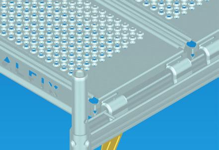
9 2.2.6 Diagonal braces Provide a diagonal brace as longitudinal bracing at the exterior of the bay, also see Fig. 4. For this purpose insert the shaped end of the diagonal brace into the opening of the gusset plate, swivel downwards until the halfcoupler can be closed at the opposite frame. Also install in this bay a horizontal strut at the exterior of the scaffold above the lower transoms. With some kinds of erection it will also be necessary to provide diagonal braces and horizontal struts on the inside of the scaffold. Fig. 4: Completed first bay Aligning Align the first bay vertically and horizontally. Check the wall distance. Page 6/75
10 2.3 Erecting further bays Standard bay The other bays have to be erected as described above starting from the first bay. As a minimum provide each 5th bay again with a longitudinal brace that consists of a diagonal brace and a horizontal strut. The required number of diagonal and horizontal braces can be gathered from the standard version given in chapter 2. Several kinds of erection will also need cross diagonal braces to be provided in the lower vertical frames. For versions using brackets it is absolutely essential to provide aluminium double guardrails Corner figuration The scaffold for building corners has to be provided as shown in Fig. 5. Connect two vertical frames at an angle of 90 using two swivel couplers - one of them in the recess of the gusset plates. Now, provide a base jack only under these standards. In the course of further erection these standards have to be connected with a swivel coupler again at a height distance of 4 m. Also anchor the neighbouring standards at a height distance of maximum 4 m using triangular ties. Page 7/75
11 Fig. 5: Corner figuration (side protection not shown) Page 8/75
12 2.3.3 Ladder access Before you start working on the first scaffold layer provide an inner ladder for access to higher levels. For this purpose different hatch-type access decks are available. On the lowest level of the ladder area install two transoms or U-transoms into which a deck supporting the first ladder is to be placed. Always keep the hatches of the access decks closed when not used for access. Preferably arrange the passageways in a staggered manner. Fig. 6: Ladder access Page 9/75
13 2.4 Erecting further scaffold layers Principles Carry out all scaffolding so that falling is prevented or the risk of falling is kept at a minimum. Protective measures are: - technological protective measures - personal protective equipment to prevent falling - specific instructions As a technological protective measure ALFIX provides the advanced guardrail post with telescopic guardrail, see chapter If the scaffold contractor concludes after risk assessment that another protective measure should be taken, this has to be documented in separate use instructions. If "Personal protective equipment to prevent falling" in compliance with BGR 198 1) is to be used, it will be necessary to use the fastening points provided at the scaffold as shown in chapter Risk assessment must also include any potential rescue of a person who has fallen down. Personal protective equipment may be life lines with integrated fall damper with the rope being max 4 m long. The selfsecuring one-hand spring hook must have an opening width of min. 50 mm. 1) BGR 198 (formerly ZH 1/709): Use of personal protective equipment against falling. Hauptverband der gewerblichen Berufsgenossenschaften; as amended in Regulations by employer's insurance association can be downloaded from Handling scaffold components For scaffolds higher than 8 m (deck height over erection area) it is necessary to use builder's hoists. This also includes hand-operated pully tackles. No such builder's hoists need to be used if the scaffold height does not exceed 14 m and the linear extension of the scaffold is maximum 10 m. In scaffold bays where vertical handling is done by hand, guardrail and intermediate braces must be in place. For such manual handling at least one person must be involved on each scaffold layer. Page 10/75
14 2.4.3 Assembling vertical frames and guardrail Advanced guardrails Advanced guardrail posts with telescopic guardrails provide a temporary side protection over the entire scaffold layer. On the first layer (standing height 2 m) the components have to be assembled from the floor. On the other levels the advanced guardrail post and the two connected telescopic guardrails have to be relocated vertically only. Erection shall start at the front face of the scaffold. Mount the advanced end guardrail on the guardrail post using the M10x60 bolt, see Fig Suspend a telescopic guardrail from the hook at the post and mount the post on the corner member of the scaffold, see Fig. 7-2: - Put up the guardrail post on the outer side of the assembly frame with the lower fork located on the guardrail brace of the lower scaffold layer. - The upper fork embraces the standard tube below the gusset plate and is secured by closing the wedge (hammer blow). Now, mount a guardrail post on the inner member threading the end guardrail into the suspension hooks, see Fig Then, mount the guardrail along the façade. Suspend the other end of the telescopic guardrail in the next guardrail post, and also another telescopic guardrail, Fig Now, lift the guardrail post and the telescopic guardrail and install it in the next assembly frame as described before, see Fig Suspension of the telescopic guardrails and installation of the next guardrail post with guardrails being suspended is repeated over the entire length of the scaffold. The advanced guardrail must have been provided on the entire scaffold layer before this level may be accessed and the assembly frames and the normal three-piece side protection erected, see Fig The following scaffold layer has to be protected to prevent falling by vertically relocating the advanced guardrail post with telescoping guardrails being connected on both sides, see Fig Page 11/75
15 Fig. 7-1: Preparing the guardrail post with advanced end guardrail Fig. 7-2: Mounting an advanced guardrail post with end guardrail and telescopic guardrail Fig. 7-3: Mounting the advanced guardrail post on inner member Page 12/75
16 Fig. 7-4: Mounting the guardrail post with other end of telescopic guardrail and another telecopic guardrail Fig. 7-5:Completing the advanced guardrail over entire scaffold layer Page 13/75
17 Fig. 7-6: Erecting the next scaffold layer (assembly frame, decks, stiffener, 3-piece side protection) protected by the advanced guardrail. Fig. 7-7:Vertical relocation of advanced guardrail post and telescopic guardrail Page 14/75
18 Fixing points for personal protective equipment against falling If personal protective equipment is to be worn, the following fixing points can be used: - frame corner (in gusset plate or at standard tube in the corner) (Fig. 8-1) - assembly frame above or directly within the scaffold box (Fig. 8-2) - guardrail brace (Fig. 8-3) Using spring hooks in accordance with DIN EN 362 with an opening width of 50 mm as lifting tackle. First access to scaffold layer: Fix the spring hook in the frame corner on the external side of scaffold. For this purpose hook the spring hook from above, while standing on the ladder, on the external side in the frame corner, see Fig A scaffold bay consisting of two assembly frames and a guardrail brace can be put up using this kind of protection. For further erection work the a. m. fixing points may also be used at freestanding assembly frames. Fig. 8-1: Fixing point in frame corner Fig. 8-2: Fixing point above or within the scaffold box (outside and inside of scaffold) Fig. 8-3: Fixing point at guardrail brace Fig. 8-4: Fixing in frame corner on the outside of scaffold for initial access of scaffold layer Page 15/75
19 2.4.4 Decking Provide the decking as described in chapter Always mount the decking starting from the lower secured scaffold layer. Protect the decks against accidental lift-out with the foot ledgers of the next scaffold layer, on the top scaffold layer withthe guardrail post or guard system support. Always provide separate deck retainers if there is no protection against lift-out by components arranged above, see Fig. 13, for example. The bracket 36 has a lift-out protection for the bracket deck Diagonal braces Mount diagonal braces continually as the scaffold erection progresses. They may be mounted either in a tower-like manner or continuously. The necessary number of diagonal braces can be gathered from the standard versions in chapter Completing the side protection Provide missing intermediate stringers and toeboards and the complete side protection at the end on all scaffold layers that are not exclusively used for scaffold erection Scaffold retainers To tie scaffolds to the façade, quick anchors provided with U-shaped anchor tabs, continuous scaffold retainers with and without anchor couplers are available. To this extent, no inner bracket has been provided in the opening of the gusset plate. The continuous retainer or quick anchor can be connected by use of standard couplers (see Figs. 9a and 9b). The tab of the quick anchor embraces the U-transom of the vertical frame. The continuous scaffold retainer is connected to a second standard coupler at the outer assembly frame. If an inner bracket has been provided, the continuous scaffold retainer must be connected there using an anchor coupler (see Fig. 10 a). If an outer bracket has been connected, it will be necessary to provide scaffold retainers for tying. The scaffold retainer must be connected below the bracket brace to the inner assembly frame using a standard coupler (see Fig. 10b). Triangular ties are required for the individual arrangements (Fig. 11). They are formed of V-shaped pairs of retainers that are connected to the inner assembly frame at an angle of 45 to the vertical frame. In individual cases connections up to 0.4 m below the transom are allowed. Page 16/75
20 Fig. 9a: Quick-release anchor Fig. 9b: Continuous scaffold retainer Fig.10: Continuous scaffold retainer Fig. 10b: Scaffold retainer Page 17/75
21 Fig. 11: Triangular ties Page 18/75
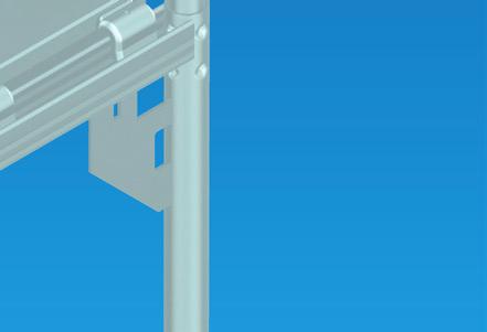
22 2.4.8 Scaffold anchors Provide the scaffold anchors in line with scaffold erection. For this also see chapter 7.6 "Anchoring" of BGR 166 1). As fasteners use eye bolts for scaffold erection that are minimum 12 mm in diameter and plastic expansion fasteners or similar depending on the load-carrying capacities required. 1) BGR 166: System scaffolds (frame and modular scaffolds) When applying the content of BGR 166 also observe the operational safety regulations (BetrSichV) Anchor grids and forces The planned anchor grids can be gathered from the standard versions shown in Figs. 18 to 52. The relevant anchor forces are shown there. All kinds of erection and attachments are covered herein. The indicated forces are service loads Free standing top scaffold layer While buildings are constructed temporary conditions may occur where a work level projects free-standingly over the top cantilevered level, see Fig. 12. So, it is necessary to secure the post joints by couplers in the area above the anchoring. Fig. 12: Top unanchored scaffold layer Page 19/75
23 2.5 Installing supplementary components Widening brackets To widen the decks, two brackets are available. The brackets and - if possible - the decks may only be mounted from the secured lower scaffold layer. Otherwise safety measures have to be defined and applied after separate risk assessment. Inner bracket (bracket 36 resp. bracket 0.36 m) Use the inner bracket together with a narrow deck (32 cm wide) inside the scaffold, see Fig. 13. Connect the semicoupler welded to the bracket in the opening of gusset plate of the vertical frame. The decking has to be protected against accidental lift-out with the lift-out protection of the bracket. For the previous bracket type of 0.36 m which has no integrated lift-out protection, it is necessary to install such protection, see Fig. 14. The bracket may be installed on the inside on every scaffold layer. Fig. 13: Inner bracket (bracket 36cm resp. bracket 0.36 m) Page 20/75
24 Outer bracket (bracket 73 resp. bracket 0.73 m or bracket 0,73m reinforced) The outer bracket is used on the exterior of the scaffolding with a broad deck (60 cm wide) or two smaller decks (each 32 cm wide), see Fig. 14. The connection to the vertical frame is made the same way as with the inner bracket. The opening in the gusset plate allows the joint connection of both the bracket and the vertical diagonal brace. The outer bracket must be supported by a cross diagonal brace from the level below. In the case of the 0.73 m reinforced outer bracket, the cross diagonal brace is dispensable. The gap between the outer bracket deck and the bay deck is to be closed by a gap cover. The placement of the guardrail post or the guard system support with integrated deck retainer protects the decks against accidental lifting. Outer bracket 0,73m and inner bracket with triangular tie Outer bracket 0,73m reinforced and inner bracket with scaffold retainer 1) Use of deck retainer for inner bracket 0,36m only necessary for Former design (without integrated deck retainer) Fig. 14: Outer bracket (bracket 73cm resp. bracket 0.73 m and bracket 0,73m reinforced) Page21/75
25 2.5.2 Protective shelter The protective shelter is formed with the protective shelter bracket 1.30 m or 2.10 m or a bracket of 73 and 0.73 m respectively with attachment, see Fig. 15. Provide the deck as described in chapter and additionally floor it up to the structure. Provide a wide deck or two narrow decks at the post of the protective shelter. Separate the protective shelter from working area by guardrail braces. Never store material on the shelter. The shelter may only be installed on the level of the second scaffold layer (H = 4 m). Anchor the vertical frame on the level of the protective shelter at each gusset. Mount the protective shelter brackets and - if possible - the decks from the secured lower scaffold layer only. Otherwise protective measures have to be defined and applied after separate risk assessment. Fig. 15a: Protective shelter with protective shelter bracket Page22/75
26 Fig. 15b: Protective shelter with protective shelter bracket Fig. 15c: Protective shelter with weather protection top unit / cantilever Page23/75
27 2.5.3 Roof safety scaffold The roof safety scaffold consists of safety meshguards or safety nets and safety meshguard supports. For larger eaves the roof safety scaffold can be provided with the bracket 73 and diagonal cross brace placed underneath. The distance between the eave and the guard system must be least 0.7 m. At a guard system height of 2.0 m the decking must not be lower than 1.2 m below the eave. Both versions are shown in Fig. 16. Never provide a hatch-type access deck on the outer bracket! Mount the brackets and - if possible - the decks from the secured lower scaffold layer only. Otherwise safety measures must be defined and taken after separate risk assessment. Fig. 16: Roof safety scaffold Page24/75
28 2.5.4 Passageway frame With passageway frames it is possible to erect façade scaffolds and keep the sidewalks open and safe. Such passageway frames have several connectors that can be relocated so that the vertical frames (unit spacing 0.73 m) and ALBLITZ 100 S (unit spacing 1.09 m) can be set up on such passageway frames. Each pair of passageway frames together is reinforced by horizontal struts and diagonal braces. For bay lengths of 3.07 m the diagonal braces have to be provided in the inner lift up to a level of 4 m. The decking needs to cover the entire width of the passageway frames. The vertical frames need to be anchored continuously at a height of 4 m. Bay lengths of 3.07 m require a diagonal brace in the frame above the passageway frame if the decking is widened by an outer bracket. A Ø 48.3x3.3mm scaffold tube with a swivel coupler shall be used as diagonal brace. Fig. 17: Passageway frame Page25/75
29 2.5.5 Bridging For shorter distances to be bridged decks with a bay length of 4.14 m are available; for larger distances lattice girders are to be used: Bay size 3.07 m with lattice girder 6.14 m Bay size 2.57 m with lattice girder 5.14 m Lattice girders are usually mounted on a level of 4 m. With their joint pieces they are suspended in the vertical frame and fastened with the bottom chords with lattice girder couplers to the standards. A lattice girder ledger receiving the decks is suspended in the tube coupling for lattice girders. Safety measures for the mounting of lattice girders, decks and side protection have to be defined and applied after separate risk assessment. It will be necessary to stabilize the lattice girders against lateral deflection by anchoring the two lattice girder top chords in the façade. The necessary anchoring, the provision with diagonal braces and horizontal struts for the different kinds of erection are shown in the Figures 49 through 52. Page26/75
30 3. Variations and installation of supplementary components 3.1 General The following describes the different kinds of erection and anchor grids of the ALBLITZ 70 S façade scaffolds. They also depend on the wind permeability of the façade and the kind of covering that may be used. The following applies to all kinds of erection: - Max. erection height 24 m plus spindle extension - Max. spindle extension 41 cm - Edge standards to be anchored at a distance of max. 4 m with corner figuration in accordance with chapter using triangular ties. - With standard versions a 'closed' façade has no openings. With 'open' façades the view face of the openings shall amount to max. 60 % of the façade. - Nets and tarpaulins at the front face are to be drawn up to the façade. - Nets used must meet the force coefficients C fx 0.6 and C fy 0.2 based on an aerodynamic expert opinion. - According to the standard version shown below diagonal braces have to be provided in the outer lift, in connection with passageway frames and bridging in the inner lift, too. For the individual versions measures are described that are to be taken when installing supplementary components (widening brackets, protective shelter, guard system bridging, passageway frame). The erection height, the attachment of any supplementary components and the planned scaffold group will determine the support reaction forces in the load case 'service load' as given in Table 3. It takes into account the dead weight of the heaviest deck. The forces given are service values. Any deviating versions with respect to erection heights, above 24 m, for example, have to be checked on a case-to-case basis by way of stress analysis, also see chapter 1. Page27/75
31 Table 3: Support reaction forces [kn] Support Design versions Bay length Erection height [kn] for 24 m 16 m 8 m Inner standard 2.57 m 8,1 6,2 4,3 Without FIS I 3.07 m 9,1 7,1 5,0 With inner bracket (bracket 36 resp m) 2.57 m 14,0 11,0 8, m 16,2 12,7 9,3 Outer standard 2.57 m 11,0 8,2 5,3 Without (guard system on frame) FAS 3.07 m 12,6 9,4 6,2 A Outer bracket (73 resp.0.73m) with guard system Additionally 2.57 m 4, m 5,1 Protective shelter 2.57 m 1, m 1,4 Special cases: Bridging Inner standard Outer standard Special case 1 F U 1,5 x FIS 1,5 x FAS Passageway frame Inner standard Outer standard Special case 2 F D FIS + 0,5 x FAS 0,5 x FAS Page28/75
32 3.2 Standard versions of uncovered scaffolds Standard versions of uncovered scaffolds are shown by drawings for different façade configurations, layouts with brackets and other attachments according to the details given in Table 4. More design versions are listed in Table 5. Table 4: Standard versions of uncovered scaffolds in front of open or closed façades Bay length [m] Scaffolds provided with Open façade Fig. Closed façade Fig Guard system Guard system, inner brackets Guard system, inner brackets, 3.07 outer bracket Guard system, inner brackets, outer bracket, protective shelter Page29/75
33 Fig. 18: Standard version -uncovered scaffold uncovered scaffold, w/o attachments -all decks l 2.57 m in front of open façade -w/o brackets -w. / w/o guard system on frame Anchor forces [kn] Height 8 m 16 m 24 m Quick-release anchor/ Continuous scaffold retainer A II A 4,3 4,3 4,3 Standard type 1,8 1,8 1,8 Corner type 3,9 3,9 3,9 Triangular tie A Page30/75
34 Fig. 19: Standard version uncovered scaffold, w/o attachments in front of open façade uncovered scaffold -all decks l 3.07 m -w/o brackets -w. / w/o guard system on frame Anchor forces [kn] Height 8 m 16 m 24 m Quick-release anchor/ Continuous scaffold retainer A II A 2,2 3,1 4,2 Standard type 1,8 1,8 1,8 Corner type 4,2 4,2 4,2 Triangular tie A Page31/75
35 Fig. 20: Standard version -uncovered scaffold uncovered scaffold, w. attachments -all decks l 2.57 m in front of open façade -w. inner brackets 36cm -w. / w/o guard system on frame Anchor forces [kn] Height 8 m 16 m 24 m Continuous scaffold retainer A II A 4,3 4,3 4,3 Standard type 1,7 1,7 1,7 Corner type 3,9 3,9 3,9 Triangular tie A 4,6 4,6 4,6 Page32/75
36 Fig. 21: Standard version -uncovered scaffold uncovered scaffold, w. attachments -all decks l 3.07 m in front of closed façade -w. inner brackets 36cm -w. / w/o guard system on frame Anchor forces [kn] Height 8 m 16 m 24 m Continuous scaffold retainer A II A 2,2 3,1 4,2 Standard type 1,7 1,7 1,7 Corner type 4,2 4,2 4,2 Triangular tie A 2,6 2,6 2,6 Page33/75
37 Fig. 22: Standard version -uncovered scaffold uncovered scaffold, w. attachments -all decks l 2.57 m in front of open façade -w. inner brackets 36cm -w. outer bracket 73cm -w. / w/o guard system on outer bracket Anchor forces [kn] Height 8 m 16 m 24 m Scaffold retainer/ Continuous scaffold retainer A II A 4,3 4,3 4,3 Standard type 1,7 1,7 1,7 Corner type 3,9 3,9 3,9 Triangular tie A 3,3 3,3 3,3 Page34/75
38 Fig. 23: Standard version -uncovered scaffold uncovered scaffold, w. attachments -all decks l 3.07 m in front of open façade -w. inner brackets 36cm -w. outer bracket 73cm -w. / w/o guard system on outer bracket Anchor forces [kn] Height 8 m 16 m 24 m Scaffold retainer/ Continuous scaffold retainer A II A 2,2 3,1 4,2 Standard type 1,7 1,7 1,7 Corner type 4,2 4,2 4,2 Triangular tie A 2,9 2,9 2,9 Page35/75
39 Fig. 24: Standard version -uncovered scaffold uncovered scaffold, w. attachments -all decks l 2.57 m in front of open façade -w. inner brackets 36cm -w. outer bracket 73cm -w. / w/o guard system -w. protective shelter Anchor forces [kn] Height 8 m 16 m 24 m Scaffold retainer/ Continuous scaffold retainer A II A 4,1 4,1 4,3 Standard type 1,7 1,7 1,7 Corner type 3,9 3,9 3,9 Triangular tie A 3,3 3,3 3,3 Page36/75
40 Fig. 25: Standard version -uncovered scaffold uncovered scaffold, w. attachments -all decks l 3.07 m in front of open façade -w./ w/o inner brackets 36cm -w./ w/o outer bracket 73cm -w. / w/o guard system -w. protective shelter Anchor forces [kn] Height 8 m 16 m 24 m Scaffold retainer/ Continuous scaffold retainer A II A 2,9 3,7 4,2 Standard type 1,7 1,7 1,7 Corner type 4,2 4,2 4,2 Triangular tie A 2,9 2,9 2,9 Page37/75
41 Fig. 26: Standard version -uncovered scaffold uncovered scaffold, w/o attachments -all decks l 2.57 m in front of closed façade -w/o brackets -w. / w/o guard system on frame Anchor forces [kn] Height 8 m 16 m 24 m Scaffold retainer/ Continuous scaffold retainer A II A 2,9 3,7 4,2 Standard type 1,7 1,7 1,7 Corner type 4,2 4,2 4,2 Triangular tie A 2,9 2,9 2,9 Page38/75
42 Fig. 27: Standard version -uncovered scaffold uncovered scaffold, w/o attachments -all decks l 3.07 m in front of closed façade -without brackets -w./ w/o guard system on frame Anchor forces [kn] Height 8 m 16 m 24 m Quick-release anchor/ Continuous scaffold retainer A II A 1,7 1,8 2,2 Standard type 1,8 1,8 1,8 Corner type 3,5 3,5 3,5 Triangular tie A Page39/75
43 Fig. 28: Standard version -uncovered scaffold uncovered scaffold, w. attachments -all decks l 2.57 m in front of closed façade -w. inner brackets 36cm -w./ w/o guard system on frame Anchor forces [kn] Height 8 m 16 m 24 m A 1,6 1,6 1,7 Continuous scaffold retainer A II Standard type 1,7 1,7 1,7 Corner type 3,3 3,3 3,3 Triangular tie A 4,6 4,6 4,6 Page 40/75
44 Fig. 29: Standard version -uncovered scaffold uncovered scaffold, w. attachments -all decks l 3.07 m in front of closed façade -w. inner brackets 36cm -w./ w/o guard system on frame Anchor forces [kn] Height 8 m 16 m 24 m A 1,7 1,8 2,2 Continuous scaffold retainer A II Standard type 1,7 1,7 1,7 Corner type 3,5 3,5 3,5 Triangular tie A 2,6 2,6 2,6 Page 41/75
45 Fig. 30: Standard version -uncovered scaffold uncovered scaffold, w. attachments -all decks l 2.57 m in front of closed façade -with inner brackets 36cm -with outer bracket 73cm -w. / w/o guard system on outer bracket Anchor forces [kn] Height 8 m 16 m 24 m Scaffold retainer/ Continuous scaffold retainer A II A 1,6 1,6 1,7 (2,1) Standard type 1,7 1,7 1,7 Corner type 3,3 3,3 3,3 Triangular tie A 2,9 2,9 2,9 ( ) Value only applies to outer bracket without brace Page 42/75
46 Fig. 31: Standard version -uncovered scaffold uncovered scaffold, w. attachments -all decks l 3.07 m in front of closed façade -with inner brackets 36cm -with outer bracket 73cm -w. / w/o guard system on outer bracket Anchor forces [kn] Height 8 m 16 m 24 m Scaffold retainer/ Continuous scaffold retainer A II A 0,9 1,2 1,5 (2,4) Standard type 1,7 1,7 1,7 Corner type 3,5 3,5 3,5 Triangular tie A 2,9 2,9 2,9 ( ) Value only applies to outer bracket without brace Page 43/75
47 Fig. 32: Standard version -uncovered scaffold uncovered scaffold, w. attachments -all decks l 2.57 m in front of closed façade -w. / w/o inner brackets 36cm -w. / w/o outer bracket 73cm -w. / w/o guard system with protective shelter Anchor forces [kn] Height 8 m 16 m 24 m Scaffold retainer/ Continuous scaffold retainer A II A 1,7 1,7 1,7 (2,1) Standard type 1,7 1,7 1,7 Corner type 3,3 3,3 3,3 Triangular tie A 2,9 2,9 2,9 ( ) Value only applies to outer bracket without brace Page 44/75
48 Fig. 33: Standard version -uncovered scaffold uncovered scaffold, w. attachments -all decks l 3.07 m in front of closed façade -w. / w/o inner brackets 36cm -w. / w/o outer bracket 73cm -w. / w/o guard system with protective shelter Anchor forces [kn] Height 8 m 16 m 24 m Scaffold retainer/ Continuous scaffold retainer A II A 1,4 1,5 1,5 (2,4) Standard type 1,7 1,7 1,7 Corner type 3,5 3,5 3,5 Triangular tie A 2,9 2,9 2,9 ( ) Value only applies to outer bracketwithout brace Page 45/75
49 Table 5:Versions of uncovered scaffolds in front of open or closed façades Bay length [m] Scaffolds provided with Passageway frame Fig. Bridging bay 4.14 m Fig. Bridging with lattice girders Fig Guard system Guard system, inner brackets, outer brackets, 3.07 protective shelter Page 46/75
50 Fig. 34: Standard version -uncovered scaffold uncovered scaffold, w. attachments -all decks l 2.57 m in front of open or closed façade -w. / w/o inner brackets 36cm -w. / w/o outer bracket 73cm -w. / w/o guard system with passageway frame Page 47/75
51 Fig. 35: Standard version -uncovered scaffold uncovered scaffold, w. attachments -all decks l 3.07 m in front of open or closed façade -with inner brackets 36cm -with outer bracket 73cm -w. / w/o guard system with passageway frame Page 48/75
52 Fig. 36: Standard version -uncovered scaffold uncovered scaffold, w. attachments -all decks l 3.07 m in front of open or closed façade -w. / w/o inner brackets 36cm -w. / w/o outer bracket 73cm -w. / w/o guard system with bridging bay 4.14m Page 49/75
53 Fig. 37: Standard version -bridging bridging, without attachments in front of open or closed façade -all decks l 2.57 m -without brackets Page 50/75
54 Fig. 38: Standard version -bridging bridging, without attachments in front of open or closed façade -all decks l 3.07 m -without brackets Page 51/75
55 Fig. 39: Standard version -bridging bridging, with attachments in front of open or closed façade -all decks l 2.57 m -w. / w/o inner brackets 36 cm -w. / w/o outer bracket 73 cm Page 52/75
56 Fig. 40: Standard version -bridging bridgig, with attachments in front of open or closed façade -all decks l 3.07 m -w. / w/o inner brackets 36cm -w. / w/o outer bracket 73cm Page 53/75
57 3.3 Standard versions of net or tarpaulin-covered scaffoldings Standard versions covered by nets or tarpaulins are shown with different openings of the façade, use of different decking, provision of brackets and other attachments as given in the Tables 6 through 8. Table 6: Standard versions of net-covered scaffolds in front of open or closed façades Bay length [m] Scaffolds provided with Open façade Fig. Closed façade Fig Guard system Guard system, inner brackets, 3.07 outer bracket Page 54/75
58 Fig. 41: Standard version -net-covered scaffold net-covered scaffold -all decks l 2.57 m without attachments -without brackets in front of open façade -w. / w/o guard system on frame Anchor forces [kn] Height 8 m 16 m 24 m Quick-release anchor/ Continuous scaffold retainer A II A 3,5 3,5 3,7 Standard type 1,4 1,4 1,4 Corner type 5,4 5,4 5,4 Triangular tie A Page 55/75
59 Fig. 42: Standard version -net-covered scaffold net-covered scaffold -all decks l 3.07 m with attachments in front of open façade -w. / w/o inner brackets 36 cm -w. / w/o outer bracket 73 cm -w. / w/o guard system Anchor forces [kn] Height 8 m 16 m 24 m Scaffold retainer/ Continuous scaffold retainer A II A 4,3 4,3 4,3 Standard type 1,6 1,6 1,6 Corner type 5,4 5,4 5,4 Triangular tie A 4,2 4,2 4,2 Page 56/75
60 Fig. 43: Standard version -net-covered scaffold net-covered scaffold -all decks l 2.57 m with attachments in front of open façade -with inner brackets 36 cm -with outer bracket 73 cm -w. / w/o guard system on outer bracket Anchor forces [kn] Height 8 m 16 m 24 m Scaffold retainer/ Continuous scaffold retainer A II A 3,5 3,5 3,7 Standard type 1,3 1,3 1,3 Corner type 5,4 5,4 5,4 Triangular tie A 3,5 3,5 3,5 Page 57/75
61 Fig. 44: Standard version -net-covered scaffold net-covered scaffold -all decks l 2.57 m without attachments -without brackets in front of closed façade -w. / w/o guard system Anchor forces [kn] Height 8 m 16 m 24 m Quick-release anchor/ Continuous scaffold retainer A II A 3,0 3,0 3,0 Standard type 1,7 1,7 1,7 Corner type 4,2 4,2 4,2 Triangular tie A - - 3,5 Page 58/75
62 Fig. 45: Standard version -net-covered scaffold net-covered scaffold -all decks l 3.07 m without attachments -without brackets in front of closed façade -w. / w/o guard system on frame Anchor forces [kn] Height 8 m 16 m 24 m Quick-release anchor/ Continuous scaffold retainer A II A 1,6 2,3 2,9 Standard type 1,7 1,7 1,7 Corner type 5,1 5,1 5,1 Triangular tie A Page 59/75
63 Fig. 46: Standard version -net-covered scaffold net-covered scaffold -all decks l 2.57 m with attachments in front of closed façade -with inner brackets 36cm -with outer bracket 73cm -w. / w/o guard system on outer bracket Anchor forces [kn] Height 8 m 16 m 24 m Scaffold retainer/ Continuous scaffold retainer A II A 3,0 3,0 3,0 (4,5) Standard type 1,3 1,3 1,3 Corner type 4,2 4,2 4,2 Triangular tie A 3,7 3,7 3,7 ( ) Value only applies to outer bracket without brace Page 60/75
64 Fig. 47: Standard version -net-covered scaffold net-covered scaffold -all decks l 3.07 m with attachments in front of closed façade -with inner brackets 36cm -with outer bracket 73cm -w. / w/o guard system on outer bracket Anchor forces [kn] Height 8 m 16 m 24 m Scaffold retainer Continuous scaffold retainer/ A II A 1,6 2,3 2,9 Standard type 1,5 1,5 1,5 Corner type 5,1 5,1 5,1 Triangular tie A 2,4 2,4 2,4 Page 61/75
65 Table 7: Standard version of tarpaulin-covered scaffolds in front of open or closed façade Bay length [m] Scaffolds provided with Open façade Fig. Closed façade Fig Guard system Page 62/75
66 Fig. 48: Standard version -tarpaulin-covered scaffold of tarpaulin-covered scaffold -all decks l 3.07 m with attachments in front of open or closed façade -w. /w/o inner brackets 36cm -w. /w/o outer bracket 73cm -w. / w/o guard system Anchor forces [kn] Closed façade Open façade 2,57m 3,07m 2,57m 3,07m Height 24m 24m Scaffold retainer/ Continuous scaffold retainer A II A 4,2 5,6 6,1 7,3 Standard type 0,8 0,9 0,8 0,9 Corner type 2,7 3,2 2,7 3,2 Triangular tie A 4,0 4,5 4,0 4,5 Page 63/75
67 Table 8: Versions of net or tarpaulin-covered scaffolds in front of open or closed façade Bay length [m] Scaffolds provided with Bridging with lattice girders Fig Guard system Guard system, inner brackets, 51 outer bracket, 3.07 protective shelter 52 Page 64/75
68 Fig. 49: Standard version -bridging bridging, without attachments in front of open or closed façade -all decks l 2.57 m -without brackets -Safety net-covered scaffold -Tarpaulin-covered scaffold Page 65/75
69 Fig. 50: Standard version -bridging bridging, without attachments in front of open or closed façade -all decks l 3.07 m -without brackets -Safety net-covered scaffold -Tarpaulin-covered scaffold Page 66/75
70 Fig. 51: Standard version - bridging bridging, with attachments in front of open or closed façade - all decks l 2.57 m - w. / w/o inner brackets 36 cm -w. / w/o outer bracket 73 cm -Safety net-covered scaffold -Tarpaulin- covered scaffold Page 67/75
71 Fig. 52: Standard version -bridging bridging, with attachments in front of open or closed façade -all decks l 3.07 m -w. / w/o inner brackets 36 cm -w. / w/o outer bracket 73 cm -Safety net-covered scaffold -Tarpaulin-covered scaffold Page 68/75
72 4. Use The scaffold may be used in accordance with scaffolding group 3 and the provisions of the operational safety regulations (BetrSichV). The scaffold constructor has to inspect the scaffold after completion. Any unfinished scaffolds or scaffold sections have to be barred from service, cordoned off and the prohibitory sign "No Access" put up. 5. Dismantling scaffolds Dismantle the scaffold in reverse order to that described in chapter 2. Page 69/75
73 6. System components The overview below lists the components used in standard versions. Component Weight [kg] Z Annex A, page Steel assembly frame 2.00 x 0.73 m 21, x 0.73 m 17, x 0.73 m 12, x 0.73 m 10,4 Vertical steel frame x 0.73 m 20, x 0.73 m 12, x 0.73 m 10,0 58 Passageway frame 2.20 x 1.50 m 34,9 2 Standard spindle 0.40 m 2, m 3,6 Heavy-duty spindle 0.80 m 4,9 4 Base jack 1.50 m 10,0 5 Base jack 0.50 m 3, m 2,5 Scaffold retainer 0.47 m 1, m 3, m 5, m 7,4 Quick-release anchor 0.65 m 3,0 7 Anchor coupler 1,3 7 Diagonal braces 2.07 x 2.00 m 7,0 8, x 2.00 m 7,8 8, x 2.00 m 8,8 8, 63 Diagonal cross brace 1.77 m 6,0 8, 64 Horizontal strut 1.57 m 6, m 8, m 10, m 12,0 Guardrail post, single 5,5 10, 65 Guardrail post 0.73 m 7,9 10, 66 End guardrail post 0.73 m 13,3 67 Page 70/75
74 Component Weight [kg] Z Annex A, page End guardrail post 0.73 m 13,3 10, 67 End guardrail 0.73 m 2,8 11 Double end guardrail 0.73 m 4,4 11 Guardrail 0.73 m 1, m 2, m 3, m 4, m 5, m 6,2 Guardrail brace 1.57 m 3, m 4, m 5, m 6,0 Double guardrail 1.57 m 7,9 12, m 9,8 12, m 11,7 12, m 14,1 12, m 21,0 14 Aluminium double guardrail 1.57 m 3,5 15, m 4, m 5, m 6,7 Safety side meshguard 1.57 m 15, m 17, m 21, m 24, m 38,0 17 Safety meshguard 1.57 m 15, m 18, m 21, m 24,0 Safety net 2.07 m 13, m 14, m 15,0 Page 71/75
75 Component Weight [kg] Z Annex A, page Toeboard 1.57 m 3,1 18, m 4,7 18, m 6,1 18, m 6,8 18, m 10,3 18 End toeboard 0.73 m 2,1 18, 73 Bracket 0.36 m 0.36 m 3,7 19 Bracket 36 cm 0.36 m 3,5 74 Bracket 0.73 m 0.73 m 6,4 19 Bracket 73 cm 0.73 m 6,5 75 Protective shelter bracket 1.30 m 14,4 20 Protective shelter support 2.10 m 18,9 22 Protective shelter ledger 0.65 m 4,9 23 Protective shelter 4,0 76 Safety meshguard support 0.73 m 0.73 m 14,0 24 Guard system support 0.73 m 11,0 77 Deck retainer 0.36 m 0,9 26, m 1,5 Locking clip 0,1 26, 78 Lattice girder ledger 0.73 m 3,1 27 U-starter ledger 0.73 m 3,8 27 Transom 0.73 m 4,0 28, 79 Lattice girder 5.14 m 52, m 60,9 Lattice girder coupling 1,6 29 Steel deck 0.32 m 0.73 m 6, m 8, m 11,9 30, m 15,4 30, m 18,7 30, m 22,2 30, m 32,0 31 Page 72/75
76 Component Weight [kg] Z Annex A, page Steel deck 0.19 m 0.73 m 4, m 6, m 8, m 10, m 13, m 15,3 Intermediate deck 1.57 m 8, m 11, m 12, m 16,0 Steel hatch-type access deck 2.57 m 28, m 3.07 m 38,0 Aluminium deck 0.32 m 0.73 m 3,1 34 Aluminium chequer plate deck 1.09 m 4, m 1.57 m 6, m 8, m 10, m 11,5 Aluminium box-type 0.73 m 4,4 35 deck 0.32 m 1.09 m 6, m 9, m 11, m 14, m 16,8 Aluminium profile deck 0.61 m 1.57 m 11, m 13, m 17, m 20,2 EURO steel deck 0.32 m 2.07 m 11, m 14, m 17,3 Page 73/75
77 Component Weight [kg] Z Annex A, page Sturdy deck 0.61 m 0.73 m 7, m 9, m 13, m 16, m 20, m 25,0 Sturdy hatch-type access 0.61 m 2.07 m 17, m 20, m 24,6 Sturdy hatch-type access 0.61 m 2.57 m 25,2 40 with integrated ladder 3.07 m 29,0 Sturdy deck 0.32 m 0.73 m 6, m 8, m 9, m 11, m 14, m 16,0 Combined stacking deck 0.61 m 1.57 m 11, m 14, m 17, m 22,0 42 Hatch-type access combined 2.07 m 15,8 44 stacking deck 2.57 m 18, m 3.07 m 22,7 Hatch-type access combined 2.07 m 22,1 45 stacking deck 2.57 m 25, m with ladder 3.07 m 29,0 Aluminium decking for 1.57 m 11,2 46 combination stack-type decks 0,61m 2.07 m 14, m 18, m 22,4 Page 74/75
78 Component Weight [kg] Z Annex A, page Aluminium deck with plywood 1.57 m 11,0 82, 84, m 14,5 82, 84, m 17,5 82, 84, m 21,0 83, 84, 89 Alu hatch-type access deck 2.57 m 22,5 85, 87, 93 with integrated ladder 3.07 m 26,5 85, 87, 92 Solid wooden plank 0.32 m 1.57 m 10, m 13, m 19, m 25,5 Solid wooden deck m 13, m 16, m 19, m 22,0 Gap cover 1.09 m 4, m 6, m 8, m 10, m 12,7 Access ladder 8,7 57 Advanced guardrail post 5,4 - Advanced end guardrail 1,4 - Telescopic guardrail m 7,0 - Page 75/75


79 ALFIX GmbH Langhennersdorfer Straße 15 D Großschirma Phone +49 (0) / Fax +49 (0) / info@alfix-systems.com SELLING Work & Safety scaffoldings Mobile scaffold towers Construction site equipment Roofing systems Chimney scaffolds Shelves Accessories LEASING Work & Safety scaffoldings Mobile scaffold towers Roofing systems
distribution Modular Scaffolding
 Modular Scaffolding Modular scaffolding PDM Universal scaffolding system plettac-pl PDM Application A characteristic feature of plettac PDM system is the use of wedge joint which provides quick and safe
Layher. Aluminium Rolling Towers. Layher SuperKlaxTower. Instructions for Assembly and Use
 Mobile access and working towers in accordance with: HD 1004; DIN 4422, Part 1 (Version 8/92) Working platform 2.8 x 2.8 m and 2.8 x 1.95 m Max. working height: in closed rooms 13.95 m, outdoors 10.0 m
Allround Scaffolding. Layher Allround Bridging System Instructions for Assembly and Use. Modular truss system for wide spans
 Layher Allround Bridging System Instructions for Assembly and Use Modular truss system for wide spans Certification according to DIN ISO 9001/EN 29 001 by TÜV-CERT Allround Scaffolding } CONTENT 1. Introduction...3
SpeedyScaf System. Layher SpeedyScaf System. Catalogue Edition Quality management certified according to ISO 9001:2008 by German TÜV-CERT
 C o m p l e t e. Quality management certified according to ISO 9001:2008 by German TÜV-CERT S a f e. 8102.253 Q u i c k. Catalogue Edition 01.04.2012 SpeedyScaf System Layher SpeedyScaf System u Contents
PERI PD 8 The cost-effective shoring for slab tables and high loads
 PERI PD 8 The cost-effective shoring for slab tables and high loads Edition 06/2010 PERI GmbH Formwork Scaffolding Engineering P.O. Box 1264 89259 Weissenhorn Germany Tel +49 (0)7309.950-0 Fax +49 (0)7309.951-0
LAYHER SPEEDYSCAF SYSTEM CATALOGUE
 LAYHER SPEEDYSCAF SYSTEM CATALOGUE Edition 04.2013 8102.254 Quality management certified according to ISO 9001:2008 by German TÜV-CERT Layher QUALITY MADE BY LAYHER // Main plant in Eibensbach // Plant
BASIC SCAFFOLDING KNOWLEDGE QUESTIONS
 Garnsworthy Square 46, 62 & 64 Garnsworthy St Springvale rth Victoria 3171 Updated on 22/02/08 STC105 Name BASIC SCAFFOLDING KNOWLEDGE QUESTIONS THE PROFESSIONAL Scaffold Tools Scaffold Belts Couplers
BoSS Climalite Camera and lighting tower
 Contents Safety First Safety First Quantity Schedules Toeboard 2 9 13 33 INTRODUCTION Please read this guide carefully. Please note that diagrams are for illustrative purposes only. User guides are also
Erection manual. Tube-Lock Concept. van Thiel United b.v Page: 1 of 15
 Erection manual Tube-Lock Concept 2013-02 Page: 1 of 15 Contents Subject Page Illustration of Tube-Lock Concept 3 Parts of Tube-Lock concept 4 Legislation 5 Erecting a Tube-Lock Concept scaffold 6 Technical
Sales Hire Erections
 LTD www.scafhire.ie Sales Hire Erections Scaffolding Specialists Company History Since its modest inception in 1980 Scafhire Ltd has progressed to a position of very high prominecnce and respectability
Configuration. User Guide. Version: Copyright 2017 Computer and Design Services Ltd GLOBAL CONSTRUCTION SOFTWARE AND SERVICES
 Configuration User Guide Version: 2018.0 Copyright 2017 Computer and Design Services Ltd GLOBAL CONSTRUCTION SOFTWARE AND SERVICES Contents Introduction... 1 Create a new project... 2 Open the configuration...
LAYHER ALLROUND SCAFFOLDING INSTRUCTIONS FOR ASSEMBLY AND USE
 LAYHER ALLROUND SCAFFOLDING INSTRUCTIONS FOR ASSEMBLY AND USE Edition 05.2013 Ref. No. 8116.230 Quality management certified according to DIN EN ISO 9001:2008 by TÜV-CERT CONTENTS 1. Introduction... 4
NEBOSH International Certificate in Construction Safety and Health Unit ICC1 MANAGING AND CONTROLLING HAZARDS IN INTERNATINAL CONSTRUCTION ACTIVITIES
 NEBOSH International Certificate in Construction Safety and Health Unit ICC1 MANAGING AND CONTROLLING HAZARDS IN INTERNATINAL CONSTRUCTION ACTIVITIES element 10: WORKING AT HEIGHT - HAZARDS AND RISK CONTROL
PLETTAC METRIX USER GUIDE
 PLETTAC USER GUIDE Providing quality products and services at a competitive price. Valid Only For Genuine Equipment DISCLAIMER: Whilst TRAD Hire & Sales Ltd and the author have made every reasonable effort
UNI Roof Catalogue CTG001-
 UNI Roof Catalogue Foreward DESSA offers efficient lightweight temporary roofing, encapsulation solutions, aluminium lattice girders and safety products. DESSA s unique and distinctive aluminium solutions
Safety on Heights: Our Policy
 11/17/14 Safety on Heights: Our Policy Only volunteers over the age of 18 are allowed to work on heights of more than six feet off the ground. This includes all work on scaffolds. Only volunteers who are
PROFESSIONAL ROLLING TOWER SYSTEMS
 Relax. It s an Altrex. ROLLING TOWER SYSTEMS Rolling tower Folding frame Relax. It s an Altrex. Working at height has several risks. Choosing Altrex is choosing safety, quality and durability. Altrex access
STANDARD PRACTICE INSTRUCTION
 STANDARD PRACTICE INSTRUCTION DATE: March 1, 2001 SUBJECT: Scaffolding Safety Program. REGULATORY STANDARDS: 29 CFR 1910.28 Safety Requirements For Scaffolding. 29 CFR 1910.29 Manually Propelled Mobile
PERI. PERI UP Rosett Flex Working Scaffold 100 with Deck UDI. Assembly Instructions for Standard Configuration
 UP Rosett Flex Working Scaffold 100 with Deck UDI Assembly Instructions for Standard Configuration Edition 08/2008 UP Rosett Flex Working Scaffold 100 with Deck UDI Contents Overview Introduction General
EXCEL MODULAR STANDARD SCAFFOLD COMPONENT TECHNICAL MANUAL
 EXCEL MODULAR STANDARD SCAFFOLD COMPONENT TECHNICAL MANUAL EMSLC-TSM-1001 Engineering Approval: Lance Smith Manual Release Date: 04/25/2017 Release Authorization: ECN EMSLC-0191 Revision: AK TABLE OF
Allround Scaffolding. Propping Technical Brochure. The universal system for everyday and engineered scaffolding solutions
 Propping Technical Brochure The universal system for everyday and engineered scaffolding solutions made of galvanised steel or aluminium General construction approval Z-8.22-64 Quality management certified
Cut costs, improve safety, increase efficiency: Scaffolding for shipyards and offshore. Layher. More Possibilities. The Scaffolding System.
 Cut costs, improve safety, increase efficiency: Scaffolding for shipyards and offshore. Layher More Possibilities. The Scaffolding System. Made by Layher. Supply and service worldwide. Market leader in
Universal Panels & Accessories
 Universal Panels & Accessories Erection Procedures INTRODUCTION Use common sense when working with Scaffold Your Safety is our #1 Concern Universal Scaffolds are designed with your safety in mind every
Assembly and usage instructions. Z600 brace-free mobile scaffold
 Assembly and usage instructions www.zarges.de brace-free mobile scaffold towers Assembly and usage instructions 3 Table of contents 1. General information 4 1.1. Introduction 4 1.2. Manufacturer 4 1.3.
The Total Solution. Plettac Contur. No.1 for Multidirectional Modular System Scaffold. An Altrad Group Company
 The Total Solution Plettac Contur No.1 for Multidirectional Modular System Scaffold FENCING GROUNDWORKS ACCESS EVENTS An Altrad Group Company The Plettac Contur system is perceived to be one of the most
SAFE ERECTION AND USE OF ALUMINIUM TOWERS/SCAFFOLDS
 SAFE ERECTION AND USE OF ALUMINIUM TOWERS/SCAFFOLDS PERSONNEL DIVISION Revised 2002 CONTENTS Page 1 INTRODUCTION 1 2 APPLICATION 1 3 ERECTION AND INSPECTION 1 4 ERECTION 1 4.1 Before erection of tower
CLIMA AGR. Mobile Aluminium Tower with Climbing Frames 1450/850 Camlock Advanced Guardrail USER GUIDE
 CLIMA AGR Mobile Aluminium Tower with Climbing Frames 1450/850 Camlock Advanced Guardrail USER GUIDE Contents Safety First Safety Checklist Quantity Schedules Assembly and Dismantling Procedure Toe Boards
Lattice Beam User Guide USG001-
 Lattice Beam User Guide Foreword DESSA offers efficient lightweight temporary roofing, encapsulation solutions, aluminium lattice girders and safety products. DESSA s unique and distinctive aluminium
Scaffolding Glossary of Terms A
 Scaffolding Glossary of Terms A ACCESS PLATFORM: A platform that gives access to and from places of work to persons, materials and equipment. ACCESSORY: A fitting that is able to be attached to a structural
OCCUPATIONAL HEALTH AND SAFETY ACT SCAFFOLDING REGULATIONS
 c t OCCUPATIONAL HEALTH AND SAFETY ACT SCAFFOLDING REGULATIONS PLEASE NOTE This document, prepared by the Legislative Counsel Office, is an office consolidation of this regulation, current to October 28,
CUPLOK SGB CUPLOK SGB Group
 CUPLOK USER S MANUAL CONTENTS Page Introduction 5 The CUPLOK locking procedure 6 CUPLOK safety information 7 General site safety 9 Core components 11 Scaffold system components 12 Ancillary components
Scaffolding Safety. Scaffolding
 Scaffolding Safety Scaffolding 1926.450 - Scope, Application Covers all scaffolds used in workplaces Does not apply to crane or derrick suspended personnel platforms, which are covered by 1926.550(g) Aerial
BOSTA 70. Best practice
 BOSTA 70 Best practice Flexible, safe, and cost efficient Frame scaffolding, whatever the job Whatever the job, renovation, new buildings, roof or wall, paintwork or façade paneling, outside or inside
Scaffolding Procedures
 Procedures Purpose It is the purpose of this company in issuing these procedures to further ensure a safe workplace based on the following formal, written procedures for scaffold work. Application This
Smarter. Safer. Leaner.
 Smarter. Safer. Leaner. Fast Installation and Removal Decrease Leading Edge Exposure by 87% OSHA Compliant Versatile and Reusable Use Perimeter Protection Posts During Construction: At Building Perimeter
Span 300 Instruction Manual
 Span 300 Instruction Manual DESIGNATION SPAN300 Double Width EN 1004 3 8/12 XXCD SPAN 300 Single Width EN 1004 3 8/8 XXCD CEN designation of this instruction manual EN 1298 IM en Rev-00 WARNING NEVER STAND
Building construction
 Transport equipment Storage equipment Civil engineering Building construction Mobile fence Event Road construction Road construction Building construction Building construction - pages 64-87 Formwork prop
LEGAL SUPPLEMENT 43. to the Government Gazette of Mauritius No. 13 of 8 February 2014
 LEGAL SUPPLEMENT 43 to the Government Gazette of Mauritius No. 13 of 8 February 2014 Government Notice No. 16 of 2014 THE OCCUPATIONAL SAFETY AND HEALTH ACT Regulations made by the Minister under section
PLETTAC METRIX COMPONENT CAPACITIES. Providing quality products and services at a competitive price.
 PLETTAC METRIX COMPONENT CAPACITIES Providing quality products and services at a competitive price. Valid Only For Genuine Equipment COMPONENT CAPACITIES COMPONENT CAPACITIES Loads given in this document
LAYHER ALLROUND SCAFFOLDING SHORING TG 60
 LAYHER ALLROUND SCAFFOLDING SHORING TG 60 Edition 05.2015 Ref. No. 8116.206 Quality management certified according to ISO 9001:2008 by German TÜV-CERT Allround Scaffolding LAYHER ALLROUND SCAFFOLDING THE
Constructing Fixed Span Bridges From Floating Equipment
 Chapter 10. Constructing Fixed Span Bridges From Floating Equipment CONSTRUCTING FIXED SPANS FROM M4T6 EQUIPMENT Characteristics of M4T6 Fixed Spans Short freed spans erected with M4T6 components can provide
WHAT IS CANTILEVER RACK?
 PRODUCT INFORMATION WHAT IS CANTILEVER RACK? 2946 Larimer St. Denver, CO 80205 303-295-1100 / 800-373-7693 FAX 303-295-2464 Email info@snyderequipment.com www.snyderequipment.com MODERN EQUIPMENT COMPANY,
Palas. Catalogue of Questions and Answers.
 This document is intended for internal use only. Status as of 13th September 2012 1 Thermo roof covers 1.1 How is the air pressure regulated in the thermo roof covers? In order to achieve a significant
FrameFast Shoring System
 FrameFast FrameFast Shoring System The FrameFast shoring system is engineered for maximum strength, labor productivity and reuse capabilities. FrameFast components feature high strengthto-weight ratios.
Systems Scaffold Tubular Scaffold Access Unit Installation Instructions
 Systems Scaffold Tubular Scaffold Access Unit Installation Instructions 2 Tubular Scaffold Access Unit Installation Instructions LTUB7 Galvanized: 24.1 lb Label 7112A0003 NOTICE Please read and follow
OSHA Rules for Scaffolding
 OSHA Rules for Scaffolding A) Objectives: 1. 2. 3. Don t let the scaffold fall. Don t fall off the scaffold. Don t let the material fall off the scaffold. Name of Competent Person: Name of Qualified Person:
Panel Jack Pro System BRACING, ALIGNMENT AND SCAFFOLDING EQUIPMENT
 IMPORTANT SAFETY INFORMATION FOR USERS OF THE REECHCRAFT, BRACING SYSTEM PLEASE READ BEFORE USE Panel Jack Pro System BRACING, ALIGNMENT AND SCAFFOLDING EQUIPMENT UK Edition 1.3 26/11/2012 1 TABLE OF CONTENTS
Span 400 Instruction Manual
 Span 400 Instruction Manual DESIGNATION SPAN 400 Double Width EN 004 3 8/2 XXCD SPAN 400 Single Width EN 004 3 8/8 XXCD CEN designation of this instruction manual EN 298 IM en Rev-00 WARNING NEVER STAND
Circular formwork Radius Technical Instruction Manual
 Circular formwork Radius Technical Instruction Manual Product features Radius is a circular formwork that allows adjustable radii. Pre-assembled standard panels with powder-coated steel profiles provide
The original WACO RED premium frame scaffolding and shoring systems.
 The original WACO RED premium frame scaffolding and shoring systems. 2 WACO Premium Frame Scaffolding and Shoring System Used by thousands of the industry s top contractors and professionals, Waco Red
Contents DESIGNER S STRUCTURAL PRODUCTS GUIDE. Tegral Purlins & Rails
 DESIGNER S STRUCTURAL PRODUCTS GUIDE Introduction Contents Tegral Purlins & Rails Zeta Purlins & Rails Zeta Purlins page 8 Zeta Rails page 15 Zeta Purlin & Rail Cleats page 22 Zeta 2 Purlins & Rails Zeta
SAFE WORK METHOD STATEMENT
 SWMS 002 Erect / Dismantle Single Bay Towers and/or Multiple Bay Towers Page of 9 ABN: 40 088 478 399 This SWMS has been prepared and authorised by OLDFIELDS ACCESS PTY LTD ACN: 088 478 399 Date: Issue
Acrow SuperCuplok Scaffolding System
 SCAFFOLDING PRODUCT TECHNICAL GUIDE Acrow SuperCuplok Scaffolding System General Technical and Application Manual Genuine Safety. Outstanding Service. Support System Formwork Support System Advantages
TAKING YOU TO NEW HEIGHTS IN SAFETY... kwikstage
 limited one bay kwikstage stair unit user guide One Bay Stair Tower used in conjunction with Kwikstage System Scaffolding and designed to conform to all current British and European Standards. With only
HILLSBOROUGH TOWNSHIP CODE ENFORCEMENT
 HILLSBOROUGH TOWNSHIP CODE ENFORCEMENT SAMPLE GUIDE FOR RESIDENTIAL DECKS revised 7 16 Call before you dig! 1 800 272 1000 New Jersey One Call. Utility Mark Out. THIS GENERIC GUIDE IS NOT ALL INCLUSIVE
BP U.S. Pipelines and Logistics (USPL) Safety Manual Page 1 of 7
 Safety Manual Page 1 of 7") Safety Manual Page 1 of 7 Scaffolds 1. Purpose This policy establishes the basic safety requirements and safe work practices for the erection, use, inspection, movement, and dismantling of scaffolding.
Safety Manual Page 1 of 7 Scaffolds 1. Purpose This policy establishes the basic safety requirements and safe work practices for the erection, use, inspection, movement, and dismantling of scaffolding.
APPLICATION GUIDE PERFORM WITH PRECISION
 APPLICATION GUIDE PERFORM WITH PRECISION APPLICATION GUIDE TABLE OF CONTENTS A Word about Safety...1 General Shoring Safety Rules... 2 Single and Independent Post Shore System Safety Rules... 4 General
HANDSET WALL FORM. Handset Wall Form. Quick Assembly - can be built using only a hammer. Reduced weight increases productivity
 HANDSET WALL FORM Quick Assembly - can be built using only a hammer Reduced weight increases productivity Unsurpassed flexibility in design and availability of panels for a wide variety of applications
1 Man Mobile Aluminium Tower System
 1 Man Mobile Aluminium Tower System Euro one, quick assembly, one person aluminum mobile tower Easy to erect and dismantle by one person with the base unit forming a trolley for fast storage and transportation.
Anchor bolts ASTM F1554, Gr. 36 Wide flange beams ASTM A992, Fy = 50 ksi Misc. structural steel ASTM A36, Fy = 36 ksi
 STRUCTURAL NOTES MATERIAL STRENGTHS Structural Steel Reinforcing Steel Concrete Masonry Structural Lumber Anchor bolts ASTM F1554, Gr. 36 Wide flange beams ASTM A992, Fy = 50 ksi Misc. structural steel
Conergy SolarFamulus II
 Conergy SolarFamulus II Installation manual www.conergy.com Table of Contents Table of Contents SolarFamulus II for universal use on flat roofs 1 Introduction 1 1.1 Short description 1 1.2 Intended use
Suojatuote PROxA Weather Protection System Installation Manual. Suojatuote Pro Oy Rastaansiipi 15 D Oulu Suomi
 Suojatuote PROxA Weather Protection System Installation Manual Suojatuote Pro Oy Rastaansiipi 15 D 10 90650 Oulu Suomi General The Weather Protection System is a temporary roof system that protects from
ASSEMBLY AND OPERATING MANUAL LTW SHORING BOXES VB 100
 Dealer: MV Trench Support Ltd Letham Road Houston Industrial Estate Livingston EH54 5BY Phone: +44 (0) 1506 / 445800 Fax: +44 (0) 1506 / 443080 Mobile: +44 (0) 7917 / 208767 MV Trench Support Ltd * Letham
LAYHER ALLROUND SCAFFOLDING CATALOGUE
 LAYHER ALLROUND SCAFFOLDING CATALOGUE Edition 04.2017 8116.254 Quality management certified according to ISO 9001:2008 by German TÜV-CERT Contents COMPANY FROM PAGE 4 SCAFFOLDING BASIS FROM PAGE 8 BASIC
built build to slabs SLABFORM
 uilt build to slabs slabform SLABS Company Projects Products It is a modular system of formworks in aluminium for the execution of monolithic or lightened concrete slabs cast in place. is a fully It
Scaffolding. Safety Guide. STOP! Before you climb
 Scaffolding Safety Guide Printed FEB 2015 rebr. AUG 2016 Contents Safety Guide Disclaimer... 1 Safety Guide Objectives... 2 Roles & Responsibilities of Workplace Parties Employers, Supervisors, Workers...
DIVISION 03 CONCRETE SPECIFICATION : FORMS AND FORMWORK
 DIVISION 03 CONCRETE SPECIFICATION 031000: FORMS AND FORMWORK PART 1.0 GENERAL 1.1 DESCRIPTION The work of this specification includes furnishing of all labor, materials, equipment and incidentals to install,
Layher Aluminium Lattice Beams. Information and User Guide. Aluminium Lattice Beam 750 (Product Code 4903XXX)
") Layher Aluminium Lattice Beams Information and User Guide Aluminium Lattice Beam 450 (Product Code 4902XXX) Aluminium Lattice Beam 750 (Product Code 4903XXX) Table of Contents Page 1 Introduction 2 2 General
Layher Aluminium Lattice Beams Information and User Guide Aluminium Lattice Beam 450 (Product Code 4902XXX) Aluminium Lattice Beam 750 (Product Code 4903XXX) Table of Contents Page 1 Introduction 2 2 General
Copies of the written program may be obtained at Where are copies of this written plan kept? (Insert building/room, etc.).
.") Scaffolding Safety Procedures for Construction Purpose It is this company's purpose in issuing these procedures to further ensure a safe workplace based on the following formal, written procedures for
Scaffolding Safety Procedures for Construction Purpose It is this company's purpose in issuing these procedures to further ensure a safe workplace based on the following formal, written procedures for
Scaffold Inspection Procedures for the Competent Person. Merle Errthum
 Scaffold Inspection Procedures for the Competent Person Merle Errthum 2014 an elevated work platform. What is a Scaffold? What Is A Scaffold? An elevated, temporary work platform Three basic types: Supported
Adjustable Pallet Racking Installation Guide
 Adjustable Pallet Racking Installation Guide Read this Guide thoroughly before commencing assembly and retain for future reference. Installation plans and design drawings should be strictly adhered to.
SECTION PLATE CONNECTED WOOD TRUSSES
 SECTION 06173 PLATE CONNECTED WOOD TRUSSES PART 1 GENERAL 1.01 SUMMARY A. Section Includes: 1. Shop fabricated wood trusses for roof and floor framing. 2. Bridging, bracing, and anchorage. B. Related Sections:
PROLYTE MPT-TOWER MANUAL ASSEMBLY INSTRUCTIONS
 Make sure to read and fully understand this manual, and its specific notes and warnings, prior to assembly and erection of the structure. PROLYTE MPT-TOWER MANUAL ASSEMBLY INSTRUCTIONS Contents: 1 System
A-0312 ASSEMBLY GUIDE
 760265-A-0312 ASSEMBLY GUIDE 1 Contents Section Contents Introduction Know Your MiTOWER Know Your MiTOWER s Components Know Your Kit List and Specifications Know Your Storage and Transport Pack Safety
LAYHER ALLROUND SCAFFOLDING CATALOGUE
 LAYHER ALLROUND SCAFFOLDING CATALOGUE Edition 04.2017 Ref. No. 8116.254 Quality management certified according to ISO 9001:2008 by German TÜV-CERT Contents SAMPLE ONLY - Please contact your local Layher
Renovation of Buildings using Steel Technologies (ROBUST)
") Renovation of Buildings using Steel Technologies (ROBUST) RFCS Project RFSR-CT-2007-0043 WP 4.2 Renovation of roofs using open trusses in light steel C sections Date: 2009 Author: Mark Lawson SCI, Silwood
Renovation of Buildings using Steel Technologies (ROBUST) RFCS Project RFSR-CT-2007-0043 WP 4.2 Renovation of roofs using open trusses in light steel C sections Date: 2009 Author: Mark Lawson SCI, Silwood
Spandeck. Walkways & Platform Systems QUALITY & STRENGTH YOU CAN TRUST
 Walkways & Platform Systems QUALITY & STRENGTH YOU CAN TRUST SPANDECK is a lightweight aluminium walkway bridge, work platform and staging system in one versatile unit. Thanks to its unique reversible
ASSEMBLY AND OPERATING MANUAL LTW EG CORNER - MANHOLE
 Manufacturer: LTW Tiefbauvertriebs GmbH Holter Weg 11 D 41836 Hückelhoven-Brachelen Phone: +49 (0) 24 62 / 2009 0 Fax: +49 (0) 24 62 / 2009 15 e-mail: info@ltw-verbau.de homepage: http:\ \ www.ltw-shoring.com
SCAFFOLDS AND SCAFFOLDING WORK
 SCAFFOLDS AND SCAFFOLDING WORK Code of Practice TABLE OF CONTENTS FOREWORD... 4 SCOPE AND APPLICATION... 4 1. INTRODUCTION... 5 1.1 What is a scaffold and scaffolding work?... 5 1.2 Who has health and
Guideline for the erection of Supaloc Steel Trusses Pre- Delivery preparation by the supplier Installing Supaloc Steel roof trusses...
 Guidelines for the Safe Erection of Supaloc roof trusses October 2012 CONTENTS Guideline for the erection of Supaloc Steel Trusses... 4 Pre- Delivery preparation by the supplier... 5 Main Roof Truss Bracing
Z5010 (Version 2) TV spigot with fixing plate Mounting instructions
 TV spigot with fixing plate Mounting instructions") Z5010 (Version 2) TV spigot with fixing plate Mounting instructions Z5010 (Version 2) TV spigot with fixing plate References in the manual CAUTION! IMPORTANT! Symbols on the equipment This refers to a
Z5010 (Version 2) TV spigot with fixing plate Mounting instructions Z5010 (Version 2) TV spigot with fixing plate References in the manual CAUTION! IMPORTANT! Symbols on the equipment This refers to a
Pole scaffolding ROTAX Plus
 Pole scaffolding ROTAX Plus ASSEMBLY MANUAL 2009 06/2009 CONTENTS 1. Technical overview, general rules of scaffolding assembly and use 1.1. Scaffolding overview 1.2. Norms and regulations regarding scaffoldings
Section 8. Walking/Working Surfaces. 8.1 Objective. 8.2 Roles and Responsibilities. 8.3 General Requirements. Competent Person
 International Environmental Health and Safety (IEHS) Section 8 Walking/Working Surfaces 8.1 Objective The Walking/Working Surfaces program has been developed for IEHS and project employees working on site,
easy formwork system
 easy formwork system Ponteggi Edilponte S.p.A. was created in 1963 in a small building in Povegliano Veronese. Thanks to the experience acquired in more than 40 years of activity in the national and international
SYSTEM S7-RHOMBOS INSTALLATION MANUAL
 SYSTEM S7-RHOMBOS INSTALLATION MANUAL GENERAL INFORMATION GENERAL INFORMATION This assembly manual addresses all metal ceilings manufactured by durlum. The different sections describe the related/relevant
storage solutions Averys group PAL RACK The high quality pallet storage system for goods of all sizes and weights.
 storage solutions Averys group PAL RACK The high quality pallet storage system for goods of all sizes and weights. CONVENTIONAL PALLET RACKING The Stow Pal Rack system consists of a full range of basic
Post Style with ABS Real Tuff
 Post Style with ABS Real Tuff Mantova s patented Post Shelving with ABS Real Tuff removable shelves have been making life easier for thousands of Australian businesses for more then a decade. Removable
DeckFast DAYTONSUPERIOR.COM FORMING. Shoring System
 DeckFast Shoring System FORMING DeckFast is a highly productive, two component slab form system. It is as simple and quick as erecting two components to provide a ready to pour slab surface. American Owned
EASY STAIR EASIER! SAFER! Easy Stair improves site safety by removing the need for site personnel to climb ladders whilst carrying tools or materials.
 EASY STAIR Easy Stair provides EASY, SAFE access between oor levels from the earliest stages of construction. EASIER! Easy Stair is a lightweight temporary staircase which makes life on site much EASIER
Standards for Testing and Rating Shoring Equipment
 ANSI/SSFI SH300-2007 American National Standard Standards for Testing and Rating Shoring Equipment Scaffolding, Shoring & Forming Institute, Inc. Sponsor: Scaffolding, Shoring & Forming Institute, Inc.
Pallet racking Drive-in
 Pallet racking Drive-in Storage by accumulation: optimal use of available space PALLET RACKING 86 PALLET RACKING Drive-in racking is designed for the storage of homogenous products. It accommodates a large
BY DAYTON SUPERIOR. FormRight FORMING SYSTEM
 BY DAYTON SUPERIOR FormRight FORMING SYSTEM System Design The FormRight concrete forming system is a modular design suitable in handset or gangform applications. Modular versatility Panels come in 23 different
DUQUESNE UNIVERSITY SAFETY PROGRAM FOR WORKING AT ELEVATED HEIGHTS
 DUQUESNE UNIVERSITY SAFETY PROGRAM FOR WORKING AT ELEVATED HEIGHTS Prepared by: Environmental Health and Safety Department TABLE OF CONTENTS Page Purpose 1 Scope 1 Responsibilities 1 Scaffolding 2 Ladders
Layher SpeedyScaf Instructions for Assembly and Use
 Layher SpeedyScaf Instructions for Assembly and Use Edition 11.2013 Ref. No. 8102.230 Quality management certified according to DIN EN ISO 9001:2008 by TÜV-CERT Contents 1. Introduction... 4 2. Measures
MULTIFLEX The flexible girder slab formwork for all ground plans and slab thicknesses up to 1.00 m. Product Brochure
 MULTIFLEX The flexible girder slab formwork for all ground plans and slab thicknesses up to 1.00 m Product Brochure Content System advantages of the MULTIFLEX 3 The flexible girder slab formwork for every
Installation Manual. Orion. TL-3 Steel Barrier. VHD (v2)
") Installation Manual Orion TL-3 Steel Barrier VHD (v2) 300914 Table of Contents Orion Introduction.......... 3 Limitations & Warnings. 4 Before Installation..... 3 System Design & Design Considerations
Installation Manual Orion TL-3 Steel Barrier VHD (v2) 300914 Table of Contents Orion Introduction.......... 3 Limitations & Warnings. 4 Before Installation..... 3 System Design & Design Considerations
Introduction to the Trade
 Lesson Plans for Module 31101-15 Introduction to the Trade Module 31101-15 introduces the scaffolding trade and its associated trade math, regulations, and standards; identifies commonly used scaffolding
Construction Techniques of The 3 rd Bosphorus Bridge in Istanbul, Turkey
 International Symposium on Industrial Chimneys and Cooling Towers, Prague, Oct 8-11, 2014 Construction Techniques of The 3 rd Bosphorus Bridge in Istanbul, Turkey M. Orçun TOKUÇ 1 and Tamer TUNCA 2 1 Engineer
Scaffolding and Raised Platforms
 Standard Operating Procedures Scaffolding and Raised Platforms Last Modified: JAN 2013 1 of 7 Scaffolding and Raised Platforms I Purpose To provide a guideline for personnel who work around or on stationary
Aluma EasySet Continuing Innovation from Aluma S ystems
 Product Sheet Aluma EasySet Aluma Systems Concrete Construction Aluma EasySet Continuing Innovation from Aluma S ystems Introduction With more than 35 years of experience in shoring and formwork, Aluma