REINFORCED CONCRETE STRUCTURE COURSE STR 302A CL0SED BOOK EXAM THIRD YEAR CIVIL FIRST TERM YEAR TYPES OF SLABS
|
|
|
- John Phillips
- 6 years ago
- Views:
Transcription
1 REINFORCED CONCRETE STRUCTURE COURSE STR 302A CL0SED BOOK EXAM THIRD YEAR CIVIL FIRST TERM YEAR COURSE CONTENTS : DESIGN OF DIFFERENT SLABS TYPES OF SLABS - Paneled Beam Slab - Stairs - Solid Slab - Hollow Block Slab - Flat Slab GRADES 20% 10% TUTORIAL & ASSIGNMENT MED TERMEXAM FINAL EXAM 70% TOTAL 100% ناحتملاا ىف ةیرورض( میمصتلا تادعاسم لامحلاا دوك ةناسرخلا دوك) PREPARED BY فورعم وھ امك حرشلا صصح ماظن PROF. DR. MAGDY KASSEM SOLVED EXAMPLES
2 3 rd Year Civil 1 st Term Tutorial Lecture Date No Solid Slabs Solid Slabs Solid Slabs Solid Slabs Quiz + Grading S slabs Solid Slabs Paneled Beams Paneled Beams Quiz + Grading P.B H.B Slabs H.B Slabs H.B Slabs كرابملا ىحضلا ا دیع (26-29) ىساردلا لصفلا فصن ناحتمإ H.B Slabs H.B Slabs Quiz + Grading H.B Flat Slabs Flat Slabs Flat Slabs Flat Slabs Flat Slabs Quiz + Grading F.S Stairs Stairs Stairs Quiz + Grading Stairs
 slab, see Figures 3 and 4. The ribs are supported on girders that rest on columns.")
3 One-Way Ribbed or Hollow-Block Slab System If the ribs are arranged in one direction, loads are transferred in one direction; the slab is called one-way ribbed (joist) slab, see Figures 3 and 4. The ribs are supported on girders that rest on columns. Structural Plan


4 Figure 3: One-Way hollow-block slab system Figure 4: Isometric of one-way hollow-block slab system

5 Two-Way Ribbed or Hollow-Block Slab System If ribs are arranged in two directions, loads are transferred in two directions; the slab is called two-way ribbed (joist) slab. Different systems can be provided of two-way ribbed slab as follows, see Figure 5. i. Two-way rib system with permanent fillers between ribs that produce flat slab is called two-way hollow-block (joist) slab system, see Figure 5a1 and 5a2. Figure 5a-1: Structural plan of two-way hollow-block slab

slab system, Figure 5b.")
6 Figure 5a-2: Isometric of two-way hollow-block slab system ii. Two-way rib system with voids between the ribs that obtained by using special removable forms (pans), normally square in shape, is called two-way ribbed (joist)slab system, Figure 5b. Figure 5b: Structural plan of two-way ribbed slab

7 iii. Two-way rib system, with voids between the ribs, has the ribs continuing in both directions without supporting beams and resting directly on columns through solid panels above the columns. This type is called a waffle slab system, Figure 5c. Figure 5c: Interior panel of waffle slab system


8 Reinforcement details and blocks arrangement Figure 10 shows the reinforcement details of one-way hollow-block slab systems. Sec. (1-1)
 Figure 10:")

9 Sec. (2-2) Sec. (3-3) Figure 10: Reinforcement details of one-way hollow-block slab system on plan and in cross-sections

10 Reinforcement details and blocks arrangement The arrangement of hollow-block and shape of reinforcement details of two-way slab systems are shown in Figure 12. Figure 12: Plan of reinforcement details of two-way simply supported hollow-block slab system
 slab.")
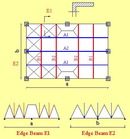
11 Paneled Beam Slab Design of Edge Beams The floor "mother" slab a b is divided into small slabs s 1, s 2, s 3 by a system of paneled beams. Each of the baby slabs s 1, s 2, s 3.. is designed as a solid (or hollow blacks) slab. For the designer of edge beams, consider the whole slab a b to be carried by the four beams at the four edges: For analysis of edge beams, there are two approaches: 1. distribute load on edge beams from slab as if there is no paneled beams inside, i.e. assuming fracture lines at 45 o from corners. this approach becomes more appropriate as the number of paneled beams not supported directly on columns increases.

12 2. Transfer reactions of panelled beams to edge beams and solve the edge beam subjected to: 1. reaction of panelled beams 2. slab loads of slabs adjacent to the edge beam. this approach becomes more appropriate than the former one as the number of panelled beams supported directly on column increases.
13
14 Flat Slabs Introduction Flat slabs are beamless slabs resting directly on columns. They may have drop panels and/ or columns may have column capitals as shown in Figure (1). They may be solid or ribbed in two directions with or without hollow blocks. Generally speaking, flat slabs behave like two continuous orthogonal frame system. Accordingly, the bigger moments occur in the direction of bigger spans. This behavior is different than twoway solid slabs supported on all four sides. Flat slabs Roofs Solid Slabs Flat Slabs
15 Flat Slabs without drop Panel B ( L.L 500 kg/cm2) A A t s B Section A - A Flat slabs with drop Panel ( L.L 1000 kg/cm2) A A t s (drop panel) t s Section A - A
16

17 Flat Slabs

18

19 o Stairs Slab and Beam Type Slab Type Cantilever Type Cantilever Type
20 Solid Slabs ne Way Slabs Effective Span Loads Minimum Thickness Bending Moments Reinforcement Supports O Two Way Slabs General Effective Spans Minimum Thickness Simplified Method for Calculating B.M. in Two Way Slabs Reinforcement Calculations Practical Cases Concluding Remarks
21 Waffled slabs (ribbed slabs without hollow blocks, spacing about 1 m each direction) Solid Slabs Hollow Block Slabs Flat Slabs Waffle Slabs Paneled Beams Slabs Loads Spans Design Requirements Ly Structural system must be chosen to satisfy economic requirements according to these factors Lx
22 One-way slabs Thickness t = b / 30 = b / 35 = b / 40 = b / 10 Two-way slabs Thickness t = b / 35 = b / 40 = b / 45
23
")

24 One Way Slabs * Slabs supported on two opposite sides only * Slabs supported on four sides with effective length (b e ) greater than twice the effective length (ae) * One way slabs are to be calculated based on strips of unit length in the short direction

 Continuous or simply")

25 Effective Span i) L e for simple or continues slab is the larger of : or or c s 1.05 L c L e < L ii) L e for cantilever slabs is the smaller of : L or L c + t s iii) Continuous or simply supported slabs supported on beams with b > 0.2 L c can be designed as fixed at support, and every span can be calculated separately
26 Loads * Total load on slab: W = W D + W L * Dead loads: W D = slab self weight + flooring = t s (mm) ( ) kn/m 2 * Live loads: W L : depends on the function of the building. * If designing using Limit State Design Method, use W u = 1.4 W D W L L.L IS TO BE TAKEN FROM FROM CODE ACCORDING TO THE FUNCTION OF THE BUILDING Supports The width of the support for slab is the larger of : ts or 150 mm..for brick walls 100 mm for R.C. beams

27 Minimum Thickness 1. Slab thickness shall not be less than the absolute minimum of: t min = L e /30 simply supported at both ends t min = L e /35 continuous at one end tmin = Le/40 continuous at both ends Where L e is the effective span as defined above 2. For ordinary buildings and cast-in-situ slabs: t s > 80 mm under static loads t s > 120 mm under dynamic loads 3. Smaller thicknesses can be used in pre-cast slabs. 4. Minimum thickness to satisfy the deflection limits in ordinary buildings (i.e. no need to check deflection if the slab thickness is not less than the values indicated) is as follows: Table (4-10) ECCS Span / depth ratio; L/d * Table (4-10) applies only if the following conditions are satisfied: 1. ordinary buildings 2. spans 10 m 3. uniform, but not heavy, live load, (live load twice dead load)

28 Bending Moments N.B. * In designing with Ultimate Limit States Design Method: w = w ultimate * In designing with Working Stress Design Method: w = w working
29
30
31

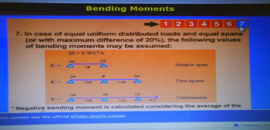
32 Bending moment of slab According to ECCS , the bending moment of equal span ribs or with maximum difference not greater than 20% of the larger span is as follows: M = wl 2 /k, where k is as follows: - Simple span - Two spans - More than two spans Reinforcement The main reinforcement of a slab shall satisfy the requirements of equilibrium: C = T M u = C. y ct = T. y ct cover = mm The reinforcement shall also be arranged along the direction of short span.normal to the main reinforcement, shrinkage and temperature (distributes) reinforcement are provided.
33 1. Minimum main reinforcement: * For mild steel : * For high strength steel : The main reinforcement should be arranged to cover all the tension zones and extend beyond the end of these zones enough to develop the necessary anchorage.
34 One way slab reinforcement details. 3. Maximum spacing between bars of main steel is 2 t s and < 200 mm. For ts < 100 mm, spacing of 200 mm may be used. 4. A minimum of 1/3 of the main steel must be extended to the supports. 5. Distributors with minimum of 4 bars/m. 6. Minimum diameter for straight bars is 6 mm. Minimum diameter for bent bars is 8 mm. Bars of smaller diameters may be used for welded wire mesh and pre-cast concrete. 7. When using steel mesh, all conditions above must be satisfied.
35 8. For slabs with thicknesses 160 mm, top mesh must be provided. The top mesh must be taken 20% of the bottom reinforcement, but not less than 5Ø8 /m' for mild steel or 5Ø6 /m' for high strength steel. Choice of Slab Reinforcement 1. Chosen bars diameters: - mild steel (24/35) 8, 10, 13mm - high grade steel(36/52) 8, 10, 12mm 2. Half of the steel is straight bars & the other half is bent bars 3. Min. number of bars (in 1.0 m) is 5 and max. number is 10, the common number is 6 8 ( 6 10/m ) 4. We can use bars of the same diameters or two successive diameters ( /m ) and the big diam is the bent bar 5. The number of bars should be the same in the same direction 6. Steel in long direction (secondary) 0.25 steel in short direction (main) 7. Rules of bent bars in beams ( L / 7, L / 5, L / 4) are applied for slabs
36 Practical Cases 1- In one way slab, difference between adjacent spans is greater than 20%: - Solve continuous strip (1.0 m width) 2- One way slab adjacent to two way slab: - Design for the larger ve moment at the common support 3- Washrooms: - Drop slab of the washrooms by ( ) mm. Hence slabs become not continuous with adjacent slab of the floor. 4- Slab with openings: - For small openings less than spacing between bars; do nothing. - For small openings greater than spacing between bars; use additional reinforcement.
37 * For large openings, use more accurate analysis.

38 Two Way Slabs Two-way slabs Thickness t = b / 35 = b / 40 = b / 45


39 Two Way Slabs - A small element of medium thick plate is shown in figure:
40 The following equation gives the basic equilibrium requirement for a medium thick plate: Unlike one way slabs which deform under load into nearly a cylindrical surface, two way slabs bend into a dished surface. This means that at any point, the slab is curved in both directions. The applied distributed load W on the element is carried partly by bending as a beam strip in the x- direction producing M x, partly by bending of the strip in the y-direction producing M y, and the remainder by interaction between the x and y strips, i.e. by torsion producing M xy. General 1. Rectangular slabs supported on all four sides can be considered as two way slabs if the rectangularity ratio r is smaller than 2, or large than Slabs can be solved according to the elastic theories on condition that the reinforcement resisting ve moments is placed in the right position during casting.. 3. The following method of design is valid only for ordinary buildings with small uniformly distributed live load up to 5 kn/m 2.
41 Loads * Total load on slab: W = W D + W L * Dead loads: W D = slab self weight + flooring = t s (mm) ( ) kn/m 2 * Live loads: W L : depends on the function of the building. * If designing using Limit State Design Method, use W u = 1.4 W D W L L.L IS TO BE TAKEN FROM FROM CODE ACCORDING TO THE FUNCTION OF THE BUILDING Supports The width of the support for slab is the larger of : ts or 150 mm..for brick walls 100 mm for R.C. beams Effective Spans - Refer to one way slabs.
42 Minimum Thickness 1. Slab thickness shall not be less than the absolute minimum of: t min = L e /35 for freely supported slab tmin = Le/40 for slab continuous at one end tmin = Le/45 for continuous or fixed slab Where L e = the smaller effective span of the slab as indicated in one way slabs.

43 Simplified Method for Calculating B.M. in Two Way Slabs Rectangular slabs, monolithically cast with beams and supported on all four sides, with rectangularity ratio r less than 2 and greater than 0.5 subjected to uniform loads can be calculated according to the following simplified method: where: m b = ratio of length between points of inflection for a loaded strip in direction of span b to the effective span b. m a = same but for span a a = the effective span in direction a. b = the effective span in direction b. The values of m a & m b are to be determined from theory of elasticity. For slabs, the following values may be adopted. Knowing the value of r, the load carried in each of the two perpendicular directions can be calculated using the values of α and β of Table (6-1) (ECCS ) Table (6-1) EC 2001 For slabs monolithically cast with beams α = 0.5r 0.15 β = 0.35/r 2

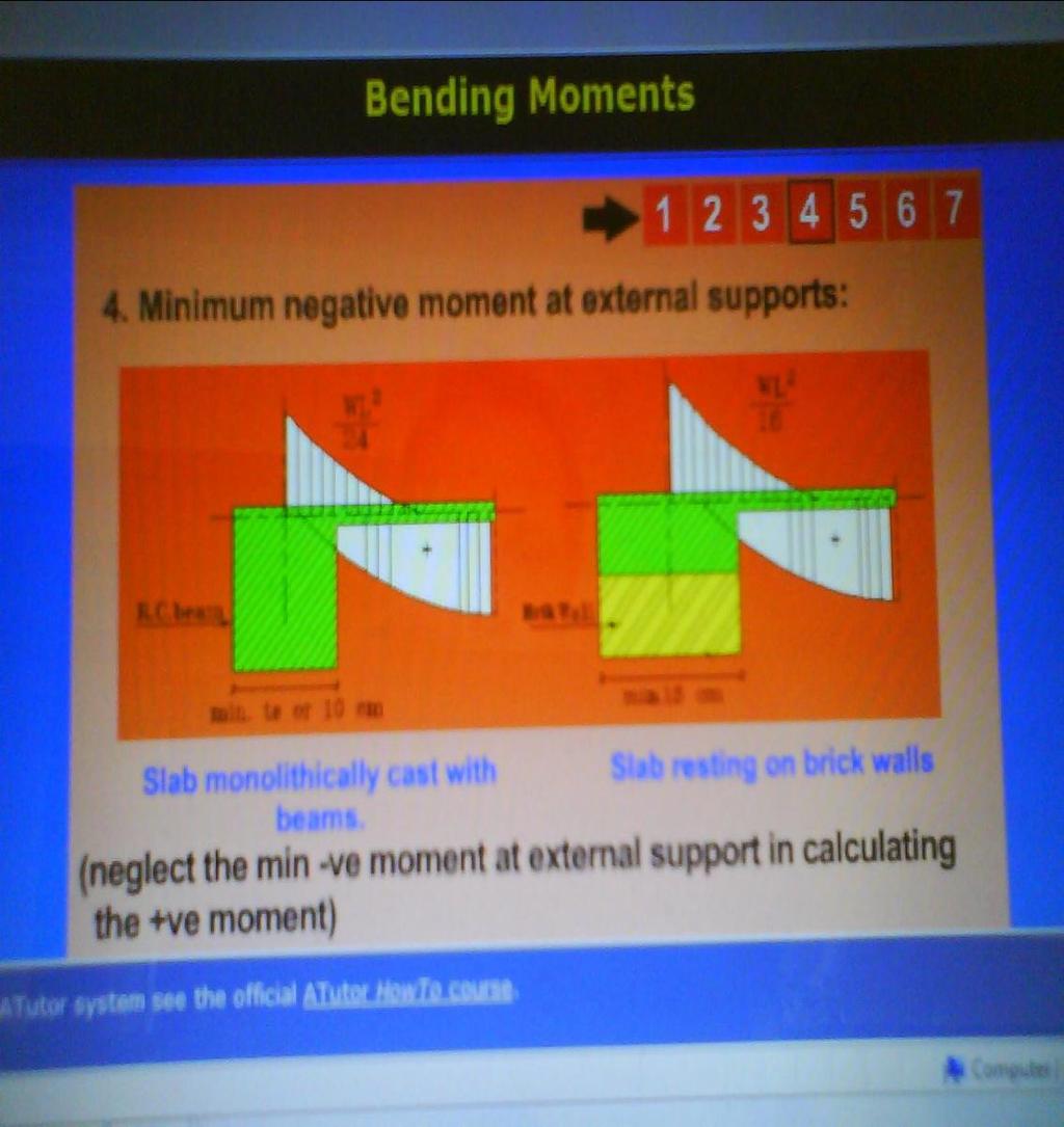
 (ECCS 203-2001) For slabs resting on masonry walls * If live load 500 kg/m 2, use Table (6-3) instead of Tables (6-1) and (6-2).")
44 The bending moment in continuous slabs can be calculated as follows: where: k = 10 for slabs continuous at one end. = 12 for slabs continuous at both ends. N.B.: negative moment of at exterior support must be considered. For slabs resting on masonry walls, the load distribution factors, α and β are determined according to Table (6-2) ECCS Table (6-2) (ECCS ) For slabs resting on masonry walls * If live load 500 kg/m 2, use Table (6-3) instead of Tables (6-1) and (6-2). Table (6-3) (ECCS ) For solid slabs resting with L.L. 500 kg/m 2

45 Two-way slabs Thickness t = b / 35 = b / 40 = b / 45
46 1. Loadings : * Dead Load (w D ) - concrete weight : 0.12 x 2500 kg/m 2 - flooring kg/m 2 * Live Load (w L ) = according to building type * Total slab load : w s = w D + w L 2. Load distribution according to Code : * distribution factor 1 r 2 * continuity factor m r = m1 * L1 m = 1.00 m2 * L2 m = 0.87 m = 0.76 The loads in each direction are as: For two way slabs w = w s ---- short direction w = w s ---- long direction Using r ---- Get, from Code table (6-1)..page(5) in the curves For one way slabs w = w s w = 0.0
47 3. bending moments in slabs M = M = M = M = w L 2 8 w L 2 10 w L 2 12 w L Design of sections d short = t s 1.5 cm d long = t s 2.5 cm d long d short t
48 Reinforcement The main reinforcement of a slab shall satisfy the requirements of equilibrium : C = T M u = C. y ct = T. y ct cover = mm The reinforcement shall also be arranged along the direction of short span.normal to the main reinforcement, shrinkage and temperature (distributes) reinforcement are provided. 1. Minimum main reinforcement: * For mild steel : * For high strength steel : nd2. The main reinforcement should be arranged to cover all the tension zones a extend beyond the end of these zones enough to develop the necessary anchorage.
49 EACH DIRECTIN OF X AND Y One way slab reinforcement details. 3. Maximum spacing between bars of main steel is 2 t s and < 200 mm. For ts < 100 mm, spacing of 200 mm may be used. 4. A minimum of 1/3 of the main steel must be extended to the supports. 5. Minimum diameter for straight bars is 6 mm. Minimum diameter for bent bars is 8 mm. Bars of smaller diameters may be used for welded wire mesh and pre-cast concrete. 6. When using steel mesh, all conditions above must be satisfied. 7. For slabs with thicknesses 160 mm, top mesh must be provided. The top mesh must be taken 20% of the bottom reinforcement, but not less than 5Ø8 /m' for mild steel or 5Ø6 /m' for high strength steel.
50 Reinforcement 1. Maximum spacing of main reinforcement in the middle zone of the span is 2ts but not more than 200 mm. However, For ts < 100 mm, 5 bars/m may be used. 2. Reinforcement in the secondary direction should not be less than 0.25 of the main reinforcement with minimum of 5 bars/m'. 3. Positive reinforcement adjacent and parallel to a continuous edge may be reduced by 25% for a width of not more than ¼ the shorter span of the panel. 4. For other details, refer to one way slabs.
51 Choice of Slab Reinforcement 1. Chosen bars diameters: - mild steel (24/35) 8, 10, 13mm - high grade steel(36/52) 8, 10, 12mm 2. Half of the steel is straight bars & the other half is bent bars 3. Min. number of bars (in 1.0 m) is 5 and max. number is 10, the common number is 6 8 ( 6 10/m ) 4. We can use bars of the same diameters or two successive diameters ( /m ) and the big diam is the bent bar 5. The number of bars should be the same in the same direction 6. Steel in long direction (secondary) 0.25 steel in short direction (main) 7. Rules of bent bars in beams ( L / 7, L / 5, L / 4) are applied for slabs ANALYSIS AND DESIGN APPROACHE: - TAKING STRIPS IN BOTH DIRECTION X & Y - USING DESIGN TABLES

 a table in the following form may be")
52 Calculations Calculations may be carried out in a table form as follows: 1. Load distribution 2. Bending moment and reinforcement For each direction (i.e. main and secondary directions) a table in the following form may be used. i) For short direction
53 Slab Reinforcement L / (2.5 10/m) (2.5 10/m) ( L / 7 L / 5 L Slab Reinforcement 1.5 L ( / m ) Main reinforcement ( ) Cantilever Slab Secondary reinforcement ( T & B )
54 Practical Cases 1- In one way slab, difference between adjacent spans is greater than 20%: - Solve continuous strip (1.0 m width) 2- One way slab adjacent to two way slab: - Design for the larger ve moment at the common support 3- Washrooms: - Drop slab of the washrooms by ( ) mm. Hence slabs become not continuous with adjacent slab of the floor. 4- Slab with openings: - For small openings less than spacing between bars; do nothing. - For small openings greater than spacing between bars; use additional reinforcement.
55 * For large openings, use more accurate analysis.
56 Solid Slabs Hollow Block Slabs Flat Slabs Waffle Slabs Paneled Beams Slabs Loads Spans Design Requirements Ly Structural system must be chosen to satisfy economic requirements according to these factors Lx
57 One-way slabs Thickness t = b / 30 = b / 35 = b / 40 = b / 10 Two-way slabs Thickness t = b / 35 = b / 40 = b / 45
58 1. Loadings : * Dead Load (w D ) - concrete weight : 0.12 x 2500 kg/m 2 - flooring kg/m 2 * Live Load (w L ) = according to building type * Total slab load : w s = w D + w L 2. Load distribution according to Code : * distribution factor 1 r 2 * continuity factor m r = m1 * L1 m = 1.00 m2 * L2 m = 0.87 m = 0.76 The loads in each direction are as: For two way slabs w = w s ---- short direction w = w s ---- long direction Using r ---- Get, from Code table (6-1)..page(5) in the curves For one way slabs w = w s w = 0.0
59 3. bending moments in slabs M = M = M = M = w L 2 8 w L 2 10 w L 2 12 w L Design of sections d short = t s 1.5 cm d long = t s 2.5 cm d long d short t

60 Slab l effx w x t/m M x d cm R a s A s chosen /m cm 2 /m 5 8/m S1 3 8/m+3 10/m S2 6 8/m S3 x- direc. 6 8/m 6 10/m S4 S5 3 10/m+3 13/m S6 6 13/m S7 6 10/m S8 Slab l effx w x t/m M y d (cm) R A s cm 2 /m A s chosen /m S /m S /m++3 10/m y- direc. S /m S /m S /m S /m S /m S /m+3 13/m
61 Choice of Slab Reinforcement 1. Chosen bars diameters: - mild steel (24/35) 8, 10, 13mm - high grade steel(36/52) 8, 10, 12mm 2. Half of the steel is straight bars & the other half is bent bars 3. Min. number of bars (in 1.0 m) is 5 and max. number is 10, the common number is 6 8 ( 6 10/m ) 4. We can use bars of the same diameters or two successive diameters ( /m ) and the big diam is the bent bar 5. The number of bars should be the same in the same direction 6. Steel in long direction (secondary) 0.25 steel in short direction (main) 7. Rules of bent bars in beams ( L / 7, L / 5, L / 4) are applied for slabs
62 Slab Reinforcement L / (2.5 10/m) (2.5 10/m) L / 7 L / 5 L
63 Slab Reinforcement 1.5 L ( / m ) Main reinforcement ( ) Cantilever Slab Secondary reinforcement ( T & B )
64

65 Final Reinforcement of Slab
66
DESIGN OF SLABS. 3) Based on support or boundary condition: Simply supported, Cantilever slab,
 Based on support or boundary condition: Simply supported, Cantilever slab,") DESIGN OF SLABS Dr. G. P. Chandradhara Professor of Civil Engineering S. J. College of Engineering Mysore 1. GENERAL A slab is a flat two dimensional planar structural element having thickness small compared
DESIGN OF SLABS Dr. G. P. Chandradhara Professor of Civil Engineering S. J. College of Engineering Mysore 1. GENERAL A slab is a flat two dimensional planar structural element having thickness small compared
Design of Reinforced Concrete Slabs
 Lecture 07 Design of Reinforced Concrete Slabs By: Prof Dr. Qaisar Ali Civil Engineering Department UET Peshawar drqaisarali@uetpeshawar.edu.pk 1 Topics Addressed Introduction Analysis and Design of slabs
Comparison of One-way and Two-way slab behavior. One-way slabs carry load in one direction. Two-way slabs carry load in two directions.
 Two-way Slabs Comparison of One-way and Two-way slab behavior One-way slabs carry load in one direction. Two-way slabs carry load in two directions. Comparison of One-way and Two-way slab behavior One-way
eight plates and grids APPLIED ACHITECTURAL STRUCTURES: DR. ANNE NICHOLS SPRING 2018 lecture STRUCTURAL ANALYSIS AND SYSTEMS ARCH 631
 APPLIED ACHITECTURAL STRUCTURES: STRUCTURAL ANALYSIS AND SYSTEMS DR. ANNE NICHOLS SPRING 2018 lecture eight plates and grids Plates & Grids 1 http://nisee.berkeley.edu/godden Term Project Plates & Grids
eight plates and grids Plates, Slabs & Grids Plates, Slabs & Grids Term Project plates horizontal plane, rigid slabs thin, flat, rigid
 APPLIED ARCHITECTURAL STRUCTURES: STRUCTURAL ANALYSIS AND SYSTEMS DR. ANNE NICHOLS SPRING 2018 Term Project lecture eight plates and grids Plates & Grids 1 Lecture 8 Applied Architectural Structures F2009abn
VARIOUS TYPES OF SLABS
 VARIOUS TYPES OF SLABS 1 CHOICE OF TYPE OF SLAB FLOOR The choice of type of slab for a particular floor depends on many factors. Economy of construction is obviously an important consideration, but this
Sabah Shawkat Cabinet of Structural Engineering 2017
 3.1-1 Continuous beams Every building, whether it is large or small, must have a structural system capable of carrying all kinds of loads - vertical, horizontal, temperature, etc. In principle, the entire
From Park and Gamble Book.
 From Park and Gamble Book. 1 3 4 5 Behavior of Two-Way Slabs Figure 1. Two-Way Slab on Simple Edge Supports: (a) Bending of Center Strips of Slab and (b) Grid Model of Two-Way Slab. Figure 1(a) 5wl 5wl
Pro-Con Structural Study for Alternative Floor Systems October 27, 2004
 Ismail Al-Hadhrami Structural Option Faculty Consultant: Dr. Thomas Boothby Agricultural Hall and Annex East Lansing, MI Pro-Con Structural Study for Alternative Floor Systems October 27, 2004 Executive
Lecture-06 Analysis and Design of Slab Systems
 Lecture-06 Analysis and Design of Slab Systems By: Prof Dr. Qaisar Ali Civil Engineering Department UET Peshawar drqaisarali@uetpeshawar.edu.pk www.drqaisarali.com 1 Topics Addressed Organization of the
Two-way slabs. Flat plate with or without drop panels / capitals
 Two-way slabs Two-way slab behavior is described by plate bending theory which is a complex extension of beam bending. Codes of practice allow use of simplified methods for analysis and design of two-way
mortarless masonry Design Manual Part 1 (IS 456:2000) Section 1 Page 1 IS 456:2000 PLAIN AND REINFORCED CONCRETE - CODE OF PRACTICE
 Section 1 Page 1 IS 456:2000 PLAIN AND REINFORCED CONCRETE - CODE OF PRACTICE") SECTION 1. mortarless masonry Design Manual Part 1 (IS 456:2000) Section 1 Page 1 1.1 Overview of IS 456:2000 IS 456:2000 PLAIN AND REINFORCED CONCRETE - CODE OF PRACTICE IS 456:2000 is the current Indian
SECTION 1. mortarless masonry Design Manual Part 1 (IS 456:2000) Section 1 Page 1 1.1 Overview of IS 456:2000 IS 456:2000 PLAIN AND REINFORCED CONCRETE - CODE OF PRACTICE IS 456:2000 is the current Indian
Flat Slabs. d 2. A typical flat slab (without drop and column head)
") 1 CHAPTER Flat Slabs 1.1 INTRDUCTIN Common practice of design and construction is to support the slabs by beams and support the beams by columns. This may be called as beam-slab construction. The beams
1 CHAPTER Flat Slabs 1.1 INTRDUCTIN Common practice of design and construction is to support the slabs by beams and support the beams by columns. This may be called as beam-slab construction. The beams
SIDDHARTH GROUP OF INSTITUTIONS :: PUTTUR Siddharth Nagar, Narayanavanam Road QUESTION BANK (DESCRIPTIVE)
") SIDDHARTH GROUP OF INSTITUTIONS :: PUTTUR Siddharth Nagar, Narayanavanam Road 517583 QUESTION BANK (DESCRIPTIVE) Subject with Code : DDRCS(13A01502) Year & Sem: III-B.Tech & I-Sem Course & Branch: B.Tech
SIDDHARTH GROUP OF INSTITUTIONS :: PUTTUR Siddharth Nagar, Narayanavanam Road 517583 QUESTION BANK (DESCRIPTIVE) Subject with Code : DDRCS(13A01502) Year & Sem: III-B.Tech & I-Sem Course & Branch: B.Tech
Section A A: Slab & Beam Elevation
 CE 331, Spring 2011 Flexure Strength of Reinforced Concrete s 1 / 5 A typical reinforced concrete floor system is shown in the sketches below. The floor is supported by the beams, which in turn are supported
Analysis and Design of One-way Slab System (Part-I)
") Lecture-02 Analysis and Design of One-way Slab System (Part-I) By: Prof Dr. Qaisar Ali Civil Engineering Department UET Peshawar www.drqaisarali.com 1 Topics Addressed Concrete Floor Systems Analysis and
Lecture-02 Analysis and Design of One-way Slab System (Part-I) By: Prof Dr. Qaisar Ali Civil Engineering Department UET Peshawar www.drqaisarali.com 1 Topics Addressed Concrete Floor Systems Analysis and
Structural System. Design Criteria Fire Resistance Concrete designed for 2 HR rating (worst case) Geotechnical Report Allowable Bearing Capacity
 Geotechnical Report Allowable Bearing Capacity") System Codes and Criteria Design Codes and Standards The design code used is the Wisconsin Administrative Code along with the State of Wisconsin Department of Commerce-Safety & Buildings Chapters Comm
System Codes and Criteria Design Codes and Standards The design code used is the Wisconsin Administrative Code along with the State of Wisconsin Department of Commerce-Safety & Buildings Chapters Comm
Figure: Grid or Waffle slab
 Two Way Beam Supported Slab References: 1. Design of. Reinforced Concrete, 2014, 9 th Edition, ACI 318-11 Code Edition, by Jack C. McCormac. Clemson University. Russell H. Brown. Clemson University 2.
EGCE 406: Bridge Design
 EGCE 406: Bridge Design Design of Slab for Praveen Chompreda Mahidol University First Semester, 2006 Bridge Superstructure Outline Components of bridge Superstructure Types Materials Design of RC Deck
2016 DESIGN AND DRAWING OF REINFORCED CONCRETE STRUCTURES
 R13 SET - 1 DESIGN AND DRAWING OF REINFCED CONCRETE STRUCTURES 1 Design a simply supported rectangular beam to carry 30kN/m superimposed load over a span of 6m on 460mm wide supports. Use M20 grade concrete
DIRECT DESIGN METHOD DDM
 DIRECT DESIGN METHOD DDM Load Transfer Path For Gravity Loads All gravity loads are basically Volume Loads generated due to mass contained in a volume Mechanism and path must be found to transfer these
VTU EDUSAT PROGRAMME Lecture Notes on Design of Stair cases
 VTU EDUSAT PROGRAMME 17 2012 Lecture Notes on Design of Stair cases DESIGN OF RCC STRUCTURAL ELEMENTS - 10CV52 (PART B, UNIT 8) Dr. M. C. Nataraja Professor, Civil Engineering Department, Sri Jayachamarajendra
UNIT-I DESIGN CONCEPTS, DESIGN OF BEAMS Part - A (Short Answer Questions)
") S.NO IMPORTANT QUESTIONS UNIT-I DESIGN CONCEPTS, DESIGN OF BEAMS Part - A (Short Answer Questions) 1 What are the three methods of design of reinforced concrete structural elements? 2 State four objectives
S.NO IMPORTANT QUESTIONS UNIT-I DESIGN CONCEPTS, DESIGN OF BEAMS Part - A (Short Answer Questions) 1 What are the three methods of design of reinforced concrete structural elements? 2 State four objectives
CE2306 DESIGN OF RC ELEMENTS UNIT II LIMIT STATE DESIGN FOR FLEXTURE Part A (2marks) 1. Explain the check for deflection control in the design of
 1. Explain the check for deflection control in the design of") CE2306 DESIGN OF RC ELEMENTS UNIT II LIMIT STATE DESIGN FOR FLEXTURE Part A (2marks) 1. Explain the check for deflection control in the design of slabs? (NOV-DEC 2012) The deflection of a structure or
CE2306 DESIGN OF RC ELEMENTS UNIT II LIMIT STATE DESIGN FOR FLEXTURE Part A (2marks) 1. Explain the check for deflection control in the design of slabs? (NOV-DEC 2012) The deflection of a structure or
Module Title: Advanced Structural Design
 CORK INSTITUTE OF TECHNOLOGY INSTITIÚID TEICNEOLAÍOCHTA CHORCAÍ Semester 1 Examinations 2008/09 Module Title: Advanced Structural Design Module Code: CIVL 8001 School: Building & Civil Engineering Programme
DESIGN OF RC ELEMENTS UNIT 1 PART-A
 DESIGN OF RC ELEMENTS UNIT 1 PART-A 1. Calculate the design strength for M 30 grade concrete and Fe 415 grade steel? 2. What is the important principle of ultimate load method? 3. Write the classification
Reinforced Concrete Design. Lecture no. 1
 Reinforced Concrete Design Lecture no. 1 Mechanics of RC Concrete is strong in compression but week in tension. Therefore, steel bars in RC members resist the tension forces. RC Members Reinforced concrete
twenty two concrete construction: flat spanning systems, columns & frames ARCHITECTURAL STRUCTURES: FORM, BEHAVIOR, AND DESIGN
 ARCHITECTURAL STRUCTURES: FORM, BEHAVIOR, AND DESIGN DR. ANNE NICHOLS SUMMER 2014 lecture twenty two concrete construction: http:// nisee.berkeley.edu/godden flat spanning systems, columns & frames Concrete
twenty two concrete construction: flat spanning systems, columns & frames Reinforced Concrete Design Reinforced Concrete Design
 ARCHITECTURAL STRUCTURES: FORM, BEHAVIOR, AND DESIGN DR. ANNE NICHOLS SUMMER 2013 lecture twenty two economical & common resist lateral loads concrete construction: flat spanning systems, columns & frames
Class Topics & Objectives
 EGCE 406: Bridge Design Design of Slab for Bridge Deck Praveen Chompreda, Ph.D. Mahidol University First Semester, 2010 Class Topics & Objectives Topics Objective Bridge Superstructures Students can identify
Agricultural Hall and Annex East Lansing, MI. Structural Design. Gravity Loads. 1- Based on US Standards
 Structural Design Gravity Loads 1- Based on US Standards Occupancy or Use Uniform (psf) Concentrated (lbs) Office building -Office -Lobbies and first-floor corridors -Corridor above first floor -Partitions
twenty two concrete construction: flat spanning systems, columns & frames Reinforced Concrete Design Reinforced Concrete Design
 ARCHITECTURAL STRUCTURES: FORM, BEHAVIOR, AND DESIGN DR. ANNE NICHOLS SUMMER 2014 lecture twenty two economical & common resist lateral loads concrete construction: flat spanning systems, columns & frames
Types of Foundations
 Shallow Foundations Types of Foundations Foundations can be classified to two major categories: Shallow. Deep. 1 Introduction If the soil stratum is suitable for supporting the structural loads from the
THE FORENSIC MEDICAL CENTER
 THE FORENSIC MEDICAL CENTER Image courtesy of Gaudreau, Inc. TECHNICAL REPORT #2 OCTOBER 26, 2007 KEENAN YOHE STRUCTURAL OPTION DR. MEMARI FACULTY ADVISOR EXECUTIVE SUMMARY Image courtesy of Gaudreau,
UNIT IVCOMPOSITE CONSTRUCTION PART A
 UNIT IVCOMPOSITE CONSTRUCTION PART A 1. What is composite section of pestressed concrete? [A/M 16] A composite section in context of prestressed concrete members refers to a section with a precast member
Continuous Beam Design with Moment Redistribution (CSA A )
") Continuous Beam Design with Moment Redistribution (CSA A23.3-14) Continuous Beam Design with Moment Redistribution (CSA A23.3-14) A structural reinforced concrete continuous beam at an intermediate floor
Continuous Beam Design with Moment Redistribution (CSA A23.3-14) Continuous Beam Design with Moment Redistribution (CSA A23.3-14) A structural reinforced concrete continuous beam at an intermediate floor
William W. Wilkins Professional Building
 STRUCTURAL REDESIGN The alternate structural system evaluated is a one-way slab with reinforced concrete skip-joists. The alternate lateral system investigated is reinforced concrete moment frames. Skip-joists
ANALYTICAL STUDY OF PUNCHING SHEAR ON WAFFLE SLAB WITH DIFFERENT RIB SIZES
 Jr. of Industrial Pollution Control 33(S2)(27) pp 323-327 www.icontrolpollution.com Research Article ANALYTICAL STUDY OF PUNCHING SHEAR ON WAFFLE SLAB WITH DIFFERENT RIB SIZES K. SAKETH*, C. ARUNKUMAR
ANALYSIS AND DESIGN OF REGULAR AND IRREGULAR FLAT SLAB FOR MULTISTOREYED BUILDING UNDER TWO SEISMIC ZONES USING ETABS AND SAFE
 ANALYSIS AND DESIGN OF REGULAR AND IRREGULAR FLAT SLAB FOR MULTISTOREYED BUILDING UNDER TWO SEISMIC ZONES USING ETABS AND SAFE THIMMAYAPALLY DILEEP KUMAR 1, A.MOWNIKA VARDHAN 2 1 M. Tech (Structural Engineering),
Strength Design of Reinforced Concrete Structures
 Chapter 6 Strength Design of Reinforced Concrete Structures 6.1 Analysis and Design General Considerations 6.1.1 Convention and Notation Unless otherwise explicitly stated, the following units shall be
Slabs and Flat Slabs
 Slabs and Flat Slabs Lecture 5 19 th October 2017 Contents Lecture 5 Designing for shear in slabs - including punching shear Detailing Solid slabs Flat Slab Design includes flexure worked example Exercise
Applications of sustainable post-tensioned concrete slabs
 Innov. Infrastruct. Solut. (2017) 2:42 DOI 10.1007/s41062-017-0075-6 TECHNICAL PAPER Applications of sustainable post-tensioned concrete slabs Amr A. Abdelrahman 1 Received: 4 May 2017 / Accepted: 2 June
UNIT-1 RETAINING WALLS
 UNIT-1 RETAINING WALLS PART-A 1. Describe about Retaining wall. 2. Define gravity retaining walls. BT-1 3. Classify the types of retaining walls. 4. Explain cantilever retaining wall? 5. Describe about
Alternate Design Method- Design Procedure of Two-way Slabs using ACI Moment Coefficients and Approved by BNBC 2013
 Alternate Design Method- Design Procedure of Two-way Slabs using ACI Moment Coefficients and Approved by BNBC 2013 Scope and Limitations (BNBC) 6.5.8.2.1 The provisions of this section may be used as alternative
ST7008 PRESTRESSED CONCRETE
 ST7008 PRESTRESSED CONCRETE QUESTION BANK UNIT-I PRINCIPLES OF PRESTRESSING PART-A 1. Define modular ratio. 2. What is meant by creep coefficient? 3. Is the deflection control essential? Discuss. 4. Give
Sabah Shawkat Cabinet of Structural Engineering 2017
 3.3 Staircases Staircases provide means of movement from one floor to another in a structure. The effective span of a simply supported slab should normally be taken as the clear distance between the faces
A Finite Element Approach to Reinforced Concrete Slab Design in GT STRUDL
 A Finite Element Approach to Reinforced Concrete Slab Design in GT STRUDL James Deaton and Dr. Kenneth M. Will 2006 GT STRUDL Users Group Meeting 23 June 2006 1 Introduction Background and Motivation The
How Loads Are Distributed
 LOAD DISTRIBUTION 1 LOAD DISTRIBUTION This section illustrate how load will transmit from the deck to the stringers. Determining the fraction of load carried by a loaded member and the remainder distributed
> 0. 1 f, they are treated as beam-columns.
 223 A- Flexural Members (Beams) of Special Moment Frames Requirements of ACI 21.5 are applicable for special moment frame members proportioned primarily to resist flexure with factored axial forces 0.
One-Way Wide Module Joist Concrete Floor Design
 One-Way Wide Module Joist Concrete Floor Design A 1 3 4 30'-0" 30'-0" 30'-0" 3' B 3' C 3' D 3' E 4" 4" (typ.) 3' F 0" 0" (typ.) Figure 1 One-Way Wide Module Joist Concrete Floor Framing System 1 Overview
Analysis of Shear Wall Transfer Beam Structure LEI KA HOU
 Analysis of Shear Wall Transfer Beam Structure by LEI KA HOU Final Year Project report submitted in partial fulfillment of the requirement of the Degree of Bachelor of Science in Civil Engineering 2013-2014
A Guide for the Interpretation of Structural Design Options for Residential Concrete Structures
 CFA Technical Note: 008-2010 A Guide for the Interpretation of Structural Design Options for Residential Concrete Structures CFA Technical This CFA Technical Note is intended to serve as a guide to assist
Code No: R Set No. 1
 Code No: R059210303 Set No. 1 II B.Tech I Semester Regular Examinations, November 2006 MECHANICS OF SOLIDS ( Common to Mechanical Engineering, Mechatronics, Metallurgy & Material Technology, Production
fourteen Structural Planning 1 APPLIED ACHITECTURAL STRUCTURES: DR. ANNE NICHOLS SPRING 2019 lecture STRUCTURAL ANALYSIS AND SYSTEMS ARCH 631
 APPLIED ACHITECTURAL STRUCTURES: STRUCTURAL ANALYSIS AND SYSTEMS DR. ANNE NICHOLS SPRING 2019 lecture fourteen structural planning Structural Planning 1 Structural Design Sequences first-order design structural
Kaleida Health Global Heart and Vascular Institute University at Buffalo CTRC/Incubator. Buffalo, New York. Technical Report #2
 University at Buffalo CTRC/Incubator Buffalo, New York William McDevitt October 27, 2010 Table of Contents Executive Summary...3 Introduction...4 Structural System Overview...5 Foundation...5 Floor System...5
CHAPTER 2. Design Formulae for Bending
 CHAPTER 2 Design Formulae for Bending Learning Objectives Appreciate the stress-strain properties of concrete and steel for R.C. design Appreciate the derivation of the design formulae for bending Apply
Brent Ellmann Structural Option 200 Minuteman Park, Andover, MA Structural Consultant: Dr. Hanagan
 Brief Building Overview: 200 Minuteman Park stands as a 200,000 square foot Class A office building in Andover, Massachusetts, worth roughly $15,000,000. Although the building has a large square footage,
Effect of Spacing of Grid Beam and its Depth on Peripheral beams in Grid Floor Frame
 Effect of Spacing of Grid Beam and its Depth on Peripheral beams in Grid Floor Frame Prof. Dr. S. A. Halkude Department of Civil Engineering, Walchand Institute of Technology. Solapur, India S. V. Mahamuni
Preliminary design of concrete structures 124SDP1
 124SDP1 1 Content 1 Content...- 1-2 Preliminary design...- 2-2.1 Reinforced concrete slab...- 2-2.2 Reinforced concrete beam...- 3-2.3 Reinforced concrete column...- 4 - Department of Concrete and Masonry
Level 6 Graduate Diploma in Engineering Structural analysis
 9210-111 Level 6 Graduate Diploma in Engineering Structural analysis Sample Paper You should have the following for this examination one answer book non-programmable calculator pen, pencil, ruler, drawing
1 Prepared By:Mr.A.Sathiyamoorthy, M.E., AP/Civil
 UNIVERSITY QUESTIONS PART A UNIT 1: INTRODUCTION THEORY AND BEHAVIOUR 1. List the loss of prestress. 2. Define axial prestressing. 3. What is the need for the use of high strength concrete and tensile
Schöck Isokorb type DXT
 Suitable for continuous floors. It transmits negative moments and positive shear forces with cantilever balconies or positive field moments combined with shear forces. 175 Element arrangement Element configurations
Load Deflection Behaviour of Restrained RC Skew Slabs Using FEM Technique
 Load Deflection Behaviour of Restrained RC Skew s Using FEM Technique Naresh Reddy G N Assistant Professor, School of Civil Engineering, REVA University, Rukmini Knowledge Park, Kattigenahalli, Yelahanka,
THE EFFECT OF BEAMS STIFFNESSES ON THE LOAD DISTRIBUTION IN A SINGLE SIMPLY SUPPORTED TWO-WAY RIBBED SLAB
 The Islamic University Journal (Series of Natural Studies and Engineering) Vol.14, No.1, P.191-208, 2006, ISSN 1726-6807, http//www.iugzaza.edu.ps/ara/research/ THE EFFECT OF BEAMS STIFFNESSES ON THE LOAD
Atkinson Engineering, Inc.
 Atkinson Engineering, Inc. Atkinson Engineering, Inc. One of the problems in underpinning a typical post-tensioned foundation is support for the slab part that spans between the stiffening beams. An example
Dr. NAGY GYÖRGY Tamás Professor
 Dr. NAGY GYÖRGY Tamás Professor E mail: tamas.nagy gyorgy@upt.ro Tel: +40 256 403 935 Web: http://www.ct.upt.ro/users/tamasnagygyorgy/index.htm Office: A219 Dr.ing. Nagy György T. Faculty of Civil Engineering
UHPC Connection of Precast Bridge Deck
 Jan L. Vitek, Metrostav, a.s. and CTU in Prague Jiri Kolisko, CTU in Prague, Klokner Institute David Citek, CTU in Prague, Klokner Institute Stanislav Rehacek, CTU in Prague, Klokner Institute Robert Coufal,
Concrete Cracking. ε ctr = f ctr / E c = 0.6 / 4400 = x 10-3
 Concrete Cracking Concrete is known as a sensitive material for cracking. The code defines concrete modulus of elasticity (E c ) and concrete cracking-limit tensile stress (f ctr ) as: E c = 4400 (f cu
Concrete Framing systems. Design choices. Basic flavors
 Concrete Framing systems Design choices Site Cast Concrete gives a designer a lot of freedom in the design and construction of walls, columns and surface textures. When it comes to spanning, concrete offers
BS EN :2004 EN :2004 (E)
") Contents List 1. General 1.1 Scope 1.1.1 Scope of Eurocode 2 1.1.2 Scope of Part 1-1 of Eurocode 2 1.2 Normative references 1.2.1 General reference standards 1.2.2 Other reference standards 1.3 Assumptions
Contents List 1. General 1.1 Scope 1.1.1 Scope of Eurocode 2 1.1.2 Scope of Part 1-1 of Eurocode 2 1.2 Normative references 1.2.1 General reference standards 1.2.2 Other reference standards 1.3 Assumptions
North Mountain IMS Medical Office Building
 North Mountain IMS Medical Office Building Phoenix, Arizona Michael Hopple Technical Assignment 2 October 29 th, 2007 AE 481W-Senior Thesis The Pennsylvania State University Faculty Adviser: Dr. Ali Memari,
Crossroads at Westfields Building II
 Crossroads at Westfields Building II Chantilly, Va STEPHEN LUMPP Structural option Faculty Consultant: Dr. Andres Lepage Technical Report 2 EXECUTIVE SUMMARY This report is a study of alternate floor systems
Lateral System Analysis and Confirmation Design November 15, 2004
 Jonathan Hill Structural AE Faculty Consultant Dr. Hanagan Lynde and Harry Bradley School of Technology & Trade Milwaukee, Wisconsin Lateral System Analysis and Confirmation Design November 15, 2004 Executive
OXFORD ENGINEERING COLLEGE (NAAC Accredited with B Grade) Department of Civil Engineering LIST OF QUESTIONS
 Department of Civil Engineering LIST OF QUESTIONS") OXFORD ENGINEERING COLLEGE (NAAC Accredited with B Grade) Department of Civil Engineering LIST OF QUESTIONS Year/ Sem. : IV / VII Staff Name : S.LUMINA JUDITH Subject Code : CE 6702 Sub. Name : PRE STRESSED
OXFORD ENGINEERING COLLEGE (NAAC Accredited with B Grade) Department of Civil Engineering LIST OF QUESTIONS Year/ Sem. : IV / VII Staff Name : S.LUMINA JUDITH Subject Code : CE 6702 Sub. Name : PRE STRESSED
CADS A3D MAX. How to model shear walls
 CADS A3D MAX How to model shear walls Modelling shear walls in A3D MAX Introduction and synopsis This paper explains how to model shear walls in A3D MAX using the `wide column rigid arm sub-frame described
DESIGN OF RC BEAMS AND FLOORS, BRACING
 BME Department of Mechanics, Materials and Structures Dr András Draskóczy Lecture 5: DESIGN OF RC BEAMS AND FLOORS, BRACING Design of Reinforced Concrete Structures 1 BEAMS, FLOORS, BRACING CONTENT: BEAMS
USE OF 500 GRADE STEEL IN THE DESIGN OF REINFORCED CONCRETE SLAB. Prof. M. Shafiul Bari, Ph.D Department of Civil Engg., BUET
 1.0 Introduction USE OF 500 GRADE STEEL IN THE DESIGN OF REINFORCED CONCRETE SLAB Prof. M. Shafiul Bari, Ph.D Department of Civil Engg., BUET There is growing interest within the reinforced concrete industry
Lysaght Bondek. Structural steel decking system Design and Construction Manual
 Lysaght Bondek Structural steel decking system Design and Construction Manual Excellent spanning capacities for greater strength and less deflection Acts as permanent formwork with minimal propping and
Continuous Beam Design with Moment Redistribution (ACI )
") Continuous Beam Design with Moment Redistribution (ACI 318-14) Continuous Beam Design with Moment Redistribution (ACI 318-14) A structural reinforced concrete continuous beam at an intermediate floor level
Continuous Beam Design with Moment Redistribution (ACI 318-14) Continuous Beam Design with Moment Redistribution (ACI 318-14) A structural reinforced concrete continuous beam at an intermediate floor level
CIVIL ENGINEERING YEAR QUESTION BANK
 CE 6505-DESIGN OF RC ELEMENTS CIVIL ENGINEERING SEM- V YEAR 2015-16 STAFF NAME: THIVAKAR.S A/P QUESTION BANK Subject Name: DESIGN OF RC ELEMENTS Subject Code: CE6505 PART-A UNIT I 1. What are the advantages
Question Paper Code : 11410
 Reg. No. : Question Paper Code : 11410 B.E./B.Tech. DEGREE EXAMINATION, APRIL/MAY 2011 Fourth Semester Mechanical Engineering ME 2254 STRENGTH OF MATERIALS (Common to Automobile Engineering and Production
CE2401-DESIGN OF REINFORCED CONCRETE AND BRICK MASONRY QUESTION BANK
 CE2401-DESIGN OF REINFORCED CONCRETE AND BRICK MASONRY QUESTION BANK UNIT-1 PART-A 1. What is a Retaining wall? 2. What are the disadvantages of gravity retaining walls? 3. What are the types of retaining
3.4.2 DESIGN CONSIDERATIONS
 3.4.2 DESIGN CONSIDERATIONS Formwork Where Flatdeck sheet is used as formwork, the profile provides resistance to wet concrete (G) and construction loads (Q). Maximum formwork spans given in Section 3.4.4.1
1. INTRODUCTION 1.1 FLAT SLAB. 275 P a g e
 Sandesh D. Bothara, Dr.Valsson Varghese / International Journal of Engineering Research and Applications Dynamic Analysis Of Special Moment Resisting Frame Building With Flat Slab And Grid Slab *Sandesh
Austral Deck Design for Construction Loading. Permanent formwork and Span capability
 Austral Deck Design for Construction Loading Permanent formwork and Span capability Introduction The purpose of this document is to demonstrate the process of designing Austral Deck as formwork complying
PARAMETRIC STUDY ON FLAT SLAB WITH AND WITHOUT COLUMN DROP
 Vol-3 Issue- 7 IJARIIE-ISSN(O)-395-4396 PARAMETRIC STUDY ON FLAT SLAB WITH AND WITHOUT COLUMN DROP Jaydeep Chodvadiya, Vipul Vyas, Dr. G.S. Doiphode 3 PG Scholar of Structural Engineering, Charotar University,
Comparative Study of R.C.C and Steel Concrete Composite Structures
 RESEARCH ARTICLE OPEN ACCESS Comparative Study of R.C.C and Steel Concrete Composite Structures Shweta A. Wagh*, Dr. U. P. Waghe** *(Post Graduate Student in Structural Engineering, Y.C.C.E, Nagpur 441
Alexis Pacella Structural Option Dr. Schneider Lexington II, Washington D.C. Technical Report #2 October 31,
 1 Executive Summary: Pro-Con Structural Study of Alternate Floor Systems is an investigation into possible alternative structural systems for Lexington II in Washington, D.C. For this report, several structural
OVERALL STRUCTURAL SYSTEM
 EXECUTIVE SUMMARY The at the Pittsburgh International Airport, PA, is a 275,000 square foot multi-use building located directly adjacent to the airport s landside terminal. The building consists of an
Structural Behaviour and Detailing
 Unit 22: Structural Behaviour and Detailing Unit code: M/601/1282 QCF level: 4 Credit value: 15 Aim This unit enables learners to understand structural concepts and develop skills to determine properties
Schöck Isokorb type K-HV, K-BH, K-WO, K-WU
 Schöck Isokorb type,,, Schöck Isokorb type Contents Page Schöck Isokorb type -CV35 - connection to a step down balcony 56 Schöck Isokorb type -CV35 - connection to a step up balcony 57 Schöck Isokorb type
Multideck 146. Contents
 Contents Specification and Design 55 Load Tables 57 Fire Performance 60 Sound Attenuation 63 Concrete Volume Savings composite steel deck is optimised to minimise the concrete volumes on longer spans providing
UNIVERSITY OF BOLTON WESTERN INTERNATIONAL COLLEGE FZE. BEng (HONS) CIVIL ENGINEERING SEMESTER ONE EXAMINATION 2018/2019
 CIVIL ENGINEERING SEMESTER ONE EXAMINATION 2018/2019") OCD030 UNIVERSITY OF BOLTON WESTERN INTERNATIONAL COLLEGE FZE BEng (HONS) CIVIL ENGINEERING SEMESTER ONE EXAMINATION 2018/2019 ADVANCED STRUCTURAL ANALYSIS AND DESIGN MODULE NO: CIE6001 Date: Tuesday 8
OCD030 UNIVERSITY OF BOLTON WESTERN INTERNATIONAL COLLEGE FZE BEng (HONS) CIVIL ENGINEERING SEMESTER ONE EXAMINATION 2018/2019 ADVANCED STRUCTURAL ANALYSIS AND DESIGN MODULE NO: CIE6001 Date: Tuesday 8
REINFORCED CONCRETE DESIGN
 REINFORCED CONCRETE DESIGN Other Macmillan titles of related interest Microcomputer Applications in Structural Engineering W. H. Mosley and W. J. Spencer Reinforced Concrete Design by Computer R. Hulse
Reinforced Concrete Design. A Fundamental Approach - Fifth Edition
 CHAPTER REINFORCED CONCRETE Reinforced Concrete Design A Fundamental Approach - Fifth Edition Fifth Edition REINFORCED CONCRETE A. J. Clark School of Engineering Department of Civil and Environmental Engineering
Identifying The Problem
 FLEXURAL DESIGN, _~ê= development, hooked bars UNIVERSITY OF WISCONSIN STOUT COLLEGE OF SCIENCE, TECHNOLOGY, ENGINEERING, AND MATHEMATICS LECTURE IV Dr. Jason E. Charalambides = = Identifying The Problem
Cork Institute of Technology. Summer 2006 Structural Design & Detailing I (Time: 4 Hours)
") Cork Institute of Technology Bachelor of Engineering (Honours) in Structural Engineering Stage 2 (NFQ Level 8) Summer 2006 Structural Design & Detailing I (Time: 4 Hours) Instructions: 1. The examination
Cork Institute of Technology Bachelor of Engineering (Honours) in Structural Engineering Stage 2 (NFQ Level 8) Summer 2006 Structural Design & Detailing I (Time: 4 Hours) Instructions: 1. The examination