Precast Concrete Engineering
|
|
|
- Eleanore Barker
- 6 years ago
- Views:
Transcription


1 Precast Concrete Engineering


2 Begin & End On Time! Information Exchange Not Painful PDH s Earned!
3

4 Why Design with Precast? Stand out amongst Owners & Contractors Become known for providing VALUE in that others do not
5 What Value? Increased Durability Reduced Disruption & Downtime Improved Safety More Reliable Time of Completion Less Dependence on Plant Labor

6 Precast Utility Structures Design and Installation

7 Outline Introduction Specifying Design Shipping, Handling and Installation Wrap-Up

8 Outline QUESTION How many of you have specified or been a part of the design or installation of precast concrete utility structures?

9 Introduction Utility Structures encompass a wide variety of precast concrete products Electrical Utilities Gas Utilities Water/Wastewater Emerging Technologies Telecommunications
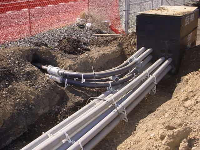
10 Applications
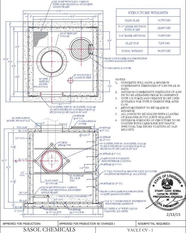
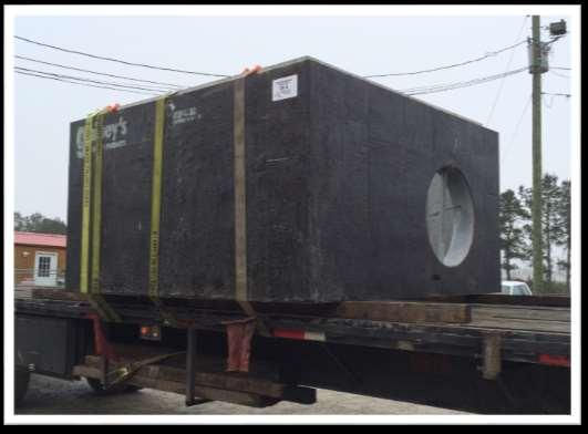
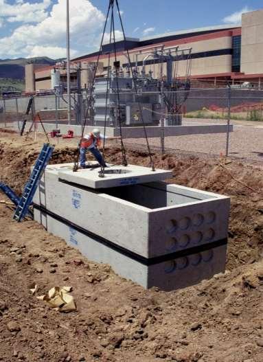
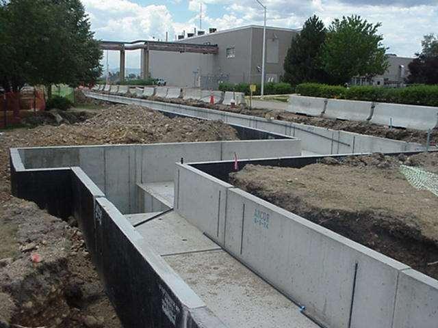
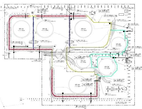
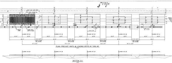
11 Applications Sasol Steam Vaults
12 Applications

13 Applications
14 Applications

15 Applications


16 Applications Renewable Energy


17 Precast Concrete Utility Structures Stock Items Many precasters stock various size items that are made to industry standards. Non-Stock Items Custom utility structures can be made in unlimited sizes and shapes for a project.

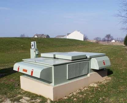
18 Project Solutions

19 Project Solutions


20 Project Solutions
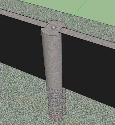
21 Types of Precast Utility Structures Square, Round or Rectangular Vaults Pole Bases Transformer pads Prestressed Lighting Poles Wind Turbine/Solar Panel Bases Precast Conduit Utility Trenches
22 Initial Questions Is the Utility wet or dry? Wet water infiltration minimized but allowable Consider including a sump in the floor Use of knockout panels are acceptable Dry water infiltration is not permitted Water tight access (casting or hatch) Use duct terminators, gasketed or other water tight connections What provisions must be made to accommodate the planned equipment?

23 Specifying Specifying
24 Specifying Clear, concise specification is key to project success. Items to include in any specification: Applicable industry reference standards What should be expected with product submittal packages Appropriate design loads Concrete and material properties Producer qualifications
25 Specifying (cont.) Reference Standards and Submittals Applicable ASTM standard specifications ASTM C857 Min. Structural Design Loads for Precast Concrete Underground Utility Structures (UUS) ASTM C858 Specification for Precast UUS ASTM C891 Practice for Installation of Precast UUS ASTM C990 Specification for Joints for Concrete Pipe, Manholes, and Precast Box Sections using Preformed Flexible Joint Sealants ASTM C1037 Practice for Inspection of Precast UUS
 Recommended Mix Design f c = 4000psi minimum at 28 days Materials to conform to applicable ASTM specs Maximum water-cementitious ratio of 0.")
26 Specifying (cont.) Recommended Mix Design f c = 4000psi minimum at 28 days Materials to conform to applicable ASTM specs Maximum water-cementitious ratio of 0.45 Air-entrained, especially if subject to freezethaw Dry-Cast max absorption of 9% in accordance with ASTM C497, method A or 8.5% method B

27 Major Changes in our Industry Compressive Strength: Design up to 10,000 PSI The shear strength of aggregate Increased Density Resistance to Corrosion
")
28 Self Consolidating Concrete (SCC) Video
 Quality Control Producer Qualifications Producers should be expected to meet minimum QC standards to assure that products are made in")
29 Specifying (cont.) Quality Control Producer Qualifications Producers should be expected to meet minimum QC standards to assure that products are made in accordance with drawings and specifications. Demonstrating quality standards through third party inspection is an option
 ASTM C858 - Standard Specification for Underground Precast Concrete Utility Structures C858 contains a comprehensive list of ASTM standards for constituent materials and product testing.")
30 Specifying (cont.) ASTM C858 - Standard Specification for Underground Precast Concrete Utility Structures C858 contains a comprehensive list of ASTM standards for constituent materials and product testing. Included in the standard are: Manufacturing Requirements Design Standards Permissible Variations Repair Guidance Rejection of products which do not meet the standard Product Marking

31 Accessories Special attention should be given when developing plans and specifications to the following features: Lifting Devices Knockouts vs. Terminators Pulling Irons Inserts Sleeves
32 Accessories Cable Rack Uni-strut Arm Brackets Ladders/steps Grounding Rod Sleeve or attachment to internal reinforcing Coatings Sump drains Hatches and castings
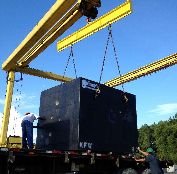
33 Lifting Devices

34 Lifting Best Practices Follow manufacturer recommendations. Do not move / lift or handle product until specified handling strength is achieved. Store in a manner that minimizes stress on structure. Specifications should address the development of a rigging/hoisting plan for products. Use a 4:1 Factor of Safety on inserts per OSHA Standards

35 Lifting Devices / Rigging How should a lifting device be specified? If structure is project specific allow manufacturer to select. If structure is a standard for repeat use, engineer or utility may select.


36 Pulling Irons Consider specifying pulling irons for electric/communication UUS Location Type Size Capacity Material


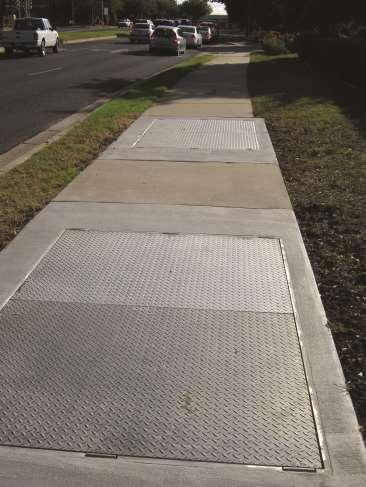
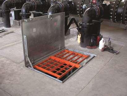
37 Entering and Exiting Utility Structures
38 Entering and Exiting (cont.) Access Hatches and Castings Labels and Lettering Lift Assist Gasketed Locking Accepts Vehicular and Airport Loadings Ladders Steps Safety Grate
39 Design

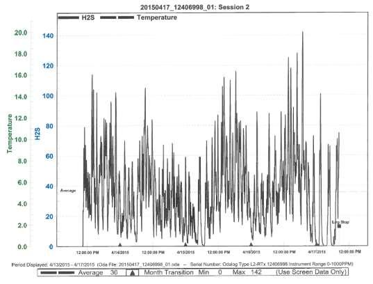
40 Design Environmental Factors (Corrosion) Video Inspection PS #3 Town of Livingston
41


42 10 Dia.- 22 deep Installed in 2007 Coal tar epoxy in & out 2 High FMs w/ 10 + drops Ductile Iron nonepoxy coated eaten through on one side Loss of wall thickness Exposed reinforcing steel
43

44 Hatch: 7.0 Lift Station walls: Ductile Iron Pipe Walls: 1.0


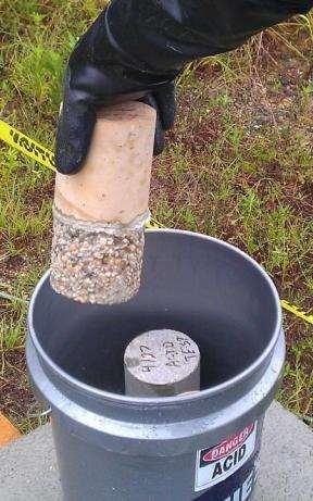
45 Design -Why High Strength Concrete? Durability 3 Days

46 High Performance Concrete Acid Trials

47 Design -Why High Strength Concrete? Increased Corrosion Resistance 4 Months
 -So why has there been variable")
 Must be Continuous")
48 Design - Coatings in Wastewater Chemical Resistance not that tough (ph of 3) -So why has there been variable success? Must be Adhered (proper surface prep) Must be Continuous (combat outgassing) At design thickness Must deal with joints


49 Calibrated for - Dielectric of Coating - Mil Thickness With variable voltage set - pass over substrate - makes a sound over problem spots - identified areas patched - test assures continuity and correct thickness

50 Design Admixtures in Concrete Conshield Anti-microbial Breaks the cycle in Phase II Interrupts the cell membrane of Thiobacillus Difficult to prove it is present, in correct dosage and activated Superplasticizers

51 Design Factors Compressive Strength 6500 PSI Reinforcement Wall Thickness 12
52 Design of Utility Structures Loads to Consider Surface surcharge Concentrated wheel loads Lateral loads Hydrostatic forces Point loads Live loads Dead loads Construction loads Pulling iron loads Other Factors to Consider Soil Bearing Capacity Connection Locations Penetrations Lifting and Handling Stresses
53 Design of Utility Structures (Cont.) Typical Design Loads per ASTM C857 A16 (AASHTO HS20) 16,000lbf/wheel Heavy Traffic A12 (AASHTO HS15) 12,000lbf/wheel Medium Traffic A8 (AASHTO H10) 8,000lbf/wheel Light Traffic A PSF Walkways (H20 Load) (A16 Load) Grade 2-0

54 Design of Utility Structures (Cont.)
 Precast Concrete Utility Structures")

55 Design (Cont.) Precast Concrete Utility Structures and the associated castings and hatches can even be designed for airport, railroad and port loadings.
56 Design of Utility Structures (Cont.) Concrete Thickness Sufficient to meet minimum reinforcement cover and withstand design loading conditions. Reinforcement Reinforcement design by structural calculations as required by code or as proven by testing.

57 Reinforcement Larger Diameter Reinforcement Shear Reinforcement - Stirrups Accurate Placement

58 Structural Calculations If Needed
59 Quality Assurance

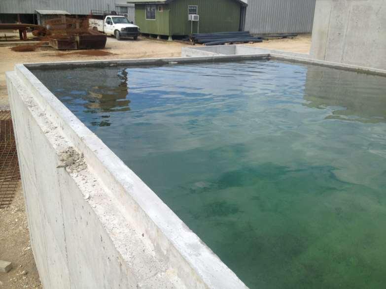
60 Quality Assurance- Water Testing

61 Quality Assurance- Dry Stacking
62 Shipping

63 Precast VS. Cast In Place What are the Limitations of Heavy Precast vs. Cast In Place? Ship under 18 wide.


64 Just-In-Time Delivery On Time No Weather Delays Precast risers ready and waiting to ship Completion Date Assurance!

65 Shipping Things to Consider Transportation Restrictions Height Width Weight Permitting Requirements What design criteria controls product size? Where is the center of gravity of the piece? Is specialized equipment and/or rigging required to load or install?
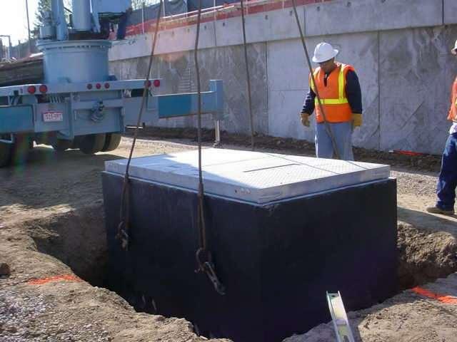
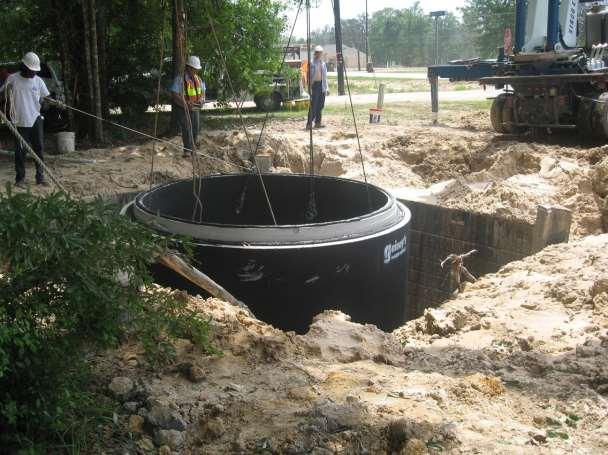
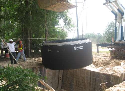
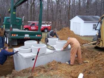
66 Installation
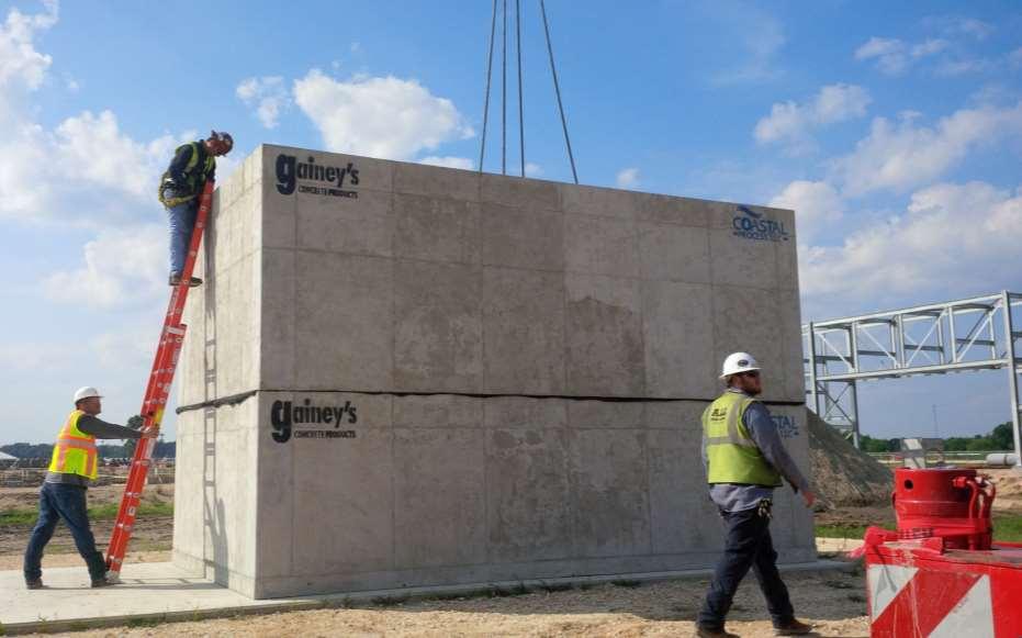
67 Rapid Installation

68 Installation Safety Requirements Site Conditions Excavation Bedding Placement Joints Joint Sealants Backfilling
 Safety factor of at least 5 is recommended on all lifting apparatus (chains, sling, spreader beams) OSHA regulation 29 CFR, Part 1926.")
69 Safety Considerations Verify that lifting apparatus such as slings, lift bars, chains, and hooks have adequate capacity and proper safety factors (at least 5) Safety factor of at least 4 is required on all devices (inserts) Safety factor of at least 5 is recommended on all lifting apparatus (chains, sling, spreader beams) OSHA regulation 29 CFR, Part on excavation work should be followed at all times.

70 Site Conditions Survey of the site Site must be accessible to the equipment necessary for offloading and installation. Verify overhead and below grade obstacles are not a concern.

71 Excavation Prior to excavation, all buried utilities should be identified and located. Excavations should be made with approximately 18 inches of clearance to allow for adequate compaction of backfill material Excavation slopes to comply with all applicable construction safety requirements.

72 Bedding Engineered bedding material should be used as necessary to provide a uniform bearing surface. A minimum 4 inch thick sand or granular bed overlaying a firm and uniform base is recommended unless otherwise specified.
73 Placement Improper installation can lead to damage of the structure, reduced structure life and safety hazards. Reference ASTM C891 Standard Practice for Installation of Underground Precast Concrete Utility Structures Reference NPCA Best Practices Manual for Precast Concrete Utility Vaults

74 Placement (Cont.) Prior to placement the structure s orientation should be confirmed. Inlet penetrations aligned in the proper directions. After placement, ensure the structure is level.

75 Joints For the manufacture of utility vaults, it is recommended that only interlocking joints be used. Typical joints include lap joints or tongue and groove joints. In cases of frost heave, differential settlement and ground water exposure, mechanical fasteners or secondary pours may be necessary
76 Joint Sealants High quality, flexible joint sealants and/or wraps can be used to achieve a dependable seal. Some characteristics: Workability over a wide range of temperatures Adhesion to clean, dry surfaces Good Performance over time (no shrinkage) Sealants should conform to ASTM C990 and be applied per manufacturers recommendations.


77 Installation Proper Installation Proper application of joint sealants Joint Sealant
78 Installation Different applications depending on nature of tank

79 Installation Joint Installation Guidelines
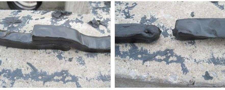
80 Installation Recommended Practice
81 Backfilling Place backfill in uniform, mechanically compacted layers. Layers should be less than 24 thick. Backfill material should be free of large stones (greater than 3 in diameter) and other debris.

82 Wrap-Up Questions??? Specifying Design Shipping Handling Installation

83 QUESTIONS PRECAST CONCRETE UTILITY STRUCTURES


84 To Sum It Up Our Precast will make YOU Look Good!
University of Delaware
 University Contact: Energy & Engineering Group (302) 831-1744 SECTION 03 45 00_PRECAST CONCRETE STRUCTURES PART 1 - GENERAL 1.01 RELATED DOCUMENTS A. Drawings and general provisions of the contract, including
SECTION XXXX POLYMER CONCRETE PUMP STATIONS
 SECTION XXXX POLYMER CONCRETE PUMP STATIONS PART 1 GENERAL 1.1 SUMMARY A. This specification shall govern for the furnishing of all work necessary for installation of polymer concrete pump stations to
SECTION PRECAST CONCRETE BIOSOLIDS STORAGE TANK
 PART 1 GENERAL 1.1 Summary SECTION 13200 PRECAST CONCRETE BIOSOLIDS STORAGE TANK A. Biosolids Storage Tank 1.2 System Description A. Precast concrete storage tank with precast concrete roof, beams, columns,
PRECAST CONCRETE ON-SITE WASTEWATER TANKS
 PRECAST CONCRETE ON-SITE WASTEWATER TANKS OUTLINE Purpose Precast Advantage Design Goals Applicable Standards Structural Design Materials Production Watertightness Installation NPCA Plant Certification
Changes for the. TOHOPEKALIGA WATER AUTHORITY Standards, Specifications and Details
 Changes for the 2017 TOHOPEKALIGA WATER AUTHORITY Standards, Specifications and Details The following changes are made to the existing standards and details to clarify or improve existing information.
SECTION UTILITY MANHOLES AND STRUCTURES
 SECTION 33 05 14 UTILITY MANHOLES AND STRUCTURES PART 1 GENERAL 1.1 SUMMARY A. Section Includes: 1. Precast reinforced concrete manholes and structures with tongue-and-groove joints with masonry transition
PASSAIC COUNTY TECHNICAL INSTITUTE CCA 1422 NEW S.T.E.M. BUILDING 2017
 SECTION 02630 - STORM DRAINAGE PART 1 - GENERAL 1.1 RELATED DOCUMENTS A. Drawings and general provisions of the Contract, including General and Supplementary Conditions and Division 01 Specification Sections,
UNIVERSITY OF MISSOURI Electrical Manholes and Handholes 2016 Q1
 GENERAL: The scope of this document is to provide instruction for the design and installation of medium voltage concrete electric manholes and handholes. DESIGN GUIDELINES: 1. Design for Manhole 1.1. The
PERMANENT PAVEMENT REPAIR NO SCALE
 SAWCUT EXISTING PAVEMENT 2" BITUMINOUS CONCRETE SURFACE COURSE, CLASS 2 (MIN) CLEAN EDGE PRIOR TO PAVING AND PAINT WITH LIQUID BITUMEN. INSTALL SEALANT OVER JOINT UPON COMPLETION 2" BITUMINOUS CONCRETE
MANHOLES, VAULTS AND CATCH BASINS SECTION A. Section Soil and Aggregate Materials. C. Section Storm Drainage Systems
 SECTION 02607-1 1.0 GENERAL 1.1 SCOPE: A. This section covers the work necessary for the construction of sanitary and storm system manholes, catch basins, and miscellaneous concrete structures complete.
SECTION 39 - MANHOLES TABLE OF CONTENTS
 Section SECTION 39 - MANHOLES TABLE OF CONTENTS Page 39-1 GENERAL... 39.1 39-2 CONCRETE MANHOLES... 39.1 39-2.01 NOT USED... 39.1 39-2.02 Concrete Storm Drain Manholes... 39.1 39-3 SADDLE SEWER MANHOLES...
VALLECITOS WATER DISTRICT SECTION PRECAST REINFORCED CONCRETE MANHOLES
 PART 1 GENERAL 1.1 DESCRIPTION A. This section includes materials, testing, and installation of precast concrete manholes, manhole bases, manhole frames, and covers. 1.2 RELATED WORK SPECIFIED ELSEWHERE
SECTION STORM SEWER COLLECTION SYSTEM
 SECTION 02722 STORM SEWER COLLECTION SYSTEM PART 1 GENERAL 1.01 SUMMARY A. This section addresses the installation of storm sewer collection mains and includes the acceptable products, materials, and construction
SECTION FACILITY SANITARY SEWERS
 SECTION 22 13 13 FACILITY SANITARY SEWERS PART 1 - GENERAL 1.1 RELATED DOCUMENTS A. Drawings and general provisions of the Contract, including General and Supplementary Conditions and Division 01 Specification
SECTION SANITARY SEWERAGE PART 1 GENERAL 1.01 RELATED DOCUMENTS
 SECTION 02530 - SANITARY SEWERAGE PART 1 GENERAL 1.01 RELATED DOCUMENTS A. Drawings and general provisions of the Contract, including General and Supplementary Conditions and Division 1 Specification Sections,
SECTION TRENCHING
 SECTION 31 23 17 TRENCHING PART 1 GENERAL 1.1 SUMMARY A. Section Includes: 1. Excavating trenches for utilities and utility structures. 2. Bedding. 3. Backfilling and compacting to subgrade elevations.
Delivering Reliability. Electrical Vaults. Power & Energy-Underground Structures
 A Delivering Reliability Electrical Vaults Power & Energy-Underground Structures A The Benefits of Precast Vaults Electrical vaults house power cables and transformers, and are a preferred alternative
16. Design of Pipeline Structures.
 16. Design of Pipeline Structures. a. General. 1) The following guidelines are for the design of structures for water and sewer pipelines including structural concrete and miscellaneous metals design.
CONSTRUCTION SPECIFICATION FOR THE INSTALLATION OF ELECTRICAL CHAMBER
 ONTARIO PROVINCIAL STANDARD SPECIFICATION METRIC OPSS 602 MARCH 1993 CONSTRUCTION SPECIFICATION FOR THE INSTALLATION OF ELECTRICAL CHAMBER 602.01 SCOPE 602.02 REFERENCES 602.05 MATERIALS TABLE OF CONTENTS
SECTION STORM DRAINAGE
 SECTION 02720 STORM DRAINAGE PART 1 - GENERAL 1.01 WORK INCLUDED A. Trenching and other excavation. B. Ground water control. C. Pipe bedding. D. Installation of storm drains and appurtenances. E. Installation
A. Gravity-Flow, Nonpressure, Drainage-Piping Pressure Rating: 10-foot head of water (30 kpa).
.") SECTION 221313 - FACILITY SANITARY SEWERS PART 1 - GENERAL 1.1 RELATED DOCUMENTS A. Drawings and general provisions of the Contract, including General and Supplementary Conditions and Division 01 Specification
SECTION 221313 - FACILITY SANITARY SEWERS PART 1 - GENERAL 1.1 RELATED DOCUMENTS A. Drawings and general provisions of the Contract, including General and Supplementary Conditions and Division 01 Specification
STORMCAPTURE. Installation Manual
 STORMCAPTURE Installation Manual Introduction Site Preparation Delivery & Installation LinkSlabs Backfill Introduction StormCapture (shown in Figure 1) is a total stormwater management system. The highly-configurable
Wastewater Capital Projects Management Standard Construction Specification
 CITY AND COUNTY OF DENVER ENGINEERING DIVISION Wastewater Capital Projects Management Standard Construction Specification 10.1 PRECAST CONCRETE PIPE 10.1.1 General This section covers material requirements,
SECTION 1 TERMS, DEFINITIONS, ABBREVIATIONS, UNITS OF MEASURE, AND SYMBOLS 1-3 ABBREVIATIONS Common Usage.
 SECTION 1 TERMS, DEFINITIONS, ABBREVIATIONS, UNITS OF MEASURE, AND SYMBOLS 1-3 ABBREVIATIONS. 1-3.2 Common Usage. Abbreviations Word or Words PAV.Pressure Aging Vessel PCC..Portland Cement Concrete PE.Polyethylene
SECTION PRECAST CONCRETE COVER SYSTEM
 SECTION 13500 PRECAST CONCRETE COVER SYSTEM PART 1 GENERAL 1.1 SYSTEM DESCRIPTION A. Design Criteria: 1. Precast manufacturer shall be responsible for structural design of individual precast components,
UPRR INDUSTRIAL LEAD BRIDGE T-WALL RETAINING WALL SYSTEM 5.0 x 7.5 UNITS DESIGN UNIT 018 WORK PACKAGE 04
 UPRR INDUSTRIAL LEAD BRIDGE T-WALL RETAINING WALL SYSTEM 5.0 x 7.5 UNITS DESIGN UNIT 018 WORK PACKAGE 04 1. Description This work shall consist of the design, manufacture and construction of a T-WALL structure
SECTION UTILITY POLYETHYLENE CONTAINMENT PIPE SYSTEMS
 SECTION 02670 UTILITY POLYETHYLENE CONTAINMENT PIPE SYSTEMS PART 1 - GENERAL 1.01 WORK INCLUDED A. Trenching and other excavation. B. Ground water control. C. Pipe bedding. D. Installation of containment
B. Fiberglass for construction in back lot easements placed on cast-in-place base.
 Section 02083 PART 1 G E N E R A L 1.01 SECTION INCLUDES A. Fiberglass manholes for unpaved areas placed on top of a precast base to form a manhole. B. Fiberglass for construction in back lot easements
Special Specification 6186 Intelligent Transportation System (ITS) Ground Box
 Ground Box") Special Specification Intelligent Transportation System (ITS) Ground Box 1. DESCRIPTION 2. MATERIALS Construct, furnish, install or remove Intelligent Transportation System (ITS) ground boxes for fiber
Special Specification Intelligent Transportation System (ITS) Ground Box 1. DESCRIPTION 2. MATERIALS Construct, furnish, install or remove Intelligent Transportation System (ITS) ground boxes for fiber
SECTION UNDERGROUND ELECTRICAL CONSTRUCTION
 PART 1 - GENERAL 1.1 DESCRIPTION SECTION 26 05 41 UNDERGROUND ELECTRICAL CONSTRUCTION A. This section specifies the furnishing, installation, and connection of precast manholes and pullboxes with ducts
SECTION MECHANICALLY STABILIZED EARTH RETAINING WALLS
 SECTION 13100 MECHANICALLY STABILIZED EARTH RETAINING WALLS PART 1 -- GENERAL 1.01 THE REQUIREMENT A. Includes all labor, material, equipment, testing and submittals required to design and complete construction
Table of Contents. Section Structures for Sanitary and Storm Sewers Section Includes Description of Work 1. 1.
 SUDAS Standard Specifications Division 6 - Structures for Sanitary and Storm Sewers Table of Contents Section 6010 - Structures for Sanitary and Storm Sewers Page No. Part 1 - General 1.01 Section Includes
CONSULTANT PROCEDURES & DESIGN GUIDELINES Electrical Manholes and Handholes UNIVERSITY OF MISSOURI
 GENERAL: The scope of this document is to provide instruction for the installation of concrete electric manholes. DESIGN GUIDELINES: 1. Materials for Manhole 1.1. Cast-in-Place or Pre-Cast concrete may
SECTION DOWNSTREAM DEFENDER
 SECTION 02631 DOWNSTREAM DEFENDER PART 1 - GENERAL 1.01 SCOPE A. Work described in this section includes furnishing all labor, equipment, materials, tools and incidentals required for a complete and operable
TCC/SHORE TRANSIT BUS MAINTENANCE FACILITY PHASE II
 SECTION 334100 - STORM UTILITY DRAINAGE PIPING PART 1 - GENERAL 1.1 RELATED DOCUMENTS A. Drawings and general provisions of the Contract, including General and Supplementary Conditions and Division 01
Flygt Advanced Low Pressure Sewer System Package
 PURPOSE Xylem The purpose of this document is to provide a brief reference to the recommended methods and procedures for installing Flygt's underground sump and sewage basins to ensure that damage or premature
1. C-478 Specification for Precast Reinforced Manhole Sections. 2. D-3034 Specification for Polyvinyl Chloride (PVC) Pipe.
 Pipe.") SECTION 33 30 00 - SANITARY SEWER PART 1 - GENERAL 1.1 SCOPE OF WORK A. This Section specifies the requirements for furnishing and placing sanitary sewer pipe, laterals, stubs, and appurtenances. The pipe
SECTION 33 30 00 - SANITARY SEWER PART 1 - GENERAL 1.1 SCOPE OF WORK A. This Section specifies the requirements for furnishing and placing sanitary sewer pipe, laterals, stubs, and appurtenances. The pipe
A.2.a Random Riprap... Table
 3601 RIPRAP MATERIAL 3601.1 SCOPE Provide stone and filter layer material for use in random or hand-placed riprap, gabion, and revet mattress construction. 3601.2 REQUIREMENTS A Stones A.1 Quality Provide
Hydraulic Updates. History of 603/604
 Ohio Department of Transportation John R. Kasich, Governor Jerry Wray, Director Hydraulic Updates SS 802 Constructing and Inspecting Pipe Culverts, Sewers, Drains and Drainage Structures AND SS 902 Conduit
UNIFIED FACILITIES GUIDE SPECIFICATIONS
 USACE / NAVFAC / AFCEC / NASA UFGS-33 16 13.16 (April 2006) ----------------------------- Preparing Activity: NAVFAC Replacing without change UFGS-13208 (August 2004) UNIFIED FACILITIES GUIDE SPECIFICATIONS
Fabrication and Installation Table of Contents
 Fabrication and Installation Table of Contents HDPE AQUASHIELD PRODUCTS 2 Fabrication and Installation 2 System Fabrication 3 Aqua-Swirl Installation 4 Step 1 Excavation and Bedding 4 Step 2 Pipe Connection
3/23/2016. Happy Pi Day! What We Will Discuss. Best Practices for Precast Concrete Tank Inspections
 Best Practices for Precast Concrete Tank Inspections 29 th Annual GSDI Spring Septic System Conference & Expo Monday March 14, 2016 Claude Goguen, PE, LEED AP, National Precast Concrete Association Happy
SECTION PRECAST CONCRETE MANHOLES
 SECTION 03 48 10 PRECAST CONCRETE MANHOLES PART 1: GENERAL 1.01 SECTION INCLUDES A. Precast concrete manholes for sanitary sewers and water lines or as indicated on the Drawings. B. Precast concrete sanitary
MagnumStone Specifications Gravity
 MagnumStone Specifications Gravity SPECIFICATION FOR MAGNUMSTONE GRAVITY MECHANICALLY STABILIZED EARTH SYSTEM PART 1: GENERAL.01Description The work consists of supplying and installing all aspects of
Installation Manual. ArchCast Bridge. 3-Sided Precast Concrete Bridge Structure
 ArchCast Bridge 3-Sided Precast Concrete Bridge Structure Installation Manual Salem Location: 749 West Commercial Ave. Salem, IL 62881 (618) 548-1190 countymaterials.com Email: info@countymaterials.com
SECTION 39 - MANHOLES TABLE OF CONTENTS 39-1 GENERAL PRECAST CONCRETE MANHOLES
 Section SECTION 39 - MANHOLES TABLE OF CONTENTS 39-1 GENERAL... 39-1 39-2 PRECAST CONCRETE MANHOLES... 39-1 39-2.01 Precast Concrete Storm Drain Manholes... 39-1 39-3 SADDLE MANHOLES... 39-2 39-3.01 Saddle
Qualified Product Policy 15 Drainage Structure Miscellaneous Components Qualified Product List 14 [G] Heavy Duty Gray Cast Iron
![Qualified Product Policy 15 Drainage Structure Miscellaneous Components Qualified Product List 14 [G] Heavy Duty Gray Cast Iron](/thumbs/80/80930557.jpg "Qualified Product Policy 15 Drainage Structure Miscellaneous Components Qualified Product List 14 [G] Heavy Duty Gray Cast Iron") SCDOT Qualified Product Policy 15 1 SOUTH CAROLINA DEPARTMENT OF TRANSPORTATION Drainage Structure Miscellaneous Components (See also QPL14 for precast drainage structure components) This policy covers
SCDOT Qualified Product Policy 15 1 SOUTH CAROLINA DEPARTMENT OF TRANSPORTATION Drainage Structure Miscellaneous Components (See also QPL14 for precast drainage structure components) This policy covers
Section 7: Specifications
 Section 7: Specifications 29 31 Building Boundary of Clear Area See Note # 1 8' Shrubs 8' Concrete Pad Equipment 8' TRAVELED WAY M Meter Pedestal 8' Curb Protective Vehicle Posts (Bollards) If Required
Section 403. DRAINAGE STRUCTURES
 403.01 Section 403. DRAINAGE STRUCTURES 403.01. Description. This work consists of adjusting, constructing, or temporarily lowering drainage structures and cleaning existing drainage structures and leads
Construction Red Flags. April 17, 2018 William (Clay) Herndon, P.E.
 Herndon, P.E.") Construction Red Flags April 17, 2018 William (Clay) Herndon, P.E. 1 General Site Management & Safety Site Safety Site Specific PPE Hard Hat, Safety Glass, Vest What does the Contractor provide? Safe working
Construction Red Flags April 17, 2018 William (Clay) Herndon, P.E. 1 General Site Management & Safety Site Safety Site Specific PPE Hard Hat, Safety Glass, Vest What does the Contractor provide? Safe working
SECTION RIGID PAVEMENT. 1. Portland Cement Concrete (PCC) pavement. 2. Section Aggregate Base Course.
 pavement. 2. Section Aggregate Base Course.") SECTION 02750 RIGID PAVEMENT PART 1 GENERAL 1.1 SUMMARY A. Section Includes: 1. Portland Cement Concrete (PCC) pavement. B. Related Sections: 1.2 REFERENCES 1. Section 02315 Excavation. 2. Section 02721
SECTION 02750 RIGID PAVEMENT PART 1 GENERAL 1.1 SUMMARY A. Section Includes: 1. Portland Cement Concrete (PCC) pavement. B. Related Sections: 1.2 REFERENCES 1. Section 02315 Excavation. 2. Section 02721
Michigan State University Construction Standards ELECTRICAL UNDERGROUND DUCTS AND MANHOLES PAGE
 PAGE 337119-1 SECTION 337119 PART 1 - GENERAL 1.1 RELATED DOCUMENTS A. Drawings and general provisions of the Contract, including General and Supplementary Conditions and Division 01 Specification Sections,
SPECIAL SPECIFICATION 5925 Polyvinyl Cloride (PVC) Sewer Pipe and Fittings
 Sewer Pipe and Fittings") 1993 Specifications CSJ 0144-01-060 SPECIAL SPECIFICATION 5925 Polyvinyl Cloride (PVC) Sewer Pipe and Fittings 1. General. (1) Scope. This Section includes the furnishing, installation, and subsequent
1993 Specifications CSJ 0144-01-060 SPECIAL SPECIFICATION 5925 Polyvinyl Cloride (PVC) Sewer Pipe and Fittings 1. General. (1) Scope. This Section includes the furnishing, installation, and subsequent
SPECIAL SPECIFICATION 6664 Level (3) Communications System
 Communications System") 2004 Specifications CSJ 1200-05-014 SPECIAL SPECIFICATION 6664 Level (3) Communications System 1. Description. A. This Item will govern the installation of all facilities belonging to Level (3) Communications,
2004 Specifications CSJ 1200-05-014 SPECIAL SPECIFICATION 6664 Level (3) Communications System 1. Description. A. This Item will govern the installation of all facilities belonging to Level (3) Communications,
SPECIAL SPECIFICATION 6658 Time Warner Communications System
 2004 Specifications CSJ 1200-05-014 1. Description. SPECIAL SPECIFICATION 6658 Time Warner Communications System A. This Item will govern the installation of all facilities belonging to Time Warner Cable
SPECIFICATIONS FOR PRECAST MODULAR BLOCK RETAINING WALL SYSTEM (revised 5/8/7)
") Page 1 of 7 STONE STRONG SYSTEMS SPECIFICATIONS FOR PRECAST MODULAR BLOCK RETAINING WALL SYSTEM (revised 5/8/7) PART 1: GENERAL 1.01 Description A. Work includes furnishing and installing precast modular
Page 1 of 7 STONE STRONG SYSTEMS SPECIFICATIONS FOR PRECAST MODULAR BLOCK RETAINING WALL SYSTEM (revised 5/8/7) PART 1: GENERAL 1.01 Description A. Work includes furnishing and installing precast modular
San Antonio Water System Standard Specifications for Construction ITEM NO. 848 SANITARY SEWERS
 ITEM NO. 848 SANITARY SEWERS 848.1 DESCRIPTION: This item shall govern the furnishing, installation and jointing of sanitary sewer pipe of the size and type specified by the project's plans and specifications.
207 TEMPORARY SEDIMENT AND EROSION CONTROLS
 2013 Construction and Material Specifications Hydraulics and Environmental Summary Ron Trivisonno, Office of Construction Administration 207 TEMPORARY SEDIMENT AND EROSION CONTROLS This item has been removed
Construction Inspection Checklists
 III. Construction Inspection Checklists 33 Bioretention - Construction Inspection Checklist Project: Location: Site Status: Date: Time: Inspector: Construction Sequence Satisfactory / Unsatisfactory Comments
STANDARD SPECIFICATION FOR CRIBLOCK CONCRETE CRIBWALL
 STANDARD SPECIFICATION FOR CRIBLOCK CONCRETE CRIBWALL 1. SCOPE 2. DESIGN 3. MATERIALS 4. CONSTRUCTION 5. METHOD OF MEASUREMENT AND PAYMENT SCOPE This Specification sets out requirements for the design,
SECTION PRECAST CONCRETE MANHOLES
 SECTION 02601 PRECAST CONCRETE MANHOLES PART 1 GENERAL 1.1 The work specified in this section shall include the furnishing, hauling, and placing of all precast manholes shown on the drawings and as specified
INSTALLATION MANUAL. B-710/760 H20 SERIES MODULAR UST to AST TRANSITION SUMP
 INSTALLATION MANUAL B-710/760 H20 SERIES MODULAR UST to AST TRANSITION SUMP H20-RATED B-710 WITH 2 RISERS, RACK SYSTEM AND BOLLARDS B-710 SPLIT LID TRANSITION SUMP SHOWN WITH H20-RATED DIAMOND PLATE LID
Drainage structure refers to manholes, catch basins, leaching basins, inlets and drop inlets. Drainage structures are designated as follows.
 403.01 Section 403. DRAINAGE STRUCTURES 403.01 Description. Adjust, construct, or temporarily lower drainage structures. Clean existing drainage structures and leads as directed by the Engineer. Drainage
SPECIFICATIONS FOR PRECAST MODULAR BLOCK RETAINING WALL SYSTEM (revised 9/17/18)
") Page 1 of 8 STONE STRONG SYSTEMS SPECIFICATIONS FOR PRECAST MODULAR BLOCK RETAINING WALL SYSTEM (revised ) PART 1: GENERAL 1.01 Description A. Work includes furnishing and installing precast modular blocks
Page 1 of 8 STONE STRONG SYSTEMS SPECIFICATIONS FOR PRECAST MODULAR BLOCK RETAINING WALL SYSTEM (revised ) PART 1: GENERAL 1.01 Description A. Work includes furnishing and installing precast modular blocks
ITEM D-701 PIPE FOR STORM DRAINS AND CULVERTS
 ITEM D-701 PIPE FOR STORM DRAINS AND CULVERTS 701-1 DESCRIPTION 701-1.1 This item shall consist of the construction of pipe culverts, and storm drains, removal of existing storm pipes, connections to existing
AMENDMENTS TO OPSS 408 (OCT 89) CONSTRUCTION SPECIFICATION FOR ADJUSTING OR REBUILDING MANHOLES, CATCH BASINS, DITCH INLETS AND VALVE CHAMBERS
 CONSTRUCTION SPECIFICATION FOR ADJUSTING OR REBUILDING MANHOLES, CATCH BASINS, DITCH INLETS AND VALVE CHAMBERS") Works and Emergency Services CITY OF TORONTO WATER AND WASTEWATER SERVICES STANDARD CONSTRUCTION SPECIFICATIONS TS 408 November 2010 AMENDMENTS TO OPSS 408 (OCT 89) CONSTRUCTION SPECIFICATION FOR ADJUSTING
Works and Emergency Services CITY OF TORONTO WATER AND WASTEWATER SERVICES STANDARD CONSTRUCTION SPECIFICATIONS TS 408 November 2010 AMENDMENTS TO OPSS 408 (OCT 89) CONSTRUCTION SPECIFICATION FOR ADJUSTING
SPECIAL SPECIFICATION 3504 Septic Tank System
 1993 Specifications CSJ s 3136-01-126, etc. & 0683-01-070, etc. SPECIAL SPECIFICATION 3504 Septic Tank System 1. Description. This Item shall govern for all materials, equipment and labor necessary for
New Fulton State Hospital Energy Control Center and Services Building (ECC/SVC) Project Number: M
 Project Number: M") SECTION 334100 - STORM UTILITY DRAINAGE PIPING PART 1 -GENERAL 1.1 RELATED DOCUMENTS A. Drawings and general provisions of the Contract, including General and Supplementary Conditions and Division 01 Specification
SECTION 334100 - STORM UTILITY DRAINAGE PIPING PART 1 -GENERAL 1.1 RELATED DOCUMENTS A. Drawings and general provisions of the Contract, including General and Supplementary Conditions and Division 01 Specification
TECHNICAL SPECIFICATION FOR CURED-IN-PLACE MANHOLE REHABILITATION LINER SYSTEM
 TECHNICAL SPECIFICATION FOR CURED-IN-PLACE SYSTEM PART 1 GENERAL 1.01 SCOPE OF WORK Furnish all materials, labor, equipment, tools and required incidentals for providing and installing a resin impregnated
VERTI-BLOCK - DESIGN MANUAL
 Company Information General Information Verti-Block is the latest innovative forming system from Verti-Crete, LLC. Recognized worldwide for outstanding aesthetics and performance, Verti-Crete s proprietary
G. Shop drawing of wall with all dimensions, details, and finishes. Drawings must include post foundations.
 DURA-CRETE S-SERIES PRECAST CONCRETE WALL SPECIFICATIONS PART 1 GENERAL 1.01 SECTION INCLUDES A. Concrete Screen Wall Description: Work under this item shall consist of furnishing and erecting a wall in
Construction Specification for Utility Adjustments
 Engineering & Construction Services Division Standard Specifications for Road Works TS 4.50 September 2017 for Utility Adjustments Table of Contents TS 4.50.01 SCOPE... 2 TS 4.50.02 REFERENCES... 2 TS
SECTION MANHOLES AND STRUCTURES. A. Section Includes: 1. Manholes for water, storm drain and sanitary sewer systems.
 SECTION 33 05 13 MANHOLES AND STRUCTURES PART 1 GENERAL 1.1 SUMMARY A. Section Includes: 1. Manholes for water, storm drain and sanitary sewer systems. B. Related Sections: 1. Section 03 20 00 - Concrete
SECTION CONCRETE MANHOLES PART 1 - GENERAL 1.1 SUMMARY. A. Section Includes:
 SECTION 330561 - CONCRETE MANHOLES PART 1 - GENERAL 1.1 SUMMARY A. Section Includes: 1. Modular precast concrete manholes and structures with tongue-and-groove joints and [masonry] transition to cover
Employment Intensive Infrastructure Program (EIIP) in Lebanon ANNEX 2
 in Lebanon ANNEX 2") Employment Intensive Infrastructure Program (EIIP) in Lebanon ANNEX 2 PARTICULAR SPECIFICATIONS FOR THE CONSTRUCITON OF STORM WATER DRAINAGE NETWORK March 2018 BUREAU TECHNIQUE POUR LE DEVELOPPEMENT P.O.B
Employment Intensive Infrastructure Program (EIIP) in Lebanon ANNEX 2 PARTICULAR SPECIFICATIONS FOR THE CONSTRUCITON OF STORM WATER DRAINAGE NETWORK March 2018 BUREAU TECHNIQUE POUR LE DEVELOPPEMENT P.O.B
SECTION STRUCTURAL REINFORCED POLYMER COMPOSITE PEDESTRIAN BRIDGE DECK
 SECTION 06610 STRUCTURAL REINFORCED POLYMER COMPOSITE PEDESTRIAN BRIDGE DECK PART 1 GENERAL 1.1 SUMMARY A. A. This Section includes the requirements for furnishing and installing all Structural Reinforced
Fiberglass Basin Installation Reference Guide
 Fiberglass Basin Installation Reference Guide PURPOSE The purpose of this is to provide a brief reference to the recommended methods and procedures for installing Topp Industries underground sump and sewage
TILT-UP PRECAST CONCRETE SANDWICH PANELS. A. Work includes, but is not limited to, the following:
 PART 1 GENERAL 1.01 SUMMARY SECTION 03460 TILT-UP PRECAST CONCRETE SANDWICH PANELS A. Work includes, but is not limited to, the following: 1. Architectural precast concrete sandwich wall panels. 2. Integral
SECTION STORM DRAIN
 PART 1 - GENERAL 1-01 SECTION INCLUDED A. Furnishing and installing storm drainage facilities, including pipe, cleanout, manhole structures and inlet structures. 1-02 RELATED SECTIONS A. Division 00 Contract
ITEM 481 MONOLITHIC REINFORCED CONCRETE BOX SEWERS
 AFTER FEBRUARY 1, 2011 ITEM 481 MONOLITHIC REINFORCED CONCRETE BOX SEWERS 481.1 Description. This specification shall govern for the construction of monolithic, reinforced concrete box sewers of the size,
SECTION BASIC ELECTRICAL MATERIALS AND METHODS
 SECTION 26 05 05 BASIC ELECTRICAL MATERIALS PART 1 - GENERAL 1.1 SUMMARY A. Section includes the limited scope construction materials and methods for application with electrical installations as follows:
GUIDELINES FOR RETAINING WALLS 4-0 IN HEIGHT OR LESS
 GUIDELINES FOR RETAINING WALLS 4-0 IN HEIGHT OR LESS Version 2014-11-11 Prepared by: Building Development Division Department of Development Services 5 County Complex Ct. Suite 120 Prince William, VA 22192
Section 4 Service Lines
 Section 4 Service Lines A. General 1. A service line is that portion of a sanitary sewer line that extends from the outer building wall or foundation wall to its connection with the sewer lateral at the
THIS IS A COURTESY COPY OF THIS RULE. ALL OF THE DEPARTMENT S RULES ARE COMPILED IN TITLE 7 OF THE NEW JERSEY ADMINISTRATIVE CODE.
 (f) The minimum requirements for construction, materials and foundations of grease traps shall be the same as those required for septic tanks, as prescribed in N.J.A.C. 7:9A-8.2. (g) The inlet and outlet
Table of Contents. Section Structures for Sanitary and Storm Sewers Section Includes Description of Work 1. 1.
 SUDAS Standard Specifications Division 6 - Structures for Sanitary and Storm Sewers Table of Contents Section 6010 - Structures for Sanitary and Storm Sewers Page No. Part 1 - General 1.01 Section Includes
CONSTRUCTION SPECIFICATION FOR INSTALLATION OF ELECTRICAL CHAMBERS
 ONTARIO PROVINCIAL STANDARD SPECIFICATION OPSS.PROV 602 NOVEMBER 2017 CONSTRUCTION SPECIFICATION FOR INSTALLATION OF ELECTRICAL CHAMBERS TABLE OF CONTENTS 602.01 SCOPE 602.02 REFERENCES 602.03 DEFINITIONS
San Antonio Water System Standard Specifications for Construction ITEM NO. 853 SANITARY SEWER GLASS-FIBER REINFORCED POLYESTER (FRP) MANHOLES
 MANHOLES") ITEM NO. 853 SANITARY SEWER GLASS-FIBER REINFORCED POLYESTER (FRP) MANHOLES 853.1 DESCRIPTION: This item shall govern the construction of FRP sanitary sewer complete in place and the material therein,
ITEM NO. 853 SANITARY SEWER GLASS-FIBER REINFORCED POLYESTER (FRP) MANHOLES 853.1 DESCRIPTION: This item shall govern the construction of FRP sanitary sewer complete in place and the material therein,
SANITARY SEWERS. B. Construct or relocate building sanitary sewer services, stubs, and connections.
 SANITARY SEWERS PART 1 - GENERAL 1.01 SECTION INCLUDES A. Sanitary Sewer Gravity Mains B. Sanitary Sewer Force Mains C. Sanitary Sewer Services 1.02 DESCRIPTION OF WORK A. Construct sanitary sewer gravity
Table of Contents. Section Structures for Sanitary and Storm Sewers Section Includes Description of Work 1. 1.
 SUDAS Standard Specifications Division 6 - Structures for Sanitary and Storm Sewers Table of Contents Section 600 - Structures for Sanitary and Storm Sewers Page No. Part - General.0 Section Includes.0
SECTION 803 SEWER MANHOLES
 SECTION 803 SEWER MANHOLES 803-1 DESCRIPTION: This Work consists of removal and disposal of existing manholes, if necessary, and furnishing and constructing new precast concrete sanitary sewer manholes,
A. This Section includes sanitary waste and vent piping inside the building and to locations indicated.
 SECTION 221316 SANITARY WASTE AND VENT PIPING PART 1 - GENERAL 1.1 RELATED DOCUMENTS A. Drawings and general provisions of the Contract, including General and Supplementary Conditions and Division 01 Specification
TABLE OF CONTENTS
 DIVISION 33: SEWER AND SEPTIC SYSTEMS 33 3633 UTILITY SEPTIC TANK DRAINAGE FIELD TABLE OF CONTENTS 33 0000-1 SECTION 33 3633-- UTILITY SEPTIC TANK DRAINAGE FIELD PART 1 - GENERAL 1.1 SUMMARY A. Includes
Miscellaneous and Cast Iron Listings
 aeconcrete.com May 2017 Miscellaneous and Cast Iron Listings Drawing Number Item Description Product Size (Length X Width X Depth in mm) SVVZ-20-SUMP-C Drainage Sump w/ Cover 660 x 510 x 765 i.d. SVVZ-NC-SUMP-C
STANDARD SPECIFICATION FOR OIL GRIT SEPARATOR (OGS) STORMWATER QUALITY TREAMENT DEVICE
 STORMWATER QUALITY TREAMENT DEVICE") STANDARD SPECIFICATION FOR OIL GRIT SEPARATOR (OGS) STORMWATER QUALITY TREAMENT DEVICE PART 1 GENERAL 1.1 WORK INCLUDED This section specifies requirements for constructing underground stormwater treatment
STANDARD SPECIFICATION FOR OIL GRIT SEPARATOR (OGS) STORMWATER QUALITY TREAMENT DEVICE PART 1 GENERAL 1.1 WORK INCLUDED This section specifies requirements for constructing underground stormwater treatment
Prestressed Concrete Tanks. Design & Construction
 Prestressed Concrete Tanks Design & Construction The PRELOAD Advantage PRELOAD has maintained a focused vision on designing and constructing the highest-quality and most-durable liquid storage tanks for
ROTONDO ENVIRONMENTAL SOLUTIONS, LLC PERIMETER STYLE SANDFILTER * INSTALLATION PROCEDURES
 ROTONDO ENVIRONMENTAL SOLUTIONS, LLC PERIMETER STYLE SANDFILTER * INSTALLATION PROCEDURES *Patent Pending Rotondo Environmental Solutions, LLC 4950 C Eisenhower Ave, Alexandria, VA 22304 (703)212 4830
TYPICAL INSTALLATION INSTRUCTIONS
 TYPICAL INSTALLATION INSTRUCTIONS Environment One Grinder Pump Feature Identification 1. Grinder Pump Basin High density polyethylene (HDPE) 2. Accessway Cover Painted Steel 3. Electrical Quick Disconnect
SCALE BAR 1:2500 RM OF WOODLANDS OVERALL PLAN - LOW PRESSURE SEWER MAIN. Certificate of Authorization JESSICA MANNESS ENGINEERING, INC. No.
 OF SURVEY OVERALL PLAN - LOW PRESSURE SEWER MAIN 0 50 100 SCALE BAR 1:2500 200 500 THIS IS NOT A LEGAL PLAN - CONCEPT ONLY OF SURVEY PLAN - LOW PRESSURE SEWER MAIN 0 50 100 SCALE BAR 1:2500 200 500 THIS
SECTION 1 GENERAL NOTES
 ISSUE DATE NOVEMBER 1st, 2011 SECTION 1 Page List Page Number Page Title COVER COVER GN-01 PAGE 1 GN-02 PAGE 2 GN-03 PAGE 3 GN-04 PAGE 4 GN-05 PAGE 5 GN-06 PAGE 6 GN-07 PAGE 7 : 1. (CCU) STANDARD SPECIFICATIONS
SECTION TILT-UP PRECAST CONCRETE. A. Work includes, but is not limited to, the following:
 SECTION 03470 TILT-UP PRECAST CONCRETE PART 1 GENERAL 1.01 SUMMARY A. Work includes, but is not limited to, the following: 1. Precast wall panels. 2. Forms and casting beds. 3. Concrete. 4. Reinforcing