PART 5 WATER SYSTEMS
|
|
|
- Ronald Wade
- 6 years ago
- Views:
Transcription
1 PART 5 WATER SYSTEMS Abbreviations and Symbols Plan 501 Abbreviations and symbols for water Concrete Boxes and Hardware " Frame and cover " Frame and cover Concrete boxes Fire Hydrants 511 Fire hydrant with valve Meters 521 3/4" and 1" meter /2" and 2" meter " & 4" Compound meter with 2" bypass " Compound meter with 2" bypass " Compound meter with 2" bypass " Turbo meter with 6" turbo meter and 2" bypass Monitoring Systems 535 Electrolysis monitoring station details Piping 541 Water service line Waterline loop Fire hydrant relocation /4" and 1" Service taps /2" and 2" Service taps Trust Blocks 561 Direct bearing thrust block Tie-down thrust restraints Trenching See Trenching requirements under Section 3 Valves 571 2" Washout valve Detector check valve with 3/4" bypass meter " Pressure reducing valve with 2" bypass Cover collar for water valve boxes Air release assembly General 593 Pressurized irrigation water and potable water interface
2 Abbreviations and symbols for water 1. LETTERING SIZE: 100 Leroy minimum except for line type and other background information. Use 120 Leroy for new work installation. 2. LETTERING STYLE: Capital letters preferred. 3. EXISTING IMPROVEMENTS: Shown in light shaded dashed line. 4. NEW IMPROVEMENTS: Shown in solid continuous line. 204
3
4 27" Frame and cover 1. CASTINGS: Grey iron class 30 minimum per ASTM A COATINGS: Except machined surfaces, coat all metal parts with asphaltum paint. 3. INSCRIPTIONS: Cast the name of the agency or it's acronym as the first line. Cast the word `WATERWORKS' as the second line. Cast the word `VALVE' (or applicable word) as the third line. Cast all letters on the cover in upper case flush with the surface finish. 4. HEAT NUMBER: Place foundry and heat number on the inside of the frame and on the bottom of the cover. 5. FIT: designates machined surface. Give the frame and cover a machine finish so the cover will not rock. 6. MANHOLE STRUCTURE: See Plan No
5
6 38" Frame and double cover 1. CASTINGS: Grey iron class 35 minimum per ASTM A COATINGS: Except machined surfaces, coat all metal parts with asphaltum paint. 3. INSCRIPTIONS: Cast the name of the agency or it's acronym as the first line. Cast the word `WATERWORKS' as the second line. Cast the word `VALVE' (or applicable word) as the third line. Cast all letters on the cover in upper case flush with the surface finish. 4. HEAT NUMBER: Place foundry and heat number on the inside of the frame and on the bottom of the cover. 5. FIT: designates machined surface. Give the frame and cover a machine finish so the cover will not rock. 6. MANHOLE STRUCTURE: See Plan No
7
8 Concrete boxes 1. INSPECTION: Prior to backfilling around concrete box, secure inspection of installation by ENGINEER. 2. BACKFILL: Provide and place per APWA Section Compact per APWA Section to a modified proctor density of 95 percent or greater. Maximum lift thickness is 8 inches before compaction. 3. REINFORCEMENT: ASTM A 615, grade 60, deformed steel. See APWA Section requirements. 4. CONCRETE: Class 4000 per APWA Section Place concrete per APWA Section Cure per APWA Section WALL PENETRATIONS: Fill annular space around piping with waterproof sealer. 6. COVER PLACEMENT: Place frame and cover directly over valve or meter location. 210
9
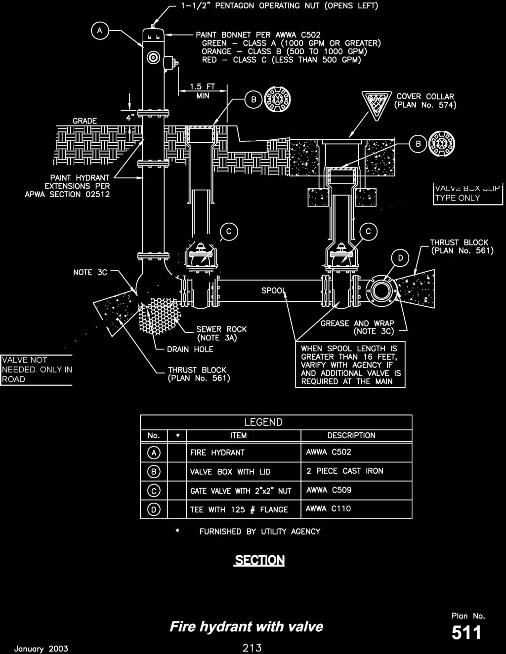
10 Fire hydrant with valve 1. INSPECTION: Prior to backfilling, secure inspection of installation by ENGINEER. 2. BACKFILL: Provide and place per APWA Section Compact per APWA Section to a modified proctor density of 95 percent or greater. Maximum lift thickness is 8 inches before compaction. 3. HYDRANT: Dry barrel per AWWA C502. Additional water system requirements are specified in APWA Section A. Provide at least 1 cubic yard of APWA Section sewer rock around drain hole at base of hydrant. Wrap plastic over sewer rock to prevent silting. B. Paint fire hydrant to agency's fire hydrant paint code. C. Apply non-oxide grease to all buried metal surfaces. Wrap with 8 mil thick polyethylene sheet and tape wrap. D. Notify fire department as soon as hydrant is placed in service. 4. THRUST BLOCKS: A. Prior to pouring concrete, wrap pipe system with 8 mil thick plastic sheet to prevent bonding of concrete to pipe system. B. Not required for flange or welded pipe systems. 212
11
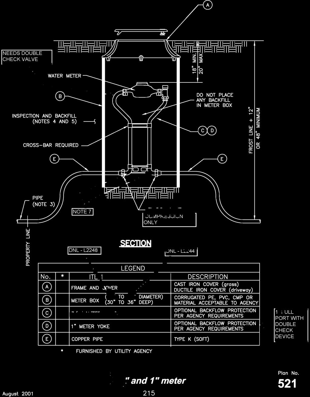
12 3/4" and 1" meter 1. METER PLACEMENT: A. In new construction, install meter at center of lot or per agency requirements. B. All meters are to be installed in the park strip or within 7 feet of the property line (street side). C. Do not install meters under driveway approaches, sidewalks, or curb and gutter. 2. METER BOX: A. In landscaped areas and driveway approaches, set box so grade of the frame and cover matches the grade of the surrounding surface. B. In street surfaces or other vehicular traffic areas, provide the same type of meter box as required for 1 1/2" and 2 service meters. See Plan PIPE: Coordinate with utility agency or property owner for type of pipe to be used outside of right-of-way. 4. INSPECTION: Prior to backfilling around meter box, secure inspection of installation by ENGINEER. 5. BACKFILL: Provide and place per APWA Section Compact per APWA Section to a modified proctor density of 95 percent or greater. Maximum lift thickness is 8 inches before compaction. 6. CASTING: Grey iron class 35 minimum per ASTM A
13
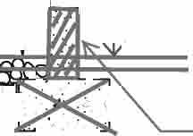
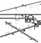
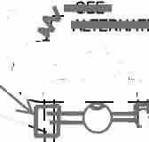
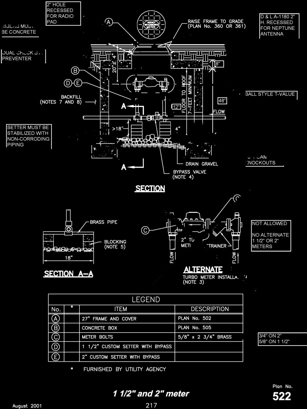
14 1 1/2" and 2" meter 1. METER PLACEMENT: A. In new construction, install meter at center of lot or per agency requirements. B. All meters are to be installed in the park strip or within 7 feet of the property line (street side). C. Do not install meters under driveway approaches, sidewalks, or curb and gutter. 2. PIPE: Install type `K' copper pipe to property line. Coordinate with utility agency for type of pipe to be used outside of right-of-way. 3. ALTERNATE: Turbine meters are required on all systems used exclusively for irrigation or fire protection. Where domestic use is applicable, use a standard meter. 4. BYPASS VALVE: Lock in off position. 5. BLOCKING: Use clay brick or concrete block. 6. CONCRETE BOX: A. Center frame and cover over water meter. B. Allow 1 inch clearance around waterline where line passes through wall. Seal opening with compressible seal. 7. INSPECTION: Prior to backfilling around the meter box, secure inspection of installation by ENGINEER. 8. BACKFILL: Provide and place per APWA Section Compact per APWA Section to a modified proctor density of 95 percent or greater. Maximum lift thickness is 8 inches before compaction. 216
15
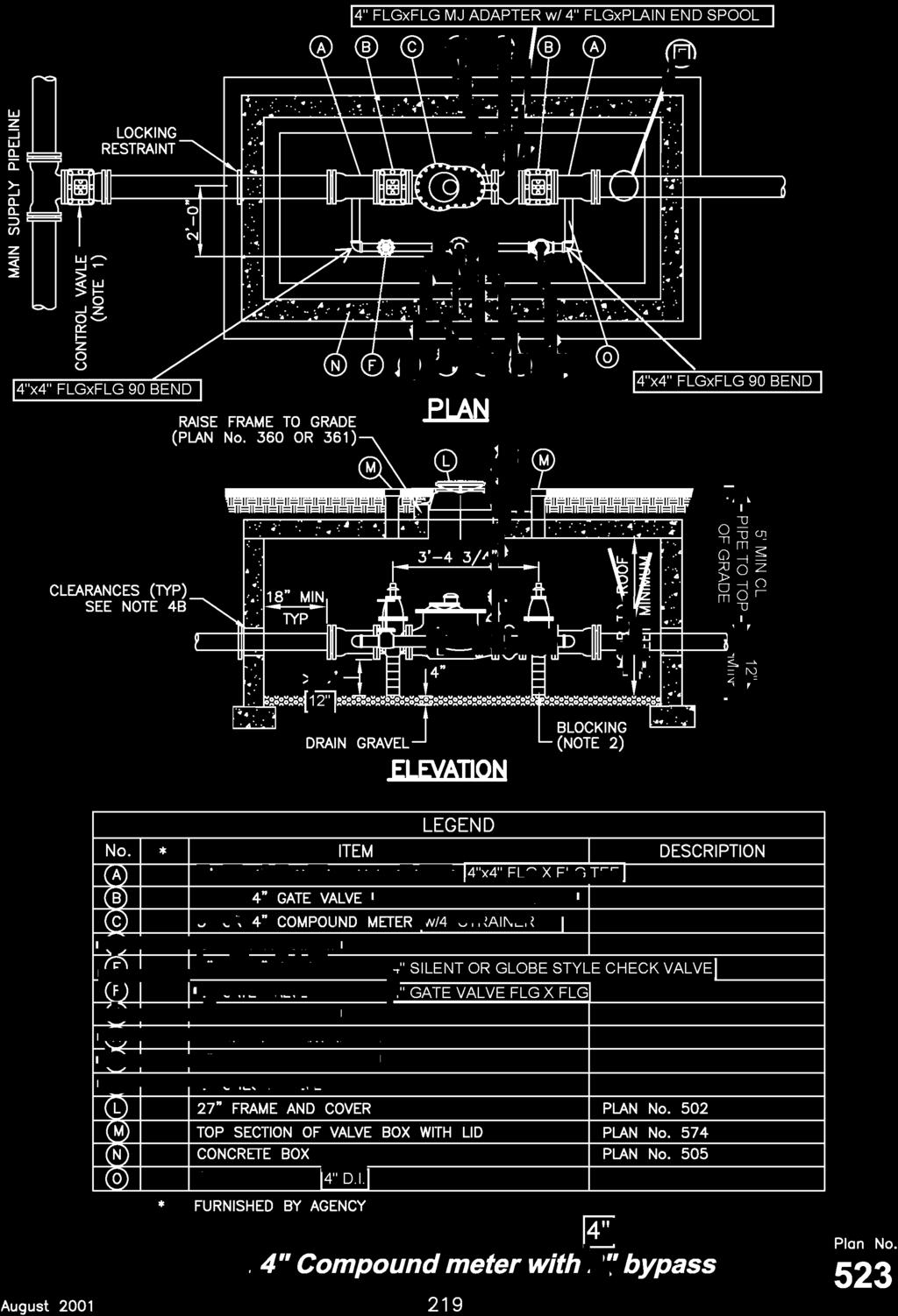
16 3" and 4" Compound meter with 2" bypass 1. CONTROL VALVE: Install valve with valve box adjacent to main. 2. BLOCKING: Clay brick or concrete block. 3. SMALL FITTINGS: Provide brass fittings and nipples. Do not use galvanized materials. 4. CONCRETE BOX: Plan No. 505 A. Center frame and cover over water meter. B. Allow 1 inch clearance around waterline where line passes through wall. Seal opening with compressible seal. 218
17
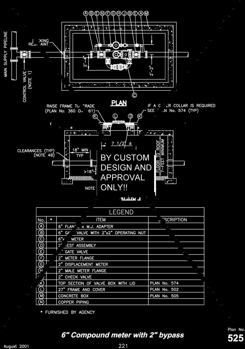
18 6" Compound meter with 2" bypass 1. CONTROL VALVE: Install valve with valve box adjacent to main. 2. BLOCKING: Clay brick or concrete block. 3. SMALL FITTINGS: Provide brass fittings and nipples. Do not use galvanized materials. 4. CONCRETE BOX: Plan No A. Center frame and cover over water meter. B. Allow 1 inch clearance around waterline where line passes through wall. Seal opening with compressible seal. 220

19
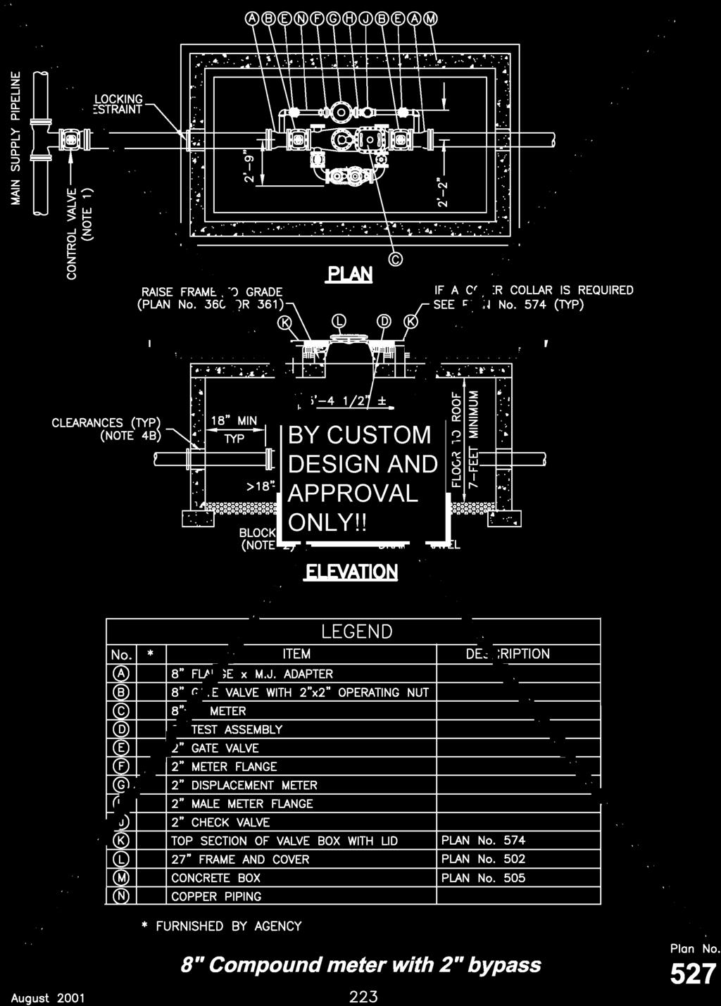
20 8" Compound meter with 2" bypass 1. CONTROL VALVE: Install valve with valve box adjacent to main. 2. BLOCKING: Clay brick or concrete block. 3. SMALL FITTINGS: Provide brass fittings and nipples. Do not use galvanized materials. 4. CONCRETE BOX: Plan No A. Center frame and cover over water meter. B. Allow 1 inch clearance around waterline where line passes through wall. Seal opening with compressible seal. 222
21
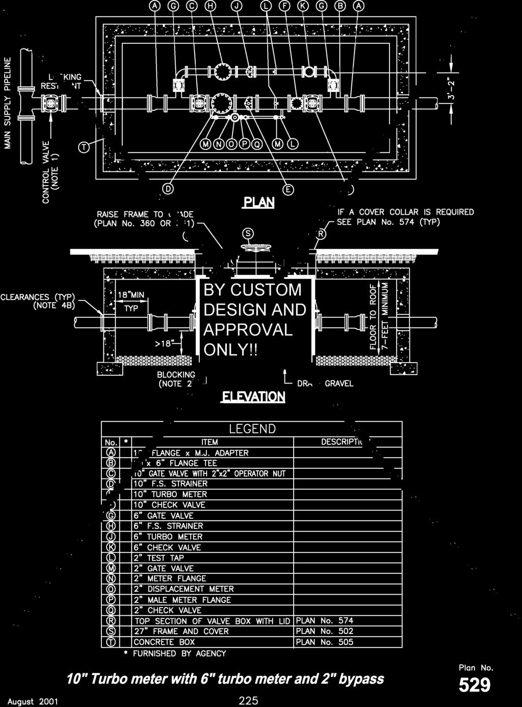
22 10" Turbo meter with 6" turbo meter and 2" bypass 1. CONTROL VALVE: Install valve with valve box adjacent to main. 2. BLOCKING: Clay brick or concrete block. 3. SMALL FITTINGS: Provide brass fittings and nipples. Do not use galvanized materials. 4. CONCRETE BOX: Plan No A. Center frame and cover over water meter. B. Allow 1 inch clearance around waterline where line passes through wall. Seal opening with compressible seal. 224
23
24 Electrolysis monitoring station details 226
25
26 Water service line 1. INSPECTION: Prior to backfilling trench excavation, secure inspection of installation by ENGINEER. 2. BACKFILL: Provide and place per APWA Section Compact per APWA Section to a modified proctor density of 95 percent or greater. Maximum lift thickness is 8 inches before compaction. 3. FITTINGS: Provide brass fittings and nipples. Do not use galvanized materials. 228
27
28 Waterline loop 1. INSPECTION: Prior to backfilling trench excavation, secure inspection of installation by ENGINEER. 2. BACKFILL: Provide and place per APWA Section Compact per APWA Section to a modified proctor density of 95 percent or greater. Maximum lift thickness is 8 inches before compaction. 3. PIPE: Match existing service. Bend pipe around obstruction. 4. THRUST BLOCKS: Not required for flange or welded pipe systems. 5. FITTINGS: Use copper to copper flare fittings or copper to iron pack joint coupling with locking split clamp on iron pipe side and flare on copper side. All couplings to be brass. 6. GREASE: Apply poly-fm grease to all buried metal surfaces. Wrap with 8 mil thick polyethylene sheet and tape wrap. 7. STEEL SPOOL: Weld in place and provide slip on flange except when fitting in pipe system could move. Epoxy line per AWWA C210, AWWA C213, and coated per AWWA C208, or AWWA C LOCATION: Loop water mains over top of sewer lines. 230
29
30 Fire hydrant replacement or relocation 1. INSPECTION: Prior to backfilling trench excavation, secure inspection of installation by ENGINEER. 2. BACKFILL: Provide and place per APWA Section Compact per APWA Section to a modified proctor density of 95 percent or greater. Maximum lift thickness is 8 inches before compaction. 3. TEMPORARY THRUST BLOCKING: Use wood. 4. VALVE BOXES: Salvage any C.I.S.T. valve boxes and reuse. Adjust to grade as necessary on relocated hydrant. 5. PIPING: Match existing pipe, fittings and coupling sizes and materials. 6. ADJUSTMENTS: Adjust hydrant to grade with hydrant extensions if necessary. 7. CONNECTIONS: If existing valve and hydrant have O.B. connections, delete MJ x Flange adapter and install 6 inch MJ sleeve. 232
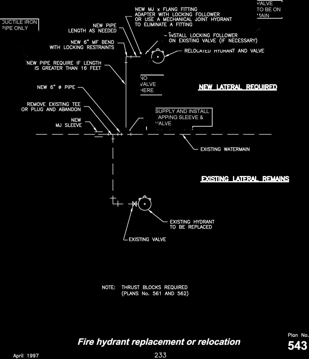
31
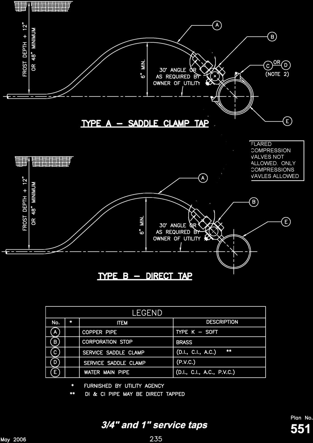
32 3/4" and 1" service taps 1. TAPPING: Place taps a minimum of 24 inches apart. Use a tapping tool that is sized corresponding to the size of the service line to be installed. No taps within 24 inches of end of pipe. 2. PVC OR AC PIPE: A service saddle clamp is required on all PVC and AC pipe taps unless specified otherwise. 3. TAPE: Teflon tape is required on all taps. 4. INSPECTION: Prior to backfilling around taps, secure inspection of installation by ENGINEER. 5. BACKFILL: Provide and place per APWA Section Compact per APWA Section to a modified proctor density of 95 percent or greater. Maximum lift thickness is 8 inches before compaction. 234
33
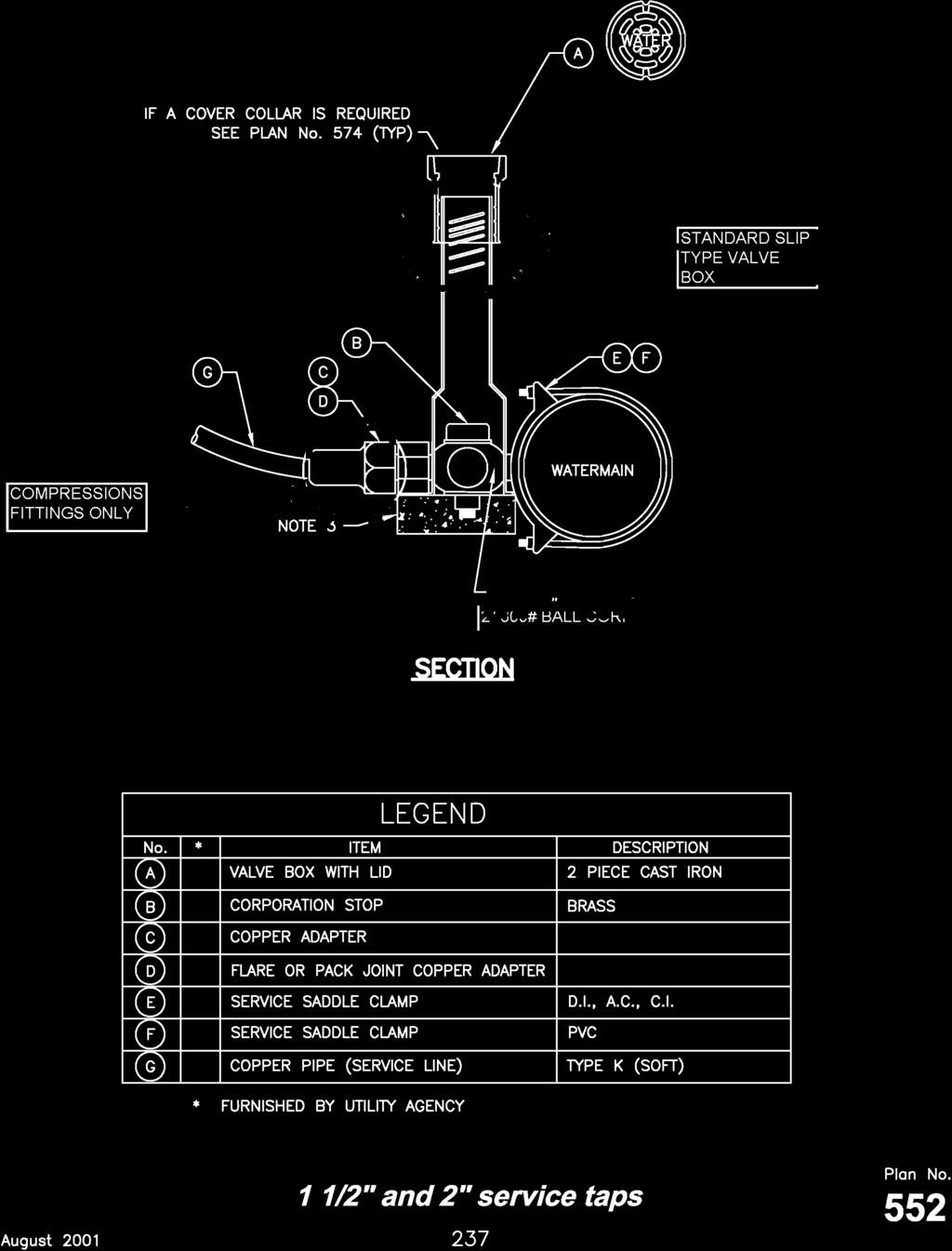
34 1 1/2" and 2" service taps 1. TAPPING: Place taps a minimum of 24 inches apart. Use a tapping tool that is sized corresponding to the size of the service line to be installed. No taps within 24 inches of end of pipe. 2. TAPE: Teflon tape is required on all taps. 3. BLOCKS: Clay brick or concrete block required under valve box to assure a 1" space before bearing on a corporation stop. 4. SADDLE CLAMP: Required on all taps. 5. INSPECTION: Prior to backfilling around taps, secure inspection of installation by ENGINEER. 6. BACKFILL: Provide and place per APWA Section Compact per APWA Section to a modified proctor density of 95 percent or greater. Maximum lift thickness is 8 inches before compaction. 236
35
36 Direct bearing thrust block 1. CONCRETE: Class 2000 minimum per APWA Section Pour concrete against undisturbed soil. 2. PIPE JOINTS: Do not cover with concrete. Leave completely accessible. 3. GREASE: Apply poly-fm grease to all buried metal surfaces. Wrap with 8 mil thick polyethylene sheet and tape wrap. 4. SPECIAL CONSTRUCTION REQUIREMENTS: A. Thrust design for pipe sizes or configurations not shown require special design. B. Bearing areas, volumes, and special thrust blocking details shown on Drawings take precedence over this plan. C. Reinforcing steel bars to be epoxy coated at least 15 mils thick. Minimum stress yield strength of tie down bars is 70,000 psi. D. Locking restraint devices may be used in conjunction with concrete thrust blocking (at option of ENGINEER). 5. INSPECTION: Prior to backfilling around thrust block, secure inspection of installation by ENGINEER. 6. BACKFILL: Provide and place per APWA Section Compact per APWA Section to a modified proctor density of 95 percent or greater. Maximum lift thickness is 8 inches before compaction. 238
37
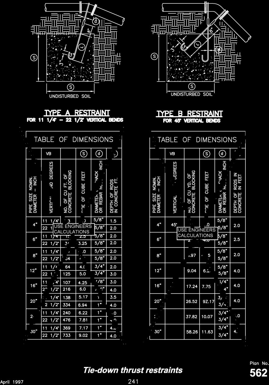
38 Tie-down thrust restraints 1. CONCRETE: Class 2000 minimum per APWA Section Pour concrete against undisturbed soil. 2. PIPE JOINTS: Do not cover with concrete. Leave completely accessible. 3. GREASE: Apply poly-fm grease to all buried metal surfaces. Wrap with 8 mil thick polyethylene sheet and tape wrap. 4. SPECIAL CONSTRUCTION REQUIREMENTS: A. Thrust design for pipe sizes or configurations not shown require special design. B. Bearing areas, volumes, and special thrust blocking details shown on drawings take precedence over this plan. C. Reinforcing steel bars to be epoxy coated at least 15 mils thick. Minimum stress yield strength of tie down bars is 70,000 psi. D. Locking restraint devices may be used in conjunction with concrete thrust blocking (at option of ENGINEER). E. Restraint sizing is based upon a maximum operating pressure of 150 psi and a test pressure of 200 psi, and a minimum soil bearing stress of 2,000 psf. Operating pressures in excess of 150 psi or soils with less than 2,000 pound bearing strength will require special design. F. Concrete must be allowed to cure in thrust restraints for 5 days prior to pressurizing water lines or have additional approved thrust restraints installed prior to pressurizing the water line. 5. INSPECTION: Prior to backfilling around thrust block, secure inspection of installation by ENGINEER. 6. BACKFILL: Provide and place per APWA Section Compact per APWA Section to a modified proctor density of 95 percent or greater. Maximum lift thickness is 8 inches before compaction. 240
39
40 2" washout valve 1. CONCRETE: Class 2000 minimum per APWA Section Pour concrete against undisturbed soil. 2. TAPE: Apply tape wrap to the exterior of all galvanized pipe per AWWA C SPECIAL DESIGN: Watermains 12" and larger will require special washout assembly design. 4. DRAINAGE: After installation of washout valve assembly, verify the washout valve riser drains to gravel. 5. INSPECTION: Prior to backfilling around thrust block, secure inspection of installation by ENGINEER. 6. BACKFILL: Provide and place per APWA Section Compact per APWA Section to a modified proctor density of 95 percent or greater. Maximum lift thickness is 8 inches before compaction. 242
41
42 Detector check valve with 3/4" bypass meter 1. CONTROL VALVE: Install valve with valve box adjacent to main. 2. BLOCKING: Clay brick or concrete block. 3. SMALL FITTINGS: Provide brass fittings and nipples. Do not use galvanized materials. 4. CONCRETE BOX: A. Center frame and cover over water meter. B. Allow 1 inch clearance around waterline where line passes through wall. Seal opening with compressible seal. 5. GRADE RING: 6 inch concrete grade ring required in roadways. See Plan No SPOOLS: Length of flange x plain end spool varies. Pipe size SPOOLS Pipe length 6" 10" 8" 8 1/4" 10" 6" 7. VALVE OPTION: The valve in the box (item B legend) closest to the main, and the top section of the valve box (item J legend) may be eliminated at the option of the ENGINEER 244
43
44 6" Pressure reducing valve with 2" bypass 1. SMALL FITTINGS: Provide brass fittings and nipples. Do not use galvanized materials. 2. BLOCKING: Clay brick or concrete block. 3. TAPS: Provide two 3/4" I.P. taps with plugs for pressure gages. 4. CONCRETE BOX: A. Center frame and cover over water meter. B. Allow 1 inch clearance around waterline where line passes through wall. Seal opening with compressible seal. 246
45
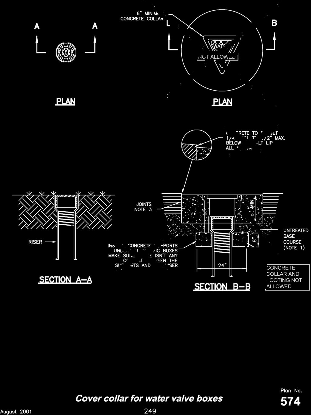
46 Cover collar for water valve boxes 1. UNTREATED BASE COURSE: Provide material specified in APWA Section Do not use pea gravel or sewer rock. Place per APWA Section Compact per APWA Section to a modified proctor density of 95 percent or greater. Maximum lift thickness is 8 inches before compaction. 2. CONCRETE: Class 4000 per APWA Section Place concrete per APWA Section Cure per APWA Section JOINTS: Provide a neat straight joint between existing and new asphalt concrete surfaces. Provide concentric circle cut. Clean edges of all dirt, oil and loose debris. 248
47
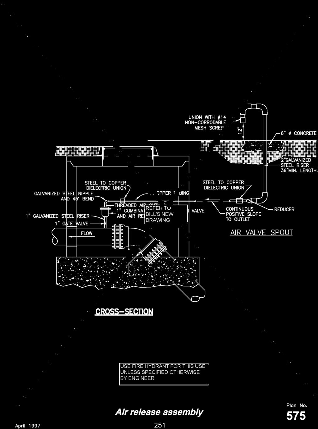
48 Air release assembly 1. CONCRETE: Class 4000 per APWA Section Place concrete per APWA Section Cure per APWA Section SMALL FITTINGS: Provide brass fittings and nipples if not specified otherwise. Do not use galvanized materials. 3. INSPECTION: Prior to backfilling around the assembly, secure inspection of installation by ENGINEER. 4. BACKFILL: Provide and place per APWA Section Compact per APWA Section to a modified proctor density of 95 percent or greater. Maximum lift thickness is 8 inches before compaction. 250
49
50 Pressurized irrigation water and potable water interface 1. AIR GAP: An air gap of at least two pipe diameters must exist between the maximum overflow lip of the catch basin and the end of the down-turned discharge pipe. 2. STOP AND WASTE VALVE: Locate the valve in an area where subsurface ground water will not accumulate or attach a drain pipe to the drain hole and drain to daylight with a non-corrodible #14 mesh screen over the end. 3. CATCH BASIN: The ground surrounding the catch basin must slope away from the catch basin (basin cannot be located where flooding could result in a water level higher than the maximum overflow lip of the catch basin). 4. STAND PIPES: Provide draining and freeze protection. 5. SOLENOID VALVE: A solenoid operated valve may be installed at this point provided the valve and housing are not constructed of plastic (must be brass or ferrous metal). 6. SYSTEM DESIGN: The catch basin valve and pump size must match the minimum discharge rate from the potable water system when indoor demands are also being expected from the system. 7 PIPING MATERIALS: A. All parts of the potable water system from the stop and waste valve to the air gap drop leg above the catch basin are to be copper or galvanized iron only. B. Below ground parts on the non-potable water system may be made of PVC or polyethylene at the owner's discretion. 252
51
52 Pressurized irrigation water and potable water interface 1. SEPARATE SYSTEMS: Connect hose to only one system at a time. The other system is to remain separate. Do not direct connect potable and non-potable water systems with or without backflow prevention devices. 2. STOP AND WASTE VALVE: Locate the valve in an area where subsurface ground water will not accumulate, or attach a drain pipe to the drain hole and drain to daylight with a non-corrodible #14 mesh screen over the end. 3. TESTING: The reduced pressure backflow preventer (RPBP) device requires testing within 10 days of initial installation by a licensed backflow device tester and annually thereafter or more frequently at owner's option and expense. 4. BACKFLOW PREVENTER: Install the RPBP device above ground per the plumbing code. It mast not be susceptible to flooding and must be accessible at all times for testing, repair, inspection, etc. 5. STAND PIPES: Provide draining and freeze protection. 6. SYSTEM DESIGN: There may be up to 20 psi loss of head through the RPBP device. this is normal and the owner should expect a decrease in area coverage. Owner should design or modify the system for the lower pressure. 7 PIPING MATERIALS: A. All above ground parts are to be copper or galvanized iron only. B. Below ground parts on the non-potable water system may be made of PVC or polyethylene at the owner's discretion. 8. CAM LOCK FITTINGS: Provide 3/4" long male insert attached to the flexible hose. RPBP = reduced pressure backflow preventer 254
53
54 256
ADDENDUM NO. 1. Mallory Valley Utility District Technical Specifications & Design Criteria for Water Supply & Distribution Facilities
 ADDENDUM NO. TO Mallory Valley Utility District Technical Specifications & Design Criteria for Water Supply & Distribution Facilities Date of Addendum: December, 00 Hethcoat & Davis, Inc. 78 Franklin Road,
CITY OF WARRENVILLE STANDARD SPECIFICATIONS WATER MAIN, SANITARY SEWER AND STORM SEWER
 CITY OF WARRENVILLE STANDARD SPECIFICATIONS WATER MAIN, SANITARY SEWER AND STORM SEWER WATER MAIN 1. All open cut water main shall be polyvinyl chloride plastic (PVC) pressure pipe per AWWA specification
PART 7 COMMUNICATIONS, LIGHTING, TRAFFIC CONTROL, POWER
 PART 7 COMMUNICATIONS, LIGHTING, TRAFFIC CONTROL, POWER COMMUNICATIONS LIGHTING Street Lighting Plan 710 Riser... 287 730 Collar for street light pole... 289 731 Pull box... 291 732 Trench for street light
SECTION 2100 WATER MAIN
 SECTION 2100 WATER MAIN WATER MAIN PART 1 GENERAL 1.01 Section Summary A. This section includes product and installation requirements for water main pipe, gate valves, hydrants, fittings, and miscellaneous
SECTION STORM DRAINAGE
 SECTION 02720 STORM DRAINAGE PART 1 - GENERAL 1.01 WORK INCLUDED A. Trenching and other excavation. B. Ground water control. C. Pipe bedding. D. Installation of storm drains and appurtenances. E. Installation
Underground Piping for Private Hydrants & Sprinkler Supply Line
 City of Brea Brea Fire Department Fire Prevention 1 Civic Center Circle Phone: (714) 990-7655 Underground Piping for Private Hydrants & Sprinkler Supply Line PURPOSE The provision of adequate water supplies
Amendments to the January 2016 Design Criteria Manual & Supplementary Master Municipal Construction Documents
 General Figure 2.3.1 16 Revise Revised Figure 2.3.1: New Development Areas where Secondary Suites Apply to include two new areas (#4 and 5). Water 3.3.2 Watermains 31 Add Added wording in Section 3.3.2.3
SECTION 39 - MANHOLES TABLE OF CONTENTS
 Section SECTION 39 - MANHOLES TABLE OF CONTENTS Page 39-1 GENERAL... 39.1 39-2 CONCRETE MANHOLES... 39.1 39-2.01 NOT USED... 39.1 39-2.02 Concrete Storm Drain Manholes... 39.1 39-3 SADDLE SEWER MANHOLES...
SECTION WATER SERVICE CONNECTIONS
 SECTION 33 12 13 WATER SERVICE CONNECTIONS PART 1 GENERAL 1.1 SUMMARY A. Section Includes: 1. Pipe and fittings for domestic water service connections to buildings. 2. Corporation stop assembly. 3. Curb
SUB WATER DEPARTMENT STANDARD CONSTRUCTION SPECIFICATIONS TABLE OF CONTENTS SECTION POLYETHYLENE PRESSURE PIPE
 SUB WATER DEPARTMENT STANDARD CONSTRUCTION SPECIFICATIONS TABLE OF CONTENTS SECTION 33 11 13.24 POLYETHYLENE PRESSURE PIPE PART 1 GENERAL... 2 1.1 Description... 2 1.2 Reference Specification... 2 1.3
SECTION PUBLIC WATER SERVICE CONNECTIONS
 SECTION 33 14 14 PUBLIC WATER SERVICE CONNECTIONS PART 1 GENERAL 1.1 SUMMARY A. Section Includes: 1. Pipe and fittings for water service connections to small commercial, light industrial, and residential
Section 403. DRAINAGE STRUCTURES
 403.01 Section 403. DRAINAGE STRUCTURES 403.01. Description. This work consists of adjusting, constructing, or temporarily lowering drainage structures and cleaning existing drainage structures and leads
San Antonio Water System Standard Specifications for Construction ITEM NO. 824 SERVICE SUPPLY LINES (WATER)
") San Antonio Water System Standard Specifications for Construction ITEM NO. 824 SERVICE SUPPLY LINES (WATER) 824.1 DESCRIPTION: This item shall consist of water service supply lines adjustment and installation
San Antonio Water System Standard Specifications for Construction ITEM NO. 824 SERVICE SUPPLY LINES (WATER) 824.1 DESCRIPTION: This item shall consist of water service supply lines adjustment and installation
ONE PIPE LENGTH MAX (REFER TO 1/4"/FT SLOPE (MIN) 5'-0" (MIN) OR 4" LATERAL NOTE #1) INCREASER RIGHT-OF-WAY/ 4"x6" REFER TO TYPICAL EXCAVATION,
 5'-0 (MIN) OR 4 LATERAL NOTE #1) INCREASER RIGHT-OF-WAY/ 4x6 REFER TO TYPICAL EXCAVATION,") VENT CAP (MUSHROOM TYPE) SOLID CAP EXIST GRADE MIN BUILDING REFER TO NOTE #4 MIN CONCRETE SIDEWALK CURB OR EDGE OF SIDEWALK STREET CLEANOUT (REFER TO NOTE #3) VENT PIPE 4" PVC 6" PVC CLEANOUT CONCRETE
VENT CAP (MUSHROOM TYPE) SOLID CAP EXIST GRADE MIN BUILDING REFER TO NOTE #4 MIN CONCRETE SIDEWALK CURB OR EDGE OF SIDEWALK STREET CLEANOUT (REFER TO NOTE #3) VENT PIPE 4" PVC 6" PVC CLEANOUT CONCRETE
SECTION 8 SEPARATION OF LINES
 SECTION 8 SEPARATION OF LINES 8.01 INDEX 8.01 INDEX 8.02 PURPOSE 8.03 DEFINITIONS 8.04 SEWER SEPARATION 8.05 NON-POTABLE SEPARATION 8.06 REFERENCES 8.02 PURPOSE This section states the requirements and
Ice Rink Renovation & New Clubhouse
 SECTION 331213 - WATER SERVICE CONNECTIONS PART 1 GENERAL 1.1 SUMMARY A. Section Includes: 1. Pipe and fittings for domestic water service connections to buildings. 2. Corporation stop assembly. 3. Curb
A. Gravity-Flow, Nonpressure, Drainage-Piping Pressure Rating: 10-foot head of water (30 kpa).
.") SECTION 221313 - FACILITY SANITARY SEWERS PART 1 - GENERAL 1.1 RELATED DOCUMENTS A. Drawings and general provisions of the Contract, including General and Supplementary Conditions and Division 01 Specification
SECTION 221313 - FACILITY SANITARY SEWERS PART 1 - GENERAL 1.1 RELATED DOCUMENTS A. Drawings and general provisions of the Contract, including General and Supplementary Conditions and Division 01 Specification
CHINO VALLEY FIRE DISTRICT FIRE PROTECTION STANDARD
 CHINO VALLEY FIRE DISTRICT FIRE PROTECTION STANDARD SPECIFICATIONS Establishing Minimum Standards for as Related To Fire Protection STANDARD # 103 REVISED 04/01/19 PAGES 7 SCOPE: These specifications shall
ITEM NO. 824 SERVICE SUPPLY LINES (WATER)
") ITEM NO. 824 SERVICE SUPPLY LINES (WATER) 824.1 DESCRIPTION: This item shall consist of water service supply lines installation and adjustment installed in accordance with these specifications and as directed
ITEM NO. 824 SERVICE SUPPLY LINES (WATER) 824.1 DESCRIPTION: This item shall consist of water service supply lines installation and adjustment installed in accordance with these specifications and as directed
SECTION MEASUREMENT AND PAYMENT
 SECTION 01026 PART 1 GENERAL 1.1 SECTION INCLUDES A. Explanation and Definitions B. Measurement C. Payment D. Schedule of Values E. Application for Payment 1.2 EXPLANATION AND DEFINITIONS A. The following
YAKIMA COUNTY, WASHINGTON. Special Provisions For Water Main Construction
 YAKIMA COUNTY, WASHINGTON Special Provisions For Water Main Construction The 2014 Standard Specifications for Road, Bridge, and Municipal Construction as prepared by the Washington State Department of
Amendment to OPSS 493 (Nov 2015) Construction Specification for Temporary Potable Water Supply Services
 Construction Specification for Temporary Potable Water Supply Services") Engineering & Construction Services Division Standard Specifications for Sewers and Watermains TS 493 September 2017 Amendment to OPSS 493 (Nov 2015) Construction Specification for Temporary Potable Water
Engineering & Construction Services Division Standard Specifications for Sewers and Watermains TS 493 September 2017 Amendment to OPSS 493 (Nov 2015) Construction Specification for Temporary Potable Water
A. This Section includes gravity-flow, nonpressure storm drainage outside the building, with the following components:
 SECTION 334100 - STORM UTILITY DRAINAGE PIPING PART 1 - GENERAL 1.I RELATED DOCUMENTS A. Drawings and general provisions of the Contract, including General and Supplementary Conditions and Division 1 Specification
DRINKING WATER LINE INSTALLATION STANDARDS
 30" MIN. 72" MAX. ORIGINAL GROUND SURFACE BACKFILL WITH A-1-a OR NATIVE MATERIAL PER APWA STANDARDS. MATERIAL MUST MEET APWA STANDARD FOR GRANULAR BORROW. COMPACT BACKFILL ABOVE PIPE ZONE TO 96% DENSITY
CONSTRUCTION SPECIFICATION FOR THE INSTALLATION OF ELECTRICAL CHAMBER
 ONTARIO PROVINCIAL STANDARD SPECIFICATION METRIC OPSS 602 MARCH 1993 CONSTRUCTION SPECIFICATION FOR THE INSTALLATION OF ELECTRICAL CHAMBER 602.01 SCOPE 602.02 REFERENCES 602.05 MATERIALS TABLE OF CONTENTS
SECTION UTILITY POLYETHYLENE CONTAINMENT PIPE SYSTEMS
 SECTION 02670 UTILITY POLYETHYLENE CONTAINMENT PIPE SYSTEMS PART 1 - GENERAL 1.01 WORK INCLUDED A. Trenching and other excavation. B. Ground water control. C. Pipe bedding. D. Installation of containment
CITY of DALLAS. Standard Drawings. & Oregon Standard Drawing Amendments. Water Drawings
 CITY of DALLAS Standard Drawings & Oregon Standard Drawing Amendments Water Drawings RD250 - Thrust Blocking RD254 - Hydrant Installation RD258 - Valve Box and Operator Extension Assembly RD262 - Standard
VALLECITOS WATER DISTRICT SECTION PRECAST REINFORCED CONCRETE MANHOLES
 PART 1 GENERAL 1.1 DESCRIPTION A. This section includes materials, testing, and installation of precast concrete manholes, manhole bases, manhole frames, and covers. 1.2 RELATED WORK SPECIFIED ELSEWHERE
SECTION 39 - MANHOLES TABLE OF CONTENTS 39-1 GENERAL PRECAST CONCRETE MANHOLES
 Section SECTION 39 - MANHOLES TABLE OF CONTENTS 39-1 GENERAL... 39-1 39-2 PRECAST CONCRETE MANHOLES... 39-1 39-2.01 Precast Concrete Storm Drain Manholes... 39-1 39-3 SADDLE MANHOLES... 39-2 39-3.01 Saddle
Water & Industrial Products Catalog
 Water & Industrial Products Catalog www.smith-blair.com info@smith-blair.com Phone: 800..9705 or 870.77.527 After Hours Number: 90.277.998 Fax: 800.8.792 or 870.77.52 EMERGENCY PHONE 90.277.998 In the
TECHNICAL SPECIAL PROVISION FOR FINANCIAL PROJECT ID:
 TECHNICAL SPECIAL PROVISION FOR 1001 WATER DISTRIBUTION SYSTEM FINANCIAL PROJECT ID: 200105-7-52-01 The official record of this Technical Special Provision is the electronic file signed and sealed under
SECTION SANITARY SEWERAGE PART 1 GENERAL 1.01 RELATED DOCUMENTS
 SECTION 02530 - SANITARY SEWERAGE PART 1 GENERAL 1.01 RELATED DOCUMENTS A. Drawings and general provisions of the Contract, including General and Supplementary Conditions and Division 1 Specification Sections,
CONSTRUCTION SPECIFICATION FOR TEMPORARY POTABLE WATER SUPPLY SERVICES
 ONTARIO PROVINCIAL STANDARD SPECIFICATION METRIC OPSS 493 NOVEMBER 2015 CONSTRUCTION SPECIFICATION FOR TEMPORARY POTABLE WATER SUPPLY SERVICES TABLE OF CONTENTS 493.01 SCOPE 493.02 REFERENCES 493.03 DEFINITIONS
PASSAIC COUNTY TECHNICAL INSTITUTE CCA 1422 NEW S.T.E.M. BUILDING 2017
 SECTION 02630 - STORM DRAINAGE PART 1 - GENERAL 1.1 RELATED DOCUMENTS A. Drawings and general provisions of the Contract, including General and Supplementary Conditions and Division 01 Specification Sections,
CONSTRUCTION SPECIFICATION FOR TEMPORARY POTABLE WATER SUPPLY SERVICES
 ONTARIO PROVINCIAL STANDARD SPECIFICATION METRIC OPSS 493 NOVEMBER 2009 (Reissued November 2010) CONSTRUCTION SPECIFICATION FOR TEMPORARY POTABLE WATER SUPPLY SERVICES TABLE OF CONTENTS 493.01 SCOPE 493.02
San Antonio Water System Standard Specifications for Construction ITEM NO. 812 WATER MAIN INSTALLATION
 ITEM NO. 812 WATER MAIN INSTALLATION 812.1 DESCRIPTION: This item shall consist of water main installation in accordance with these specifications and as directed by the Engineer. 812.2 MATERIALS: The
East Wenatchee Water District Supplemental Provisions to the 2012 WSDOT/APWA Standard Specifications
 East Wenatchee Water District Supplemental Provisions to the 2012 WSDOT/APWA Standard Specifications 1-01 DEFINITIONS and TERMS 1-01.3 Definitions This section is supplemented with the following Deleted
CLEVELAND DIVISION OF WATER CONSTRUCTION STANDARDS. Details Index
 CLEVELAND DIVISION OF WATER CONSTRUCTION STANDARDS Details Index PLAN REVIEW AND DESIGN REQUIREMENTS SERVICE CONNECTION REQUIREMENTS EASEMENTS FOR WATER SUPPLY MAINS, CIRCULATION MAINS, AND VAULTS HYDRANT
San Antonio Water System Standard Specifications for Construction ITEM NO. 813 WATER SERVICE FOR FIRELINES
 ITEM NO. 813 WATER SERVICE FOR FIRELINES 813.1 DESCRIPTION: This item shall consist of water service for fire line installations in accordance with these specifications and as directed by the Engineer.
SUPPLEMENTAL SPECIFICATIONS AND DRAWINGS TO THE IDAHO STANDARDS FOR PUBLIC WORKS CONSTRUCTION TABLE OF CONTENTS
 PREFACE AND CITY ENGINEER S LETTER INDEX OF STANDARD DRAWINGS DIVISION 100 GENERAL CONDITIONS ARTICLE 1 DEFINITIONS AND TERMINOLOGY 1.01 Defined Terms ARTICLE 2 PRELIMINARY MATTERS 2.01 Delivery of Bonds
City of Port Moody. Water Meter Specifications
 City of Port Moody Water Meter Specifications Engineering Division, Updated December 2015 City of Port Moody Water Meter Specifications 1. Preamble... 3 2. Definitions... 3 3. Services to be Metered...
CITY OF LA MARQUE, TEXAS CHAPTER 3 WATER SYSTEM DESIGN CRITERIA
 CITY OF LA MARQUE, TEXAS CHAPTER 3 WATER SYSTEM DESIGN CRITERIA CHAPTER 3 WATER SYSTEM DESIGN 3.1 WATER SYSTEM DESIGN GENERAL 3.1.1 Criteria for the design of water service and water distribution lines
SANITARY SEWERS. B. Construct or relocate building sanitary sewer services, stubs, and connections.
 SANITARY SEWERS PART 1 - GENERAL 1.01 SECTION INCLUDES A. Sanitary Sewer Gravity Mains B. Sanitary Sewer Force Mains C. Sanitary Sewer Services 1.02 DESCRIPTION OF WORK A. Construct sanitary sewer gravity
f. GREEN VALLEY WATER SUPPLY CORP. ( )
") GENERAL WATER NOTES L:\Engineer\Standard Details and Technical Specifications\Standard Details\201\STANDARD WATER DETAILS 0223201.dwg 1. ALL MATERIALS AND CONSTRUCTION PROCEDURES WITHIN SCOPE THIS PROJECT
GENERAL WATER NOTES L:\Engineer\Standard Details and Technical Specifications\Standard Details\201\STANDARD WATER DETAILS 0223201.dwg 1. ALL MATERIALS AND CONSTRUCTION PROCEDURES WITHIN SCOPE THIS PROJECT
CHAPTER 3 - PRESSURE IRRIGATION
 CHAPTER 3 - PRESSURE IRRIGATION 3.1 GENERAL This division covers furnishing and installing pressure pipe as shown on the Drawings or established in the field, and all flushing, testing, repairing, as required
Copper-Type K soft Drawn 40, 50 HDPE 100 and larger
 1.0 GENERAL 1.1 Scope 1.1.1 The work covered by this section involves the installation of water and sewer service connections and all other associated work. 1.2 Authorization 1.2.1 Do not install service
SECTION WATER MAINS CITY OF LEE S SUMMIT, MISSOURI DESIGN CRITERIA
 SECTION 6900 - WATER MAINS CITY OF LEE S SUMMIT, MISSOURI DESIGN CRITERIA 6901 DESIGN CRITERIA A. General 1. The design standards presented in the City of Lee's Summit Design Criteria are the minimum standards
Drainage structure refers to manholes, catch basins, leaching basins, inlets and drop inlets. Drainage structures are designated as follows.
 403.01 Section 403. DRAINAGE STRUCTURES 403.01 Description. Adjust, construct, or temporarily lower drainage structures. Clean existing drainage structures and leads as directed by the Engineer. Drainage
SECTION MINOR CONCRETE
 SECTION 03300 - MINOR CONCRETE CONTENTS: Part 1 - General... 1 1.01 Work Included... 1 1.02 Related Requirements... 1 1.03 Reference Standards... 1 1.04 Quality Assurance... 1 1.05 Measurement And Payment...
UNIVERSITY OF MISSOURI Hydronic Energy Distribution 2016 Q1
 GENERAL: The scope of this document is to provide instruction for the installation and testing of chilled water piping installed for the University of Missouri. DESIGN GUIDELINES: 1. Materials 1.1. Pipe
DIVISION 33 UTILITIES
 DIVISION 33 UTILITIES This Article on Codes, Regulation and Standards shall apply to all Divisions of the Building Standards Table of Contents 33 05 13 MANHOLES AND STRUCTURES... 3 33 10 00 WATER UTILITIES...
Public Water Supply District #2 of St. Charles County, Missouri
 Public Water Supply District #2 of St. Charles County, Missouri POLICIES, PROCEDURES, AND REQUIREMENTS FOR CONNECTION AND INSPECTIONS OF: RESIDENTIAL WATER AND/OR SEWER SERVICE CONNECTIONS COMMERCIAL WATER
TABLE OF CONTENTS
 DIVISION 33: SEWER AND SEPTIC SYSTEMS 33 3633 UTILITY SEPTIC TANK DRAINAGE FIELD TABLE OF CONTENTS 33 0000-1 SECTION 33 3633-- UTILITY SEPTIC TANK DRAINAGE FIELD PART 1 - GENERAL 1.1 SUMMARY A. Includes
SECTION 5 INSTALLATION OF DUCTILE IRON AND PVC PIPE, VALVES, FITTINGS, FIRE HYDRANTS, AND APPURTENANCES
 SECTION 5 INSTALLATION OF DUCTILE IRON AND PVC PIPE, VALVES, FITTINGS, FIRE HYDRANTS, AND APPURTENANCES 5-01 GENERAL Unless specified differently on the plans or as supplemented herein, installation of
SECTION FIRE HYDRANTS
 SECTION 21 11 10 PART 1. GENERAL 1.1 SUMMARY: A. Work consists of furnishing and installing new fire hydrants, (boot with ductile iron retainer gland, standpipe and hydrant complete) plus constructing
ADDENDUM NO. 1 TO THE TENDER DOCUMENTS FOR THE CORPORATION OF THE CITY OF PENTICTON 2017-Tender Capital Works
 ADDENDUM NO. 1 TO THE TENDER DOCUMENTS FOR THE CORPORATION OF THE CITY OF PENTICTON - April 24, 2017 To All Tenderers: This Addendum is issued prior to the Tender Closing Date April 25, 2017 in accordance
Section 401. PIPE CULVERTS
 401.02 Section 401. PIPE CULVERTS 401.01. Description. This work consists of constructing pipe culverts of the size and class required, including excavation and backfill. 401.02. Materials. Provide materials
TCC/SHORE TRANSIT BUS MAINTENANCE FACILITY - PHASE II
 SECTION 221313 - FACILITY SANITARY SEWERS PART 1 - GENERAL 1.1 RELATED DOCUMENTS A. Drawings and general provisions of the Contract, including General and Supplementary Conditions and Division 01 Specification
SECTION UNDERGROUND ELECTRICAL CONSTRUCTION
 PART 1 - GENERAL 1.1 DESCRIPTION SECTION 26 05 41 UNDERGROUND ELECTRICAL CONSTRUCTION A. This section specifies the furnishing, installation, and connection of precast manholes and pullboxes with ducts
NC State University Design and Construction Guidelines Division 33 Utilities
 1.0 Purpose A. These guidelines provide methods and requirements to ensure that the connections, attachments, extensions, or other site utility modifications meet NC State standards. B. NC State is responsible
RICHFIELD CITY CONSTRUCTION STANDARDS
 CONSTRUCTION STANDARDS REVISED OCTOBER 2015 Jones & DeMille Engineering, Inc. [0711-211] 1535 South 100 West Richfield, UT 84701 Ph. 435-896-8266 Fax 435-896-8268 1675 South Highway 10 Price, UT 84501
ADDENDUM NO. 2 TO THE TENDER DOCUMENTS FOR THE CORPORATION OF THE CITY OF PENTICTON 2015 Capital Works 2015-Tender-02
 ADDENDUM NO. 2 TO THE TENDER DOCUMENTS FOR THE CORPORATION OF THE CITY OF PENTICTON April 28, 2015 To All Tenderers: This Addendum is issued prior to the Tender Closing Date April 30, 2015, in accordance
***************************************************************************************************************
 02732 SANITARY FORCE MAIN *************************************************************************************************************** SPECIFIER: CSI MasterFormat 2004 number 33 34 00. ***************************************************************************************************************
OLYMPIC VIEW WATER AND SEWER DISTRICT APPROVED MATERIALS LIST FOR USE ON NEW CONSTRUCTION OF WATER AND SEWER FACILITIES
 OLYMPIC VIEW WATER AND SEWER DISTRICT APPROVED MATERIALS LIST FOR USE ON NEW CONSTRUCTION OF WATER AND SEWER FACILITIES This form is intended for use by developers or contractors constructing potable water
(SIZE) MANHOLES CATCH BASINS AND DITCH INLETS -Item No. ADJUSTING AND REBUILDING MANHOLES, CATCH BASINS AND DITCH INLETS - Item No.
 MANHOLES CATCH BASINS AND DITCH INLETS -Item No. ADJUSTING AND REBUILDING MANHOLES, CATCH BASINS AND DITCH INLETS - Item No.") (SIZE) MANHOLES CATCH BASINS AND DITCH INLETS -Item No. ADJUSTING AND REBUILDING MANHOLES, CATCH BASINS AND DITCH INLETS - Item No. Special Provision No. 407S06 July 2010 Aggregate Requirements, Lift Rings,
(SIZE) MANHOLES CATCH BASINS AND DITCH INLETS -Item No. ADJUSTING AND REBUILDING MANHOLES, CATCH BASINS AND DITCH INLETS - Item No. Special Provision No. 407S06 July 2010 Aggregate Requirements, Lift Rings,
CITY OF MERCER ISLAND DEVELOPMENT SERVICES GROUP 9611 SE 36TH STREET MERCER ISLAND, WA PHONE:
 CITY OF MERCER ISLAND DEVELOPMENT SERVICES GROUP 9611 SE 36TH STREET MERCER ISLAND, WA 98040 PHONE: 206.275.7605 www.mercergov.org Water Service Installation Procedures 1 Call for utility locates, mark
SECTION 401 WATER PIPE AND FITTINGS 2.2 POLYVINYL CHLORIDE (PVC) PIPE AND FITTINGS
 PIPE AND FITTINGS") SECTION 401 PIPE AND FITTINGS PART 2 MATERIALS 2.2 POLYVINYL CHLORIDE (PVC) PIPE AND FITTINGS A. PVC Pressure Pipe sizes 4 inch through 12 inch: ANSI/AWWA C 900 1. DR18 B. PVC Pressure Pipe sizes 14 inch
SECTION 401 PIPE AND FITTINGS PART 2 MATERIALS 2.2 POLYVINYL CHLORIDE (PVC) PIPE AND FITTINGS A. PVC Pressure Pipe sizes 4 inch through 12 inch: ANSI/AWWA C 900 1. DR18 B. PVC Pressure Pipe sizes 14 inch
B. Fiberglass for construction in back lot easements placed on cast-in-place base.
 Section 02083 PART 1 G E N E R A L 1.01 SECTION INCLUDES A. Fiberglass manholes for unpaved areas placed on top of a precast base to form a manhole. B. Fiberglass for construction in back lot easements
2.1.2 Minimum wall thickness shall be 90 mm Frames and covers shall be bitumen coated by dipping.
 1.0 GENERAL 1.1 Scope 2.0 PRODUCTS 1.1.1 The work shall consist of the construction, renovation or the adjustment of manholes and/or catchbasins as detailed on the plans or where designated by the Engineer
FS-DUO. Wastewater Flow Distributor Technical Data. Submittal Special Precautions Specifications Installation. (62.2 cm) (62.2 cm)
 (62.2 cm)") Wastewater Flow Distributor Technical Data Submittal Special Precautions Specifications Installation 24½" (62.2 cm) 12½" (31.8 cm) 24½" (62.2 cm) (30.5 cm) SUBMITTAL STANDARD: 4" plain end inlet/outlet
Wastewater Flow Distributor Technical Data Submittal Special Precautions Specifications Installation 24½" (62.2 cm) 12½" (31.8 cm) 24½" (62.2 cm) (30.5 cm) SUBMITTAL STANDARD: 4" plain end inlet/outlet
BUILDING SEWER AND GRINDER PUMP CONNECTION & CONSTRUCTION STANDARDS
 TOWN OF MILO, NEW YORK Department of Sewer and Water Attention: Doug Marchionda, Jr. Operator Jeffrey Finger Operator 137 Main Street Penn Yan, New York 14527 Telephone No.: (315) 536-8501 Facsimile No.:
SANITARY SEWERS. B. Construct or relocate building sanitary sewer services, stubs, and connections.
 SANITARY SEWERS PART 1 - GENERAL 1.01 SECTION INCLUDES A. Sanitary Sewer Gravity Mains B. Sanitary Sewer Force Mains C. Sanitary Sewer Services 1.02 DESCRIPTION OF WORK A. Construct sanitary sewer gravity
SECTION STORM DRAINAGE UTILITIES. B. Section : Site Restoration and Rehabilitation
 SECTION 33 40 00 STORM DRAINAGE UTILITIES 1. PART 1 GENERAL 1.1 RELATED WORK A. Section 31 23 00: Excavation and Fill B. Section 32 00 01: Site Restoration and Rehabilitation C. Special Conditions for
Changes for the. TOHOPEKALIGA WATER AUTHORITY Standards, Specifications and Details
 Changes for the 2017 TOHOPEKALIGA WATER AUTHORITY Standards, Specifications and Details The following changes are made to the existing standards and details to clarify or improve existing information.
TECHNICAL SPECIFICATION
 TECHNICAL SPECIFICATION ITEM 02514 MANHOLES 1.0 GENERAL 1.1 SCOPE This section provides for construction of sewer manholes complete in place, including the furnishing and adjusting to grade of an existing
General Legend Details...100
 SECTION 1 - ROADWAYS TABLE OF CONTENTS General Legend Details......100 Details Roadway Section......... 110 Residential Street Intersection.........115 Waterway and Waterway Transition Detail........116
SUMMARY OF PUBLIC WORK STANDARD SPECIFICATION REVISIONS 2017
 SUMMARY OF PUBLIC WORK STANDARD SPECIFICATION REVISIONS 2017 STANDARD SPECIFICATIONS 102.12 Best Value Contracting Partial payments shall be withheld if contractor is working on site and has not satisfied
SECTION FIRE HYDRANTS
 SECTION 02080 FIRE HYDRANTS PART 1 - GENERAL 1.01 DESCRIPTION A. Work Specified The work specified shall include all labor, material, equipment, tools, services and incidentals necessary to furnish and
UNDERGROUND UTILITY CONTRACTORS GENERAL TRADE KNOWLEDGE EXAMINATION CONTENT INFORMATION
 UNDERGROUND UTILITY CONTRACTORS GENERAL TRADE KNOWLEDGE EXAMINATION CONTENT INFORMATION Effective September 9, 2014 The General Trade Knowledge portion of the examination is administered daily in Computer
Department of Building and Zoning Approaches and Sidewalks for ONE AND TWO FAMILY CONSTRUCTION
 Department of Building and Zoning Approaches and Sidewalks for ONE AND TWO FAMILY CONSTRUCTION GENERAL ITEMS SUBGRADE Prior to pouring concrete all subgrades must be wetted and compacted. All formwork
CONSTRUCTION SPECIFICATION FOR INSTALLATION OF ELECTRICAL CHAMBERS
 ONTARIO PROVINCIAL STANDARD SPECIFICATION OPSS.PROV 602 NOVEMBER 2017 CONSTRUCTION SPECIFICATION FOR INSTALLATION OF ELECTRICAL CHAMBERS TABLE OF CONTENTS 602.01 SCOPE 602.02 REFERENCES 602.03 DEFINITIONS
SECTION COMMON WORK RESULTS FOR FIRE SUPPRESSION
 SECTION 21 05 00 COMMON WORK RESULTS FOR FIRE SUPPRESSION PART 1 - GENERAL 1.1 SUMMARY A. This section supplements all sections in this division, including pipe, fittings, valves, and connections for sprinkler
City of Middletown WATER & SEWER DEPARTMENT 82 Berlin Street Middletown, CT TEL: (860) FAX: (860)
 FAX: (860)") City of Middletown WATER & SEWER DEPARTMENT 82 Berlin Street Middletown, CT 06457 TEL: (860) 638-3500 FAX: (860) 343-8091 GENERAL REQUIREMENTS WATER MAIN AND SERVICE INSTALLATION JANUARY 2017 WATER MAINS:
City of Middletown WATER & SEWER DEPARTMENT 82 Berlin Street Middletown, CT 06457 TEL: (860) 638-3500 FAX: (860) 343-8091 GENERAL REQUIREMENTS WATER MAIN AND SERVICE INSTALLATION JANUARY 2017 WATER MAINS:
CITY OF FARGO SPECIFICATIONS REMOVALS
 REMOVALS PART 1 DESCRIPTION OF WORK The work to be done under this section of the Specifications and the accompanying plans consists of all labor, material, and equipment necessary to perform vegetation
SERVICE LINES, METERS AND APPURTENANCES
 AUGUST02 SECTION 02646 SERVICE LINES, METERS AND APPURTENANCES PART 1 - GENERAL 1.1 DESCRIPTION A. This section concerns materials and installation of corporation stops, curb stops, service lines, meters,
SECTION WATER DISTRIBUTION
 SECTION 33 10 00 WATER DISTRIBUTION PART 1 GENERAL 1.01 SUMMARY 1.02 CODES A. Section Includes: 1. Underground water service piping, watermains and appurtenances. A. All work shall comply with the most
CW WATERMAINS TABLE OF CONTENTS
 CW 2110 - WATERMAINS TABLE OF CONTENTS 1. DESCRIPTION...1 1.1 General...1 1.2 Definitions...1 1.3 Referenced Standard Construction Specifications...1 1.4 Referenced Standard Details...1 1.5 Referenced
CITY OF FARGO SPECIFICATIONS REMOVALS
 REMOVALS PART 1 DESCRIPTION OF WORK The work to be done under this section of the Specifications and the accompanying plans consists of all labor, material, and equipment necessary to perform vegetation
MANHOLES, VAULTS AND CATCH BASINS SECTION A. Section Soil and Aggregate Materials. C. Section Storm Drainage Systems
 SECTION 02607-1 1.0 GENERAL 1.1 SCOPE: A. This section covers the work necessary for the construction of sanitary and storm system manholes, catch basins, and miscellaneous concrete structures complete.
SECTION 13 - EXISTING FACILITIES TABLE OF CONTENTS
 SECTION 13 - EXISTING FACILITIES TABLE OF CONTENTS Section Page 13-1 GENERAL... 13.1 13-1.01 Preservation of Property... 13.1 13-1.02 Overloading, Pavement Protection & Repair... 13.1 13-2 REMOVING EXISTING
2017 Material and Construction Specifications
 2017 Material and Construction Specifications Water and Sewer Pre Construction Materials Standard Details Inspections & Testing Todd Marti, Director of Engineering South West, West Valley City, UT T: E:
CITY OF GAINESVILLE DEPARTMENT OF WATER RESOURCES
 CITY OF GAINESVILLE DEPARTMENT OF WATER RESOURCES BACKFLOW PREVENTION PROGRAM SPECIFICATIONS AND DETAILS FOR INSTALLATION OF BACKFLOW ASSEMBLIES TABLE OF CONTENTS Introduction I General Information 1 Category
NOTE: 1) PRIOR TO BEGINNING WORK TRANSFER RIM ELEV. FROM MH K1 TO A TEMPORARY BENCH MARK FOR USE AS CONTROL DURING CONSTRUCTION. 2) CONTRACTOR TO INST
 PRIOR TO BEGINNING WORK TRANSFER RIM ELEV. FROM MH K1 TO A TEMPORARY BENCH MARK FOR USE AS CONTROL DURING CONSTRUCTION. 2) CONTRACTOR TO INST") NOTE: 1) PRIOR TO BEGINNING WORK TRANSFER RIM ELEV. FROM MH K1 TO A TEMPORARY BENCH MARK FOR USE AS CONTROL DURING CONSTRUCTION. 2) CONTRACTOR TO INSTALL MANHOLE LIDS FLUSH WITH EXISTING GROUND SURFACE.
NOTE: 1) PRIOR TO BEGINNING WORK TRANSFER RIM ELEV. FROM MH K1 TO A TEMPORARY BENCH MARK FOR USE AS CONTROL DURING CONSTRUCTION. 2) CONTRACTOR TO INSTALL MANHOLE LIDS FLUSH WITH EXISTING GROUND SURFACE.
PERMANENT PAVEMENT REPAIR NO SCALE
 SAWCUT EXISTING PAVEMENT 2" BITUMINOUS CONCRETE SURFACE COURSE, CLASS 2 (MIN) CLEAN EDGE PRIOR TO PAVING AND PAINT WITH LIQUID BITUMEN. INSTALL SEALANT OVER JOINT UPON COMPLETION 2" BITUMINOUS CONCRETE
APPENDIX B STANDARD CONSTRUCTION DRAWING NOTES
 APPENDIX B STANDARD CONSTRUCTION DRAWING NOTES B-1 General Notes: SACWSD Standard Construction Drawing Notes 1. No work shall begin on any water or wastewater construction project until the construction
CITY OF FRIENDSWOOD TECHNICAL SPECIFICATIONS SECTION 00005B TABLE OF CONTENTS ***CITY OF FRIENDSWOOD TECHNICAL SPECIFICATIONS***
 00005B *** *** BOLD ITALICIZED Item is bound within this specification manual. Regular non-italicized Item is not bound within this specification manual, however item is part of the contract. Contents
SECTION 4 - DESIGN STANDARDS FOR WATER DISTRIBUTION FACILITIES
 SECTION 4 - DESIGN STANDARDS FOR WATER DISTRIBUTION FACILITIES 4.1. General Requirements 4.1.01 Water distribution and fire protection facilities are to be provided solely for the purpose of supplying
SECTION STORM DRAINAGE. A. This Section includes gravity-flow, nonpressure storm drainage (REMOVED), with the following components:
, with the following components:") SECTION 02630 STORM DRAINAGE PART - GENERAL. SUMMARY A. This Section includes gravity-flow, nonpressure storm drainage (REMOVED), with the following components:. Cleanouts. 2. Precast concrete manholes.
SECTION 02630 STORM DRAINAGE PART - GENERAL. SUMMARY A. This Section includes gravity-flow, nonpressure storm drainage (REMOVED), with the following components:. Cleanouts. 2. Precast concrete manholes.
CITY OF BRANSON MUNICIPLE CODE Chapter 18 BUILDINGS AND BUILDING REGULATIONS ARTICLE V. RESIDENTIAL CODE
 CITY OF BRANSON MUNICIPLE CODE Chapter 18 BUILDINGS AND BUILDING REGULATIONS ARTICLE V. RESIDENTIAL CODE Sec. 18-103. - International Residential Code. (a) Adopted. The International Residential Code,