N Scale Double Track Lift Bridge v1.2
|
|
|
- Richard Morton
- 6 years ago
- Views:
Transcription

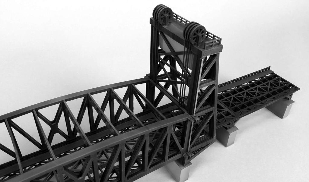
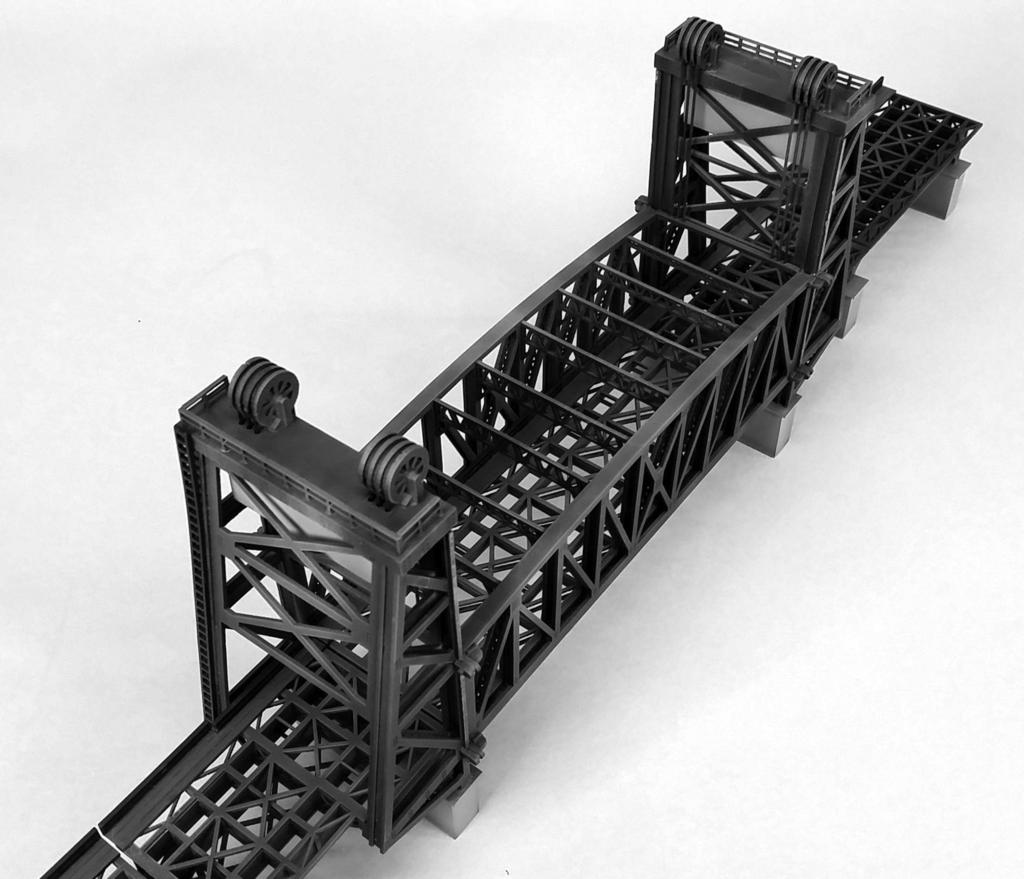
1 N Scale Double Track Lift Bridge v "W x 16"L x 7.5"H Plus two 5" long approach bridges Instructions for assembly of the Lift Bridge Included in this kit: Instructions and part diagrams 138ea. 1/16" laser cut loose parts 8ea. 1/16" laser cut parts sheets 4ea. 1/8" laser cut parts 1ea. 1/16" square rod 6ea.020" x 10" styrene round rod A vertical lift bridge has a span which rises vertically while remaining parallel with the track. The counterweights on a vertical lift bridge only have to be equal to the weight of the bridge, whereas on a bascule bridge counterweights must weigh several times more than the span being lifted. Therefore, heavier materials can be used on the deck of the lift bridge which makes it especially well suited for heavy railroad use. Our bridge is based upon typical lift bridges found in the United States spanning the Mississippi and other major rivers. These were built from the early 1900 s on. Our model has a 115 foot long lift span and towers that rise 75 feet. The entire bridge is raised on concrete piers and has unique footings. In addition to the lift bridge, the kit includes two 65 long girder bridges which may be used as approaches to the main bridge. This is a non operating model. Please read these instructions completely before beginning and take your time to become familiar with the parts. Allow parts to dry after painting or gluing and do not try to build this in one night. This is a big bridge and it will take a little time to build. Drawings of all the parts have been included for ease of part identification. In order to make the instructions and figures clear, some of the model assemblies have been painted gray prior to photographing. In some cases the model is gray and the newly added parts have been left white. This is only for illustration purposes. You should paint your model as indicated in the instructions. Practice gluing the acrylic together if you have never done it before. There is plenty of scrap in your kit that you can use for this. See Gluing Acrylic for more information on this. If by chance a part is missing or broken, please write us indicating the kit name and part number and we will send you a replacement. You will need the following items to assemble your model: hobby knife, paint, paint brushes, glue, modeling putty, tweezers, files and sanding block. 1
2 Gluing Acrylic Always glue acrylic in a well-ventilated area, and read the glue manufacturer s label for instructions. We recommend using Scalecoat Probond by Minuteman Scale Models or Plastruct brand Plastic Weld Solvent Cement or Bondine Solvent Cement. Most hobby shops carry these products or they may be ordered directly from o r Acrylic must be glued together using a solvent that will melt the two edges and literally fuse them together. To do this, place the two pieces to be joined together and run a bead of solvent down the edge. Capillary action will suck the solvent into the joint and after several seconds the pieces will be fused. After only a few minutes the pieces will be strong enough to work with. The bond will be completely dry within twenty four hours using the above-mentioned products. Solvent can be dispensed two ways. Typically the solvent comes in a small bottle with a brush in the lid. The brush allows you to dispense a drop or two of solvent at a time. You may want to use a polyethylene bottle or syringe with a blunt needle dispenser. This allows larger amounts of solvent to be dispensed quickly, accurately, and cleanly. Be sure the bottle you are using is approved for the solvent you are using or you may melt through it. These may be purchased from CMR. Preparing Your Model for Painting We recommend lightly sanding all parts to remove the raised edge created during the laser cutting process. In order to hide the seams we recommend using hobbyist putty such as Green Squadron modeling putty. Do this in a very well ventilated area. Apply the putty over the seams; allow to dry overnight. Once the putty has dried, place a sheet of fine sandpaper on a flat surface and sand smooth. You may need to apply a second coat of putty and sand again. Painting Your Model We primed our model with Krylon Gray Primer spray paint. We used Krylon Flat Black spray paint for the bridge. Krylon is available in most hardware stores. We also used hobby acrylics for details and weathering, these are available in most hobby shops. Always test compatibility of your paint with the acrylic by painting and testing a small area first. Using hobby acrylics paints, we painted flat black for touch up and weathering as well as the cables. The piers and counter weights were painted to look like concrete. The walkways and railings we painted brown. We airbrushed our model with rust and grime to make it look old and then sealed it with Krylon Matte Acrylic Spray. Never use alcohol or alcohol-based cleansers, paints or washes on acrylic. It will cause the acrylic to shatter and this is bad. 2

, (9), (10), (11) and (12) to the truss side (1). Use the engraved lines on part (1) for alignment. See figure 2.")
 and bottom (14) in place. See figure 3. Note that the two vertical end beams, parts (3), on the truss assembly are slightly taller than the rest.")
 so that it lays flat across the tops of the rest of the support beams.")
3 Bridge Truss Side Assembly There are two bridge truss assemblies; build one first and then the other. Lay the interior truss side (1) flat on your work space. This is the truss side with the slots cut into it. There are small engraved rectangles on one side of the part that should be facing up. Insert and glue two sets of the vertical support beams (3), (4), (5), (6) and (7) into the truss side (1). Use the tabs and slots to aid in position and alignment. See figure 1. Figure 1 Glue two sets of the webbed truss braces (8), (9), (10), (11) and (12) to the truss side (1). Use the engraved lines on part (1) for alignment. See figure 2. Glue the exterior truss side (2) to the assembly making sure that the side with the engraved rivets is facing up. See figure 3. Figure 2 Next glue the truss top (13) and bottom (14) in place. See figure 3. Note that the two vertical end beams, parts (3), on the truss assembly are slightly taller than the rest. The truss top (13) is shorter than the truss bottom (14). Glue the truss top between the end vertical support beams (3) so that it lays flat across the tops of the rest of the support beams. After assembly, it should sit between the truss sides so that it is flush with the top of the truss sides. Figure 3 Glue the truss top (13) and bottom (14) in place. See figure 3. Fill the seams along the top and bottom with green squadron modeling putty, allow to dry and sand or file flush. See figure 4. Now build the other truss assembly. Figure 4 3
 x 2 onto the beam support assembly. Make sure that the tabs on the cross braces (16) stick out beyond the top.")

 x 2 (this is located on the hoist platform parts sheet) to the inside top edge of brace (18) on each end of the bridge.")
4 Bridge Base Assembly Glue the cross braces (16) x 10 onto the beam supports (15) x 4 using the slots for alignment. Make sure the assembly is square. See figure 5. Glue the base top and bottom (17) x 2 onto the beam support assembly. Make sure that the tabs on the cross braces (16) stick out beyond the top. Test fit DO NOT GLUE the base assembly into the side truss assemblies in order to make sure that the tabs align with the slots. See figure 6. Figure 5 Bridge Assembly Glue the two side assemblies to the base assembly making sure that all the tabs are seated properly and that the assemblies are square to each other. Next glue two each of the top braces (18), (19), (20), (21), (22) between the side assemblies using the slots and tabs for alignment. Figure 6 Glue the cable plates (62) x 2 (this is located on the hoist platform parts sheet) to the inside top edge of brace (18) on each end of the bridge. See figure 7. Figure 7 Prime the bridge gray and paint it black. 4
 on your work table with the engraved side facing up.")
, (31), (32) and (33) into the slots on the cross braces of part (23).")
 into the slots on the face of part (24) (this is the side with only one set of slots). See figure 8. Repeat the process for the other side using parts (25) and (26).")
5 Tower Assembly The towers have side assemblies similar to the bridge except that they are not symmetrical. The sides will be built in mirrored facing pairs. As there are two towers you will need to build two pairs. Place the truss side part (23) on your work table with the engraved side facing up. Glue part (27) into the slots along the angled side of part (23). Glue part (28) into the slots along the straight side of part Figure 8 (23). Glue truss brace parts (30), (31), (32) and (33) into the slots on the cross braces of part (23). Glue webbed truss brace parts (34), (35), (36) and (37) onto part (23) using the engraved lines as guides. Glue part (24) on top of the assembly with the engraved rivets facing up. Glue the guide rail part (29) into the slots on the face of part (24) (this is the side with only one set of slots). See figure 8. Repeat the process for the other side using parts (25) and (26). This will make a mirrored assembly to the first one. See figure 9 Place the parts assembly (23), (24) so that the side with the slots is facing up. Glue part (38) into the slot at the top of the assembly. Glue part (39) onto the angled side of the side of the assembly, glue part (40) onto the straight side of the side assembly. Glue part (41) into the slot at the base of the assembly. See figure 10. Glue the parts assembly (25), (26) to the other side to form a square tower. Make sure the assembly is square. Figure 9 5 Figure 10
 and (43).")
 x 2 and (45) x 2 in alternating order. See figure 11.")
 to the underside of the bridge.")
 and (50) between two parts")

6 Attach the girders (42), (42A), (43A) and (43) to the bottom of the tower using the slots for alignment. Note the orientation of the engraved rivets on (42) and (43). They should be facing out. Insert the cross braces (44) x 2 and (45) x 2 in alternating order. See figure 11. Glue the top of the bridge webbing (46) to the girders. Flip the assembly over and glue the bottom webbing (47) to the underside of the bridge. See figure 12. Figure 11 Assemble the bridge foot by gluing parts (48) and (50) between two parts (49). See Figure 13. Glue the bridge foot to the end of the bridge tower base. See figure 14. Figure 15 shows the pair of towers completed. One has been primed while the other remains white. Prime gray and paint the towers black. Figure 12 Figure 13 Figure 15 Note: due to changes during the design process there are no parts (51) or (52). Figure 14 6
 will eventually be glued in place.")
 x 2 and (54) x 2 to the platform base (55) to form a box. The engraved side of part (55) should be facing up. Sand the parts after they have dried to remove any glue damage.")
. Use a piece of 1/16\" square styrene rod as a shaft.")
 x 4 into the base.")
7 Hoist Platforms There are two hoist platforms that are identical and sit on top of the towers. The platforms have large wheels which are used to hoist the bridge up and down. The wheels have notches in them where rod (representing the cables) will eventually be glued in place. On the front the rods will connect to the bridge, and on the back the rods will travel down through the floor to the counterweights. Glue the sides parts (53) x 2 and (54) x 2 to the platform base (55) to form a box. The engraved side of part (55) should be facing up. Sand the parts after they have dried to remove any glue damage. Install the railing (56) and (57) x 2 into the holes in the platform base. See figure 16. Figure 16 Assemble the hoist wheels using four parts (58) and three parts (59). Stack the parts in alternating order beginning and ending with part (58). Use a piece of 1/16" square styrene rod as a shaft. Make sure that all of the wheel parts (59) are aligned in the same manner (notches line up). Glue all the parts together. When dry, cut the square shaft so that it extends 1/32 beyond the wheels. You will need two of these for each tower. See figure 17. Glue the wheel braces (60) x 4 into the base. The side of the brace with the short bottom faces towards the front of the base (the side of the base without a railing). Glue the brace sides (61) x 4 to the outside of the braces flush with the base. Figure 17 Figure 18 Glue the wheels between the braces so that the notches are facing down. The square rod should snap into the holes in the wheel braces. Later we will install rods (cables) from below and fit them into the notches in the wheels. Repeat for the other platform. See Figure 18. Glue the platforms onto the top of the towers. The front of the hoist platform should face the straight side of the tower. See Figure 19. Figure 19 Prime gray and paint black. 7
 x 2 and the sides (63) x 2 to the bottom (64). Glue the top (65) onto the assembly. Fill the edges with modelers putty and sand smooth using a sanding block.")


8 Counterweights There are two counterweights to assemble. These are basically cubes. The top has holes that the cables will slide into. Glue the fronts (62) x 2 and the sides (63) x 2 to the bottom (64). Glue the top (65) onto the assembly. Fill the edges with modelers putty and sand smooth using a sanding block. There should be no visible seams when completed. See figure 20. Prime gray and paint concrete color. Figure 20 Bridge Piers There are two types of bridge piers. The large ones are for the front of the towers and the smaller ones are for the approach bridges. The parts are all tab and slot construction to help with alignment. The piers are basically cubes with a cap. You will need to build two of the large piers and four of the small piers. When finished fill all the seams with modeling putty and sand smooth prior to attaching the caps. Large Piers: Glue the fronts (66) x 2 and the sides (67) x 2 to the inside support parts (68) x 2 to form a cube. After filling and sanding glue the cap part (69) on top of the pier. See figure 21. Small Piers: Glue the fronts (70) x 2 and the sides (71) x 2 to the inside supports (72) x 2 to form a cube. After filling and sanding glue the cap part (73) on top of the pier. See figure 22. Figure 21 Prime gray and paint concrete color. Figure 22 8
 on the end, then a (75) and so on, alternating every other one. You should end with a brace (74) on each end. Make sure the assembly is square.")

9 Approach Bridges Glue the cross braces (74) x 6 and (75) x 5 onto the beams (76) x 2 using the slots for alignment. The rivets on the beams should be facing out. Begin with a brace (74) on the end, then a (75) and so on, alternating every other one. You should end with a brace (74) on each end. Make sure the assembly is square. Glue the top (77) and bottom (78) onto the beam assembly. Assemble the bridge feet by gluing parts (48) and (50) between parts (49) as done previously. Glue a foot onto either end of the bridge. See figure 23. Build two of the approach bridges. Prime gray and paint black. Figure 23 Bridge Guides There are eight bridge guides to assemble. These are guides that keep the bridge on guide rails mounted on the towers. Begin by gluing part (80) onto part (79). Next stack part (81), (82) and another (81) onto the pin on part (79) and glue in place. See figure 24 for location and orientation of the parts. Prime gray and paint black. Figure 24 9


10 Final Bridge Assembly At this point you should have all of the bridge components built. These include the lift bridge, two bridge towers, two approach bridges, two large piers, four small piers, two counterweights and eight bridge guides. We will begin by installing the counterweights in the bridge towers. You will be putting six rods through six holes at the same time so some patience will be required. Cut two of the.020" styrene rod into twelve equal pieces measuring 1 3/8". Insert the styrene rod into the holes in the tops of the counter weights and drop them all the way to the bottom. This should leave 11/16"" sticking up. Make sure that they are all parallel and square. Secure them in place with a drop of super glue. Double check they are still square and allow to dry. Once dry trim them flush if necessary and double check for burrs on the exposed ends of the rods. Paint the rods black. Weather the concrete counter weight at this point as they will soon become inaccessible. See figure 25. Slide the counterweight up into the bridge tower, run the six rods through the six holes in the hoist platform. The rods should fit into the notches in the hoist wheels. Glue in place with super glue while holding the weight so that the rods hang parallel to the flat side of the tower. You may need a second set of hands for this. Figure 25 Alternatively you may lay the tower on the straight side and insert the counterweight. You can add a shim or block under the weight so that the wires are parallel to the flat side. Then glue the rods in place to the hoist wheels. See Figure 26. Repeat for the other tower. Let dry completely. You may want to add some additional super glue to where the cables meet the wheels to ensure that the glue joint is strong. Figure 26 10


11 Next you will mount the bridge between the towers. Glue the 1/8" acrylic bridge mounts (83) x 4 between the flanges of the I beams on the ends of the bridge. The bridge mounts will stick out 1/16" of an inch from the flanges. See Figure 27. Next glue the towers to the bridge. The bridge mounts attached to and extending from the bridge will fit into the flanges on the towers. Assemble so that the floor of the bridge and the towers are perfectly flush and glue together. See Figure 28. Cut the remaining six pieces of styrene rod into Figure 27 twelve lengths of 3 1/4". Paint the rods black. The rods mount into the notches on the front of the hoist wheels and into the holes on the top of the bridge cable plate (62). You may want to test fit them and trim to fit. Glue in place with super glue. Install the bridge guides, there are two located on each side of the bridge top and bottom. Fit the guide over the guide rail (29) and glue in place. See Figure 28. Place the lift bridge on the piers. The two large piers go under the tower. Two of the small piers go under the ends of the tower bridges. These will be shared by the approach bridges. The remaining two small piers go under the ends of the approach bridges. Of course your arrangement can vary to suit your needs. Figure 28 11


12 Install bridge track (not included in this kit), we recommend using Micro Engineering bridge track. This is available from your local hobby shop or direct from Micro Engineering. Make sure it is centered on the bridge. You will need to super glue this to the bridge. You can use the walkways as a straight edge to push the track against in order to keep it straight. Paint the walkways and railings to resemble wood. Install the walk ways, as well as the railings along side of the track. The exact location of this will depend upon the width of the bridge track ties. Also install the ladders on the ends of the towers, they should be on the same side as the walkways. You can weather your bridge with drips and runs of brown and rust, as well as an airbrushed over spray of gray to resemble chalking paint. Install the bridge on your layout and enjoy. 12
13 13
14 Vertical Lift Bridge - Double Track - N Page 1 (13) x 2 (2) x 2 Not Actual Size (1) x 2 (14) x 2 (12) x 4 (4) x 4 (7) x 4 (8) x 4 (3) x 4 (6) x 4 (9) x 4 (11) x 4 (5) x 4 (10) x 4 Shown Actual Size
15 Vertical Lift Bridge - Double Track - N Page 2 (17) x 2 Not Actual Size (15) x 2 (16) x 10 (18) x 2 (19) x 2 (20) x 2 Shown Actual Size (21) x 2 (22) x 2 Lift Bridge Railing Not Actual Size Lift Bridge Walkway Ladder x 2
16 Vertical Lift Bridge - Double Track - N Page 3 (38) x 2 (27) x 2 (28) x 2 (29) x 2 (23) x 2 (40) x 2 Not Actual Size (24) x 2 (30) x 2 (31) x 2 (32) x 2 (33) x 2 Shown Actual Size (34) x 2 (35) x 2 (39) x 2 Not Actual Size (26) x 2 (25) x 2 (36) x 2 (37) x 2 (41)
17 Vertical Lift Bridge - Double Track - N Page 4 (64) BOTTOM (59) x6 (53) x2 (62) FRONT BACK (57) x2 (65) TOP (62) (62) (54) (54) (56) (55) SIDE (63) SIDE (63) (58) x8 (79) (81) (81) (82) (80) (60) (61) Shown Actual Size 2 sets
18 Vertical Lift Bridge - Double Track - N Page 5 (46) (50) (47) (44) (48) (45) (43) (43)A (42)A (49) (49) (42) Railing Walkway Shown Actual Size 2 sets
19 Vertical Lift Bridge - Double Track - N Page 6 (78) (76) (76A) (76A) (76) (77) Railing Walkway (75) (74) Shown Actual Size 2 sets
20 Vertical Lift Bridge - Double Track - N Page 7 (49) (48) (49) (50)
21 Vertical Lift Bridge - Double Track - N Page 8 (69) (69) (83) x 4 (66) (66) (66) (66) (68) (68) (67) (67) (67) (67) (68) (68) Not Actual Size Not Actual Size (71) (71) (71) (71) (72) (71) (71) (71) (71) (72) (73) (73) (72) (70) (72) (70) (72) (70) (70) (73) (73) (72) (70) (72) (72) (70) (70)
22
CONCEPT MODELS INSTRUCTIONS FOR PRODUCT: WABASH 1885 CABOOSE El Toro Way Stockton, CA 95210
 CONCEPT MODELS Web Address: http://www.con-sys.com Email: concept_models@con-sys.com 8810 El Toro Way Stockton, CA 95210 INSTRUCTIONS FOR PRODUCT: WABASH 1885 CABOOSE 2 CONCEPT MODELS WABASH 1885 CABOOSE
CONCEPT MODELS B737 FUSELAGE CARRIER COMPONENTS Sheep Ranch Rd. Mountain Ranch, CA Web Address:
 CONCEPT MODELS Web Address: http://www.con-sys.com 8331 Sheep Ranch Rd. Mountain Ranch, CA 95246 B737 FUSELAGE CARRIER COMPONENTS 2 CONCEPT MODELS PARTS BOEING 737 COMPONENTS Item PART NO. DESCRIPTION
How to make a parking lot base
 How to make a parking lot base I have had several requests for a how-to-do article on making bases and parking lots for the buildings, so here is how I made the base for the CVS Pharmacy. My model railroad
PATENTS ARE PENDING. Building Dimensions. Exterior Dimensions Roof Edge to Roof Edge
 Assembly Manual 8x9 PATENTS ARE PENDING Approximate Size 7640303 Storage Area Building Dimensions Exterior Dimensions Roof Edge to Roof Edge Interior Dimensions Wall to Wall Sq. Ft. Cu. Ft. Width Depth
Chapter 7. Roof Framing
 Chapter 7. Roof Framing 7.1 ROOFING PREP WORK 7.2 INSTALLING ROOF TRUSSES 7.3 INSTALLING PORCH TRUSSES 7.4 SHEATHING ROOF 7.5 INSTALLING SUB-FASCIA 7.6 BUILDING AND INSTALLING SCUTTLE BOX 7.7 INSTALLING
Agenda. Safety Decking Basics Decking Issues Felt Kick Out Flashing Fascia
 Decking & Fascia Agenda Safety Decking Basics Decking Issues Felt Kick Out Flashing Fascia 2 Chapter 7 Tools & Materials Tools for Decking Hammer Measuring Tape Chalk Line Speed Square Utility Knife Circular
SpaVault TM Installation Guide for Bullfrog Spas (7-10 x 7-10 x 38 )
") SpaVault TM Installation Guide for Bullfrog Spas (7-10 x 7-10 x 38 ) WARNING - When unpacking SpaVault, DO NOT discard styrofoam pieces, these are not packaging materials. Step 1 Excavation Important:
SpaVault TM Installation Guide for Bullfrog Spas (7-10 x 7-10 x 38 ) WARNING - When unpacking SpaVault, DO NOT discard styrofoam pieces, these are not packaging materials. Step 1 Excavation Important:
Building a 28mm German Machine Gun/Observation Bunker
 Building a 28mm German Machine Gun/Observation Bunker By Binhan Lin Introduction Principles of Design German design and placement of fortifications in WW2 was influenced by the emphasis on offensive operations.
A-Series Aluminum Gantry Crane
 SPANCO PRODUCT SPECIFICATIONS 1 A-Series Aluminum Gantry Crane This guide can be used to prepare a bid specification for the incorporation of an A-Series Gantry Crane into a competitive bid project or
Technical Service. INSTALLATION INSTRUCTIONS FOR TARAFLEX SPORT PRODUCTS over Gypsum base Products. This document refers to the following products:
 INSTALLATION INSTRUCTIONS FOR TARAFLEX SPORT PRODUCTS over Gypsum base Products This document refers to the following products: Product Width Width Ft. Installation direction Seams treatment Taraflex Surface
Modern Fire Station kit in HO scale
 Modern Fire Station kit in HO scale This kit includes all building parts milled in white styrene plastic, Plastruct brick sheet and clear window glazing. All parts fit together but may need light sanding
Container Installation Guide
 Continuous Insulation Container Installation Guide Panels and InSerts The InSoFast CX Container panel and the InSerts are designed to fit most shipping containers. Containers have three types of corrugations:
Container Installation Guide
 Container Insulation Container Installation Guide Panels and Inserts The InSoFast CX Container panel and the Inserts are designed to fit most shipping containers. Containers have three types of corrugations:
Industrial Shelving. Q Line, Z-Line/Steel Shelves, Bulk Storage and Heavy-Duty Reinforced Shelving SYSTEMS FOR SUCCESS
 Industrial Shelving Q Line, Z-Line/Steel Shelves, Bulk Storage and Heavy-Duty Reinforced Shelving Q Line & Z-Line/Steel Shelving Heavy Duty Reinforced Shelving & Bulk Storage Shelving 2 Industrial Shelving
Scratch-Building Concrete Bridge Piers Text and Photos by Steve Malcolm, Director, Eastern Iowa Division
 Scratch-Building Concrete Bridge Piers Text and Photos by Steve Malcolm, Director, Eastern Iowa Division Installing a model railroad bridge into a layout presents many unique challenges. One of the most
CEILING & WALL SYSTEMS
 CEILING & WALL SYSTEMS Axiom Perimeter Trim Commercial Ceilings and Walls Solutions Guide Axiom Perimeter Trim AXIOM Trim The Axiom family of products provide functional and visual options in ceiling design.
PILGRIM BSERVER SPACE STATION ASSEMBLY INSTRUCTIONS 1 MAIN THRUSTER BACK BONE-EXTENSION ROD NUCLEAR POWERED INTERPLANETARY SPACECRAFT.
 NUCLEAR POWERED INTERPLANETARY SPACECRAFT PILGRIM BSERVER SPACE STATION ASSEMBLY INSTRUCTIONS 1 MAIN THRUSTER a sub-assembly 2 3 b sub-assembly Glue engine bells (6 & 7) to pivot pins. 1 5 x6 6 4 x3 Assemble
Commercial Resilient Sheet Flooring
 Commercial Resilient Sheet Flooring INSTALLATION 160 South Industrial Blvd. Calhoun, GA. 30701 MohawkGroup.com Technical Services Department 508 East Morris St. Dalton, GA 30721 800.833.6954 product_tech@mohawkind.com
Optima Vector Plank. Installation Instructions. Ceiling
 Ceiling Systems Between us, ideas become reality Optima Vector Plank Installation Instructions 1. GENERAL 1.1. Product Description The Vector products referenced in these instructions are made from fiberglass.
SECTION SECTIONAL OVERHEAD DOORS
 SECTION 08360 SECTIONAL OVERHEAD DOORS PART 1 GENERAL 1.1 SECTION INCLUDES A. Aluminum Doors B. Track and Framing 1.2 RELATED SECTIONS A. Section 04810 - Unit Masonry Assemblies: Prepared opening in masonry.
OPTIMA Vector Plank Installation Instructions
 CEILING SYSTEMS Between us, ideas become reality OPTIMA Vector Plank Installation Instructions 1. GENERAL 1.1. Product Description The Vector products referenced in these instructions are made from fiberglass.
Pittsburgh Corning ProVantage Glass Block Installation System Assembly Instructions
 Pittsburgh Corning ProVantage Glass Block Installation System Assembly Instructions Introduction: The ProVantage Glass Block Installation System is the easiest way to install Pittsburgh Corning Premiere
Modern Manufactured Home kit in HO scale
 Modern Manufactured Home kit in HO scale This kit includes all building parts milled in white styrene plastic, laser cut acrylic, wood and clear window glazing. All parts fit together but may need light
E-Series Steel Gantry Crane
 SPANCO PRODUCT SPECIFICATIONS 1 E-Series Steel Gantry Crane This guide can be used to prepare a bid specification for the incorporation of an E-Series Gantry Crane into a competitive bid project or application.
Constructing Fixed Span Bridges From Floating Equipment
 Chapter 10. Constructing Fixed Span Bridges From Floating Equipment CONSTRUCTING FIXED SPANS FROM M4T6 EQUIPMENT Characteristics of M4T6 Fixed Spans Short freed spans erected with M4T6 components can provide
COMPOSITE (WPC) ENGINEERED VINYL FLOORING INSTALLATION
 ENGINEERED VINYL FLOORING INSTALLATION") COMPOSITE (WPC) ENGINEERED VINYL FLOORING INSTALLATION PLEASE READ ALL INSTRUCTIONS CAREFULLY BEFORE YOU BEGIN INSTALLATION! IMPROPER INSTALLATION WILL VOID WARRANTY. STOP! WPC Engineered Vinyl Flooring
COMPOSITE (WPC) ENGINEERED VINYL FLOORING INSTALLATION PLEASE READ ALL INSTRUCTIONS CAREFULLY BEFORE YOU BEGIN INSTALLATION! IMPROPER INSTALLATION WILL VOID WARRANTY. STOP! WPC Engineered Vinyl Flooring
Safety on Heights: Our Policy
 11/17/14 Safety on Heights: Our Policy Only volunteers over the age of 18 are allowed to work on heights of more than six feet off the ground. This includes all work on scaffolds. Only volunteers who are
Division 11 - Equipment Section 11401
 PART 1 - GENERAL 1.1 GENERAL A. Division 1 General Requirements applies and becomes a part of this Section of the Specification as fully as if repeated herein. B. Items of equipment which are included
ROOF MOUNT KIT OWNERS MANUAL
 ROOF MOUNT KIT OWNERS MANUAL Made in the USA by: Primus Wind Power, Inc. 938 Quail St. Lakewood, CO 80215 Phone: (303) 242-5820 www.primuswindpower.com AIR is a trademark of Primus Wind Power, Inc. ROOF
PV Mounting System 2703 SERIES 200 UL GROUND MOUNT SYSTEM. SnapNrack Residential PV Mounting Systems Code Compliant Installation Manual
 PV Mounting System 2703 SERIES 200 UL GROUND MOUNT SYSTEM SnapNrack Residential PV Mounting Systems Code Compliant Installation Manual Series 200 UL Introduction Series 200 UL Introduction SnapNrack Series
Making Your Own Interior Storm Windows
 Making Your Own Interior Storm Windows Windows are great for letting in sunlight during the winter to heat your home, but at night an under-insulated window will usually lose more heat than it lets in
INVITATION TO BID B I D F O R M. Please submit bid on or before 2:15 pm 101 North Halagueno Street June 6, 2013, at the office of the
 BID NO.: 2013-30 INVITATION TO BID B I D F O R M Refuse Containers, Roll-Out Refuse Containers, Lids, Lid Assemblies, Front & Rear Replacement Lids, Piano and Loop Hinges City of Carlsbad Please submit
Instructions for 12 IGT system
 Instructions for 12 IGT system Step 1: IGT Site Preparation Site Location Several factors must be considered when choosing the site for your new In-Ground Trampoline (IGT) system. Since local soil and
General Applications Before applying, mix the pre-measured catalyst* into Liquid Roof by following label directions.
 General Applications Before applying, mix the pre-measured catalyst* into Liquid Roof by following label directions. Surface Preparation: Surface to be coated should be clean, dry and structurally sound.
The Otji-Toilet self builder manual The Clay House Project Otjiwarongo
 - - The Otji-Toilet self builder manual The Clay House Project Otjiwarongo - 2 - The Otji-Toilet self builder set Your self builder set consists of following material 1 Lid box with following parts a)
How I Got My Golden Spike Award. Presented by Jeff Jarr
 How I Got My Golden Spike Award Presented by Jeff Jarr If you are new to the Achievement Program (AP), we recommend that you take a look at the Golden Spike Award. Although the Golden Spike Award is not
Basic Suspension Systems
 CEILING & WALL SYSTEMS Commercial Ceilings and Walls Solutions Guide Installing Armstrong Suspended Ceilings The ceiling system is made up of Armstrong panels which are supported by a suspension system
Steps in Building a Shed
 Steps in Building a Shed The design and location of your new shed will depend on how it will be used - a shed for storing tools will be much simpler than one you intend to use as a small shop. For example,
Revision 1 RAM ELEVATORS. Elevator Electrical Planning Guide. RAM Manufacturing Ltd
 RAM ELEVATORS Elevator Electrical Planning Guide This guide is intended for people with an understanding of electricity. If you are not, please consult a licensed electrician as errors in application of
T-Series Gantry Crane
 SPANCO PRODUCT SPECIFICATIONS 1 T-Series Gantry Crane This guide can be used to prepare a bid specification for the incorporation of a T-Series Gantry Crane into a competitive bid project or application.
HOW TO INSTALL PATIOS AND WALKWAYS STEP 2 STEP 1. For all Patios and Walkways. The base is the most important step in your patio and walkway projects.
 STEP 1 PREPARING YOUR PROJECT AREA Most commonly this is removing a grass area that is around your current concrete patio. You will incorporate this area into your new larger outdoor patio design. You
TITAN Quadcopter Assembly Instructions 1
 TITAN Quadcopter Assembly Instructions Even if you have built a multirotor before; please read these instructions carefully! There are a lot of tricks in here that can save you headaches in the future
SECTION RESILIENT SHEET FLOORING
 SECTION 09 65 16 RESILIENT SHEET FLOORING SPEC WRITER NOTE: Delete text between // // not applicable to project. Edit remaining text to suit project. PART 1 - GENERAL 1.1 SUMMARY A. Section Includes: 1.
Panel Installation Guide
 Panel Installation Guide Tool List: 1. Trowel A 1/32 or 1/16 inch square-notched trowel. You will be using this to spread out the glue. Remember to clean your trowel after each use. 2. Floor Roller This
Se incluyen las instrucciones en español
 Page 1 of 16 Pittsburgh Corning Corporation Pittsburgh, PA 15239 1-800-624-2120 www.pittsburghcorning.com All trademarks and registered trademarks in this brochure are owned and protected by Pittsburgh
Steel Door Frame Installation in Masonry Construction
 Steel Door Frame Installation in Masonry Construction Steel Door Frame Installation in Masonry Construction This manual provides step-by-step instructions for the installation of a steel door frame in
MODULAR ACOUSTIC FENCING INSTALLATION GUIDE
 MODULAR ACOUSTIC FENCING WWW.QUICKBUILTSYSTEMS.COM.AU INSTALLATION GUIDE INTRODUCTION THE QUICKBUILT FENCE SYSTEM IS A SMARTLY DESIGNED MODULAR SYSTEM EASY AND FAST TO INSTALL AND COST EFFECTIVE. // THE
ISO ven A Personal Size Family Wood Fired Oven Quick Installation Guide - Graphic
 ISO ven A Personal Size Family Wood Fired Oven Quick Installation Guide - Graphic A PRODUCT OF EARTHCORE INDUSTRIES, LLC. THIS Wood Fired Oven Is Designed for Outdoor Use Only with SOLID WOOD LOGS FOR
MDF WALL PANELS INSTALLATION INSTRUCTIONS
 MDF WALL PANELS INSTALLATION INSTRUCTIONS Please read these instructions carefully before installation to help you attain the desired results. These instructions are provided as guide as there are multiple
Proper Installation of Insulated Metal Wall Panels
 Proper Installation of Insulated Metal Wall Panels Insulated metal panels (IMPs) are an ideal cladding solution for pre-engineered metal buildings. They are available in lengths up to 50, and may also
TF-14. TF-14 Installation Guide
 TF-14 Trench Drain Forming System Installation Manual TF-14 Installation Guide P.O. Box 837 # 259 Murdock Road # Troutman, NC 28166 Tel (704) 528-9806 # Fax (704) 528-5478 Toll free in the U.S., Canada,
STEP UP SHOWER BASE INSTALLATION GUIDE FOR TIMBER AND CONCRETE FLOORS
 GUIDE FOR TIMBER AND CONCRETE FLOORS EDITION: APRIL 2016 IMPORTANT: This guide is for the installation of a Step Up shower base on a timber or concrete floor. If you require a walk in (flush with floor)
SECTION ROLLER GATES
 GENERAL SUMMARY A. The Contractor shall provide all labor, materials, equipment, and incidentals required to furnish and install roller gates, complete and operational with all necessary accessories as
The advantages of resistance welding versus Mig welding are: Weld consistency Weld strength Floor cleanliness.
 self-supported tri Flooring Systems Self-Supported TriDEK floors have a truss system that eliminates the need for floor frames or other support methods. TriDEK self-supported floors can be used to span
DO-IT-YOURSELF SELF ADHESIVE PLANK INSTALLATION
 Woodland Creek Series Self-Adhesive Residential Vinyl Plank Pattern Numbers: Sku 725-6664 PLK1102 Sable Sku 725-6666 PLK1106 Gray Wolf DO-IT-YOURSELF SELF ADHESIVE PLANK INSTALLATION MATERIALS YOU MAY
SECTION TURBINE VENTILATORS
 SECTION 07 72 00 TURBINE VENTILATORS **This is a CSI Three-Part Specification using CSI MasterFormat 2004-2010 Section Numbers and Titles. This specification must be edited to suit your particular project.
TUFF-TAC TM BRIDGE MEMBRANE INSTALLATION GUIDE
 5 pages TUFF-TAC TM BRIDGE MEMBRANE INSTALLATION GUIDE The following will describe the proper procedure to use when installing Tuff-Tac TM bridge deck membrane. The guide will cover recommended tools to
SECTION [ ] COILING COUNTER DOORS. Display hidden notes to specifier. (Don't know how? Click Here)
![SECTION [ ] COILING COUNTER DOORS. Display hidden notes to specifier. (Don't know how? Click Here)](/thumbs/77/75601156.jpg "SECTION [ ] COILING COUNTER DOORS. Display hidden notes to specifier. (Don't know how? Click Here)") SECTION 08332 [08 33 13] COILING COUNTER DOORS Display hidden notes to specifier. (Don't know how? Click Here) PART 1 GENERAL 1.1 SECTION INCLUDES A. Coiling Metal Counter Doors. B. Coiling Metal Counter
SECTION 08332 [08 33 13] COILING COUNTER DOORS Display hidden notes to specifier. (Don't know how? Click Here) PART 1 GENERAL 1.1 SECTION INCLUDES A. Coiling Metal Counter Doors. B. Coiling Metal Counter
SECTION WATERTIGHT GATES & BARRIERS FOR FLOOD & SPILL CONTROL
 HIGHLIGHTED AREAS TO BE INSERTED BY SPECIFYING ENGINEER SECTION 08316 - WATERTIGHT GATES & BARRIERS FOR FLOOD & SPILL CONTROL PART 1 GENERAL 1.1 WORK OF THIS SECTION A. THE WORK OF THIS SECTION INCLUDES
1.2 Reference Standard: NOFMA - National Oak Flooring Manufacturers Association Grading Standards.
 WOOD FLOORING GENERAL INFORMATION 1.1 This section applies to factory finished wood strip flooring. 1.2 Reference Standard: NOFMA - National Oak Flooring Manufacturers Association Grading Standards. 1.3
SECTION PLATE CONNECTED WOOD TRUSSES
 SECTION 06173 PLATE CONNECTED WOOD TRUSSES PART 1 GENERAL 1.01 SUMMARY A. Section Includes: 1. Shop fabricated wood trusses for roof and floor framing. 2. Bridging, bracing, and anchorage. B. Related Sections:
Dynamic Bonding Systems B.V. A division of Dutch Bonding Group B.V.
 for the bonding of facade cladding with KOMO-certified bonding system Dynamic Bond METALS - HPL - FIBRECEMENT Dynamic Bond For panels up to the maximum diagonal. Based on MS-hybrid-polymers, one component.
ITEM 458 WATERPROOFING FOR STRUCTURES
 ITEM 458 WATERPROOFING FOR STRUCTURES 458.1. Description. This Item shall govern for the furnishing and placing of waterproofing on concrete and steel bridge decks of railroad structures and on other structures
NORTH HARRIS COUNTY REGIONAL WATER AUTHORITY PIPE HANGERS, Section PIPE HANGERS, SUPPORTS, AND RESTRAINTS
 PART 1 GENERAL 1.01 SUMMARY Section 15140 PIPE HANGERS, This Section includes the furnishing and subsequent installation of: A. Pipe and equipment hangers, supports, and associated anchors B. Equipment
This guide can be used to prepare a specification for incorporating free standing jib cranes into a competitively bid construction project.
 SECTION 14651 FREE STANDING JIB CRANE ***** Gorbel, Inc. manufacturers a broad range of material handling cranes including monorail, bridge, gantry, and jib cranes. Numerous work station and industrial
Integrated Pest Management Program Department of Plant Science and Landscape Architecture UConn Extension
 Integrated Pest Management Program Department of Plant Science and Landscape Architecture UConn Extension Practical Ways to Increase Production Space One excellent way to reduce production cost per plant
SECTION COMPOSITE EXTERIOR SHUTTERS AND ACCESSORIES
 SECTION 10712 COMPOSITE EXTERIOR SHUTTERS AND ACCESSORIES PART 1 GENERAL 1.1 SECTION INCLUDES A. Functional exterior shutters. B. Exterior shutter hardware. 1.2 RELATED SECTIONS A. Section 09900 - Paints
Optima Vector Ultima Vector
 CEILING&WALL SYSTEMS Between us, ideas become reality Optima Ultima Installation Instructions ceiling panel items: OPTIMA: 3900, 3901, 3902, 3903, 3904, 3905, 3906, 3907, 3908, 3909 ULTIMA: 1920, 1921
Foundation Manual. Part Number: Version: Updated: July 5, S. Meadows Pkwy. A-9, #329 Reno, NV
 Foundation Manual Part Number: 150002 Version: 1.22 Updated: July 5, 2009 748 S. Meadows Pkwy. A-9, #329 Reno, NV 89521 775-831-9463 www.mariahpower.com July 2009, Mariah Power, All Rights Reserved Dear
Thin Brick Façade. Façades Installation Guide
 Thin Brick Façade Façades Installation Guide October 2016 BENCHMARK Welcome to Kingspan, global leaders in the design and manufacture of insulated metal panels. Insulated panels serve as energy efficient,
Carpet Tile & Plank Direct Glue Down
 Carpet Tile & Plank Direct Glue Down INSTALLATION EcoFlex ICT EcoFlex NXT EcoFlex AIR 160 South Industrial Blvd. Calhoun, GA. 30701 MohawkGroup.com Technical Services Department 508 East Morris St. Dalton,
THE WORLD LOOKS UP TO COMPOSITE ELEVATED TANK
 THE WORLD LOOKS UP TO COMPOSITE ELEVATED TANK or our breadth of capability. Of all the storage tank manufacturers doing business today, no other offers Caldwell s range of capability. We are the only manufacturer
TOP CAP Snaps into bottom track Aluminum - trimmed to length. RAMPS Covered by carpet ABS plastic and MDF QUESTIONS? CALL US AT !
 IN-CARPET WIREWAY INSTALLATION GUIDE 2.7 These components are typical for each wireway installation: WALL BASE TRIM Finishes cable opening at wall BOTTOM TRACK Screws to concrete Aluminum - trimmed to
Northpointe Renovation EPN #1701 F/A Project #17027 September 8, 2017
 SECTION 055213 - PIPE AND TUBE RAILINGS PART 1 - GENERAL 1.1 RELATED DOCUMENTS A. Drawings and general provisions of the Contract, including General and Supplementary Conditions and Division 01 Specification
Siding Installation Guide. v us
 Siding Installation Guide v20180201us IMPORTANT: Read All Sections Before You Start For the most up to date information, please visit our website @ www.newtechwood.com Prior to installing any composite
Tufted and Woven Goods Direct Glue-Down
 Tufted and Woven Goods Direct Glue-Down Installation Instructions Duraloc AIR Duraloc AIR Performance Unibond Flex Unibond Flex Bloc Unibond Laminate Unibond Plus Unibond Plus Bloc Weldlok Weldlok Bloc
SLAB ON GRADE Insul-Joint or Expansion Joint Material as Required by A/E Specifications AquaCheck Liquid Coating 400 (Waterproofing Membrane) with Aqu
 with Aqu") INSTALLATION INSTRUCTIONS Note: The following installation instructions are based off of ASTM E 1643 (Standard Practice for Installation of Water Vapor Retarders Used in Contact with Earth or Granular
INSTALLATION INSTRUCTIONS Note: The following installation instructions are based off of ASTM E 1643 (Standard Practice for Installation of Water Vapor Retarders Used in Contact with Earth or Granular
SYNTHETIC GRASS INSTALLATION GUIDE SOFT AND HARD SURFACE
 SYNTHETIC GRASS INSTALLATION GUIDE SOFT AND HARD SURFACE HARD SURFACE INSTALLATION You will need: Tape measure Rope or spray paint Weed spray Sharp utility knife and spare blades Synthetic grass adhesive
COLLEGE CLASSROOM & DORMITORY SPECIFICATION SECTION 08100
 COLLEGE CLASSROOM & DORMITORY SPECIFICATION SECTION 08100 Part 1 General 1.01 Work Included A. The work under this section shall include the furnishing of all items shown on the drawings and as specified,
FrameFast Shoring System
 FrameFast FrameFast Shoring System The FrameFast shoring system is engineered for maximum strength, labor productivity and reuse capabilities. FrameFast components feature high strengthto-weight ratios.
Windsor Fireplace Installation Instructions
 Windsor Fireplace Installation Instructions Thank you for your purchase of the Windsor Fireplace from Natural Concrete Products. Please familiarize yourself with these installation instructions before
SECTION SECTIONAL OVERHEAD DOORS 522 SERIES ALUMINUM SECTIONAL OVERHEAD DOORS. Display hidden notes to specifier. (Don't know how?
 SECTION 08360 SECTIONAL OVERHEAD DOORS 522 SERIES ALUMINUM SECTIONAL OVERHEAD DOORS Display hidden notes to specifier. (Don't know how? Click Here) PART 1 GENERAL 1.1 SECTION INCLUDES A. Glazed Aluminum
HOW TO INSTALL PATIOS AND WALKWAYS STEP 2 STEP 1. For all Patios and Walkways. The base is the most important step in your patio and walkway projects.
 New Project (replacing grass/dirt) STEP 1 PREPARING YOUR PROJECT AREA Determine how much to excavate using the example below. Remove the grass to desired depth (skim rather than dig deep) and a few inches
Single Post Anchor Part Number Spectrum Lane ~ Missoula MT ~
 Single Post Anchor Part Number 21700 7100 Spectrum Lane ~ Missoula MT 59808 800.791.8056 ~ www.spectrumproducts.com 21700 Man Rev B You have purchased a Spectrum Aquatics Single Post Anchor. Providing
Planning and installation instructions
 Planning and installation instructions Stofix Oy Ahlmaninkatu 2 E 40100 Jyväskylä Finland stofixgroup@stofix.com www.stofix.com 2 PLANNING AND INSTALLATION INSTRUCTIONS... 1 1 General... 3 2 Project Design...
PVC Project Assembly Guide a FORMUFIT field manual
 PVC Project Assembly Guide a FORMUFIT field manual www.formufit.com 1 PVC Project Assembly Guide 1 Welcome. This guide is designed to be friendly, knowledgable and to provide options for different people
OmniFlex 300 Plus Installation Instructions
 OmniFlex 300 Plus Installation Instructions IMPORTANT PortaFab advises a thorough reading of these instructions before beginning installation. INTRODUCTION Instructions should be read thoroughly and cross-referenced
1/17/2005 FAQ - Sothebys doc 1
 SOTHEBY S INTERNATIONAL REAL ESTATE FAQ TABLE OF CONTENTS SOTHEBY S INTERNATIONAL REAL ESTATE FAQ...1 TABLE OF CONTENTS...1 GENERAL FAQ...2 BUCKEYE UNIT 24 X 24...3 HOOSIER UNIT 24 X 24...5 PERSONALIZED
FPE-SERIES RETROFIT INSTALLATION INSTRUCTIONS
 FPE-SERIES RETROFIT INSTALLATION INSTRUCTIONS BRAVO FIBERGLASS RETROFIT-S SERIES FOR SINGLE WALL FRP SUMPS ONLY FOR RETROFITTING BOLTED FLEXIBLE ENTRY BOOTS POLYETHYLENE EXTERIOR PIPE ONLY BUILT LIKE A
AXIOM Indirect Light Coves
 AXIOM Indirect Light Coves Assembly and Installation Instructions 1. GENERAL 1.1 Description The Axiom Indirect Light Cove system is a pre-engineered lighting solution designed to be used at a ceiling-to-wall
A. Product Data: For each type of product, including panel products, high-pressure decorative laminate, adhesive for bonding plastic laminate.
 SECTION 123623 - PLASTIC-LAMINATE-CLAD COUNTERTOPS PART 1 - GENERAL 1.I RELATED DOCUMENTS A. Drawings and general provisions of the Contract, including General and Supplementary Conditions and Division
1. Vertical reciprocating conveyor, Hydraulic straddle VRC.
 PART 1: GENERAL 1.01 Section Includes: 1. Vertical reciprocating conveyor, Hydraulic straddle VRC. a. Machine, controller, platform, structural steel hoist frame. b. Wire mesh enclosure and gates. Related
Installation Instructions
 CELEBRATING 50YEARS HIGH PERFORMANCE COMPOSITE SOLUTIONS Installation Instructions Dynarail Safety Ladder System Building the World to Last Simplified Ladder Instructions The Dynarail Safety Ladder System
LATRINE CONSTRUCTION SHELTER. Pour flush latrine 2. Pour flush micro septic tank 3. Initial investment, location, human resources 4.
 LATRINE CONSTRUCTION Pour flush latrine 2 Pour flush micro septic tank 3 Initial investment, location, human resources 4 Concrete rings 5 Box 6 Cover 7 Slab and ceramic pan 8 Ring mold 9 Structure and
aquapanel InstallatIon GuIde
 Installation Guide AQUAPANEL BEFORE YOU START It s a good idea to stand the AQUAPANEL sheets in the area for 2 days prior to cutting and installing, to allow the sheets to breathe and reach moisture equilibrium.
Installation Instructions
 Installation Instructions Dynarail Safety Ladder System Corrosion Resistant Nonconductive Fire Retardant High Strength-To-Weight Ratio Long, Low Maintenance Life Meets OSHA, BOCA & Other Building Code
2017 VICTORIA BRANCH POPSICLE STICK BRIDGE BUILDING COMPETITION RULE BOOK
 2017 VICTORIA BRANCH POPSICLE STICK BRIDGE BUILDING COMPETITION RULE BOOK 1 of 8 Contents 1. Registration:... 3 2. Bridge Dimensions and Rules... 3 a) Construction... 3 b) Dimensions... 3 c) Materials
BioPrism Solid Surface
 Please read all instructions before installing products. STORAGE & HANDLING: Check for damage that may have occurred during transit. Keep receptor flat on pallet, as it was shipped, until ready to install.
ECONO 200 INPLANT OFFICE
 Warehouse Storage & Material Handling Equipment+ ECONO 200 INPLANT OFFICE INSTALLATION & ASSEMBLY INSTRUCTIONS American Surplus Inc. 1 Noyes Ave. East Providence, RI Phone: (800) 989-7176 Fax: (401) 434-7414
SECTION METAL FLOOR PLATE STAIRS
 SECTION 05513 - METAL FLOOR PLATE STAIRS PART 1 - GENERAL 1.1 RELATED DOCUMENTS A. Drawings and general provisions of the Contract, including General and Supplementary Conditions and Division 01 Specification