SEISMIC RESTRAINTS Multi-Directional Bracing For Electrical Conduit, Cable Tray And Mechanical Piping Systems
|
|
|
- Howard Shields
- 6 years ago
- Views:
Transcription


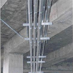
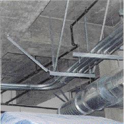
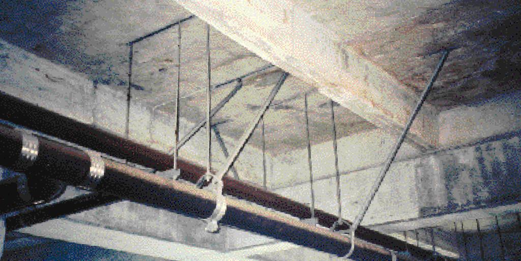


1 SEISMIC RESTRAINTS Multi-Directional Bracing For Electrical Conduit, Cable Tray And Mechanical Piping Systems SYSTEMS THAT MAKE SENSE
2 INTRODUCTION INTRODUCTION What is Seismic Bracing? Seismic forces are exerted on a building and its contents during an earthquake. These forces act horizontally upon the structure itself, as well as the piping, cable trays, ductwork, and other building systems within. Typical supports for piping, trays, and other equipment are designed for the gravity, or vertical, loads but do not take into account the horizontal loading caused by earthquakes. Seismic restraints (i.e. braces) resist the horizontal forces and keep the systems in place and secure. The main purpose seismic bracing is safety- to minimize the loss life due to an earthquake. Seismic Bracing Requirements The rules and requirements for the seismic restraints are published in the model building codes: The Uniform Building Code (Inter national Conference Building Officials), National Building Code (Building Officials and Code Administrators), Standard Building Code (Southern Building Code Congress International), and the International Building Code. Each code is similar in nature, and has a chapter on structural forces which defines the level seismic force that must be used in the design seismic restraints. The amount seismic force (as determined by the building code) is given as a percent the components weight, or g-force. If the horizontal force is determined to be 50 percent the piping weight, for example, the seismic force is.5g. The seismic "g-value" can vary greatly depending on the nature the project. Critical buildings in a high seismic zone have larger g-value requirements than warehouses in zone 1. Factors that govern the seismic g-values used for design: Seismic Zone Soil Type Building Type Distance from known faults Elevation within building Anchorage Type System being braced The design pressional should use these factors and the applicable building code requirements to determine the proper g-values to be used for the project. This manual has been developed under the requirements the 2001 California Building Code, and contains seismic bracing details that can be used for seismic bracing projects up to 1.0g (ASD) or 1.4g. The brace spacing charts, required details, and rod loads must be determined for the specific g-value for the project and shall be submitted to the engineer record prior to construction. The determination the seismic force level shall also be submitted to the engineer record and to OSHPD for hospital projects in the state California prior to construction. However, the seismic force level need not be submitted to the engineer record or OSHPD if included in the original construction documents. This brochure contains charts for a variety g values, however custom charts can be created to reflect different g-values as required for the project. Contact B-Line Engineering at with your requirements. A copy the complete Seismic Restraints Manual shall be on the jobsite for the duration the project. Appropriate shop drawings signed/stamped by the architect or engineer record must also be kept. OSHPD reserves the right to review these upon request. i
3 TABLE OF CONTENTS General Information & Notes Single Pipe/Conduit Bracing Selection Trapeze Bracing Selection Trapeze Members Structural Attachment Selection Concrete Wood Steel Hanger Rod Attachments & Approved Components Concrete Wood Steel Approved Components Rod Stiffeners Adjustable Hinge Hardware Pipe Hangers/Clamps Anchoring Components Metric Conversion Charts Seismic Map Appendix 1 Support Spacing Charts For Single Pipe/Conduit Applications (.15g,.30g,.45g,.50g,.75g and 1.00g) Appendix 2 Support Spacing Charts For Trapeze Applications (.15g,.30g,.45g,.50g,.75g and 1.00g) Appendix 3 Pro Test Instructions For Concrete Anchors (IR26-6) Appendix 4 Calculating Your Seismic Force Level Appendix 5 (Beyond the scope OSHPD) Additional Engineering Approvals ii
4 GENERAL INFORMATION B-LINE SEISMIC RESTRAINT SYSTEMS a re designed to resist seismic loading while minimizing installation time and providing superior perf o rmance. On the following pages, several methods seismic bracing are illustrated. The choice brace design should be governed by the system requirements and location supports. Actual applications may vary and are not strictly limited to the combinations fittings and supports shown. Any changes to the depicted designs should be in accordance with standard engineering practices and be approved by OSHPD (California Office Statewide Health Planning & Development) if necessary. For additional information on hangers, channels, fittings, and hardware shown, see the latest B-Line Strut Systems Catalog or Pipe Hangers and Supports Catalog. Seismic restraints are designed to resist the horizontal seismic force in two primary directions: Transverse (perpendicular) and Longitudinal (parallel) to the run. The braces are attached to the building with a structure attachment (for concrete, steel, wood, etc.) various anchor sizes. Typically, the stronger the structure attachment, the greater the brace spacing allowed. The following steps detail how to use the brochure: Step 1: Select the bracing details for single pipe hangers or trapeze supports. Step 2: Obtain required force level (%g) from applicable code for local jurisdiction or from the structural engineer record. Example: 2001 California Building Code As defined in the 2001 California Building Code, Chapter 16A, Section 1632A, the seismic horizontal force, F p, may be calculated using the following formula: F p = a pc a I p (1 + 3 hx )W p R p h r Where: Except that: F p shall not be less than 0.7 C a I p W p and need not be more than 4 C a I p W p. F p = Seismic Force Level a p = Amplification Factor (Table 16A-O) R p = Component Response Modification Factor (Table 16A-O) = 3.0 for electrical, mechanical and plumbing equipment and associated conduit, ductwork and piping utilizing deeply embedded anchors. (Table 16A-O) = 1.5 for installations using concrete anchors with an embedment-to-diameter ratio less than 8. i.e. a 1 /2" diameter concrete anchor with an embedment less than 4" inches. 1
5 GENERAL INFORMATION I p = Importance Factor (Table 16A-K) = 1.5 for Essential facilities such as Hospitals, Fire Stations, Police Stations, Aviation Control Towers, etc. consult Table 16A-K in CBC for a detailed listing. = 1.0 for most other occupancies C a = Seismic Coefficient. This is a cumulation several factors: Zone, Soil Properties, and distance from known fault. (Table 16A-I, Table 16A-J, Table 16A-Q, Table 16A-S, and Table 16A-U) h x = Element or component attachment elevation with respect to grade. Note: h x shall not be taken less than 0.0 h r = Structure Ro Elevation with respect to grade. Special Note: This manual is based on allowable stress design (ASD), where as the seismic force level (%g or F p ) for non-structural components provided in building codes are based on strength design. For use in this manual, the seismic force levels (F p ) from the building code are converted to allowable stress design by dividing the result by 1.4. Example: If the building code yields, (F p ) = 1.4g, this value is converted to allowable stress design (ASD) as used in this catalog as follows: F p =1.4g/1.4=1.0 g Strength Design to Allowable Stress Design Conversions.21g from building code =.15g (ASD).42g from building code =.30g (ASD).63g from building code =.45g (ASD).70g from building code =.50g (ASD) 1.05g from building code =.75g (ASD) 1.40g from building code = 1.00g (ASD) Example One, Deeply Embedded Anchors: Cable tray system is installed on the 1st floor a 40-foot tall, 2-story surgical center in California. The cable tray is actually suspended from the bottom the 2nd floor, which has an elevation 20 feet above grade. Location the surgical center is in seismic zone 4 with a rock soil prile. F p = a pc a I p (1 + 3 hx )W p R p h r a p = 1.0 from Table 16A-O 2
6 GENERAL INFORMATION C a =.40Na from Table 16A-Q, which is a combination Zone and Soil prile Zone 4 =.40, from Table 16A-I Rock Soil Prile = SB, from Table 16A-J Seismic Source Type = B, for faults other than Type A & C (Table 16A-U) Near Source Factor (Na) = 1.0, for 5 km from known seismic source (Table 16A-S) I p = 1.5 from Table 16A-K, Occupancies having surgery and emergency treatment areas. R p = 3.0 from Table 16A-O for deep embedded anchors h x = 20 feet h r = 40 feet F p = (1.0)(0.40(1.0))(1.5) ( )W p = 0.50W p = 0.50g Check if value falls within limits: F p shall not be taken less than, 0.7C a I p W p = 0.7(.40)(1.5)W p =.42g F p shall not be greater than, 4.0C a I p W p = 4.0(.40)(1.5)W p = 2.4g 2.4g >.5 > 0.42g Therefore allowing the use 0.50g To convert this F p from a strength design to an Allowable Stress Design (ASD) used in this catalog divide by 1.4. F p = 0.50g = 0.36g (ASD) g is the Allowable Stress Design Seismic Load Factor determined from the 2001 California Building Code. Special Note: A table for.36g (ASD) is not available in this catalog. When seismic force levels (%g or F p ) falls between catalog table values (i.e.:.15g,.30g,.45g, etc.) the seismic force level shall be rounded up to the next highest cataloged force level. Example: If F p =.36g (ASD), then use catalog tables for.45g (ASD). Example Two, Shallow Embedded Anchors: Special Note: Installations using concrete anchors installed with an embedment length-to-diameter ratio less than 8, also referred to as shallow embedment anchors, have an adjusted Component Response Factor. The adjusted factor R p =
7 GENERAL INFORMATION Cable tray system is installed on the 1st floor a 40-foot tall, 2-story surgical center in California. The cable tray is actually suspended from the 2nd floor, which has an elevation 20 feet above grade. Location the surgical center is in seismic zone 4 with a rock soil prile, shallow embedment anchors are used for brace locations. a p = 1.0 from Table 16A-O F p = a pc a I p (1 + 3 hx )W p R p h r C a =.40Na from Table 16A-Q, which is a combination Zone and Soil prile Zone 4 =.40 from Table 16A-I Rock Soil Prile = SB from Table 16A-J Seismic Source Type = B for faults other than Type A & C (Table 16A-U) Near Source Factor (Na) = 1.0 for 5 km from known seismic source (Table 16A-S) I p = 1.5 from Table 16A-K, Occupancies having surgery and emergency treatment areas. R p = 1.5 adjusted for Shallow Embedment Anchors h x h r = 20 feet = 40 feet F p = (1.0)(0.40(1.0))(1.5) ( )W p = 1.0W p = 1.0g Check if value falls within limits: F p shall not be taken less than, 0.7C a I p W p = 0.7(.40)(1.5)W p =.42g F p shall not be greater than, 4.0C a I p W p = 4.0(.40)(1.5)W p = 2.4g 2.4g > 1.0g > 0.42g Therefore allowing the use 1.0g To convert this F p from a strength design to an Allowable Stress Design (ASD) used in this catalog divide by 1.4. F p = 1.0g = 0.71g (ASD) g is the Allowable Stress Design Seismic Load Factor determined from the 2001 California Building Code for shallow embedment anchors. Special Note: A table for.71g (ASD) is not available in this catalog. When seismic force levels (%g or F p ) falls between catalog table values (i.e.:.15g,.30g,.45g, etc.) the seismic force level shall be rounded up to the next highest cataloged force level. Example: If F p =.71g (ASD), then use catalog tables for.75g (ASD). Note: For other Code examples see Appendix 4 4
8 GENERAL INFORMATION Step 3: With required force level (%g), obtain the transverse and longitudinal brace spacing from Appendix 1 (single pipe) or Appendix 2 (trapeze hanger). The following notes shall be followed: a) B reak the length pipe into separate straight runs, which are considered to be a single straight section between any bends in the pipe except where the bend is at an fset less than the maximum fset length as defined below. Table 1 - Steel Pipe or Conduit Nominal Max. Offset Length (ft) Pipe Size 0.15g 0.3g 0.5g 0.75g 1.0g Table 2 - Copper Tubing Nominal Max. Offset Length (ft) Tubing Size 0.15g 0.3g 0.5g 0.75g 1.0g Note: The tabulated values represent pipe and tubing with moment and shear transfering joints. T h e re f o re, for use these tables pipes shall have welded, brazed, or UL Listed grooved joints. Pipe and tube sizes not listed above or joined as re q i u i red shall be limited to a maximum fset length 2 ft. Maximum Offset Length (ft.) b) Brace each straight run in the transverse direction at both ends. Where several short runs occur, see note e) on the following page. Straight Run Transverse bracing at both ends the pipe run 5
9 GENERAL INFORMATION c) Check the required spacing for transverse bracing (Appendixes 1 & 2) and compare it to the length the straight run. If the length the straight run is greater than the allowable distance for transverse bracing add transverse braces until the spacing does not exceed the allowable transverse brace distance. Straight Run Additional s d) Each straight run must have at least one longitudinal brace. Add longitudinal braces so that the spacing does not exceed the allowable longitudinal brace spacing in Appendixes 1 & 2. Straight Run Longitudinal Brace (Transverse brace for the adjacent run) Longitudinal Brace Longitudinal Brace (Transverse brace for the adjacent run) 24 (610mm) Max. 24 (610mm) Max. Note: A transverse brace may dually act as a longitudinal brace for an adjacent run when it is located within 24 the adjacent straight run. However, Appendixes 1 & 2 shall be reviewed to use the stronger the longitudinal or transverse brace re q u i rements, i.e. anchor and other component sizes. 6
10 GENERAL INFORMATION e) In many cases, several short runs occur one after the other. Based on previous requirements, each straight run requires a longitudinal brace when the adjacent short runs exceed the maximum fset length (ft.). When the adjacent short runs do not exceed the maximum fset length (ft.) the longitudinal braces can act as transverse braces as long as the allowable transverse brace spacing (Appendixes 1 & 2) is not exceeded. In the following layout, transverse braces are used as longitudinal braces when the straight runs are less than the maximum fset length (ft.). When a straight run exceeds the maximum fset length (ft.) additional braces are required. First Second Longitudinal brace Two braces may be required. Straight run exceeding the maximum fset length (ft.) Longitudinal brace Short run less than the maximum fset length (ft.) Multiple fsets can be treated as a single run when the total fset is less than the maximum fset length (ft.). Plan or Elevation 7
11 GENERAL INFORMATION f) When a flexible connection or swing joint is used, such as at a pipe drop to mechanical equipment, the pipe may cantilever at a length equal to or less than half the allowable transverse brace spacing (Appendixes 1 & 2). When greater than half the allowable transverse brace spacing, support to the floor is required as shown below. Straight Run Transverse brace at the end horizontal run Requires a flexible connection or swing joint between equipment. Allowable Spacing 2 Mechanical equipment. Floor If < 6 ft. Support to Floor Is Required. Step 4: Note the structure connection type (brace anchor requirements) from the Appendix, and select the brace anchorage detail to suit (pages 23 thru 38). Step 5: Note the hanger rod load from the Appendix, and select a rod attachment to structure to suit (pages 39 thru 56). Step 6: Check if rod stiffeners are required (pages 57 & 58) to prevent the hanger rod from buckling. Seismic restraints may typically be o m i t t e d for the following conditions where flexible connectors are provided between components and the associated ductwork, piping, and conduit: 1. Fuel, medical gas, and vacuum piping less than 1 inch (25 mm) inside diameter. 2. All other piping less than 2 1 /2 inches (64 mm) diameter, or: All piping suspended by individual hangers 12 inches (305 mm) or less in length from the top the pipe to the bottom the structural support for the hanger All electrical conduit less than 2 1 /2 inches (64 mm) trade size 3. All rectangular air-handling ducts less than 6 ft 2 (0.56 m 2 ) in cross sectional area or: All round air-handling ducts less than 28 inches (711 mm) in diameter All ducts suspended by hangers 12 inches (305 mm) or less from the top the duct to the bottom the structural support for the hanger; where the hangers are detailed to avoid bending the hangers and their connections. (To eliminate bending moment, flexible connections may be used. See B752 on page 49 or B446 & B446C on page 56) Where lateral restraints are omitted, the piping, ducts, or conduit shall be installed such that lateral motion the piping, duct, or conduit will not cause damaging impact with other systems or structural members, or loss vertical support. NOTE: Reference building code enforced by local authority with jurisdiction for specific requirements, and verify all omissions or exemptions with structural engineer record. 8
12 GENERAL NOTES FOR SEISMIC BRACING GENERAL NOTES FOR SEISMIC BRACING A) The seismic restraint assemblies shown in this pre-approval document are designed to resist vertical loading simultaneously with seismic loading (transverse & longitudinal loading). Design recommendations shown are for single standard weight steel pipes filled with water. Contents other than water shall be evaluated by the user. Pipes other approved materials shall be supported in accordance with their approved installation standards. Details not shown in this pre-approval shall be submitted to OSHPD for approval before installation if necessary. B) This bracing system is limited to the pipe sizes and support details shown. Special consideration must be given for pipe material and connections, insulation, thermal movement, vibration, and building seismic joints. C) Transverse and longitudinal braces shall be no more than 45 above or below the centerline the pipe, duct, or tray. D) All channel and pipe clamp nuts and bolts shall be tightened to the following torques: 1/4"-20 to 6 ft.-lbs. (8 N m) 3/8"-16 to 19 ft.-lbs. (26 N m) 1/2"-13 to 50 ft.-lbs. (68 N m) 5/8"-11 to 65 ft.-lbs. (88 N m) 3/4"-10 to 75 ft.-lbs. (101 N m) E) The transverse and longitudinal bracing spacing listed in Appendix 1 & 2 is based on ductile piping (steel, copper, etc.) with ductile connections (welded, brazed, etc.) and has the following limitations: 1) Transverse bracing shall not exceed 40-0 (12.2 m). Longitudinal bracing shall not exceed 80-0 (24.4 m). 2) Fuel piping shall have transverse bracing 20'-0" (6.1 m) o.c. maximum and longitudinal bracing 40'-0" (12.2 m) o.c. maximum. 3) Non-ductile piping, and piping with non-ductile connections shall have transverse bracing 20'-0" (6.1 m) o.c. maximum and longitudinal bracing 40'-0" (12.2 m) o.c. maximum or 1 /2 the calculated brace spacing indicated in Appendix 1 or 2, whichever is more restrictive. F) Transverse bracing for one pipe section may also act as longitudinal bracing for the pipe section connected to it, if the bracing is installed within 24 inches (609 mm) the elbow or tee similar size. Figures 2 and 4 do not serve as adequate longitudinal braces. 9
13 GENERAL NOTES FOR SEISMIC BRACING G) Branch lines a smaller diameter shall not be used to brace main lines. H) Where rod stiffeners are required a minimum two hanger rod stiffener assemblies shall be installed. (Part number SC-228 or SC-UB) I) It is important to check anchorage details against the applicable building code requirements. Seismic design forces may increase substantially when anchors are considered shallow (embedded less than 8 times the anchor diameter). J) When bracing trapeze type hangers, the bracing shall be attached directly to the trapeze hanger assembly and piping secured to the trapeze assembly with pipe straps. K) A rigid piping system shall not be braced to diff e rent parts a building that may re s p o n d differently during an earthquake. Example: Solid concrete wall and a ro (metal deck filled with lightweight concrete). Special care should be taken to avoid bracing rigid pipe on both sides a building seismic joint without allowing for pipe and building movement. L) The pre-approval document is based on British Units (Inches & Pounds) and values noted in parenthesis (Metric or S.I. Units) are equivalent values. In case conflicts, British Units will be the standards for evaluating the proper application pre-approvals. M) The designer the structure shall determine the adequacy the support structure to carry the load the piping and equipment. Engineer record for a site specific project shall verify that the structure can support the connection loads the hanger rod and the bracing attachments in addition to all other loads. This pre-approval document is not intended for the seismic design the piping itself. The dynamic properties the building structure and piping should be considered when selecting the type piping to be installed. N) Seismic bracing shall not limit the expansion and contraction the piping system. Always consider thermal movements when selecting brace locations and materials. The design for thermal movements is beyond the scope OSHPD pre-approval. P) No portion this pre-approval shall be taken out context and used in other systems, design or purpose. Q) On transverse bracing, the pipe insulation material may be part the brace assembly (i.e) in the load path. In this case the insulating material shall be capable withstanding the lateral forces without damage and shall include a pipe shield for hangers or a pipe saddle for rollers. For longitudinal bracing, clamping must be applied directly to the pipe with any insulation being installed directly over the hanger and brace assembly. In these applications the mechanical engineer record shall be contacted for insulating recommendations. 10
14 B-LINE CHANNEL BRACES The following B-Line channels may be used as brace members for Figures 1-11 using the following structure connection types: Maximum Maximum Channel Channel Material Channel Structure Brace Height Width Thickness Type* Connection Length Type** (m) (mm) (mm) (mm) B54 IV 4-10 (1.47) 13/16 (20.6) 1 5 /8 (41.3) 14 Ga. (1.9) B52 IV 4-8 (1.42) 13/16 (20.6) 1 5 /8 (41.3) 12 Ga. (2.6) B42 V 5-10 (1.78) 1 (25.4) 1 5 /8 (41.3) 12 Ga. (2.6) B32 V 8-0 (2.44) 1 3 /8 (34.9) 1 5 /8 (41.3) 12 Ga. (2.6) B24 IV 9-7 (2.92) 1 5 /8 (41.3) 1 5 /8 (41.3) 14 Ga. (1.9) B22 V 9-5 (2.74) 1 5 /8 (41.3) 1 5 /8 (41.3) 12 Ga. (2.6) B22A V (3.30) 3 1 /4 (82.5) 1 5 /8 (41.3) 12 Ga. (2.6) B11 IV 11-7 (3.53) 3 1 /4 ( 82.5) 1 5 /8 (41.3) 12 Ga. (2.6) *Slotted channel (SH) versions all the above types may also be used for brace members. See page 21 for channel details. **The Structure Connection Type is the brace anchorage requirement. See pages for brace attachment details. Note: Do not exceed the maximum brace length or maximum structure connection type for the channels listed. Commentary: Appendix 1 & 2 list the allowable structure connection type (I, II, III, IV, or V) for each brace spacing listed. The structure connection type limits the amount axial load (in tension or compression) which is applied to the brace member. The axial load is listed for each structure connection detail on pages 23-38, and is as follows: Structure Connection Type Maximum Axial Load in Brace Member I lbs. (0.78 kn) II lbs. (1.33 kn) III lbs. (2.00 kn) IV lbs. (3.00 kn) V lbs. (4.33 kn) The B-Line channel brace member must have a capacity greater than the value listed in the above table for the maximum recommended brace length. 11
15 SINGLE PIPE/CONDUIT BRACING Single Rod Hanger Pipe Bracing 1) Layout piping run and determine size and location piping. 2) Select vertical supports (single rod pipe hangers). a) Select type hanger dependent on type pipe, thermal expansion and contraction, etc. b) Determine maximum spacing hanger rods and minimum hanger rod diameter. (Appendix 1) c) Select hanger rod connection to the structure based on structure type, rod size and hanger rod load from Appendix 1. Refer to section on hanger rod attachment for details (pages 39 thru 56) d) Engineer record for a site specific project shall verify that the structure can support the connection loads in addition to all other loads. 3) Select lateral bracing (transverse and longitudinal bracing). a) Select bracing details (transverse & longitudinal) from Figures 1 thru 8. b) Determine maximum spacing for transverse and longitudinal braces. (Appendix 1) c) Determine the type structure connection required. (Appendix 1) Refer to section on structural attachments for connection details. d) Determine if rod stiffener is required. (pages 57 & 58) e) Engineer record for a site specific project shall verify that the structure can support the connection loads. 4) Review the design and revise layout where loads exceed the limitations the hanger ro d s, hangers or connection details. 12
16 SINGLE PIPE BRACING CLEVIS HANGER TRANSVERSE BRACING (Figure 1) ATR All Threaded Rod (See Page 57 for minimum diameter) Rod Stiffener (See Pages 57 & 58) 1 1 (Min.) B335-2-Bolt Size Adjustable Hinge B3100PS Pipe Sleeve B3100 Series Clevis Hanger (See Page 63) Adjustable Pipe Pipe Size Clevis Hanger Hinge Sleeve in. (mm) Part No. Part No. Part No.* 1/2" (15) B /2 N/A N/A 3/4" (20) B /4 N/A N/A 1" (25) B B /8 B3100PS /4" (32) B /4 B /8 B3100PS-1 1 /4 1 1 /2" (40) B /2 B /8 B3100PS-1 1 /2 2" (50) B B /8 B3100PS /2" (65) B /2 B /8 B3100PS-2 1 /2 3" (80) B B /8 B3100PS /2" (90) B /2 B /8 B3100PS-3 1 /2 4" (100) B B /8 B3100PS-4 5" (125) B B /2 B3100PS-5 6" (150) B B /2 B3100PS-6 8" (200) B B /8 B3100PS-8 10" (250) B B /4 B3100PS-10 12" (300) B B /4 B3100PS-12 * Not included when ordering standard B3100 Series Clevis Hanger. Notes: Pipe sleeve required over cross bolt Clevis Hanger when using the brace connection shown above (Figure 1). Pipe sleeve is not required when clevis hanger is used in conjunction with the bracing shown in Figure 6 - page 15. Refer to Note Q) on page 10 for installations requiring insulated pipe. "J" HANGER TRANSVERSE BRACING (Figure 2) Rod Stiffener May Be Required (See Pages 57 & 58) ATR All Threaded Rod (See Page 57 for minimum diameter) 1 1 Min. B335-2-Bolt Size Adjustable Hinge B3690 Series 'J' Hanger (See Page 64) Adjustable Pipe Size "J" Hanger Hinge in. (mm) Part No. Part No. 1/2" (15) B /2 N/A 3/4" (20) B /4 N/A 1" (25) B B /8 1 1 /4" (32) B /4 B /8 1 1 /2" (40) B /2 B /8 2" (50) B B /8 2 1 /2" (65) B /2 B /2 3" (80) B B /2 3 1 /2" (90) B /2 B /2 4" (100) B B /2 5" (125) B B /2 6" (150) B B /2 8" (200) B B /2 Note: Refer to Note Q) on page 10 for installations requiring insulated pipe. 13
17 SINGLE PIPE BRACING PIPE CLAMP TRANSVERSE BRACING (Figure 3) ATR All Threaded Rod (See Page 57) Rod Stiffener May Be Required (See Pages 57 & 58) 1 (Min.) Adjustable Pipe Size Pipe Clamp * Hinge in. (mm) Part No. Part No. 1 B3200 Series Weldless Eye Nut 1 1 /2" (40) B /2 B /2 2" (50) B B /2 2 1 /2" (65) B /2 B /2 3" (80) B B /2 4" (100) B B /8 B335-2-Bolt Size Adjustable Hinge 5" (125) B B /8 6" (150) B B /4 8" (200) B B /4 10" (250) B B /4 12" (300) B B /4 B3144 Series Double Bolt Pipe Clamp (See Page 65) * See note D) on page 9 for clamp torque values. Note: Refer to Note Q) on page 10 for installations requiring insulated pipe. PIPE ROLLER TRANSVERSE BRACING (Figure 4) ATR All Threaded Rod (See Page 57 for minimum diameter) Rod Stiffener (See Pages 57 & 58) Adjustable Pipe Size Pipe Roller Hinge in. (mm) Part No. Part No. 1 1 (Min.) 2 1 /2" (65) B /2 B /2 3" (80) B B /2 3 1 /2" (90) B /2 B /2 4" (100) B B /2 5" (125) B B /8 6" (150) B B /4 B335-2-Bolt Size Adjustable Hinge B3110 Series Adjustable Steel Yoke Pipe Roll (See Page 66) Note: Refer to Note Q) on page 10 for installations requiring insulated pipe. 14
18 SINGLE PIPE BRACING TRANSVERSE BRACING (Figure 5) B2400 Series Pipe Strap (See Page 71) 1 1 (Min.) 3 min. (76mm) Channel Nuts & Bolts Not Included (See Pages 61 & 62) Notes: Install brace within 4" (101mm) hanger. (Hanger not shown for clarity. See Figure 6 below) Refer to Note Q) on page 10 for installations requiring insulated pipe LONGITUDINAL BRACING (Figure 6) Rod Stiffener May Be Required (See Pages 63 & 64) B335V-Bolt Size Adjustable Half Hinge Pipe Adjustable Riser Adjustable Pipe Size Clamp* Half Hinge Clamp * Half Hinge in. (mm) Part No. Part No. Part No. Part No. Pipe Hanger or Support 4 max. (101mm) Longitudinal Brace B3140 Pipe Clamp or B3373 Riser Clamp Series (See Pages 67 & 69) 1" (25) B B335V- 1 /2 B B335V- 1 /2 1 1 /4" (32) B /4 B335V- 1 /2 B /4 B335V- 1 /2 1 1 /2" (40) B /2 B335V- 1 /2 B /2 B335V- 1 /2 2" (50) B B335V- 1 /2 B B335V- 1 /2 2 1 /2" (65) B /2 B335V- 1 /2 B /2 B335V- 1 /2 3" (80) B B335V- 1 /2 B B335V- 1 /2 3 1 /2" (90) B /2 B335V- 1 /2 B /2 B335V- 1 /2 4" (100) B B335V- 5 /8 B B335V- 1 /2 5" (125) B B335V- 5 /8 B B335V- 1 /2 6" (150) B B335V- 3 /4 B B335V- 1 /2 8" (200) B B335V- 3 /4 B B335V- 5 /8 10" (250) B B335V- 5 /8 12" (300) B B335V- 5 /8 * See note D) on page 9 for clamp torque values. Notes: Install brace within 4" (101mm) hanger. Refer to Note Q) on page 10 for installations requiring insulated pipe. 15
19 CLEVIS HANGER TRANSVERSE BRACING (Figure 7) SINGLE PIPE BRACING - COPPER TUBING ATR All Threaded Rod (See Page 57 for minimum diameter) Rod Stiffener (See Pages 57 & 58) 1 1 (Min.) B335-2-Bolt Size Adjustable Hinge B3104CTPS Pipe Sleeve B3104CT Series Clevis Hanger (See Page 68) Copper Adjustable Pipe Tubing Size Clevis Hanger Hinge Sleeve in. (mm) Part No. Part No. Part No.* 1/2" (15) B3104CT- 1 /2 N/A N/A 3/4" (20) B3104CT- 3 /4 N/A N/A 1" (25) B3104CT-1 B /8 B3104CTPS /4" (32) B3104CT-1 1 /4 B /8 B3104CTPS-1 1 /4 1 1 /2" (40) B3104CT-1 1 /2 B /8 B3104CTPS-1 1 /2 2" (50) B3104CT-2 B /8 B3104CTPS /2" (65) B3104CT-2 1 /2 B /8 B3104CTPS-2 1 /2 3" (80) B3104CT-3 B /8 B3104CTPS /2" (90) B3104CT-3 1 /2 B /8 B3104CTPS-3 1 /2 4" (100) B3104CT-4 B /8 B3104CTPS-4 * Not included when ordering standard B3104CT Series Clevis Hanger. Notes: Pipe sleeve required over cross bolt Clevis Hanger when using the brace connection shown above (Figure 7). Refer to Note Q) on page 10 for installations requiring insulated pipe. LONGITUDINAL BRACING (Figure 8) Rod Stiffener May Be Required (See Pages 57 & 58) B335V-Bolt Size Adjustable Half Hinge Copper Riser Adjustable Tubing Size Clamp * Half Hinge in. (mm) Part No. Part No. Longitudinal Brace 1" (25) B3373CT-1 B335V- 1 /2 1 1 /4" (32) B3373CT-1 1 /4 B335V- 1 /2 1 1 /2" (40) B3373CT-1 1 /2 B335V- 1 /2 2" (50) B3373CT-2 B335V- 1 /2 2 1 /2" (65) B3373CT-2 1 /2 B335V- 1 /2 3" (80) B3373CT-3 B335V- 1 /2 3 1 /2" (90) B3373CT-3 1 /2 B335V- 1 /2 4" (100) B3373CT-4 B335V- 1 /2 Pipe Hanger or Support 4 max. (101mm) B3373CT Riser Clamp Series (See Page 69) * See note D) on page 9 for clamp torque values. Note: Install brace within 4" (101mm) hanger. Refer to Note Q) on page 10 for installations requiring insulated pipe. 16
20 TRAPEZE BRACING Trapeze Assembly Bracing 1). Layout piping and/or conduit runs and determine number, size and location items to be supported by the trapeze 2). Determine trapeze support spacing (L T ). This is usually determined by the maximum support spacing the smallest pipe or conduit on the trapeze. 3). Select trapeze supports. a). Determine the total vertical load (T L ) for each trapeze. T L = L T x W T T L = Total vertical load for each trapeze support (lbs.) L T = Trapeze support spacing (ft.) W T = Weight all piping, cable tray, ductwork, conduit, etc. in lbs./ft. supported by the trapeze b). Determine length trapeze, making sure sufficient length is added to attach the all threaded rod and bracing attachments. All channel nuts shall be fully engaged within strut. ( 13 /16 (20mm) minimum distance from edge strut to center line bolt.) c). Select type trapeze member (B22, B22AMIG, etc.) by selecting a member with loading greater than the total load (T L ). See Table 4 on page 22 for strut loading data, noting that the trapeze beam span is the distance between the hanger rods. Also determine whether the applied load is uniform or concentrated, and follow notes on page 22 accordingly. Variations in pipe sizes (simular to concentrated load assembly on page 22) shall be treated as a concentrated load, where as same sized pipes evenly distributed across the span (similar to uniform load assembly on page 22) may be treated as a uniform load. Uniform loads on page 22 are converted to a concentrated load by a 50% reduction. Do not exceed the beam span length given by Table 4A on page 22, which limits overloading due to longitudinal seismic force. d). Determine hanger rod size from Appendix 2 based on total weight (W T ) and trapeze support spacing (L T ). Rod sizes are given for trapeze supports with braces attached and unbraced trapezes. e). Select a hanger rod connection to structure (pages 39 thru 56) that is greater than the hanger rod loads listed in Appendix 2. 4). Select transverse and longitudinal bracing. a). Select bracing detail from Figures b). Determine spacing transverse / longitudinal bracing from Appendix 2 based on total weight (Wt) and the trapeze support span (Lt). Note the corresponding structure attachment type (Roman numeral I - V) for each possible brace interval. When supporting multiple pipe sizes, do not exceed the maximum spacing for the smallest pipe as given in Appendix 1. Verify that the specific forces do not exceed the capacity the pipe clamps on pages 70 & 71. Take care not to exceed maximum allowable brace beam spans as noted on page 11. Consult Table 4 and Table 4A, page 22, for trapeze design considerations. c). Determine if rod stiffener is required (pages 57 & 58). d). Engineer record for a site specific project shall verify that the structure can support the connection loads in addition to all other loads. 5). Review the design and revise layout where loads exceed the limitations the hanger rods, strut trapeze supports, or connection details. 17
21 TRAPEZE BRACING TRAPEZE TRANSVERSE AND LONGITUDINAL BRACING (Figure 9) B335-2-Bolt Size Adjustable Hinge Longitudinal Brace ATR All Threaded Rod (See Page 57) Rod Stiffener (See Pages 57 & 58) B2400 Series Pipe Straps (See Page 71) 1 (Min.) 1 B /2 Adjustable Hinge - Size as Required (See Page 22 - Table 4 & 4A For Channel Load Data) See Note 3b on page 17 B2000 Series Pipe Straps (See Page 70) B /2 Adjustable Hinge Longitudinal Brace Hex Nut & Square Washer (See Page 62) Notes: 1). B335-2 adjustable hinges for longitudinal braces may be attached on either side adjacent to the all thread rod, or attached to the all thread rod itself. 2). B335-2 adjustable hinges for transverse braces may be attached to the all thread rod. 3). Two B335-2 adjustable hinges may be attached to the strut trapeze using the same bolt or all thread rod. 4). It is not necessary to install both transverse braces and longitudinal braces on the same trapeze support. Either set braces may be removed to form a longitudinal brace only or a transverse brace only if desired. 5). Longitudinal braces, when needed, must be installed at both ends trapeze. 6). The equipment shown on this trapeze support is generic in nature. Any number pipes, conduits, ductwork or cable tray may be supported following the system weight and support spans listed in Appendix 2 - Table 1. 7). Torque all nuts per Note D, page 9. 8). Refer to note Q, page 10 for installations requiring insulated pipe. 18
22 TRAPEZE BRACING TRAPEZE TRANSVERSE AND LONGITUDINAL BRACING (Figure 10) B335-2-Bolt Size Adjustable Hinge Longitudinal Brace ATR All Threaded Rod (See Page 57) Rod Stiffener (See Pages 57 & 58) Cable Tray 1 (Min.) 1 B /2 Adjustable Hinge - Size as Required (See Page 22 - Table 4 & 4A For Channel Load Data) Notes: See Note 3b on page 17 B2400 Series Pipe Straps (See Page 71) B /2 Adjustable Hinge Longitudinal Brace Hex Nut & Square Washer (See Page 62) B2000 Series Pipe Straps (See Page 70) 1). B335-2 adjustable hinges for longitudinal braces may be attached on either side adjacent to the all thread rod, or attached to the all thread rod itself. 2). B335-2 adjustable hinges for transverse braces may be attached to the all thread rod. 3). Two B335-2 adjustable hinges may be attached to the strut trapeze using the same bolt or all thread rod. 4). It is not necessary to install both transverse braces and longitudinal braces on the same trapeze support. Either set braces may be removed to form a longitudinal brace only or a transverse brace only if desired. 5). Longitudinal braces, when needed, must be installed at both ends trapeze. 6). The equipment shown on this trapeze support is generic in nature. Any number pipes, conduits, ductwork or cable tray may be supported following the system weight and support spans listed in Appendix 2 - Table 1. 7). Torque all nuts per Note D, page 9. 8). Refer to note Q, page 10 for installations requiring insulated pipe. 19
23 TRAPEZE BRACING TRAPEZE TRANSVERSE AND LONGITUDINAL BRACING (Figure 11) Longitudinal Brace ATR All Threaded Rod (See Page 57) Rod Stiffener (See Pages 57 & 58) B2400 Series Pipe Straps (See Page 71) 1 (Min.) 1 - Size as Required (See Page 22 - Table 4 & 4A For Channel Load Data) See Note 3b on page 17 B2000 Series Pipe Straps (See Page 70) B /2 Adjustable Hinge Longitudinal Brace Hex Nut & Square Washer (See Page 62) Notes: 1). B335-2 adjustable hinges for longitudinal braces may be attached on either side adjacent to the all thread rod, or attached to the all thread rod itself. 2). B335-2 adjustable hinges for transverse braces may be attached to the all thread rod. 3). Two B335-2 adjustable hinges may be attached to the strut trapeze using the same bolt or all thread rod. 4). It is not necessary to install both transverse braces and longitudinal braces on the same trapeze support. Either set braces may be removed to form a longitudinal brace only or a transverse brace only if desired. 5). Longitudinal braces, when needed, must be installed at both ends trapeze. 6). The equipment shown on this trapeze support is generic in nature. Any number pipes, conduits, ductwork or cable tray may be supported following the system weight and support spans listed in Appendix 2 - Table 2. 7). Torque all nuts per Note D, page 9. 8). Refer to note Q, page 10 for installations requiring insulated pipe. 20
24 APPROVED COMPONENTS Seismic Approvals: Trapeze Hanger, Longitudinal Brace,, Threaded Stiffener Single Channel A Channel 3/8" (9mm) 1 5 /8" (41mm) 7/8" (22mm) 3/8" (9mm) Y H x Notes: Standard Lengths: 10 ft. (3.05 m) & 20 ft. (6.09 m) Finishes: Plain, Dura-Green Epoxy, and Pre-Galvanized Height Dimensions H Channel H Hx in. (mm) in. (mm) B54 13 /16 (20) (8.7) B52 13 /16 (20) (8.5) B42 1 (25) (10.7) B /8 (35) (15.4) B /8 (41) (18.5) B /8 (41) (18.2) B22A 3 1 /4 (82) (41.3) B /16 (62) (28.2) B12A 4 7 /8 (124) (61.9) B /4 (82) (38.4) B11A 6 1 /2 (165) (82.5) X Y Y 13/16" (20mm) X 9/32" (7mm) H x B SH 9 /16" (14mm) x 1 1 /8" (28mm) slots 2" (51mm) on centers. 1" (25mm) from end channel to center first slot. B SHA 9/16" (14mm) x 1 1 /8" (28mm) slots 2" (51mm) on centers. 1" (25mm) from end channel to center first slot. All B12SHA & B11SHA channels are mig welded. X 13/16" (20mm) Y 1 5 /8" (41mm) X H Table 3 SECTION PROPERTIES X -X Axis Y - Y Axis Areas Moment Section Radius Moment Section Radius Channel Weight Section Inertia (I) Modulus (S) Gyration (R) Inertia (I) Modulus (S) Gyration (R) lbs./ft. kg/m in. 2 (cm 2 ) in. 4 (cm 4 ) in. 3 (cm 3 ) in. (cm) in. 4 (cm 4 ) in. 3 (cm 3 ) in. (cm) B (1.51).299 (1.93).0263 (1.09).0560 (0.92).297 (0.75).1106 (4.60).1361 (2.23).608 (1.55) B (1.95).386 (2.49).0320 (1.33).0673 (1.10).288 (0.73).1404 (5.84).1728 (2.83).603 (1.53) B (2.18).432 (2.79).0554 (2.31).0968 (1.59).358 (0.91).1645 (6.85).2025 (3.32).617 (1.57) B (2.58).510 (3.29).1252 (5.21).1626 (2.67).496 (1.26).2098 (8.73).2582 (4.23).642 (1.63) B (2.15).424 (2.74).1494 (6.22).1670 (2.74).594 (1.51).1857 (7.73).2286 (3.75).662 (1.68) B (2.83).559 (3.61).1850 (7.70).2042 (3.34).580 (1.47).2340 (9.74).2880 (4.72).653 (1.66) B22A 3.80 (5.65) (7.21).9379 (39.04).5772 (9.46).924 (2.34).4681 (19.48).5761 (9.44).653 (1.66) B (3.67).727 (4.69).5203 (21.65).3927 (6.43).852 (2.16).3306 (13.76).4068 (6.66).679 (1.72) B12A 4.94 (7.35) (9.37) (117.09) (18.91) (3.56).6611 (27.52).8137 (13.33).679 (1.72) B (4.54).897 (5.79) (45.44).6278 (10.29) (2.82).4271 (17.78).5256 (8.61).696 (1.77) B11A 6.10 (9.08) (11.59) (258.64) (31.33) (4.76).8542 (35.55) (17.23).696 (1.77) Calculations section properties are based on metal thicknesses as determined by the AISI Cold-Formed Steel Design Manual. For channel loading see page
25 TRAPEZE BRACING Typical Trapeze ATR ATR Beam Span (BS) (See below) Beam Span (BS) Uniform Load Concentrated Load Table 4 Channel Type & Uniform Beam Load Rating Beam Span B22SH B22 B22A B12 B12A* B11 B11A* (BS) in. (mm) lbs. (kn) lbs. (kn) lbs. (kn) lbs. (kn) lbs. (kn) lbs. (kn) lbs. (kn) 12" (305) 2553 (11.35) 2837 (12.62) 8165 (36.32) 5498 (24.45) 3259 (14.49) 4395 (19.54) 4309 (19.16) 24" (610) 1276 (5.68) 1418 (6.31) 4083 (18.16) 2750 (12.23) 3259 (14.49) 4395 (19.54) 4309 (19.16) 36" (914) 851 (3.78) 946 (4.21) 2722 (12.11) 1833 (8.15) 3259 (14.49) 2930 (13.03) 4309 (19.16) 48" (1219) 638 (2.84) 709 (3.15) 2042 (9.08) 1374 (6.11) 3259 (14.49) 2197 (9.77) 4309 (19.16) 60" (1524) 511 (2.27) 568 (2.52) 1633 (7.26) 1100 (4.89) 3231 (14.37) 1758 (7.82) 4309 (19.16) 72" (1829) 426 (1.89) 473 (2.10) 1361 (6.05) 916 (4.07) 2693 (11.98) 1465 (6.51) 4309 (19.16) 84" (2133) 365 (1.62) 405 (1.80) 1167 (5.19) 785 (3.49) 2308 (10.26) 1256 (5.58) 3824 (17.01) 96" (2438) 319 (1.42) 354 (1.57) 1021 (4.54) 687 (3.05) 2019 (8.98) 1011 (4.49) 3346 (14.88) 108" (2743) 284 (1.26) 315 (1.40) 908 (4.04) 611 (2.72) 1795 (7.98) 977 (4.34) 2974 (13.23) 120" (3048) 255 (1.13) 283 (1.26) 817 (3.63) 550 (2.44) 1616 (7.19) 879 (3.91) 2677 (11.91) Loads shown in chart have a safety factor 2. Based on uniformly loaded simple span with adequate lateral bracing using an allowable stress 21,000 psi (144.7 MPa). To determine concentrated load capacity at mid-span, multiply the uniform load by 0.5. Refer to note 3c) on page 17 for uniform and concentrated load requirements. Use 90% the solid channel loads for corresponding SH and SHA channels. Refer to note Q) on page 10 for installations requiring insulated pipe. * These back to back channels are mig welded. Table 4A Structure Channel type and maximum beam span for Connection longitudinal beam loading Type B22SH B22 B22A B12 B12A* B11 B11A* in. (mm) in. (mm) in. (mm) in. (mm) in. (mm) in. (mm) in. (mm) I 176 (4470) 196 (4978) 391 (9931) 276 (7010) 552 (14021) 357 (9068) 714 (18135) II 103 (2616) 114 (2895) 228 (5791) 161 (4089) 322 (8179) 208 (5283) 416 (10566) III 68 (1727) 76 (1930) 152 (3861) 107 (2718) 215 (5461) 139 (3530) 278 (7061) IV 46 (1168) 51 (1295) 101 (2565) 72 (1829) 143 (3632) 93 (2362) 185 (4699) V 32 (813) 35 (889) 70 (1778) 50 (1270) 99 (2514) 64 (1625) 128 (3251) 22
Seismic Restraints. Cent-R-Rail Supplement* SYSTEMS THAT MAKE SENSE
 SRSCR-0 Seismic Restraints Cent-R-Rail Supplement* Multi-Directional Bracing For Data-Track, Half-Rack and Multi-Tier Half-Rack Systems Structural Engineer S 9 *To be used in conjunction with Cooper B-Line
SECTION SEISMIC CONTROL OSHPD
 SECTION 01451 PART 1 - GENERAL 1.01 DESCRIPTION A. Provide all required seismic restraints and calculations in order to insure that the installation of all architectural, mechanical, and electrical equipment/components
The Power Strut fitting provides the connection of channels. Tighten the bolt(s) to secure the connection. CLAMPING NUT CHANNEL BOLT
 to secure the connection. CLAMPING NUT CHANNEL BOLT") The present line of Power-Strut continuous slot metal framing is the result of over one half century of experience in metal framing. This complete line includes channels, fittings and accessories of American
The present line of Power-Strut continuous slot metal framing is the result of over one half century of experience in metal framing. This complete line includes channels, fittings and accessories of American
KINETICS Pipe & Duct Seismic Application Manual
 S8.1 Introduction: During an earthquake, the hanger rods are not passive components that just simply support the dead load of the pipe or duct. They must also resist the reaction forces generated by the
2005 Seismic Bracing System. Kindorf Modular Metal Framing
 2005 Seismic Bracing System Kindorf Modular Metal Framing What is Seismic Bracing? Seismic Bracing is support systems that account for forces generated by an earthquake Vertical Pipes or Duct hanging overhead
Fig Beam Clamp Retaining Strap (B-Line B3367)
") Fig. 69 - Beam Clamp Retaining Strap (B-Line B3367) Size Range: 3 /8"-16 thru 3 /4"-10 rod 4 (101.6mm) thru 16 (406.4mm) lengths Note: longer lengths are available consult factory Material: Pre-Galvanized
Fig. 69 - Beam Clamp Retaining Strap (B-Line B3367) Size Range: 3 /8"-16 thru 3 /4"-10 rod 4 (101.6mm) thru 16 (406.4mm) lengths Note: longer lengths are available consult factory Material: Pre-Galvanized
KINETICS Pipe & Duct Seismic Application Manual
 QUICK START READ ME FIRST I1.1 Seismic Restraint Categories and Types: Seismic restraints for pipe and duct are generally separated into to two categories. 1. Transverse Seismic Restraints: These act to
OSU PROJECT NO PAGE 1 02 NOV 2006 SECTION SUPPORTS AND ANCHORS
 OSU PROJECT NO. 30-04-15 PAGE 1 PART 1 GENERAL 1.1 WORK INCLUDED A. Supports and anchors for piping systems and equipment. 1.2 RELATED WORK SPECIFIED ELSEWHERE A. The provisions of Section 15050, Basic
KINETICS Pipe & Duct Seismic Application Manual
 KINETICS ipe & Duct Seismic Application Manual FIRE ROTECTION IING SYSTEMS S13.1 Introduction: Historically the ICC (2000, 2003, 2006, and 2009 IBC) and the NFA (NFA 5000) have been competing code writing
CITY OF LOS ANGELES CALIFORNIA
 BOARD OF BUILDING AND SAFETY COMMISSIONERS VAN AMBATIELOS PRESIDENT E. FELICIA BRANNON VICE PRESIDENT JOSELYN GEAGA-ROSENTHAL GEORGE HOVAGUIMIAN JAVIER NUNEZ CITY OF LOS ANGELES CALIFORNIA ERIC GARCETTI
Fig. 1 - Standard Clevis Hanger
 Revision 10/24/2007 Fig. 1 - Standard Clevis Hanger Component of State of California OSHPD Approved Seismic Restraints System Size Range Size 1/2" thru 36" pipe. Function Recommended for the suspension
Seismic Installation Manual
 Seismic Installation Manual This manual provides the design strength capacities and installation guidelines for the Restraint systems brace components for use in the design of an overall bracing/restraint
1.2 ACTION AND INFORMATIONAL SUBMITTALS.1 Provide submittals in accordance with Section Submittal Procedures.
 BID OPPORTUNITY NO. 253-2011 PAGE 1 OF 7 PART 1 GENERAL 1.1 REFERENCES.1 American Society of Mechanical Engineers (ASME).1 ASME B31.1, Power Piping, B31.3 Process Piping, B31.9 Building Services Piping..2
KINETICS Seismic & Wind Design Manual Section D9.0
 KINETICS Seismic & Wind Design Manual Section D9.0 SECTION D9.0 TABLE OF CONTENTS Title Revision Record Section D9.0A D9.0 Electrical Distribution Systems Title Section Seismic Forces Acting On Cable Trays
Seismic Installation Manual
 Seismic Installation Manual California Office of Statewide Health Planning & Development OPA-2123-10 This manual provides the design strength capacities and installation guidelines for the Bracing System
SECTION SEISMIC RESTRAINT REQUIREMENTS FOR NON-STRUCTURAL COMPONENTS REVISED PART 1 GENERAL 1.1 DESCRIPTION:
 SECTION 13 05 41 SEISMIC RESTRAINT REQUIREMENTS FOR NON-STRUCTURAL COMPONENTS REVISED 1-25-13 PART 1 GENERAL 1.1 DESCRIPTION: A. Provide seismic restraint in accordance with the requirements of this section
SEISMIC CONTROL MEASURES By Richard Lévesque, ing., P.Eng., LEED AP
 SEISMIC CONTROL MEASURES By Richard Lévesque, ing., P.Eng., LEED AP Outline What and Why of Seismic Restraint Applicable Codes & Standards for Seismic Restraint Where and When of Seismic Restraint General
SECTION HANGERS AND SUPPORTS FOR PLUMBING
 SECTION 22 05 29 HANGERS AND SUPPORTS FOR PLUMBING PART 1 - GENERAL 1.1 RELATED DOCUMENTS A. Drawings and general provisions of the Contract, including General and Supplementary Conditions and Division
DURA-BLOK Rooftop Supports
 Cooper B-Line s new line of DURA-BLOK products gives you a versatile and long-term solution for all your roof top support needs. Designed with flexibility in mind, Dura-Blok is ideal for roof top support
DIVISION 15-MECHANICAL SECTION SUPPORTS AND ANCHORS PN PART 1 - GENERAL 1.01 SECTION INCLUDES. A. Pipe and equipment support systems.
 PART 1 - GENERAL 1.01 SECTION INCLUDES A. Pipe and equipment support systems. B. Inserts. 1.02 RELATED SECTIONS A. Section 15890 - Ductwork Supports. 1.03 DEFINITIONS A. Supports: Attachments, hangers,
Seismic Installation Manual
 Seismic Installation Manual This manual provides the design strength capacities and installation guidelines for the Bracing System for use in the design of an overall bracing system for suspended nonstructural
HANGERS AND SUPPORTS FOR HVAC PIPING AND EQUIPMENT SECTION HANGERS AND SUPPORTS FOR HVAC PIPING AND EQUIPMENT
 13686.00 HANGERS AND SUPPORTS FOR HVAC PIPING AND EQUIPMENT 230529-1 SECTION 230529 - HANGERS AND SUPPORTS FOR HVAC PIPING AND EQUIPMENT 1.1 SUMMARY A. Section Includes: 1. Metal pipe hangers and supports.
SECTION HANGERS AND SUPPORTS FOR PLUMBING PIPING AND EQUIPMENT
 SECTION 220529 - HANGERS AND SUPPORTS FOR PLUMBING PIPING AND EQUIPMENT PART 1 - GENERAL 1.1 DESCRIPTION A. The General Conditions, Special Conditions and Division 1 through Division 22 as set forth in
Materials Carbon Steel is used in the manufacturing of riser and pipe clamps. Stainless Steel and other materials are available.
 Pipe clamps offered in this section are designed for support and attachment of pipe to structural members. wide range of pipe clamps are available for various applications. Materials arbon Steel is used
City of Winnipeg BASES, HANGERS AND SUPPORTS Section NEWPCC - Pump Well Isolation Page 1 of 6 Tender No June 2003
 NEWPCC - Pump Well Isolation Page 1 of 6 PART 1 General 1.1 RELATED SECTIONS.1 Section 01001 General Requirements..2 Section 03300 - Cast-in-Place Concrete..3 Section 05121 - Structural Steel for Buildings..4
Materials Carbon Steel is used in the manufacturing of riser and pipe clamps. Stainless Steel and other materials are available.
 Pipe clamps offered in this section are designed for support and attachment of pipe to structural members. wide range of pipe clamps are available for various applications. Materials arbon Steel is used
DDI + (DECK INSERT) Threaded Insert for Metal Deck
 Threaded Insert for Metal Deck") GENERAL INFORMATION GENERAL INFORMATION DDI + (DECK INSERT) Threaded Insert for Metal Deck PRODUCT DESCRIPTION The DDI+ (Deck Insert) is a concrete insert designed for installation in concrete-illed metal
GENERAL INFORMATION GENERAL INFORMATION DDI + (DECK INSERT) Threaded Insert for Metal Deck PRODUCT DESCRIPTION The DDI+ (Deck Insert) is a concrete insert designed for installation in concrete-illed metal
SECTION HANGERS AND SUPPORTS FOR PLUMBING PIPING AND EQUIPMENT
 Page 220529-1 SECTION 220529 - PART 1 - GENERAL 1.1 RELATED DOCUMENTS A. Drawings and general provisions of the Contract, including General and Supplementary Conditions and Division 01 Specification Sections,
Large cable sizes stronger than pipe/strut
 Legrand Seismic Wire Rope/Cable Bracing is the recommended seismic bracing for Legrand wire mesh and ladder tray systems. It is UL Listed, complies with all building codes and standards, and offers significant
SECTION PLATE CONNECTED WOOD TRUSSES
 SECTION 06173 PLATE CONNECTED WOOD TRUSSES PART 1 GENERAL 1.01 SUMMARY A. Section Includes: 1. Shop fabricated wood trusses for roof and floor framing. 2. Bridging, bracing, and anchorage. B. Related Sections:
NORTH HARRIS COUNTY REGIONAL WATER AUTHORITY PIPE HANGERS, Section PIPE HANGERS, SUPPORTS, AND RESTRAINTS
 PART 1 GENERAL 1.01 SUMMARY Section 15140 PIPE HANGERS, This Section includes the furnishing and subsequent installation of: A. Pipe and equipment hangers, supports, and associated anchors B. Equipment
Materials Carbon Steel and Malleable Iron are used in the manufacture of concrete inserts. Stainless Steel and other materials are available.
 Concrete inserts offered in this section are designed to provide a pre-set support point in concrete ceilings, walls, and floors. A range of inserts with varying design loads are available. Materials Carbon
CH. 9 WOOD CONSTRUCTION
 CH. 9 WOOD CONSTRUCTION PROPERTIES OF STRUCTURAL LUMBER Grading Load carrying capacity effected by: - Size and number of knots, splits & other defects - Direction of grain - Specific gravity of wood Grading
SECTION HANGERS AND SUPPORTS FOR PLUMBING PIPING AND EQUIPMENT. A. ASME B31.1 (American Society of Mechanical Engineers) - Power Piping
 - Power Piping") SECTION 22 05 29 HANGERS AND SUPPORTS FOR PLUMBING PIPING AND EQUIPMENT PART 1 - GENERAL 1.1 SUMMARY A. Section includes pipe and equipment supports, hangers, anchors, bases sleeves and the sealing of
SECTION 22 05 29 HANGERS AND SUPPORTS FOR PLUMBING PIPING AND EQUIPMENT PART 1 - GENERAL 1.1 SUMMARY A. Section includes pipe and equipment supports, hangers, anchors, bases sleeves and the sealing of
SECTION HANGERS AND SUPPORTS FOR HVAC PIPING AND EQUIPMENT
 SECTION 23 05 29 HANGERS AND SUPPORTS FOR HVAC PIPING AND EQUIPMENT PART 1 - GENERAL 1.1 SUMMARY A. Section includes pipe and equipment supports, hangers, anchors, bases sleeves and the sealing of work
B-LINE SERIES. DURA-BLOK rooftop supports BRTS-17 DURA-BLOK. A complete rooftop support solution
 DURA-BLOK rooftop supports BRTS-17 B-LINE SERIES DURA-BLOK A complete rooftop support solution DURA-BLOK rooftop solutions support DURA-BLOK supports are made of 100% recycled rubber and are designed to
A. Pipe Supports: ANSI B 31.1, Power Piping. B. Automatic Sprinkler Pipe Supports: Refer to Section
 SECTION 15140 SUPPORTS, ANCHORS, AND SEALS PART 1 - GENERAL 1.01 RELATED DOCUMENTS A. Drawings and general provisions of Contract including General and Supplementary Conditions, Division 1 Specification
TOLCO Fire Protection Support Systems. Pipe Hangers Supports Seismic Bracing. UL Listed FM Approved for Fire Sprinkler Installations
 TOLCO Fire Protection Support Systems Pipe Hangers Supports Seismic Bracing UL Listed FM Approved for Fire Sprinkler Installations Revision 12/06/2007 Catalog Forward This catalog has been created with
SECTION HANGERS AND SUPPORTS FOR PLUMBING PIPING AND EQUIPMENT
 SECTION 22 0529 HANGERS AND SUPPORTS FOR PLUMBING PIPING AND EQUIPMENT PART 1 - GENERAL 1.1 RELATED DOCUMENTS A. Drawings and general provisions of the Contract, including General and Supplementary Conditions
SECTION VIBRATION AND SEISMIC CONTROLS FOR ELECTRICAL SYSTEMS
 PART 1 - GENERAL 1.1 RELATED DOCUMENTS A. Drawings and general provisions of the Contract, including General and Supplementary Conditions, apply to this Section. 1.2 SUMMARY A. This Section includes the
SECTION HANGERS AND SUPPORTS FOR HVAC PIPING AND EQUIPMENT
 SECTION 230529 - HANGERS AND SUPPORTS FOR HVAC PIPING AND EQUIPMENT PART 1 - GENERAL 1.1 RELATED DOCUMENTS A. Drawings and general provisions of the Contract, including General and Supplementary Conditions
Daytona Beach Pier Building Renovation Jun 2010
 SECTION 15060 - HANGERS AND SUPPORTS PART 1 - GENERAL 1.1 RELATED DOCUMENTS A. Drawings and general provisions of the Contract, including General and Supplementary Conditions and Division 1 Specification
SECTION HANGERS AND SUPPORTS PART 1 - GENERAL. A. Drawings and Division 1 Specification Sections, apply to this Section.
 1.01 RELATED DOCUMENTS SECTION 15060 HANGERS AND SUPPORTS PART 1 - GENERAL A. Drawings and Division 1 Specification Sections, apply to this Section. 1.02 SUMMARY A. This Section includes hangers and supports
SECTION HANGERS AND SUPPORTS FOR ELECTRICAL SYSTEMS
 SECTION 26 05 29 HANGERS AND SUPPORTS FOR ELECTRICAL SYSTEMS PART 1 GENERAL 1.1 DESCRIPTION A. Scope: 1. CONTRACTOR shall provide all labor, materials, equipment, and incidentals as shown, specified, and
SECTION HANGERS AND SUPPORTS FOR PLUMBING PIPING AND EQUIPMENT
 SECTION 220529 HANGERS AND SUPPORTS FOR PLUMBING PIPING AND EQUIPMENT PART 1 - GENERAL 1.1 RELATED DOCUMENTS A. Drawings and general provisions of the Contract, including General and Supplementary Conditions
Part Rod Size Setscrew C T Design Load Approx. Wt./100 No. A Size in. (mm) in. (mm) Lbs. (kn) Lbs. (kg)
 in. (mm) Lbs. (kn) Lbs. (kg)") eam lamps 303-309 - eam lamps Size Range: 1 /4"-20 thru 5 /8"-11 rod Function: Designed for attaching a hanger rod to the flange of a beam. pprovals: onforms to Federal Specification WW-H-171E & --1192,
eam lamps 303-309 - eam lamps Size Range: 1 /4"-20 thru 5 /8"-11 rod Function: Designed for attaching a hanger rod to the flange of a beam. pprovals: onforms to Federal Specification WW-H-171E & --1192,
UNIFIED FACILITIES GUIDE SPECIFICATIONS
 USACE / NAVFAC / AFCEC / NASA UFGS-13 48 00.00 10 (October 2007) ---------------------------------- Preparing Activity: USACE Superseding UFGS-13 48 00.00 10 (April 2006) UNIFIED FACILITIES GUIDE SPECIFICATIONS
SECTION CHAIN-LINK FENCES AND GATES 02821/1
 SECTION 02821 - CHAIN-LINK FENCES AND GATES 02821/1 PART 1 - GENERAL 1.1 SUMMARY A. This Section includes the following: 1. Chain-Link Fences: 2. Gates: horizontal slide or swing. 3. Fences installed where
Panduit Corporation Tinley Park, Illinois. Outset and Inset Cabinets Seismic Load Rating and Anchorage Design
 Panduit Corporation Tinley Park, Illinois Outset and Inset Cabinets Seismic Load Rating and Anchorage Design February 13, 2013 Degenkolb Job Number B2439007.00 www.degenkolb.com 500 Degenkolb Engineers
A Guide for the Interpretation of Structural Design Options for Residential Concrete Structures
 CFA Technical Note: 008-2010 A Guide for the Interpretation of Structural Design Options for Residential Concrete Structures CFA Technical This CFA Technical Note is intended to serve as a guide to assist
SECTION HANGERS AND SUPPORTS FOR HVAC PIPING AND EQUIPMENT
 SECTION 230529 - HVAC PIPING AND EQUIPMENT PART 1 - GENERAL 1.1 RELATED DOCUMENTS A. Drawings and General Provisions of Contract, including General Conditions and other Division 1 Specification Sections,
NORTHWESTERN UNIVERSITY PROJECT NAME JOB # ISSUED: 03/29/2017
 SECTION 23 0529 - MECHANICAL SUPPORTING DEVICES PART 1 - GENERAL 1.1 RELATED DOCUMENTS A. Drawings and general provisions of the Contract, including General and Supplementary Conditions and Division 01
DARTMOUTH COLLEGE DESIGN September 15, 2004 &CONSTRUCTION GUIDELINES
 PART 1 DESIGN DIRECTIVE 1.1 RELATED DOCUMENTS SECTION 15240 SEISMIC RESTRAINT AND VIBRATION CONTROL A. This section shall be considered as a part of each DC Standards, Part 15. 1.2 QUALITY ASSURANCE A.
PTFE Pipe Slide Assemblies
 PTFE Slide Assemblies Overview Application Anvil PTFE pipe slide assemblies are designed to support the pipe and provide for lateral and axial movement due to thermal expansion and contraction of the piping
SECTION HANGERS AND SUPPORTS FOR PLUMBING PIPING AND EQUIPMENT
 SECTION 220529 - PART 1 - GENERAL 1.1 SUMMARY A. This Section includes the following: 1. Steel pipe hangers and supports. 2. Metal framing systems. 3. Thermal-hanger shield inserts. 4. Fastener systems.
NORTHWESTERN UNIVERSITY PROJECT NAME JOB #
 SECTION 26 0529 - HANGERS AND SUPPORTS FOR ELECTRICAL SYSTEMS PART 1 - GENERAL 1.1 RELATED DOCUMENTS A. Drawings and general provisions of the Contract, including General and Supplementary Conditions and
2 Anvil International, Piping & Pipe Hanger Design and Engineering
 2 Anvil International, Piping & Pipe Hanger Design and Engineering PIPING and PIPE HANGER DESIGN and ENGINEERING WEIGHTS OF PIPING MATERIALS The material in this booklet has been compiled to furnish pipe
SJI Code of Standard Practice
 Standard Practice CODE OF STANDARD PRACTICE FOR STEEL JOISTS AND JOIST GIRDERS SECTION 1 GENERAL 1.1 SCOPE Adopted by the Steel Joist Institute April 7, 1931 Revised to May 18, 2010 - Effective December
Product Designation As specified in the AISI standard for cold formed steel framing General provisions A5.2.
 Steel Structural Systems (TRI-S) was founded in 2004 to meet the service needs of a growing industry. The company is a world-class manufacturer of light gauge steel framing components for the commercial
SECTION NON-PENETRATING PORTABLE ROOFTOP SUPPORTS AND WALKWAYS. For best results, display hidden notes to specifier.
 SECTION 15062 NON-PENETRATING PORTABLE ROOFTOP SUPPORTS AND WALKWAYS PART 1 GENERAL 1.1 SECTION INCLUDES For best results, display hidden notes to specifier. A. Portable, non-penetrating, rooftop support
REPORT HOLDER: FASTENING SPECIALISTS, INC. 726 CENTRAL FLORIDA PARKWAY ORLANDO, FLORIDA EVALUATION SUBJECT:
 0 Most Widely Accepted and Trusted ICC ES Evaluation Report ICC ES 000 (800) 423 6587 (562) 699 0543 www.icc es.org ESR 2328 Reissued 10/2017 This report is subject to renewal 10/2018. DIVISION: 03 00
Flotation Docking Systems, Inc.
 GENERAL SPECIFICATIONS The following data outlines the design calculations and specifications around which Flotation Docking Systems, Inc. products are constructed. The use of such information for contract
FEDERAL EMERGENCY MANAGEMENT AGENCY FEMA 414/January 2004 INSTALLING SEISMIC RESTRAINTS FOR DUCT AND PIPE
 FEDERAL EMERGENCY MANAGEMENT AGENCY FEMA 414/January 2004 INSTALLING SEISMIC RESTRAINTS FOR DUCT AND PIPE Notice: This guide was prepared by the Vibration Isolation and Seismic Control Manufacturers Association
UNIVERSITY SERVICES ANNEX James Madison University Harrisonburg, Virginia State Project Code: Architect s Project Number:
 SECTION 230529 - HANGERS AND SUPPORTS FOR HVAC PIPING AND EQUIPMENT PART 1 - GENERAL 1.1 RELATED DOCUMENTS A. Provisions of the Contract and of the Contract Documents apply to this Section. 1.2 DEFINITIONS
DURA-BLOK is made from 100% recycled rubber and qualifies for LEED credits. Reflective strips on both sides allow for easy product visibility.
 is made from 100% recycled rubber and qualifies for LEED credits. Reflective strips on both sides allow for easy product visibility. Channels are through bolted on all sizes for added strength and a 1
SECTION I -- IRONWORK
 SECTION I -- IRONWORK CONTENTS PAGE 1. GENERAL... I-2 1.1. Introduction... I-2 2. REQUIREMENTS... I-2 2.1. General... I-2 2.2. Auxiliary Framing... I-2 2.3. High Seismic Risk Zone Requirements... I-3 2.4.
REPORT HOLDER: MITEK USA, INC. (FORMERLY USP STRUCTURAL CONNECTORS) SOUTHCROSS DRIVE, SUITE 200 BURNSVILLE, MINNESOTA EVALUATION SUBJECT:
 SOUTHCROSS DRIVE, SUITE 200 BURNSVILLE, MINNESOTA EVALUATION SUBJECT:") 0 Most Widely Accepted and Trusted ICC ES Evaluation Report ICC ES 000 (800) 43 6587 (56) 699 0543 www.icc es.org ESR 3754 Reissued 09/07 This report is subject to renewal 09/09. DIVISION: 03 00 00 CONCRETE
0 Most Widely Accepted and Trusted ICC ES Evaluation Report ICC ES 000 (800) 43 6587 (56) 699 0543 www.icc es.org ESR 3754 Reissued 09/07 This report is subject to renewal 09/09. DIVISION: 03 00 00 CONCRETE
TITEN HD Heavy Duty Screw Anchor for Concrete & Masonry
 TITEN HD Heavy Duty Screw Anchor for & Masonry The Titen HD is a patented, high-strength screw anchor for concrete and masonry. The self-undercutting, non-expansion characteristics of the Titen HD makes
B. American Society for Testing and Materials: 1. ASTM F708 - Standard Practice for Design and Installation of Rigid Pipe Hangers.
 SECTION 230529 - HANGERS AND SUPPORTS PART 1 GENERAL 1.1 SUMMARY A. Section Includes: 1. Pipe hangers and supports. 2. Hanger rods. 3. Inserts. 4. Flashing. 5. Sleeves. 6. Mechanical sleeve seals. 7. Firestopping
DIVISION: EARTHWORK SECTION: BORED PILES REPORT HOLDER: GEOTECH ENTERPRISES, INC.
 0 Most Widely Accepted and Trusted ICC ES Report ICC ES 000 (800) 423 6587 (562) 699 0543 www.icc es.org ESR 3623 Reissued 04/2017 This report is subject to renewal 04/2018. DIVISION: 31 00 00 EARTHWORK
Open-Web Trusses. Including Red-L, Red-W, Red-S, Red-M and Red-H Trusses. Design Flexibility. Outstanding Strength-to-Weight Performance
 Open-Web Trusses Including Red-L, Red-W, Red-S, Red-M and Red-H Trusses Download your free copy at RedBuilt.com. Specify Open-Web trusses for your next project using RedSpec single-member sizing software.
DIVISION: EARTHWORK SECTION: BORED PILES REPORT HOLDER: CANTSINK MANUFACTURING, INC. 71 FIRST AVENUE LILBURN, GEORGIA 30047
 0 Most Widely Accepted and Trusted ICC-ES Evaluation Report ICC-ES 000 (800) 423-6587 (562) 699-0543 www.icc-es.org ESR-1559 Reissued 12/2016 This report is subject to renewal 12/2018. DIVISION: 31 00
xiii Preface to the Fifth Edition Preface to the Second Edition Factors for Conversion to SI Units of
 Structural Steel Designer's Handbook Table Of Contents: Contributors xiii Preface to the Fifth Edition xv Preface to the Second Edition xvii Factors for Conversion to SI Units of xix Measurement Chapter
Legacy report on the 1997 Uniform Building Code, the 2000 International Building Code and the 2000 International Residential Code.
 LEGACY REPORT ER-2895 Reissued March 1, 2004 www.icc-es.org Business/Regional Office 5360 Workman Mill Road, Whittier, California 90601 (562) 699-0543 Regional Office 900 Montclair Road, Suite A, Birmingham,
DIVISION: METALS SECTION: STEEL DECKING REPORT HOLDER: EPIC METALS CORPORATION 11 TALBOT AVENUE RANKIN, PENNSYLVANIA 15104
 0 Most Widely Accepted and Trusted ICC ES Evaluation Report ICC ES 000 (800) 423 6587 (562) 699 0543 www.icc es.org ESR 2047 Reissued 07/207 This report is subject to renewal 07/209. DIVISION: 05 00 00
HILLSBOROUGH TOWNSHIP CODE ENFORCEMENT
 HILLSBOROUGH TOWNSHIP CODE ENFORCEMENT SAMPLE GUIDE FOR RESIDENTIAL DECKS revised 7 16 Call before you dig! 1 800 272 1000 New Jersey One Call. Utility Mark Out. THIS GENERIC GUIDE IS NOT ALL INCLUSIVE
HANGERS AND SUPPORTS FOR HVAC PIPING AND EQUIPMENT
 SECTION 23 05 29 PART 1 - GENERAL 1.01 RELATED DOCUMENTS A. Drawings and general provisions of the Contract, including General and Supplementary Conditions and Division 1 Specification Sections, apply
LPI 56 Technical Guide
 LPI 56 Technical Guide Floor & Roof Applications Product Specifications & Design Values 2 Floor Tables 3 Uniform Floor Load (PLF) Tables: Simple s 4 Uniform Floor Load (PLF) Tables: Continuous s 5 Uniform
DIVISION: EARTHWORK SECTION: BORED PILES REPORT HOLDER: HELICAL ANCHORS, INC BOONE AVENUE, NORTH MINNEAPOLIS, MINNESOTA 55428
 0 Most Widely Accepted and Trusted ICC-ES Evaluation Report ICC-ES 000 (800) 423-6587 (562) 699-0543 www.icc-es.org ESR-3982 Reissued 09/2017 This report is subject to renewal 09/2019. DIVISION: 31 00
UNIFIED FACILITIES GUIDE SPECIFICATIONS
 USACE / NAVFAC / AFCEC / NASA UFGS-13 48 00 (August 2008) --------------------------- Preparing Activity: USACE Superseding UFGS-13 48 00 (October 2007) UNIFIED FACILITIES GUIDE SPECIFICATIONS References
Technical Services Information Bureau
 Technical Services Information Bureau INSTALLING ACOUSTICAL LAY-IN TYPE CEILINGS IN SEISMIC REGIONS AUGUST 2009 UPDATED MAY 2017 TECHNICAL BULLETIN This document covers the installation practices recognized
Single & Back-to-Back StiffWall Column Product Profile
 Single & Back-to-Back StiffWall Column Product Profile Material Properties ASTM A1003/A1003M or ASTM A653/A653M, Grade 50 (340), 50ksi (340MPa) minimum yield strength, 65ksi (450 MPa) minimum tensile strength,
GREEN THREAD Piping Systems
 Bulletin No. A1300 February 15, 2006 SMITH FIBERCAST GREEN THREAD Piping Systems PRODUCT GREEN THREAD pipe is filament wound using an amine cured epoxy resin and fiberglass and has a resin-rich liner reinforced
Cantilevered Rail System
 Knight Global's Cantilevered Rail Systems are designed to eliminate the need for a four post floor structure system. It provides an alternative to workstations with minimal floor space. A wide range of
WIND SPEED AND DESIGN CRITERIA FOR FLEXIBLE FACE SIGNS CONSTRUCTED OF ABC EXTRUSIONS
 WIND SPEED AND DESIGN CRITERIA FOR FLEXIBLE FACE SIGNS CONSTRUCTED OF ABC EXTRUSIONS 2005 EDITION This edition is based upon ASCE 7-98 recommendations for wind speed and wind loads. These have changed
1. Hangers and supports for electrical equipment and systems. 2. Construction requirements for concrete bases.
 SECTION 260529 - HANGERS AND SUPPORTS PART 1 - GENERAL 1.1 SUMMARY A. Section includes: 1. Hangers and supports for electrical equipment and systems. 2. Construction requirements for concrete bases. 1.2
Structural Tests and Special Inspections Form. Inspection of Fabricators (1704.2)
") Inspection of Fabricators (1704.2) Furnish inspection reports (1704.2.1) - Fabricators that have not been approved Provide a Certificate of Compliance (1704.2.2) - Approved Fabricators Steel Construction
Inspection of Fabricators (1704.2) Furnish inspection reports (1704.2.1) - Fabricators that have not been approved Provide a Certificate of Compliance (1704.2.2) - Approved Fabricators Steel Construction
SECTION VIBRATION CONTROLS FOR HVAC PIPING AND EQUIPMENT
 SECTION 230548 - PART 1 - GENERAL 1.1 SUMMARY A. This Section includes the following: 1. Elastomeric Isolation pads. 2. Elastomeric Isolation mounts. 3. [Freestanding] [Restrained] [Freestanding and restrained]
Strength Design of Reinforced Concrete Structures
 Chapter 6 Strength Design of Reinforced Concrete Structures 6.1 Analysis and Design General Considerations 6.1.1 Convention and Notation Unless otherwise explicitly stated, the following units shall be
TRADE OF Pipefitting PHASE 2 Module 4 Pipe Installation UNIT: 4 Bracket Fabrication
 TRADE OF Pipefitting PHASE 2 Module 4 Pipe Installation UNIT: 4 Produced by In cooperation with subject matter expert: Finbar Smith SOLAS 2014 Table of Contents Unit Objective... 1 Learning Outcome...
EVALUATION REPORT. PFC-5551 Reissued April 1, Filing Category: DESIGN Steel (038)
") ICBO Evaluation Service, Inc. 5360 WORKMAN MILL ROAD WHITTIER, CALIFORNIA 90601-2299 A subsidiary corporation of the International Conference of Building Officials EVALUATION REPORT Copyright 2001 ICBO
ICBO Evaluation Service, Inc. 5360 WORKMAN MILL ROAD WHITTIER, CALIFORNIA 90601-2299 A subsidiary corporation of the International Conference of Building Officials EVALUATION REPORT Copyright 2001 ICBO
Bracing Systems. Available At VIKING SA Tel: (+352) Fax: (+352)
 Fax: (+352)") Bracing Systems Available At VIKING SA Tel: (+352) 58-37-37-1 Fax: (+352) 58-37-36 Email: vikinglux@vikingcorp. Bracing Systems To help ensure the availability and operation of safety systems after an
Bracing Systems Available At VIKING SA Tel: (+352) 58-37-37-1 Fax: (+352) 58-37-36 Email: vikinglux@vikingcorp. Bracing Systems To help ensure the availability and operation of safety systems after an
3.5 Tier 1 Analysis Overview Seismic Shear Forces
 Chapter 3.0 - Screening Phase (Tier ) 3.5 Tier Analysis 3.5. Overview Analyses performed as part of Tier of the Evaluation Process are limited to Quick Checks. Quick Checks shall be used to calculate the
Suspension Systems for Acoustical Lay-in Ceilings Seismic Design Categories D, E & F
 NWCB Technical Document SUSPENDED CEILINGS 401 Suspension Systems for Acoustical Lay-in Ceilings Seismic Design Categories D, E & F 10/09 This document has been revised based on current Building Code standards.
Allowable Loads for Round Timber Poles
 UNIVERSITY OF ALASKA FAIRBANKS Allowable Loads for Round Timber Poles HCM-00752 UNIVERSITY OF ALASKA FAIRBANKS The following publication is a major upgrade of information for calculating and understanding
This catalog was printed in March For the most updated version of our catalog, please visit our website at
 Quick Reference This catalog was printed in March 207. For the most updated version of our catalog, please visit our website at www.phd-mfg.com PAGES QUICK REFERENCE... TERMS & CONDITIONS OF SALE... 4
ACCEPTANCE CRITERIA FOR HELICAL PILE SYSTEMS AND DEVICES PREFACE
 www.icc-es.org (800) 423-6587 (562) 699-0543 A Subsidiary of the International Code Council ACCEPTANCE CRITERIA FOR HELICAL PILE SYSTEMS AND DEVICES AC358 Approved June 2012 Compliance date December 1,
INTERNATIONAL ASSOCIATION OF PLUMBING AND MECHANICAL OFFICIALS UNIFORM EVALUATION SERVICE EVALUATION CRITERIA FOR
 INTERNATIONAL ASSOCIATION OF PLUMBING AND MECHANICAL OFFICIALS UNIFORM EVALUATION SERVICE EVALUATION CRITERIA FOR HELICAL PILES FOR USE UNDER THE INTERNATIONAL RESIDENTIAL CODE EC027-2017 (Adopted November
MECHANICAL AND PLUMBING SUPPORTS. To order online vist us at.
 MECHANICAL AND PLUMBING SUPPORTS To order online vist us at www.ceasattachments.com Corporate Headquarters Construction Engineered Attachment Solutions 14848 Northam St., La Mirada, CA 90635 Tel: 877-GOO-CEAS
Structural System. Design Criteria Fire Resistance Concrete designed for 2 HR rating (worst case) Geotechnical Report Allowable Bearing Capacity
 Geotechnical Report Allowable Bearing Capacity") System Codes and Criteria Design Codes and Standards The design code used is the Wisconsin Administrative Code along with the State of Wisconsin Department of Commerce-Safety & Buildings Chapters Comm
System Codes and Criteria Design Codes and Standards The design code used is the Wisconsin Administrative Code along with the State of Wisconsin Department of Commerce-Safety & Buildings Chapters Comm