City of Clarksville. Storm Water Management Manual
|
|
|
- Ernest Patrick
- 6 years ago
- Views:
Transcription
1 City of Clarksville Storm Water Management Manual Revision History Date Sections Revised August, 2000 Manual adopted by reference by Ordinance September, 2000 First Edition of Manual issued October 2000 Appendix B January 2001 Appendix I January 2001 Appendix F October 2004 October 2014 January 1, 2015 Added Storm Water Quality Revised majority of manual Added Appendices through M Updated Chapter 4 Permitting Procedures Revised Water Quality Buffers Chapter 5, Chapter 10 Revised Chapter 6, Floodplain Requirements Chapter 7 Updated Regression Equations, IDF Relationships Chapter 8 Updated to Refer to TDEC Erosion and Sediment Control Handbook, Inlet Protection Chapter 9, Post Construction, Runoff Reduction Reference, Stormwater Credits, Catchbasin Insert Modification, Permeable Pavement Specification Revised Appendix A, Definitions Revised Appendix B, Submittal Checklist Revised Appendix C, Maintenance Agreements and Inspection Forms Revised Appendix D, Maintenance Policy Revised Appendix E, Storm Water Management Ordinance Revised Appendix F, (2005) Reference added to Appendix G Subdivision Regulations Reference added to Appendix H Zoning Ordinance Revised Appendix K, Water Quality Buffer Map Revised Appendix M, No-Rise Certifications Added Appendix N, Small Lot Erosion Control Policy and Guidance Effective Date City of Clarksville Storm Water Management Manual June 2014 Revision History
2 (This page intentionally left blank.) City of Clarksville Storm Water Management Manual October 2014 Table of Contents Page ii
3 City of Clarksville Storm Water Management Manual VOLUMES 1-3 Prepared for City of Clarksville Street Department Prepared by AMEC Environment & Infrastructure, Inc. Nashville, Tennessee City of Clarksville Street Department Clarksville, Tennessee October 2014 City of Clarksville Storm Water Management Manual October 2014 Table of Contents Page iii
4 Table of Contents Volume 1: Policies and Procedures Chapter 1 Introduction Background and Purpose Current Edition Authorization and Title Scope Language Rules Definitions Legal Considerations Caveat Disclaimer of Liability Severability Compatibility Saving Provision Grandfather Clause Chapter 2 Storm Water Management Policy Objectives Policy Statements Storm Water Management Systems Minor Systems Major Systems Storm Water Detention Storm Water Quality Floodplain Erosion and Sediment Control Water Quality Buffers Chapter 3 Storm Water Management Administration Overview Organization Clarksville Street Department Building and Codes Department Clarksville-Montgomery County Regional Planning City of Clarksville Storm Water Management Manual October 2014 Table of Contents Page iv
5 Commission Storm Water Board of Appeals Contact Information for Storm Water Agencies Permit Needs for New Development and Redevelopment Grading and Building Permit Requirements Grading Permit Exemptions Exemption for Approved Subdivision or PUD Grading Plans Exemption for Agricultural Practices Exemption for Maintenance Grading Exemption for Residential Additions, Modifications, and Accessory Structures Exemption for Finish Grading Storm Water Quality Storm Water Quality Plan Exemptions Exemption for Approval Subdivision or PUD Grading Plans Exemption for Agriculture Practices Exemption for No Net Impervious Increase Exemption for Residential Additions, Modifications and Accessory Structures Variance Procedures Enforcement Right of Entry Revocation of Approvals and Permits Corrective Measures Notice of Violation Stop Work Order Penalties and Injunctions Inspections Permitting Construction As-Built Certifications Chapter 4 Permitting Procedures Overview Digital Submittal Requirements City of Clarksville Storm Water Management Manual October 2014 Table of Contents Page v
6 4.2.1 Acceptable Digital Submittal Formats Transfer Media Requirements Activities Requiring Grading Permits Storm Water Concept Plans Concept Plan Requirements Concept Plan Review Preparation of Grading Permit Applications Required Information and Checklist Plan Contents Sinkhole and Drainage Well Requirements Storm Water Quality Required Information and Checklist Storm Water Quality Plan Contents New Development Plans Review and Permitting Processing Initial Receipt and Resubmittals Pre-construction Meeting Staff Review Revisions to Approved Plans Construction Procedures Posting of Permit Effect of Permit Time Limits on Permit Federal and State Permits Authority for Work in and/or Around a Stream US Army Corps of Engineers Tennessee Department of Environment and Conservation Chapter 5 Water Quality Buffer Requirements Applicability Buffer Widths and Zones City of Clarksville Storm Water Management Manual October 2014 Table of Contents Page vi
7 5.2.1 Streams Ponds, Lakes, Other Water Bodies Wetlands Exemptions Protection of Water Quality Buffers During Construction Long Term Allowable Activities Within a Water Quality Buffer Buffer Ownership and Maintenance Chapter 6 Floodplain Requirements Zoning Ordinance Base Flood and Floodway Data General Standards Specific Standards Residential Construction Standards for Manufactured Homes and Recreational Vehicles Non-Residential Construction Elevated Buildings Floodways Floodplain Alterations Floodproofing Standards for Streams Without Established Base Flood Elevations and/or Floodways Subdivision Standards Nonconforming Uses Dikes and Floodwalls Volume 2: Hydrology and Hydraulics Chapter 7 Technical Guidelines and Criteria Adequate Storm Water Management Minor Systems Major Systems Open Channels Channel Capacity Lined Channels City of Clarksville Storm Water Management Manual October 2014 Table of Contents Page vii
8 7.2.3 Grassed Channels Easement Width Storm Pipes and Culverts Conduit Capacity Pressure Flow Easement Width Inlets Culverts Outlet Protection Bridges Storm Water Dry Detention Mandatory Detention Requirement Exemptions to Mandatory Detention Requirement Release Rate Detention Volume Drawdown Easements Storm Water Dry Detention Maintenance Storm Water Quantity Wet Detention Sinkholes and Drainage Wells Erosion Control Plans Deficient Performance Technical Procedures Related to Metro s Stormwater Management Manual, Volume Hydrology Procedure Selection Rainfall Data Rainfall Excess Peak Runoff Rates Open Channel Hydraulics Linings Design Criteria Gutter and Inlet Hydraulics Design Criteria City of Clarksville Storm Water Management Manual October 2014 Table of Contents Page viii
9 Gutter Flow Calculations Grate Inlets Culvert Hydraulics Culvert Selection Design Criteria Design Calculations Storm Sewer Hydraulics Design Criteria Hydraulic Calculations Bridge Hydraulics Detention/Retention Hydraulics Design Criteria Land-Locked Retention Permanent Pool Facilities Erosion and Sediment Control Universal Soil Loss Equation (USLE) Outlet Protection Data Collection Computer Programs Volume 3: Storm Water Best Management Practices Chapter 8 Construction Site BMPs Introduction to Construction Site BMPs Inlet Protection..8.4 Chapter 9 Post-Construction BMPs Introduction to Storm Water Quality Section Description Purpose and Background Storm Water Quality Control Requirements Storm Water Quality Plans Water Quality Volume Calculations City of Clarksville Storm Water Management Manual October 2014 Table of Contents Page ix
10 9.3.1 Storm Water Credits Structural Best Management Practices Pre-Approved BMPs Selection Criteria Innovative BMPs Operation and Maintenance Agreement Stormwater Quality BMPs and Mosquito Control Sinkholes and Storm Water Quality Storm Water Ponds General Description Site and Design Considerations As-Built Certification Considerations Maintenance Storm Water Wetlands General Description Site and Design Considerations As-Built Certification Considerations Maintenance Bioretention General Description Site and Design Considerations As-Built Certification Considerations Maintenance Landscaping Sand Filters General Description Site and Design Considerations As-Built Certification Considerations Maintenance Infiltration Practices General Description Site Considerations Design Considerations As-Built Certification Considerations City of Clarksville Storm Water Management Manual October 2014 Table of Contents Page x
11 9.9.4 Maintenance Water Quality Swales General Description Site and Design Considerations As-Built Certification Considerations Maintenance Vegetated Filter Strip General Description Site and Drainage Considerations As-Built Certification Considerations Maintenance Catch Basin Inserts General Description As-Built Certification Considerations Permeable Pavements General Description Pollutant Removal Capabilities Components Site and Design Considerations As-Built Certification Considerations Maintenance References Suggested Reading Chapter 10 Water Quality Buffer Design General Description Zones Buffer Width and Averaging Level Spreaders Restoring or Establishing Buffers Buffer Map City of Clarksville Storm Water Management Manual October 2014 Table of Contents Page xi
12 Appendices Appendix A Definitions... A-1 Appendix B Appendix C Grading and Storm Water Quality Plan Submittal Checklists and Forms...B-1 Stormwater and BMP Maintenance Agreements and Inspections Forms...C-1 Appendix D Maintenance Policy... D-1 Appendix E Storm Water Management Ordinance... E-1 Appendix F Storm Water Board of Appeals... F-1 Appendix G Subdivision Regulations... G-1 Appendix H Zoning Ordinance... H-1 Appendix I Hydric Soils List... I-1 Appendix J Design Examples... J-1 Appendix K Water Quality Buffer Map... K-1 Appendix L Seeding Specifications... L-1 Appendix M No Rise Certification... M-1 Appendix N Small Lot Erosion Control... N-1 City of Clarksville Storm Water Management Manual October 2014 Table of Contents Page xii
13 List of Tables and Figures Table Page Table 3.1 Permits and Major Permit Issues for New Development and Redevelopment Table 4.1 Acceptable Formats for Digital Files Table 5.1 Allowable Water Quality Buffer Impacts Table 7.1 Minimum Easement Width for Open Channels Table 7.2 Minimum Easement Width for Storm Drains Table 7.3 Guidelines for Selecting Hydrologic Procedures Table 7.4 Balanced Storm Rainfall Hyetograph Data for Clarksville, TN Table 7.5 Runoff Coefficients for Design Storm Return Period of 10-years or less 7-28 Table 7.6 USGS Regression Equation Parameters Table 7.7 Mean Monthly Evaporation Data Table 7.8 SCS Soil Erodibility Data Table 8.1 TDEC E&SC Handbook Construction Site Runoff Management Practices Table 9.1 Overview of Site Design Credits Table 9.2 Summary of BMPs Approved for Use in Clarksville, TN Table 9.3 Minimum Required Design Configuration for Storm Water Wetlands Table 9.4 Level Spreader Selection Table 9.5 Minimum Sizing Criteria Figure Page Figure 4.1 Review Process for New Development Plans Figure 7.1 Intensity Duration-Frequency Curves and Depth-Duration Data Figure 7.2 Precipitation Frequency Estimates Figure 9.1 Wet Pond Figure 9.2 Wet Extended Detention Pond Figure 9.3 Micropool Extended Detention Pond Figure 9.4 Multiple Pond System Figure 9.5 Storm Water Wetlands Figure 9.6 Shallow Wetland Figure 9.7 Schematic for a Pond/Wetland System Figure 9.8 Schematic of a Pocket Wetland Figure 9.9 Schematic of Outlet System Figure 9.10 Bioretention Area Figure 9.11 Schematic of Surface Sand Filter Figure 9.12 Perimeter Sand Filter Figure 9.13 Underground Sand Filter Figure cont d Page City of Clarksville Storm Water Management Manual October 2014 Table of Contents Page xiii
14 Figure 9.14 Schematic of Infiltration Trench Figure 9.15 Schematic of Dry Swale Figure 9.16 Schematic of Wet Swale Figure 9.17 Filter Strip Figure 9.18 Level Spreader Figure 9.19 Permeable Pavement Layers City of Clarksville Storm Water Management Manual October 2014 Table of Contents Page xiv
15 Chapter 1 INTRODUCTION 1.1 Background and Purpose The Clarksville Storm Water Management Ordinance (Appendix E), the Zoning Ordinance (Appendix H), and the Subdivision Regulations (Appendix G) establish the legal framework for reviewing construction plans for storm water management provisions and for requiring grading permits to control erosion and sedimentation. This manual provides storm water management regulations and technical guidelines for developments built within the City of Clarksville to prevent excessive erosion, to control storm water runoff quantity, and to reduce pollutants in storm water runoff to the maximum extent practicable. In addition to dealing with the potential for personal injury or property damage associated with the improper management of storm water runoff, these ordinances establish the framework for the City of Clarksville to participate in the National Flood Insurance Program (NFIP) and to comply with the National Pollutant Discharge Elimination System (NPDES) permit issued to the City of Clarksville in June Current Edition The City Council adopted this manual by reference upon the passage of Storm Water Management Ordinance in March The first edition of this manual corresponds to the first public release in October Changes to this manual will be made by the Street Department as necessary and adopted by the Street Committee of the City Council. Revisions to this manual are noted in the front of the manual prior to Chapter 1. City of Clarksville Volume 1 Storm Water Management Manual Chapter 1 October 2014 Page 1
16 1.3 Authorization and Title As authorized by Storm Water Management Ordinance and adopted by reference by the City Council, the provisions of this document establish the regulations and technical guidelines developed by the Director of Streets to enforce the terms of that ordinance. This manual shall be cited as the Clarksville Storm Water Management Manual. Due to the proximity of Clarksville to the Metropolitan Government of Nashville and Davidson County and to the thoroughness and applicability of the Nashville Stormwater Management Manual, the Nashville Stormwater Management Manual was used as the basis for this manual. This manual supersedes Volumes 1 (Regulations) and 4 (BMP Manual) of the Nashville Stormwater Management Manual. Volumes 2 (Procedures) and 3 (Theory) of the Nashville Stormwater Management Manual are to be used as reference material to support this manual except as otherwise noted herein. Volume 2 is referenced in Chapter 7 of Volume 2 of this manual and incorporates the Clarksville-specific procedures that were outlined in Appendix I in earlier versions of this manual. 1.4 Scope In accordance with the Storm Water Management Ordinance, the provisions of this manual shall replace any previous regulations and shall apply to all land alteration and construction within the City of Clarksville. 1.5 Language Rules The following rules apply to the text of this manual and the Nashville Stormwater Management Manual as referenced: 1. The particular shall control the general. City of Clarksville Volume 1 Storm Water Management Manual Chapter 1 October 2014 Page 2
17 2. In the case of any difference in meaning or implication between the text of these regulations and the text of the Storm Water Management Ordinance, the text of the Ordinance shall control. 3. The words shall and should are always mandatory and not discretionary. The word may is permissive. 4. The word permitted or words permitted as of right mean permitted without meeting the requirements of these regulations. 5. Words used in the present tense include the future tense. The singular includes the plural, unless the context clearly indicates the contrary. 6. All public officials, bodies, and agencies to which reference is made are those of the City of Clarksville, Tennessee unless otherwise indicated. 7. The term "City" or "Clarksville" shall mean the area of jurisdiction of the City of Clarksville, Tennessee. 8. Reference to Ordinance is to the Storm Water Management Ordinance (Ordinance ) unless otherwise specified. The Ordinance is included herein as Appendix E. 9. Reference to Regulations is to the regulations presented in the Clarksville Storm Water Management Manual unless otherwise specified. 10. Unless specifically or otherwise noted the term development shall include redevelopment and significant redevelopment as defined in Appendix A. Significant redevelopment shall be required to follow the same requirements as new developments. City of Clarksville Volume 1 Storm Water Management Manual Chapter 1 October 2014 Page 3
18 1.5.2 Definitions In general, all words used in these regulations shall have their common dictionary definitions. Definitions for certain specific terms as applied to these regulations are provided in Appendix A. 1.6 Legal Considerations Caveat This manual neither replaces the need for professional engineering judgment nor precludes the use of information not presented in this manual. The user assumes full responsibility for determining the appropriateness of applying the information presented herein. Careful consideration should be given to site-specific conditions, project requirements, and engineering experience to ensure that criteria and procedures are properly applied and adapted Disclaimer of Liability The degree of flood protection intended to be provided by the Floodplain Overlay District Ordinance, the Storm Water Management Ordinance, and this manual is considered reasonable for regulatory purposes, and is based on engineering and scientific methods of study. Larger floods may occur on occasion, or the flood height may be increased by man-made or natural causes, an example of which might be debris blocking a channel or clogging a culvert opening. These ordinances and regulations do not imply that land outside the areas of special flood hazard or uses permitted within such areas will be free from flooding or flood damages. These ordinances and regulations shall not create a liability on the part of, or a cause of action against, the City of Clarksville or any officer or employee thereof for any flood damages that result from reliance on these regulations or ordinances, or any administrative decision lawfully made thereunder. The City of Clarksville is required under the NPDES Phase II regulations to develop a storm water quality program that reduces storm water pollutants in runoff from new development and redevelopment to the maximum extent practicable. The Storm Water Management Ordinance City of Clarksville Volume 1 Storm Water Management Manual Chapter 1 October 2014 Page 4
19 and this manual outline an approach to storm water quality management that is reasonable and meets the maximum extent practicable, based upon the most current storm water quality research. This Storm Water Management Ordinance and Manual shall not create a liability on the part of, or a cause of action against, the City of Clarksville or any officer or employee thereof for damages that result from reliance on these regulations or ordinance, or any administrative decision lawfully made thereunder Severability If any section, subsection, sentence, clause, phrase, or portion of these regulations is for any reason held invalid or unconstitutional by any court of competent jurisdiction, such portion shall be deemed a separate, distinct, and independent provision, and such holding shall not affect the validity of the remaining portions of these regulations Compatibility If any provisions of these regulations and any other provisions of law impose overlapping or contradictory requirements, or contain any restrictions covering any of the same subject matter, that provision which is more restrictive or imposes higher standards or requirements shall govern. These regulations do not relieve the applicant from provisions of any other applicable codes, ordinances, or regulations not explicitly repealed by these regulations Saving Provision These regulations do not abate any enforcement actions in progress pursuant to violations committed under existing storm water management regulations unless as expressly provided herein Grandfather Clause Any developer or owner of a parcel of land who has met the following conditions before the effective date of the Storm Water Management Ordinance, shall be exempt from the requirements of the Ordinance and these regulations: City of Clarksville Volume 1 Storm Water Management Manual Chapter 1 October 2014 Page 5
20 1. Received Street Department construction plan approval and/or received a building permit; and 2. Submitted a notice in writing to the Director of Streets claiming the exemption. City of Clarksville Volume 1 Storm Water Management Manual Chapter 1 October 2014 Page 6
21 Chapter 2 STORM WATER MANAGEMENT POLICY 2.1 Objectives The objectives of these regulations are: 1. To protect, maintain, and enhance the public health, safety, and general welfare by establishing minimum requirements and procedures to control the adverse effects of storm water runoff associated with development. 2. To minimize property damage. 3. To minimize expenditure of public money for costly flood control projects. 4. To minimize the need for rescue and relief efforts associated with flooding. 5. To help maintain a stable tax base by providing for the sound use and development of flood-prone areas in such a manner as to maximize beneficial use without increasing flood hazard potential or diminishing the quality of the natural water resources. 6. To encourage the accurate dissemination of floodplain information to potential homebuyers and increase the public awareness of potential flooding problems. 7. To minimize prolonged business interruptions. City of Clarksville Volume 1 Storm Water Management Manual Chapter 2 October 2014 Page 1
22 8. To minimize damage to public facilities and utilities such as water and gas mains; electric, telephone, and sewer lines; and streets and bridges located in flood prone areas. 9. To ensure a functional storm water management system that will not result in excessive maintenance costs. 10. To encourage the use of natural and aesthetically pleasing design. 11. To guide the construction of storm water management facilities by developing storm water master plans to address storm water runoff. 12. To minimize erosion from areas of new development and significant redevelopment. 13. To reduce pollutants in stormwater runoff to the maximum extent practicable. 2.2 Policy Statements To implement the objectives presented above, the following general policy statements shall apply: 1. The Clarksville Storm Water Management Program is intended to establish guidelines, criteria, and procedures for storm water management activities within the City. Key elements of the program include the Storm Water Management Manual, the Storm Water Management Ordinance, the Floodplain Overlay District Ordinance, and storm water master plans. 2. If available, each individual project shall be evaluated for consistency with the storm water master plan for the drainage system, or drainage basin(s), within which the project site is located. Individual project evaluation will determine if City of Clarksville Volume 1 Storm Water Management Manual Chapter 2 October 2014 Page 2
23 storm water management practices can adequately serve the property and limit impacts to downstream public and private properties. The presence of a regional facility(s) will be considered in determining the extent to which storm water controls will be necessary. 3. In the absence of a storm water master plan, a system of uniform requirements shall be applied to each individual project site. In general, these uniform requirements will be based on the criterion that post-development storm water peak runoff must not differ significantly from pre-development conditions. Additional requirements will be based on volume control for sites tributary to sinkholes or drainage wells (Volume 2, Section 7.18). 4. No construction, whether by private or public action, shall be performed in a manner that will negatively impact storm water runoff in its vicinity or in other areas whether by flow restrictions, increased runoff, increased pollutant loading, or by diminishing channel or overbank storage capacity. 5. New construction may not aggravate upstream or downstream flooding. Offsite improvements may be required in conjunction with new development to mitigate increases in peak flow or volume. 6. Unwarranted acceleration of erosion due to various land development activities must be controlled. Off-site sedimentation is not allowed. 7. New construction shall not be permitted until temporary or permanent erosion prevention and sedimentation control management practices have been placed or constructed and are operational to the City's satisfaction. The City reserves the right to stop construction on properties that do not have adequate erosion prevention and sedimentation control measures. City of Clarksville Volume 1 Storm Water Management Manual Chapter 2 October 2014 Page 3
24 8. The City reserves the right to require more stringent erosion prevention and sedimentation control practices on properties that drain to impaired, exceptional or otherwise sensitive drainageways or sinkholes as identified by the Street Department. 9. The City reserves the right to require maintenance or modification of storm water management practices that are not operating properly, as determined by the Director of Streets. 10. The City encourages regional storm water management detention, serving large tracts of land or multiple property owners that may be consistently and efficiently managed and maintained. These types of practices will be encouraged in order to replace or reduce the implementation of on-site storm water management practices, as appropriate and supported technically by a storm water master plan. 11. Pollutant loading from individual properties must be reduced to the maximum extent practicable. 12. Redevelopment of properties containing on-site storm water management practices may be permitted by the City provided the property and downstream public and private properties, infrastructure or Waters of the State are adequately protected by a regional facility(s) from storm water impacts. 13. Construction in floodplains should be done in a way that protects or enhances storm water quality and promotes land and tree conservation, greenways, floodplain preservation and hazard mitigation. Furthermore, development within a floodplain shall be consistent with the requirements of the Storm Water Management Ordinance and the Floodplain Overlay District Ordinance. Land disturbance activities will not be allowed within the floodway except as permitted by these ordinances. City of Clarksville Volume 1 Storm Water Management Manual Chapter 2 October 2014 Page 4
25 14. Homebuilders must comply with the approved grading, drainage, and erosion and storm water quality plans for the development in which they are building and are responsible for erosion leaving their construction site (lot). 15. The City will be responsible for maintenance of large drainage systems that are of a size deemed too large for individual landowners to maintain. City maintenance activities will be limited to those necessary to maintain a functioning drainage system. Drainage system maintenance to improve aesthetics or address minor erosion problems will not be performed by the City. 16. Maintenance on small drainage systems beyond the extent of City maintenance responsibility shall be the responsibility of individual landowners. 17. The minimum diameter for driveway culverts and private drainage systems will be 15 inches. The minimum diameter for all other culverts will be 18 inches. 18. Water quality buffers must be established and maintained in perpetuity along new developments or redevelopments. 2.3 Storm Water Management Systems For the purposes of these regulations, storm water management systems are considered to comprise two parts, the major and minor systems. A brief description of these two parts is presented below Minor Systems The minor system of a storm water management network is sometimes termed the initial system and may consist of a variety of storm water management appurtenances ranging from inlets, manholes, street gutters, roadside ditches, and swales to small channels or pipes. This system collects the initial storm water runoff and conveys it to the major system. City of Clarksville Volume 1 Storm Water Management Manual Chapter 2 October 2014 Page 5
26 2.3.2 Major Systems The major system primarily consists of natural waterways, Waters of the State, large storm sewers, major culverts, bridges and large water impoundments, and sinkholes but it can also include less obvious flow paths such as overland relief swales and infrequent floodplain storage. The major system includes not only the trunk line conveyance that receives the water from the minor system, but also the natural flow path that functions in case of overflow from or failure of the minor system. Properly designed overflow relief will not flood or damage homes, businesses, or other property. It must always be remembered that the major system is needed for small, medium, and large flood events. Eventually, it will fill with water and flow whether or not it has been planned and designed, and whether or not development is situated wisely with respect to it. 2.4 Storm Water Detention Increased urbanization within Clarksville has caused radical changes to the topography, ground cover, and storm water management systems. These changes have adverse effects on the environment, primarily through the subsequent increase in storm water runoff quantity and nonpoint source pollution which impacts storm water quality. In some areas, the combination of increased runoff and the location of property near a major drainage system causes frequent flooding (often several times per year). In these areas, upstream control of frequent as well as large flows may not provide adequate flood protection for residents and property downstream. To minimize adverse storm water impacts, onsite detention of storm water is mandatory for all developments that are not served by an adequately sized regional storm water management facility, subject to review and approval by the City. Because detention in downstream areas of a large basin can cause increased peak flows in downstream channels, the City reserves the right to alter the detention criteria or to prohibit it where it would cause adverse impacts. This decision shall be based on sound engineering judgment along with supporting data and studies as available. The City may also require or allow some type of in-stream mitigation measure in lieu of detention or, where it can be shown that such measures are of equal or greater benefit. City of Clarksville Volume 1 Storm Water Management Manual Chapter 2 October 2014 Page 6
27 Nevertheless, in all cases where detention facilities are required, the location and design must comply with any storm water master plans that may have been adopted by the City. This policy is primarily concerned with maintaining pre-development conditions, for flood storage, flow and velocity; it should also be applied under certain conditions for the purpose of maintaining adequate capacity of an existing outfall or combining public and private efforts to correct existing deficiencies for flooding and erosion. In some cases controlling the total volume of runoff to predevelopment levels may also be required, such as areas tributary to sinkholes. 2.5 Storm Water Quality All development in The City of Clarksville shall be conducted in a manner that minimizes stormwater pollution to the maximum extent practicable. Both structural and non-structural measures shall be employed at sites to reduce the potential for stormwater pollution. Measures shall also be employed long-term, after development ceases, to reduce the potential for stormwater pollution. Direct connections of non-stormwater runoff to the storm water system are not allowed. Discharging oils, paints, yard debris and other pollutants to the storm water system shall be expressly prohibited. 2.6 Floodplains Development of property located within the floodplain must comply with guidelines established in the Storm Water Management Ordinance, Floodplain Overlay District Ordinance, and this manual. Wise use of the floodplain is encouraged to minimize adverse effects on flood heights and flow velocities, as well as maximize land conservation, greenways, floodplain preservation, and hazard mitigation. Areas of the floodplain available for development must be protected through the use of compacted fill, elevated structures, dikes, or floodwalls. Any use of these measures must be in accordance with the requirements in Volume 1 Chapter 5 of this manual. Other flood proofing measures are subject to the approval of the City. City of Clarksville Volume 1 Storm Water Management Manual Chapter 2 October 2014 Page 7
28 2.7 Erosion and Sediment Control All development shall be conducted in a manner that minimizes soil erosion and resulting sedimentation. Under no circumstances is construction to allow sediments to leave a construction site due to inadequately installed or maintained erosion control features. Sitespecific variables such as topography, soil erodibility, storm water management features, and vegetation shall be considered when developing a grading, drainage and erosion control plan. The exposed area of any disturbed land shall be limited to the smallest practical area for the shortest possible period of time. New development and areas of significant redevelopment shall be required to fulfill the provisions in Section 7.10 of this manual. This includes the requirement that sediment detention traps shall be required at the fringes of clearing along with silt fences, berms or other measures as appropriate. The detention shall be sized to control runoff and silt for the duration of construction. 2.8 Water Quality Buffers Streams, rivers, ponds, wetlands and other natural water bodies shall be protected by water quality buffers as required and outlined in Chapters 5 and 10 of this manual. The City shall maintain a map identifying those streams and water features that must be buffered. The map will be updated as new features are discovered and shall be available on the Street Department s website and at its office. City of Clarksville Volume 1 Storm Water Management Manual Chapter 2 October 2014 Page 8
29 Chapter 3 STORM WATER MANAGEMENT ADMINISTRATION 3.1 Overview This chapter summarizes the division of responsibilities for administering storm water management activities among public agencies. The requirements for permitting and activities exempted from plans review and permitting by the Clarksville Street Department are delineated, for building, grading, and storm water quality. Procedures are established for enforcement of storm water regulations and inspection of affected sites. As-built certification requirements for detention ponds and storm water quality best management practices (BMPs), cut and fill, site grading and other construction are also addressed. 3.2 Organization Administration of storm water management activities is carried out primarily by three local government agencies: the Clarksville Street Department, the Clarksville Building and Codes Department, and the Clarksville-Montgomery County Regional Planning Commission. Specific storm water management responsibilities of these three entities are briefly discussed below. A list of addresses and phone numbers for these and other relevant agencies is presented later in this section Clarksville Street Department Having principal responsibility for storm water management in Clarksville, the Street Department performs numerous functions: City of Clarksville Volume 1 Storm Water Management Manual Chapter 3 October 2014 Page 1
30 1. Reviews development plans, grading permit applications, and storm water quality plans for completeness and for technical compliance with the requirements of these storm water management regulations and other pertinent laws and ordinances and to assure that sites are reasonably safe from flooding; 2. Provides technical reviews of submittals for the Federal Emergency Management Agency (FEMA) no-rise certificates and Conditional Letters of Map Revisions (CLOMR); 3. Investigates drainage complaints and initiates corrective action where needed; 4. Maintains the storm water drainage system to ensure proper function; 5. Inspects new development for proper application of erosion control measures, installation of storm water drainage systems, and installation and maintenance of storm water BMPs; 6. Obtains and stores as-built certifications and permit applications to other storm water agencies; 7. Administers and enforces the provisions of the Storm Water Management Ordinance; 8. Facilitates and coordinates compliance with NPDES regulations; In order to carry out the duties set forth in the Storm Water Management Ordinance, the Director of Streets has the authority to initiate the following actions: 1. Authorize designated employees of the Street Department to act on behalf of the Director in carrying out the duties set forth in the Ordinance. City of Clarksville Volume 1 Storm Water Management Manual Chapter 3 October 2014 Page 2
31 2. Develop erosion and sediment control practices, procedures, and requirements for land disturbing activities. 3. Establish and amend written regulations and technical guidelines to enforce the terms of the Storm Water Management Ordinance. 4. Prepare or have prepared storm water master plans and drainage studies for basins and such details as may be needed to implement the master plans. 5. Maintain records pertaining to the provisions of the Storm Water Management Ordinance and these regulations. 6. Inspect storm water management systems and stream alterations and order corrective actions as necessary to properly maintain storm water management systems and assure the flood carrying capacity of the watercourse is not diminished. 7. Take enforcement actions as necessary to ensure compliance with the provisions of the Storm Water Management Ordinance and these regulations. 8. Require the establishment and long-term maintenance of water quality buffers as required by the Storm Water Management Ordinance and the Storm Water Management Manual Building and Codes Department The Building and Codes Department receives elevation certificates, building permit applications, issues building permits, and performs building inspections. The department is responsible for the issuance and maintenance of the Zoning Regulations. The department also coordinates with the Street Department to ensure compliance with the Storm Water Management Ordinance and these regulations before issuance of building permits. Except for exempted structures, a building City of Clarksville Volume 1 Storm Water Management Manual Chapter 3 October 2014 Page 3
32 permit cannot be issued until the Street Department approves applicable grading, drainage, and erosion control plans and storm water quality plans Clarksville-Montgomery County Regional Planning Commission The Regional Planning Commission is responsible for the issuance and maintenance of the Subdivision Regulations for the City of Clarksville. These regulations include some provisions for the construction of storm water drainage systems. The Regional Planning Commission is responsible for receiving and referring preliminary and final subdivision plats and planned unit development (PUD) plans to the Street Department for approval. Preliminary concept plans for PUDs and major subdivisions approved by the Regional Planning Commission shall be conditioned such that no grading, excavating, stripping, filling, or other disturbance of the natural ground cover shall take place prior to the approval of a grading, drainage, and erosion control plan, as appropriate. Depending on the potential impact of the proposed project, the Regional Planning Commission may require that certain requirements of these regulations be included on the preliminary plan for review by the Street Department (see Chapter 4). The Regional Planning Commission is the responsible authority in Clarksville and Montgomery County for the FEMA, NFIP. As administrator of the NFIP, the Regional Planning Commission maintains FEMA floodplain and floodway mapping and associated information Storm Water Board of Appeals A Storm Water Board of Appeals has been established to hear appeals of decisions of the Director of Streets related to compliance with the storm water management regulations. To be considered, storm water appeals must be filed on a form provided by the Street Department and will be handled in accordance with variance procedures of Section 3.7 and the internal operating rules and regulations of the Appeals Board presented in Appendix F. City of Clarksville Volume 1 Storm Water Management Manual Chapter 3 October 2014 Page 4
33 3.2.5 Contact Information for Storm Water Agencies Local Agencies Contact Purpose Street Department Drainage system inspections 199 Tenth Street Drainage system maintenance Clarksville, TN Grading Permit (931) No-rise Certificates Building and Codes Department Building Permit 100 South Spring Street Certificate of Occupancy Clarksville, TN Elevation Certificates (931) Clarksville-Montgomery County Regional Planning Commission 329 Main Street Clarksville, TN (931) Flood insurance program Subdivision Plat approval State Agencies Contact Purpose Department of Environment and Conservation (TDEC) Aquatic Resource Alteration permit. Division of Water Resources National Pollutant Discharge 312 Rosa L. Parks Ave Elimination System Permit Tennessee Tower Construction General Permit Nashville, TN (615) Department of Environment and Conservation Aquatic Resource Alteration Permit. Environmental Field Office National Pollutant Discharge 711 R.S. Gass Boulevard Elimination System Permit Nashville, TN Construction General Permit (615) Department of Environment and Conservation Division of Water Resources William R. Snodgrass Tennessee Tower 312 Rosa L. Parks Ave., 11 th Floor Nashville, TN (615) Department of Environment and Conservation Division of Natural Areas William R. Snodgrass Tennessee Tower 312 Rosa L. Parks Ave., 11 th Floor Nashville, TN (615) Underground Injection Control Permit Natural Heritage Program Threatened and Endangered Species Assessment City of Clarksville Volume 1 Storm Water Management Manual Chapter 3 October 2014 Page 5
34 Federal Agencies Federal Emergency Management Agency (FEMA) Region IV - Mitigation Division Koger Center, Rutgers Building Atlanta, GA (770) Contact Purpose Floodplain/floodway mapping. Flood insurance information. Alteration of floodplains/floodways. US Army Corps of Engineers Section 404 permit (alteration to Nashville District Regulatory Branch navigable waterways and 3701 Bell Road wetlands). Nashville, TN (615) Natural Resources Conservation Service (NRCS) Soils information W End Ave, Suite 300 Hydrologic procedures (TR-55) Nashville, TN (615) US Geological Survey Water Resources Division 640 Grassmere Park, Suite 100 Nashville, TN (615) Stream gauge information. Regional regression equations. 3.3 Permits Needed for New Development and Redevelopment New development and redevelopment in the City of Clarksville is subject to various permit requirements. Table 3.1 below provides an at-a-glance overview of permits or major permit issues that must be addressed prior to beginning development. This table is provided as a guide and therefore does not cover every possible permitting issue. Sections of the manual addressing each permit or major permit issue are referenced in the table to provide more detailed information. City of Clarksville Volume 1 Storm Water Management Manual Chapter 3 October 2014 Page 6
35 Table Permits and Major Permit Issues for New Development and Redevelopment Preconstruction meeting required? Section 4.5 Grading permit required? Section 3.4 Water quality buffers required? Section 7.1, Chapter 9 Detention required? Section 6.7 BMP maintenance agreement required? Chapter 8 Class V Injection Well permit required? Section 4.8 Construction General Permit required? Section 4.9 Aquatic Resources Alteration Permit required? Disturbing 10,000 sq. ft. but less than one acre X X? X???? Disturbing one acre or more X X? X? X?? Hot Spot development X X? X X???? Development has a stream?? X?????? Development has a wetland?? X?????? Development has a spring fed?? X?????? pond Development within a stream?? X???? X X Stream crossing?? X???? X X Disturbing historic areas???????? Threatened or endangered species in the project area???????? U.S. Army Corp of Engineers permit required? X Permits are needed, except where specifically exempted? - Permits could be needed, based upon site conditions or the type of development City of Clarksville Volume 1 Storm Water Management Manual Chapter 3 October 2014 Page 7
36 3.4 Grading and Building Permit Requirements Storm water management activities associated with development projects require building and/or grading permits, and storm water quality plans. These permits shall be in conformance with the provisions of these regulations and are required prior to the commencement of any development activities. Building and grading permits are issued separately and at different times in the sequence of a project. Additional permits may be required by state or federal agencies. Copies of necessary permit applications and the corresponding notice of coverage for these agencies shall be submitted to the Street Department for record keeping. Except for exempted activities (see Section 3.5), a building permit cannot be issued until grading, drainage, and erosion control plans are approved by the Street Department and the Street Department has issued a grading permit. When grading, stripping, excavating, filling, or any disturbance to the natural ground cover is planned for non-exempted activities not requiring a building permit (see Section 3.5 for exemptions), then a grading permit is required. Even when development is exempt from obtaining a grading permit (see Section 3.5) or exempt from Building and Codes approval for a building permit, the Street Department retains the authority to remove the grading permit exemption should development be found in violation of exemption criteria. In addition, none of the following documents shall be issued or granted under applicable zoning regulations or other laws unless and until a grading, drainage, and erosion control plan has been approved by the Street Department as applicable: 1. Final approval for a proposed subdivision by the Regional Planning Commission. 2. Final approval for a proposed PUD by the Regional Planning Commission. 3. Building permit issued by the Building and Codes Department. City of Clarksville Volume 1 Storm Water Management Manual Chapter 3 October 2014 Page 8
37 Any of the above should be applied for or submitted at the same time as the grading permit application. Conditional final approval does not constitute final approval under this section. All grading permit applications shall include a grading, drainage, and erosion control plan prepared by a competent professional as appropriate under state law. Methods used shall be consistent with the procedures in Chapter 8 of this manual unless otherwise approved by the Director of Streets or designee. 3.5 Grading Permit Exemptions Specific activities that are exempt from obtaining a grading permit are identified in Sections through These exemptions shall not be construed as exempting the identified activities from onsite storm water management improvements that may be required to conform to adopted building and construction codes, or from compliance with floodplain requirements presented in Volume 1 Chapter 6 of these regulations. In addition, the property owner or developer whose activities have been exempted from the requirements for permits and approvals enumerated in this manual shall nevertheless be responsible for complying with the intent and provisions of these regulations. Specifically, disturbed material or fill must be handled in such a manner as to conform to the approved erosion control plan for the area or, where no such erosion control plan is in effect, work must be performed in a manner which prevents off-site sedimentation. The Director of Streets reserves the right to revoke any of the following exemptions as permitted by the Storm Water Management Ordinance Exemption for Approved Subdivision or PUD Grading Plans No grading permit will be required for any structure within a major subdivision or PUD for which there exists an approved grading, drainage, and erosion control plan so long as the City of Clarksville Volume 1 Storm Water Management Manual Chapter 3 October 2014 Page 9
38 subdivision approval was granted before January 1, However, any alteration to the original plan may require submittal of an additional plan. Any person disturbing the natural ground cover in an area for which there is an approved grading, drainage, and erosion control plan shall conform to the requirements of such plan without exception. In addition, subsequent development activities shall not impair existing storm water management systems, constitute a potential erosion hazard, or act as a source of sedimentation to any adjacent land or watercourse Exemption for Agricultural Practices No grading permit shall be required for accepted agricultural land management practices such as plowing; cultivation; construction of agricultural structures; nursery operations such as the removal of or transplanting of cultivated sod and trees; tree cuttings at or above existing ground level; and logging operations leaving the stump, ground cover, and root mat intact Exemption for Maintenance Grading No grading permit shall be required for grading as a maintenance measure, or for landscaping on existing developed lots or parcels, provided all of the following criteria are met: 1. The area affected by cut or fill does not involve a quantity of material in excess of 100 cubic yards. 2. The area affected by cut or fill is not below the 100-year flood elevations within a natural drainageway, depression, or sinkhole. 3. The grade change does not alter the direction of the drainage leaving the property. City of Clarksville Volume 1 Storm Water Management Manual Chapter 3 October 2014 Page 10
39 4. Proper vegetative cover is re-established as soon as possible on all disturbed areas (see Chapter 8) Exemption for Residential Additions, Modifications, and Accessory Structures No grading permit will be required for construction of accessory structures related to single family residences or duplex dwellings authorized by a valid building permit. Likewise, no grading permit will be required for additions or modifications to single family residences, duplex dwellings or their accessory structures authorized by a valid building permit Exemption for Finish Grading No grading permit will be required for finish grading or excavation below finished grade for retaining walls, swimming pools, and human or animal cemeteries. 3.6 Storm Water Quality New development and redevelopment within the City s jurisdiction may require storm water quality plans in addition to a grading permit. See Section 4.6 for the requirements for storm water quality. Storm water quality shall be in conformance with the provisions of these regulations and is required prior to the commencement of any development activities. Storm water quality information should be submitted at the same time as the grading permit application, except where exempted (see Section 3.7). Additional permits may be required by state or federal agencies and copies of any necessary permit applications and the corresponding notice of coverage for these agencies shall be submitted to the Street Department for record keeping. Except for exempted activities, (see Section 3.7), a building permit cannot be issued until a storm water quality plan has been approved by the Street Department. When non-exempt new development or redevelopment activities do not require a building permit, storm water quality City of Clarksville Volume 1 Storm Water Management Manual Chapter 3 October 2014 Page 11
40 may still be required. The Street Department retains the authority to remove storm water quality exemptions should development be found in violation of the exemption criteria. In addition, none of the following documents shall be issued or granted under the application zoning or other laws unless and until a storm water quality plan has been approved by the Street Department as applicable: 1. Final approval for a proposed subdivision by the Regional Planning Commission. 2. Final approval for a proposed PUD by the Regional Planning Commission. 3. Building permit(s) issued by the Building and Codes Department. 4. Grading, drainage and erosion control plan by the Street Department. A storm water quality plan shall be included with the submission and application of any of the above documents. Conditional final approval does not constitute final approval under this section. A storm water quality plan shall be prepared by a competent professional, as appropriate under state law. Storm water quality plans may include a need for a project team, including engineering, soils, vegetation, and water quality professionals. Methods used shall be consistent with the procedures in Volume 3 of this manual unless otherwise approved by the Director of Streets or designee. 3.7 Storm Water Quality Exemptions Specific activities that are exempt from storm water quality requirements are identified in Sections through These exemptions shall not be construed as exemptions from the identified activities from grading or building permits or from compliance with floodplain requirements presented in Chapter 6. In addition, the property owner or developer whose activities have been exempted from storm water quality requirements shall nevertheless be responsible for complying with the intent and provisions of these regulations. Specifically, storm water runoff must be handled in such a City of Clarksville Volume 1 Storm Water Management Manual Chapter 3 October 2014 Page 12
41 manner as to prevent storm water pollutant discharge from the area to the extent feasible and practicable. The Director of Streets reserves the right to revoke any of the following exemptions as permitted by the Storm Water Management Ordinance Exemption for Approved Subdivision or PUD Grading Plans Storm water quality plans will not be required for development within a major subdivision or PUD for which there exists an approved grading, drainage and erosion control plan so long as the subdivision approval was granted before July 1, However, any alteration to the original plan that requires a submittal of an additional plan or a substantial modification to the existing approved grading, drainage and erosion control plan shall remove this exemption. In addition, subsequent development within the subdivision shall be handled in such a manner as to prevent storm water pollution to the extent practicable and feasible Exemption for Agricultural Practices Storm water quality plans will not be required for accepted agricultural land management practices such as plowing; cultivation; construction of agricultural structures; nursery operations such as the removal of or transplanting of cultivated sod and trees; tree cuttings at or above existing ground level; and logging operations leaving the stump, ground cover, and root mat intact. However, agricultural practices shall adhere to agricultural best management practices to prevent storm water pollution to the extent practicable and feasible Exemption for No Net Imperviousness Increase Storm water quality plans will not be required for new developments or redevelopments that do not increase the total net imperviousness of a site, unless the site is a hot spot land use. Hot spot land uses are defined in the Storm Water Management Ordinance as the following land uses: City of Clarksville Volume 1 Storm Water Management Manual Chapter 3 October 2014 Page 13
42 - Restaurants - Car maintenance facilities - Gas stations - Car washes - Lawn care companies - Commercial nurseries - Dry cleaning companies - New or used car sales - Hotels/Motels - Strip mall developments - Other land uses where the potential for storm water pollution is high, as determined by the Director of Streets Exemption for Residential Additions, Modifications and Accessory Structures No storm water quality plans shall be required for construction of accessory structures related to single family residential or duplex dwellings authorized by a valid building permit. Likewise, no storm water quality plans shall be required for additions or modification to single family residences, duplex dwellings, or their accessory structures authorized by a valid building permit. 3.8 Variance Procedures The Board of Storm Water Appeals shall hear and decide appeals and requests for variances from the requirements of these regulations. Appeals and requests for variances must be filed on a form provided by the Street Department and will be handled in accordance with the variance considerations and internal operating rules and regulations of the Board presented in Appendix F. 3.9 Enforcement Right-of-Entry Right-of-entry to private property is granted by the Storm Water Management Ordinance as follows: 1. The Director of Streets or any authorized representative may enter upon the premises of any land within the City for the purpose of inspecting the storm water City of Clarksville Volume 1 Storm Water Management Manual Chapter 3 October 2014 Page 14
43 drainage system in order to determine compliance with storm water management regulations. 2. The Director of Streets or any authorized representative may enter upon the premises of any land within the City for the purpose of collecting information on storm water drainage systems. 3. The Director of Streets or any authorized representative may enter upon the premises of any land within the City for the purpose of maintaining the storm water drainage system upon the determination by the Director of Streets that a threat exists to the public health, safety, and general welfare Revocation of Approvals and Permits The Director of Streets may revoke any approval or permit issued under the provisions of these regulations when informed of any false statement or misrepresentation of facts in the application or plans on which the permit or approval was based. Additionally, approvals or permits issued under the provisions of these regulations may be revoked when errors or omissions to the permit application or design plans on which the permit approval was based are found Corrective Measures Any non-permitted storm water management system, or construction, or fill shall be removed at the expense of the property owner upon written notice from the Director of Streets Notice of Violation When it is found that any provisions of these regulations are being violated, the Director of Streets, or authorized representative, may issue a notice of violation stating the conditions that constitute a violation and a timeframe for correction of the objectionable conditions. Corrective City of Clarksville Volume 1 Storm Water Management Manual Chapter 3 October 2014 Page 15
44 actions taken to remove the objectionable conditions must be approved by the Director of Streets Stop Work Order The Director of Streets, or authorized representative, may issue an order to stop work. The stop work order shall be in writing and shall be served upon the owner of the business or property violating the provision, the duly authorized agent, or the person responsible for such work; or posting of the stop work order at the site of the violation or noncompliance. The stop work order shall set forth the following: 1. The reasons why such work is being stopped; 2. The regulation or the Code of Law section which is being violated; and 3. The right to an appeal before the Director of Streets. A hearing to appeal the stop work order may be requested by anyone upon whom a stop work order has been served. An appeal must be requested in writing to the Director of Streets within ten (10) days of service of the stop work order. The Director shall hold an appeal hearing within five (5) days of receipt of the appeal. At this hearing the Director of Streets shall determine which provisions of the regulations of Code of Law or regulation has been violated and the condition under which the order may be removed and the work resumed. The hearing shall be informal, shall be scheduled by the Director of Streets, and may be continued only with his consent. A written decision shall be mailed to the owner of the business or property within five (5) business days of the conclusion of the appeal hearing. The decision of the Director of Streets shall be final. If no appeal is requested within ten (10) days of service of the stop work order, the stop work order shall remain in effect until compliance with the appropriate regulation or Code of Law City of Clarksville Volume 1 Storm Water Management Manual Chapter 3 October 2014 Page 16
45 section can be demonstrated to the satisfaction of the Director of Streets. A compliance review to demonstrate that the business or work is in compliance with the relevant regulation or Code of Law section may be requested at any time after issuance of the stop work order. The Director of Streets shall schedule such a review within five (5) business days of receiving the request Penalties and Injunctions Any violation of these regulations shall be punishable by a civil penalty as provided in the City Code of Law or the Tennessee Code. Any person who violates the provisions of these regulations shall be subject to a civil penalty of not less than fifty dollars ($50.00) or more than five thousand dollars ($5,000.00) per day for each day of violations. Each day of violation shall constitute a separate violation. In addition to all other remedies provided by law, the City of Clarksville may institute injunctive, mandamus or other appropriate action or proceedings at law or equity for the enforcement of these regulations. Non-compliance with an order to stop work issued pursuant to these regulations shall constitute a violation of the Storm Water Management Ordinance and shall be grounds for arrest Inspections The Street Department may make, or cause to be made, inspections required by this section Permitting Before the Building and Codes Department issues a building permit, the Street Department may examine, or cause to be examined, any tract of land for which a permit application has been received. The Street Department may also examine, or cause to be examined; any tract of land for which a grading permit application has been received. City of Clarksville Volume 1 Storm Water Management Manual Chapter 3 October 2014 Page 17
46 Construction The Street Department shall inspect, or cause to be inspected, at various intervals all construction or grading for which or a grading permit has been issued, and a final inspection or waiver thereof shall be made of the tract of land upon completion. Upon notification from the permittee or his agent, inspections of the tract of land shall be performed at the following times, as well as such other inspections as may be necessary: 1. Prior to the initiation of the project after temporary or permanent erosion prevention and sediment control practices have been installed. 2. After the completion of the rough grading and installation of storm water management structures and before backfilling. 3. After the construction of storm water quality best management practices. 4. Upon completion of the project and establishment of permanent site stabilization. The Street Department shall either approve that portion of the construction or grading as completed or shall notify the permittee or his agent where violations are noted. Work shall not be done on any part of the tract of land beyond the point indicated in each successive inspection without first obtaining approval from the Street Department. In particular, construction may not proceed until: 1. The site has been inspected to ensure that adequately sized temporary or permanent erosion prevention and sediment control practices have been installed and are operational for grading activities, 2. Appropriate storm water quality best management practices have been constructed, and City of Clarksville Volume 1 Storm Water Management Manual Chapter 3 October 2014 Page 18
47 3. Water quality buffers have been maintained or established as required. Approval will be revoked if field conditions change As-Built Certifications For any development that requires a grading permit, a Tennessee registered professional (engineer, land surveyor, or landscape architect as appropriate) shall submit to the Street Department certification that the storm water management system (both public and private) and the public road system is complete and functional in accordance with the plans approved by the Street Department. Any deviations from the approved plans shall be noted on as-built drawings submitted. To insure the adequacy of storm water detention facilities, storm water quality BMPs, and improved sinkholes, this certification shall, at a minimum include as-built drawings showing final topographic features of these facilities including invert elevations of outlet control structures. Hydrologic and hydraulic calculations may be required for as-built conditions. For any new or substantially improved structure that is subject to minimum floor elevation requirements under these or other regulations, a registered engineer and/or registered land surveyor must certify the lowest floor elevation (including basement); or if the structure has been floodproofed, and the elevation to which the structure was floodproofed. The certification must be provided to the Building and Codes Department on a FEMA Elevation Certificate. A copy of the certification must also be submitted to the Street Department. To ensure that sinkhole cut and fill balances have been achieved, as-built plans, cross-sections, and related calculations must be submitted for all sinkhole manipulations. City of Clarksville Volume 1 Storm Water Management Manual Chapter 3 October 2014 Page 19
48 (This page intentionally left blank.) City of Clarksville Volume 1 Storm Water Management Manual Chapter 3 October 2014 Page 20
49 Chapter 4 PERMITTING PROCEDURES 4.1 Overview This chapter presents the procedure for applying for grading permits and the process by which the Street Department reviews and approves permits. Also discussed are the responsibilities of the permit applicant for posting permits, maintaining compliance with regulations, meeting time limits, and obtaining other required federal and state permits. 4.2 Digital Submittal Requirements The Street Department maintains and updates an inventory of the City s storm drain system, using Geographic Information Systems (GIS) and computer aided drawing (CAD) software. Digital plans for new developments and redevelopments can be submitted and incorporated into the GIS, allowing the City to maintain up-to-date mapping of the City s system as development occurs. Pursuant to the City s Storm Water Management Ordinance (Appendix E), the Street Department is requiring that new development plans be submitted in both digital and hard copy formats. Hard copies are restricted to 24 x 36 plan sheet size. This section defines the standards and specifications that will apply to all digital submissions to the Street Department. Standard specifications in this document pertain to the digital drawings for all new developments and redevelopments. Furthermore, the digital submissions and standard specifications shall not supersede the current requirements for hard copy drawing submittal; the digital submission of drawings shall be in addition to all existing plan submittal requirements. All digital data submitted to the Street Department shall be formatted in accordance with the standards contained in these sections. Please submit a digital CAD file that has a coordinate system referenced to it, such as NAD State Plane 83. Digital submittals must have all City of Clarksville Volume 1 Storm Water Management Manual Chapter 4 October 2014 Page 1
50 proposed/as-built stormwater structures and pipes. All stormwater features must have the following attributes in a corresponding table, in the fields of the CAD database, or as annotations; Pipes: Structure: Material Diameter Slope Shape Length Number of barrels if more than one Type Material Number of grates Cast elevation Invert elevation Digital submittals that contain incorrectly formatted data, unreadable data, or missing required information shall be returned to the responsible agency or person for corrections and resubmittal. Grading Permit approval shall be contingent upon the submission of correct and accurate digital data. Failure to provide the digital information in the format required may cause the plan to be rejected Acceptable Digital Submittal Formats The Street Department will accept the following file formats for digital submittals: City of Clarksville Volume 1 Storm Water Management Manual Chapter 4 October 2014 Page 2
51 File Format Table 4.1 Acceptable Formats for Digital Files Preliminary Submittals Digital As-Built Certifications 1 *.dgn (Microstation) X X *.dwg (AutoCAD) X X *.dxf (drawing interchange file) X X *.shp (ArcView shapefile) X X *.pdf (portable document format from Adobe) Notes: 1. All as-built submittals must be georeferenced. X Other formats will be reviewed by the City of Clarksville on a case-by-case basis to determine compatibility and use. A digital submittal not compatible with the formats listed above will be disapproved. City of Clarksville Volume 1 Storm Water Management Manual Chapter 4 October 2014 Page 3
52 4.2.2 Transfer Media Requirements Digital submittals must be presented to the City of Clarksville Street Department using the following media: CD-ROM, and DVD USB Drive attachment (no current size limit) Digital submittals presented to the Street Department using media other than those listed above will not be accepted. 4.3 Activities Requiring Grading Permits As prescribed in the Storm Water Management Ordinance (Appendix E), grading permits are required for all land disturbing activities except the following: 1. Construction within a subdivision or PUD where there exists an approved grading, drainage, and erosion control plan so long as the construction is performed in a manner consistent with the approved plan; 2. Finish grading or excavation below finished grade for retaining walls, swimming pools, normal burial activities that occur at human or animal cemeteries; 3. Construction of accessory structures related to single family residences or duplex dwellings; 4. Additions or modifications to single family residences or duplex dwellings or their accessory structures; City of Clarksville Volume 1 Storm Water Management Manual Chapter 4 October 2014 Page 4
53 5. Agricultural practices such as plowing, cultivation, construction of agricultural structures, nursery operations, tree cuttings at or above ground level, and logging operations leaving the stump, ground cover, and root mat intact; and 6. Grading associated with maintenance, landscaping, excavation, or placement of fill so long as 100 cubic yards or less of soil is disturbed. These grading permit exemptions do not relieve the owner, contractor, or other legal representative of the responsibility to employ appropriate erosion control measures. All land disturbing activities must employ erosion control features to control erosion to the maximum extent practicable in order to prevent sediment from leaving the site by storm water runoff, vehicular traffic, or construction related activities. Under no circumstances may excavated or fill material be placed on an impervious service where contact with storm water would result in sediment being conveyed to a storm water drainage system. 4.4 Storm Water Concept Plans Prior to submission of construction plans and applications for grading permits, applicants must prepare and submit a storm water concept plan to the Street Department for review and approval. The purpose of the storm water concept plan is to review the storm water management requirements for the development so that expectations are stated early in the plans development process, in an effort to minimize later interruptions in the submittal, review and approval of construction plans Concept Plan Requirements A storm water concept plan is a preliminary plan for a proposed development that presents a concept of how the site will be developed and how storm water will be handled by the City of Clarksville Volume 1 Storm Water Management Manual Chapter 4 October 2014 Page 5
54 development s drainage system. A storm water concept plan is a preliminary plan of the proposed development with the following inclusions and/or requirements: 1. A map showing the area proposed for development in plan view. The map base may be a USGS 7.5 minute quadrangle, a map of local data that includes similar features (streams, topography, streets, and buildings or parcels), or a FEMA flood insurance rate map (FIRM) or flood hazard boundary map (FHBM). 2. Existing floodplain and floodway boundaries, if applicable. 3. Arrows indicating the existing and proposed direction(s) of storm water runoff on the site. 4. The existing and proposed (conceptual) storm water drainage systems including ditches, streams, inlets, curb and gutters, detention/retention facilities, storm water quality BMPs, storm sewers, culverts, bridges, and sinkholes. Storm water concept plans do not need to be prepared by a registered professional since no design calculations are required. The concept plan can be a decision making tool that is used to determine how storm water will be handled for a given site and development combination. In cases of new development, the details of the proposed internal drainage systems (ditches, inlets, curb and gutters, storm sewers, culverts, and bridges) may be omitted from the plan. However, proposed detention/retention facilities, storm water quality BMPs, and sinkholes must be included on all concept plans. Engineering studies are routinely prepared by the City and private design engineers that set floodplain elevations and floodway widths that supersede those published by FEMA. Once approved by the Director of Streets, these "best available data" must be used in the design of proposed developments. Therefore, it is advisable to contact the Street Department before preparing a storm water concept plan to obtain the most current floodplain and floodway information available. City of Clarksville Volume 1 Storm Water Management Manual Chapter 4 October 2014 Page 6
55 4.4.2 Concept Plan Review Storm water concept plans must be submitted to the Street Department for review and approval. The Director will review the plan within 5 business days of receipt. The concept plan review is mandatory and will be used to determine if a proposed project qualifies for any exemptions and to determine how technical guidelines and criteria should be applied in the detailed design of the storm water system. The Director will approve the concept plan, approve the concept plan with changes, or reject the concept plan. If the plan is rejected, the Director will identify changes, additional analysis, or other information needed to approve the plan on resubmittal. 4.5 Preparation of Grading Permit Applications Required Information and Checklist Each application for a grading permit shall contain site preparation plans certified by a registered professional licensed to practice in the State of Tennessee. The plans shall indicate whether or not the tract will be developed in stages and timing schedules shall be included as appropriate. In particular, site preparation plans shall include grading, drainage, and erosion control measures with appropriate plan and profile sheets for proposed streets or roads and details of the storm water management systems. A grading permit application checklist is provided in Appendix B of this manual. The checklist will assist the applicant in preparation of a complete application package and thereby ensure a timely review. The checklist does not circumvent any requirements that may be necessary for the applicant to meet applicable State and Federal regulations. It is the responsibility of the applicant to seek out and obtain any applicable State and Federal permits, prior to the initiation of any land disturbance activities. The application checklist also contains information pertinent to the protection of Threatened or Endangered (T&E) species located within Clarksville. The checklist questions provide a screening mechanism for potential impacts to T&E species. An applicant is responsible for contacting the TDEC Natural Heritage Program for more information about T&E species and City of Clarksville Volume 1 Storm Water Management Manual Chapter 4 October 2014 Page 7
56 should specifically inquire about T&E species impacts if indicated by the checklist screening process. In any event, it is the applicant s responsibility to ensure that Threatened and Endangered Species are not being impacted by their development. Some requirements of the checklist will not be applicable to all projects. These should be checked as not applicable (N/A). Omission of any required items shall render the plans incomplete, and they shall be returned to the applicant, or the applicant s engineer, for additional information Plan Contents The grading, drainage, and erosion control plan shall include as a minimum all of the following items: 1. A complete plan of the proposed development at a scale no less than 1" (one inch) = 100' (one hundred feet). 2. Existing property boundaries and parcel numbers for all parcels included in and adjacent to the development. 3. Existing and proposed site contours at an interval no greater than 2' (two feet). Contours shall be based on the horizontal datum NAD83 and the vertical datum NAVD88. Contours shall extend to the centerline of all roads bordering the site. 4. Existing and proposed buildings on the property. 5. Existing and proposed impervious surfaces. Calculations verifying the existing and proposed impervious area. 6. Plan view drawings showing existing and proposed storm water drainage structures on and in the immediate vicinity of the site including inlets, catch basins, junction boxes, drive pipes, culverts, cross drains, headwalls, storm water quality infrastructure or City of Clarksville Volume 1 Storm Water Management Manual Chapter 4 October 2014 Page 8
57 devices and outlet facilities, with size, type, slope, invert elevations, and quantity indicated. Also to be included is the location, size, and capacity of the next two drainage structures immediately downstream in every direction that will receive runoff from the site. These off-site structures may be shown on a vicinity map with a scale no less than 1" (one inch) = 2000' (two thousand feet). 7. Tables of design data showing invert and top of grate elevations on all catch basins and inlets in addition to flow line elevations, stations, and percent grades of all cross drains and pipe between inlets and catch basins. Profile drawings may be provided instead of, or in addition to, the tabular data. 8. At least one benchmark located, with the proper elevation indicated (horizontal datum NAD83 and vertical datum NAVD88 to be used exclusively). Benchmarks shall be established based on control information in accordance with the City of Clarksville s GIS base mapping. 9. Temporary erosion and sediment control measures to be implemented during construction. Control measures can include, but are not limited to, temporary sediment basins, outlet protection devices, temporary seeding, mulching, geotextiles, silt fence, etc. 10. Final site stabilization measures proposed for all disturbed areas on the site including but not limited to ditches, channels, detention/retention facilities, sinkholes, and areas of excavation or fill. Supporting documentation, such as calculations and construction details, for final site stabilization measures must be provided. 11. Hydrologic and hydraulic calculations for appropriate design storms. Calculations shall include, but not be limited to, curb and gutter sections, inlets, pipes, culverts, bridges, and ditches. City of Clarksville Volume 1 Storm Water Management Manual Chapter 4 October 2014 Page 9
58 12. Storm water quantity detention pond design calculations including inflow and outflow hydrographs, storage computations, and details of all outlet works including any spillway or overflow structures. 13. Sinkhole and/or drainage well design calculations including inflow and outflow hydrographs, storage computations, and details of all outlet works including any spillway or overflow structures. 14. Floodplain areas require the following information: existing and proposed floodplain and floodway boundaries, floodplain elevations and lowest floor elevations for buildings in the floodplain, and cut and fill cross sections and volume calculations. Hydraulic calculations shall be submitted, as appropriate. 15. Detail drawings of swales, ditches, inlets, head walls, detention pond or sinkhole outlet structures and overflow structures, and temporary and permanent erosion control measures. 16. Delineation of wetlands or other environmentally sensitive areas. 17. Delineation of water quality buffers around streams, waterbodies and wetlands, including the method of buffer protection during construction activities. 18. Subdivision plans shall include typical roadway pavement sections and a plan and profile of proposed roadways. Streets and roads shall be designed in compliance with the current edition of the Specifications for Streets and Roads by the Clarksville Street Department and the Subdivision Regulations by the Montgomery County Regional Planning Commission. 19. A preliminary construction schedule indicating the proposed construction milestones and staging. The preliminary construction schedule must include, at a minimum, the proposed months or seasons for the following activities: City of Clarksville Volume 1 Storm Water Management Manual Chapter 4 October 2014 Page 10
59 a) Installation of erosion control; b) Field delineation of water quality buffer protection areas; c) Initial site inspection by the Street Department; d) Site clearing and grubbing; e) Site grading and excavation; f) Slope stabilization; g) Installation of storm drainage systems; h) Second site inspection by the Street Department; i) Establishment of permanent vegetative cover; j) Installation of permanent water quality buffer protection signage; and k) Final site inspection by the Street Department. 20. A storm water pollution prevention plan (SWPPP) prepared to document the control of construction site wastes other than sediment. Information required in the SWPPP for the development includes: locations of construction vehicle parking and maintenance areas; location(s) of concrete truck washout areas, and vehicle exit washout areas; location(s) of chemical storage areas and identification of the chemicals that will potentially be stored on-site; location(s) of construction materials and debris storage areas; and location(s) of areas where construction debris will be buried. None of these locations shall be located in flood zones for rivers, streams and/or sinkholes. Show these locations on the grading, drainage and erosion control plans. 21. Plans submitted for a grading permit that do not include engineering design calculations may be signed and sealed by any registered professional (engineer, architect, landscape architect, or land surveyor) licensed to practice in the State of Tennessee. Plans that include or are based on engineering design calculations shall be signed and sealed by a registered engineer licensed to practice in the State of Tennessee. City of Clarksville Volume 1 Storm Water Management Manual Chapter 4 October 2014 Page 11
60 22. Applications for a grading permit shall include copies of all applicable permit applications, Notice of Intents (NOI's), or issued permits from state and federal agencies. Section 4.8 discusses state and federal permits that should be investigated for applicability for any development. 23. The application must identify the person or persons responsible for erosion and sediment control measure installation and maintenance at the site. Some requirements will not be applicable to all plans. Omission of any of the heretofore mentioned requirements that are applicable for detailed plans and calculations shall deem the plans as being incomplete, and shall be returned to the Developer, or designated Engineer, for completion before review. City of Clarksville Volume 1 Storm Water Management Manual Chapter 4 October 2014 Page 12
61 4.5.3 Sinkhole and Drainage Well Requirements Sinkholes, drainage wells, and closed depression areas present a unique challenge to the management of storm water runoff. These drainage features are primarily dependent on the volume of storm water runoff, while the rate of runoff is a secondary concern. To minimize the impact of new developments on these downstream volume-sensitive systems, additional reporting requirements are required. The following information shall be provided with the grading permit and/or storm water quality permit application if storm water runoff from the proposed development drains to a sinkhole or drainage well. 1. Proposed onsite and offsite storm water management channels that discharge to a sinkhole throat or drainage well inlet shall be delineated, along with appropriate hydraulic calculations to define the existing and altered (if appropriate) 100-year floodplain and to confirm that offsite flooding will not be increased. Such plans and hydraulic calculations are to be certified by a registered engineer. 2. It must be demonstrated that development (placement of habitable structures or structures that may cause a water quality concern) will not occur within the area flooded by the 100- year flood. The 100-year elevation may be lowered by providing additional storage through grading. Calculations that document a lowering of the 100-year flood elevation shall be based on the 100-year, 24-hour storm. 3. The contributing drainage area for the sinkhole or drainage well shall be delineated on a map to show basin wide contours. Preferably, the City of Clarksville GIS base map data will be used to delineate and present the contributing drainage area. 4. For those sinkholes requiring an undergound injection permit from TDEC, provide supporting documentation verifying the permit requirements for water quality treatment. Long term maintenance requirements and responsibilities must also be provided. City of Clarksville Volume 1 Storm Water Management Manual Chapter 4 October 2014 Page 13
62 When a sinkhole or drainage well is used to store storm water drainage from the site, the hydrologic and hydraulic computations must assume that these features are blocked and do not actively convey runoff to the subsurface. If approved by the Street Department, a surface outlet may be provided to prevent storm water from rising above the 100- year flood elevation. No development will be allowed within the contributing drainage area of a sinkhole or drainage well if such development will lead to any additional increase in flood levels within that or adjacent drainage areas. Special care will be required during construction to prevent eroded soil or debris from being washed into the sinkhole. 4.6 Storm Water Quality Required Information and Checklist Storm water quality plans shall be certified by a registered professional (engineer, architect, landscape architect, or land surveyor) licensed to practice in the State of Tennessee. Further, Storm Water Quality Plans must be developed by a professional experienced in erosion and sediment control design, storm water pollution prevention, hydrology and hydraulics, and vegetation establishment and maintenance. The plans shall indicate whether or not the storm water quality management system will be developed in stages and timing schedules shall be included as appropriate. A storm water quality checklist is provided in Appendix B of this manual. The checklist will assist the applicant in preparation of a complete plan and thereby ensure a timely review. The checklist does not circumvent any requirements that may be necessary for the applicant to meet applicable State and Federal regulations. It is the responsibility of the applicant to seek out and obtain any applicable State and Federal permits, prior to the initiation of any land disturbance activities. Some requirements of the checklist will not be applicable to all projects. These should be checked as not applicable (N/A). Omission of any required items shall render the plans incomplete, and they shall be returned to the applicant, or the applicant s engineer, for additional information. City of Clarksville Volume 1 Storm Water Management Manual Chapter 4 October 2014 Page 14
63 4.6.2 Storm Water Quality Plan Contents Storm water quality plans shall include all of the items required for Grading, Drainage and Erosion Control plans stated in sections and In addition, storm water quality plans must include the following: 1. A narrative describing the storm water quality BMPs, both structural and non-structural. The narrative should describe the site transition from active construction site to developed site with respect to storm water quality BMPs. 2. A calculation of the amount of impervious surface on the site for pre- and postdevelopment conditions. This information shall be as both a total impervious area (in acres) and as a percentage (%) of impervious surface over the total site. Impervious surfaces include, but are not limited to, rooftops, sidewalks, walkways, patio areas, driveways, parking lots, storage areas, compacted gravel and soil surfaces, awnings and other permanent fabric or plastic coverings. 3. Detailed design calculations for BMPs, including water quality volume computations, pre- and post-development runoff volumes, and storm routing through the BMP(s). 4. Designation of subwatersheds within the site. 5. Planting plans and specifications for BMPs that rely on plants to remove pollutants, such as bioretention areas and wetlands. 6. Results of geotechnical testing as appropriate to verify a site s suitability for water quality BMPs. 7. For those sinkholes requiring an underground injection permit from TDEC, provide supporting documentation verifying the permit requirements for water quality treatment. City of Clarksville Volume 1 Storm Water Management Manual Chapter 4 October 2014 Page 15
64 A narrative presenting the long-term maintenance requirements and responsibilities must also be provided. 8. One copy of restrictive covenants for residential subdivisions where limitations on the amount of impervious surface are applicable. 9. One copy of the Storm Water Pollution Prevention Plan. Some requirements will not be applicable to all plans. Omission of any of the requirements that are applicable for detailed plans and calculations shall deem the plans as being incomplete, and shall be returned to the Developer, or designated Engineer, for completion before review. 4.7 New Development Plans Review and Permitting Processing Applications for grading permits are submitted to the Street Department. A flowchart for processing these permit applications is presented in Figure 4-1. Each major component of this review process is briefly described below Initial Receipt and Resubmittals An application for a grading permit consists of a Plans Submittal Information form (available from the Street Department and in Appendix B), the plans submittal checklist (Appendix B), and the required construction plans. Applications for a grading permit will not be accepted for review without each of these components. Permit applications are logged in by date received and assigned a tracking number. Once assigned, the tracking number shall be used on all correspondence and resubmittals. City of Clarksville Volume 1 Storm Water Management Manual Chapter 4 October 2014 Page 16
65 4.7.2 Pre-construction meeting Once the plans have been reviewed, a pre-construction meeting shall be required. Those attending the pre-construction meeting should include the following representatives: the permit applicant; or representative from applicant company the person or persons responsible for the installation and maintenance of erosion control measures at the site; this person will be listed on the grading permit the grading contractor, and the general construction contractor; appropriate Street Department staff. It is the responsibility of the permit applicant to schedule the pre-construction meeting with the Street Department. Failure to conduct a pre-construction meeting before beginning landdisturbing activities at the site can subject the developer to enforcement action, as outlined in the Storm Water Management Ordinance. A grading permit will not be issued without first having a pre-construction meeting. The purpose of the pre-construction meeting is to discuss the requirements of the Storm Water Management Ordinance and any related issues. The topics to be discussed at the pre-construction meeting include the construction schedule, erosion and sediment control, good housekeeping practices for the activity, potential sensitive issues related to the site, water quality buffers and other site-specific information. Documentation requirements include general contractor s construction schedule and a copy of the Notice of Coverage (NOC) for issued permits from applicable state and federal agencies Staff Review The Street Department will conduct an initial completeness review of the permit application(s) to determine if all basic information has been included and to determine if the development requires a grading permit. Should the permit application be determined to be incomplete, the application will be returned to the applicant along with a request for any additional information and the City of Clarksville Volume 1 Storm Water Management Manual Chapter 4 October 2014 Page 17
66 tracking number to accompany the resubmittal. The completeness review will be made within five working days of receipt of the permit application. If the permit application(s) are complete, the Street Department staff will then conduct a technical evaluation of the permit application. The technical evaluation will be based on the technical criteria outlined in Volumes 2 and 3 of this manual. Upon receipt of a complete application and after the pre-construction meeting, the grading permit will be issued. City of Clarksville Volume 1 Storm Water Management Manual Chapter 4 October 2014 Page 18
67 Plans are submitted Return to submitter Yes stormwater quality required? No Grading Permit required? Yes Log in Log in Basic information provided? No Return to submitter Log in as resubmittal Review Yes Resubmittal Returned for resubmittal No Plans satisfactory? Yes Preconstruction meeting Approval Permit Issued Figure Review Process for New Development Plans City of Clarksville Volume 1 Storm Water Management Manual Chapter 4 October 2014 Page 19
68 4.7.4 Revisions to Approved Plans Should changes be anticipated prior to or during construction that would constitute a revision of the plans already approved by the Street Department, the approved plans shall be revised and resubmitted in triplicate. The resubmission shall include a letter stating why such changes are believed necessary for the approved plans, the grading permit number and the completed Plans Submittal Information form. The Street Department reserves the right to waive this requirement or to re-review the entire set of plans in the light of requested changes. 4.8 Construction Procedures A person, firm, or corporation required to obtain a grading permit in compliance with these regulations must do so prior to commencing any work pertaining to the permit. Corrective measures including but not limited to stop work orders, penalties, and injunctions may be taken as required to enforce the terms of this requirement Posting of Permit Work requiring a grading permit shall not be commenced until the permit holder or his agent have posted the grading permit card in a conspicuous place on the front of the premises. The permit shall be protected from the weather and be placed to allow easy access for recording entries. The permit card shall remain posted by the permit holder until the following criteria are met: 1. The Building Department has issued a use and occupancy permit, if applicable; and 2. The Street Department has made a successful final inspection of the storm water drainage systems. City of Clarksville Volume 1 Storm Water Management Manual Chapter 4 October 2014 Page 20
69 4.8.2 Effect of Permit A grading permit issued pursuant to this section shall be construed to be a license to proceed with the work and shall not be construed as authority to violate, cancel, alter, or set aside any of the provisions of these regulations, nor shall issuance of a permit prevent the Street Department or Building Department from thereafter requiring a correction of errors in plans or in construction or of violations of these regulations Time Limits on Permit Work authorized by a grading permit must be commenced within two (2) years following the date the permit was approved or the permit(s) shall become invalid and a new permit shall be required. Once construction begins, if the work authorized by such permit(s) has ceased for a period of 6 months and is beyond the 2 year authorization period, the permit(s) shall be invalid and application must be made for a new permit. No permit extensions are allowed. 4.9 Federal and State Permits A grading permit issued by the Street Department does not relieve the applicant of responsibility for obtaining any permits required by the U.S. Army Corps of Engineers, Tennessee Department of Environment and Conservation, the U.S. Environmental Protection Agency, or other state or federal agencies. Chapter 3 provides contact information for these and other pertinent agencies. Copies of permit applications or Notice of Intent (NOI) submitted to state and federal authorities must be submitted to the Street Department in conjunction with the application for a grading and/or storm water quality permit. These permits issued by the Street Department are contingent upon the issuance of applicable federal and state permits. The Street Department may suspend or revoke a grading or storm water quality permit immediately upon notification that state or federal permits were denied or applicable permit applications were not made. City of Clarksville Volume 1 Storm Water Management Manual Chapter 4 October 2014 Page 21
70 4.9.1 Authority for Work in and/or Around a Stream The City of Clarksville is a National Flood Insurance Program participant and therefore has the authority to approve or disapprove activities in the floodplain of streams and rivers within the City s jurisdiction. Work within the stream or river channel requires authorization from the U.S. Army Corps of Engineers, TDEC and also the City U.S. Army Corps of Engineers Section 10 of the Rivers and Harbors Act of 1899 prohibits the unauthorized obstruction or alteration of any navigable water of the United States unless the work has been previously authorized by a Department of the Army (DA) permit. The construction of outfalls, storm water management outlets, or other structures below ordinary high water of any navigable water will require a DA permit prior to construction. Section 301 of the Clean Water Act prohibits the discharge of dredged or fill material into waters of the United States unless the work has been previously authorized by a permit pursuant to Section 404 of the same Act. Placement of dredged or fill material below ordinary high water of any water in conjunction with storm water management improvements (e.g., channel realignments, concrete slope paving) will require a DA permit prior to construction. The placement of dredged or fill material or any grading activities within a wetland must also be in compliance with section 404. If a permit is required, approximately sixty (60) days would normally be required for permit processing. Depending on the nature and location of the work, it is possible that the work has been previously approved under authority of the Nationwide Permit and individual processing would not be required Tennessee Department of Environment and Conservation In accordance with the Tennessee Water Quality Control Act, T.C.A , any activity which alters the course or physical character of a stream, requires an Aquatic Resource City of Clarksville Volume 1 Storm Water Management Manual Chapter 4 October 2014 Page 22
71 Alteration Permit (ARAP) from the Division of Water Resources. This permit is required for activities such as stream alteration, stream enlargement, dredging, and diversions in box culverts. Section 405 of the Water Quality Act of 1987 (WCA) added section 402(p) of the Clean Water Act (CWA) to require the Environmental Protection Agency (EPA) to establish regulations setting forth National Pollutant Discharge Elimination (NPDES) permit application requirements. Projects must be designed with sensitivity to storm water quality issues and must comply with Section 405 as administered by the Division of Water Resources. The Division of Water Resources is also the primary regulatory agency for injection wells including sinkholes. A sinkhole is considered an injection well under the Underground Injection Control (UIC) regulations. A UIC permit may be required for alterations to a sinkhole or alterations to any land in the contributing drainage area to a sinkhole. City of Clarksville Volume 1 Storm Water Management Manual Chapter 4 October 2014 Page 23
72 Chapter 5 WATER QUALITY BUFFER REQUIREMENTS 5.1 Applicability Water quality buffer requirements apply to all new land development containing streams or other water bodies such as ponds, lakes and wetlands, and subject to regulation under the City of Clarksville s Storm Water Management Ordinance. Water quality buffers must be protected, maintained and established. Buffers shall remain undisturbed for the length of the water feature. These requirements are in addition to, and do not replace or supersede, any other applicable buffer requirements established by the State. Water quality buffers that are disturbed shall be re-vegetated as outlined in Chapter 10 of this manual. Water quality buffers shall be established as noted below and planted as outlined in Chapter 10. The Clarksville Street Department will maintain a map identifying water features that must be buffered. These features will be added to or removed from this map as encountered in the field and investigated and/or as TDEC or COE designates. The City s designation map may not accurately capture TDEC or COE regulated streams or wetlands. Developers are responsible for complying with TDEC and COE permits related to streams and wetlands. 5.2 Buffer Widths and Zone Buffer widths have been established separately for streams and other water bodies. Zones and/or buffer composition differ for streams and other water bodies. Buffer zone requirements only apply to new development areas. City of Clarksville Volume 1 Storm Water Management Manual Chapter 5 October 2014 Page 1
73 5.2.1 Streams New land disturbing activities along, adjacent to, or near streams shall establish, protect, and maintain a perpetual 60 water quality buffer as described in Chapter 10. The buffer shall be measured horizontally from the top of bank. Top of bank shall mean the highest elevation of land which confines to their channel waters flowing in a stream. Stream buffers shall have two zones as follows: Zone 1 will begin at the top of bank and extend horizontally and perpendicular to the stream for 30 feet. It will consist of trees and deep-rooted vegetation and shall remain undisturbed except for uses provided in Section 5.5. Zone 2 will begin at the outer edge of Zone 1 and extend landward 30 feet, making the combined width of the zones 60 feet. Grading and re-vegetating in Zone 2 is allowed provided that the health of Zone 1 is not compromised. Other allowable activities and uses are provided in Section Ponds, Lakes, Other Water Bodies All land development activity subject to this ordinance shall establish and maintain a 30-foot grass buffer as described in Chapter 10 along all ponds, lakes, and other water bodies. Where manmade ponds interrupt streams, Zone 1 of the stream buffer can stop at the pond and resume on other sections of the stream Wetlands All land development activity subject to this ordinance shall establish and maintain a 30-foot wide water quality buffer as described in Chapter 10 adjacent to all wetlands. The buffer width shall be measured around the outer edge of the identified wetland. For those wetlands where the designation or extent of the wetland is in dispute, the City will rely on wetland designation by the COE or TDEC. City of Clarksville Volume 1 Storm Water Management Manual Chapter 5 October 2014 Page 2
74 5.3 Exemptions Land disturbing activities that are exempt from obtaining grading permits are also exempt from applying the requirements of this chapter. City of Clarksville Volume 1 Storm Water Management Manual Chapter 5 October 2014 Page 3
75 5.4 Protection of Water Quality Buffers Water quality buffers must be protected from disturbance during construction activities and maintained perpetually. Provisions must be taken to ensure that buffers are not disturbed during construction. Section 5.5 outlines allowable buffer disturbances. Any other disturbances are prohibited. Prohibited buffer disturbances must be mitigated with buffer restoration. Chapter 10 details buffer restoration plans During Construction During construction activities, water quality buffers must be protected. Temporary fencing or other suitable alternative must be placed at the outer edge of the buffer to prevent inadvertent disturbance. The method of buffer protection must be detailed in the storm water quality plan Long Term Water quality buffers must be protected and maintained perpetually. Permanent signs must be posted at 200-foot intervals or at every other lot line for residential developments along the outer edge of the water quality buffer. Buffer signage can be obtained from the City of Clarksville, Street Department. Contact the Clarksville Storm Water Program for more information at Allowable Activities within a Water Quality Buffer The City considers the activities listed in Table 5.1 as allowable buffer impacts. All other activities that impact the buffer shall proceed through a variance process. City of Clarksville Volume 1 Storm Water Management Manual Chapter 5 October 2014 Page 4


76 5.6 Buffer Ownership and Maintenance For private properties and subdivisions, buffers shall be located inside of individual lots or located within easements in common areas. Maintenance of the buffer shall remain with the property owner or with a homeowner s association. Maintenance responsibilities shall be clearly indicated on plans submitted to the Street Department. Maintenance shall be limited to removing dead or diseased plant material, repairing erosion problems internal to the buffer, clean up after a storm, or removal of invasive plants. Woody vegetation shall be removed by hand. Vegetative root systems shall be left intact to maintain the integrity of soil. Stumps shall remain where trees are cut. City of Clarksville Volume 1 Storm Water Management Manual Chapter 5 October 2014 Page 5
77 Chapter 6 FLOODPLAIN REQUIREMENTS 6.1 Zoning Ordinance Uses permitted within the floodplain shall be in accordance with Article IV of the Clarksville Zoning Ordinance and as summarized in Sections 6.2 and 6.3 of this manual. The regulations and controls set forth shall be applied within the areas designated on the zoning map or on special overlays that are made a part of the Zoning Ordinance and may be viewed upon request at the office of the Clarksville-Montgomery County Regional Planning Commission. However, nothing contained herein shall prohibit the application of the Article IV regulations to lands that can be demonstrated by competent engineering survey, using the adopted profiles from which the flood protection elevation is derived, to lie within any floodplain. Conversely, any lands that can be demonstrated by competent engineering to lie beyond the floodplain shall not be subject to the Article IV regulations. Any lands within the areas designated as floodplains on the zoning map or special overlays shall be subject to the regulations on controls pertaining to floodplains as set forth in this manual. 6.2 Base Flood and Floodway Data All applications for proposed projects within recognized floodplains shall provide base flood elevations and floodway data to establish floodplain elevations, lowest floor elevations, and fill elevations. Base flood elevations and floodway data for a few streams in the city are available from the FEMA Flood Hazard Boundary Maps (FHBM), FHBM map revisions, and the ongoing work to develop flood studies for selected drainage basins. All proposed developments near streams included in these studies must be designed in accordance with the provisions of these regulations. City of Clarksville Volume 1 Storm Water Management Manual Chapter 6 October 2014 Page 1
78 If a project is located in an unnumbered A zone, the applicant shall provide base flood elevation and floodway data documented in a Floodplain Report when the project is 50 or more lots or 5 or more acres. In addition, a Floodplain Report shall be required for areas outside unnumbered A zones when the stream has a tributary area of one square mile or greater. Approximate methods for flood level determination may be used if prior approval is granted by the Street Department. See Metropolitan Nashville Stormwater Management Manual Volume 2 for information on approximate methods. The Floodplain Report shall consist of plan and profile data and water surface elevation calculations. The plan view shall show the floodplain water surface limits, base line, cross section stations, and adjacent boundaries. The profile should show stream invert, cross section stations, and computed water surface elevations. The report should also show the topographic divides on the plan and the ultimate zoning categories used. Base flood elevation and floodway data submitted by the applicant for areas previously without such data or for areas not studied by FEMA, shall be reviewed by the Street Department and if acceptable, shall be processed for adoption as part of the official floodplain management data for these regulations. Should the base flood elevation and floodway data submitted by the applicant deviate from data developed by FEMA, those deviations may become official following review and approval by the Street Department and FEMA. Acceptable methods and models are presented in Volume 2 of the Metropolitan Nashville Stormwater Management Manual. 6.3 General Standards In recognized floodplain areas, the following provisions are required: 1. New construction and substantial improvements shall be anchored to prevent flotation, collapse, or lateral movement of the structure. 2. Manufactured homes shall be anchored to prevent flotation, collapse, or lateral movement. Methods of anchoring may include, but are not limited to, use of over-the-top City of Clarksville Volume 1 Storm Water Management Manual Chapter 6 October 2014 Page 2
79 or frame ties to ground anchors. This standard shall be in addition to and consistent with applicable state requirements for resisting wind forces. 3. New construction and substantial improvements shall be constructed with materials and utility equipment resistant to flood damage. 4. New construction or substantial improvements shall be constructed by methods and practices that minimize flood damage. 5. All components of electrical, heating, ventilation, plumbing, air conditioning equipment, and other service facilities shall be designed and/or located so as to be 1 foot above the water during conditions of flooding. 6. New and replacement water supply systems shall be designed to minimize or eliminate infiltration of floodwaters into the system. 7. New and replacement sanitary sewage systems shall be designed to minimize or eliminate infiltration of floodwaters into the systems and discharges from the systems into floodwaters. 8. Onsite waste disposal systems shall be located and constructed to avoid impairment to them or contamination from them during flooding. 9. Any alteration, repair, reconstruction, or improvements to a structure that is in compliance with the provisions of these regulations shall meet the requirements of "new construction" as contained in these regulations. 10. Any alteration, repair, reconstruction, or improvements to a structure that is not in compliance with the provisions of these regulations shall be undertaken only if said nonconformity is not furthered, extended, or replaced. City of Clarksville Volume 1 Storm Water Management Manual Chapter 6 October 2014 Page 3
80 6.4 Specific Standards In all areas of special flood hazard where base flood elevation data have been provided, the provisions detailed below are required. It is intended that all construction, whether within or adjacent to delineated floodplains, shall be subject to the provisions of these regulations. As an example, all residential construction shall be elevated such that the lowest floor is no lower than 2 feet above the base flood elevation with floodway or 2 feet above any higher protection elevation as recorded on approved plats or design plans Residential Construction New construction or substantial improvement of any residential structure (or manufactured home) shall have the lowest floor, basement, ductwork, and air conditioning and heating units elevated no lower than 2 feet above the base flood elevation with floodway calculated based on the ultimate development of the contributing drainage area. Where a higher protection elevation is recorded on approved plats or design plans, the higher elevation shall be used in lieu of the base flood elevation with floodway. Should solid foundation perimeter walls be used to elevate a structure, openings sufficient to facilitate the unimpeded movements of floodwaters shall be provided in accordance with standards Standards for Manufactured Homes and Recreational Vehicles Manufactured homes and recreational vehicles shall meet the following provisions: 1. All manufactured homes placed, or substantially improved, on individual lots or parcels, in expansions to existing manufactured home parks or subdivisions, or in substantially improved manufactured home parks or subdivisions, must meet all the requirements for new construction, including elevation and anchoring. City of Clarksville Volume 1 Storm Water Management Manual Chapter 6 October 2014 Page 4
81 2. All manufactured homes placed or substantially improved in an existing manufactured home park or subdivision must be elevated so that: a. The lowest floor of the manufactured home is elevated no lower than 2 feet above the base flood elevation with floodway calculated based on the ultimate development of the contributing drainage area. b. The manufactured home chassis is supported by reinforced piers or other foundation elements of at least an equivalent strength, of no less than 36 inches in height above grade. c. The manufactured home must be securely anchored to the adequately anchored foundation system to resist floatation, collapse and lateral movement. d. In an existing manufactured home park or subdivision on which a manufactured home has incurred "substantial damage" as the result of a flood, any manufactured home placed or substantially improved must meet the standards for elevation and anchoring listed above. 3. All recreational vehicles placed on sites must either: a. Be fully licensed and ready for highway use, that is, it must be on its wheels or jacking system, is attached to the site only by quick disconnect type utilities and security devices and has no permanently attached structures, or b. The recreational vehicle must meet all the requirements for new construction, including elevation and anchoring in items 1 and 2 above. City of Clarksville Volume 1 Storm Water Management Manual Chapter 6 October 2014 Page 5
82 6.4.3 Non-Residential Construction New construction or substantial improvement of any commercial, industrial, or non-residential structure (including manufactured structures) shall have the lowest floor, including basement, at least one foot above the level of the base flood elevation with floodway calculated based on the ultimate development of the contributing drainage area. Structures located in A and AE zones may be floodproofed in lieu of being elevated, provided that all areas of the structure below the required elevation are watertight, with walls substantially impermeable to the passage of water, and use structural components having the capability of resisting hydrostatic and hydrodynamic loads and the effect of buoyancy. A registered engineer shall certify that these standards are satisfied Elevated Buildings New construction or substantial improvements of elevated buildings that include fully enclosed areas formed by foundation and other exterior walls below the base flood elevation with floodway shall be designed to preclude finished living space. Design shall also allow for the entry and exit of floodwaters to automatically equalize hydrostatic flood forces on exterior walls. Designs for complying with this requirement must either be certified by a registered engineer or architect, or meet the following minimum criteria: 1. A minimum of two openings having a total net area of not less than one square inch shall be provided for every square foot of enclosed area subject to flooding. 2. The bottom of all openings shall be no higher than one foot above grade. 3. Openings may be equipped with screens, louvers, valves, or other coverings or devices provided they permit the automatic entry and exit of floodwaters. Access to the enclosed area shall be the minimum necessary to allow for parking of vehicles (garage door) or limited storage of maintenance equipment used in connection with the premises City of Clarksville Volume 1 Storm Water Management Manual Chapter 6 October 2014 Page 6
83 (standard exterior door) or entry to the living area (stairway or elevator). The interior portion of such enclosed area shall not be partitioned or finished into separate rooms Floodways Areas designated as floodways are located within areas of special flood hazard. The floodway is an extremely hazardous area because of the velocity of floodwaters, which can carry debris and potential projectiles and have erosion potential. Thus, the following provisions shall apply: 1. Encroachments, including fill, excavation, clearing, new construction, and other developments, are prohibited unless certification (with supporting technical data) by a registered engineer is provided demonstrating that encroachments shall not result in any increase in flood levels during occurrence of the base flood discharge calculated based on the ultimate development of the contributing drainage area. For the certification procedure and form, see Appendix M. 2. If Item 1 above is satisfied, all new construction shall comply with all applicable flood hazard reduction provisions of these regulations. 3. The placement of manufactured homes is prohibited except in an existing manufactured home park or subdivision. A replacement manufactured home may be placed on a lot in an existing manufactured home park or subdivision provided the anchoring, elevation, and encroachment standards of these regulations are met. In accordance with the Clarksville Zoning Ordinance (Appendix H), the following uses are permitted by right in the designated floodway provided that all applicable flood hazard reduction provisions of these regulations are met: 1. Park or Recreation Field. 2. Campground, travel trailer park. City of Clarksville Volume 1 Storm Water Management Manual Chapter 6 October 2014 Page 7
84 3. Commercial fishing, hatcheries, and preserves. 4. Hunting, trapping, and game propagation. 5. Grain, fruit, field crop, and vegetable cultivation and storage. 6. Livestock, horse, dairy, poultry, and egg products. 7. Timber tracts, forest, nursery, gathering of forest products. 8. Public utilities, bridges, and culverts. Additionally, the following uses permitted on review by the Clarksville Zoning Ordinance are allowable in the floodway provided that all applicable flood hazard reduction provisions of these regulations are met: 1. Public buildings. 2. Amusements, commercial outdoor. 3. Radio, TV, or communication tower. 4. Airport, Heliport. 5. Lodge, Club, Country Club. 6. Greenhouse or nursery, commercial. City of Clarksville Volume 1 Storm Water Management Manual Chapter 6 October 2014 Page 8
85 6.4.6 Floodplain Alterations Floodplain alterations that result in the filling or elimination of floodplain storage or conveyance are permitted so long as the resulting base flood elevation calculated based on the ultimate development of the contributing drainage area does not increase. All dredged or cut materials shall be removed from the site before fill materials can be delivered, unless all fill material is generated onsite. Every effort shall be made to preserve natural flow lines and to avoid situations that encourage sediment deposition in slack water areas. All dredged or cut areas shall be stabilized immediately to prevent erosion. Areas to be filled must be cleared of standing trees, stumps, brush, downed timber, and all objects including structures on and above the ground surface. Topsoil shall be removed and stockpiled, while all other spoil materials must be disposed of offsite. Fill material obtained offsite shall not be stockpiled onsite before grading cuts are completed. Fill material shall be placed in compacted layers and the minimum distance from the perimeter of any proposed building to the top of the slope shall be either 25 feet or twice the depth of fill at that point, whichever is greater. The fill material must not have slopes equal to or greater than 3:1 unless stabilization measures approved by the Street Department are installed. All slopes shall be stabilized. The following specific conditions must be met before a grading permit will be approved by the Director of Streets for alterations to land in the floodplain: 1. The construction of a levee, earth fill, building, or other structure that alters a floodplain area shall only be permitted based on a plan prepared by a registered engineer, showing existing and proposed elevations, existing and proposed storm water management channels, and existing and proposed structures. The plan shall be approved by the Director of Streets certifying that the alteration and construction as proposed are in compliance with all applicable flood hazard reduction provisions of these regulations. City of Clarksville Volume 1 Storm Water Management Manual Chapter 6 October 2014 Page 9
86 2. The proposed excavation, filling, or change of alignment of any existing channel under the jurisdiction of the U.S. Army Corps of Engineers shall be approved by same and proof of approval provided to the Street Department. 3. The plan shall be approved by the Street Department and then reported to the FEMA community official Floodproofing Floodproofing measures such as those identified below may be acceptable provided they are certified by a registered engineer or architect as being consistent with the base flood conditions for the particular area, and that floodproofing criteria for non-residential construction in Section are met. 1. Installation of watertight doors, bulkheads, shutters or similar methods of construction. 2. Reinforcement of walls to resist water pressures. 3. Use of paints, membranes, or mortars to reduce seepage of water through walls. 4. Addition of mass or weight to structures to resist flotation. 5. Installation of pumps to lower water levels in structures. 6. Installation of pumping facilities or comparable practices for subsurface drainage systems for structures to relieve external foundation wall and basement floor pressures. 7. Construction to resist rupture or collapse caused by water pressure or floating debris. City of Clarksville Volume 1 Storm Water Management Manual Chapter 6 October 2014 Page 10
87 8. Installation of valves or controls on sanitary and storm drains that will permit the drains to be closed to prevent backup of sewage and storm water into structures or the elimination of gravity flow basement drains. 9. Location of all electrical equipment, circuits, and installed electrical appliances in a manner which will assure they are not subject to flooding. 10. Construction of water supply and waste treatment systems to prevent the entrance of floodwaters. 6.5 Standards for Streams Without Established Base Flood Elevations and/or Floodways It is the intent that all construction whether within or adjacent to delineated floodplains, shall be subject to the provisions of these regulations. For proposed developments located near small streams but where no base flood data or floodways have been provided or required under the National Flood Insurance Program or by Section 6.2 of this manual, the following provisions apply: 1. All encroachments will comply with water quality buffer requirements as outlined in the Storm Water Management Ordinance (Appendix E) and with Chapter 5 of this manual. 2. Encroachments, including fill material and structures, shall be located 30 feet from the top of the stream bank on each side if a water quality buffer variance is granted by the City AND certification by a registered engineer is provided demonstrating that such encroachments shall not result in any increase in flood levels during the occurrence of the base flood discharge calculated based on the ultimate development of the contributing drainage area. 3. New construction or substantial improvements of residential structures shall have the lowest floor, basement, ductwork, and air condition and heating units elevated at least City of Clarksville Volume 1 Storm Water Management Manual Chapter 6 October 2014 Page 11
88 two (2) feet above the base flood elevation as determined by an appropriate approximate method. Information on approximate methods is presented in Metropolitan Nashville Stormwater Management Manual Volume New construction and substantial improvements of non-residential structures shall have the lowest floor, basement, ductwork, and air condition and heating units elevated at least 2 feet above the highest adjacent grade; or, together with attendant utility and sanitary facilities, be completely flood-proofed to or above that level so that any space below that level is watertight, with walls substantially impermeable to the passage of water, and with structural components having the capability of resisting hydrostatic and hydrodynamic loads and the effect of buoyancy. 6.6 Subdivision Standards All subdivision projects shall meet the following provisions: 1. Design shall be consistent with the need to minimize flood damage. 2. Public utilities and facilities such as sewer, gas, electrical, and water systems shall be located and constructed to minimize flood damage. 3. Storm water management facilities shall be provided to reduce exposure to flood hazards. 4. Base flood elevation and floodway data shall be provided as required in Section Nonconforming Uses The existing lawful use of a structure or premise that is not in conformity with the floodplain requirements of this manual may be continued subject to the following conditions: City of Clarksville Volume 1 Storm Water Management Manual Chapter 6 October 2014 Page 12
89 1. No such use shall be expanded or enlarged except in conformity with the provisions of this manual. 2. No structural alterations, additions to, or repairs to any nonconforming structure over the life of the structure shall exceed 50 percent of its assessed value at the time of its becoming a nonconforming use unless permanently changed. 3. If such use is discontinued for 12 consecutive months, any future use of the building and premises shall conform to the provisions of this manual. 4. Uses or adjuncts thereof which are nuisances shall not be permitted to continue as nonconforming uses. 5. Any alteration, addition to, or repair to any nonconforming structure permitted shall be protected by floodproofing measures pursuant to Section Dikes and Floodwalls The design of dikes and floodwalls for flood protection purposes should consider several factors, including alternate compensating storage, possible surcharge in flood heights, overtopping, and failure. Dikes are generally earth embankments that can extend around sections of a building. The fill material shall be placed on cleared ground, compacted in layers, and protected from seepage. Buildings shall have a minimum setback from the base of the dike of 20 feet or twice the height of the embankment; whichever is greater. Floodwalls are preferred for locations with limited space and can be constructed as cantilever I- type steel piles, cellular walls, buttress walls, or gravity walls. Floodwalls shall be well founded with cutoffs installed to prevent seepage. Areas located behind a dike or floodwall should be City of Clarksville Volume 1 Storm Water Management Manual Chapter 6 October 2014 Page 13
90 drained by conduits installed with automatic flap gates to prevent backflow, or by manually operated valves that are closed during flooding, or by a combination of these methods. City of Clarksville Volume 1 Storm Water Management Manual Chapter 6 October 2014 Page 14
91 Volume 2: Hydrology and Hydraulics City of Clarksville Volume 2 Storm Water Management Manual Chapter 7 October 2014 Page 1
92 Chapter 7 TECHNICAL GUIDELINES AND CRITERIA 7.1 Adequate Storm Water Management Systems Adequate storm water management systems shall have the hydraulic capacity to accommodate the storm water discharge for a specified tributary area and precipitation duration and intensity. Adequate storm water management systems shall be designed to accomplish the following: 1. Account for both offsite and onsite storm water. 2. Maintain natural topographic divides. 3. Convey storm water to a stream, natural channel, or other existing facility. 4. Discharge storm water into the natural channel by connecting the channel at natural elevations, or by discharging the storm water into an existing facility of sufficient capacity to receive it, or by discharging into an approved drainage well. 5. Limit or control storm water quality leaving the site to predevelopment levels through the use of appropriate storm water quality BMPs. Determination of the size and capacity of an adequate storm water management system shall take into account the future development in the watershed or affected portions thereof. The design must not adversely affect adjacent or neighboring properties. City of Clarksville Volume 2 Storm Water Management Manual Chapter 7 October 2014 Page 2
93 It is the responsibility of the developer or property owner to pick up or acceptably handle the quantity of runoff as it flows onto their property from the offsite, and conduct it through the property to an adequate outfall at property line or beyond. The outfall must be sufficient to receive the runoff without deterioration of the downstream channel Minor Systems The design of the minor storm water managment system shall generally be based on a storm frequency of 10 years. This criterion shall be applied to both closed conduit and open channel systems. Therefore, the open or closed system shall be capable of passing the 10-year design flow within the drainage easement. Drainage easement requirements are discussed later in this section for different drainage system elements. In residential subdivision developments the following general guidelines shall be observed in the design of the minor system (using a 10-year design storm): 1. Design surface runoff across lots shall not have erosive velocities (see Section 7.19). 2. Quantities of surface runoff greater than 4 cfs that flow through lots shall be collected and conveyed in a system of open channels, closed conduits, or a combination of both. 3. Lots should generally be graded in such a manner that surface runoff does not cross more than three lots before it is collected in a system of open channels, closed conduits, or a combination of both. However, runoff will be permitted to cross more than three lots before it is collected if the system is designed to achieve storm water quality benefit and does not pose a risk of erosion or other damage to public or private property. This may only be performed with approval from the Director of Streets. Design flows may be determined by the methods identified in Sections 7.11 to 7.22 of this manual. City of Clarksville Volume 2 Storm Water Management Manual Chapter 7 October 2014 Page 3
94 7.1.2 Major Systems Wherever possible, natural waterways serving the major system should remain undisturbed, with proposed development situated wisely accordingly. Channelization and other related modifications to the natural waterways are discouraged. Improvements to natural open channels that are to function primarily as the major system shall be designed to pass the 100-year design flow without damage to the channel. Man-made channels designed to function as the major system (trunk line system) shall be capable of carrying a 100-year design flow. Where manmade channels are necessary, the channels should be located as far away from buildings or structures as possible and preferably in established greenways or other conservation corridors. The onsite major storm water management system for most developments is the natural backup system and consists of the less obvious drainageways. The major system shall provide relief such that no building will be flooded with a 100-year design flow even if the minor system capacity is exceeded. The 100-year frequency storm shall be used to compute runoff for the design of the onsite major storm water management system. This system shall be designed to provide relief for flow in excess of the 10-year design flow. The following guidelines pertain to design of the onsite major storm water management system: 1. Areas should be graded in such a manner or buildings located or constructed in such a manner that if the capacity of the minor system is exceeded, no building will be flooded by the design flow. 2. Critical areas to consider are sumps, relatively flat areas, and areas where buildings are located below streets or parking lots. 3. If the rational method is applicable for the design, the 100-year frequency storm for the duration equivalent to the time of concentration shall be used to compute runoff for the major storm water management system. If the rational method is not appropriate for the City of Clarksville Volume 2 Storm Water Management Manual Chapter 7 October 2014 Page 4
95 design, the 100-year, 24-hour frequency storm shall be used to compute runoff for the major storm water management system 4. For the first trial, the same time of concentration values shall be used that were used in designing the minor storm water management system. If no habitable structure, its basement, ductwork, or heating or air conditioning units will be flooded based on these assumptions, then the analysis can be considered complete. 5. If any habitable structure, its basement, ductwork, or heating or air conditioning units will be flooded based on the assumptions used in the preceding item, more precise hydrologic and hydraulic computations are required or the design altered. The minor system, overland relief swales, or surface storage should be designed so that no habitable structure, its basement, ductwork, or heating or air conditioning units will be flooded during the 100-year, 24-hour flood event calculated considering ultimate build out of the contributing drainage area. 6. In general, the minor storm water management system should not be oversized as a basis for providing major system capacity. The major storm water management system should be in the form of area grading or the location and construction of buildings in such a manner that overland relief swales or surface storage will provide adequate flood protection. The major storm water management system should be evident on the drainage plan, including overland relief swales and areas that may be affected by surface storage for a 100-year design storm. Calculations performed for major system design should be submitted with the drainage plan. City of Clarksville Volume 2 Storm Water Management Manual Chapter 7 October 2014 Page 5
96 7.2 Open Channels Channel Capacity Open channel capacity shall be determined by Manning's equation or a hydraulic model approved by the City of Clarksville. Appropriate Manning's n values as presented in Sections 7.13 to 7.18 shall be utilized for design and are subject to approval from the Street Department Lined Channels Open channels may be designed as hard-armored, geosynthetic or soil bioengineering lined channels. Acceptable lining materials must be placed in accordance with applicable subdivision regulations. Approval of lining materials is subject to review by the Street Department. Channel lining shall be required when the design velocity exceeds the allowable, non-erosive velocity for a given channel reach and no other erosion control measures provide adequate protection. Allowable, non-erosive velocities for various soil types are presented in Section Additionally, the minimum slope for all channels shall be 0.5% and channels with a slope less than 1% must be concrete lined Grassed Channels The design of grassed channels shall consider the variable degree of retardance generated by different types of cover (see Sections 7.13 to 7.18). Temporary erosion control shall be utilized during non- growing seasons and during grass cover establishment. The engineer shall note on the drawings or in the specifications that "All grassed channels must be in a well-stabilized condition and show no sign of erosion at the time of final acceptance by the Street Department." City of Clarksville Volume 2 Storm Water Management Manual Chapter 7 October 2014 Page 6
97 7.2.4 Easement Width All open channels shall be located within the right-of-way of a public utility and drainage easement. Minimum easement width shall be determined from Table 7.1. Public utility and drainage easements must be dedicated to the City for all drainage systems downstream from the point where storm water runoff from two or more properties combine. It is the responsibility of property owners to maintain storm water drainage systems within drainage easements unless maintenance is accepted by the City in accordance with Sections 21(4) or 22(5) of the Storm Water Management Ordinance (Appendix E). Table 7.1--Minimum Easement Width for Open Channels. Top Width of Channel Minimum Easement Width Less than 5 feet 10 feet 5-20 feet 10 feet greater than top width of channel with a minimum of 5 feet on both sides Greater than 20 feet 15 feet greater than top width of channel with a minimum of 5 feet on both sides 7.3 Storm Pipes and Culverts Conduit Capacity Closed conduits shall be designed for the total flow intercepted by the inlets during the design storm event. A minimum slope of 0.5 percent shall be used for all conduits Pressure Flow Storm drain systems should generally be designed as non-pressure systems. However, pressure flow systems if coordinated with the Street Department during the concept design phase, may be allowed. The hydraulic gradient for pressure flow systems shall not exceed the following criteria: City of Clarksville Volume 2 Storm Water Management Manual Chapter 7 October 2014 Page 7
98 1. An elevation greater than one foot below the established ground surface, or 2. More than four (4) feet above the crown of the conduit Easement Width Minimum allowable easement width for storm water pipes and culverts shall be determined from Table 7.2. Easement widths presented in Table 7.2 are calculated based on the assumption that maintenance will be performed, if necessary, using the open-cut method with laid back slopes. The easement widths are calculated in accordance with the OSHA Technical Manual dated January 20, 1999, Section V, Chapter 2. Easement widths presented are rounded up to the nearest 5-foot increment and the use of shoring was not considered. Initial easement width requirements must be determined from Table 7.2 assuming an OSHA soil category of B. In order to use OSHA soil category A for easement width determination, a field investigation to determine the presence of type A soils will be required. Following the field investigation, a certification by a licensed professional must be submitted to the Street Department for review and approval. If at any point during design or construction, it is determined that site conditions warrant the assignment of OSHA soil category C, easement width requirements must be determined from Table 7.2 using soil category C. In the event that easement width requirements change after plans have been approved by the Street Department, plans showing the corrected easement width must be submitted to the Street Department for review and approval. City of Clarksville Volume 2 Storm Water Management Manual Chapter 7 October 2014 Page 8
99 Table 7.2--Minimum Easement Width for Storm Drains. Conduit Width (inches) Invert Depth (feet) Minimum Total Easement Width (feet) For OSHA Soil Categories A B C inches inches inches N/A N/A N/A inches OSHA soil categories are defined in the OSHA Technical Manual as follows: TYPE A SOILS are cohesive soils with an unconfined compressive strength of 1.5 tons per square foot (tsf) (144 kpa) or greater. Examples of Type A cohesive soils are often: clay, silty clay, sandy clay, clay loam and, in some cases, silty clay loam and sandy clay loam. (No soil is Type A if it is fissured, is subject to vibration of any type, has previously been disturbed, is part of a sloped, layered system where the layers dip into the excavation on a slope of 4 horizontal to 1 vertical (4H:1V) or greater, or has seeping water. City of Clarksville Volume 2 Storm Water Management Manual Chapter 7 October 2014 Page 9
100 TYPE B SOILS are cohesive soils with an unconfined compressive strength greater than 0.5 tsf (48 kpa) but less than 1.5 tsf (144 kpa). Examples of other Type B soils are: angular gravel; silt; silt loam; previously disturbed soils unless otherwise classified as Type C; soils that meet the unconfined compressive strength or cementation requirements of Type A soils but are fissured or subject to vibration; dry unstable rock; and layered systems sloping into the trench at a slope less than 4H:1V (only if the material would be classified as a Type B soil). TYPE C SOILS are cohesive soils with an unconfined compressive strength of 0.5 tsf (48 kpa) or less. Other Type C soils include granular soils such as gravel, sand and loamy sand, submerged soil, soil from which water is freely seeping, and submerged rock that is not stable. Also included in this classification is material in a sloped, layered system where the layers dip into the excavation or have a slope of four horizontal to one vertical (4H:1V) or greater Inlets Inlets shall be designed to convey the 10-year frequency, time of concentration storm event. Clogging potential shall be considered for all inlets based on the design engineer s judgment. For inlets located in a sump, a minimum clogged condition of 20 percent shall be used for design. Flow that bypasses an inlet must be accounted for in the design of inlets that are down gradient. Design standards and approved procedures are presented in Section 7.14 of this manual Culverts The design flow for culverts shall be based on the following return frequencies: year for major road crossings as identified by the Street Department year for minor road crossings as identified by the Street Department. City of Clarksville Volume 2 Storm Water Management Manual Chapter 7 October 2014 Page 10
101 Building elevations shall be checked for flooding caused by the 100-year, 24-hour storm. No increase in flooding for habitable structures shall be permitted. In addition, a minimum culvert slope of 0.5 percent shall be used for all culverts. 7.4 Outlet Protection The design discharge at the outlet of storm water management systems shall not result in velocities that equal or exceed the erosive velocity of the receiving channel, unless energy dissipation and permanent erosion protection measures are placed at the outlet. Energy dissipation and erosion control devices shall have no overfall at the terminal end and shall discharge onto a stable section. The terminal section shall be considered stable if the terminal section design velocity is less than the erosive velocity. 7.5 Bridges All bridges shall be designed for the 100-year flood event using the best available data (FEMA maps, regression equations, or a new study). The design flow shall consider runoff from the total tributary area and will require stream channel routing, as appropriate. Unless otherwise approved by the Director of Streets, bridges must be designed to result in no increase (no-rise) in water surface elevations for the 100-year flood event. 7.6 Storm Water Dry Detention Mandatory Detention Requirement As discussed in Section 2.4, onsite storm water detention is mandatory for all developments that are not exempted or are not served by an adequately sized regional storm water management facility, subject to review and approval by the City. Because detention in downstream areas of a large basin can cause increased peak flows in downstream channels, the City reserves the right to alter the detention criteria or to prohibit it where it would cause adverse impacts. Nevertheless, City of Clarksville Volume 2 Storm Water Management Manual Chapter 7 October 2014 Page 11
102 in all cases where detention facilities are required, the location and design must comply with any storm water master plans or drainage studies that may have been adopted by the City. The detention requirement is mandatory for all new development and all significant redevelopment that are not otherwise exempted from the requirement (Section 7.6.2). Significant redevelopment is defined as development improvements that have a value greater than 50% of the current assessed value, increases the floor area 25% or more, any change in the impervious surface area, redirects the flow of storm water in any way, modifies the storm sewer system, or changes the storm water characteristics. Demolition and reconstruction is considered development and not redevelopment Exemptions to Mandatory Detention Requirement As required by the Clarksville Storm Water Management Ordinance (Appendix E), all land development activities that require a grading permit shall employ storm water detention and related conveyance features to limit or mitigate any adverse impacts from increased runoff with the following exemptions: 1. Developments that do not disturb more than ten thousand (10,000) square feet of land area in total 2. Developments whose storm water runoff drains directly into a recognized floodplain without crossing a parcel of separate ownership 3. Developments whose storm water runoff drains directly into a sub-surface drainage course without crossing a parcel of separate ownership, entering into a public storm water drainage system, or creating and/or increasing a flooding condition 4. Developments located within areas identified by storm water master plans as areas where storm water detention should not, or need not, be constructed City of Clarksville Volume 2 Storm Water Management Manual Chapter 7 October 2014 Page 12
103 5. Developments located within areas identified by storm water master plans as areas where storm water detention should not, or need not, be constructed 6. Other exemptions as deemed appropriate by the Director of Streets and documented in the Storm Water Management Manual The Clarksville Storm Water Management Ordinance (Appendix E) further authorizes the Director of Streets to revoke these exemptions when, in his/her opinion, storm water runoff from the proposed land development activities will adversely affect adjacent property owners or will create an undue burden on storm water drainage systems Release Rate The release rate from any detention facility should approximate that of the site prior to the proposed development for the 2-year through 100-year storms. Detention systems must be constructed during the first phase of major developments to eliminate damage to adjacent properties during construction. In this regard, the detention systems shall be designed to function as sediment traps and cleaned out to proper volumes before completion of construction and final inspection by the Street Department. If siltation occurs during construction, detention systems must be restored to their design dimensions after construction is complete and certified as part of the as-built submittal (see Sections 3.11 and 4.2) Detention Volume The required detention volume shall be that volume necessary to attenuate the post- development peak discharge to a level not to exceed the pre-development peak discharge. This volume may be minimized by careful attention to outlet structure design. Outlet structure design shall consider tailwater conditions and potential outlet control. City of Clarksville Volume 2 Storm Water Management Manual Chapter 7 October 2014 Page 13
104 7.6.5 Drawdown Detention storage volume shall be detained for at least 24 hours but no more than 72 hours. This requirement does not apply to sinkholes approved for use as detention. This requirement includes that volume above any permanent pool. Drawdown may be accomplished by a V-notch weir, perforated standpipe, small orifice, or complex geometry weir. A V-notch weir is preferred. Infiltration and evaporation may not be considered in determining drawdown times Easements Storm water detention facilities constructed on private property (private drainage systems) must be located within the right-of-way of a public utility and drainage easement. The dedicated easement must include the following areas: 1. the land area inundated by the detention pool elevation during a 100-year, 24-hour flood event, 2. a 25-foot wide strip of land area around the perimeter of the land area inundated by the detention pool elevation during a 100-year, 24-hour flood event, and 3. sufficient area for ingress and egress to the facility from a public street or road. 7.7 Storm Water Dry Detention Maintenance Care must be taken to ensure that any required detention facilities do not become nuisances or health hazards. Facilities should be designed to require minimal maintenance, and maintenance responsibility must be clearly stated on the plans. Facilities may be designed to serve multiple purposes whereby runoff may be detained under wet-weather conditions, but also serve as common or recreational areas during dry-weather conditions. Where multi-purpose facilities are provided, or where flat grades or poorly draining soils encountered, provisions for an adequate low flow drainage system is required. Where the facility is intended for use as a lake or pond City of Clarksville Volume 2 Storm Water Management Manual Chapter 7 October 2014 Page 14
105 with a permanent pool, water budget calculations shall be performed and submitted to demonstrate that an adequate pool is expected during dry summer months. All facilities located in residential developments shall be within public utility and drainage easements and shall be maintained by the Street Department unless other arrangements are made between the Street Department and the owner/developer. Facilities located in condominium developments, apartment or townhouse complexes, single family PUDs, industrial, commercial, or institutional developments shall be within public utility and drainage easements and maintained by the property owner or homeowners association. A maintenance agreement must be executed before the development plan is approved. 7.8 Storm Water Quantity Wet Detention A storm water quantity wet detention basin may be constructed in lieu of dry detention and it can serve multiple purposes, as it has a higher TSS reduction than dry detention. However, wet detention must meet the following conditions in addition to any applicable requirements in Sections 7.6 and 9.5: 1. Sufficient flood storage is provided above the permanent pool in compliance with Section 7.6, 2. Sufficient data on the underlying soils (existing and proposed) of the facility is provided along with documentation demonstrating that the facility can sustain a permanent pool, 3. Sufficient data and analysis is provided that describe the impacts the facility will have on local karst topography as found through a geological investigation of the site, 4. The facility must be able to bypass all storms up to a 100-year event with a discharge rate equivalent to or less than pre-development conditions without causing flooding above or below the site. City of Clarksville Volume 2 Storm Water Management Manual Chapter 7 October 2014 Page 15
106 5. If data are not supportive that the facility can retain the necessary runoff then the facility must be sized to detain runoff. 7.9 Sinkholes and Drainage Wells The City will review and accept storm water quality BMPs approved by TDEC for underground injection wells if the water quality BMPs meet the City s standards. Sinkholes and drainage wells used as part of a storm water management system shall be analyzed using the 100-year, 24-hour storm event. Design and analysis of sinkholes and drainage wells shall be done using engineering methods that develop and route hydrographs. The rational method or any derivative of this method will not be accepted for the design or analysis of sinkholes and drainage wells. Design methods that are acceptable are presented later in this chapter. An engineering report and supporting data as described in Section is required for sinkholes and drainage wells. It shall also be demonstrated on the design plans that development will not occur within the area flooded by the 100-year, 24-hour storm and that flooding will not be increased on any existing structure. Dedicated easements required for sinkholes and drainage wells are consistent with those required for detention facilities (Section 7.6). An injection well must be installed in sinkholes that are to be maintained by the Street Department. Injection wells are not required in sinkholes that will be maintained by the landowner or private organization. Sinkholes are not to be used as water quality BMPs in commercial or hotspot areas. City of Clarksville Volume 2 Storm Water Management Manual Chapter 7 October 2014 Page 16
107 7.10 Erosion Control Plans An erosion control plan shall identify the erosion control practices and sediment trapping facilities that are appropriate for the actual site conditions. In addition, the appropriate schedule of implementation shall be identified. Particular attention is required for concentrated storm water flows. Either concentrated storm water flows shall be avoided or the conveyance system shall be protected sufficiently to prevent significant erosion. Sediment trapping devices are required at all points where storm water leaves a site laden with sediment. Design plans shall identify provisions including but not limited to the following. 1. erosion prevention on denuded areas, 2. non-structural management practices to be implemented, 3. perimeter controls, 4. permanent storm water conveyance structures, 5. final stabilized conditions of the site, 6. provision for removing temporary control measures, 7. stabilization of the site where temporary measures are removed, 8. maintenance requirements for temporary management practices including minimum inspection requirements, and 9. maintenance requirements for any permanent measures. City of Clarksville Volume 2 Storm Water Management Manual Chapter 7 October 2014 Page 17
108 Additional guidance for selecting, designing and implementing appropriate erosion prevention and sediment control practices is presented in the most current edition of the Tennessee Department of Environment and Conservation s Erosion & Sediment Control Handbook Deficient Performance If at any time it is determined by the Street Department, the property owner, or designated construction site inspector/manager that the erosion prevention and sediment control practices as originally designed are not capable of preventing sediment from leaving the site under storm conditions then additional controls shall be implemented. Additional controls shall be implemented to a level and until a time in which the Street Department is satisfied that the controls are adequate. If Street Department inspectors determine that adequate inspections and maintenance procedures are not being implemented or the controls as designed are not meeting performance objectives presented in the Storm Water Management Ordinance or these regulations, the Street Department may issue a notice of violation citing actions to be taken and a time frame for compliance. If appropriate actions are not taken as specified on the notice-ofviolation, a Stop Work Order may be issued. Non-compliance with a Stop Work Order will be grounds for arrest. Refer to Section 3.9 for additional information on enforcement actions. City of Clarksville Volume 2 Storm Water Management Manual Chapter 7 October 2014 Page 18
109 7.11 Technical Procedures Related to Metro s Storm Water Management Manual, Volume 2 The remainder of this Chapter of the Clarksville Storm Water Management Manual references Metropolitan Nashville Davidson County s (Metro) Storm Water Management Manual Volume 2. Metro s Volume 2 is to be used as the base technical reference for general storm water management procedures. This chapter provides supplemental information concerning Clarksville-specific procedures that supersede those presented in Metro s Storm Water Management Manual Volume 2. In all cases where the Clarksville Storm Water Management Manual contradicts the Metropolitan Nashville Storm Water Management Manual, the Clarksville Storm Water Management Manual shall prevail. The City Council adopted this manual by reference upon the passage of the Storm Water Management Ordinance in March The remainder of this chapter, Chapter 7 corresponds to the Metro s Storm Water Management Manual Volume 2 released in October Changes to Clarksville s manual will be made by the Street Department as necessary. Revisions to Clarksville s manual are noted in the front of the manual prior to Chapter 1. The Metropolitan Nashville Storm Water Management Manual can be downloaded from Metro Water Services website in Adobe Acrobat format at: Management-Manual.aspx. City of Clarksville Volume 2 Storm Water Management Manual Chapter 7 October 2014 Page 19
110 The Clarksville Storm Water Management Manual can be obtained from the Clarksville Street Department as follows: Clarksville Street Department th Street Clarksville, TN (931) Additionally, the Clarksville Storm Water Management Manual is posted in Adobe Acrobat format (*.pdf) on the Internet at Hydrology (Metro s Storm Water Management Manual Chapter 2) Procedure Selection Table 7.3 presents guidelines for selecting appropriate hydrologic procedures for design and analysis. A consideration or peak runoff rates for design conditions is generally adequate for conveyance such as storm sewers or open channels. However, if the design will include flood routing, a flood hydrograph must be developed regardless of the size of the contributing drainage area. Flood hydrograph derivation and subsequent hydrograph routing must be performed when design or analysis includes storage areas (detention, retention, sinkholes, or backwater areas) or complex drainage networks or when the timing of peak runoff from different conveyance systems or flow paths may influence the resulting peak flow or hydrograph shape. The rational method can only be used for drainage areas of 100 acres or less. Additionally, if flood routing is required for analysis or design, a flood hydrograph must be developed negating the use of the rational method Rainfall data Intensity-Duration-Frequency Relationships Figure 7.1 presents rainfall data to be used in Clarksville for storm water drainage system design and analysis. Rainfall data presented in Figure 7.1 and 7.2 were obtained from the National Weather Service Precipitation-Frequency Atlas of the United States NOAA Atlas 14, Volume 2, Version 3.0, G. M. Bonnin, D. Martin, B. Lin, T. Parzybok, M. Yekta, and D. Riley, NOAA, National Weather Service, Silver Spring, Maryland, Figure 7.1 presents IDF curves for City of Clarksville Volume 2 Storm Water Management Manual Chapter 7 October 2014 Page 20
111 durations up to 100 minutes for return periods of 2-, 5-, 10-, 25-, 50-, and 100-years. Corresponding depth-duration-frequency data for durations up to 24-hours are also included in Figure 7.1. Figure 7.2 presents rainfall depths for durations ranging from 5 minutes to 60 days and recurrence intervals from 1- to years and is only for reference only. When performing drainage system design and analysis please refer to Figure 7.1 first Rainfall Hyetographs The balanced storm approach was used to develop hyetographs for Clarksville for a 24-hour storm duration. Tabular data for the dimensionless hyetograph along with the 2-, 10-, 25-, and 100-year return frequency hyetographs are presented in Rainfall Excess Rational Method Runoff Coefficient Runoff coefficients are generally determined from tabular values for a range of land cover or land use classifications as shown in Table 7.5. Runoff coefficients for various land uses, soil types, and watershed slopes in Table 7.5 apply when a design storm with a return period of 10- years or less in considered Peak Runoff Rates USGS Regression Equations For drainage basins that fall predominately in Tennessee, the Tennessee USGS regression equations, rural or urban as appropriate, should be used. For drainage basins that may lay predominately in Kentucky (for example, portions of the Spring Creek watershed), the Kentucky USGS regression equations should be used. Full documentation of the equations and information necessary to solve them is provided in individual reports for each State developed by USGS in the National Streamflow Statistics Program (NSS). The NSS Website ( provides links to the online reports, the fact sheets, and the State summaries that document the equations in NSS. These sites will be updated as new equations become available. City of Clarksville Volume 2 Storm Water Management Manual Chapter 7 October 2014 Page 21
112 The USGS rural regression equations for Tennessee were derived by Law and Tasker in The regression equations follow the general form: where: Q T =(CR T )(CDA) XT Q T = Peak runoff rate for return period T, in cfs CR T = Regression constant for return period T CDA = Contributing drainage area, in square miles XT = Regression exponent for return period T Values for the constants associated with the USGS rural regression equations for Tennessee are presented in Table 7.6. These values were extracted from the study by Law and Tasker for Hydrologic Area 2 which includes Montgomery County. The rural regression equations should provide reasonable peak runoff rate estimates for areas between 0.47 and 2,557 square miles, inclusive, where total impervious area is less than or equal to 20 percent. For drainage basins with imperviousness greater than 20 percent, the USGS urban regression equations derived by Robbins in 1984 should be used. The regression equations follow the general form: Q T =(CR T )(A) XT (IA) YT (P 2_24 ) ZT where: Q T CR T A XT IA YT P 2_24 ZT = Peak runoff rate for return period T, in cfs = Regression constant for return period T = Contributing drainage area, in square miles = Regression exponent for return period T = Total imperviousness, in percent = Regression exponent for return period T = 2-year, 24-hour rainfall depth, in inches (3.63 inches) = Regression exponent for return period T Values for the constants associated with the USGS urban regression equations for Tennessee are presented in Table 7.6. The urban regression equations should provide reasonable peak runoff City of Clarksville Volume 2 Storm Water Management Manual Chapter 7 October 2014 Page 22
113 rate estimates for areas between 0.21 and 24.3 square miles, inclusive, where total impervious is less than approximately 80 percent. The USGS regression equations for Kentucky were derived by Hodgkins and Martin in The regression equations follow the general form: where: Q T CR T Q T =(CR T )(TDA) XT = Peak runoff rate for return period T, in cfs = Regression constant for return period T TDA = Total drainage area, in square miles XT = Regression exponent for return period T USGS regression equations for Kentucky in Hydrologic Region 7 are presented in Table 7.6. The regression equations should provide reasonable peak runoff rate estimates for areas between 0.10 and 706 square miles, inclusive, where total impervious area is insignificant or not quantifiable. City of Clarksville Volume 2 Storm Water Management Manual Chapter 7 October 2014 Page 23
114 Table Guidelines for Selecting Hydrologic Procedures Hydrologic Method Section of Manual Peak Flow Hydrograph 1. Rational Method a Yes No 2. SCS TR-55 Graphical Yes No 3. SCS TR-55 Tabular Yes Yes 4. USGS Regression Equations Yes No 5. Unit Hydrograph Theory Yes Yes 6. Inman s Dimensionless Hydrograph Yes Yes Limits of Application Design Storm Time of Concentration(t c ) Drainage Area (DA) Imperviousness (IMP) I a /P 1. Rational t c 5 min. < t c < 30 min. < 100 acres 0-100% N/A Method 2. SCS TR hr 0.1 hr < t c < 10 hr b 40 < CN < Graphical Type II 3. SCS TR hr 0.1 hr < t c < 2 hr c 40 < CN < Tabular Type II 4. USGS Regression Equations Tennessee Rural N/A N/A 0.47 sq. mi. < DA < < 20% N/A 2,557 sq. mi. Urban N/A N/A 0.21 sq. mi. < DA < 20% < IMP < 80% N/A 24.3 sq. mi. Kentucky N/A N/A 0.10 sq. mi.< DA < Insignificant N/A 706 sq. mi. 5. Unit Any > 0 > % N/A Hydrograph 6. Inman s Dimensionless Hydrograph Rural N/A N/A 0.17 sq. mi. < DA < 481 sq. mi. <4% N/A Urban N/A N/A 0.47 sq. mi. < DA < 64 sq. mi. 4-48% N/A a Use of the Rational Method beyond the limits shown requires approval by the Street Department. b A Single homogeneous watershed is required. The procedure was developed from results of TR-20 (USDA, SCS, 1983) computer analysis with a DA of 1 square mile. c Drainage areas of individual subareas cannot differ by a factor of 5 or more. The procedure was developed from results of TR- 20 (USDA, SCS, 1983)) computer analysis with a DA of 1 square mile. d Drainage area and imperviousness limitations apply to lagtime estimates used in Inman s method; additional limitations may apply based on the method used to predict peak discharge. N/A = Not Applicable City of Clarksville Volume 2 Storm Water Management Manual Chapter 7 October 2014 Page 24
115 Table Balanced Storm Rainfall Hyetograph Data For Clarksville, TN Time P/P24 Cumulative Rainfall (inches) (hr) Ratio 2-yr 10-yr 25-yr 100-yr City of Clarksville Volume 2 Storm Water Management Manual Chapter 7 October 2014 Page 25
116 Table continued Balanced Storm Rainfall Hyetograph Data For Clarksville, TN Time P/P24 Cumulative Rainfall (inches) (hr) Ratio 2-yr 10-yr 25-yr 100-yr City of Clarksville Volume 2 Storm Water Management Manual Chapter 7 October 2014 Page 26
117 Table continued Balanced Storm Rainfall Hyetograph Data For Clarksville, TN Time P/P24 Cumulative Rainfall (inches) (hr) Ratio 2-yr 10-yr 25-yr 100-yr City of Clarksville Volume 2 Storm Water Management Manual Chapter 7 October 2014 Page 27
118 Table Runoff Coefficients for Design Storm Return Period of 10-years or Less Typical Sandy Soils Clay Soils Slope Land Use Min. Max. Min. Max. Flat Woodlands (0-2%) Pasture, grass, and farmland b Rooftops and pavement Pervious pavements c Rolling Woodlands (2-7%) Pasture, grass, and farmland b Rooftops and pavement Pervious pavements c Steep Woodlands (7%+) Pasture, grass, and farmland b Rooftops and pavement Pervious pavements c a Weighted coefficient based on percentage of impervious surfaces and green areas must be selected for each site. b Coefficients assure good ground cover and conservation treatment. c Depends on depth and degree of permeability of underlying strata. Specific Zoning Classification Runoff Coefficients Residential EM E-1, E-1A, R-1A R R-2D R-3, R-4, RM-1, RM Commercial C-1, C-2, C-3, C-4, C OP, O Industrial M-1, M-2, M Note: For specific zoning classifications, the lowest range of runoff coefficients should be used for flat areas (areas where the majority of the grades and slopes are 2 percent and less). The average range of runoff coefficients should be used for intermediate areas (areas where the majority of the grades and slopes are from 2 percent to 7 percent). The highest range of runoff coefficients should be used for steep areas (areas where the majority of the grades and slopes are greater than 7 percent). Reference: Coefficient values adapted from DeKalb County (1976). Zoning classification data derived from the Zoning Resolution of Montgomery County, Tennessee (Reprinted January 1998). City of Clarksville Volume 2 Storm Water Management Manual Chapter 7 October 2014 Page 28
119 Rural Regression Equations for Tennessee Table USGS Regression Equation Parameters T CR T XT Standard Error of Estimate (%) , Reference: Law and Tasker (2003). Urban Regression Equations for Tennessee T CR T XT YT ZT Standard Error of Estimate (%) Equivalent Years of Record Reference: Robbins (1984). Regression Equations for Kentucky (Hydrologic Region 7, West) T Peak-flow regression equation for given recurrence interval Standard Error of Estimate (%) Equivalent Years of Record 2 293TDA to TDA to TDA to TDA to TDA to TDA to TDA to Reference: Hodgkins and Martin (2003). City of Clarksville Volume 2 Storm Water Management Manual Chapter 7 October 2014 Page 29
120 Figure Intensity-Duration-Frequency Curves and Depth-Duration Data for Clarksville, TN 11 RAINFALL INTENSITY (inches/hour) Year 100 Year 50 Year 25 Year 10 Year 2 Year RAINFALL DURATION (minutes) RAINFALL VOLUME (inches) 5 Min 15 Min 1 Hr 2 Hr 3 Hr 6 Hr 12 Hr 24 Hr 2-Year Year Year Year Year Year RAINFALL INTENSITY (inches/hour) 5 Min 15 Min 1 Hr 2 Hr 3 Hr 6 Hr 12 Hr 24 Hr 2-Year Year Year Year Year Year City of Clarksville Volume 2 Storm Water Management Manual Chapter 7 October 2014 Page 30
121 Figure Precipitation Frequency Estimates for All Storm Durations and Recurrence Intervals Available from NOAA Atlas 14, Volume 2, Version 3 PDS-based precipitation frequency estimates with 90% confidence intervals (in inches) 1 Average recurrence interval (years) Duration min min min min min hr hr hr hr hr day day day day day day day day day Precipitation frequency (PF) estimates in this table are based on frequency analysis of partial duration series (PDS). Please refer to NOAA Atlas 14 document for more information. City of Clarksville Volume 2 Storm Water Management Manual Chapter 7 October 2014 Page 31
122 7.13 Open Channel Hydraulics (Metro s Storm Water Management Manual Chapter 3) Linings Vegetation In addition to the vegetative channel linings discussed in the Metropolitan Nashville Storm Water Management Manual, the use of geosynthetic erosion control materials are permitted and encouraged in lieu of semi-rigid or rigid linings Flexible The use of rock riprap as a channel lining is discouraged and will only be permitted when vegetative linings are not feasible. One limited use of rock riprap that is acceptable is for bank stabilization at channel crossings and at outlets or outfalls to channels Design Criteria General The maximum side slope for channels that employ vegetative or flexible linings shall be 3 feet horizontal to 1 foot vertical. Channel design calculations must be submitted with the design plans and must include specifics on design discharges and corresponding velocities. If computer software programs are used to select appropriate geosynthetic erosion control materials based on flow and velocity, the software input and output data be submitted Gutter and Inlet Hydraulics (Metro s Storm Water Management Manual Chapter 4) Design Criteria Spread The maximum storm water spread under design flow conditions is 7 feet as measured from the face of the curb. City of Clarksville Volume 2 Storm Water Management Manual Chapter 7 October 2014 Page 32
123 Inlet Types and Spacing The standard inlet grate for roadway drainage systems shall be a Bouchard model 3080-V or equivalent. Inlets shall be located or spaced in such a manner that the design curb flow does not exceed the spread criteria. Maximum spacing for inlets shall be 200 linear feet. The flow that is intercepted by inlets must be calculated to comply with allowable spread criteria and maximum inlet spacing criteria. Flow that is not intercepted at an inlet must be accounted for during the design of inlets that are down gradient Grade Grades on road surfaces and associated curb and gutter sections shall be designed in accordance with the City of Clarksville Specifications for Streets and Roads Cross Slope Pavement cross slopes for road sections shall be designed in accordance with the City of Clarksville Specifications for Streets and Roads Curb and Gutter Sections Curb and gutter sections will be designed in accordance with the City of Clarksville Specifications for Streets and Roads. Curb and gutter sections must be formed in order to prevent the intrusion of the grate inlet into the pavement section Gutter Flow Calculations Clarksville Standard Pavement Sections Standard pavement sections will be designed in accordance with the City of Clarksville Specifications for Streets and Roads. City of Clarksville Volume 2 Storm Water Management Manual Chapter 7 October 2014 Page 33
124 Grate Inlets Continuous Grade (Clarksville Standards) Inlet intercept capacity shall be determined using manufacturer specifications and inlet capacity charts and associated equations and the standard Clarksville standard pavement sections, the standard Clarksville curb and gutter sections, and the allowable storm water spread Sump Conditions (Clarksville Standards) The hydraulic capacity of grate inlets operating under sump conditions differs from grates on a continuous grade. Appropriate inlet capacity charts and associated equations must be used when designing grates in a sump condition. Clogging potential shall be considered for all inlets based on the design engineer s judgment. For inlets located in a sump, a minimum clogged condition of 20 percent shall be used for design Culvert Hydraulics (Metro s Storm Water Management Manual Chapter 5) Culvert Selection Shape and Material In addition to concrete (RCP) and corrugated metal (CMP) pipes, the Street Department will permit the use of high-density polyethylene (HDPE) pipes where deemed appropriate based on site conditions. HDPE will not be permitted as cross drains under public streets and roads. City of Clarksville Volume 2 Storm Water Management Manual Chapter 7 October 2014 Page 34
125 Size The minimum diameter for driveway culverts and private drainage systems will be 15 inches. The minimum diameter for all other culverts will be 18 inches Design Criteria Headwater The maximum allowable headwater on a culvert will be 4 feet above the crown of the culvert unless the culvert is designed and approved as part of a storage facility (detention, retention, sinkhole). There is no limitation on headwater against the road base Tailwater It is emphasized that tailwater conditions must be considered in the hydraulic design of culverts Design Calculations Roadway overtopping When roadway overtopping is a component of culvert design, the discharge over the roadway must be calculated using appropriate weir flow equations including the consideration that the weir may become submerged under design discharges Storm Sewer Hydraulics (Metro s Storm Water Management Manual Chapter 6) Design Criteria Manning s n Values HDPE culverts are permitted in certain situations and Manning s n values for HDPE pipes shall be based on the manufacturers literature for the particular brand and size of pipe Pipe Size and Length The maximum spacing for access to storm sewers shall not exceed 200 feet. City of Clarksville Volume 2 Storm Water Management Manual Chapter 7 October 2014 Page 35
126 Hydraulic Calculations Pressure Versus Gravity Flow Storm sewers shall be sized to operate under gravity flow for the design event. Storm sewers must not be designed to operate under pressure flow for the design event Bridge Hydraulics (Metro s Storm Water Management Manual Chapter 7) There are no significant changes in Chapter 7 at this time Detention/Retention Hydraulics (Metro s Storm Water Management Manual Chapter 8) Design Criteria Release Rate The outlet control structure for storage facilities shall be sized to reduce post-development discharges to pre-development levels for flood frequency events from 2-years through 100-years. The rational method, or any derivation thereof, shall not be used for the design of detention or retention facilities. The design of detention or retention facilities must involve hydrologic methods that involve the generation and routing of flood hydrographs. A 24-hour duration storm event must be used for the design or analysis of detention/retention facilities and depressions/sinkholes. Depressions and sinkholes approved for use as a detention basin must maintain positive flow out of the feature Land-Locked Retention Routing procedures for closed depressions and sinkholes shall use a 100-year, 24-hour storm event instead of the 10-day, 24-hour storm event discussed in the Metropolitan Nashville Storm water Management Manual. City of Clarksville Volume 2 Storm Water Management Manual Chapter 7 October 2014 Page 36
127 Permanent Pool Facilities Updated mean monthly evaporation data is provided in Table 7.7 for the Clarksville area. Table Mean Monthly Evaporation Data Month Pan Evaporation a (inches) Free Water Surface Evaporation b (inches) January February March April May June July August September October November December Mean Annual a Based on recorded data from 1966 through 1999 at Cheatham Lock and Dam. b Pan coefficient is Reference: U.S. Department of Commerce, NOAA ( ). City of Clarksville Volume 2 Storm Water Management Manual Chapter 7 October 2014 Page 37
128 7.19 Erosion and Sediment Control (Metro s Storm Water Management Manual Chapter 9) It is the intent of these regulations to implement an erosion control program that is based on the Tennessee Erosion and Sediment Control Handbook and parallels the design, construction, and maintenance requirements of the NPDES permit for construction site runoff Universal Soil Loss Equation (USLE) The revised Universal Soil Loss Equation (rusle) shall be used in Clarksville instead of the standard USLE equation presented in the Metropolitan Nashville Storm water Management Manual Soil Erodibility Factor (K) Soil erodibility data is available from the Soil Conservation Service for Montgomery County and is presented in Table 7.8. Additional soils data is available through the USDA/NRCS online and can be found at the following web address (Web Soil Survey) City of Clarksville Volume 2 Storm Water Management Manual Chapter 7 October 2014 Page 38
129 Table SCS Soil Erodibility Data Soil Name and Map Symbol Ar: Arrington BaC, BaD, BaE: Baxter BcC2, BcD2, BgE3: Baxter Depth Interval (inches) BkF: Rock Outcrop Baxter Bm: Beason BnB: Bedford BoF: Bodine BrB, BrC, BrD2: Brandon Ca: Cannon CrB: Crider CsC2: Cumberland CuD2: Cumberland (baxter) DsB, DsC: Dickson Eg: Egam Soil Erodibility Factor, K (tons/acre/r unit) City of Clarksville Volume 2 Storm Water Management Manual Chapter 7 October 2014 Page 39
130 Table continued SCS Soil Erodibility Data Soil Name and Map Symbol Fo: Forestdale Gu: Guthrie HuB: Humphreys LaB: Lax LaC: Lax Ld: Lindside (lynville) Lo: Lobelville Me: Melvin MoB, MoC, MoC2: Mountview Ne: Newark PeB, PeC: Pembroke PkB, PkC, PkC2, PkD: Pickwick Ss: Staser Depth Interval (inches) Soil Erodibility Factor, K (tons/acre/r unit) City of Clarksville Volume 2 Storm Water Management Manual Chapter 7 October 2014 Page 40
131 Table continued SCS Soil Erodibility Data Soil Name and Map Symbol StB, StC: Statler Ta: Taft Wo: Wolftever Depth Interval (inches) Soil Erodibility Factor, K (tons/acre/r unit) Reference: USDA, SCS (1999) Outlet Protection (Metro s Storm Water Management Manual Chapter 10) There are no significant changes or additions to this Chapter 10 at this time. However, it is emphasized that outlet protection is required and design calculations must accompany the design plans with the grading permit application Data Collection (Metro s Storm Water Management Manual Chapter 11) Chapter 11 is not generally applicable to Clarksville and updates are unnecessary at this time Computer Programs (Metro s Storm Water Management Manual Chapter 12) The Metropolitan Nashville Storm Water Management Manual was written using fundamental design procedures that could be implemented without computers or design software. It is expected that storm water drainage system design in Clarksville will be performed almost City of Clarksville Volume 2 Storm Water Management Manual Chapter 7 October 2014 Page 41
132 exclusively using computers and design software. The Street Department does not require or promote the use of specific software packages. However, design calculations may be periodically checked by the Street Department during the plans review process using the following software: The Corps of Engineers HEC-1 or HEC-HMS software for hydrology and detention flood routing; and The Corps of Engineers HEC-RAS software for culverts on major drainage systems, and major open channels, and bridges. Design calculations that are inconsistent with the results obtained by the Street Department using these software packages may be rejected by the Street Department. City of Clarksville Volume 2 Storm Water Management Manual Chapter 7 October 2014 Page 42
133 (This page intentionally left blank.) City of Clarksville Volume 2 Storm Water Management Manual Chapter 7 October 2014 Page 43
134 Volume 3: Best Management Practices City of Clarksville Volume 3 Storm Water Management Manual Chapter 8 October 2014 Page 1
135 Chapter 8 CONSTRUCTION SITE BMPS 8.1 Introduction to Construction Site BMPs The City of Clarksville s erosion and sediment control program guidance is based upon the most current edition of the TDEC Erosion and Sediment Control Handbook. Please refer to this handbook and the NPDES Construction General Permit for further guidance. The City of Clarksville may update or expand upon the handbook to require or prohibit specific measures based on recommendation of the Street Department, improvements in engineering, science, and local maintenance experience. Table 8.1 provides a listing of Management Practices in the most current TDEC E&SC Handbook. Table 8.1 TDEC E&SC Handbook Construction Site Runoff Management Practices Site Preparation Identifying sensitive areas or critical areas Construction sequencing Topsoiling Tree preservation Surface roughening and tracking Stabilization Practices Stabilization with straw mulch Stabilization with other mulch materials Temporary vegetation Permanent vegetation Sod Rolled erosion control products Hydro applications Soil binders Emergency stabilization with plastic Soil enhancement City of Clarksville Volume 3 Storm Water Management Manual Chapter 8 October 2014 Page 2
136 Table 8.1 TDEC E&SC Handbook Construction Site Runoff Management Practices Pollution Prevention Concrete washout Vehicle maintenance Chemical storage Trash and debris management Runoff Control and Management Check dam Dewatering treatment practice Diversion Outlet protection Slope drain Tubes and wattles Level spreader Channels (stable channel design) Sediment Control Practices Construction exit Tire washing facility Filter ring Sediment basin Sediment trap Baffles Silt fence Inlet protection see below for approved methods Construction road stabilization Tubes and wattles Filter berm Turbidity curtain Flocculants Stream Protection Practices Stream buffers Stream diversion Temporary stream crossing Bioengineered streambank stabilization City of Clarksville Volume 3 Storm Water Management Manual Chapter 8 October 2014 Page 3
137 8.2 Inlet Protection Storm drain inlet protection can be a variety of temporary devices installed in or around a storm drain inlet, drop inlet, or curb inlet. This practice is intended to minimize sediment and prevent debris from entering storm drainage systems in areas where the contributing drainage area is temporarily disturbed. Location, level of sedimentation, anticipated flow and other site specific needs should be considered when selecting a type of inlet protection. The type of inlet protection chosen should reflect the specific needs of that particular site. The following inlet protection types have been approved by the City of Clarksville. 1. A variety of manufactured inlet protection devices are available for use. These devices can include inserts, pyramids, and filter bags as well as other designs. They are made of materials including metal plates, wire mesh, filter fabric, and/or a combination of these and other materials. These products are designed to be a reusable, convenient, costeffective, and efficient sediment control option. 2. Excavation around the perimeter of the drop inlet: Excavating a small area around an inlet creates a settling pool that removes sediments as water is released slowly into the inlet through small holes protected by gravel and filter fabric. 3. Erosion eels, socks, or wattles around inlet entrances: Erecting a barrier made of a filter material such as straw, rubber scraps, gravel or other substrate enclosed in a porous fabric around an inlet creates a shield against sediment while allowing water to flow into the drain. This barrier slows runoff while catching soil and other debris at the drain inlet. Filter fabric shall be routinely inspected for damage and replaced immediately should functionality become compromised. Care should be taken to prevent filter material from becoming a pollutant. 4. Gravel bags or sand bags can also be used to create temporary sediment barriers at inlets. Bags shall be routinely inspected for damage and replaced immediately should City of Clarksville Volume 3 Storm Water Management Manual Chapter 8 October 2014 Page 4
138 functionality become compromised. Care should be taken to prevent filter material from becoming a pollutant. 5. Block and gravel protection: Standard concrete blocks, filter fabric, and gravel can be used to form a sediment barrier that permits water runoff to flow through blocks laid sideways. The filter fabric should always be placed in a manner that will allow it to act as a sediment barrier and prevent gravel from entering the inlet. Inlet protection is only as effective as the filter or device used around the inlet. Effectiveness decreases rapidly if the inlet protection is not properly maintained and routinely inspected. Any inlet protection device or product that is damaged or found to be in disrepair shall be deemed non-functional and replaced immediately. No gaps shall be left in the material that would allow the flow of water to bypass the inlet protection device, except for overflow holes. Field inspections have shown that filter fabric placed on top of inlet grates or used to wrap inlets require more frequent maintenance to function properly. Often, when filter fabric is used in the abovementioned manner, the fabric can cause excessive ponding and quickly becomes clogged with sediment. This condition results in the device being removed, punctured, or bypassed. For these reasons, the placement of filter fabric on top of inlet grating or the wrapping of inlets is prohibited. City of Clarksville Volume 3 Storm Water Management Manual Chapter 8 October 2014 Page 5
139 Chapter 9 POST-CONSTRUCTION WATER QUALITY BEST MANAGEMENT PRACTICES 9.1 Introduction to Storm Water Quality Under the regulations governing the NPDES Storm Water Phase II program, the City of Clarksville is required to develop and implement a post-construction storm water quality program. The City s storm water quality program has been developed with input from stakeholders groups and after investigating other storm water quality programs. Section 14 of the City s Storm Water Management Ordinance contains language requiring storm water quality plans. This chapter provides design criteria and information for storm water quality best management practices, or BMPs, to be included in storm water quality plans. The City accepts, for water quality compliance, the runoff reduction methodology and associated green infrastructure practices found within Metro Nashville s Volume 5 Low Impact Development Stormwater Management Manual. The runoff reduction method in Metro Nashville s Volume 5 is the preferred water quality compliance pathway after March 10, Section Description The Storm Water Management Ordinance establishes the performance criteria for storm water quality BMPs. This chapter outlines the application, design, construction and maintenance of BMPs acceptable to the City. BMPs noted in this chapter refer to post-construction BMPs, which are those installed after the site has been stabilized, and non-structural BMPs, which are included in the site design of a project. Installing certain post-construction BMPs, such as bioretention areas and sand filters, prior to stabilization can cause failure of the measure due to clogging from sediment. However, with a strict construction sequence, detention ponds and other BMPs can be installed initially during City of Clarksville Volume 3 Storm Water Management Manual Chapter 9 October 2014 Page 1
140 construction and used as sediment control measures. In those instances, the construction sequence must require that the pond be cleaned out with pertinent elevations and storage and treatment capacities reestablished as noted in the approved storm water management plan. The final as-built certification must verify that final elevations and volumes are established as outlined in the approved Storm Water Quality plans Purpose and Background Urban storm water runoff contains many types and forms of pollutants. When compared to storm water runoff from pre-development conditions, higher pollutant concentrations and some contaminants that are not naturally present in surface runoff from undeveloped local lands are found. Runoff from undeveloped watersheds contains sediment particles, oxygen-demanding compounds, nutrients, metals, and other pollutants. Once land is developed, pollutant loads increase because imperviousness increases, thus increasing surface runoff volumes and the sources of many pollutants. Supplemental applications of compounds such as fertilizers on maintained landscaped areas also tend to increase the availability of some pollutants to storm water runoff. Runoff water quality in urban areas can be extremely detrimental to local fish and wildlife habitat. Paved surfaces and standing water bodies constructed for storm water management control can elevate the temperature of water entering streams. Chemicals in standing water and ponds are oxidized, resulting in depressed levels of dissolved oxygen. Increased runoff volumes and rates create scour and deposition damage to in-stream habitat. Activities in urbanized areas, such as vehicular traffic, deposit pollutants such as heavy metals and oil and grease on paved surfaces where they easily wash off into the streams. Storm water quality best management practices, both structural and non-structural, can reduce the amount of pollutants in storm water. In 2000, the City of Clarksville was required by the state to obtain coverage under the NPDES Phase II Storm Water permit. The City submitted an application and received coverage in June The Phase II Storm Water permit requires the City to adopt a post-construction runoff control program, specifically addressing storm water quality after construction has been City of Clarksville Volume 3 Storm Water Management Manual Chapter 9 October 2014 Page 2
141 completed. More than 80 communities in Tennessee have been required to comply with the same regulations Storm Water Quality Control Requirements The City has adopted the following requirements pertaining to storm water quality: 1) The control of storm water runoff quality citywide is based on the management of total suspended solids (TSS). This requirement is being adopted as the basis of the City s storm water quality management program for all areas of the City. The target TSS removal rate is 80% of typical urban runoff. A listing of post-construction structural control BMPs is provided in Table 9.2 that either fully meet the 80% TSS reduction goal or that partially meet the goal. It should also be noted that control of sediment is required for construction site runoff citywide. 2) Non-structural stormwater controls can decrease the amount of runoff and therefore pollutant loading from new development sites. Developments that are designed using nonstructural best management practices may receive stormwater credits against the required water quality treatment volume (WQv) for the site. The approved non-structural best management practices, along with the minimum criteria and requirements for their application, are described in Section ) All new development and significant redevelopment affecting one acre or more of land must apply water quality controls. 4) All new hot spot type developments, such as car washes, car maintenance facilities, restaurants and other land uses as described in Section 2 of the Storm Water Management Ordinance, must apply water quality controls, regardless of disturbance size. 5) New residential developments that limit the imperviousness of the entire development to 15% or less are not required to implement any additional structural storm water quality BMPs. However, developers choosing this option must develop permanent restrictive covenants for the development and must record the restrictive covenant with the Register of Deeds. Copies of the recorded restrictive covenants must be submitted to the Street Department with the storm water quality plan. Residential developments meeting this City of Clarksville Volume 3 Storm Water Management Manual Chapter 9 October 2014 Page 3
142 criteria must also use vegetated channels and ditches to convey runoff instead of pipes or hardened channels. 9.2 Storm Water Quality Plans New developments requiring storm water quality controls must first submit a storm water quality plan to the Street Department. Storm water quality plans must include or address the following to be considered complete: 1) A breakdown of the anticipated pervious/impervious acreage (in percentages) for the fully developed site. The impervious acreage must include driveways (paved or graveled), new roads (including roads to be upgraded), roofs, walkways, patios, decks and out buildings. 2) A description of how the proposed stormwater management system(s) will be designed, constructed, maintained and operated to: a. Enhance the quality of runoff through the application of best management practices (BMPs) to maximize the infiltration on site by minimizing impervious surfaces, minimizing conveyance through hardened, impervious channels and conduits, and distributing flow through vegetative buffers and/or wetlands; b. Extend the time of concentration of stormwater runoff to the maximum practical level; c. Preserve and protect natural drainage way(s) (piping or channeling natural drainage ways and water courses is prohibited); d. Respect the practical limits of public and private storm drainage facilities and protect other properties from unreasonable adverse effects resulting from development. 3) A vicinity map and USGS topographic map excerpt identifying the drainage area(s). Drainage areas must be identified for the site and for downstream structures. Appendix B contains checklists for both the grading permit and storm water quality plans. City of Clarksville Volume 3 Storm Water Management Manual Chapter 9 October 2014 Page 4
143 9.3 Water Quality Volume Calculations Storm water quality BMPs must be designed to treat the water quality volume (WQv). The goal of the water quality treatment volume is to capture the majority of pollutants in urban runoff. Approved BMPs listed in Table 9.2 are based upon meeting an 80 percent total suspended solids reduction from typical urban runoff for the 85 th percentile storm event, meaning that they are designed to capture and treat approximately 85 percent of the annual storm water runoff volume. The calculation for determining the WQv is provided below: Water Quality Volume (WQv) (P)(Rv)(A)/12 Where: WQv =Water Quality volume, cubic feet P = 85% rainfall event, 1.1 inches Rv = runoff coefficient A = site area, acres and Rv = (I) Where: I = site imperviousness in percent Note that the water quality volume is directly proportional to the imperviousness of a site. To reduce the overall site imperviousness, the following site design principles should be incorporated into new development planning and design. Residential Streets and Parking Lots: 1) Design streets for the minimum possible pavement width. 2) Reduce the total residential street length by examining alternative street layouts. 3) Use vegetated open channels were possible instead of hardened channels or pipes. 4) Incorporate landscaped areas into cul-de-sacs and direct runoff into these areas. 5) Integrate filter strips and bioretention areas into required landscape areas and use these to treat parking lot runoff where possible. City of Clarksville Volume 3 Storm Water Management Manual Chapter 9 October 2014 Page 5
144 Lot Development: 6) Protect natural areas. 7) Connect open spaces instead of fragmenting them. 8) Direct rooftop runoff into pervious areas instead of onto sidewalks, driveways or streets. Conservation of Natural Areas: 9) Create a variable width stream buffer system beyond the requirements of the City s water quality buffer requirements. Incorporate sensitive features, such as floodplains, wetlands and sinkholes. 10) Limit clearing in natural areas. 11) Discharge sheet flow into natural areas Storm Water Credits In an effort to give credit for developments that incorporate development techniques that are known to reduce runoff volume and pollutant loading, a set of stormwater site design credits has been developed as an incentive for developers and site designers to incorporate non-structural controls into site designs. An overview of the site design credits is provided below. Table 9.1 Overview of Site Design Credits Site Design Credit Natural area conservation Water quality buffers Vegetated channels Description Undisturbed natural areas that are placed into a conservation easement, thereby perpetually retaining their pre-development hydrologic and water quality characteristics. Naturally vegetated or forested buffer areas adjacent to streams that receive and treat storm water as overland (sheet) flow. Vegetated channels that are used to treat and convey storm water runoff. City of Clarksville Volume 3 Storm Water Management Manual Chapter 9 October 2014 Page 6
145 For each potential credit, there is a minimum set of criteria and requirements that identify the conditions or circumstances under which the credit may be applied. The intent of the suggested numeric conditions (e.g., flow length, contributing area, etc.) is to avoid situations that could lead to a credit being granted without the corresponding reduction in pollution attributable to an effective site design modification. Site designers should be encouraged to utilize as many credits as they can on a site. Greater reductions in stormwater storage volumes can be achieved when many credits are combined (e.g., disconnecting rooftops and protecting natural conservation areas). However, credits cannot be claimed twice for an identical area of the site (e.g. claiming credit for stream buffers and disconnecting rooftops over the same site area). These Site Design Credits must also be shown on the as-built plans and final plats as easements. Those areas to be included in the Natural Area Conservation site design credit must also be accompanied by the legal instrument to ensure that the area will remain perpetually undisturbed. Site Design Credit #1: Natural Area Conservation A storm water credit may be granted when undisturbed natural areas are conserved on a site, hereby retaining their pre-development hydrologic and water quality characteristics. Under this credit, a designer would be able to subtract conservation areas from total site area when computing water quality volume requirements. An added benefit will be that the post-development peak discharges will be smaller, and hence water quantity control volumes will be reduced due to lower postdevelopment curve numbers or rational formula C values. Rule: Subtract conservation areas from total site area when computing water quality volume requirements while leaving the percent impervious constant. Areas qualifying for this credit receive a 100% TSS reduction value in pollutant reduction computations. City of Clarksville Volume 3 Storm Water Management Manual Chapter 9 October 2014 Page 7
146 Criteria: Conservation areas cannot be disturbed during project construction. If it is already disturbed prior to development or redevelopment it must be restored as a natural area with a suitable planting and management plan in place. Restoration efforts require consultation with appropriate professionals (Landscape Architect, Civil Engineer, etc.). Area shall be protected by clearly showing the limits of disturbance on all construction drawings. Area must be located within an acceptable conservation easement or other legal instrument such as a Homeowner s Association covenant that ensures perpetual protection of the proposed area. The easement must clearly specify how the natural area vegetation shall be managed and boundaries marked [Note: managed turf (e.g., playgrounds, regularly maintained open areas) is not an acceptable form of vegetation management]. Area must have a minimum contiguous area requirement of 10,000 square feet. Site Design Credit #2: Water Quality Buffers This credit may be granted when storm water runoff is effectively treated by a stream buffer. Effective treatment constitutes treating runoff through overland flow in a naturally vegetated or forested buffer. Under this credit, a designer would be able to subtract areas draining via overland flow to the buffer from total site area when computing water quality volume requirements. While it is the area draining to the buffer that qualifies for credit, the buffer itself may qualify under Credit #1 as a natural conservation area. Rule: Subtract areas draining via overland flow to the buffer from total site area when computing water quality volume requirements while leaving the percent impervious constant. Areas qualifying for this credit receive an 80% TSS reduction value in pollutant reduction computations. Criteria: City of Clarksville Volume 3 Storm Water Management Manual Chapter 9 October 2014 Page 8
147 The minimum buffer width shall be 90 feet from the top of the stream bank and shall remain undisturbed. Additional buffer area outside of the minimum 90 feet, shall consist of managed vegetation. The maximum length of areas contributing runoff to the minimum buffer of 90 feet shall be 150 feet measured perpendicular from the edge of buffer for pervious surfaces and 75 feet measured perpendicular from the edge of buffer for impervious surfaces. For every additional 10 feet of undisturbed buffer beyond the minimum 90 feet, an additional 50 feet of pervious surface and 25 feet of impervious surface can be added to the contributing runoff area. The average slope of areas contributing runoff shall be 3% maximum unless a flow spreader is used. Runoff shall enter the buffer as overland sheet flow. A flow spreader can be utilized to ensure this. Note: If the entire buffer is left in an undisturbed and unmanaged state, the buffer itself may qualify under Credit #1 as a natural conservation area and receive credit for 100% TSS removal if it fulfills the requirements for that credit. Site Design Credit #3: Vegetated Channels This credit may be granted when vegetated (grass) channels are used for water quality treatment. Under this credit, a designer can subtract the areas that overland flow to a grass channel and the channel area itself from total site area when computing water quality volume requirements. An added benefit will be that the post-development peak discharges will likely be lower due to a longer time of concentration for the site. Rule: Subtract the areas draining to a vegetated (grass) channel from total site area when computing water quality volume requirements while leaving the percent impervious constant. Areas qualifying for this credit receive an 80% TSS reduction value in pollutant reduction computations. Criteria: City of Clarksville Volume 3 Storm Water Management Manual Chapter 9 October 2014 Page 9
148 The credit shall only be applied to single family residential land uses that have a maximum of 3 dwelling units per acre. The maximum flow velocity for water quality design storm shall be less than or equal to 1.0 feet per second. The minimum residence time for the water quality storm shall be 5 minutes. The bottom width shall be a maximum of 6 feet. If a larger channel is needed use of a compound cross section is required. The side slopes shall be 3:1 (horizontal:vertical) or flatter. City of Clarksville Volume 3 Storm Water Management Manual Chapter 9 October 2014 Page 10
149 9.4 Structural Best Management Practices In BMPs, pollutant removal is achieved through a number of mechanisms. Understanding pollution removal mechanisms is important when developing a BMP design to meet a pollutant reduction goal. Some pollutants are water soluble, while others adhere to solids. Therefore, one BMP may employ several different pollutant reduction mechanisms to effectively treat urban storm water runoff. Pollutant reduction mechanisms include the following: 1) Infiltration Storm water seeps into porous soils. The soils act as a filtering mechanism, removing pollutants as runoff infiltrates. 2) Deposition Sediments and other solids settle out as runoff is detained/retained in a BMP. Some pollutants adhere to solids. However, these solids accumulate and must be periodically removed. 3) Microbes Microbial action within the soil works to break pollutants down into useable forms. 4) Filtration Vegetation acts as a filtering system to remove solids and pollutants that adsorb to solids. 5) Plant takeup Plants within a BMP are key in nutrient reduction, such as nitrogen and phosphorus. However, plants must be harvested and removed to actually remove the pollutants from the BMP Pre-Approved BMPs Through a technical stakeholders group process, the City has identified structural BMPs that are pre-approved for use in Clarksville, based upon their ability to meet the 80% reduction goal for TSS and their applicability within the City s jurisdiction. These BMPs are pre-approved if designed according to the criteria set forth in this chapter. A summary of pre-approved BMPs, their assigned TSS removal rates, their limitations and their uses is provided in Table 9.2. A list of approved proprietary pre-treatment water quality devices is available from Metro Nashville at the following link ( Services/Developers/Stormwater-Review/Stormwater-Management-Manual/Regulations.aspx). City of Clarksville Volume 3 Storm Water Management Manual Chapter 9 October 2014 Page 11
150 Table Summary of BMPs Approved for Use in Clarksville, TN BMP Type Storm Water Pond Variation Pre-Approved TSS Removal Efficiency Commercial/Multi-Family Residential Micropool X 80 X X X ED Pond X 80 X X X Multiple Pond X 80 X X X Single Family Residential Quantity Control Extended Detention Dry Pond ED Dry Pond X 60 X X X Storm Water Wetlands (constructed wetlands) Pocket Wetland X 80 X X X Pond/Wetland System X 80 X X X Shallow Wetland X 80 X X X ED Wetland X 80 X X X Bioretention Bioretention Areas X 80 X X Sand Filters Channel Practices Perimeter Sand Filter X 80 X Surface Sand Filter X 80 X Underground Sand Filter X 80 X Wet WQ Swale X 80 X Dry WQ Swale X 80 X X Vegetated Filters Filter Strip X 50 X X Catch Basin Practices Catch Basin Insert 1 X Infilration Practices Infiltration Trench 2 X Permeable Pavements Permeable Pavers/Concrete 3 X Proprietary Devices 4 Site Design Credits 5 Site Design Credit 1: Natural Area Conservation X 100 X X Site Design Credit 2: Water Quality Buffers X 80 X X Site Design Credit 3: Vegetated Channels X 80 X Site Design Credit 4: Overland Flow Filtration/Groundwater X 80 X X Note: 1: Application of catch basin practices dependant on pollutant reduction ability, maintenance requirements, and property ownership. 2: Application of infiltration practices dependent on suitability of site conditions. 3: Design feature must meet the ctriteria described in 9.13 and are dependent on site conditions. 4: A list of approved proprietary devices pre-treatment water quality devices is available from Metro Nashville at the following link: 5: Design features must meet the criteria described in Section to qualify for credit. City of Clarksville Volume 3 Storm Water Management Manual Chapter 9 October 2014 Page 12
151 9.4.2 Selection Criteria Table 9.2 also provides a simple decision matrix for determining the application of each BMP for residential and commercial land uses and whether the BMP can be designed as a multi-purpose BMP for water quantity control and water quality control (see Chapter 7 for more information on detention requirements). Factors taken into consideration within the matrix include nuisance issues such as ponding water, maintenance requirements and pervious area runoff. When developing the BMP plan, consider the land use, imperviousness of the contributing watershed, maintenance needs and general acceptance of the BMP. Each BMP description in the subsequent sections outlines such determining factors to aid in the plan development. While most BMPs have a pollutant removal capacity meeting or exceeding the 80% TSS reduction goal, several do not. The BMPs in Table 9.2 that have less than an 80 percent removal rate must be used in a treatment train. In such cases, these BMPs must be used in conjunction with other structural and nonstructural BMPs to meet the overall reduction goal of 80 percent TSS removal. A weighted TSS reduction of at least 80 percent must be obtained for each development site to be approved. The site development credits (non-structural BMPs) have been assigned a TSS reduction so they can be included in the weighted TSS reduction calculations. However, these non-structural BMPs must fully meet the criteria described in section 9.3.1, in order to get the credit. Some structural BMPs are not pre-approved for use in the City but can potentially meet the City s storm water quality goals. These BMPs are identified in Table 9.2 but are not identified as approved for use by the City. Additional supporting information will be needed to support the pollutant reduction ability as well as the maintenance requirements, and will be reviewed on a siteby-site basis. The following sections of this chapter outline the additional information needed for each BMP to be approved by the City. City of Clarksville Volume 3 Storm Water Management Manual Chapter 9 October 2014 Page 13
152 9.4.3 Innovative BMPs Unapproved BMPs must be professionally certified. ASTM standard methods must be followed when verifying performance of new measures. New BMPs must meet the 80% TSS removal rate based upon the water quality volume treatment requirements set forth in Section 9.3, and must have a low to medium maintenance requirement to be considered by the City. Testing to establish the TSS removal rate must be conducted by an independent testing facility, not the BMP manufacturer Operation and Maintenance Agreement The City assumes long-term major maintenance of BMPs installed in residential subdivisions. Minor maintenance such as mowing and debris removal for all BMPs is the responsibility of the BMP or landowner. For those BMPs located in non-residential settings, an operation and maintenance (O&M) agreement is required. A completed O&M agreement for each structural BMP type onsite must be submitted and approved by the City. The O&M agreement(s) must be recorded by the developer or owner prior to final plat approval and before the certificate of occupancy is issued. Annual inspections will be performed on high priority BMPs by the City staff. For structural BMPs receiving public water (from City-owned rights-of-way), the City will assume major maintenance responsibility. However, water quality source controls should be employed up gradient from the structural BMP, and maintenance of the water quality source controls should be the responsibility of the landowner or developer. Minor maintenance such as mowing and debris removal for all BMPs is the responsibility of the BMP owner or landowner. Routine inspections are the responsibility of the BMP owner. Minor maintenance is also the responsibility of the owner. Operation and maintenance forms are provided in Appendix C, as are BMP inspection checklists. Operation and Maintenance forms must be completed for each nonresidential BMP and included with the storm water quality plan for approval. The BMP inspection forms should be used as guidance for performing routine inspection activities. Completed forms and documentation of inspections must be maintained by the BMP owner and produced upon City of Clarksville Volume 3 Storm Water Management Manual Chapter 9 October 2014 Page 14
153 request by the City. The City must be notified of any changes in BMP ownership, major repairs or BMP failure in writing within 30 days. The letter should be addressed to: Attn: Storm Water BMP Modifications City of Clarksville Street Department th Street Clarksville, TN In the event that the City finds a privately owned BMP in need of maintenance or repair, the City will notify the BMP owner of the necessary maintenance or repairs and give the landowner a timeframe for completing the maintenance or repairs. If the maintenance or repairs are not completed within the designated timeframe, the City shall perform the repairs or maintenance and bill the landowner for the actual costs for the work Storm Water Quality BMPs and Mosquito Control Some storm water quality BMPs either provide permanent sources of water or hold stormwater over an extended period of time, and can therefore contribute to mosquito problems through providing a breeding habitat. However, if the BMPs are properly designed, installed, and maintained, mosquito problems can be minimized. The following controls should be considered when determining the appropriate BMP for each development: 1) BMPs with open ponding water (such as storm water ponds) may need aeration or some other means of water movement through artificial means. Mosquitoes breed in stagnant water, but moving water or surface disturbances discourage mosquito breeding. 2) Mosquito breeding cycles cannot be completed in fewer than 72 hours. Therefore, BMPs should discharge stormwater within 72 hours. Often BMP designs require runoff to be detained for hours. Completely draining a BMP in fewer than 72 hours can minimize mosquito problems by breaking the breeding cycle. 3) Good maintenance and monitoring of water-holding BMPs is essential. For instance, discharge orifices should be monitored for debris or sediment clogging weekly in the summer months when mosquito breeding peaks. City of Clarksville Volume 3 Storm Water Management Manual Chapter 9 October 2014 Page 15
154 4) Since loose riprap may hold small pockets of water over a long period and provide mosquito breeding habitats, consider concrete grouting around riprap to prevent pooling, while maintaining the benefits of the riprap energy dissipation. 5) BMPs that require standing water for longer than 72 hours should be contained and completely sealed. Opens as small as 1/16 inch can allow mosquitoes to access the ponded water. 6) Consider introducing Gambusia affinis (mosquitofish) into storm water ponds. They feed on immature mosquitoes. 7) Use mosquito larvicides as a last resort to control mosquitoes. For more information about BMPs and mosquito control options consult: Metzger, Marco M. Managing Mosquitoes in Stormwater Treatment Devices. University of California at Davis Division of Agriculture and Natural Resources, Publication 8125, Sinkholes and Storm Water Quality The City will review and accept storm water quality BMPs approved by TDEC for underground injection wells if the water quality BMPs meet the City s standards. TDEC Division of Water Resources permits injection wells in Clarksville. In instances where the injection well is receiving runoff from non-residential areas, the application for the injection well must address water quality treatment prior to discharging runoff into the injection well. Pollutants typically targeted are hot-spot type pollutants, such as petroleum products. City of Clarksville Volume 3 Storm Water Management Manual Chapter 9 October 2014 Page 16

155 9.5 Storm Water Ponds Description: Storm water quality ponds have a permanent pool (or micropool). Runoff from each rain event is temporarily stored and treated primarily through settling and biological uptake through plants. The ponds can be designed to meet both water quality and quantity requirements. Variations: Micropool extended detention Extended detention wet pond Multiple pond systems Components: BMP Suitability: Sediment forebay settles larger sediments before entering pond; aids Water maintenance Quality Permanent 80 pool % TSS for water Removal quality treatment through settling and chemical processes Vegetation Accepts prevents Hotspot pond erosion and aids in pollutant removal Runoff Outlet structure provides control of pond discharge Residential Advantages/Benefits: Subdivision High removal of typical urban storm water pollutants High community High acceptance, Density / if designed and maintained appropriately Ultra Urban Use Provides habitat for wildlife Can be designed for multi-objective use, including water quantity control Disadvantages/Limitations: Warm water discharged from pond can cause habitat degradation downstream Dam height restrictions (20 high or 30 ac-ft requires TDEC permit) Design considerations: Minimum drainage area = 25 acres; 10 acres for micro pool design Length to width ration = 3:1 Pond depth should not exceed 8 feet Outlet(s) and spillway(s) should be non-clogging Must maintain a permanent pool, may need liner to prevent drawdown through sinkholes Maintenance: Remove debris from outlet structure and spillway(s) Monitor sediment accumulation and remove when 50% full Monitor/maintain side slopes and embankment L Maintenance Burden L = Low M = Moderate H = High City of Clarksville Volume 3 Storm Water Management Manual Chapter 9 October 2014 Page 17
156 9.5.1 General Description Wet retention ponds can be designed to meet both water quality and water quantity requirements. If the retention pond is to be designed for only water quality purposes, then the pond shall be designed to capture the water quality volumes as noted in Section 9.3. If the storm water pond is to be designed for water quantity also, refer to Chapter 7. Wet extended detention ponds: A wet extended detention pond is a wet pond where the water quality volume is split evenly between the permanent pool and the extended detention storage provided above the permanent pool. During storm events, water is detained above the permanent pool and released over hours. This design has similar pollutant removal to a traditional wet pond, but consumes less space. Micropool extended detention pond: The micropool extended detention pond is a variation of the wet extended detention pond where only a small micropool is maintained at the outlet to the pond. The outlet is sized to detain the water quality volume for 24 hours. The micropool prevents re-suspension of previously settled sediments. Multiple pond systems: Multiple pond systems consist of constructed facilities that provide water quality and quantity volume storage in two or more cells. The additional cells can create longer pollutant removal pathways and improved downstream protection. Example schematics of storm water ponds and variations can be found in Figures Site and Design Considerations The following design and site considerations must be followed when designing a storm water pond: 1. Design the pond with a minimum length to width ratio of 3:1 (preferably expanding outward toward the outlet). Irregular shorelines for larger ponds also provide visual variety. City of Clarksville Volume 3 Storm Water Management Manual Chapter 9 October 2014 Page 18
157 2. Maximize flow length between the inlet and outlet structure. Use baffles if short-circuiting cannot be prevented with inlet-outlet placement. Long flow paths and irregular shapes are recommended. 3. When designing the BMP for the contributing drainage area, assume that the entire upstream watershed is fully developed based upon current zoning. When designing the BMP for the effective drainage area where offsite areas bypass the BMP, the design shall only consider the drainage from the site. 4. Provide a sediment forebay or other pretreatment upstream from the BMP inlet. The forebay must be sized to contain 0.1 inches of runoff per impervious acre of contributing drainage. The forebay storage volume counts toward the total water quality storage requirements. Exit velocities from the forebay must be non-erosive. Direct maintenance access for appropriate equipment must be provided to the forebay. The bottom of the forebay may be hardened (e.g., using concrete, paver blocks, etc.) to make sediment removal easier. A fixed vertical sediment depth marker must be installed in the forebay to measure sediment deposition over time. Sediment removal in forebay shall occur when 50% of the total capacity has been lost. 5. Side slopes shall be no greater than 4:1 if mowed. 6. Rip-rap protection must be provided (or other suitable erosion control means) for the outlet and all inlet structures into the pond. 7. The minimum drainage area (contributing or effective) for storm water ponds is 25 acres. The minimum drainage area (contributing or effective) for a micro-pool extended detention facility is 10 acres. 8. Anti-seep collars or filter diaphragms must be provided for the barrel of principal spillway. 9. If reinforced concrete pipe is used for the principal spillway, O-ring gaskets (ASTM C361) shall be used to create watertight joints. 10. Provide a one (1) foot minimum freeboard above the maximum anticipated flow depth through the emergency spillway. 11. Design and install an emergency drain (i.e. sluice gate or drawdown pipe) capable of draining within 24 hours. City of Clarksville Volume 3 Storm Water Management Manual Chapter 9 October 2014 Page 19
158 12. Emergency spillway design must follow requirements set forth in Chapter 6 of this manual. 13. Provide trash racks, filters, hoods or other debris control. 14. Provide a 10 foot wide permanent access easement for all ponds for long-term maintenance. 15. Provide a permanent benchmark within the permanent pool and sediment forebay for sediment removal. 16. The principal spillway/riser system must incorporate anti-floatation, anti-vortex, and trashrack designs. 17. To prevent drawdown of the permanent pool, an impervious soil boundary may be needed. 18. Orifice-type outlets are not allowed below the permanent pool elevation of wet ponds and micropools. 19. Construction debris cannot be disposed of within the facility or used as fill in the embankment. 20. The BMP must be located within a permanent easement. The easement must include access to the BMP for maintenance. A copy of the easement must be included with the as-built BMP certification. 21. If the pond is used as a sediment control measure during active construction, sediment must be cleaned out of the pond and elevations and grades reestablished as noted in the approved storm water quality plan As-Built Certification Requirements The developer must have an as-built certification of the pond conducted by a registered Professional Engineer. The as-built certification verifies that the BMP was installed as designed and approved. The following components are key to a properly working storm water quality pond and should therefore be addressed in the as-built certification: 1. Sediment forebay of sufficient size to pre-treat runoff. 2. Access to all components of the pond. 3. Sufficient water depth to prevent the creation of stagnant water. 4. Depth of treatment area, 5. Side slopes created as noted in the plans. City of Clarksville Volume 3 Storm Water Management Manual Chapter 9 October 2014 Page 20
159 6. Properly functioning spillway systems Maintenance As noted in Section 9.4.4, BMPs that are not located in a residential area or that do not receive public water must have an Operations and Maintenance Agreement (O&M Agreement) submitted to the City for approval and maintained and updated by the BMP owner. Refer to Appendix C for the O&M Agreement and for the inspection checklist for storm water ponds. The O&M Agreement must be completed and submitted to the City with the as-built certification. The BMP Inspection Checklist is for the use of the BMP owner in performing routine inspections and outlines the owner s maintenance responsibilities. The City will perform annual inspections of BMPs using a similar checklist. The developer/owner is responsible for the cost of maintenance and annual inspections, unless the pond is located in a residential subdivision or receives public water. The BMP owner must maintain and update the BMP operations and maintenance plan. At a minimum, the operations and maintenance plan must address: 1. Removal debris from inlet and outlet structures 2. Removal of invasive vegetation from all side slopes 3. Removal of sediment accumulation from forebay and permanent pool area when it is 50% full 4. Removal of woody vegetation from the embankment City of Clarksville Volume 3 Storm Water Management Manual Chapter 9 October 2014 Page 21
160 Figure Wet Pond City of Clarksville Volume 3 Storm Water Management Manual Chapter 9 October 2014 Page 22
161 Figure Wet Extended Detention Pond City of Clarksville Volume 3 Storm Water Management Manual Chapter 9 October 2014 Page 23
162 Figure Micropool Extended Detention Pond City of Clarksville Volume 3 Storm Water Management Manual Chapter 9 October 2014 Page 24
163 Figure Multiple Pond System City of Clarksville Volume 3 Storm Water Management Manual Chapter 9 October 2014 Page 25

164 9.6 Storm Water Wetlands Description: Constructed wetland systems used for storm water management. Runoff volume is both stored and treated in the wetland facility. Variations: Pocket wetland Pond/wetland system Shallow wetland Extended detention shallow wetland Components: Ponding area - for water quality treatment through settling and chemical processes Marsh area for water quality treatment through plant uptake; provides some filtering as well Forebay - settles larger sediments before entering pond; aids maintenance Spillway system(s) - provides control of pond discharge Advantages/Benefits: High removal of typical urban storm water pollutants Provides habitat for wildlife Can be designed for multi-objective use, including water quantity control Can be designed to treat storm water from multiple developments Disadvantages/Limitations: Requires a large amount of land to construct Remove accumulated sediments Can cause nuisance problems if not properly designed, Remove invasive vegetation installed and maintained Harvest vegetation every 5 years Needs constant source of water to maintain function to prevent overgrowth of plants Wetland and a area reduced can quickly water storage become filled with sediment, causing the wetland to fail Warm water discharged from wetland can cause habitat Maintenance Burden: degradation downstream M Design considerations: Shallow wetland Maintenance: Minimum drainage area is 25 acres; 5 acres for pocket wetland M Flow path through ED shallow the wetland system should be 2:1 (length: width); may need serpentine wetland system internal to overall H wetland Pocket wetland Must design M marsh area and ponding area through a water balance to ensure Pond/wetland doesn t fail in droughts L=low M=medium H=high City of Clarksville Volume 3 Storm Water Management Manual Chapter 9 October 2014 Page 26
165 9.6.1 General Description Storm water wetlands are artificial wetlands created for the purposes of storm water pollutant removal and quantity control. It is the intent of the City to encourage regional storm water wetlands and discourage artificial wetlands designed for individual sites. However, BMP plans will be reviewed on a case-by-case situation to determine feasibility. Refer to Figures 9.5 through 9.8 for schematics of storm water wetlands. Figure 9.9 represents a cross-sectional view through the outlet system. Note: The waterfowl island in Figure 9.6 is an optional feature Site and Design Considerations Prior to storm water management plan approval, the following design and site considerations must be followed: 1. A water balance must be performed to demonstrate that a storm water wetland could withstand a thirty-day drought at summer evaporation rates without completely drawing down. Also, inflow of water must be greater than that leaving the basin by infiltration or exfiltration. The following water balance equation should be used in calculations: S = Qi + R + Inf - Qo ET Where: S = net change in storage Qi = storm water runoff inflow R = contribution from rainfall Inf = net infiltration (infiltration exfiltration) Qo = surface outflow ET = evapotranspiration 2. The wetland must be designed for an extended detention time of 48 hours for the WQv. The orifices used for extended detention will be vulnerable to blockage from plant material or other City of Clarksville Volume 3 Storm Water Management Manual Chapter 9 October 2014 Page 27
166 debris that will enter the basin with storm water runoff. Therefore, some form of protection against blockage must be installed (such as some type of non-corrodible wire mesh). 3. The frequently flooded zone surrounding the wetland must be located within the permanent easement. 4. The surface area of the wetland must account for a minimum of 1 percent of the area of the watershed draining into it (1.5 percent for a shallow marsh design). The length to width ration must be at least 2:1. 5. The design must incorporate long flow paths through the wetland, as appropriate. 6. A forebay shall be established at the pond inflow points to capture larger sediments and be 4 to 6 feet deep. The depth of the forebay should contain approximately 10 percent of the total volume of the normal pool. Direct maintenance access to the forebay must be provided with access 25 feet wide minimum and 5:1 slope maximum. Permanent sediment depth markers must be provided. 7. If high water velocity is a potential problem, some type of energy dissipation device must be installed. 8. Site preparation: Soil types conducive to wetland vegetation should be used during construction. A list of hydric soils, developed by the NRCS, can be found in Appendix I. The wetland must be designed to allow slow percolation of the runoff through the substrate (add a layer of clay for porous substrates). Ensure that the substrate, once flooded, is soft enough to permit relatively easy insertion of the plants. 9. Planting: The designer must maximize use of existing- and post-grading pondscaping design to create both horizontal and vertical diversity and habitat. A minimum of 2 aggressive wetland species of vegetation shall be established in quantity on the wetland. Three additional wetland species of vegetation shall be planted on the wetland, although in far less numbers than the two primary species. 30 to 50 percent of the shallow (12 inches or less) area of the basin shall be planted with wetland vegetation. The optimal depth requirements for several common species of emergent wetland plants are often six inches of water or less. Approximately 50 individuals of each secondary species must be planted per acre; set out in 10 clumps of approximately 5 individuals and planted within 6 feet of the edge of the pond in the shallow area leading up to the ponds edge; spaced as far apart as possible, but no need to segregate species to different areas of the wetland. Wetland mulch, if used, shall be spread over the high marsh area and City of Clarksville Volume 3 Storm Water Management Manual Chapter 9 October 2014 Page 28
167 adjacent wet zones (-6 to +6 inches of depth) to depths of 3 to 6 inches. A minimum 25-foot buffer, for all but pocket wetlands, must be established and planted with riparian and upland vegetation (50-foot buffer if wildlife habitat value required in design). In addition, the wetland must be located within a 40-foot wide easement. 10. Surrounding slopes must be stabilized by planting to aid in trapping pollutants and preventing them from entering the wetland. 11. Maintain the wetland to prevent loss of area of ponded water available for emergent vegetation due to sedimentation and/or accumulation of plant material. 12. Obtain local assistance for specifications on plants to be used, planting schedule, soil requirements, mulch requirements, etc. 13. The wetland must be located in a permanent easement. The easement must include access to the BMP for maintenance. A copy of the easement must be included with the as-built BMP certification. 14. Construction debris cannot be disposed of in the facility or used as fill in the embankment. 15. If the wetland area or sediment forebay is used as a sediment control measure during active construction, sediment must be cleaned out of the wetland or forebay and elevations and grades reestablished as noted in the approved storm water management plan for post-construction runoff control. 16. Storm water wetlands must be designed with the recommended proportion of depths noted in Table 9.3. The four basic depths and descriptions are: Deepwater: feet below normal pool elevation. Includes the outlet micropool and deep water channels through the wetland. This zone supports little emergent wetland vegetation but may support floating or submerged vegetation. Low marsh: 6-18 inches below normal pool elevation or water surface elevation. This zone is suitable for the growth of several emergent wetland species. High marsh: 6 inches or less below normal pool elevation. This zone will support a greater density and diversity of wetland vegetation than the low marsh. The high marsh area should have a greater surface area to volume ration than the low marsh area. Semi-wet zone: Areas above normal pool elevation inundated by larger storm events. This area supports vegetation that can survive periodic flooding. City of Clarksville Volume 3 Storm Water Management Manual Chapter 9 October 2014 Page 29
168 Table Minimum Required Design Configuration for Storm Water Wetlands Design Criteria Shallow Wetland Pond/Wetland Pocket Wetland Length to width ratio (min) 2:1 2:1 2:1 Allocation of WQv (pool/marsh) in % Allocation of surface area (deepwater/low marsh/high marsh/semi-wet) in % 25/75 20/35/40/5 70/30 (includes pond volume) 45/25/25/5 (includes pond surface area) 25/70 10/45/40/5 Forebay Required Required Optional Micropool Required Required Required Outlet configuration Reverse-slope pipe or hooded broad crest weir As-Built Certification Considerations Reverse-slope pipe or hooded broad crest weir Modified from Massachusetts DEP, 1997; Schueler, 1992 Hooded broad crest weir After the BMP has been installed, the developer must have an as-built certification of the storm water wetland conducted by a registered Professional Engineer. The as-built certification verifies that the BMP was installed as designed and approved. The following components are key to a properly working storm water wetland and must be documented in the as-built certification: a. Properly designed, constructed and maintained sediment forebay. b. Healthy vegetation. c. Varying water depths. d. Long flow paths through the BMP. e. Storage volumes and flow depths as designed. City of Clarksville Volume 3 Storm Water Management Manual Chapter 9 October 2014 Page 30
169 9.6.4 Maintenance Each BMP must have an Operations and Maintenance plan submitted to the City for approval and maintained and updated by the BMP owner. Refer to Appendix C for the Operation and Maintenance (O&M) Agreement for storm water wetlands, as well as a BMP inspection checklist. The O&M Agreement must be completed and submitted to the City with the as-built certification. The O&M agreement is for the use of the BMP owner in performing routine inspections. The City will perform annual inspections of BMPs, using a similar checklist. The developer/owner is responsible for the cost of maintenance and annual inspections, unless the pond is located in a residential subdivision or receives public water. The BMP owner must maintain and update the BMP operations and maintenance plan. At a minimum, the operations and maintenance plan must address: 1. Remove debris from inlet and outlet structures. 2. Remove invasive vegetation from all side slopes. 3. Harvest overgrown vegetation within the wetlands. 4. Ongoing inspection and maintenance, with more intense inspection and maintenance activities for the first three years after construction. 5. The wetland must be maintained to prevent loss of area of ponded water available for emergent vegetation due to sedimentation and/or accumulation of plant material. 6. Sediment forebays must be cleaned when 50% full. Pocket wetlands without forebays must be cleaned after a six-inch accumulation of sediment. 7. The ponded water area may be maintained by raising the elevation of the water level in the permanent pond, by raising the height of the orifice in the outlet structure, or by removing accumulated solids by excavation. Such a change may constitute a major revision to the storm water management plan and may require approval from the City. 8. Water levels may need to be supplemented or drained periodically until vegetation is fully established. 9. It may be desirable to remove contaminated sediment bottoms or to harvest above ground biomass and remove it from the site to permanently remove pollutants from the wetland. City of Clarksville Volume 3 Storm Water Management Manual Chapter 9 October 2014 Page 31
170 Figure Storm water Wetlands (Source: Controlling Urban Runoff) City of Clarksville Volume 3 Storm Water Management Manual Chapter 9 October 2014 Page 32
171 Figure Shallow Wetland (Courtesy of the Center for Watershed Protection) City of Clarksville Volume 3 Storm Water Management Manual Chapter 9 October 2014 Page 33
172 Figure Schematic for a Pond/Wetland System (Courtesy of the Center for Watershed Protection) City of Clarksville Volume 3 Storm Water Management Manual Chapter 9 October 2014 Page 34
173 Figure Schematic of a Pocket Wetland (Courtesy of the Center for Watershed Protection) City of Clarksville Volume 3 Storm Water Management Manual Chapter 9 October 2014 Page 35
174 Figure Schematic of Outlet System City of Clarksville Volume 3 Storm Water Management Manual Chapter 9 October 2014 Page 36

175 9.7 Bioretention Description: Shallow detention area that utilizes soils and plants to capture and treat runoff. Variations: Bioretention areas can be designed into parking lot planting areas or in depressed areas receiving runoff from paved areas. Components: Ponding area for water quality treatment through settling and chemical processes Soils water quality treatment through chemical processes and filtering; supports plants Mulch water quality treatment through biological processes; conserves soil moisture between rain events to support plants Plants water quality treatment through biological treatment, plant take-up and filtering Spillway system spillway system(s) provides outlet for storm water runoff when large storm events occur and prevents longterm ponding in planting area Advantages/Benefits: Easily incorporated into new development High community acceptance Good for highly paved areas such as parking lots Good for small drainage areas Relatively low maintenance requirements Disadvantages/Limitations: Sediment-laden runoff can clog soils in bioretention area, causing it to fail Requires detailed landscape planning Not appropriate for steep slopes Relatively expensive Design considerations: Maximum drainage area of 5 acres Typically requires 5 feet of head Underlying soils must have good infiltration or must be replaced Underdrain system may be needed to keep planting area from ponding water too long BMP Suitability: Maintenance: Water Quality 80 % TSS Removal Accepts Hotspot Runoff Residential Subdivision High Density / Ultra Urban Use Replace mulch as needed to maintain depth of mulch Replace plant material as needed Replace soil if it becomes clogged Clean spillway system(s) L Maintenance Burden L = Low M = Moderate H = High City of Clarksville Volume 3 Storm Water Management Manual Chapter 9 October 2014 Page 37
176 9.7.1 General Description Bioretention areas, or rain gardens, are structural storm water controls that capture and temporarily store the WQv using soils and vegetation in landscaped areas to remove pollutants from storm water runoff. Bioretention areas are engineered facilities in which runoff is conveyed as sheet flow to the treatment area, consisting of a grass buffer strip, ponding area, organic or mulch layer, planting soil, and vegetation. An optional sand bed can be included in the design to provide aeration and drainage of the planting soil. The filtered runoff is typically collected and returned to the conveyance system, though it can be exfiltrated into the surrounding soil in areas with porous soils. There are numerous design applications, both on- and off-line, for bioretention areas. These include use on single-family residential lots (rain gardens), as off-line facilities adjacent to parking lots, along highways and road drainage swales, within larger landscaped pervious areas, and as landscaped islands in impervious or high-density environments. However, the structures are not suitable as regional storm water quality (or quantity) BMPs. Bioretention facilities can provide a limited amount of water quantity control, with the storage provided by the facility included in the design of any downstream detention structures. Bioretention areas are designed for intermittent flow and to drain and aerate between rainfall events. Sites with continuous flow from groundwater, sump pumps or other areas must be avoided. Figure 9.10 illustrates a bioretention area. Bioretention areas consist of: 1. Grass filter strip between the contributing drainage area and the ponding area; 2. Ponding areas containing vegetation with a planting soil bed, 3. Organic/mulch layer, and 4. Gravel and perforated pipe underdrain system to collect runoff that has filtered through the soil layers (bioretention areas can optionally be designed to infiltrate into the soil). City of Clarksville Volume 3 Storm Water Management Manual Chapter 9 October 2014 Page 38
177 Optional design components include: 1. Sand filter layer to spread flow, filter runoff and aid in aeration and drainage of the planting soil; 2. Stone diaphragm at the beginning of the grass filter strip to reduce velocities and spread flow into the grass filter; 3. Inflow diversion or an overflow structure Site and Design Considerations The following design and site considerations must be incorporated into the BMP plan including bioretention areas: 1. The drainage area (contributing or effective) must be 5 acres or less, though 0.5 to 2 acres is preferred. 2. The minimum size for facility is 200 ft 2, with a length to width ratio of 2:1. Slope of the site can be no more than 6%. 3. Planting soil filter bed is sized using a Darcy s Law equation with a filter bed drain time of 48 hours and a coefficient of permeability (k) of 0.5 ft/day. The planting soil bed must be at least 4 feet deep. Planting soils must be sandy loam, loamy sand or loam texture with a clay content rating from 10 to 25 percent. The soil must have an infiltration rate of at least 0.5 inches per hour and a ph between 5.5 and 6.5. In addition, the planting soil should have a 1.5 to 3 percent organic content and a maximum 500-ppm concentration of soluble salts. 4. The maximum ponding depth in bioretention areas is 6 inches. 5. The mulch layer must consist of 2-4 inches of commercially available fine shredded hardwood mulch or shredded hardwood chips. 6. The sand bed must be inches thick. Sand must be clean and have less than15% silt or clay content. 7. Pea gravel for the diaphragm and curtain, where used, must be ASTM D 448 size No. 6 (1/8 inches to 1/4 inches). 8. The underdrain collection system must be equipped with a 6 inch perforated PVC pipe in an 8-inch gravel layer. The pipe must have 3/8-inch perforations, spaced on 6-inch centers with a minimum of 4 holes per row. The pipe is spaced at a maximum of 10 feet on center, and a City of Clarksville Volume 3 Storm Water Management Manual Chapter 9 October 2014 Page 39
178 minimum grade of 0.5% must be maintained. A permeable filter fabric is placed between the gravel layer and the planting soil bed. 9. The required elevation difference needed from the inflow to the outflow is 5 feet. 10. The depth from the bottom of the bioretention facility to the seasonally high water table must be a minimum of 2 feet. 11. Runoff captured by facility must be sheet flow to prevent erosion of the organic or mulch layer. Velocities entering the mulch layer must be between 1-2 fps. 12. Continuous flow from groundwater, sump pumps or other areas to the bioretention area is prohibited. 13. An overflow structure and a non-erosive overflow channel must be provided to safely pass the flow from the bioretention area that exceeds the storage capacity to a stabilized downstream area. The high flow structure within the bioretention area can consist of a yard drain catchbasin, with the throat of the catchbasin inlet typically 6 inches above the elevation of the shallow ponding area. 14. All components of the BMP must be located within an easement. Access to the BMP must be located within the easement. 15. If the bioretention area is used as a sediment control measure during active construction, sediment must be cleaned out of the bioretention area and elevations and grades reestablished as noted in the approved storm water management plan for post-construction runoff control As-Built Certification Considerations After the bioretention area has been constructed, the developer must have an as-built certification of the bioretention area conducted by a registered Professional Engineer or Landscape Architect. The as-built certification verifies that the BMP was installed as designed and approved. The following components are key to a properly working bioretention area and must be addressed in the as-built certification: 1. Pretreatment for coarse sediments must be provided. 2. Surrounding drainage areas must be stabilized to prevent sediment from clogging the filter media. 3. Correct ponding depths and infiltration rates must be maintained to prevent killing vegetation. City of Clarksville Volume 3 Storm Water Management Manual Chapter 9 October 2014 Page 40
179 4. A mechanism for overflow for large storm events must be provided Maintenance Each BMP must have an Operations and Maintenance agreement submitted to the City for approval and maintained and updated by the BMP owner. Refer to Appendix C for the Operation and Maintenance Agreement for bioretention areas, as well as an inspection checklist. The O&M Agreement must be completed and submitted to the City with the as-built certification. The O&M agreement is for the use of the BMP owner in performing routine inspections. The City will perform annual inspections of BMPs, using a similar checklist. The developer/owner is responsible for the cost of maintenance and annual inspections, unless the bioretention area is located in a residential subdivision or receives public water. The BMP owner must maintain and update the BMP operations and maintenance plan. At a minimum, the operations and maintenance plan must address: 1. Inspect and repair/replace treatment components. 2. Annual verification of infiltration rates. 3. Removal of debris or dead vegetation Landscaping Landscaping is critical to the performance and function of the bioretention area. A dense and vigorous groundcover must be established over the contributing pervious drainage area before runoff can be diverted into the facility. 1. The bioretention area should be vegetated like a terrestrial forest ecosystem, with a mature tree canopy, subcanopy of understory trees, scrub layer and herbaceous ground cover. Three species of each tree and shrub type should be planted. 2. The tree-to-shrub ration should be 2:1 to 3:1. On average, trees should be spaced 8 feet apart. Plants should be placed at regular intervals to replicate a natural forest. Woody vegetation should not be planted at inflow locations. 3. After the trees and shrubs are established, the ground cover and mulch should be established. 4. Use native plants, selected based upon hardiness and hydric tolerance. City of Clarksville Volume 3 Storm Water Management Manual Chapter 9 October 2014 Page 41
180 Figure Bioretention Area City of Clarksville Volume 3 Storm Water Management Manual Chapter 9 October 2014 Page 42

181 9.8 Sand Filters Description: Multi-chamber structures designed to temporarily store runoff and pass it through sand or other filter material. Variations: Perimeter sand filter Surface sand filter Underground sand filter Components: BMP Suitability: Settling chamber settles coarse particles and trash Filter chamber provides water quality treatment by filtering other pollutants Spillway system(s) provides discharge control Advantages/Benefits: Water Quality 80 % TSS Removal Accepts Hotspot Runoff Good for installing in areas that are fully developed Good choice for areas that are highly paved/impervious Good for commercial areas that have a-typical pollutant loads Appropriate for commercial and industrial development Applicable to small drainage areas Effective for retrofitting Residential Subdivision High Density / Ultra Urban Use Disadvantages/Limitations: High maintenance need Sand filter can get clogged with sediment if the surrounding area isn t vegetated High installation cost Possible odor problems Cannot provide water quantity control Not appropriate for residential settings Design considerations: Maximum drainage area is 2 10 acres, depending on sand filter variation Needs about 6 feet of head Filter bed must have appropriate soils Maintenance: Rake and remove top layer or sand filter media when clogged Remove sediments from sedimentation chamber Remove sand and replace as needed H Maintenance Burden L = Low M = Moderate H = High City of Clarksville Volume 3 Storm Water Management Manual Chapter 9 October 2014 Page 43
182 9.8.1 General Description Sand filters are structural storm water controls that temporarily store storm water and pass it through a filter bed of sand. Most sand filter systems contain two chambers. The first chamber is a sedimentation chamber that removes floatables and heavy sediments. The second chamber is the filtration chamber, which removes additional pollutants by filtering the runoff through a sand bed. The filtered runoff is typically collected and returned to the conveyance system, though it can be partially or fully exfiltrated into the surrounding soil in areas with porous soils. Sand filters are primarily designed as off-line structures for storm water quality and typically need to be used in conjunction with another structural BMP to provide water quantity control. Allowable Sand Filter Variations There are two primary sand filter system designs, the surface sand filter and the perimeter sand filter. 1. Surface Sand Filter- The surface sand filter is a ground-level open-air structure that consists of a pretreatment sediment forebay and a filter bed chamber. This system can treat drainage areas up to 10 acres in size and is typically located off-line. Surface sand filters can be designed as an excavation with an earthen embankment or as a concrete structure. Refer to Figure 9.11 for a schematic of a surface sand filter. 2. Perimeter Sand Filter- The perimeter sand filter is an enclosed filter system typically constructed just below grade in a vault along the edge of an impervious area such as a parking lot. The system consists of a sedimentation chamber and a sand bed filter. Runoff flows into the structure through a series of inlet grates located along the top of the control. Refer to Figure 9.12 for a schematic of a perimeter sand filter. 3. Underground Sand Filter- The underground sand filter is intended primarily for extremely space-limited and high-density areas. Refer to Figure 9.13 for a schematic of an underground sand filter. City of Clarksville Volume 3 Storm Water Management Manual Chapter 9 October 2014 Page 44
183 9.8.2 Site and Design Considerations 1. The maximum effective drainage area to an individual storm water filtering system is less than 10 acres. Sand filters cannot be designed to treat the entire contributing drainage area. 2. The design volume must be based on one-inch rainfall and must be designed to fully empty in 36 hours. 3. Adequate pretreatment is required to prevent sediment from overloading the filters. The inlet structure to the filtration chamber must be designed to spread the flow uniformly across the surface of the filter media. Stone riprap or other dissipation devices must be installed to prevent gouging of the sand media and to promote uniform flow. 4. The allowable minimum head is 1 foot. The maximum allowable head is 6 feet. 5. Construct sand bed to a depth of at least 18 inches. 6. Underdrain pipes must consist of main collector pipes and perforated lateral branch pipes. Reinforce the underdrain piping to withstand the weight of the overburden. Internal diameters of lateral branch pipes must be 4 inches or greater (6 inches preferred) and perforations should be 1/8 inch. Space perforations a maximum of 6 inches between rows. All piping must be schedule 40 polyvinyl chloride or greater strength or similarly rated HDPE pipe. The minimum grade of piping should be 1/8 inch per foot (1% slope). Provide access for cleaning all underdrain piping. 7. Surface filters may have a grass cover to aid in pollution adsorption. 8. Establish vegetation over the contributing drainage areas before runoff can be accepted into the facility. 9. Two allowable surface sand bed filter configurations are: Sand Bed with Gravel Layer a) Top layer of sand must be a minimum of 18 inches of inch diameter sand (smaller sand size is acceptable). b) A layer of one-half to 2-inch diameter gravel under the sand must be provided for a minimum of 2 inches of cover over the top of the under-drain lateral pipes. c) No gravel is required under the lateral pipes. d) A layer of geotextile fabric (permeable filter fabric) must separate the sand and gravel. Sand Bed with Trench Design City of Clarksville Volume 3 Storm Water Management Manual Chapter 9 October 2014 Page 45
184 a) Top layer of sand is to be inches of inch diameter sand (smaller size is acceptable). b) Laterals to be placed in trenches with a covering of one-half to 2-inch gravel and geotextile fabric. c) The lateral pipes are to be underlain by a layer of drainage matting. d) A presettling basin and/or biofiltration swale is recommended to pretreat runoff discharging to the sand filter. e) A maximum spacing of 10 feet between lateral underdrain pipes is recommended. 10. Sand filters must be located in a permanent easement. Access to maintain the BMP must be included in the easement As-Built Certification Considerations After the BMP has been constructed, the developer must have an as-built certification of the pond conducted by a registered Professional Engineer or Landscape Architect. The as-built certification verifies that the BMP was installed as designed and approved. The following components are key to a properly working sand filter and must be addressed in the as-built certification: 1. Appropriate filter media. 2. Treatment volume. 3. Overflow system to handle storms larger than the treatment volume. 4. Easy access to settling and filter chambers for clean out Maintenance Each BMP must have an Operations and Maintenance agreement submitted to the City for approval and maintained and updated by the BMP owner. Refer to Appendix C for the O&M agreement for sand filters, as well as an inspection checklist. The O&M Agreement must be completed and submitted to the City with the as-built certification. The O&M agreement is primarily for the BMP owner s use in performing routine operation, maintenance and inspection of sand filters. The City will perform annual BMP inspections, using a similar checklist. The owner shall be responsible for maintenance costs. City of Clarksville Volume 3 Storm Water Management Manual Chapter 9 October 2014 Page 46
185 At a minimum the O&M agreement must address: 1. Annual cleaning of the sand filter, except where noted otherwise in the O&M agreement. 2. Scrape off sediment layer buildup during dry periods with steel rakes or other devices. 3. Replace some or all of the sand when permeability of the filter media is reduced to unacceptable levels, which shall be specified in the design of the facility. A minimum infiltration rate of 0.5 inches per hour shall be used for all infiltration designs. City of Clarksville Volume 3 Storm Water Management Manual Chapter 9 October 2014 Page 47
186 Figure Schematic of Surface Sand Filter (Source: Center for Watershed Protection) City of Clarksville Volume 3 Storm Water Management Manual Chapter 9 October 2014 Page 48
187 Figure Perimeter Sand Filter City of Clarksville Volume 3 Storm Water Management Manual Chapter 9 October 2014 Page 49
188 Figure Underground Sand Filter City of Clarksville Volume 3 Storm Water Management Manual Chapter 9 October 2014 Page 50
 filled with stone media (1.5- to 2.")
189 9.9 Infiltration Practices Description: Excavated trench filled with stone aggregate used to capture and allow infiltration of storm water runoff into the surrounding soils from the bottom and sides of the trench. Components: Soil infiltration rate of 0.5 in/hr or greater required Excavated trench (3 to 8 foot depth) filled with stone media (1.5- to 2.5-inch diameter); pea gravel and sand filter layers A sediment forebay and grass channel, or equivalent upstream pretreatment, must be provided Observation well to monitor percolation Advantages/Benefits: Provides for groundwater recharge Good for small sites with porous soils Disadvantages/Limitations: Potential for groundwater contamination High clogging potential; should not be used on sites with fine-particled soils (clays or silts) in drainage area Cannot be used in karst soils Geotechnical testing required, two borings per facility Design considerations: Drainage Area 5 acres maximum Space Required Will vary depending on the depth of the facility Site Slope No more than 6% slope (for pre-construction facility footprint) Minimum Head Elevation difference needed at a site from the inflow to the outflow: 1 foot Minimum Depth to Water Table 4 feet recommended between the bottom of the infiltration trench and the elevation of the seasonally high water table Soils Infiltration rate greater than 0.5 inches per hour required (typically hydrologic group A, some group B soils) BMP Suitability: Maintenance: Water Quality 80 % TSS Removal Accepts Hotspot Runoff Residential Subdivision High Density / Ultra Urban Use Inspect for clogging Remove sediment from forebay Replace pea gravel layer as needed H Maintenance Burden L = Low M = Moderate H = High City of Clarksville Volume 3 Storm Water Management Manual Chapter 9 October 2014 Page 51
190 9.9.1 General Description Infiltration trenches are excavations typically filled with stone to create an underground reservoir for storm water runoff. This runoff volume gradually exfiltrates through the bottom and sides of the trench into the subsoil over a 2-day period and eventually reaches the water table. By diverting runoff into the soil, an infiltration trench not only treats the water quality volume, but also helps to preserve the natural water balance on a site and can recharge groundwater and preserve baseflow. Due to this fact, infiltration systems are limited to areas with highly porous soils where the water table and/or bedrock are located well below the bottom of the trench. In addition, infiltration trenches must be carefully sited to avoid the potential of groundwater contamination. Infiltration trenches are not pre-approved for use in Clarksville and will require extensive geotechnical testing to prevent the location of trenches that directly connect, or have the high potential to directly connect, to a sinkhole. Infiltration trenches are not intended to trap sediment and must always be designed with a sediment forebay and grass channel or filter strip, or other appropriate pretreatment measures to prevent clogging and failure. Due to their high potential for failure, these facilities must only be considered for sites where upstream sediment control can be ensured. A well-designed infiltration trench consists of: 1. Excavated shallow trench backfilled with sand, coarse stone, and pea gravel, and lined with a filter fabric; 2. Appropriate pretreatment measures; and 3. One or more observation wells to show how quickly the trench dewaters or to determine if the device is clogged. Figure 9.14 provides a plan view and profile schematic for the design of an infiltration trench facility. City of Clarksville Volume 3 Storm Water Management Manual Chapter 9 October 2014 Page 52
191 9.9.2 Site Considerations 1. To be suitable for infiltration, underlying soils should have an infiltration rate (fc) of 0.5 inches per hour or greater, as initially determined from NRCS soil textural classification, and subsequently confirmed by field geotechnical tests. The minimum geotechnical testing is one test hole per 5,000 square feet, with a minimum of two borings per facility (taken within the proposed limits of the facility). Infiltration trenches cannot be used in fill soils or in karst soils. 2. Infiltration trenches should have a contributing drainage area of 5 acres or less. 3. Soils on the drainage area tributary to an infiltration trench should have a clay content of less than 20% and a silt/clay content of less than 40% to prevent clogging and failure. 4. There should be at least 4 feet between the bottom of the infiltration trench and the elevation of the seasonally high water table. 5. Clay lenses, bedrock or other restrictive layers below the bottom of the trench will reduce infiltration rates unless excavated. 6. Minimum setback requirements for infiltration trench facilities (when not specified by local ordinance or criteria): From a property line 10 feet From a building foundation 25 feet From a private well 100 feet From a public water supply well 1,200 feet From a septic system tank/leach field 100 feet From surface waters 100 feet From surface drinking water sources 400 feet (100 feet for a tributary) 7. When used in an off-line configuration, the water quality volume (WQv) is diverted to the infiltration trench through the use of a flow splitter. Storm water flows greater than the WQv are diverted to other controls or downstream using a diversion structure or flow splitter. 8. To reduce the potential for costly maintenance and/or system reconstruction, it is strongly recommended that the trench be located in an open or lawn area, with the top of the structure as close to the ground surface as possible. Infiltration trenches shall not be located beneath paved surfaces, such as parking lots. City of Clarksville Volume 3 Storm Water Management Manual Chapter 9 October 2014 Page 53
192 9. Infiltration trenches are designed for intermittent flow and must be allowed to drain and allow re-aeration of the surrounding soil between rainfall events. They must not be used on sites with a continuous flow from groundwater, sump pumps, or other sources Design Considerations The following site and design criteria must be followed: 1. The required trench storage volume is equal to the water quality volume (WQv). 2. A trench must be designed to fully dewater the entire WQv within 24 to 48 hours after a rainfall event. The slowest infiltration rate obtained from tests performed at the site should be used in the design calculations. 3. Trench depths should be between 3 and 8 feet, to provide for easier maintenance. The width of a trench must be less than 25 feet. 4. Broader, shallow trenches reduce the risk of clogging by spreading the flow over a larger area for infiltration. 5. The surface area required is calculated based on the trench depth, soil infiltration rate, aggregate void space, and fill time (assume a fill time of 2 hours for most designs). 6. The bottom slope of a trench should be flat across its length and width to evenly distribute flows, encourage uniform infiltration through the bottom, and reduce the risk of clogging. 7. The stone aggregate used in the trench should be washed, bank-run gravel, 1.5 to 2.5 inches in diameter with a void space of about 40%. Aggregate contaminated with soil shall not be used. A porosity value (void space/total volume) of 0.32 should be used in calculations, unless aggregate specific data exist. 8. A 6-inch layer of clean, washed sand is placed on the bottom of the trench to encourage drainage and prevent compaction of the native soil while the stone aggregate is added. 9. The infiltration trench is lined on the sides and top by an appropriate geotextile filter fabric that prevents soil piping but has greater permeability than the parent soil. The top layer of filter fabric is located 2 to 6 inches from the top of the trench and serves to prevent sediment from passing into the stone aggregate. Since this top layer serves as a sediment barrier, it will need to be replaced more frequently and must be readily separated from the side sections. City of Clarksville Volume 3 Storm Water Management Manual Chapter 9 October 2014 Page 54
193 10. The top surface of the infiltration trench above the filter fabric is typically covered with pea gravel. The pea gravel layer improves sediment filtering and maximizes the pollutant removal in the top of the trench. In addition, it can easily be removed and replaced should the device begin to clog. Alternatively, the trench can be covered with permeable topsoil and planted with grass in a landscaped area. 11. An observation well must be installed in every infiltration trench and should consist of a perforated PVC pipe, 4 to 6 inches in diameter, extending to the bottom of the trench. The observation well will show the rate of dewatering after a storm, as well as provide a means of determining sediment levels at the bottom and when the filter fabric at the top is clogged and maintenance is needed. It should be installed along the centerline of the structure, flush with the ground elevation of the trench. A visible floating marker should be provided to indicate the water level. The top of the well should be capped and locked to discourage vandalism and tampering. 12. The trench excavation should be limited to the width and depth specified in the design. Excavated material should be placed away from the open trench so as not to jeopardize the stability of the trench sidewalls. The bottom of the excavated trench shall not be loaded in a way that causes soil compaction, and should be scarified prior to placement of sand. The sides of the trench shall be trimmed of all large roots. The sidewalls shall be uniform with no voids and scarified prior to backfilling. All infiltration trench facilities should be protected during site construction and should be constructed after upstream areas have been stabilized. 13. Pretreatment facilities must always be used in conjunction with an infiltration trench to prevent clogging and failure. 14. For a trench receiving sheet flow from an adjacent drainage area, the pretreatment system should consist of a vegetated filter strip with a minimum 25-foot length. A vegetated buffer strip around the entire trench is required if the facility is receiving runoff from both directions. If the infiltration rate for the underlying soils is greater than 2 inches per hour, 50% of the WQv should be pretreated by another method prior to reaching the infiltration trench. 15. For an off-line configuration, pretreatment should consist of a sediment forebay, vault, plunge pool, or similar sedimentation chamber (with energy dissipaters) sized to 25% of the water quality volume (WQv). Exit velocities from the pretreatment chamber must be non-erosive for the 2-year design storm. City of Clarksville Volume 3 Storm Water Management Manual Chapter 9 October 2014 Page 55
194 16. Outlet structures are not required for infiltration trenches. 17. The BMP must be located in a permanent easement, and access to the BMP must be included in the easement area As-Built Certification Considerations After the infiltration trench has been constructed, the developer must have an as-built certification of the BMP conducted by a registered Professional Engineer. The as-built certification verifies that the BMP was installed as designed and approved. The following components are key to a properly working infiltration trench and must be addressed in the as-built certification: 1. The infiltration trench cannot be located in a sinkhole area or in karst soils. 2. Infiltration rates must be verified Maintenance Each BMP must have an Operations and Maintenance agreement submitted to the City for approval and maintained and updated by the BMP owner. Refer to Appendix C for an O&M agreement for the routine operation and maintenance of infiltration trenches, as well as inspection checklists. The O&M Agreement must be completed and submitted to the City with the as-built certification. The BMP owner is responsible for the operation and maintenance of the BMP unless the BMP is located in a residential subdivision or receives public water. The City will perform annual inspections. City of Clarksville Volume 3 Storm Water Management Manual Chapter 9 October 2014 Page 56
195 Figure Schematic of Infiltration Trench (Source: Center for Watershed Protection) City of Clarksville Volume 3 Storm Water Management Manual Chapter 9 October 2014 Page 57

196 9.10 Water Quality Swales Description: Channels designed and constructed to store and treat storm water runoff in cells formed by check dams or other means. Variations: Dry WQ swale - temporarily store storm water, but completely drain. Wet WQ swale - long, narrow wetlands, with a consistently wet channel bottom Components: Sediment forebay settles larger sediments before entering swale; aids maintenance Vegetation provides water quality treatment through filtering sediments and through plant take up Ponding area provides water quality treatment through settling and chemical processes; may involve the construction of small dams across the channel to create the ponding area Spillway system controls storm water discharge Under drain system (optional) installation of sandy soils and a drain pipe may be necessary for dry swales to keep the channel bottom dry Advantages/Benefits: Fairly low cost compared to installing curb and gutter Low land required to construct Low maintenance requirements Reduces runoff velocities Typically well accepted in residential areas Combines water quality treatment with runoff conveyance Disadvantages/Limitations: Wet swales can cause nuisance problems in residential settings Cannot be used on steep slopes If sediments aren t routinely removed, they can re-suspend and be carried downstream. Only provides a limited amount of storm water quality control Design considerations: Longitudinal slope must be less than 4% Wide channel bottom widths are needed (from 2 8 feet) Maximum drainage area is 5 ac BMP Suitability: Maintenance: Water Quality 80 % TSS Removal Accepts Hotspot Runoff Residential Subdivision High Density / Ultra Urban Use Mow grass to 3-4 inches in height Remove sediments Maintain a good stand of vegetation in the channel Check outlet systems (if applicable) L Maintenance Burden L = Low M = Moderate H = High City of Clarksville Volume 3 Storm Water Management Manual Chapter 9 October 2014 Page 58
197 General Description Water quality swales are conveyance structures designed to capture and treat the storm water quality volume. They differ from normal vegetated channels through the incorporation of specific elements that enhance pollutant removal efficiencies. Water quality swales have limited longitudinal slopes and low velocities. Pollutant removal efficiencies are increased through the construction of check dams or berms across the swale. The channel cross section is typically trapezoidal rather than vee shaped, as well. There are two primary designs: the dry swale and the wet swale. Dry swales. Dry swales are vegetated channels designed with a filter bed or underdrain system directly below the channel bottom. The swale is designed to filter or infiltrate the entire WQv through the bottom of the swale. Runoff is collected by a perforated pipe and discharged at the outlet. Water quality swales are dry most of the time and are therefore well suited for residential areas. Water quality swales are limited to areas with low impervious acreage, such as residential and industrial developments. Refer to Figure 9.15 for a schematic of a dry swale. Wet water quality swales. Wet swales are channels designed to retain water or marshy conditions that support wetland vegetation. Pollutant removal mechanisms include deposition, infiltration and plant take-up. A high water table or poorly drained soils are necessary for a wet swale to function properly. As wet swales generally act as shallow, linear wetlands, they not well suited for residential areas, as they are seen as nuisance BMPs. Refer to Figure 9.16 for a schematic of a wet swale Site and Design Considerations The following site and design criteria must be followed: 1. Water quality swales treat only the WQv. An additional measure is needed to provide detention in conjunction with the water quality swale. The swales can be designed as on-line or off-line structures. Larger storms bypass the swales or pass non-erosively through the channels. City of Clarksville Volume 3 Storm Water Management Manual Chapter 9 October 2014 Page 59
198 2. Water quality swales are limited to peak discharges generally less than 5 to 10 cfs and runoff velocities less than 2.5 ft/sec. The maximum drainage area is 5 acres. The maximum ponding time must be less than 48 hours, and a minimum ponding time of 30 minutes is recommended. 3. The maximum design flow depth is 1 foot, with a ponding depth of 18 inches at the end of the channel. 4. Swale cross-section must have side slopes of 3:1 (h:v) or flatter. Bottom widths must be between 2-8 feet wide. 5. For dry swales, underlying soils shall have a high permeability (fc > 0.5 inches per hour). Seasonally high water table must be greater than 3 feet below the bottom of the swale. 6. Water quality swales must have a minimum length of 100 feet. 7. Provide sediment pretreatment before runoff discharges into the swales. 8. Locate the swale and all of its components within a permanent drainage easement. The easement should include access to the BMP. Wet Swales 1. Wet swale channels are sized to retain the entire water quality volume (WQv) with less than 18 inches of ponding at the maximum depth point. 2. Check dams can be used to achieve multiple wetland cells. V-notch weirs in the check dams can be utilized to direct low flow volumes As-Built Certification Considerations After the BMP is constructed, the developer must have an as-built certification of the swale conducted by a registered Professional Engineer. The as-built certification verifies that the BMP was installed as designed and approved. The following components are key to a properly working water quality swale and must be addressed in the as-built certification: 1. Appropriate underdrain system for dry swales. 2. Correctly sized treatment volume. City of Clarksville Volume 3 Storm Water Management Manual Chapter 9 October 2014 Page 60
199 3. Poor soils or groundwater table interface for wet swales. 4. Swales must be adequately vegetated. 5. Overflow system in place for high flows Maintenance Each BMP must have an Operations and Maintenance agreement submitted to the City for approval and maintained and updated by the BMP owner. Refer to Appendix C for an O&M agreement for BMP owner routine operation and maintenance of water quality swales, as well as an inspection checklist. The O&M Agreement must be completed and submitted to the City with the as-built certification. The BMP owner shall be responsible for maintenance if the water quality swale is located in a residential subdivision or if the BMP receives public water. At a minimum, the O&M agreement must: 1. Require the owner of the swale to periodically clean the structure. 2. Provide for routine inspection and maintenance activities. 3. Require vegetation maintenance and upkeep. At a minimum, maintenance shall include periodic mowing, occasional spot reseeding, and weed control. Swale grasses must never be mowed close to the ground. Grass heights in the 4 to 6 inch range are recommended. Fertilization of swale shall be done when needed to maintain the health of the grass, with care not to over-apply the fertilizer. 4. Require removal of sediment accumulated in forebay when it is 50% full. City of Clarksville Volume 3 Storm Water Management Manual Chapter 9 October 2014 Page 61
200 Figure Schematic of Dry Swale (Source: Center for Watershed Protection) City of Clarksville Volume 3 Storm Water Management Manual Chapter 9 October 2014 Page 62
201 Figure Schematic of Wet Swale (Source: Center for Watershed Protection) City of Clarksville Volume 3 Storm Water Management Manual Chapter 9 October 2014 Page 63

202 9.11 Vegetated Filter Strip Description: Uniformly graded and densely vegetated sections of land, engineered and designed to treat runoff from and treat pollutants through filtering and infiltration. Components: Vegetation provides water quality treatment through filtering and plant uptake; vegetation can be grasses or other deep-rooted plants Land with little slope minimal slopes allow for some amount of water quality treatment through infiltration Level spreader ensures runoff over the vegetated filter is in sheet flow (shallow, uniform flow width) as opposed to concentrated (channelized) flow Advantages/Benefits: High community acceptance in any type of setting Can provide wildlife habitat Easy to maintain once ground cover and/or trees establish Can be used as pre-treatment for other BMPs, similar to sediment forebay Filter strips are easily incorporated into new construction development designs Disadvantages/Limitations: Cannot meet the 80% total suspended solids goal without another BMP in a treatment train Cannot be designed to meet water quantity goals Filter strip and level spreaders have limited drainage areas It can be difficult to construct a level lip on level spreaders Design considerations: Must have slopes between 2% - 6% Must maintain sheet flow across entire filter strip Minimum 25 foot width; the longer the flow width, the higher the pollutant removal, if sheet flow is maintained. BMP Suitability: Limited Application: Maintenance: Maintain a dense, healthy stand of grass and other vegetation Remove diseased or dead vegetation Repair erosion Remove deposited sediments Revegetate any areas as needed L Water Quality 80 % TSS Removal Accepts Hotspot Runoff Residential Subdivision High Density / Ultra Urban Use Maintenance Burden L = Low M = Moderate H = High City of Clarksville Volume 3 Storm Water Management Manual Chapter 9 October 2014 Page 64
203 General Description Vegetated filter strips are densely vegetated sections of land, designed to treat runoff from and remove pollutants through vegetative filtering and infiltration. Filter strips must receive runoff from adjacent areas as sheet flow. The vegetation slows the runoff and filters out sediment and other pollutants. However, the TSS removal provided is less than 80 percent. Therefore, filter strips must be used in a treatment train in conjunction with other management practices to provide the 80 percent performance goal. Filter strips are best suited to treating runoff from roadways, rooftops, small parking areas and pervious areas. They can be easily incorporated into residential development as land-use buffers and setbacks. Figure 9.17 shows a schematic for a vegetated filter strip. A filter strip is a uniformly graded and densely vegetated strip of land. The vegetation can be grassed or a combination of grass and woody plants. Pollutant removal efficiencies are based upon a 50-foot wide strip. Refer to Figure 9.17 for a schematic of a filter strip. Uniform sheet flow must be maintained through the filter strip to provide pollutant reduction and to avoid erosion. To obtain sheet flow when discharging runoff from a developed area, a level spreader may be required. Level spreaders take shallow, concentrated flow and convert it to shallow sheet flow. The sheet flow is discharged non-erosively over a vegetated area. Refer to Figure 9.18 for a schematic of a level spreader Site and Drainage Considerations The following site and drainage considerations must be included in the BMP plan: 1. To ensure sheet flow into the filter strips, flow spreaders or level spreaders must be designed and installed where concentrated runoff flows into filter strips. 2. Level Spreader: The grade of a level spreader shall be 0%. The channel grade for the last 20 feet of the dike or diversion entering the level spreader must be less than or equal to 1% and designed to provide a smooth transition into spreader. The depth of a level spreader as City of Clarksville Volume 3 Storm Water Management Manual Chapter 9 October 2014 Page 65
204 measured from the lip must be at least 6 inches. The level spreader lip must be constructed on undisturbed soil (not fill material) to uniform height and zero grade over length of the spreader. The maximum drainage area to the level spreader shall be 10 acres or less with the optimal size being less than 5 acres. The maximum flow into the level spreader must be 30 cfs or less. 3. Appropriate length, width, and depth of level spreaders shall be selected from the following table. Design Flow (cfs) Table Level Spreader Selection Entrance Width (ft) Depth (ft) End Width (ft) Length (ft) Capacity of the spreader, filter strip and riparian buffer length (perpendicular to flow) must be determined by estimating the volume of flow that is diverted to the spreader for water quality control. 5. The released runoff to the outlet must be on undisturbed stabilized areas in sheet flow and not allowed to re-concentrate below the structure. 6. Slope of the filter strip from a level spreader must not exceed 10 percent. 7. All disturbed areas must be vegetated immediately after construction. 8. The minimum filter strip width is 25 feet. 9. Filter strips must be designed for slopes between 2 percent and 6 percent. 10. Ensure that flows in excess of design flow move across and around the filter strip without damaging it. 11. Filter strips can be used effectively as pretreatment measures. The minimum sizing criteria are as follows: City of Clarksville Volume 3 Storm Water Management Manual Chapter 9 October 2014 Page 66
205 Table Minimum Sizing Criteria Source: Claytor and Schueler, 1996 Parameters Impervious Area Pervious Area (lawns, etc.) Maximum inflow approach length (ft) Filter strip slope (max = 6%) <2% >2% <2% >2% <2% >2% <2% >2% Filter strip minimum length Filter strips and level spreaders must be located within a permanent drainage easement. Access to the BMP must be included in the easement As-Built Certification After the filter strip has been installed, the developer must have an as-built certification of the BMP conducted by a registered Professional Engineer or Landscape Architect. The as-built certification verifies that the BMP was installed as designed and approved. The following components are key to a properly working filter strip and must be addressed in the as-built certification: 1. The BMP is adequately vegetated. 2. Sheet flow is obtained prior to stormwater discharging into the filter strip. 3. No erosion in the filter strip is noted Maintenance A BMP Operations and Maintenance agreement is required for each BMP. The O&M Agreement must be completed and submitted to the City with the as-built certification. Refer to Appendix C for a BMP owner s O&M agreement for the inspection and maintenance of filter strips, as well as an inspection report for filter strips. The BMP owner is responsible for operation and maintenance of the BMP unless the BMP is located in a residential subdivision or receives public water. City of Clarksville Volume 3 Storm Water Management Manual Chapter 9 October 2014 Page 67
206 Figure Filter Strip (Source: Controlling Urban Runoff) City of Clarksville Volume 3 Storm Water Management Manual Chapter 9 October 2014 Page 68
207 Figure Level Spreader (Source: North Carolina Erosion and Sediment Control Planning and Design Manual, 1988) City of Clarksville Volume 3 Storm Water Management Manual Chapter 9 October 2014 Page 69
208 City of Clarksville Volume 3 Storm Water Management Manual Chapter 9 October 2014 Page 70

209 9.12 Catch Basin Inserts Description: Structural filters, chambers or a combination of both designed to fit into the inlet of a catch basin and treat runoff from paved areas such as parking lots. Often, a specific pollutant, such as oil, is targeted for removal by the insert. Variations: Many variations of the catch basin insert are available. Manufacturers can combine filter media, chamber size and other aspects of the insert to meet the specific needs of the project Components: Chambers provide water quality treatment through settling of larger solids and sediments Filter media provides water quality treatment through filtering; designed to meet the criteria for pollutant reduction for the specific site. Outlet structure provides discharge control; water quality treatment is bypassed during heavier rain events. Advantages/Benefits: Can be designed to treat a specific pollutant Good BMP for highly paved drainage areas Good BMP for retrofitting existing sites to meet water quality goals Good BMP for hotspot land uses Disadvantages/Limitations: High maintenance needs Easily clogged with sediments so all drainage area must be stabilized Small drainage area (>1/3 acre per insert) High overall costs, considering the number of inlets that may need to be fitted with the inserts and the maintenance requirements Design considerations: Varies per insert and manufacturer Small drainage areas (max 1/3 acre per insert) Upstream drainage area should be paved Use is limited to development sites that are adding 1 acre or less of new impervious Water quality units can be used for development sites that are adding more than 1 acre of new impervious BMP Suitability: * Water Quality 80 % TSS Removal Accepts Hotspot Runoff Residential Subdivision High Density / Ultra Urban Use *depends upon the specific proprietary structural control Maintenance: Check for clogging, tearing or vandalism Remove sediments Replace inserts per manufacturer s recommendations H Maintenance Burden L = Low M = Moderate H = High City of Clarksville Volume 3 Storm Water Management Manual Chapter 9 October 2014 Page 71
210 General Description Many variations of catch basin insert designs exist. Because of the design variations and the high maintenance requirement, catch basin inserts must have field verified data proving the pollutant removal capabilities, must have rigorous operation and maintenance agreements, and cannot be installed in City-owned rights-of-way. Catch basin inserts can be designed and installed in a storm drain system provided the following minimum criteria for the inserts are met: 1. Inserts cannot be installed in City-owned rights-of-way. 2. Provide an overflow weir to pass storm events larger than the design storm. 3. Catch basin inserts must meet the 80% TSS removal rate, based upon treatment of the WQv noted in Section 9.3. Verification of the TSS removal rate must be provided by independent testing, not manufacturer testing. 4. Each design for catch basins can have specific maintenance needs or issues. Maintenance requirements must be clearly defined, and a specific maintenance agreement submitted to the City for review and approval. An Operation and Maintenance agreement must be submitted to the City prior to storm water management plan approval and maintained and updated by the BMP owner. The BMP owner is responsible for routine maintenance, operation and inspection. The City shall perform annual inspections. The BMP owner is responsible for maintenance and replacement costs Design Guidance for Water Quality Treatment Most proprietary BMPs are flow-through-type BMPs and rated for TSS removal based upon a specified flow rate. The WQv equation, which forms the foundation of Clarksville s stormwater quality program, establishes a volume that must be treated. In an effort to simulate the WQv approach for proprietary BMPs, the following peak flow design equation must be used to develop the stormwater quality treatment required. City of Clarksville Volume 3 Storm Water Management Manual Chapter 9 October 2014 Page 72
211 Qp = C * I * A Where: Qp = the peak flow through the proprietary BMP in cfs C = runoff coefficient I = rainfall intensity, 2.45 inches/hour for Clarksville A = site area, in acres As-Built Certification After installing the BMPs, the developer must have an as-built certification of the inserts conducted by a registered Professional Engineer. The as-built certification verifies that the BMP was installed as designed and approved. City of Clarksville Volume 3 Storm Water Management Manual Chapter 9 October 2014 Page 73

212 9.13 Permeable Pavements Description: Infiltration practices that are alternatives to traditional asphalt and concrete surfaces. Stormwater runoff is infiltrated into the ground through a permeable layer of pavement or other stabilized permeable surface. Components: Open graded pavement mix or pavers with open surfaces Settling layer Open-graded base material Filter fabric Underdrain (where required) Subgrade with minimal compaction Advantages/Benefits: Reduces runoff volume, attenuates peak runoff rate and outflow Reduces slick surfaces during rain Water quality enhancement from filtration of stormwater Disadvantages/Limitations: Sediment-laden runoff can clog pervious pavement, causing it to fail Constant pressure in the same spot (constant vehicle braking) can collapse pores, causing pavement to fail Incorrect installation practices can clog pores Design considerations: Same basic considerations as any paved area (soil properties, load-bearing design, hydrologic design of pavement & subgrade) Infiltration rate of native soil determines appropriateness and need for underdrain Not appropriate for heavy or high traffic areas Accessibility, aesthetics, maintainability Installation considerations: Proper installation is crucial to ensure proper functioning Subgrade cannot be overly compacted Construction must be sequenced to avoid compaction and clogging pavement Selection Criteria: Limited Application: Maintenance: Vacuum or jet wash to increase pavement life and avoid clogging Ensure that contributing area is clear of debris and sediment. M Water Quality 80 % TSS Removal Accepts Hotspot Runoff Residential Subdivision High Density / Ultra Urban Use Maintenance Burden L = Low M = Moderate H = High City of Clarksville Volume 3 Storm Water Management Manual Chapter 9 October 2014 Page 74


213 General Description Permeable pavements are surfaces that can be driven over while permitting rapid infiltration of water into the underlying soil. Constructed of alternative paving materials, permeable pavements are used to locally infiltrate rainwater and reduce the runoff leaving a site. This can decrease downstream flooding, the frequency of combined sewer overflow (CSO) events, and the thermal pollution of sensitive waters. Use of these materials can also eliminate problems with standing water, provide for groundwater recharge, control erosion of streambeds and riverbanks, facilitate pollutant removal, and provide for a more aesthetically pleasing site. Permeable pavements can be applied in areas that experience low vehicular traffic including parking lots and overflow parking areas; portions of streets such as residential parking lanes; driveways; plazas; and pedestrian or golf cart paths. There are several different forms of permeable pavements, varying from a permeable layer of paving material to grid systems. Four different types of permeable surfaces are discussed below. Porous Asphalt: Porous asphalt differs from dense asphalt in its use of open-graded aggregate. Because no fine aggregate fills the voids between the single-sized particles, the material is porous and permeable. Porous asphalt can have a porosity of 15%-20%. A surface of porous asphalt is typically placed over a layer of open-graded gravel and crushed stone, with an underlying layer of permeable soil. There are several modifications to the standard design that can be used to increase storage capacity or pass larger flows, including the installation of a perforated pipe in the gravel sublayer, adding a layer of sand, etc. Porous Concrete: Considered to be more durable than porous asphalt, porous concrete is a mixture of opengraded aggregate, which creates the voids in the structure, and Portland cement. The void space in porous concrete is in the 15%-22% range compared to 3%-5% for conventional pavements. Porous concrete is thought to have a greater ability than porous asphalt to City of Clarksville Volume 3 Storm Water Management Manual Chapter 9 October 2014 Page 75


214 maintain its porosity in hot weather. The permeable surface of porous concrete is typically installed as the top of several permeable layers, similar to the installation of porous asphalt described above. Plastic Grid Systems: These systems are often referred to as geocells and are defined by manufactured plastic lattices or mattresses that form networks of box-like cells that are filled with earth material. The lattice is typically 1-2 inches thick and the cells are a few inches wide. Porosity and permeability of these systems is entirely dependent on the cells fill and vegetation. Like any other pavement surface, geocells require a firm gravel base that provides strength and storage capacity as runoff infiltrates. Geocells are lightweight and easy to transport and install. However, they may similarly be jarred easily by moving traffic. loads than plastic grid systems. Open-Celled Paving Grids: Commonly called block pavers or grid pavers, these grids are structural units, such as concrete blocks or bricks with regularly interdispersed voids that penetrate their entire thickness. Grids are made of concrete or brick and the open cells are filled with porous aggregate or vegetated soil. Block pavers are more rigid and therefore can bear larger traffic Pollutant Removal Capabilities As they provide for the infiltration of stormwater runoff, permeable pavements trap particulate pollutants and absorb some soluble pollutants. Due to the potential for clogging, porous pavements must not be used for the removal of sediment or other coarse particulate pollutants. City of Clarksville Volume 3 Storm Water Management Manual Chapter 9 October 2014 Page 76

215 Components Several options exist for the top layer or surface of permeable pavements and should be chosen depending on strength required due to traffic loads, infiltration needs, and the manufacturers recommendations. However, the sub layers are generally similar, consisting of four to five layers as shown in Figure The aggregate reservoir layer can sometimes be avoided or minimized if the sub-grade is sandy and there is adequate time to infiltrate the necessary runoff volume into the sandy soil without by-passing the water quality volume. Descriptions of each of the layers is presented below: Permeable Pavement Layer This layer consists of a porous mixture of concrete or asphalt or a modular pavement grid of plastic, concrete, or brick and an aggregate or a vegetation medium. This layer is usually 2 to 4 inches deep depending on required bearing strength, pavement design requirements, and manufacturer s specifications. Settling Layer This layer consists of a 0.5-inch diameter crushed stone to a depth of 1 to 2 inches. This layer serves to stabilize the porous asphalt or concrete layer. Can be combined with reservoir layer using suitable stone. Reservoir Layer or Open Graded Base Material The reservoir gravel base layer consists of washed, bank-run gravel, 1.5 to 2.5 inches in diameter with a void space of about 40%. The depth of this layer depends on the desired storage volume, which is a function of the soil infiltration rate and void spaces, but typically ranges from two to four feet. The layer must have a minimum depth of nine inches. The layer should be designed to drain completely in 48 hours and should be designed to store, at a minimum, the water quality volume (WQv). Aggregate contaminated with soil must not be used. Bottom Filter Layer (not shown in diagram) In cases where infiltration needs to be increased, a 6 inch layer of sand or a 2 inch thick layer of 0.5 inch crushed stone can be installed. The layer City of Clarksville Volume 3 Storm Water Management Manual Chapter 9 October 2014 Page 77
216 should be completely flat to promote infiltration across the entire surface. This layer serves to stabilize the reservoir layer, to protect the underlying soil from compaction, and act as the interface between the reservoir layer and the filter fabric covering the underlying soil. Filter Fabric It is very important to line the entire trench area, including the sides, with filter fabric prior to placement of the aggregate. The filter fabric serves to inhibit soil from migrating into the reservoir and reducing storage capacity. Underlying Soil The underlying soil should have an infiltration capacity of at least 0.5- inches/hour but preferably greater than 0.5-inches/hour. Soils at the lower end of this range may not be suited for a full infiltration system or may require additional infiltration measures such as a perforated pipe or additional sand layer. Test borings are recommended to determine the soil classification, seasonal high ground water table elevation, and impervious substrata, and an initial estimate of permeability. City of Clarksville Volume 3 Storm Water Management Manual Chapter 9 October 2014 Page 78

217 (Source: City of Portland, Oregon, Stormwater Management Manual) Figure 9.19 Permeable Pavement Layers Site and Design Considerations When designing permeable pavement systems, the infiltration rate of the native soil is a key element in determining the depth of base rock for the storage of stormwater, or for determining whether an underdrain system is appropriate. Traffic loading and design speed are important considerations in determining which type of pervious pavement surface is applicable. Pedestrian ADA accessibility, aesthetics, and maintainability are also important considerations. The following design and site considerations must be incorporated into sites using permeable pavements: City of Clarksville Volume 3 Storm Water Management Manual Chapter 9 October 2014 Page 79
218 1. The in-situ subsoils should have a high infiltration rate. Permeable pavements are appropriate for all soil types, but will require underdrain systems for soils that do not infiltrate well - hydrologic soil group D or most group C soils, or soils with a high (>30%) clay content. During construction and preparation of the subgrade, special care must be taken to avoid compaction of the soils. 2. Because even infiltration is important, the slope of the site should be less than 10% in all cases, but are not recommended to be more than 2%. Specifications are product-specific and shall comply with manufacturer s recommendations. Barriers perpendicular to the direction of drainage should be installed in sub-grade material to keep it from washing away, or filter fabric should be placed at the bottom and sides of the aggregate to keep soil from migrating into the aggregate and reducing porosity. 3. Porous pavements should only receive runoff from impervious areas. Runoff containing sediment will clog the porous paver surface. 4. Permeable pavements should not be used on sites with a likelihood of high oil or grease concentrations. 5. Not for use in drinking water aquifer recharge areas. During construction, do not overly compact the soil, and avoid installing pavement during extremely high or low temperatures. Porous paver system designs must use some method to convey larger storm event flows to the conveyance system. One option is to use storm drain inlets set slightly above the elevation of the pavement. This would allow for some ponding above the surface, but would accept bypass flows that are too large to be infiltrated by the porous pavement or if the system clogs As-Built Certification Considerations After the porous pavement has been installed, an as-built inspection and certification must be performed by a Professional Engineer. The as-built certification must include verification of the infiltration rates of the porous pavement in addition to other design components that ensure the proper performance of the BMPs. City of Clarksville Volume 3 Storm Water Management Manual Chapter 9 October 2014 Page 80
219 Maintenance Each BMP must have an Operations and Maintenance (O&M) agreement submitted to the City with the as-built certification. Refer to Appendix C for the Operation and Maintenance Agreement, as well as an inspection checklist. The O&M agreement is for the use of the BMP owner in performing routine inspections. The developer/owner is responsible for the cost of maintenance and annual inspections. The BMP owner must maintain and update the BMP operations and maintenance plan. The burden of maintenance is fairly low for permeable pavements. However, failure to maintain and to abide by design and construction standards often results in failure of the measure. Permeable pavements should be inspected regularly to ensure that the porous surface is free of sediment and that the surrounding area does not have the potential to contribute sediment-laden runoff. The surface should be vacuumed or swept, followed by high-pressure hosing to keep pores free of sediment. The adjacent, contributing area should be inspected to ensure that it is free of debris and litter, stabilized and mowed, and that clippings have been removed. It would be beneficial to inspect the system during a rain event to ensure that it is dewatering appropriately. City of Clarksville Volume 3 Storm Water Management Manual Chapter 9 October 2014 Page 81
220 References ARC, Georgia Stormwater Management Manual Volume 2 Technical Handbook. City of Portland, OR, Stormwater Management Manual. CDM, Metropolitan Nashville and Davidson County Stormwater Management Manual Volume 4 Best Management Practices. Ferguson, Bruce K. Porous Pavements. CRC Press. Athens, Suggested Reading Center for Watershed Protection, Accessed July Stormwater Manager s Resource Center. Manual Builder. Claytor, R.A., and T.R. Schueler Design of Stormwater Filtering Systems. The Center for Watershed Protection, Silver Spring, MD. US EPA, Storm Water Technology Fact Sheet: Modular Treatment Systems. EPA 832-F Office of Water. Federal Highway Administration (FHWA), United States Department of Transportation. Stormwater Best Management Practices in an Ultra-Urban Setting: Selection and Monitoring. Accessed January City of Clarksville Volume 3 Storm Water Management Manual Chapter 9 October 2014 Page 82
221 Chapter 10 WATER QUALITY BUFFER DESIGN The following sections describe the different water quality buffer zones, planting requirements for establishing or restoring buffers, and long-term maintenance of buffers General Description Water quality buffer are required along streams, ponds and other waterbodies as noted in Chapter 5. Water buffers provide the following benefits: 1. Storm water quality. Buffers provide storm water quality treatment. They reduce total suspended solids and nutrients in storm water runoff. Deep-rooted vegetation intercepts and utilizes nutrients in shallow groundwater flow. 2. Habitat. Buffers provide wildlife habitat along waterbodies. 3. Stream protection. Deep-rooted vegetation in water quality buffers aid in stream bank stabilization, protecting against higher flows. 4. Temperature. Water quality buffers including trees and other tall vegetation provide shade to the water body. Removing this cover increases the temperature of the water body, which can threaten fish species that require lower water temperatures. For these reasons, Clarksville has instituted requirements to establish, protect and maintain water quality buffers to enhance water quality in the City Zones Water quality buffers have been divided into three categories, each category having a slightly different buffer design: City of Clarksville Volume 1 Storm Water Management Manual Chapter 10 October 2014 Page 1
222 1. Stream buffers. Stream buffers have two defined zones: Zone 1: 30 feet wide adjacent to the stream Made up of deep-rooted, woody vegetation. Zone 1 provides shade, habitat and stream bank stabilization. Deep-rooted vegetation also provides nutrient uptake. This Zone cannot be disturbed except as noted in Chapter 5. Zone 2: 30 feet wide adjacent to Zone 1 Made up of herbaceous plants and/or grasses to filter sediments and other pollutants. This Zone cannot be disturbed except as noted in Chapter Wetland buffers. 30 foot wide vegetated, undisturbed buffer. Native vegetation shall be undisturbed in this buffer, except as noted in Chapter Other waterbody buffers 30 foot wide grassed buffer, undisturbed except as noted in Chapter Buffer Width and Averaging According to the definition of a Water Quality Buffer from TDEC, the buffer width depends on the size of a drainage area and impairment status. Unimpaired streams or streams and other waters with drainage areas less than 1 square mile will require buffer widths of 30 feet minimum. Impaired streams or streams and other waters with drainage areas greater than 1 square mile will require buffer widths of 60 feet minimum. The 60- feet criterion for the width of the buffer zone can be established on an average width basis at a project, as long as the minimum width of the buffer is more than 30 feet at any measured location. For situations where the buffer width is in dispute, the more conservative buffer shall apply Level Spreaders Buffers are most effective when stormwater runoff is flowing into and through the buffer as shallow sheet flow, rather than in concentrated form such as in channels, gullies, or wet weather conveyances. Therefore, it is critical that the design of any development include management practices, to the maximum extent practical, that will result in stormwater runoff flowing into and City of Clarksville Volume 1 Storm Water Management Manual Chapter 10 October 2014 Page 2
223 through the buffer zone as shallow sheet flow. To facilitate sheet flow through a buffer, level spreaders may be required. Level spreaders can be constructed of any material that can provide a level lip or overflow spillway. Earthen embankments, concrete lips, wooden lips, or gabion baskets can be used in the construction if the material is specified in the design, material limitations are included in the design, and maintenance of the materials is considered in the design. Riprap shall not be used in level spreader designs. The design guidance below shall be followed when designing a level spreader. Design Guidance 1. The grade of a level spreader shall be 0%. The channel grade for the last 20 feet of the dike or diversion entering the level spreader must be less than or equal to 1% and designed to provide a smooth transition into spreader. The depth of a level spreader as measured from the lip must be at least 6 inches. The level spreader lip must be constructed on undisturbed soil (not fill material) to uniform height and zero grade over length of the spreader. The capacity of the spreader shall be determined using the peak flow from the 10-year frequency, 24-hour duration storm. The maximum drainage area to the level spreader shall be 10 acres or less with the optimal size being less than 5 acres. The drainage area shall be restricted so that maximum flows into the level spreader will not exceed 30 cfs. 2. Typically, a level spreader should be sized to transfer 0.25 cfs per linear foot of spreader during the 10-year storm. Appropriate length, width, and depth of level spreaders shall be selected from the following table. Design Flow (cfs) Entrance Width (ft) Depth (ft) End Width (ft) Length (ft) The spreader lip shall be constructed to a uniform height and zero grade over the length of the spreader. For design flows of 4 cfs or greater, a rigid lip of non-erodible material, such as City of Clarksville Volume 1 Storm Water Management Manual Chapter 10 October 2014 Page 3
224 pressure-treated timbers or concrete curbing, shall be used. For flows less than 4 cfs, a vegetated lip may be used. 4. Capacity of the spreader must be determined by estimating the volume of flow that is diverted to the spreader for water quality control. 5. The released runoff to the outlet must be on an undisturbed stabilized area in sheet flow and not allowed to re-concentrate below the structure. 6. All disturbed areas must be vegetated immediately after construction; therefore, consideration must be given to the season of the year available for proper establishment of vegetation. A schematic of a level spreader can be found in Chapter 9 of this manual Restoring or Establishing Buffers Buffers that are disturbed and must be restored or buffers that must be established shall submit a buffer restoration or establishment plan to the Street Department for approval prior to commencing the activity. Buffers that are disturbed in accordance with Table 5.1 in Chapter 5 are not required to be restored. Buffer restoration or establishment plans shall include the following information: 1. A map of the proposed restoration or establishment site. 2. A vegetation plan. For stream buffers, the vegetation plan shall include a minimum of at least two native hardwood tree species planted at a density sufficient to provide 320 trees per acre at maturity. Information on native species that can be included in the restoration or establishment plan can be found by searching the Tennessee Valley Authority s native plant finder ( or from NRCS. 3. A grading plan. The site shall be graded in a manner to ensure diffuse flow through the riparian buffer. Level spreaders shall be included in the design as necessary to prevent erosion of the buffer. 4. A fertilization plan. Fertilization shall only be applied in an amount sufficient to get vegetation established. 5. A schedule for implementation. City of Clarksville Volume 1 Storm Water Management Manual Chapter 10 October 2014 Page 4
225 6. Monitoring plan. The plan must address how plant survival will be monitored. Buffer monitoring does not imply water quality sampling. Buffer monitoring simply means the inspection of the vegetation to ensure establishment or restoration. Buffer restoration or establishment plans do not have to be submitted digitally to the Street Department. Failure to follow the approved plans constitutes a violation of the Storm Water Ordinance Buffer Map The City of Clarksville has identified many streams and other waterbodies that must be buffered from new development. These streams and waterbodies are shown in the map in Appendix K. This map is provided as a guide for developers. However, the map will be updated as new streams and waterbodies are identified. If a stream or water feature does not show up on the map but it exists in the field, then the stream or water feature must be buffered as required in the Storm Water Management Ordinance and Chapter 5 of the manual. If TDEC designates a drainage feature as a stream, stream buffer requirements will apply. A copy of the most current water quality buffer map can also be found on Clarksville s Street Department s website at: City of Clarksville Volume 1 Storm Water Management Manual Chapter 10 October 2014 Page 5
226 (This page intentionally left blank.) City of Clarksville Volume 1 Storm Water Management Manual Chapter 10 October 2014 Page 6
227 APPENDIX A DEFINITIONS
228 Definitions The following definitions shall apply in the interpretation and enforcement of the provisions of these regulations in addition to those terms defined in the Storm Water Management Ordinance, unless specifically stated otherwise: Addition (to an existing building) - Any walled and roofed expansion to the perimeter of a building in which the addition is connected by a common load-bearing wall other than a fire wall. Any walled and roofed addition which is connected by a fire wall or is separated by independent perimeter load-bearing walls is new construction. Appeal - A request for a review of the Street Department's interpretation of any provision of these regulations or a request for a variance. Base Flood - The flood having a one percent chance of being equaled or exceeded in any given year. Basement - That portion of a building below the main floor, the ceiling of which is not less than three (3) feet above grade. Best Management Practice - Schedules of activities, prohibitions of practices, maintenance procedures, and other management practices to prevent or reduce the discharge of pollutants to the City s storm water system or to streams and other water bodies. BMPs also include treatment requirements, operating procedures, and practices to control plant site runoff, spillage, or leaks, sludge or waste disposal, or drainage from raw material storage. Blue line streams - Streams that are represented on the United States Department of the Interior Geological Survey 1:24,000 quadrangle maps. Building - Any structure built for support, shelter, or enclosure for any occupancy or storage. Building Permit - Permit required under the City of Clarksville Building Code. Certification - Written verification received by the Director of the Streets from a registered professional that all work performed was done in compliance with any approvals or permits previously granted. Channel - A natural or artificial watercourse of perceptible extent, with definite bed and banks to confine and conduct continuously or periodically flowing water. Channel flow is that water which is flowing within the limits of the defined channel. Critical Area - A site subject to erosion or sedimentation as a result of cutting, filling, grading, or other disturbance of the soil; a site difficult to stabilize due to exposed subsoil, steep slope, extent of exposure, and other conditions. City of Clarksville Storm Water Management Manual Appendix A October 2014 Page 1
229 Cut - Portion of land surface or area from which earth has been removed or will be removed by excavation; the depth below original ground surface to the excavated surface. Depression A low or depressed area that is defined by closed topographic contours. A depression may or may not have a visible opening to the subsurface. Detention - The temporary delay of storm runoff prior to discharge into receiving waters. Developer - Any individual, firm, corporation, association, partnership, or trust involved in commencing proceedings to effect development of land for himself or others. Development - Any man-made change to improved or unimproved real estate, including but not limited to, buildings or other structures, mining, dredging, filling, grading, paving, excavating, drilling operations, or permanent storage of materials. Director of Streets The Director, or acting Director, of the Clarksville Street Department and parties designated by the Director, or acting Director, of the Clarksville Street Department to act on their behalf. Drainage Basin - A part of the surface of the earth that is occupied by and provides surface water runoff into a stormwater management system, which consists of a surface stream or a body of impounded surface water together with all tributary surface streams and bodies of impounded surface water. Drainage Well - A bored, drilled, driven, dug, or naturally occurring shaft or hole used to drain surface fluid, primarily storm runoff, into a subsurface formation. Elevated Building - A non-basement building built to have the lowest floor elevated above the ground level by means of fill, solid foundation perimeter walls, pilings, columns (posts and piers), shear walls, or breakaway walls. Erosion - The disintegration or wearing away of soil by the action of water. Excavation - See cut. Existing Grade - The slope or elevation of existing ground surface prior to cutting or filling. Existing Construction - Any structure for which the "start of construction" commenced before the effective date of these regulations. Existing Manufactured Home Park or Subdivision - A manufactured home park or subdivision for which the construction of facilities for servicing the lots on which the manufactured homes are to be affixed (including at a minimum the installation of utilities, the construction of streets, and either final site grading or the pouring of concrete pads) is completed before the effective date of these regulations. City of Clarksville Storm Water Management Manual Appendix A October 2014 Page 2
230 Expansion to an Existing Manufactured Home Park or Subdivision - The preparation of additional sites by the construction of facilities for servicing the lots on which the manufactured homes are to be affixed (including the installation of utilities, the construction of streets, and either final site grading or the pouring of concrete pads). Fill - Portion of land surface or area to which soil, rock, or other materials have been or will be added; height above original ground surface after the material has been or will be added. Finished Grade - The final slope or elevation of the ground surface, after cutting or filling. Flood, Flooded or Flooding - Water from a river, stream, watercourse, lake, or other body of standing water that temporarily overflows and inundates adjacent lands and which may affect other lands and activities through increased surface water levels and/or increased groundwater level. Flood Hazard Boundary Map (FHBM) - Official map of the City of Clarksville, on which the boundaries of the flood, mudslide (i.e., mudflow), and related erosion areas having special hazards have been designated. Flood Insurance Rate Map (FIRM) - An official map for the City of Clarksville, on which the Federal Emergency Management Agency has delineated both the areas of special flood hazard and the risk premium zones applicable to the City of Clarksville. Flood Insurance Study - The official report provided by the Federal Emergency Management Agency. The report contains elevations of the base flood, floodway widths, flood velocities, and flood profiles. Floodplain - The relatively flat or lowland area adjoining a river, stream, watercourse, lake, or other body of standing water which has been or may be covered temporarily by floodwater. Unless otherwise stated, the floodplain is defined as the 100-year floodplain having a one percent chance of being equaled or exceeded in any given year. Floodproofing - A combination of structural provisions, changes, or adjustments to properties and structures subject to flooding primarily for the reduction or elimination of flood damages to properties, water and sanitary facilities, structures, and contents of buildings in a special flood hazard area. Floodway - That portion of the stream channel and adjacent floodplain required for the passage or conveyance of a 100-year flood discharge. The floodway boundaries are placed to limit encroachment in the floodplain so that a 100-year flood discharge can be conveyed through the floodplain without materially increasing (less than one foot) the water surface elevation at any point and without producing hazardous velocities or conditions. Flood Fringe - That portion of the floodplain lying outside the floodway. Floor - The top surface of an enclosed area in a building (including basement), i.e., top of slab in City of Clarksville Storm Water Management Manual Appendix A October 2014 Page 3
231 concrete slab construction or top of wood flooring in wood frame construction. The term does not include the floor of a garage used solely for parking vehicles. Functionally Dependent Facility - A facility that cannot be used for its intended purpose unless it is located or carried out in proximity to water, such as a docking or port facility necessary for the loading and unloading of cargo or passengers, shipbuilding, or ship repair. The term does not include long-term storage, manufacture, sales, or service facilities. Highest Adjacent Grade - The highest natural elevation of the ground surface, prior to construction, next to the proposed walls of a structure. Historic Structure Designation - Any structure that is: listed individually in the National Register of Historic Places (a listing maintained by the Department of Interior) or preliminarily determined by the Secretary of the Interior as meeting the requirements for individual listing on the National Register; certified or preliminarily determined by the Secretary of the Interior as contributing to the historical significance of a registered historical district or a district preliminarily determined by the Secretary to qualify as a registered historic district; or listed individually on a state or local inventory of historic places which have been approved by the Secretary of the Interior. Grading - Any operation or occurrence by which the existing site elevations are changed; or where any ground cover, natural, or man- made, is removed; or any watercourse or body of water, either natural or man- made, is relocated on any site, thereby creating an unprotected area. This includes stripping, cutting, filling, stockpiling, or any combination thereof, and shall apply to the land in its cut or filled condition. Grading Permit - A permit issued to authorize excavation or fill to be performed under the provisions of this manual. Impervious Surface - A term applied to any ground or structural surface that water cannot penetrate or through which water penetrates with great difficulty. Pavement, rooftops, and gravel parking lots are considered impervious surfaces. Injection well - A bored, drilled, driven, dug, or naturally occurring shaft or hole used to drain surface fluid, primarily storm runoff, into a subsurface formation. Lowest Floor - The lowest floor of the lowest enclosed area (including basement). An unfinished or flood resistant enclosure, usable solely for parking of vehicles, building access, or storage and in an area other than the basement area, is not considered a building's lowest floor, provided that such an enclosure is not built so as to render the structure in violation of the elevation design requirements of these regulations. Major Drainage System The drainage system primarily consisting of natural waterways, Waters of the State, large storm sewers, major culverts, bridges and large water impoundments, and sinkholes. The major drainage system is generally considered to have an effective size equal to or greater than 42-inch diameter pipe. City of Clarksville Storm Water Management Manual Appendix A October 2014 Page 4
232 Minor Drainage System - The initial drainage system consisting of a variety of storm water management appurtenances ranging from inlets, manholes, street gutters, roadside ditches, and swales to small channels or pipes. The minor drainage system is generally considered to have an effective size less than a 42-inch diameter pipe. Manufactured Home - A structure, transportable in one or more sections, which is built on a permanent chassis and designed to be used with or without a permanent foundation when connected to the required utilities. The term also includes park trailers, travel trailers, and similar transportable structures placed on a site for 180 consecutive days or longer and intended to be improved property. National Geodetic Vertical Datum (NGVD) - As corrected in 1929, a vertical control used by FEMA as a reference for establishing varying elevations within the floodplain. Natural Ground Surface - The ground surface in its original state before any grading, excavating, or filling. New Construction - Structures for which the "start of construction" commenced on or after the effective date of these regulations. North American Datum (NAD) A vertical control established in 1983 (1990 epoch) and used as a reference for establishing elevations associated with the City s GIS mapping. New Manufactured Home Park or Subdivision - A manufactured home park or subdivision for which the construction of facilities for servicing the lots on which the manufactured homes are to be affixed (including at a minimum, the installation of utilities, the construction of streets, and either final site grading or the pouring of concrete pads) is completed on or after the effective date of these regulations. One Hundred-Year Flood - The 100-year flood event is the flood having a 1 percent chance of being equaled or exceeded in magnitude in any given year. Contrary to popular belief, it is not a flood occurring once every 100 years. The 100-year floodplain is the area adjoining a river, stream, sinkhole or watercourse covered by water in the event of a 100-year flood. Permittee - Any person, firm, or any other legal entity to whom a grading, building or other permit is issued in accordance with these regulations. Planning Commission Clarksville-Montgomery County Regional Planning Commission. Planned Unit Development (PUD)- as defined in the Clarksville Zoning Ordinance. Recreational Vehicle - A vehicle which is: built on a single chassis; 400 square feet or less when measured at the largest horizontal projection; designed to be self-propelled or permanently towable by a light duty truck; and designed primarily not for use as a permanent dwelling but as a temporary living quarters for recreational, camping, travel, or seasonal use. City of Clarksville Storm Water Management Manual Appendix A October 2014 Page 5
233 Redevelopment - Development improvements that have a value less than 50 percent of the current assessed value and/or increase the floor area by less than 25 percent. Demolition and reconstruction is considered development and not redevelopment. Registered Engineer - An engineer duly registered or otherwise authorized by the State of Tennessee to practice in the field of civil engineering. Registered Architect - An architect duly registered or otherwise authorized by the State of Tennessee to practice in the field of building architecture. Registered Landscape Architect - A landscape architect duly registered or otherwise authorized by the State of Tennessee to practice in the field of landscape architecture. Registered Land Surveyor - A land surveyor duly registered or otherwise authorized by the State of Tennessee to practice in the field of land surveying. Retention - The prevention of storm runoff from direct discharge into receiving waters. Examples include systems which discharge through percolation, exfiltration, filtered bleed-down and evaporation processes. Sediment - Solid material, both mineral and organic, that is in suspension, is being transported, or has been moved from its site of origin by air, water, or gravity as a product of erosion. Significant Redevelopment - Development improvements that have a value greater than 50 percent of the current assessed value, increases the floor area 25 percent or more, any change in the impervious surface area, redirects the flow of stormwater in any way, modifies the storm sewer system, or changes the stormwater characteristics. Demolition and reconstruction is considered development and not redevelopment. Sinkhole - A closed topographic depression, generally elliptical or circular in aerial view, resulting from the settlement or collapse of surface materials into solution openings beneath the surface such as caves or enlarged joints. Site - All contiguous land and bodies of water in one ownership, graded or proposed for grading or development as a unit, although not necessarily at one time. Slope - Degree of deviation of a surface from the horizontal, usually expressed in percent or ratio. Soil - All unconsolidated mineral and organic material of any origin that overlies bedrock and that can be readily excavated. Special Flood Hazard Area - The land in the floodplain subject to a one percent or greater chance of flooding in any given year. City of Clarksville Storm Water Management Manual Appendix A October 2014 Page 6
234 Start of Construction - Includes substantial improvement, and means the date the building permit was issued, provided the actual start of construction, repair, reconstruction, or improvement was within 180 days of the permit date. The actual start means the first placement of permanent construction of a structure (including a manufactured home) on a site, such as the pouring of slabs or footings, installation of piles, construction of columns, or any work beyond the stage of excavation or the placement of a manufactured home on a foundation. Permanent construction does not include land preparation, such as clearing, grading and filling; nor does it include the installation of streets and/or walkways; nor does it include excavation for a basement, footings, piers, or foundations or the erection of temporary forms; nor does it include the installation on the property of accessory buildings, such as garages or sheds, not occupied as dwelling units or not part of the main structure. Stripping - Any activity that removes or significantly disturbs the vegetative surface cover, including clearing and grubbing operations. Structure - Anything constructed or erected, the use of which requires a more or less permanent location on or in the ground. Such construction includes but is not limited to objects such as buildings, towers, smokestacks, overhead transmission lines, carports, and walls. Structure, Permanent - A structure that is built of such materials and in such a way that it would commonly be expected to last and remain useful for a substantial period of time. Structure, Temporary - A structure that is built of such materials and in such a way that it would commonly be expected to have a relatively short useful life, or is built for a purpose that would commonly be expected to be relatively short-term. Substantial Damage - Damage of any origin sustained by a structure whereby the cost of restoring the structure to its before damage condition would equal or exceed 50 percent of the market value of the structure before the damage. Substantially Improved Existing Manufactured Home Park or Subdivision - When the repair, reconstruction, rehabilitation or improvement of the streets, utilities and pads equals or exceeds 50 percent of the value of the streets, utilities and pads before the repair, reconstruction or improvements commenced. Substantial Improvement - Any combination of repairs, reconstruction, alteration, or improvements to a structure, taking place during the life of a structure, in which the cumulative cost equals or exceeds fifty percent of the market value of the structure. The market value of the structure should be (1) the appraised value of the structure prior to the start of the initial repair or improvement, or (2) in the case of damage, the value of the structure prior to the damage occurring. For the purposes of this definition, "substantial improvement" is considered to occur when the first alteration of any wall, ceiling, floor, or other structural part of the building commences, whether or not that alteration affects the external dimensions of the structure. The term does not, however, include any project for improvement of a structure required to comply with existing health, sanitary, or safety code specifications which are solely necessary to assure safe living conditions. City of Clarksville Storm Water Management Manual Appendix A October 2014 Page 7
235 Temporary Protection - Short-term stabilization of erosive or sediment-producing areas. Variance - A grant of relief from the requirements of these regulations which permits construction in a manner otherwise prohibited by these regulations where specific enforcement would result in unnecessary hardship. Vegetative Protection - Stabilization of erosive or sediment producing areas by covering the soil with any of the following materials: permanent seeding for long-term vegetative cover, shortterm seeding for temporary vegetative cover, sodding, producing areas covered with a turf of perennial sod-forming grass, tree planting, or other planting. Water Budget - A chronological accounting of water volume changes (including infiltration, exfiltration, evaporation, diversion, inflow, and outflows) to and from a point of storage such as an aquifer, retention pond, or other natural or man-made water system. Watercourse - A channel, natural depression, slough, gulch, stream, creek, pond, reservoir, or lake in which storm runoff and floodwater flows either regularly or infrequently. This includes major drainageways for carrying urban storm runoff. Water Quality Buffer - a setback from the top of water body s bank of undisturbed vegetation, including trees, shrubs and herbaceous vegetation; enhanced or restored vegetation; or the reestablishment of native vegetation bordering streams, ponds, wetlands, springs, reservoirs or lakes, which exists or is established to protect those water bodies. The goal of the water quality buffer is to preserve undisturbed vegetation that is native to the streamside habitat in the area of the project. Vegetated, preferably native, water quality buffers protect water bodies by providing structural integrity and canopy cover, as well as stormwater infiltration, filtration and evapotranspiration. Buffer width depends on the size of a drainage area. Streams or other waters with drainage areas less than 1 square mile will require buffer widths of 30 feet minimum. Streams or other waters with drainage areas greater than 1 square mile will require buffer widths of 60 feet minimum. The 60-feet criterion for the width of the buffer zone can be established on an average width basis at a project, as long as the minimum width of the buffer zone is more than 30 feet at any measured location. Wetland - Those areas that are inundated or saturated by surface or ground water at a frequency or duration sufficient to support, and under normal circumstances do support, a prevalence of vegetation typical to life in saturated soil conditions. Wetlands generally include, but are not limited to, swamps, marshes, bogs and similar areas. City of Clarksville Storm Water Management Manual Appendix A October 2014 Page 8
236 (This page intentionally left blank.) City of Clarksville Storm Water Management Manual Appendix A October 2014 Page 9
237 APPENDIX B GRADING PLAN SUBMITTAL CHECKLIST AND FORM
238 PLAN SUBMITTAL INFORMATION Date: RESUBMITTAL? NO YES PERMIT NO. Project Information PERMIT NO. MAP/PARCEL NO. NAME: ADDRESS/LOCATION: DESCRIPTION: SIZE OF PROJECT: ac AREA OF DISTRUBANCE: ac HOT SPOT: Yes/No (circle one) WATER QUALITY STRUCTURE: Check all items below that apply to project: Detention required Subdivision Floodplain area Sinkhole/Injection Well NOI Indicate point of contact: Owner Designer Operator/Contractor Person Responsible for Erosion and Sediment Control OWNER INFORMATION COMPANY: NAME: ADDRESS: PHONE: FAX: MOBILE: DESIGNER INFORMATION COMPANY: NAME: ADDRESS: PHONE: FAX: MOBILE: OPERATOR/CONTRACTOR (if known) COMPANY: NAME: ADDRESS: PHONE: FAX: MOBILE: City of Clarksville Storm Water Management Manual Appendix B October 2004 Page 1
239 PLAN SUBMITTAL CHECKLIST The Plans Submittal Checklist provides brief descriptions of the information required for plans review. More detailed descriptions are provided in Chapter 4. Included N/A 1. Plans Submittal Information form. Plans will not be accepted for review without the completed form. 2. Review set - One (1) copy of grading, drainage, and erosion control plans at a scale no less than 1 (one inch) = 100 (one hundred feet) 3. Approval set - Three (3) copies of grading, drainage, and erosion control plans at a scale no less than 1 (one inch) = 100 (one hundred feet) 4. Location Map including Tax Map and Parcel Number. 5. Existing and proposed site contours at an interval no greater than two (2) feet (horizontal datum NAD83 and vertical datum NAVD88). 6. Existing and proposed buildings on the property. 7. Existing and proposed impervious surfaces on property. 8. Existing and proposed storm water management structures on and in the immediate vicinity of the property. Must include the location, size, and capacity of the next two structures immediately downstream in every direction that will receive runoff. Must include size, type, slope, and invert elevation of the structures. 9. At least one benchmark located, with the proper elevation indicated (horizontal datum NAD83 and vertical datum NAVD88). 10. Stone pad construction entrances. 11. Temporary erosion and sediment control measures to be implemented during construction. City of Clarksville Storm Water Management Manual Appendix B October 2004 Page 2
240 PLAN SUBMITTAL CHECKLIST Included 12. Water quality buffers delineated along all streams, rivers, pond, wetlands and other water bodies. 13. Method of protecting water quality buffers during construction. 14. Method of protecting water quality buffers after construction. 15. Final stabilization measures proposed for all disturbed areas. 16. Storm water management system design calculations based on appropriate design storms. Calculations should include but not be limited to curb and gutter sections, inlets, pipes, culverts, bridges, and ditches. 17. Storm water quantity detention design calculations including inflow and outflow hydrographs, storage computations, and details of all outlet works including any spillway or overflow devices. 18. Sinkhole and/or drainage well design calculations including storage computations, hydraulic calculations, and details of all outlet works including any spillway, injection well or overflow devices. 19. Storm water quality control measures, including structural and non-structural BMPs. Include calculations and information for the non-structural BMP. 20. All structural storm water quality BMPs must be located in a permanent easement. 21. Storm water pollution prevention plan (see Section 8). 22. Existing and proposed floodplain and floodway boundaries and associated elevations. PLAN SUBMITTAL CHECKLIST Included 23. Finished floor elevations for buildings in and adjacent to the floodplain and any flood hazard areas adjacent to local drainage systems. 24. Proposed drainage easements. N/A N/A City of Clarksville Storm Water Management Manual Appendix B October 2004 Page 3
241 25. Detail drawings of swales, ditches, inlets, head walls, detention pond or sinkhole outlet structures and overflows, erosion control measures, storm water quality BMPs, etc. 26. Delineation of wetlands or other environmentally sensitive areas. 27. Sinkhole and drainage well information, if applicable to the site conditions (see Section 4.5.3). 28. Subdivision plans should include typical roadway pavement section and plan and profile of proposed roadways. 29. Proposed construction schedule. 30. Plan must be stamped by a professional registered to practice in the State of Tennessee. Threatened or Endangered Species Yes No 31. Does the proposed development contain a stream, wetland or cave? 32. Does proposed development alter 5 or more acres of native vegetation? 33. Does the proposed development site discharge into a stream or river within a mile upstream from and draining to a known occurrence of a threatened or endangered aquatic species or known critical aquatic habitat, based upon the information contained in the Natural Heritage Program s program? If any of the answers to are yes, the applicant should contact the TDEC Natural Heritage Program to determine if Threatened or Endangered Species will be impacted by this project. City of Clarksville Storm Water Management Manual Appendix B October 2004 Page 4
242 34. Copies of permit applications or Notice of Intents (NOI's) for applicable State and Federal permits. Included N/A USACE Section 404 Permit TN Aquatic Resource Alteration Permit TN Underground Injection Control Permit TN Construction General Permit (NOI) Other Other Other Some requirements will not be applicable to all plans. Omission of any of the heretoforementioned requirements for detailed plans shall deem these plans as being incomplete, and shall be returned to the Developer, or designated Engineer, for completion before review. To the best of my knowledge and belief, the information contained herein is accurate and complete. Signature and Date Name TN License (Engineer, Land Surveyor, etc.) TN License No. City of Clarksville Storm Water Management Manual Appendix B October 2004 Page 5
243 AS-BUILT CERTIFICATION This is to certify that I am duly licensed to practice in the State of Tennessee, License #. I hereby certify that (project name) constructed under Grading Permit #. and/or Storm Water Quality Permit # has been constructed in accordance with the approved plans and is functional as designed. Site grading including cut/fill Drainage Systems Detention pond required Water Quality BMPs protected Storm water quality BMP(s) Type: Signature Date Seal City of Clarksville Storm Water Management Manual Appendix B October 2004 Page 6
244 APPEAL FOR VARIANCE APPELLANT/OWNER OR AGENT OF OWNER: AGENT APP/PERMIT NO. APPEAL NO. MAP/PARCEL NO. The appellant hereby appeals from the decision of the Director of Streets denying its building permit or storm water quality permit application and/or approval of property development plans, said request being more particularly described as follows: The affected property is located at All specifications, plans and other supporting documents heretofore filed with the Director of Streets are incorporated herein by reference and made a part of this appeal. Said grading or storm water quality permit application and/or property development plans was denied for the following reasons: City of Clarksville Storm Water Management Manual Appendix B October 2004 Page 7
245 The appellant hereby requests that the decision of the Director of Streets be set aside and the permit granted or the property development plans approved. Appellant would show that said request is justified for the following reasons: Signed Street Address City State Zip Code City of Clarksville Storm Water Management Manual Appendix B October 2004 Page 8
246 FINAL APPROVAL CHECKLIST PROJECT NAME: GRADING PERMIT NUMBER: MAINTENANCE BOND RECORDED MAINTENANCE AGREEMENTS (1 Master Storm Water System Maintenance Agreement, 1 Maintenance Agreement for each BMP type) AS-BUILT CERTIFICATION DIGITAL SUBMITTAL AS-BUILT DRAWINGS COPY OF SIGNED GRADING PERMIT (WITH FINAL INSPECTION SIGN OFF) LIGHTING PLAN (UNDERGROUND ELEC.) BUFFER SIGNS IN PLACE City of Clarksville Storm Water Management Manual Appendix B October 2004 Page 9
247 APPENDIX C STORM WATER AND BMP MAINTENANCE AGREEMENTS AND INSPECTIONS FORMS
248 STORM WATER MAINTENANCE AGREEMENT Grading Permit No.: Tax Map and Parcel No.: Project Name: THIS AGREEMENT, made and entered into this day of, of the year, by and between (hereinafter called the "Landowner") and the City of Clarksville, Tennessee (hereinafter called the "City"): WITNESSETH, that WHEREAS, Ordinance No was adopted August 3, 2000 by the Clarksville City Council, and established maintenance responsibilities for storm water drainage systems; and WHEREAS, under said ordinance the Director of Streets shall have the authority to inspect private drainage systems within the City, and to order such corrective actions to said private storm water drainage systems as are necessary to maintain properly the drainage systems within the City; and WHEREAS, under said ordinance it is provided that private storm water drainage systems must be maintained by the property owner, and a maintenance agreement must be executed before the development plan is approved; and WHEREAS, the Landowner is the owner of certain real property, more particularly described as as recorded by deed in the land records of Montgomery County, Tennessee in Deed Book at Page (hereinafter called the "Property"); and WHEREAS, the Landowner is proceeding to build on and develop the property; and WHEREAS, Site Plan/Subdivision Plan, prepared by dated, on file at the Street Department (hereinafter called the "Plan"), which is expressly made a part hereof, as approved or to be approved by the Street Department, provides for the construction of storm water drainage systems; and WHEREAS, the City and the Landowner agree that the health, safety, and general welfare of the residents of Clarksville require that storm water drainage systems be constructed and maintained on the property; and City of Clarksville Storm Water Management Manual Appendix C October 2014 Page 1
249 WHEREAS, the City requires that storm water drainage systems as shown on Plan be constructed and adequately maintained by the Landowner; NOW, THEREFORE, in consideration of the foregoing premises, the mutual covenants contained herein, and the following terms and conditions, the parties hereto agree as follows: 1. The storm water drainage systems shall be constructed by the Landowner in accordance with the plans and specifications identified in Plan. 2. The Landowner shall maintain the storm water drainage systems as shown on Plan in good working order acceptable to the Street Department. 3. In the event the Landowner fails to maintain storm water detention facilities as shown on Plan in good working order acceptable to the Street Department, the Street Department may enter the property and take whatever steps it deems necessary to maintain said storm water drainage systems. It is expressly understood and agreed that the Street Department is under no obligation to maintain or repair said facilities, and in no event shall this Agreement be construed to impose any such obligation on the City of Clarksville. 4. In the event the City of Clarksville, pursuant to this Agreement, performs work of any nature, or expends any funds in performance of said work for labor, use of equipment, supplies, or materials, the Landowner shall reimburse the City upon demand, within a time frame specified by the City for all costs incurred, including reasonable attorney s fees in the event that an action to collect such costs must be instituted. 5. It is the intent of this Agreement to insure the proper maintenance of storm water drainage systems by the Landowner; provided, however, that this Agreement shall not be deemed to create or effect any additional liability of any party for damage alleged to result from or be caused by storm water management. 6. The Landowner, its executors, administrators, assigns, and any other successors in interest, shall indemnify and hold the City and its agents and employees harmless for any and all damages, accidents, casualties, occurrences, or claims which might arise or be asserted against the City from the construction, presence, existence, or maintenance of the storm water drainage systems by the Landowner or the City. In the event a claim is asserted against the City, its agents, or employees, the City shall notify the Landowner and the Landowner shall defend at his own expense any suit based on such claim. If any judgment or claims against the City, its agents, or employees shall be allowed, the Landowner shall pay all costs and expenses in connection therewith. 7. This Agreement shall be recorded among the land records of Montgomery County, Tennessee, and shall constitute a covenant running with the land, and shall be binding on the Landowner, its administrators, executors, assigns, heirs, and any other successors in interest. City of Clarksville Storm Water Management Manual Appendix C October 2014 Page 2
250 WITNESS the following signatures and seals: THE CITY OF CLARKSVILLE, TENNESSEE By Director of Streets By Landowner ATTEST: Prepared by: I,, a Notary Public in and for the County and State aforesaid, whose commission expires on the day of, of the year, do certify that whose names are signed to the foregoing Agreement bearing date of the day of, of the year, have acknowledged the same before me in my said County and State aforesaid. GIVEN under my hand this day of, of the year. Notary Public City of Clarksville Storm Water Management Manual Appendix C October 2014 Page 3
251 Storm Water Pond Operation and Maintenance Agreement Must Include: Owner Inspection Checklist Recordable Responsibility Statement City of Clarksville Storm Water Management Manual Appendix C October 2014 Page 4
252 Storm Water Pond Inspection Checklist for BMP Owners Site name: Owner Change since last inspection? Y N Owner Name, Address, Phone Number Location: Site Status: Date: Time: Inspector: Maintenance Item Satisfactory/ Unsatisfactory Comments Embankment and Emergency Spillway (Inspect annually and after major storms) 1. Vegetation 2. Erosion on embankment 3. Animal burrows 4. Cracking, bulging or sliding of dam A. Location: B. Describe 5. Drains clear and functioning 6. Leaks or seeps on embankment A. Location B. Describe 7. Slope protection failure 8. Emergency spillway clear of obstructions 9. Other (describe) City of Clarksville Storm Water Management Manual Appendix C October 2014 Page 5
253 Maintenance Item Satisfactory/ Unsatisfactory Comments Riser and Principal spillway (Inspect annually) Circle Type: Reinforced concrete, corrugated pipe, masonry 1. Low flow orifice blocked 2. Trash rack A. debris removal needed B. corrosion noted 3. Excessive sediment buildup in riser 4. Concrete/Masonry condition A. cracks or displacement B. spalling 5. Metal pipe condition 6. Control Valve operational 7. Pond drain valve operational 8. Outfall channels functioning 9. Other (describe) Permanent Pool (Inspect monthly) 1. Undesirable vegetative growth 2. Floatable debris removal needed 3. Visible pollution 4. Shoreline problem 5. Other (describe) City of Clarksville Storm Water Management Manual Appendix C October 2014 Page 6
254 Maintenance Item Sediment Forebays Satisfactory/ Unsatisfactory Comments 1. Sedimentation noted 2. Sediment cleanout needed (over 50% full) Other (Inspect monthly) 1. Erosion at outfalls into pond 2. Headwalls and endwalls 3. Encroachment into pond or easement area 4. Complaints from residents 5. Public hazards (describe) Additional Comments Actions to be taken: Timeframe: City of Clarksville Storm Water Management Manual Appendix C October 2014 Page 7
255 Operation and Maintenance Agreement Acceptance of Responsibility to Maintain I,, hereby acknowledge that I am the financially responsible party for maintenance and inspection of this storm water quality pond. I will perform the maintenance as outlined in this Operation and Maintenance Agreement, to comply with the City of Clarksville Storm Water Management Ordinance, Storm Water Management Manual, and the Grading Permit received for this project. Furthermore, I attest that this Operation and Maintenance Agreement is on file with the Register of Deeds. Signature Date I,, a Notary Public for the state of, County of, do hereby certify that personally appeared before me this day of, 20, and acknowledge the due execution of the foregoing instrument. Witness my hand and official seal, Seal My commission expires City of Clarksville Storm Water Management Manual Appendix C October 2014 Page 8
256 Constructed Wetlands Operation and Maintenance Agreement Must Include: Owner Inspection Checklist Recordable Responsibility Statement City of Clarksville Storm Water Management Manual Appendix C October 2014 Page 9
257 Inspection Checklist for BMP Owners Constructed Wetlands Site Name: Owner changed since last inspection? Y N Owner name, address, phone number: Location: Site Status: Date: Time: Inspector Name: Maintenance Item Satisfactory/ Unsatisfactory Comments Embankment and Emergency Spillway (Inspect annually and after major storms) 1. Vegetation 2. Erosion on embankment 3. Animal burrows 4. Cracking, bulging or sliding of dam A. Location: B. Describe 5. Drains clear and functioning 6. Leaks or seeps on embankment A. Location B. Describe 7. Slope protection failure 8. Emergency spillway clear of obstructions 9. Other (describe) City of Clarksville Storm Water Management Manual Appendix C October 2014 Page 10
258 Maintenance Item Satisfactory/ Unsatisfactory Comments Riser and Principal spillway (Inspect annually) Circle Type: Reinforced concrete, corrugated pipe, masonry 1. Low flow orifice blocked 2. Trash rack A. debris removal needed B. Corrosion noted 3. Excessive sediment buildup in riser 4. Concrete/Masonry condition A. cracks or displacement B. spalling 5. Metal pipe condition 6. Control Valve operational 7. Pond drain valve operational 8. Outfall channels functioning 9. Other (describe) Permanent Pool (Inspect monthly) 1. Undesirable vegetative growth 2. Floatable debris removal needed 3. Visible pollution 4. Shoreline problem 5. Other (describe) 6. Sediment cleanout needed (over 50% full) Sediment Forebays 1. Sedimentation noted City of Clarksville Storm Water Management Manual Appendix C October 2014 Page 11
259 Maintenance Item Other (Inspect monthly) Satisfactory/ Unsatisfactory Comments 1. Erosion at outfalls 2. Headwalls and endwalls 3. Encroachment into easement area 4. Complaints from residents 5. Public hazards (describe) Constructed Wetland Area (Inspect annually) 1. Vegetation healthy and growing 2. Evidence of invasive species 3. Excessive sediment in wetland area (clean out when 50% full or when vegetation damage noted) Additional Comments Actions to be taken: Timeframe: City of Clarksville Storm Water Management Manual Appendix C October 2014 Page 12
260 Operation and Maintenance Agreement Acceptance of Responsibility to Maintain I,, hereby acknowledge that I am the financially responsible party for maintenance and inspection of this constructed wetland. I will perform the maintenance as outlined in this Operation and Maintenance Agreement, to comply with the City of Clarksville Storm Water Management Ordinance, Storm Water Management Manual, and the Grading Permit received for this project. Furthermore, I attest that this Operation and Maintenance Agreement is on file with the Register of Deeds. Signature Date I,, a Notary Public for the state of, County of, do hereby certify that personally appeared before me this day of, 20, and acknowledge the due execution of the foregoing instrument. Witness my hand and official seal, Seal My commission expires City of Clarksville Storm Water Management Manual Appendix C October 2014 Page 13
261 Bioretention Operation and Maintenance Agreement Must Include: Owner Inspection Checklist Recordable Responsibility Statement City of Clarksville Storm Water Management Manual Appendix C October 2014 Page 14
262 Inspection Checklist for BMP Owners Bioretention Site Name: Owner changed since last inspection? Y N Owner name, address and phone number: Location: Site Status: Date: Time: Inspector Name: Maintenance Item Debris Cleanout (Inspect monthly) 1. Bioretention area and contributing areas clean of debris 2. Litter (branches, etc.) has been removed Satisfactory/ Unsatisfactory Comments Vegetation (Inspect monthly) 1. Plant height note less than design ponding depth 2. Plant composition according to approved plan 3. Grass height not more than 6 inches 4. No evidence of erosion Additional Comments and Actions to be Taken Timeframe: City of Clarksville Storm Water Management Manual Appendix C October 2014 Page 15
263 Operation and Maintenance Agreement Acceptance of Responsibility to Maintain I,, hereby acknowledge that I am the financially responsible party for maintenance and inspection of this bioretention facility. I will perform the maintenance as outlined in this Operation and Maintenance Agreement, to comply with the City of Clarksville Storm Water Management Ordinance, Storm Water Management Manual, and the Grading Permit received for this project. Furthermore, I attest that this Operation and Maintenance Agreement is on file with the Register of Deeds. Signature Date I,, a Notary Public for the state of, County of, do hereby certify that personally appeared before me this day of, 20, and acknowledge the due execution of the foregoing instrument. Witness my hand and official seal, Seal My commission expires City of Clarksville Storm Water Management Manual Appendix C October 2014 Page 16
264 Sand Filter Operation and Maintenance Agreement Must Include: Owner Inspection Checklist Recordable Responsibility Statement City of Clarksville Storm Water Management Manual Appendix C October 2014 Page 17
265 Inspection Checklist for BMP Owners Sand Filter Site Name: Owner changed since last inspection? Y N Owner name, address and phone number: Location: Site Status: Date: Time: Inspector Name: Maintenance Item Debris Cleanout (Inspect monthly) Satisfactory/ Unsatisfactory Comments 1. Filtration facility 2. Inlet and outlet Oil and Grease (Inspect monthly) 1. Evidence of filter surface clogging Vegetation (Inspect monthly) 1. Surrounding areas stabilized 2. Evidence of erosion Water retention where required (Inspect monthly) 1. Water holding chambers at normal pool 2. No evidence of leaking Sediment Deposition (Inspect annually) 1. Filter chamber free of sediments 2. Sedimentation chamber not more than 50% full City of Clarksville Storm Water Management Manual Appendix C October 2014 Page 18
266 Maintenance Item Structural Components (Inspect annually) Satisfactory/ Unsatisfactory Comments 1. Structural soundness (deterioration evident) 2. Grates in good condition 3. No evidence of structural spalling or cracking Outlet/Overflow Spillway (Inspect annually) 1. Good condition, no need for repairs 2. No evidence of erosion Other (Inspect annually) 1. No odors 2. Evidence of flow bypassing the filter Additional Comments Actions to be taken: Timeframe: City of Clarksville Storm Water Management Manual Appendix C October 2014 Page 19
267 Operation and Maintenance Agreement Acceptance of Responsibility to Maintain I,, hereby acknowledge that I am the financially responsible party for maintenance and inspection of this sand filter system. I will perform the maintenance as outlined in this Operation and Maintenance Agreement, to comply with the City of Clarksville Storm Water Management Ordinance, Storm Water Management Manual, and the Grading Permit received for this project. Furthermore, I attest that this Operation and Maintenance Agreement is on file with the Register of Deeds. Signature Date I,, a Notary Public for the state of, County of, do hereby certify that personally appeared before me this day of, 20, and acknowledge the due execution of the foregoing instrument. Witness my hand and official seal, Seal My commission expires City of Clarksville Storm Water Management Manual Appendix C October 2014 Page 20
268 Infiltration Trench Operation and Maintenance Agreement Must Include: Owner Inspection Checklist Recordable Responsibility Statement City of Clarksville Storm Water Management Manual Appendix C October 2014 Page 21
269 Inspection Checklist for BMP Owners Infiltration Trench Site Name: Owner changed since last inspection? Y N Owner name, address and phone number: Location: Site Status: Date: Time: Inspector Name: Maintenance Item Monthly Activity Ensure that contributing area, facility and inlets are clear of debris Ensure that the contributing area is stabilized. Remove sediment and oil/grease from pretreatment devices, as well as overflow structures. Mow grass filter strips should be mowed as necessary. Remove grass clippings. Semi-Annual Inspection Check observation wells following 3 days of dry weather. Failure to percolate within this time period indicates clogging. Inspect pretreatment devices and diversion structures for sediment build-up and structural damage. Remove trees that start to grow in the vicinity of the trench. As Needed Replace pea gravel/topsoil and top surface filter fabric (when clogged). Upon Failure Perform total rehabilitation of the trench to maintain design storage capacity. Excavate trench walls to expose clean soil. Satisfactory/ Unsatisfactory Comments City of Clarksville Storm Water Management Manual Appendix C October 2014 Page 22
270 Maintenance Item Additional Comments and Actions to be Taken Timeframe: City of Clarksville Storm Water Management Manual Appendix C October 2014 Page 23
271 Operation and Maintenance Agreement Acceptance of Responsibility to Maintain I,, hereby acknowledge that I am the financially responsible party for maintenance and inspection of this storm water quality pond. I will perform the maintenance as outlined in this Operation and Maintenance Agreement, to comply with the City of Clarksville Storm Water Management Ordinance, Storm Water Management Manual, and the Grading Permit received for this project. Furthermore, I attest that this Operation and Maintenance Agreement is on file with the Register of Deeds. Signature Date I,, a Notary Public for the state of, County of, do hereby certify that personally appeared before me this day of, 20, and acknowledge the due execution of the foregoing instrument. Witness my hand and official seal, Seal My commission expires City of Clarksville Storm Water Management Manual Appendix C October 2014 Page 24
272 Water Quality Swale Operation and Maintenance Agreement Must Include: Owner Inspection Checklist Recordable Responsibility Statement City of Clarksville Storm Water Management Manual Appendix C October 2014 Page 25
273 Water Quality Swale Inspection Checklist for BMP Owners Site Name: Owner changed since last inspection? Y N Owner name, address and phone number: Location: Site Status: Date: Time: Inspector Name: Maintenance Item Debris Cleanout (Inspect monthly) Satisfactory/ Unsatisfactory Comments 1. Contributing drainage areas free from debris Vegetation (Inspect monthly) 1. Mowing done when needed 2. No evidence of erosion Check Dams or Energy Dissipators (Inspect annually) 1. No evidence of flow going around structure 2. No evidence of erosion at the downstream toe 3. Soil permeability Sediment Forebay 1. Sediment cleanout needed (clean out when 50% full) Additional Comments and Actions to be Taken: Timeframe: City of Clarksville Storm Water Management Manual Appendix C October 2014 Page 26
274 Operation and Maintenance Agreement Acceptance of Responsibility to Maintain I,, hereby acknowledge that I am the financially responsible party for maintenance and inspection of all water quality swales on this site. I will perform the maintenance as outlined in this Operation and Maintenance Agreement, to comply with the City of Clarksville Storm Water Management Ordinance, Storm Water Management Manual, and the Grading Permit received for this project. Furthermore, I attest that this Operation and Maintenance Agreement is on file with the Register of Deeds. Signature Date I,, a Notary Public for the state of, County of, do hereby certify that personally appeared before me this day of, 20, and acknowledge the due execution of the foregoing instrument. Witness my hand and official seal, Seal My commission expires City of Clarksville Storm Water Management Manual Appendix C October 2014 Page 27
275 Biofilters and Buffers Operation and Maintenance Agreement Must Include: Owner Inspection Checklist Recordable Responsibility Statement City of Clarksville Storm Water Management Manual Appendix C October 2014 Page 28
276 Biofilter and Buffer Inspection Checklist for BMP Owners Site Name: Owner changed since last inspection? Y N Owner name, address and phone number: Location: Site Status: Date: Time: Inspector Name: Maintenance Item Vegetation (Inspect monthly) Satisfactory/ Unsatisfactory Comments 1. Plant composition according to approved plan 2. Vegetation is healthy 3. Grass height not more than 6 inches 4. No evidence of erosion Level spreader (Inspect monthly) 1. Vegetation is healthy 2. Lip of spreader showing no signs of erosion 3. Sediment noted in spreader? Additional Comments and Actions to be Taken: Timeframe: City of Clarksville Storm Water Management Manual Appendix C October 2014 Page 29
277 Operation and Maintenance Agreement Acceptance of Responsibility to Maintain I,, hereby acknowledge that I am the financially responsible party for maintenance and inspection of any biofilters/buffers on this site. I will perform the maintenance as outlined in this Operation and Maintenance Agreement, to comply with the City of Clarksville Storm Water Management Ordinance, Storm Water Management Manual, and the Grading Permit received for this project. Furthermore, I attest that this Operation and Maintenance Agreement is on file with the Register of Deeds. Signature Date I,, a Notary Public for the state of, County of, do hereby certify that personally appeared before me this day of, 20, and acknowledge the due execution of the foregoing instrument. Witness my hand and official seal, Seal My commission expires City of Clarksville Storm Water Management Manual Appendix C October 2014 Page 30
278 Permeable Pavement Operation and Maintenance Agreement Must Include: Owner Inspection Checklist Recordable Responsibility Statement City of Clarksville Storm Water Management Manual Appendix C October 2014 Page 31
279 Inspection Checklist for BMP Owners Permeable Pavement Site Name: Owner changed since last inspection? Y N Owner name, address and phone number: Location: Site Status: Date: Time: Inspector Name: **Conduct maintenance inspection in the spring of each year** Maintenance Item Post Storm Inspection Recommended Water Standing after a storm event? Annual Pavement Area Inspection Items Pavement area free of debris? Staining or Sediment Inlets and outlets unobstructed and sediment free? All contributing drainage area free of erosion and sources of sediment? Any evidence of clogged pores that require vacuum-sweeping? Has area been vacuum swept in the past 12 months? Access to pervious pavement (egress and ingress routes) safe and efficient? Has drawdown rate been measured at observation well and is well capped?* Structural integrity of the pavement intact? Look for deterioration such as: slumping, cracking, spalling, or broken pavers. Annual Grass Paver Area Inspection Items Adjacent area fully stabilized (no evidence of eroding material into or from pervious pavement area)? Any noticeable irrigation needs? Satisfactory/ Unsatisfactory Comments City of Clarksville Storm Water Management Manual Appendix C October 2014 Page 32
280 Fallen leaves/plant debris collecting in paving area? Grass height over 4 inches? Vegetation health affected by oil/grease from vehicles? Hazards Obstructions or debris affecting overflows/emergency spillways? Load-bearing capability of pavement intact? Maintenance Item Additional Comments and Actions to be Taken Timeframe: City of Clarksville Storm Water Management Manual Appendix C October 2014 Page 33
281 Operation and Maintenance Agreement Acceptance of Responsibility to Maintain I,, hereby acknowledge that I am the financially responsible party for maintenance and inspection of any permeable pavements on this site. I will perform the maintenance as outlined in this Operation and Maintenance Agreement, to comply with the City of Clarksville Storm Water Management Ordinance, Storm Water Management Manual, and the Grading Permit received for this project. Furthermore, I attest that this Operation and Maintenance Agreement is on file with the Register of Deeds. Signature Date I,, a Notary Public for the state of, County of, do hereby certify that personally appeared before me this day of, 20, and acknowledge the due execution of the foregoing instrument. Witness my hand and official seal, Seal My commission expires City of Clarksville Storm Water Management Manual Appendix C October 2014 Page 34
282 Other Proprietary BMP Operation and Maintenance Agreement Must Include: Owner Inspection Checklist (to be provided by manufacturer) Recordable Responsibility Statement City of Clarksville Storm Water Management Manual Appendix C October 2014 Page 35
283 Operation and Maintenance Agreement Acceptance of Responsibility to Maintain I,, hereby acknowledge that I am the financially responsible party for maintenance and inspection of this (insert BMP name/type). I will perform the maintenance as outlined in this Operation and Maintenance Agreement, to comply with the City of Clarksville Storm Water Management Ordinance, Storm Water Management Manual, and the Grading Permit received for this project. Furthermore, I attest that this Operation and Maintenance Agreement is on file with the Register of Deeds. Signature Date I,, a Notary Public for the state of, County of, do hereby certify that personally appeared before me this day of, 20, and acknowledge the due execution of the foregoing instrument. Witness my hand and official seal, Seal My commission expires City of Clarksville Storm Water Management Manual Appendix C October 2014 Page 36
284 (This page intentionally left blank.) City of Clarksville Storm Water Management Manual Appendix C October 2014 Page 37
285 APPENDIX D MAINTENANCE POLICY
286 City of Clarksville Storm Water Drainage System Maintenance Policy Maintenance Policy Matrix A matrix summarizing maintenance policy is shown in Table 1. Definitions: 1. Critical Drainage Systems - drainage systems whose failure would result in (1) habitable structure flooding, (2) significant property damage or (3) significant safety concerns. 2. Large Drainage Systems - Pipes 42 equivalent diameter or areas generating 100-year flows needing 42 pipes. 3. Small Drainage Systems - Pipes 42 equivalent diameter or areas generating 100-year flows needing 42 pipes. 4. Public Water Water that drains from City property including roadways or other City rights-of-way and other parcels of property owned by the City. There is obviously a need for flexibility in the implementation of this policy matrix, and the Director of Streets has the ability to move systems to other categories should the situation warrant. The 42 equivalent diameter breakpoint between Priority 1 and Priority 2 pipes and ditches was chosen for the following reasons: A pipe diameter is easier to spot in the field than some other criteria such as drainage area. Diameter of pipe takes into account both the drainage area and the land use as reflected in flow capacity. A 42 pipe flowing full will carry approximately cfs depending on slope. This amount of flow is about the break point between a channel with high velocity and one that can generally be crossed by wading. Pipes and channels with equivalent diameter of greater than 42 are generally too large to expect a single property owner to maintain. They are beyond the capability of most property owners except for keeping vegetation mowed. Sinkholes will be handled in a similar manner but with a simpler matrix as illustrated in Table 2. City of Clarksville Storm Water Management Manual Appendix D October 2014 Page 1
287 Table 1.--Maintenance Policy Matrix. Criteria for Category Services Provided Within Right-of-way Services Provided Outside Right-of-way 1. Large drainage systems. 2. Carrying public water. 3. Critical drainage systems. 1. Small drainage systems. 2. Carrying public water. 3. Critical drainage systems. 1. Large drainage systems. 2. Carrying public water. 3. Non-critical drainage systems. 1. Small drainage systems. 2. Carrying public water. 3. Non-critical drainage systems. Priority 1 Larger Critical Drainage Systems 1. Priority emergency response during flooding events and routine complaint response. 2. Priority remedial repairs for Permanent easement or right-of-entry individual sites or neighborhood agreement required. programs. 3. Priority major capital construction Same services as within right-of-way. projects. 4. Highest level of predictive and preventive maintenance. Priority 2 Smaller Critical Drainage Systems 1. Second priority emergency response during flooding events and routine complaint response. 2. Second priority remedial repairs for individual sites or neighborhood programs. 3. Second priority major capital construction projects. 4. Lower level of predictive and preventive maintenance. Priority 3 Larger Non-critical Drainage Systems 1. Third priority emergency response during flooding events and routine complaint response. 2. Third priority remedial repairs for individual sites or neighborhood programs. Priority 4 Smaller Non-critical Drainage Systems 1. Fourth priority emergency response during flooding events and routine complaint response. 2. Fourth priority remedial repairs for individual sites or neighborhood programs. Permanent easement or right-of-entry agreement required. Same services as within right-of-way. Permanent easement or right-of-entry agreement required. Same services as within right-of-way. Lowest priority emergency response during flooding events only. In Table 2 there are two types of sinkholes identified: critical and non-critical. Critical sinkholes are those that have both public water (i.e. water from public streets or public lands) draining to the sinkhole and blockage or overflow of the sinkhole will result in: (1) habitable structure damage, (2) significant property damage, or (3) significant safety concerns. City of Clarksville Storm Water Management Manual Appendix D October 2014 Page 2
288 Table 2. Sinkhole Maintenance Policy Matrix Critical sinkholes Overflow results in: (1) habitable structure damage, (2) significant property damage, or (3) significant safety concerns. Public Water High Priority Non-public Water Not Applicable Non-critical sinkholes Low Priority No Action Implementation of the Maintenance Policy Matrix Implementation of the maintenance policy starts with identification of critical systems and implementation of a high priority maintenance program to keep them functional or to restore flow capacity. Every system starts in a low priority (either 3 or 4 for non-sinks, and non-critical for sinks). Then, through a process of identification based on past history, and/or field inspection and supplemental modeling, certain structures, stream segments or sinkholes are moved into higher priority based on size and location. The maintenance policy requires time to fully implement, and will change as experience is gained. The Street Department has taken, or is taking, the following steps to help insure maintenance policies are successful: 1. Perform a baseline inventory the stormwater drainage system and routinely update the inventory as conditions in the field change due to new development, capital improvement projects, and maintenance activities. 2. Develop and populate a GIS-based asset management system in which to manage the inventory database. Develop tools to allow, at a minimum, for simple queries and searches of the information. Develop an ability to generate maps of areas easily. 3. Define the drainage system and segregate the system into categories contained in the Maintenance Policy Matrix. 4. Implement a work order management system integrating the inventory information as applicable into the system. 5. Insure that the City has the manpower, equipment, institutional, legal and financial resources necessary to fully implement maintenance policies. For example, set inspection schedules accordance with resources available. 6. Develop written policies for each of the matrix blocks and insure they are legal. 7. Train field personnel in the different responsibilities and how to articulate maintenance responsibilities to citizens. 8. Develop a complaint response procedure that incorporates maintenance policies. 9. Develop public information materials to explain the maintenance policies to citizens. For example, develop a brochure that tells citizens what their and the City s responsibilities are for a given drainage system type. 10. Advertise the maintenance policies to political leaders, stakeholders and the general public. City of Clarksville Storm Water Management Manual Appendix D October 2014 Page 3
289 APPENDIX E STORM WATER MANAGEMENT ORDINANCE
290 City of Clarksville Storm Water Management Manual Appendix E October 2014 Page 1
291 ORDINANCE AN ORDINANCE AMENDING THE OFFICIAL CODE RELATIVE TO STORM WATER MANAGEMENT WHEREAS, WHEREAS, an ordinance is needed to control erosion, storm water runoff quantity and quality, grading, excavation, clearance, and other land altering activities in order to limit the dangers of personal injury or property damage that may be caused by storm water runoff and comply with Federal Regulations; and current ordinances of the City do not sufficiently address water quality. NOW, THEREFORE, BE IT ORDAINED BY THE CITY COUNCIL OF THE CITY OF CLARKSVILLE, TENNESSEE: That the Official Code of the City of Clarksville, Title 12, Streets and Other Public Ways and Places, Chapter 3, Drainage, is hereby amended by deleting in its entirety and by substituting instead the following to be appropriately designated: SECTION 1. Title; purpose (1) The provisions of this Ordinance shall constitute and be known as the "Storm Water Management Ordinance of Clarksville, Tennessee". (2) The purpose of this Ordinance is to protect, maintain, and enhance the public health, safety, and general welfare by establishing minimum requirements and procedures to control the adverse effects of storm water runoff associated with development within the City of Clarksville. (3) The application of this Ordinance and the provisions expressed herein shall be the minimum storm water management requirements and shall not be deemed a limitation or repeal of any other powers granted by State statute. (4) The Director of Streets or his/her designee shall be responsible for the coordination and enforcement of the provisions of this Ordinance. SECTION 2. Definitions For the purpose of this Ordinance, the following terms, phrases and words, and their derivatives, shall have the meaning given herein: BMP shall mean best management practice and can refer to structural or nonstructural measures to protect water quality and quantity. City of Clarksville Storm Water Management Manual Appendix E October 2014 Page 2
292 City Council shall mean the board of elected officials of the City of Clarksville, Tennessee. City shall mean the City of Clarksville, Tennessee. Designer shall mean a professional who is licensed by the State of Tennessee to prepare plans and studies required by this Ordinance. Develop shall (to the extent permitted by law) mean any of the following actions undertaken by a public or private individual or entity: the division of a lot, tract or parcel of land into two (2) or more lots, plots, sites, tracts, parcels or other divisions by plat or deed, any land change, including, without limitation, clearing, tree removal, grubbing, stripping, dredging, grading, excavating, transporting and filling of land. Disturb shall mean the modification or removal of existing natural or manmade ground cover that results in soil being dislocated from it's natural location. Drainage easement shall mean a grant or reservation by the owner of land for the use of such land by others for the conveyance of storm water runoff, and which must be included in the transfer of land affected by such easement. Grading, drainage and erosion control plan shall mean a plan consisting of a narrative description and appropriate maps and plans that detail the methods, techniques and procedures to be followed to control erosion and manage storm water runoff from the site during and after construction. A detailed list of required information shall be provided in the Storm Water Management Manual and shall be made available through the Street Department. Grading permit shall mean a permit issued by the Street Department to authorize land disturbing activities to be performed under the provisions of this Ordinance and the Storm Water Management Manual. Hot spot land uses include the following land uses: - Restaurants - Car maintenance facilities - Gas stations - Car washes - Lawn care companies - Commercial nurseries - Dry cleaning companies - New or used car sales, and City of Clarksville Storm Water Management Manual Appendix E October 2014 Page 3
293 - Other land uses where the potential for storm water pollution is high, as determined by the Director of Streets. Impervious surfaces shall include any hardened surfaces that prevent or significantly decrease the ability of rainwater to infiltrate into the soil. Those surfaces include roofs, driveways, roadways, paved parking lots, and graveled lots. Land development activities shall mean construction and related activities that are performed with the intent to alter the existing use of land resulting in an increase in the rate or volume of storm water runoff from the property. Land disturbing activities shall mean those activities that modify or remove natural or manmade ground cover and result in soil being dislocated from its natural location. Maintenance shall mean any action necessary to preserve storm water drainage systems in proper working condition, in order to serve the intended purposes set forth in Section 1 of this Ordinance and to prevent structural failure of such systems. Maintenance shall not include actions taken solely for the purpose of enhancing the aesthetics associated with storm water drainage systems. Major maintenance shall refer to any necessary action taken to prevent structural failure of storm water quality BMPs, including but not limited to spillway replacement, sediment cleanout, and filter media replacement. Minor maintenance performed on structural storm water quality BMPs shall include activities such as mowing, debris removal, and small woody growth removal. These activities should be performed as noted in the Operation and Maintenance Agreement. Operation and Maintenance Agreement shall be the legally binding agreement outlining maintenance requirements for structural storm water quality BMPs. Private storm water drainage system shall mean those storm water drainage systems privately owned and located outside the public road right-of-way. Public storm water drainage system shall mean those storm water drainage systems owned by the City and/or located within the public road right-of-way. Redevelopment refers to alterations of a property that change the footprint of a site or building in such a way that results in disturbance of one acre or more of land. Storm water concept plan shall mean a concept drawing and supporting documentation that describes how erosion and storm water runoff will be handled during and after construction. A detailed list of required information will be provided in the Storm Water Management Manual. City of Clarksville Storm Water Management Manual Appendix E October 2014 Page 4
294 Storm water drainage system shall mean natural or manmade structures or facilities that are intended for the collection, conveyance, storage, treatment and disposal of storm water runoff. Storm water drainage systems include but are not limited to ditches, streams, inlets, curb and gutters, detention/retention facilities, storm sewers, culverts, bridges, and sub-surface drainage courses. Storm water master plan shall mean a plan developed for a watershed or part thereof which has been approved by the Director of Streets to guide the design and development of the drainage system covered in the plan. Storm Water Management Manual shall mean the manual of regulations and design, performance, and review criteria for storm water management practices. Copies of this manual shall be made available through the Street Department. Storm water quality permit shall mean a permit issued by the Street Department for new developments and redevelopments disturbing 1 acre or more, and all new developments and redevelopments considered hot spot land uses, to authorize the activity to be performed under the provisions of this Ordinance and the Storm Water Management Manual. Storm water quality plan shall mean a narrative description and appropriate plans and calculations detailing the methods, techniques and procedures to be followed to treat storm water runoff quality from the site after construction. A detailed list of required information shall be provided in the Storm Water Management Manual and shall be made available through the Street Department. Sub-surface drainage course shall mean a closed topographic depression, generally elliptical or circular in a real view, resulting from the settlement or collapse of surface materials into solution openings beneath the surface such as caves or enlarged joints. Surface drainage course shall mean a natural or manmade watercourse or swale of perceptible extent to confine and continuously or intermittently convey storm water. Water quality buffer shall mean a vegetative buffer zone as defined in the Storm Water Management Manual. SECTION 3. Scope of Ordinance No person shall develop any land within the corporate limits of Clarksville, Tennessee without having provided for adequate storm water management measures that control erosion and storm water runoff quantity and quality, in compliance with this Ordinance and the Clarksville Storm Water Management Manual. City of Clarksville Storm Water Management Manual Appendix E October 2014 Page 5
295 SECTION 4. Land Disturbing Activities (1) All land disturbing activities shall employ erosion control features to control erosion to the maximum extent practicable in order to prevent sediment from leaving the site by storm water runoff, vehicular traffic, or construction related activities. Acceptable erosion control practices, procedures, and requirements shall be developed and documented in the Clarksville Storm Water Management Manual. (2) Grading permits shall be required for all land disturbing activities with the following exemptions: a. Construction within a subdivision or PUD where there exists an approved grading, drainage, and erosion control plan so long as the construction is performed in a manner consistent with the approved plan b. Finish grading or excavation below finished grade for retaining walls, swimming pools, human or animal cemeteries c. Construction of accessory structures related to single family residences or duplex dwellings d. Additions or modifications to single family residences or duplex dwellings or their accessory structures e. Agricultural practices such as plowing, cultivation, construction of agricultural structures, nursery operations, tree cuttings at or above ground level, and logging operations leaving the stump, ground cover, and root mat intact f. Grading associated with maintenance, landscaping, excavation, or placement of fill so long as 100 cubic yards or less of soil is disturbed g. Other exemptions as deemed appropriate by the Director of Streets and documented in the Storm Water Management Manual (3) Prior to issuing a grading permit, pertinent project-related people shall meet with City inspectors for a pre-construction conference, and the developer shall identify the point of contact for grading, drainage and erosion control issues for the permitted site. (4) Grading permit exemptions shall not relieve the owner, contractor, or other legal representative of the responsibility to employ acceptable erosion control measures in compliance with Section 4(1). (5) The Director of Streets may revoke exemptions under this section when, in his/her opinion, erosion from the proposed land disturbing activities will adversely affect City of Clarksville Storm Water Management Manual Appendix E October 2014 Page 6
296 adjacent property owners or will create an undue burden on existing storm water drainage systems. (6) Under no circumstances shall excavated or fill material be placed on an impervious surface where contact with storm water would result in sediment being conveyed to a storm water drainage system. SECTION 5. Land Development Activities (1) All land development activities that require a grading permit shall employ storm water detention and related conveyance features to limit or mitigate any adverse impacts from increased runoff with the following exemptions: a. Developments that do not disturb more than ten thousand (10,000) square feet of land area in total b. Developments whose storm water runoff drains directly into a recognized floodplain without crossing a parcel of separate ownership c. Developments whose storm water runoff drains directly into a sub-surface drainage course without crossing a parcel of separate ownership, entering into a public storm water drainage system, or creating and/or increasing a flooding condition d. Developments located within areas identified by storm water master plans as areas where storm water detention should not, or need not, be constructed e. Other exemptions as deemed appropriate by the Director of Streets and documented in the Storm Water Management Manual (2) All land-disturbing activities disturbing 1 acre or more of land shall employ storm water quality measures to reduce pollutant loading from new development and redevelopment to the maximum extent practicable, as set forth in the Storm Water Management Manual with the following exemptions: a. The development does not create any impervious surfaces, and b. The land use is not considered a hot spot land use. (3) All land-disturbing activities disturbing 1 acre or more of land shall establish and/or maintain water quality buffers as specified in the Storm Water Management Manual. (4) The Director of Streets may revoke exemptions under this section when, in his/her opinion, storm water runoff from the proposed land development activities will adversely affect adjacent property owners, will increase storm water pollutant City of Clarksville Storm Water Management Manual Appendix E October 2014 Page 7
297 loading to a sink hole or water body, or will create an undue burden on existing storm water drainage systems. SECTION 6. Drainage Course Modification No person may modify the size, location, composition, or capacity or cause the size, location, composition, or capacity to be modified of any surface or subsurface drainage course without the written consent of the Director of Streets. SECTION 7. Drainage Course Obstruction No person may obstruct or cause to be obstructed through the placement of natural or manmade materials or structures any surface or subsurface drainage course without the written consent of the Director of Streets. SECTION 8. Off-site Sedimentation It shall be unlawful to discharge sediment onto adjoining properties, rights-of-way, streams, sinkholes, or wetlands. SECTION 9. Non-Storm Water Discharges (1) Illicit Discharges. Except as otherwise provided in this section, all non-storm water discharges into public or private storm water drainage systems are prohibited. (2) Allowable Discharges. Unless identified by the Director of Streets as a source of pollution, the following non-storm water discharges into public or private storm water drainage systems are permitted: a. water line flushing; b. landscape irrigation; c. diverted stream flows permitted by the State of Tennessee; d. rising ground waters; e. uncontaminated ground water infiltration as defined at 40 CFR (20); f. uncontaminated pumped ground water; g. discharges from potable water sources; h. foundation drains; City of Clarksville Storm Water Management Manual Appendix E October 2014 Page 8
298 i. air conditioning condensate; j. irrigation water; k. springs; l. water from crawl space pumps; m. footing drains; n. lawn watering; o. individual residential car washing; p. flows from riparian habitats and wetlands; q. dechlorinated swimming pool discharges; r. street wash waters resulting from normal street cleaning operations; s. discharges or flows from emergency fire fighting activities; t. discharges pursuant to a valid and effective NPDES permit issued by the State of Tennessee; and u. other discharges as determined by the Director of Streets and documented in the Storm Water Management Manual. (3) Illegal Dumping. It shall be illegal for any person to intentionally dump liquids or solids that are considered priority pollutants by the EPA on the ground where there is potential exposure to rain or storm water runoff and potential for the pollutant to reach a public or private storm water drainage system. (4) Compliance. In order to insure compliance, the Director of Streets may notify the Gas and Water Department who shall deny utility services for any property that does not conform with this Ordinance and the Storm Water Management Manual. The Director of Streets shall also have the authority to stop or prevent illicit discharges into its system by blocking the discharge, assessing penalties as defined in Section 30, or other means, as appropriate. (5) Implementation. The Director of Streets shall have authority to implement the prevention of non-storm water discharges by appropriate regulations. Such regulations may include but are not limited to provisions for inspection of points of origin of known or suspected non-permitted discharges. City of Clarksville Storm Water Management Manual Appendix E October 2014 Page 9
299 SECTION 10. Storm Water Management Manual To assist in the design and evaluation of storm water drainage systems and components in the City of Clarksville, a Storm Water Management Manual shall be promulgated by the Director of Streets. The manual shall be adopted by reference upon passage of this Ordinance, and subsequent changes to the manual shall be adopted by the Street Committee prior to implementation and enforcement of its provisions. The manual shall describe design procedures, outline submittal standards, and establish minimum requirements for the hydrologic and hydraulic analysis and design of storm water drainage systems. The manual shall also describe the design procedures and minimum requirements for the design of storm water quality plans, including water quality buffers. The manual may address any and all other storm water management issues that are deemed necessary by the Director of Streets to meet the intent of this Ordinance. The Director of Streets may approve engineering procedures not contained in the manual if it is demonstrated by the designer that the procedures produce a similar or superior result to those recommended in the manual. SECTION 11. Storm water master plans (1) The Director of Streets shall have the authority to prepare, or have prepared, storm water master plans for drainage basins. For those areas that have been or will be selected for master planning, storm water master plans shall serve to guide development as it affects the quantity and quality of storm water runoff from the contributing drainage area. The Director of Streets shall require that all development within a watershed for which a master plan exists follow the general and specific recommendations in the master plan or the terms of this Ordinance, whichever is more stringent. (2) The Director of Streets shall have the authority to approve and adopt drainage studies that define floodway and floodplain boundaries and associated elevations where such studies are based on best available data. Upon adoption, the drainage studies may be used by the Director as the basis for determining compliance with this Ordinance and the Storm Water Management Manual. SECTION 12. Storm water concept plans (1) For all development activities for which a grading permit is required, the Director of Streets is hereby authorized and directed to require a storm water concept plan prior to submission of construction plans for the development, or any portion thereof. City of Clarksville Storm Water Management Manual Appendix E October 2014 Page 10
300 (2) The Director of Streets shall develop written technical requirements and review procedures for storm water concept plans. At a minimum, such plans shall be consistent with the storm water master plan if available for the area in question and shall contain a plan view of the existing and proposed storm water drainage systems on the site. (3) The Director of Streets shall review the storm water concept plan with the designer within five (5) working days of receipt where it will either be approved, approved with changes, or rejected. If rejected, changes, additional analysis, or other information needed to approve the next submittal of the concept plan shall be identified. SECTION 13. Grading, drainage and erosion control plans (1) For all development activities for which a grading permit is required, the Director of Streets is hereby authorized and directed to require a grading, drainage and erosion control plan. The grading, drainage and erosion control plan must be submitted to the Director of Streets and approved by same prior to commencement of land disturbing activities. (2) The grading, drainage and erosion control plan shall be submitted as a hard copy and as a digital copy, in accordance with the standards set forth in the Clarksville Storm Water Management Manual. (5) The Director of Streets shall develop written technical requirements and review procedures for grading, drainage and erosion control plans. At a minimum, such plans shall be consistent with the storm water master plan if available for the area in question and shall contain details of storm water drainage systems and erosion control methods. (6) Within fifteen (15) working days from and after the receipt of the grading, drainage and erosion control plan, the Director of Streets shall issue a decision approving, rejecting or conditionally approving the plan with modification. (7) A grading permit shall be issued to the applicant by the Director of Streets upon approval of the grading, drainage, and erosion control plan. Terms and conditions of the grading permit shall be developed and documented in the Storm Water Management Manual. SECTION 14. Storm water quality plans (1) For all new development and redevelopment activities for which a storm water quality permit is required, the Director of Streets is hereby authorized and directed to require a storm water quality plan. The storm water quality plan must City of Clarksville Storm Water Management Manual Appendix E October 2014 Page 11
301 be submitted to the Director of Streets and approved by the same prior to commencement of land disturbing activities. (2) The storm water quality plan shall be submitted as a hard copy and as a digital copy, in accordance with the standards set forth in the Clarksville Storm Water Management Manual. (3) The Director of Streets shall develop written technical requirements and review procedures for storm water quality plans. The plans shall contain details of storm water quality best management practices (BMP), both structural and nonstructural. (4) Prior to issuing a storm water quality permit, the developer shall identify the point of contact for storm water quality control issues for the permitted site. (5) Within fifteen (15) working days from and after the receipt of the storm water quality plan, the Director of Streets shall issue a decision approving, rejecting or conditionally approving the plan with modification. (6) Final approval of the storm water quality plan shall be contingent upon an adequately executed BMP Operation and Maintenance Agreement with the City, if required. (7) A storm water quality permit will be issued to the applicant by the Director of Streets upon approval of the storm water quality plan. Terms and conditions of the storm water quality permit shall be developed and documented in the Storm Water Management Manual. (8) Violations of the approved storm water quality plan constitutes a violation of this ordinance. SECTION 15. Water quality buffers (1) Water quality buffers shall be maintained for all new development and redevelopment activities for which a storm water quality permit is required, in accordance with the Storm Water Management Manual. Modification, removal or disturbances of water quality buffers constitutes a violation of this ordinance. (2) The limits of water quality buffers must be flagged or otherwise marked prior to beginning any land disturbing activities at a site. (3) Prior to final grading permit inspection, water quality buffers shall be marked in the field with appropriate permanent signage. The City shall specify the language to be included on the signage in the Storm Water Management Manual. City of Clarksville Storm Water Management Manual Appendix E October 2014 Page 12
302 (4) The Storm Water Board of Appeals may approve variances from the water quality buffer requirements set forth in this ordinance and in the Storm Water Management Manual. SECTION 16. Permit requirements (1) A Certificate of Occupancy shall not be issued by the Building Department without written certification from the Director of Streets that construction is exempted from, or in compliance with, the terms of this Ordinance and the Storm Water Management Manual. (2) In order to insure compliance, the Director of Streets may notify the Gas and Water Department who shall deny utility services for any property that does not conform with this Ordinance and the Storm Water Management Manual. (3) In addition to the plans and permits required by the City, applicants shall obtain all applicable, state and federal permits. A copy of all permit applications submitted to state and federal agencies shall be submitted to the Director of Streets for public record. Within ten (10) working days of the receipt of a state or federal permit, a copy of the permit must be submitted to the Director of Streets. SECTION 17. Fees A schedule of fees for plans review and inspections or other pertinent fees associated with this Ordinance or the Storm Water Management Manual may be developed by the Director of Streets and submitted to the City Council for approval by resolution. SECTION 18. Grading or Storm Water Quality permit suspension and revocation A Grading or Storm Water Quality permit may be suspended or revoked upon submission of a certified letter to the owner or authorized representative stating that one of the following violations has been committed: a. violation(s) of the conditions of the grading, drainage and erosion control plan approval; b. violation(s) of the conditions of the storm water quality plan approval; c. errors and/or omissions in the grading, drainage and erosion control plan or associated calculations, analyses, or reports d. errors and/or omissions in the storm water quality plan or associated calculations, analysis, or reports; City of Clarksville Storm Water Management Manual Appendix E October 2014 Page 13
303 e. construction not in accordance with the approved plans f. non-compliance with correction notice(s) or stop work orders(s)and the owner fails to correct the violation within the time limit specified on the notice of violation. If in the judgment of the Director of Streets there exists an immediate danger due to a permitted construction site, a grading or storm water quality permit may be immediately suspended and may be revoked upon submission of a certified letter to the owner or authorized representative. SECTION 19. Professional registration requirements Grading, drainage and erosion control plans and storm water quality plans shall be prepared by a qualified registered professional in compliance with Tennessee Code Annotated, Title 62, Chapters 2 and 18, using acceptable engineering standards and practices. SECTION 20. Ownership and maintenance of storm water drainage systems (1) Storm water drainage systems that convey water solely from the property on which they are contained shall be maintained by the property owner. (2) For new development, redevelopment and hotspot development, permanent drainage easements shall be dedicated to the City for all drainage systems downstream from the point where storm water runoff from two or more properties combine. It shall be the responsibility of property owners to maintain storm water drainage systems within drainage easements unless maintenance responsibility is accepted by the City in accordance with Sections 20(4) or 20(5). (3) The City shall be responsible for the maintenance of all regional detention or retention facilities designed or constructed with public monies. (4) The City shall be responsible for the maintenance of all storm water drainage systems within the public road right-of-way. (5) At the discretion of the Director of Streets, the City may perform storm water maintenance activities beyond the public road right-of-way where conditions exist that compromise the natural or engineered function of publicly owned or maintained storm water drainage systems and a drainage easement has been dedicated to the City. SECTION 21. Maintenance of pre-existing private storm water drainage systems City of Clarksville Storm Water Management Manual Appendix E October 2014 Page 14
304 (1) All private storm water drainage systems in existence in the City on the effective date of this Ordinance shall be maintained by the owner(s) thereof in such a manner as to maintain and enhance the public health, safety and general welfare, in a manner to be assured that such systems are safe and will not result in injury or harm to persons or property, to reduce and minimize damage to public and private property, to reduce and minimize the impact of such systems on land and stream channel erosion, to assist in the attainment and maintenance of water quality standards, to reduce local flooding, and to maintain, as nearly as possible, the pre-developed runoff characteristics of the area. All maintenance of such systems shall be at the sole cost and expense of owner(s) thereof. (2) It shall be unlawful for the owner of any property upon which a pre-existing private storm water drainage system is located, to fail to maintain such system in a manner that the system creates a danger to the public health, safety and general welfare. (3) The Director of Streets may take all legal actions necessary to correct any dangers to the public health, safety or general welfare including actions that are necessary to remove from the property such objectionable conditions constituting the danger and is hereby authorized to charge the cost and expense thereof to the owner(s) or the person(s) in possession in accordance with Section 24. (4) The Director of Streets may accept, at his/her sole discretion, any pre-existing storm water drainage system for City maintenance, provided the system meets the requirements of this Ordinance and includes adequate and perpetual access and sufficient area, by easement or otherwise, for inspection and regular maintenance by the City. SECTION 22. Maintenance of new private storm water drainage systems (1) A proposed inspection and maintenance agreement shall be submitted to the Director of Streets for all new private storm water drainage systems prior to approval of the grading, drainage, and erosion control plan. Such agreement shall be in a form and content acceptable to the Director of Streets and shall be the responsibility of the private owner. (2) Failure to maintain private storm water drainage systems in accordance with the terms of the inspection and maintenance agreement shall constitute a violation of this Ordinance. (3) The inspection and maintenance agreement shall provide that if the condition of the drainage system presents a danger to the public health, safety or general welfare because of unsafe conditions or improper maintenance, the City shall have the right, but not the duty, to take such action as may be necessary to protect the City of Clarksville Storm Water Management Manual Appendix E October 2014 Page 15
305 public and make the drainage system safe. The owner as set forth in Section 24 shall pay the cost incurred by the City. (4) The agreement shall be recorded by the owner in the Montgomery County Register of Deeds prior to final inspection and approval by the Street Department. (5) In lieu of an inspection and maintenance agreement, the Director of Streets may accept, at his/her sole discretion, dedication of any new storm water drainage system for City maintenance, provided the system meets the requirements of this Ordinance and includes adequate and perpetual access and sufficient area, by easement or otherwise, for inspection and regular maintenance by the City. SECTION 23. Ownership, inspection, and maintenance of structural storm water quality best management practices (1) It shall be a violation of this ordinance to alter, modify, or remove any storm water quality BMPs without prior approval from the Director of Streets. (2) All storm water best management practices shall be located in permanent easements with permanent signage placed in or near the facility. The City shall specify the language to be included on the signage in the Storm Water Management Manual. (3) An Operation and Maintenance Agreement shall be submitted to the Director of Streets for all new storm water quality BMPs prior to approval of the storm water quality permit. Such agreement shall be in a form and content acceptable to the Director of Streets. (4) For structural BMPs receiving water from a City owned street, the City will assume maintenance responsibility. Storm water quality BMPs shall be employed up gradient from the structural BMP, and maintenance of the water quality BMPs located on private property and not receiving water from a City owned street will be the responsibility of the landowner or developer, in accordance with the BMP Operation and Maintenance Agreement. (5) The City will perform major maintenance on structural storm water quality BMPs located within residential subdivisions. Minor maintenance will be performed by the landowner or homeowners association, in accordance with the Operation and Maintenance Agreement included with the Storm Water Quality plan. (6) For structural BMPs located in non-residential subdivisions, the landowner shall be responsible for maintaining the BMP in accordance with the Operation and Maintenance Agreement filed with the City. However, the City shall retain the right to enter the property to inspect the BMP to ensure that it is being properly maintained. Upon finding a BMP in need of maintenance, the City shall take the following action: City of Clarksville Storm Water Management Manual Appendix E October 2014 Page 16
306 a. Contact the owner in writing, describing maintenance needs and outlining a timeframe for completion of maintenance activities. Failure to meet the maintenance requirements set forth in the letter may constitute a violation of this ordinance, and the BMP owner may be subject to legal action as outlined in Section 30. (7) The Operation and Maintenance Agreement shall provide that if the condition of the drainage system presents a danger to the public health, safety or general welfare because of unsafe conditions or improper maintenance, the City shall have the right, but not the duty, to take such action as may be necessary to protect the public and make the drainage system safe. The owner as set forth in Section 24 shall pay the cost incurred by the City. (8) The City will not assume maintenance of any BMP until an as-built inspection certifies that the BMP has been constructed as per the approved plan. SECTION 24. Reimbursement of maintenance costs To remove dangers to the public health, safety or general welfare and recover the costs incurred by the City in accordance with Sections 21(3) and 22(3) to remove said dangers, the following procedure is established: a. The Director of Streets shall, by inspection, make a preliminary investigation to determine the existence of a danger to the public health, safety or general welfare (including a meeting with the property owner or representative as appropriate). Upon determination that a danger to the public health, safety or general welfare exists, the Director of Streets shall provide written notice to the owner or the person in possession, charge or control of such property stating that in the judgment of the Director of Streets the conditions existing upon the property constitute a violation of this Ordinance. The written notice shall further state that the owner or the person in possession, charge or control of the property will be granted a hearing with the Director of Streets within ten (10) working days if he/she believes the preliminary investigation of the Director of Streets to be in error. b. If, after the notice and hearing as above prescribed, the Director of Streets determines that a danger to the public health, safety or general welfare does, in fact, exist on the property, he/she shall state in writing the findings of fact in support of the determination and shall provide a final written notice setting forth action to be taken to eliminate the objectionable conditions, and requesting that such action be under-taken within the number of days specified in the notice. The notice shall further state that unless the objectionable conditions are voluntarily removed or remedied within the time specified, the Director of Streets may take appropriate actions to eliminate the objectionable conditions and may bill the property owner for all costs incurred. City of Clarksville Storm Water Management Manual Appendix E October 2014 Page 17
307 c. If the charges and costs provided for in subsection 2 remain unpaid by the owner for a period of thirty (30) days after notice thereof to the owner or occupant of the property upon which such conditions exist, the Director of Streets may cause an execution to be issued against the owner(s) of the property for those charges. The execution may be a lien on the property and may be a lien on all of the property of the defendant in execution from the date of such recording. SECTION 25. Drainage complaints The Street Department shall develop and implement a complaint logging and filing system for storm water drainage and shall become the depository for all drainage complaints received by the City. A prioritization system for drainage complaints shall be developed and implemented and shall become the basis for all non-routine or non-emergency maintenance activities by the Street Department. SECTION 26. Right-of-entry (1) The City Engineer, the Director of Streets, or any of their duly authorized representatives may enter upon the premises of any land within the City for the purpose of inspecting the storm water drainage system in order to determine compliance with this Ordinance and the Storm Water Management Manual. (2) The Director of Streets, or any of their duly authorized representatives may enter upon the premises of any land within the City for the purpose of collecting information on the storm water drainage system. (3) The Director of Streets, or any duly authorized representative, may enter upon the premises of any building within the City for the purpose of inspecting the site for good housekeeping practices and improper plumbing that may adversely affect the City s storm water drainage system. (4) The Director of Streets or any duly authorized representative may enter upon the premises of any land within the City for the purpose of maintaining the storm water drainage system upon the determination by the Director of Streets that a threat exists to the public health, safety, and general welfare. SECTION 27. Waiver of requirements The Director of Streets may, in writing, grant a waiver of the requirements of this Ordinance when the intent of this Ordinance would be violated without such waiver. In doing so the Director of Streets will consider the following: a. the minimum waiver necessary to afford relief; City of Clarksville Storm Water Management Manual Appendix E October 2014 Page 18
308 b. that good and sufficient cause has been provided; c. that failure to grant the waiver would result in exceptional hardship or not fulfil the intent of this Ordinance; and d. that granting a waiver will not increase a threat to public health, safety, or general welfare, will not result in great public expense, create a nuisance, cause fraud or victimization of the public, or conflict with other existing laws or ordinances. SECTION 28. Storm Water Board of Appeals (1) Creation. There is hereby created a Storm Water Board of Appeals which shall consist of five members and two alternate members. The Board shall be comprised of the Chairman of the Street Committee of the City Council and the following appointees: a. One technical member who shall be a civil engineer registered in the state of Tennessee, b. One technical member and one technical alternate who shall be a civil engineer, architect, landscape architect, or surveyor registered in the state of Tennessee, and c. Two lay members and one lay alternate from the community at large. The Chairman of the Street Committee shall be an ex-officio, voting member of the Board. The remainder of the Board, both members and alternates, shall be appointed by the Mayor and reported to the City Council. (2) Appointment. Appointees shall serve for a term of two (2) years. To be eligible to serve, appointees shall have been residents of Montgomery County for not less than one year. Appointees shall notify the Mayor within 10 working days of a change in their residency status. The Mayor shall allow the non-resident appointee to complete his/her term or shall nominate a replacement within sixty (60) days. The terms of office of the initial appointees shall be staggered as follows: a. one technical member, one lay member, and one technical alternate for a term of two (2) years, and b. one technical member, one lay member, and one lay alternate for a term of one (1) year. City of Clarksville Storm Water Management Manual Appendix E October 2014 Page 19
309 (3) Organization. Within sixty (60) days after its appointment, the Board shall organize itself by election of one of its members as chairman and another as vice chairman. The Director of Streets shall appoint a secretary to the Board who shall be the custodian of the minutes and records of the proceedings of the Board. The City Attorney shall serve as legal adviser to the Board. (4) Compensation. All appointees to the Board shall serve without compensation and may be removed from membership on the Board by the mayor for continued absence from meetings of the Board, physical disability or other just cause. (5) Replacement of Members. Replacement of any appointed member of the Board resigning or dismissed from the Board shall be appointed by the Mayor. Any member appointed as a replacement shall serve only for the remainder of the term of the member replaced, unless subsequently reappointed for an additional term. (6) Procedures. The Board shall adopt such rules of procedure, as it may deem necessary, to conduct its business in conformance with this Ordinance. Upon adoption, the rules shall be incorporated into the Clarksville Storm Water Management Manual. (7) Meetings. The Board, in open meeting, shall hear all appeals, under the provisions of this Ordinance. The Board shall meet each month at least 5 business days prior to the regular Planning Commission meeting. The chairman shall determine the day and time of the Board meetings. In the event no appeals have been filed and there is no business pending, the chairman may cancel the meeting ten (10) days before its scheduled date. In every case, the Board shall meet within thirty (30) days after a notice of appeal has been received. Notification of the hearing shall be sent to the appellant and shall appear in the newspaper of general circulation in Clarksville at least ten (10) working days before the date set for the hearing. (8) Quorum, Voting and Conflict of Interest. Three (3) members of the Board shall constitute a quorum. A majority vote of members present shall be required for actions by the Board. No member of the Board shall act in any case in which they have a personal interest. An alternate member shall replace any member who has a conflict of interest or is unable to attend. SECTION 29. Variances City of Clarksville Storm Water Management Manual Appendix E October 2014 Page 20
310 (1) Application for a Variance. Any property owner, or authorized agent thereof, may make application for a variance from the following decisions of the Director of Streets: a. Rejection of a grading, drainage, and erosion control plan; b. Rejection of a storm water quality permit; c. Revocation of a land disturbing exemption according to Section 4(5); and d. Revocation of a land development exemption according to Section 5(4). An application for a variance shall be made using forms supplied by the Street Department and must be filed with the Street Department within (90) days of the written decision of the Director of Streets. The application for a variance shall be filed by the first business day of the month to be considered by the Storm Water Appeals Board at that month's meeting. (2) Deferral or Withdrawal of an Application for a Variance. Any property owner, or authorized agent thereof, may petition to defer or withdraw an application for a variance. The petition to defer or withdrawal must be made in writing to the Director of Streets at least 72 hours prior to the scheduled meeting of the Storm Water Board of Appeals. (3) Decisions. A decision of the Storm Water Board of Appeals varying the application of any provision of this section or modifying a decision of the Director of Streets shall be by resolution of the Board, which shall specify in what manner such variations or modifications shall be made, the conditions upon which they are to be made and the reasons therefor. The Board shall, in every case, render a decision without unreasonable or unnecessary delay. Every decision of the Board shall be final, subject however, to such remedy as any aggrieved party or the City of Clarksville may have at law or in equity. (4) Standards for Granting Variances. In granting a variance, the Board shall ascertain that all the following conditions are met: a. that good and sufficient cause has been provided; b. that granting the variance will not increase a threat to public health, safety, or general welfare; c. that granting the variance will not be contrary to the public interest; d. that granting the variance will not result in public expense; City of Clarksville Storm Water Management Manual Appendix E October 2014 Page 21
311 e. that granting the variance will not knowingly conflict with other existing laws or ordinances; f. that failure to grant the variance would result in unnecessary hardship; and g. that by granting the variance, the spirit of this Ordinance will be observed. In granting a variance, the Board shall determine, and only grant, the minimum variance necessary to afford relief. (5) Records. All decisions of the Board shall be in writing and shall indicate the vote of each member of the Board upon the decision. Every decision shall be promptly entered into the minutes of the meeting of the Board and filed with the Street Department. The records of the Board shall be open to public inspection and a certified copy of each decision shall be sent by mail or otherwise to the appellant. SECTION 30. Penalties (1) The City Attorney may institute injunctive, mandamus or other appropriate action or proceedings at law or equity for the enforcement of this Ordinance or to correct violations of this Ordinance. (2) The Director of Streets, or any duly authorized representative may issue an order to stop work on land disturbing and land development activities that are determined to be in non-compliance with the provisions of this Ordinance and the Storm Water Management Manual. (3) As permitted by state law, any person who violates the provisions of this Ordinance shall be subject to a civil penalty of not less than fifty dollars ($50.00) or more than five thousand dollars ($5,000.00) per day for each day of violations. Each day of violation shall constitute a separate violation. (4) Non-compliance with an order to stop work issued pursuant to subsection (2) shall constitute a violation of this Ordinance and shall be grounds for arrest. SECTION 31. Grandfather clause (1) Any developer or owner of a parcel of land who has met the following conditions before the effective date of this Ordinance, shall be exempt from the requirements of this Ordinance: a. received Street Department construction plan approval and/or received a building permit; and City of Clarksville Storm Water Management Manual Appendix E October 2014 Page 22
312 SECTION 32. Severability b. submitted a notice in writing to the Director of Streets claiming the exemption. If any term, requirement or provision of this Ordinance or the application thereof to any person or circumstance shall, to any extent, be invalid or unenforceable, the remainder of this Ordinance or the application of such terms, requirements and provisions to persons or circumstances other than those to which it is held invalid or unenforceable, shall not be affected thereby and each term, requirement or provision of this Ordinance shall be valid and be enforced to the fullest extent permitted by law. If any provision of this Ordinance overlaps or conflicts with any existing regulations or ordinances, the terms and intent of this Ordinance and the Storm Water Management Manual shall prevail. SECTION 33. Effective date Upon adoption of this Ordinance and completion of revisions to the Storm Water Management Manual, a notice shall appear in the newspaper of general circulation in Clarksville informing the public of the subsequent promulgation of these rules and regulations. This Ordinance and the revised Storm Water Management Manual shall be effective ninety (90) days following the public notice. FIRST READING: February 5, 2004 SECOND READING: March 4, 2004 PUBLICATION DATE: March 7, 2004 City of Clarksville Storm Water Management Manual Appendix E October 2014 Page 23
313 APPENDIX F STORM WATER BOARD OF APPEALS City of Clarksville Storm Water Management Manual Appendix F October 2014 Page 1
314 Clarksville Storm Water Board of Appeals Operating Rules and Regulations The Clarksville Storm Water Board of Appeals was created by the Storm Water Management Ordinance (Ordinance ). The Board was created to hear and consider requests for variances from the requirements of the Storm Water Management Ordinance and the Storm Water Management Manual. Configuration of the Board The Storm Water Board of Appeals consists of five members and two alternate members. The Board is comprised of the Chairman of the Street Committee of the City Council and the following appointees: a. One technical member who is a civil engineer registered in the state of Tennessee, b. One technical member and one technical alternate who is a civil engineer, architect, landscape architect, or surveyor registered in the state of Tennessee, and c. Two lay members and one lay alternate from the community at large. The Chairman of the Street Committee is an automatic member of the Board. The remainder of the Board, both members and alternates, are appointed by the Mayor and reported to the City Council. Appointment Appointees to the Board serve for a term of two (2) years. To be eligible to serve, appointees must have been residents of Montgomery County for not less than one year. Appointees must notify the Mayor within 10 working days of a change in their residency status. The Mayor may allow the non-resident appointee to complete his/her term or shall nominate a replacement within sixty (60) days. The terms of office of the initial appointees are staggered as follows: a. one technical member, one lay member, and one technical alternate for a term of two (2) years, and b. one technical member, one lay member, and one lay alternate for a term of one (1) year. City of Clarksville Storm Water Management Manual Appendix F October 2014 Page 2
315 Organization Within sixty (60) days after its appointment, the Board will organize itself by election of one of its members as chairman and another as vice chairman. The Director of Streets will appoint a secretary to the Board who will be the custodian of the minutes and records of the proceedings of the Board. The City Attorney will serve as legal adviser to the Board. Duties of the Secretary The Secretary to the Board shall: 1. Accept all appeals and variance requests on behalf of the Board. 2. Assign each appeal or variance request a number. 3. Number each appeal of variance request consecutively in order of receipt (beginning on January 1 of each year), preceded by a hyphen and the year of filing. 4. Ensure that appeals of variance requests are heard in the order that they appear on the calendar, unless they are advanced for hearing for good cause shown. 5. Prepare an agenda and distribute it to each member of the Board at least one week before each meeting. 6. Send a copy of the agenda to the City Clerk, the Director of the Planning Commission and the Director of the Building and Codes Department. 7. Include on the agenda an identification of each appeal or variance request to be heard and the information required above. In the event that there are no appeals or variance requests pending and no other business for the Board to consider, notify the chairman of the fact ten days prior to the time scheduled for the meeting, so the chairman may cancel said meeting. Compensation All appointees to the Board will serve without compensation and may be removed from membership on the Board by the mayor for continued absence from meetings of the Board, physical disability or other just cause. Replacement of Members Replacement of any appointed member of the Board resigning or dismissed from the Board will be appointed by the Mayor. Any member appointed as a replacement will serve only for the remainder of the term of the member replaced, unless subsequently reappointed for an additional term. City of Clarksville Storm Water Management Manual Appendix F October 2014 Page 3
316 Procedures The Board may adopt such rules of procedure, as it may deem necessary, to conduct its business in conformance with the Storm Water Management Ordinance. Upon adoption, the rules will be incorporated into the Clarksville Storm Water Management Manual. Rules of Procedure Roberts Rules of Order" shall govern the order of business and conduct of meetings of the Storm Water Board of Appeals unless otherwise provided for herein. Hearing Procedure Prior to the testimony in each case, the secretary shall read a brief introductory statement. The Director of the Planning Commission or the Director of Building & Codes shall be permitted to submit an advisory opinion on any matter before the Board and such opinion should be read into the record before the introduction of any other evidence in each case. The order of the proof shall be as follows at the conclusion of the introductory remarks: 1. The Director of Streets or his designee shall furnish reasons for the rejection of the permit and /or development plans by way of written statement setting forth the reasons for the rejection and/or an oral presentation if so desired. 2. The appellant shall go forward with his case at the conclusion of the presentation by the Director of Streets or his designee, offering by way of written documentation or oral testimony any evidence that he may have in support of his appeal. The Board members may at any time ask questions of the Director of Streets or his designee or the appellant. Any document submitted before the Board shall be received into record and identified as an exhibit thereto, and be numbered by the secretary. The secretary shall record the proceedings and the minutes of the meeting of the Board and shall be the custodian of the minutes and the records of the proceedings before the Board. Every person before the rostrum shall abide by the order and direction of the chairman. Discourtesy or disorderly or contemptuous conduct shall be breach of the Board and shall be dealt with, as the chairman deems proper. The Board may defer action on any matter presented to it at a regular meeting, until the next regular meeting; provided however, that the Board shall approve or disapprove an appeal within two (2) calendar months after the submission thereof, unless a longer City of Clarksville Storm Water Management Manual Appendix F October 2014 Page 4
317 period is established by affirmative action of the board. Should the Board fail to approve or disapprove the application by the expiration of the aforementioned deadline, the appeal will be deemed to be approved. Meetings The Board, in open meeting, will hear all appeals, under the provisions of the Storm Water Management Ordinance. The Board will meet each month at least 5 business days prior to the regular Planning Commission meeting. The chairman will determine the day and time of the Board meetings. a. The Board shall hold at least one (1) regularly scheduled meeting per month on the Tuesday of the week before the regularly scheduled meeting of the Planning Commission, commencing at 1:00 p.m. b. The Board will meet in informal session on the Tuesday of the week before the regular session, commencing at 1:00 p.m. c. Special Meetings of the Board may be called by the Chairman upon giving one day notice to the membership, d. Extraordinary meetings of the Board may be called by the Chairman or Vice- Chairman upon the request of any three (3) members of the Board mission, provided that the membership shall be notified by telephone at least four (4) hours prior to such meeting, In the event no appeals have been filed and there is no business pending, the chairman may cancel the meeting ten (10) days before its scheduled date. In every case, the Board will meet within thirty (30) days after a notice of appeal has been received. Notification of the hearing will be sent to the appellant and shall appear in the newspaper of general circulation in Clarksville at least ten (10) working days before the date set for the hearing. Quorum, Voting and Conflict of Interest Three (3) members of the Board will constitute a quorum. A majority vote of members present will be required for actions by the Board. No member of the Board will act in any case in which they have a personal interest. An alternate member will replace any member who has a conflict of interest or is unable to attend. City of Clarksville Storm Water Management Manual Appendix F October 2014 Page 5
318 The vote of an alternate member shall be counted in the tabulation of the result only if she or he is substituting for a regular member, otherwise the vote shall be recorded but not counted in the decision of the Committee. Application for a Variance Any property owner, or authorized agent thereof, may make application for a variance from the following decisions of the Director of Streets: a. Rejection of a grading, drainage, and erosion control plan; b. Revocation of a land disturbing exemption according to Section 4(4); and c. Revocation of a land development exemption according to Section 5(2). An application for a variance shall be made using forms supplied by the Street Department and must be filed with the Street Department within (90) days of the written decision of the Director of Streets. The application for a variance shall be filed by the first business day of the month to be considered by the Board at that month's meeting. Deferral or Withdrawal of an Application for a Variance Any property owner, or authorized agent thereof, may petition to defer or withdraw an application for a variance. The petition to defer or withdrawal must be made in writing to the Director of Streets at least 72 hours prior to the scheduled meeting of the Storm Water Board of Appeals. Decisions A decision of the Storm Water Board of Appeals to grant a variance will be by resolution of the Board, which will specify in what manner such variations or modifications will be made, the conditions upon which they are to be made and the reasons therefore. The Board will, in every case, render a decision without unreasonable or unnecessary delay. Every decision of the Board will be final, subject however, to such remedy as any aggrieved party or the City of Clarksville may have at law or in equity. Standards for Granting Variances In granting a variance, the Board will ascertain that all the following conditions are met: a. that good and sufficient cause has been provided; City of Clarksville Storm Water Management Manual Appendix F October 2014 Page 6
319 b. that granting the variance will not increase a threat to public health, safety, or general welfare; c. that granting the variance will not be contrary to the public interest; d. that granting the variance will not result in public expense; e. that granting the variance will not knowingly conflict with other existing laws or ordinances; f. that failure to grant the variance would result in unnecessary hardship; and g. that by granting the variance, the spirit of the Storm Water Management Ordinance will be observed. In granting a variance, the Board will determine, and only grant, the minimum variance necessary to afford relief. Records All decisions of the Board will be in writing and will indicate the vote of each member of the Board upon the decision. Every decision will be promptly entered into the minutes of the meeting of the Board and filed with the Street Department. The records of the Board will be open to public inspection and a certified copy of each decision will be sent by mail or otherwise to the appellant. City of Clarksville Storm Water Management Manual Appendix F October 2014 Page 7
320 (This page intentionally left blank.) City of Clarksville Storm Water Management Manual Appendix F October 2014 Page 8
321 APPENDIX G SUBDIVISION REGULATIONS The current Subdivision Regulations are maintained on the Clarksville/Montgomery County Regional Planning Commission website:
322 APPENDIX H ZONING ORDINANCE The current Zoning Ordinance is maintained on the Clarksville/Montgomery County Regional Planning Commission website: City of Clarksville Storm Water Management Manual Appendix H October 2004 Page 1
323 APPENDIX I HYDRIC SOILS LIST
324 The following list of hydric soil symbols refers to symbols on the USDA NRCS Soil Survey of Montgomery County, Tennessee soils maps. For a copy of the map, visit the Web Soil Survey ( or contact: Nashville Service Center and State Office 3322 W End Ave, Ste. 300 Nashville, TN (615) (615) fax Symbol Be Fo Gu Me Ne Ta Name Beason Forestdale Guthrie Melvin Newark Taft City of Clarksville Storm Water Management Manual Appendix I October 2014 Page 1
325 APPENDIX J STORM WATER BMP DESIGN EXAMPLES
326 Example 1: Stormwater Pond Design The following design example is for a wet detention stormwater pond. Base Data Site Area = Total Drainage Area (A) = 38.0 ac Measured Impervious Area=13.8 ac; or I=13.8/38=36.3% Soils Types: 60% C, 40% B Zoning: Residential (½ acre lots) Hydrologic Data Pre Post CN t c.32 hr.17 hr Figure 1. Clarksville Meadows Site Plan City of Clarksville Appendix J Storm Water Management Manual Page 1 October 2014
327 Computation of Preliminary Stormwater Storage Volumes and Peak Discharges The layout of the Clarksville Meadows Subdivision is shown on the previous page. Step 1 -- Compute runoff control volumes More detailed hydrologic calculations will be required during the design step these numbers are preliminary. Compute Water Quality Volume, WQ v Compute Runoff Coefficient, R v R v = (I) (0.009) = (36.3) (0.009) = 0.38 Compute WQ v WQ v = (1.11 ) (R v ) (A) = (1.11 ) (0.38) (38.0 ac) (1ft/12in) = 1.34 ac-ft Develop Site Hydrologic and Hydrologic Input Parameters Note that any hydrologic models using SCS procedures, such as TR-20, HEC-HMS, or HEC-1, can be used to perform preliminary hydrologic calculations. Perform Preliminary Hydrologic Calculations Condition Area (ac) CN Tc (hrs) pre-developed post-developed Condition Runoff Q 2-yr (cfs) Q 10-yr (cfs) Q 25-yr (cfs) Q 100-yr (cfs) pre-developed post-developed Analyze Runoff for the 2, 10, 25, and 100 Year Design Storms At final design, attenuate the 2, 10, 25, and 100-year events. The post development outflow for each of these events should be less than or equal to the predevelopment inflows at the site. City of Clarksville Appendix J Storm Water Management Manual Page 2 October 2014
328 PEAK DISCHARGE SUMMARY JOB: C ville Meadows ABC DRAINAGE AREA NAME: PRE-DEVELOPED CONDITIONS 3-Feb-04 GROUP CN from AREA COVER DESCRIPTION SOIL NAME A,B,C,D? TABLE (In acres) meadow (good cond.) C Ac. meadow (good cond.) B Ac. woods (good cond.) B Ac. AREA SUBTOTALS: Ac. Time of Concentration Surface Cover Manning 'n' Flow Length Slope 2-Yr 24 Hr Rainfall = 3.2 In Cross Section Wetted Per Avg Velocity Tt (Hrs) Sheet Flow dense grass 'n'= Ft. 2.50% 0.30 Hrs Shallow Flow unpaved 500 Ft. 4.00% 3.23 F.P.S Hrs. Channel Flow Total Area in Acres = Ac. Total Sheet Total Shallow Total Channel Weighted CN = 65 Flow= Flow= Flow = Time Of Concentration = 0.34 Hrs Hrs Hrs Hrs. Pond Factor = 1 RAINFALL TYPE II Precipitation Runoff Qp, PEAK TOTAL STORM STORM (P) inches (Q) DISCHARGE Volumes 1 Year 2.6 In. 0.3 In. 8 CFS 41,382 Cu. Ft. 2 Year 3.2 In. 0.6 In CFS 82,764 Cu. Ft. 5 Year 4.2 In. 1.1 In. 38 CFS 151,734 Cu. Ft. 10 Year 5.1 In. 1.7 In. 58.9CFS 234,498 Cu. Ft. 25 Year 5.6 In. 2.1 In CFS 289,674 Cu. Ft. 50 Year 6.3 In. 2.6 In. 92 CFS 358,644 Cu. Ft. 100 Year 7.2 In. 3.3 In CFS 455,202 Cu. Ft. Figure 2. Clarksville Meadows Pre-Development Conditions City of Clarksville Appendix J Storm Water Management Manual Page 3 October 2014
329 PEAK DISCHARGE SUMMARY JOB: C ville Meadows EWB DRAINAGE AREA NAME: POST-DEVELOPED CONDITIONS 3-Jan-00 GROUP CN from AREA COVER DESCRIPTION SOIL NAME A,B,C,D? TABLE (In acres) open space C Ac. open space B Ac. woods (good cond.) B Ac. impervious area C Ac. impervious area B Ac. AREA Ac. Time of Concentration Surface Cover Manning 'n' Flow Slope 2-Yr 24 Hr Rainfall = 3.2 In Cross Wetted Per Avg Tt (Hrs) Sheet Flow short grass 'n'= Ft. 2.50% 0.15 Hrs Shallow paved 300 Ft. 2.00% 2.87 F.P.S Hrs. Channel 'n'= Ft. 2.00% Hydraulic Radius X-S estimated WP estimated F.P.S Hrs. Total Area in Acres = Ac. Total Sheet Total Total Channel Weighted CN = 78 Flow= Flow= Flow = Time Of Concentration = 0.19 Hrs Hrs Hrs Hrs. Pond Factor = 1 RAINFALL TYPE Precipitation Runoff Qp, PEAK TOTAL STORM STORM (P) inches (Q) DISCHARGE Volumes 1 Year 2.6 In. 0.9 In CFS 124,146 Cu. 2 Year 3.2 In. 1.3 In CFS 179,322 Cu. 5 Year 4.2 In. 2.0 In. 97 CFS 275,880 Cu. 10 Year 5.1 In. 2.8 In. 132 CFS 386,232 Cu. 25 Year 5.6 In. 3.2 In. 153 CFS 441,408 Cu. 50 Year 6.3 In. 3.8 In. 186 CFS 624,172 Cu. 100 Year 7.2 In. 4.7 In. 221 CFS 648,318 Cu. Figure 3. Clarksville Meadows Post-Development Conditions City of Clarksville Appendix J Storm Water Management Manual Page 4 October 2014
330 Pond Location Figure 4. Pond Location on Site City of Clarksville Appendix J Storm Water Management Manual Page 5 October 2014
331 Figure 5. Plan View of Pond Grading (Not to Scale) City of Clarksville Appendix J Storm Water Management Manual Page 6 October 2014
332 Elevation Average Area Depth Volume Cumulative Cumulative Volume Above MSL ft^2 ft ft^3 Volume Volume Permanent Pool ft^3 ac-ft ac-ft Storage Above Permanent Pool Elevation [MSL-ft] Storage [Ac-ft] Figure 6. Storage-Elevation Table/ Curve City of Clarksville Appendix J Storm Water Management Manual Page 7 October 2014
333 Set basic elevations for pond structures The pond bottom is set at elevation Provide gravity flow to allow for pond drain, set riser invert at Set barrel outlet elevation at Set water surface and other elevations Required permanent pool volume = 50% of WQv = 0.67 ac-ft. From the elevation-storage table, read elevation (1.04 ac-ft > 0.67 ac-ft) site can accommodate it and it allows a small safety factor for fine sediment accumulation - OK Forebay volume provided in two pools with avg. vol. = 0.08 ac-ft each (0.16 ac-ft > 0.12 acft) OK Required detention volume WQ v = 1.34 ac-ft. From the elevation-storage table (volume above permanent pool), read elevation (2.65 ac-ft 1.04 ac-ft = 1.61 ac-ft > 0.72 acft) OK. Set detention wsel = Pond Routing and Outlet Configuration The release rate from all detention facilities should approximate those from the site prior to a proposed development for the 2-year through 100-year events. For purposes of this design example, results from the 2, 10, 25, and 100-year events are included. Pre- and Post-development flows were determined by using the TR-55 Tabular Method earlier in the process and are displayed again below Condition Q 2-yr Q 10-yr Q 25-yr Q 100-yr Runoff cfs cfs cfs cfs pre-developed post-developed The water quality treatment volume was determined to be 1.34 ac-ft, which sets the first and second orifices used in the pond. The lowest orifice was set at elevation ft, which is the separation between permanent pool and treatment volume. The size of the orifice was determined to be 4. This sizing allows for the pond to drain the entire treatment volume in less than 24 hours. The calculations are shown below: City of Clarksville Appendix J Storm Water Management Manual Page 8 October 2014
334 Treatment Volume Provided (cu ft.)= = 1.61 acre-feet Recovery Time (hrs)= 24 Drawdown Rate (cfs)= Top of treatment depth, h1 (ft.)= 3.5 Half of vol depth, h2 (ft.)= 1.8 Depth of water, h (ft.)= 2.6 Orifice discharge coeff.= 0.60 Required outlet area (sq. in)= 7.49 Orifice diameter (in.)= 3.09 Orifice Diameter Provided (in)= 4.00 Area Provided (sq. in.)= Drawdown rate provided (cfs)= Recovery Time Provided (hrs)= 14 Note: 1.61 acre-ft is the required storage above permanent pool to treat the entire water quality volume. This volume is the amount of storage between the top of the permanent pool (924.0 ft) and the top of the water quality treatment orifice (927.5 ft). The second orifice was set at the top of the water quality treatment volume at elevation ft. The sizing of this orifice was set by routing all of the design storms through the pond by using different size orifices and different riser configurations (for riser specifications, see below) that met the design criteria of post-development flow being less than pre-development flow. A 6 circular orifice was used for this pond along with a 3 x 3 square concrete riser set at an elevation of 929.5ft. The riser box is connected to a 30 RCP that conveys all of the water coming through the orifices and the riser box. A 15 emergency spillway was set at an elevation of 931 ft and was set two feet below the top of the dam. A schematic of the outlet structure can be seen in Figure 8. The rating table for this configuration is shown below, generated from a popular computer model that utilizes modified plus routing techniques. City of Clarksville Appendix J Storm Water Management Manual Page 9 October 2014
335 Elev, ft Discharge, cfs Elev, ft Discharge, cfs orifice Riser orifice Emergency Spillway The preceding rating table was used to route the proposed flows through the pond. The results of this routing are illustrated below. Detailed results are only shown for the 25-year storm. Storm Event Pre-Development Flow (cfs) Pond Outflow (cfs) 2-Year Year Year Year Summary of inflow vs. outflow results City of Clarksville Appendix J Storm Water Management Manual Page 10 October 2014
336 Event Time (hours) Hydrograph Inflow (cfs) Basin Inflow (cfs) Storage Used (acre-ft) Elevation Above MSL (feet) Basin Outflow (cfs) Outflow Total (cfs) Detailed output for the 25-year event Additionally, three other flow events were simulated. The 25-year event was designed to be completely contained in the riser box. The maximum elevation of the 25-year event is feet. The elevation of the spillway is feet meaning that all of the flow from the 25-year event will be contained prior to use of the emergency spillway. Also, the 100-year event was designed to be contained below the top of the dam. The maximum water surface elevation of the 100-year event is feet, which is below the crest elevation of the dam at feet. Step 6 -- Investigate potential Safe Dam Act regulation Refer to Tennessee Department Environment and Conservation, Division of Water Supply Safe Dams Program to determine if the Safe Dams Program regulates the embankment and whether special design criteria need to be met. The Safe Dams Act regulations do not apply to embankments unless they are: In excess of 20 feet high, or Impound 30 ac-ft or more of water. Check pond classification: Height = = 14'. The pond embankment will be less than 20 high. As noted in Figure 6, the preliminary maximum storage volume required is about 8.7 acre-feet, which is less than the 20 acre-feet exempt limit. Therefore, for initial design considerations, no additional dam safety requirements will apply. Once final design elevations and storage volumes have been determined, the designer should make a final check for dam rules exemption. City of Clarksville Appendix J Storm Water Management Manual Page 11 October 2014
337 Step 7 -- Figure 8. Profile of Principle Spillway City of Clarksville Appendix J Storm Water Management Manual Page 12 October 2014
338 Figure 9. Schematic of Riser Detail City of Clarksville Appendix J Storm Water Management Manual Page 13 October 2014
339 Example 2: Bioretention Area Design The following design example is for a bioretention area. Base Data Site Area = Total Drainage Area (A) = 3.0 ac Impervious Area = 1.9 ac; or I =1.9/3.0 = 63.3% Soils Type C Hydrologic Data Pre Post CN t c Figure 1. Etowah Recreation Center Site Plan City of Clarksville Appendix J Storm Water Management Manual Page 14 October 2014
340 This example focuses on the design of a bioretention facility to meet the water quality treatment requirements for the site. Channel protection and overbank flood control are not addressed in this example other than quantification of preliminary storage volume and peak discharge requirements. It is assumed that the designer can refer to the previous pond example in order to extrapolate the necessary information to determine and design the required storage and outlet structures to meet these criteria. In general, the primary function of bioretention is to provide water quality treatment and not large storm attenuation. As such, flows in excess of the water quality volume are typically routed to bypass the facility or pass through the facility. Where quantity control is required, the bypassed flows can be routed to conventional detention basins (or some other facility such as underground storage vaults). Under some conditions, channel protection storage can be provided by bioretention facilities. Computation of Preliminary Stormwater Storage Volumes and Peak Discharges The layout of the Etowah Recreation Center is shown in Figure 1. Step 1 -- Compute runoff control volumes Compute Water Quality Volume (WQ v ): Compute Runoff Coefficient, Rv R v = (63.3) (0.009) = 0.62 Compute WQ v WQ v = (1.11 ) (R v ) (A) / 12 = (1.11 ) (0.62) (3.0ac) (43,560ft 2 /ac) (1ft/12in) = 7,495 ft 3 In order to determine a preliminary estimate of storage volume for channel protection and overbank flood control, it will be necessary to perform hydrologic calculations using approved methodologies. This example uses the NRCS TR-55 methodology to determine pre- and postdevelopment peak discharges for the 1-yr, 25-yr, and 100-yr 24-hour return frequency storms. Per attached TR-55 calculations (Figures 2 and 3) Condition CN Q 1-year Q 1-year Q 25-year Q 100 year Inches cfs cfs cfs Pre-developed Post-Developed Analyze for Safe Passage of 100 Year Design Storm (Q f ): At final design, prove that discharge conveyance channel is adequate to convey the 100-year event and discharge to receiving waters, or handle it with a peak flow control structure, typically the same one used for the overbank flood protection control. City of Clarksville Appendix J Storm Water Management Manual Page 15 October 2014
341 PEAK DISCHARGE SUMMARY JOB: Etowah Recreation Center EWB DRAINAGE AREA NAME: Pre-Developed Conditions 3-Jan-00 GROUP CN from AREA COVER DESCRIPTION SOIL NAME A,B,C,D? TABLE (In acres) woods (good cond.) C Ac. AREA SUBTOTALS: 3.00 Ac. Time of Concentration Surface Cover Manning 'n' Flow Length Slope 2-Yr 24 Hr Rainfall = 3.2 In Cross Section Wetted Per Avg Velocity Tt (Hrs) Sheet Flow dense grass 'n'= Ft. 1.50% 0.30 Hrs Shallow Flow unpaved 500 Ft. 2.00% 2.28 F.P.S Hrs. Channel Flow Total Area in Acres = 3.00 Ac. Total Sheet Total Shallow Total Channel Weighted CN = 70 Flow= Flow= Flow = Time Of Concentration = 0.36 Hrs Hrs Hrs Hrs. Pond Factor = 1 RAINFALL TYPE II Precipitation Runoff Qp, PEAK TOTAL STORM STORM (P) inches (Q) DISCHARGE Volumes 1 Year 2.6 In. 0.5 In. 1.0 CFS 5,445 Cu. Ft. 2 Year 3.2 In. 0.8 In. 2.0 CFS 8,712 Cu. Ft. 5 Year 4.2 In. 1.5 In. 4 CFS 16,335 Cu. Ft. 10 Year 5.1 In. 2.1 In. 6 CFS 22,869 Cu. Ft. 25 Year 5.6 In. 2.5 In. 7 CFS 27,225 Cu. Ft. 50 Year 6.3 In. 3.0 In. 9 CFS 32,670 Cu. Ft. 100 Year 7.2 In. 3.8 In. 11 CFS 41,382 Cu. Ft. Figure 2. Etowah Recreation Center Pre-Developed Conditions City of Clarksville Appendix J Storm Water Management Manual Page 16 October 2014
342 PEAK DISCHARGE SUMMARY JOB: Etowah Recreation Center EWB DRAINAGE AREA NAME: Post-Development Conditions 3-Jan-00 GROUP CN from AREA COVER DESCRIPTION SOIL NAME A,B,C,D? TABLE (In acres) open space (good cond.) C Ac. woods (good cond.) C Ac. impervious C Ac. AREA SUBTOTALS: 3.00 Ac. Time of Concentration Surface Cover Manning 'n' Flow Length Slope 2-Yr 24 Hr Rainfall = 3.2 In Cross Section Wetted Per Avg Velocity Tt (Hrs) Sheet Flow dense grass 'n'= Ft. 1.50% 0.11 Hrs Shallow Flow paved 600 Ft. 2.00% 2.87 F.P.S Hrs. Channel Flow 'n'= Ft. 2.00% Hydraulic Radius =0.75 X-S estimated WP estimated 7.25 F.P.S Hrs. Total Area in Acres = 3.00 Ac. Total Sheet Total Shallow Total Channel Weighted CN = 88 Flow= Flow= Flow = Time Of Concentration = 0.17 Hrs Hrs Hrs Hrs. Pond Factor = 1 RAINFALL TYPE II Precipitation Runoff Qp, PEAK TOTAL STORM STORM (P) inches (Q) DISCHARGE Volumes 1 Year 2.6 In. 1.5 In. 6.0 CFS 16,335 Cu. Ft. 2 Year 3.2 In. 2.0 In. 8.0 CFS 21,780 Cu. Ft. 5 Year 4.2 In. 2.9 In. 12 CFS 31,581 Cu. Ft. 10 Year 5.1 In. 3.8 In. 15 CFS 41,382 Cu. Ft. 25 Year 5.6 In. 4.2 In. 17 CFS 45,738 Cu. Ft. 50 Year 6.3 In. 4.9 In. 20 CFS 53,361 Cu. Ft. 100 Year 7.2 In. 5.8 In. 23 CFS 63,162 Cu. Ft. Figure 3. Etowah Recreation Center Post-Developed Conditions City of Clarksville Appendix J Storm Water Management Manual Page 17 October 2014
343 Step 2 -- Determine if the development site and conditions are appropriate for a bioretention area. Site Specific Data: Existing ground elevation at the facility location is feet, mean sea level. Soil boring observations reveal that the seasonally high water table is at feet. Adjacent creek invert is at feet. The groundwater table will not be intercepted. The underlying soil is silt loam with no more than 15% clay content. Step 3 -- Compute WQ v peak discharge (Q wq ) Bioretention areas can be either on or off-line. This facility is being designed as an online structure. On-line facilities are generally sized to receive, but not necessarily treat, the 25-year event. Off-line facilities are designed to receive a more or less exact flow rate through a weir, channel, manhole, flow splitter, etc. This facility is situated to receive direct runoff from grass areas and parking lot curb openings and piping for the 25-year event (19.0 cfs), and no special flow diversion structure is incorporated. Step 4 -- Determine size of bioretention ponding / filter area A f = (WQ v ) (d f ) / [ (k) (h f + d f ) (t f )] Where: A f = surface area of filter bed (ft 2 ) d f = filter bed depth (ft) k = coefficient of permeability of filter media (ft/day) h f = average height of water above filter bed (ft) t f = design filter bed drain time (days) (48 hours is recommended) A f = (7,495 ft 3 )(5 ) / [(0.5 /day) ( ) (2 days)] (With k = 0.5'/day, h f = 0.25, t f = 2 days) A f = 7,138 sq ft Step 5 -- Set design elevations and dimensions of facility Assume a roughly 2 to 1 rectangular shape. Given a filter area requirement of 7,138 sq ft, say facility is roughly 65' by 110'. See Figure 5. Set top of facility at feet, with the berm at feet. The facility is 5' deep, which will allow 3' of freeboard over the seasonally high water table. See Figure 6 for a typical section of the facility. City of Clarksville Appendix J Storm Water Management Manual Page 18 October 2014
344 Figure 5. Plan View of Bioretention Facility City of Clarksville Appendix J Storm Water Management Manual Page 19 October 2014
345 Figure 6. Typical Section of Bioretention Facility City of Clarksville Appendix J Storm Water Management Manual Page 20 October 2014
346 Step 6 -- Design pretreatment Pretreat with a grass channel, based on guidance provided in Table 2, below. For a 3.0 acre drainage area, 63% imperviousness, and slope less than 2.0%, provide a 90' grass channel at 1.5% slope. The value from Table 2 is 30' for a one acre drainage area. Table 2 Pretreatment Grass Channel Guidance for 1.0 Acre Drainage Area (Adapted from Claytor and Schueler, 1996) Parameter 33% Impervious Between 34% & 66% Impervious 67% Impervious Notes Slope 2% 2% 2% 2% 2% 2% Max slope = 4% Grassed channel min. length (feet) Assumes a 2 wide bottom width Step 7 -- Size underdrain area Base underdrain design on 10% of the A f or 714 sq ft. Using 6" perforated plastic pipes surrounded by a three-foot-wide gravel bed, 10' on center (o.c.). See Figures 5 and 6. (772 sq ft)/3' per foot of underdrain = 238, say 240 of perforated underdrain Step 8 -- Design emergency overflow To ensure against the planting media clogging, design a small ornamental stone window of 2" to 5" stone connected directly to the sand filter layer. This area is based on 5% of the A f or 357 sq ft. Say 14' by 26'. See Figures 5 and 6. The parking area, curb and gutter is sized to convey the 25-year event to the facility. Should filtering rates become reduced due to facility age or poor maintenance, an overflow weir is provided to pass the 25-year event. Size this weir with 6" of head, using the weir equation. Q = CLH 3/2 Where C = 2.65 (smooth crested grass weir) Q = 17.0 cfs H = 6" Solve for L: L = Q / [(C) (H 3/2 )] or (17.0 cfs) / [(2.65) (.5) 1.5 ] = 18.1 (say 18') Outlet protection in the form of riprap or a plunge pool/stilling basin should be provided to ensure non-erosive velocities. See Figures 5 and 6. City of Clarksville Appendix J Storm Water Management Manual Page 21 October 2014
347 Step 9 -- Prepare Vegetation and Landscaping Plan Choose plants based on factors such as whether native or not, resistance to drought and inundation, cost, aesthetics, maintenance, etc. Select species locations (i.e., on center planting distances) so species will not shade out one another. Do not plant trees and shrubs with extensive root systems near pipe work. City of Clarksville Appendix J Storm Water Management Manual Page 22 October 2014
348 (This page intentionally left blank.) City of Clarksville Appendix J Storm Water Management Manual Page 23 October 2014
349 APPENDIX K CLARKSVILLE WATER QUALITY BUFFER MAP
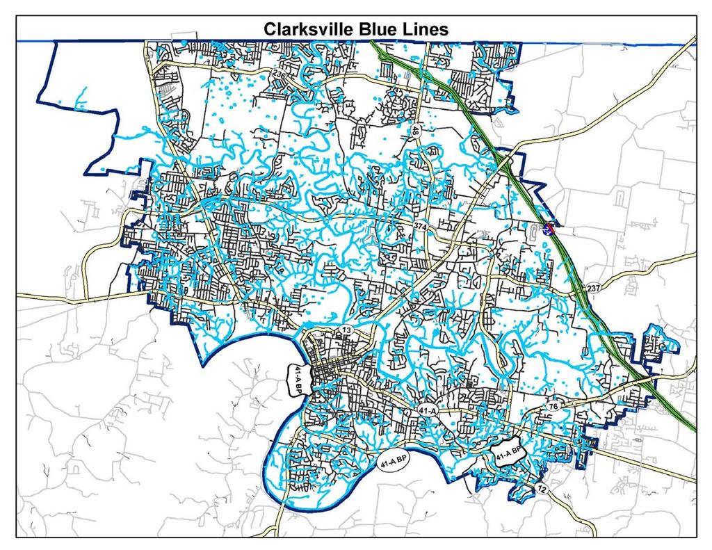
350
Chapter 4. Drainage Report and Construction Drawing Submittal Requirements
 4.0 Introduction The requirements presented in this section shall be used to aid the design engineer or applicant in the preparation of drainage reports, drainage studies, and construction drawings for
3.0 Planning and Submittal Requirements
 October 2003, Revised February 2005 Chapter 3.0, Planning and Submittal Requirements Page 1 3.0 Planning and Submittal Requirements 3.1 Drainage Studies and Drawings The City of Greenwood Village (Village)
Stormwater Management Studies PDS Engineering Services Division ES Policy # 3-01
 Stormwater Management Studies PDS Engineering Services Division Revised Date: 2/28/08 INTRODUCTION The City of Overland Park requires submission of a stormwater management study as part of the development
CHAPTER 8 EROSION AND SEDIMENT CONTROL PLAN REQUIREMENTS
 CHAPTER 8 EROSION AND SEDIMENT CONTROL PLAN REQUIREMENTS 8.1 INTRODUCTION To minimize the detrimental effects of erosion and sedimentation, Henrico County requires that those individuals responsible for
iswm TM Criteria Manual City of Azle Section 14 City of Azle Subdivision Ordinance DRAFT-June Chapter 1
 City of Azle Section 14 City of Azle Subdivision Ordinance DRAFT-June 2010... Chapter 1 i CITY OF AZLE iswm CRITERIA MANUAL FOR SITE DEVELOPMENT AND CONSTRUCTION Incorporating the Regional NCTCOG Integrated
Understanding Stormwater Pollution Prevention Plans (SWPPPs) (SWPPPS)
 (SWPPPS)") Understanding Stormwater Pollution Prevention Plans (SWPPPs) (SWPPPS) Definitions SWPPP: Storm Water Pollution Prevention Plan BMP: Best Management Practice(s) to control pollution IDNR: Iowa Department
Understanding Stormwater Pollution Prevention Plans (SWPPPs) (SWPPPS) Definitions SWPPP: Storm Water Pollution Prevention Plan BMP: Best Management Practice(s) to control pollution IDNR: Iowa Department
Chapter 21 Stormwater Management Bylaw
 Chapter 21 Stormwater Management Bylaw SECTION 1. PURPOSE The purpose of this Bylaw is to: implement the requirements of the National Pollutant Discharge Elimination System (NPDES) General Permit for Storm
Chapter 6. Hydrology. 6.0 Introduction. 6.1 Design Rainfall
 6.0 Introduction This chapter summarizes methodology for determining rainfall and runoff information for the design of stormwater management facilities in the City. The methodology is based on the procedures
Stormwater Local Design Manual For Houston County, Georgia
 Stormwater Local Design Manual For Houston County, Georgia Adopted November 15, 2005 TABLE OF CONTENTS 1. FORWARD... 1 2. GENERAL LEVEL OF SERVICE STANDARDS... 2 2.1. DETENTION REQUIREMENTS... 2 2.1.1.
Project Drainage Report
 Design Manual Chapter 2 - Stormwater 2A - General Information 2A-4 Project Drainage Report A. Purpose The purpose of the project drainage report is to identify and propose specific solutions to stormwater
CITY UTILITIES DESIGN STANDARDS MANUAL
 CITY UTILITIES DESIGN STANDARDS MANUAL () September 2017 Page Chapter 1 Acronyms and Definitions 1.01 Purpose 1 1.02 Acronyms 1 1.03 Definitions 3 Chapter 2 Introduction 2.01 Purpose 1 2.02 Applicability
NEW CASTLE CONSERVATION DISTRICT. through. (Name of Municipality) PLAN REVIEW APPLICATION DRAINAGE, STORMWATER MANAGEMENT, EROSION & SEDIMENT CONTROL
 PLAN REVIEW APPLICATION DRAINAGE, STORMWATER MANAGEMENT, EROSION & SEDIMENT CONTROL") NEW CASTLE CONSERVATION DISTRICT through (Name of Municipality) PLAN REVIEW APPLICATION DRAINAGE, STORMWATER MANAGEMENT, EROSION & SEDIMENT CONTROL Office use only: Received by Municipality: Received by
NEW CASTLE CONSERVATION DISTRICT through (Name of Municipality) PLAN REVIEW APPLICATION DRAINAGE, STORMWATER MANAGEMENT, EROSION & SEDIMENT CONTROL Office use only: Received by Municipality: Received by
CRITERIA FOR STORMWATER DESIGN
 ..CHAPTER.. CRITERIA FOR STORMWATER DESIGN 2.1 Integrated Site Design Approach 2.1.1 Introduction This chapter represents the requirements, policies and other guidance for stormwater management design
MODEL Stormwater Local Design Manual. City of Centerville
 MODEL Stormwater Local Design Manual City of Centerville Adopted December 6, 2005 TABLE OF CONTENTS 1. FORWARD... 1 2. GENERAL LEVEL OF SERVICE STANDARDS... 1 2.1. DETENTION REQUIREMENTS... 1 2.1.1. Discharge
Ordinance No Lot Surface Drainage
 Ordinance No. 35-2008 - Lot Surface Drainage The Township has adopted a new Lot Surface Drainage Ordinance which amends Chapter 170, Article IX, Subdivision and Site Plan Review by adding a new Section
E. STORMWATER MANAGEMENT
 E. STORMWATER MANAGEMENT 1. Existing Conditions The Project Site is located within the Lower Hudson Watershed. According to the New York State Department of Environmental Conservation (NYSDEC), Lower Hudson
SECTION 3 DRAINAGE. 3-1 General. 3-2 Drainage Ordinances and Legal Requirements
 SECTION 3 DRAINAGE 3-1 General All Drainage plans for proposed development shall be prepared by a Professional Engineer registered in Virginia, except as noted below. Further, their seal and signature
FACT SHEET GENERAL KPDES PERMIT FOR STORM WATER POINT SOURCE DISCHARGES CONSTRUCTION ACTIVITIES
 FACT SHEET GENERAL KPDES PERMIT FOR STORM WATER POINT SOURCE DISCHARGES CONSTRUCTION ACTIVITIES 1. COVERAGE UNDER THIS GENERAL PERMIT Area of Coverage: This permit covers all areas of the Commonwealth
Richland County Department of Public Works Engineering (Land Development) Division
 Division") Richland County Department of Public Works Engineering (Land Development) Division Commercial Projects What is a Commercial Project? Projects that are not related to residential single family homes and/or
Richland County Department of Public Works Engineering (Land Development) Division Commercial Projects What is a Commercial Project? Projects that are not related to residential single family homes and/or
ARTICLE A. POST-DEVELOPMENT STORMWATER MANAGEMENT FOR NEW DEVELOPMENT AND REDEVELOPMENT
 CHAPTER 11. STORMWATER MANAGEMENT ARTICLE A. POST-DEVELOPMENT STORMWATER MANAGEMENT FOR NEW DEVELOPMENT AND REDEVELOPMENT DIVISION 1. GENERALLY Sec. 10-11001. FINDINGS It is hereby determined that: (1)
STORMWATER DEVELOPMENT GUIDELINES
 1600 Battle Creek Road, Morrow, Georgia 30260 STORMWATER DEVELOPMENT GUIDELINES Second Edition November 2006 Program Management & Engineering Department Office: (770) 961-2130 Fax: (770) 960-5229 STORMWATER
DESIGN BULLETIN #16/2003 (Revised July 2007) Drainage Guidelines for Highways Under Provincial Jurisdiction in Urban Areas.
 Drainage Guidelines for Highways Under Provincial Jurisdiction in Urban Areas.") Drainage Guidelines for Highways Under Provincial Jurisdiction in Urban Areas. July 2007 Update to Design Bulletin #16/2003: Added under Design Criteria Culverts of 600mm diameter are commonly used to
Drainage Guidelines for Highways Under Provincial Jurisdiction in Urban Areas. July 2007 Update to Design Bulletin #16/2003: Added under Design Criteria Culverts of 600mm diameter are commonly used to
16.0 Water Quality Management Criteria for Developed Land
 October 2003, Revised February 2005 Criteria for Developed Land Page 1 16.1 Introduction 16.0 Water Quality Management Criteria for Developed Land Stormwater quality control is an integral part of any
New Castle County, DE. Floodplain Regulations
 New Castle County, DE Floodplain Regulations John J. Gysling, PE CFM Department of Land Use New Castle County, DE February 26, 2009 Today s Presentation Floodplain Protection and Uses Terms and Definitions
SECTION 11: REGULATORY FLOODWAYS
 SECTION 11: REGULATORY FLOODWAYS Contents 11.1. The Floodway... 11-2 11.1.1. The floodway concept... 11-2 11.1.2. Floodway map... 11-2 11.1.3. Floodway permitting... 11-3 11.1.4. Changing the floodway...
Chapter 2 ADMINISTRATIVE PROCEDURES
 Chapter 2 2.01 General 2.01.1 Application of Chapter 2.01.2 Fees 2.02 Pre-Development Site Certification and Assessment 2.03 Construction Permits 2.03.1 Site Development Permit 2.03.2 Development Permits
SECTION STORM DRAINAGE DESIGN, GRADING, AND WATER QUALITY TECHNICAL CRITERIA TABLE OF CONTENTS PAGE 402 STORM DRAINAGE DESIGN CRITERIA 400-1
 CITY OF THORNTON Standards and Specifications Revised: October 2012 SECTION 400 - STORM DRAINAGE DESIGN, GRADING, AND WATER QUALITY TECHNICAL CRITERIA TABLE OF CONTENTS PAGE 401 GENERAL PROVISIONS 400-1
STORMWATER RUNOFF AND WATER QUALITY IMPACT REVIEW
 SUBCHAPTER 8 STORMWATER RUNOFF AND WATER QUALITY IMPACT REVIEW 7:45-8.1 Purpose and scope of review Except for those projects expressly exempted by this chapter or waived by the Commission, the Commission
PART 3 - STANDARDS FOR SEWERAGE FACILITIES DESIGN OF STORM SEWERS
 PART 3 - STANDARDS FOR SEWERAGE FACILITIES 3.3 - DESIGN OF STORM SEWERS 3.301 Design of Storm Sewers A. General Information B. Investigations and Surveys C. Special Projects 3.302 Design Criteria for Storm
Spartanburg County. Storm Water Management Design Manual
 Spartanburg County TABLE OF CONTENTS Section Title Page No. Table of Contents... i List of Tables......iii Chapter 1 Introduction... 1 1.1 Purpose of the Manual... 1 1.2 Description and Use of the Manual...
S.O.P. No. HMD
 Page: 1 of 9 PURPOSE: To establish (SOP) for submission requirements, review process and approval of applications for Non-vehicular Access Permits for the purpose of connection or discharge to any MassDOT
SECTION 4 SURFACE WATER MANAGEMENT DESIGN AND CONSTRUCTION REQUIREMENTS
 SECTION 4 SURFACE WATER MANAGEMENT DESIGN AND CONSTRUCTION REQUIREMENTS Page 4-1 INTRODUCTION 4-3 4-1.01 Applicability of VMCs 14.24, 14.25, 14.26 4-4 4-1.02 Minimum Requirements - Projects Below Threshold
STORMWATER AND EROSION CONTROL PERMIT
 STORMWATER MANAGEMENT AND EROSION CONTROL PERMIT INSTRUCTIONS AND INFORMATION Any project that involves the disturbance of ANY quantity of land requires the applicant to receive approval for the project
CHAPTER 6 ADDITIONAL STANDARDS APPLYING TO SHORELAND AREAS AND PUBLIC WATERS
 CHAPTER 6 ADDITIONAL STANDARDS APPLYING TO SHORELAND AREAS AND PUBLIC WATERS Section 1 Intent. 49 Section 2 Floodplain Requirements 49 Section 3 Water-Oriented Accessory Structures 50 Section 4 Stairways,
CITY OF SPRING HILL Water Quality Buffer Zone Policy (Adopted April 22, 2008)
") Section I - Description CITY OF SPRING HILL Water Quality Buffer Zone Policy (Adopted April 22, 2008) A water quality buffer zone (a.k.a. a riparian zone) is a strip of undisturbed native (indigenous)
Section I - Description CITY OF SPRING HILL Water Quality Buffer Zone Policy (Adopted April 22, 2008) A water quality buffer zone (a.k.a. a riparian zone) is a strip of undisturbed native (indigenous)
City of Tulsa. Stormwater Design Criteria Manual
 City of Tulsa Stormwater Design Criteria Manual 2014 Table of Contents Chapter 100 EXECUTIVE SUMMARY... 101 101 INTRODUCTION... 101 101.1 Manual Organization... 101 101.2 Manual Contents... 101 101.2.1
COON CREEK WATERSHED DISTRICT PERMIT REVIEW. Spring Lake Park Schools Westwood Middle School st Avenue NE, Spring Lake Park, MN 55432
 PAN 16-112, Westwood Middle School, Page 1 of 6 COON CREEK WATERSHED DISTRICT PERMIT REVIEW MEETING DATE: August 22, 2016 AGENDA NUMBER: 10 FILE NUMBER: 16-112 ITEM: Westwood Middle School RECOMMENDATION:
Ordinance amending the San Francisco Public Works Code by adding Article 4.2,
 FILE NO. ORDINANCE NO. 1 [Stormwater Management.] Ordinance amending the San Francisco Public Works Code by adding Article., sections., requiring the development and maintenance of stormwater management
POLICY FOR NATURAL RESOURCE MANAGEMENT AREAS
 POLICY FOR NATURAL RESOURCE MANAGEMENT AREAS I. POLICY STATEMENT Auburn University's (the University's) "Policy for Natural Resource Management Areas" implements the Campus Master Plan Land Use Element
Chapter 8. Inlets. 8.0 Introduction. 8.1 General
 . Introduction This chapter provides criteria and design guides for evaluating and designing storm sewer inlets in the City of Centennial. The review of all planning submittals will be based on the criteria
Ingham County Drain Commissioner Patrick E. Lindemann 707 BUHL AVENUE P. O. BOX 220 MASON MI PH. (517) FAX (517)
 FAX (517)") Date Issued Ingham County Drain Commissioner Patrick E. Lindemann 707 BUHL AVENUE P. O. BOX 220 MASON MI 48854 PH. (517) 676-8395 FAX (517) 676-8364 APPLICATION FOR SOIL EROSION AND SEDIMENTATION POLLUTION
Date Issued Ingham County Drain Commissioner Patrick E. Lindemann 707 BUHL AVENUE P. O. BOX 220 MASON MI 48854 PH. (517) 676-8395 FAX (517) 676-8364 APPLICATION FOR SOIL EROSION AND SEDIMENTATION POLLUTION
Erosion & Sedimentation Control Policy
 Issue Date 10/22/2010 Page 1 of 8 Erosion & Sedimentation Control Policy Introduction: Soil erosion is the removal of soil by water, wind, ice or gravity and sediment deposition occurs when the rate of
City of Morristown. Stormwater Program Standard Operating Procedures. Stormwater Design Guidance Manual. April 1, 2016.
 City of Morristown Stormwater Program Standard Operating Procedures Stormwater Design Guidance Manual April 1, 2016 -Prepared By- City of Morristown 100 West First North Street Morristown, TN 37814 (423)
CHAPTER 2 STORMWATER MANAGEMENT
 CHAPTER 2 STORMWATER MANAGEMENT REVISED SEPTEMBER 11, 2002 WHATCOM COUNTY DEVELOPMENT STANDARDS CHAPTER 2 - STORMWATER MANAGEMENT TABLE OF CONTENTS PART 1: ADMINISTRATIVE PROVISIONS Section 201. Regulatory
City of Elgin SUBDIVISION FINAL ENGINEERING Engineering Submittal Checklist
 If this is a re-submittal, please provide a point-by-point response to previous review comments, identifying how each comment has been addressed, location in the plan set of the changes made to address
RESIDENTIAL BUILDING PERMIT
 A APPLICATION FOR A RESIDENTIAL BUILDING PERMIT JACKSON CO. MS. PLAN CASE NUMBER: PERMIT NUMBER: ACCEPTED BY: APPROVED BY: Application is hereby made for a permit under the provisions of the Comprehensive
TxDOT Houston District Permit Requirements (Information contained herein is subject to change)
") Houston District Permit Requirements (Information contained herein is subject to change) Access Driveway for Commercial / Industrial Developments; or Street Tie-In / Drainage-Only 1) Complete the three
Houston District Permit Requirements (Information contained herein is subject to change) Access Driveway for Commercial / Industrial Developments; or Street Tie-In / Drainage-Only 1) Complete the three
APPENDIX H Guidance for Preparing/Reviewing CEQA Initial Studies and Environmental Impact Reports
 APPENDIX H H.1 Guidance for Preparing and Reviewing CEQA Initial Studies Step 1: Consider the Project Characteristics as Provided by the Project Applicant Review the project application and draft plan
FIRM NAME DESIGNER: CHECKER: DATE: FPID #: DESCRIPTION: COUNTY: DRAINAGE DESIGN CHECKLIST. Designers Initials. Checkers Initials.
 I. Drainage Report A. Executive Summary - Brief Overview of Project Drainage Design B. Project Description 1. Existing Conditions 2. Proposed Project Conditions 3. Project Justification Narrative - Basin
EROSION, SEDIMENTATION, ETC
 EROSION, SEDIMENTATION, ETC. 19-61 ARTICLE V. WATER QUALITY REVIEW IN SPECIAL PROTECTION AREAS. Sec. 19-60. Findings and purpose. (a) The County Council finds that streams, rivers, wetlands, and other
Chapter 11 Culverts and Bridges
 Chapter 11 Culverts and Bridges Contents 1.0 Introduction... 1 2.0 General Design... 1 2.1 Design Criteria... 1 2.2 Design Flows... 1 2.3 Permitting and Regulations... 1 2.4 Aesthetics and Safety... 2
ENVIRONMENTAL RESOURCE PERMIT APPLICATION
 ENVIRONMENTAL RESOURCE PERMIT APPLICATION SOUTHWEST FLORIDA WATER MANAGEMENT DISTRICT 2379 BROAD STREET, BROOKSVILLE, FL 34604-6899 (352) 796-7211 OR FLORIDA WATS 1 (800) 423-1476 SECTION E INFORMATION
Water Quality: 1.0 Water Quality Protection Volume and Peak Flow 2.0 Construction SWP3 Guidelines and Form
 : 1.0 Protection Volume and Peak Flow 2.0 and Form Table of Contents 1.0 Protection Volume and Peak Flow...WQ-1 1.1 Introduction...WQ-1 1.2 Protection Volume Calculation...WQ-1 1.3 Protection Volume Reduction
JEFFERSON COUNTY STORM WATER MANAGEMENT
 JEFFERSON COUNTY STORM WATER MANAGEMENT B-210 Courthouse, Birmingham, Alabama 35203 Telephone: (205) 325-8741 Erosion and Sedimentation Control Measures for Commercial Projects (Plans Requirements) -All
Belmont County Erosion & Sediment Control Regulations
 Belmont County Erosion & Sediment Control Regulations 1. Purpose and Scope The Belmont County Board of Commissioners adopts these erosion and sediment control regulations pursuant to Ohio Revised Code
PLANNED UNIT DEVELOPMENT, PLANNING APPROVAL & SUBDIVISION STAFF REPORT Date: June 4, 2015
 PLANNED UNIT DEVELOPMENT, PLANNING APPROVAL & SUBDIVISION STAFF REPORT Date: June 4, 2015 NAME SUBDIVISION NAME CC Williams Plant Subdivision CC Williams Plant Subdivision LOCATION CITY COUNCIL DISTRICT
STORM DRAINAGE DESIGN CRITERIA
 BWM Orig. 01/01/05 Revised 01/01/10 LUCAS COUNTY ENGINEERS OFFICE STORM DRAINAGE DESIGN CRITERIA Drainage The design of storm sewer systems will be based upon the Rational Method using the equation Q=CiA
Module 3. Module 3a. As of July : A lot of local ESC ordinances are out of date! Virginia Erosion & Sediment Control Program
 Module 3. Virginia Erosion & Sediment Control Program Module 3a. Statutory and Regulatory Requirements: Virginia Erosion and Sediment Control Law and Regulations As of July 1 2013: A lot of local ESC ordinances
6.0 Runoff. 6.1 Introduction. 6.2 Flood Control Design Runoff
 October 2003, Revised February 2005 Chapter 6.0, Runoff Page 1 6.1 Introduction 6.0 Runoff The timing, peak rates of discharge, and volume of stormwater runoff are the primary considerations in the design
RULES OF GEORGIA DEPARTMENT OF NATURAL RESOURCES ENVIRONMENTAL PROTECTION DIVISION CHAPTER EROSION AND SEDIMENTATION CONTROL TABLE OF CONTENTS
 RULES OF GEORGIA DEPARTMENT OF NATURAL RESOURCES ENVIRONMENTAL PROTECTION DIVISION CHAPTER 391-3-7 EROSION AND SEDIMENTATION CONTROL TABLE OF CONTENTS 391-3-7.01 Definitions. 391-3-7.02 (Repealed) 391-3-7.03
7/16/2012. Post Construction Best Management Practices (PCBMPs) Article VIII: Post Construction Best Management Practices
 Article VIII: Post Construction Best Management Practices") Post Construction Best Management Practices (PCBMPs) Article VIII: Post Construction Best Management Practices Presented by Jennifer Boyer DuPage County DEC Includes BMPs intended to provide volume control
Post Construction Best Management Practices (PCBMPs) Article VIII: Post Construction Best Management Practices Presented by Jennifer Boyer DuPage County DEC Includes BMPs intended to provide volume control
TECHNICAL CONTENT PROPOSED STEEP SLOPE REGULATION
 1 TECHNICAL CONTENT PROPOSED STEEP SLOPE REGULATION Draft 2/08/10 (Revised 02-14-11,Revised 02-21-11, Revised 03-03-11, Revised 04-19-11, Revised 04-20-11, Revised 05-05-11, Revised 05-09-11). DEFINITIONS
Pre-Treatment Bioretention Cells Bioswales IOWA STORMWATER MANAGEMENT MANUAL DECEMBER 16, 2015
 Pre-Treatment Bioretention Cells Bioswales IOWA STORMWATER MANAGEMENT MANUAL DECEMBER 16, 2015 Urban Runoff Background How we got here What Problem?? Provenance of the Problem Unified Sizing Criteria What
Pennsylvania Stormwater Best Management Practices Manual. Chapter 3. Stormwater Management Principles and Recommended Control Guidelines
 Pennsylvania Stormwater Best Management Practices Manual Chapter 3 Stormwater Management Principles and Recommended Control Guidelines 363-0300-002 / December 30, 2006 Chapter 3 Stormwater Management Principles
This ordinance applies to the entire unincorporated areas of Waupaca County.
 REPEAL AND RECREATE CHAPTER 10, SECTION 10.50 OF THE WAUPACA COUNTY CODE OF ORDINANCES RELATING TO MANURE STORAGE AND LAND SPREADING OF MANURE MANURE MANAGEMENT 10.50 GENERAL PROVISIONS A. Title: This
Municipal Stormwater Ordinances Summary Table
 APPENDIX F Municipal Ordinances Summary Table Municipality Abington Bryn Athyn Borough Hatboro Borough Ordinance, SALDO Runoff equals pre post Erosion Sediment Control Water Quality Requirements Any which
Module 4 Regulatory requirements for Land Disturbing Activities
 Module 4 Regulatory requirements for Land Disturbing Activities MODULE 4 REGULATORY REQUIREMENTS FOR A LDA Module 4a Overview MODULE 4A REGULATORY REQUIREMENTS FOR A LDA ESC Regulations Overview 1990 First
EAST NANTMEAL TOWNSHIP STORMWATER MANAGEMENT, GRADING & EROSION CONTROL ORDINANCE
 EAST NANTMEAL TOWNSHIP STORMWATER MANAGEMENT, GRADING & EROSION CONTROL ORDINANCE Ordinance No. adopted February 12, 2014 EAST NANTMEAL TOWNSHIP CHESTER COUNTY, PENNSYLVANIA TABLE OF CONTENTS PAGE ARTICLE
Ordinance No. 1365C Stormwater Management and Clean Water Regulations Ordinance for
 Ordinance No. 1365C Stormwater Management and Clean Water Regulations Ordinance for LAKE COUNTY DRAINAGE BOARD GERRY SCHEUB, CHAIRMAN ROOSEVELT ALLEN JR., MEMBER MICHAEL C. REPAY, MEMBER LAKE COUNTY SURVEYOR
STATE OF FLORIDA DEPARTMENT OF ENVIRONMENTAL PROTECTION GENERIC PERMIT FOR DISCHARGE OF STORMWATER FROM PHASE II
 STATE OF FLORIDA DEPARTMENT OF ENVIRONMENTAL PROTECTION GENERIC PERMIT FOR DISCHARGE OF STORMWATER FROM PHASE II MUNICIPAL SEPARATE STORM SEWER SYSTEMS May 1, 2003 1 Generic Permit for Discharge of Stormwater
INFRASTRUCTURE ELEMENT STORMWATER SUB-ELEMENT GOALS, OBJECTIVES & POLICIES
 INFRASTRUCTURE ELEMENT STORMWATER SUB-ELEMENT GOALS, OBJECTIVES & POLICIES GOALS, OBJECTIVES & POLICIES GOAL DR 1: STORMWATER MANAGEMENT/DRAINAGE SYSTEMS. It is the goal of the City of Casselberry to provide
Review of State and Federal Stormwater Regulations November 2007
 Review of State and Federal Stormwater Regulations November 2007 By: James T. Spaulding, PE, CPESC Joseph M. Ducharme, Jr., PE TTG ENVIRONMENTAL CONSULTANTS, LLC 27 LOCKE ROAD, CONCORD, NH 03301-5301 TELEPHONE:
CHAPTER 7 - INFRASTRUCTURE INSPECTION AND ACCEPTANCE... 2
 CHAPTER 7 - INFRASTRUCTURE INSPECTION AND ACCEPTANCE... 2 7.1. GENERAL.... 2 7.1.1. Inspection Restriction Dates.... 2 7.1.2. Complete Improvements.... 2 7.1.3. Public Improvements.... 2 7.1.4. Warranty
Municipal Stormwater Management Planning
 Municipal Stormwater Management Planning Christopher C. Obropta, Ph.D., P.E. Water Resources Extension Specialist with Rutgers Cooperative Extension Assistant Professor with Department of Environmental
ARTICLE V: STORMWATER MANAGEMENT AND DRAINAGE SYSTEMS
 ARTICLE V: STORMWATER MANAGEMENT AND DRAINAGE SYSTEMS Section 501: Purpose An adequate drainage system including necessary ditches, pipes, culverts, drains, inlets, bridges, detention ponds, etc. shall
DESIGN AND MAINTENANCE OF STRUCTURAL BMPS
 ..CHAPTER.. DESIGN AND MAINTENANCE OF STRUCTURAL BMPS Structural stormwater best management practices (BMPs) are engineered facilities that are intended to treat stormwater runoff. This chapter provides
Chatham Park Stormwater Manual
 Chatham Park Stormwater Manual Table of Contents A. Introduction... 2 B. Calculation Methods... 2 C. BMP Design Standards... 3 D. Compliance Points... 3 E. Critical Environmental Resources... 3 F. Submittal
Stormwater Management Technical Manual
 Public Works Department Stormwater Management Technical Manual October 2015 HillsboroughCounty.org PREFACE The following text contains current information for designing and submitting construction plans
Stormwater Quality Extended Detention Basin Operation and Maintenance (O&M) Manual. for: Located at: Prepared for: Prepared by:
 Manual. for: Located at: Prepared for: Prepared by:") Stormwater Quality Extended Detention Basin Operation and Maintenance (O&M) Manual for: Insert Development Name Located at: Insert Address Prepared for: Insert Property Owner Name, Address, and Phone Number
Stormwater Quality Extended Detention Basin Operation and Maintenance (O&M) Manual for: Insert Development Name Located at: Insert Address Prepared for: Insert Property Owner Name, Address, and Phone Number
PRELIMINARY DRAINAGE REPORT NEWCASTLE FIRE STATION OLD STATE HIGHWAY
 PRELIMINARY DRAINAGE REPORT FOR THE NEWCASTLE FIRE STATION OLD STATE HIGHWAY PREPARED FOR THE NEWCASTLE FIRE PROTECTION DISTRICT JULY 2014 BY ROSEVILLE DESIGN GROUP, INC. ROSEVILLE DESIGN GROUP, Inc Established
Constructed Wetland Pond T-8
 Constructed Wetland Pond T-8 Description A constructed wetlands pond is a shallow retention pond designed to permit the growth of wetland plants such as rushes, willows, and cattails. Constructed wetlands
ILLICIT DISCHARGE, STORM WATER INFLOW TO THE POTW, AND ILLEGAL CONNECTION CONTROL.
 1482.09 ILLICIT DISCHARGE, STORM WATER INFLOW TO THE POTW, AND ILLEGAL CONNECTION CONTROL. (a) Purpose and Scope. The purpose of this regulation is to provide for the health, safety, and general welfare
North Carolina Sedimentation Control Law
 1 North Carolina Sedimentation Control Law North Carolina Sediment Control Law 1 North Carolina Sedimentation Control Law The purpose of this section is to highlight the portions of the North Carolina
Hydrologic Study Report for Single Lot Detention Basin Analysis
 Hydrologic Study Report for Single Lot Detention Basin Analysis Prepared for: City of Vista, California August 18, 2006 Tory R. Walker, R.C.E. 45005 President W.O. 116-01 01/23/2007 Table of Contents Page
City of Gig Harbor Stormwater Management and Site Development Manual
 City of Gig Harbor Stormwater Management and Site Development Manual Volume I Minimum Technical Requirements and Site Planning Prepared by: Pierce County Surface Water Management Approved by City of Gig
CHAPTER 9 STORMWATER MANAGEMENT PLAN REQUIREMENTS
 CHAPTER 9 9.1 INTRODUCTION The Virginia Stormwater Management Program (VSMP) Act and Regulations require that Henrico County adopt a local program to administer the requirements. The requirements are addressed
Article 20: Erosion Control and Stormwater Management
 Article 20: Erosion Control and Stormwater Management Section 360: Purpose, Scope of Authority, Performance Guarantee and Approvals A. Purpose. The purpose of this document is to set forth minimum requirements
2A Stormwater Regulations and Permitting A. Iowa Drainage Law and Resources 1 B. Regulated Activities 1
 Design Manual Chapter 2 - Stormwater Table of Contents TOC Table of Contents Chapter 2 - Stormwater 2A General Information 2A-1--------------------------------General Information A. Concept... 1 B. Informing
Chapter 7. Street Drainage. 7.0 Introduction. 7.1 Function of Streets in the Drainage System. 7.2 Street Classification
 7. Introduction This chapter summarizes methods to evaluate runoff conveyance in various street cross sections and curb types in the Town of Castle Rock and identifies acceptable upper limits of street
Chapter 3 Dispersion BMPs
 Chapter 3 Dispersion BMPs 3.1 BMP L611 Concentrated Flow Dispersion 3.1.1 Purpose and Definition Dispersion of concentrated flows from driveways or other pavement through a vegetated pervious area attenuates
Constructed Wetland Use in Nonpoint Source Control
 Constructed Wetland Use in Nonpoint Source Control Description Constructed wetlands are excavated basins with irregular perimeters and undulating bottom contours into which wetland vegetation is purposely
SECTION 17.1 STORMWATER MANAGEMENT AND EROSION CONTROL
 SECTION 17.1 STORMWATER MANAGEMENT AND EROSION CONTROL Subdivision 1: Purpose Subdivision 2: Scope Subdivision 3: Definitions Subdivision 4: Permit Application and Plan Subdivision 5: Stormwater Pollution
HYDROLOGIC CONSIDERATIONS. 22 nd Annual Nonpoint Source Pollution Conference Saratoga Springs, NY
 LOW IMPACT DEVELOPMENT HYDROLOGIC CONSIDERATIONS 22 nd Annual Nonpoint Source Pollution Conference Saratoga Springs, NY May 18, 2011 PRESENTATION AGENDA Introduction Definitions Discuss Impacts to Hydrologic
Soil Erosion Control Soil Erosion Control
 Ordinance 1 FILLMORE COUNTY SOIL EROSION CONTROL ORDINANCE ADOPTED 1982 AMENDED 1990 AMENDED 1994 AMENDED 1996 2 FILLMORE COUNTY SOIL EROSION CONTROL ORDINANCE AN ORDINANCE REQUIRING THAT FARMING PRACTICES
FLORENCE COUNTY STORMWATER DESIGN MANUAL
 FLORENCE COUNTY STORMWATER DESIGN MANUAL JULY 18, 2013 Resolution No. 02-2013/14 Florence County Council TABLE OF CONTENTS TITLE PAGE NO. SECTION 1. GENERAL 1.1 INTRODUCTION--------------------------------------------------------------------------
HYDROLOGIC-HYDRAULIC STUDY ISABELLA OCEAN RESIDENCES ISLA VERDE, CAROLINA, PR
 HYDROLOGIC-HYDRAULIC STUDY ISABELLA OCEAN RESIDENCES ISLA VERDE, CAROLINA, PR 1 INTRODUCTION 1.1 Project Description and Location Isabella Ocean Residences is a residential development to be constructed
DRAINAGE DESIGN DOCUMENTATION
 June, 2017 DRAINAGE DESIGN DOCUMENTATION (An expansion of the Stormwater Management Design Report) Note: This report outline is not all-inclusive. There may be situations when information not included
901 STORMWATER POLLUTION MANAGEMENT SECTION 901 STORMWATER POLLUTION MANAGEMENT
 SECTION 901 STORMWATER POLLUTION MANAGEMENT 901.1 DESCRIPTION Design, implement, inspect and maintain appropriate best management practices to minimize or eliminate erosion, sediment and other pollutants
Elements of the Storm Water Management Plan. Storm Water Pollution Prevention Plan (SWPPP)
") Elements of the Storm Water Management Plan Storm Water Pollution Prevention Plan (SWPPP) Small Construction Site Storm Water Management Rodney Hendrick Water Quality Specialist LSU Ag Center Plan Requirements
Elements of the Storm Water Management Plan Storm Water Pollution Prevention Plan (SWPPP) Small Construction Site Storm Water Management Rodney Hendrick Water Quality Specialist LSU Ag Center Plan Requirements
ENVIRONMENTAL RESOURCE PERMIT APPLICANT S HANDBOOK VOLUME II (Design and Performance Standards Including Basin Design and Criteria)
") ENVIRONMENTAL RESOURCE PERMIT APPLICANT S HANDBOOK VOLUME II (Design and Performance Standards Including Basin Design and Criteria) FLORIDA DEPARTMENT OF ENVIRONMENTAL PROTECTION Volume II (including Appendices
ENVIRONMENTAL RESOURCE PERMIT APPLICANT S HANDBOOK VOLUME II (Design and Performance Standards Including Basin Design and Criteria) FLORIDA DEPARTMENT OF ENVIRONMENTAL PROTECTION Volume II (including Appendices