Proposed Facility Study Report. Project: A380_A383_A415_A414_A413 MISO # F088. Prepared for Midwest ISO
|
|
|
- Ginger Sharp
- 6 years ago
- Views:
Transcription

1 Proposed Facility Study Report Project: A380_A383_A415_A414_A413 MISO # F088 Prepared for Midwest ISO January 15 th, 2010 Great River Energy Contact: Greg Schutte, Project Manager Great River Energy 1
2 Table of Contents Section Title 1 Overview i. Facility Study Summary 2 System Upgrades Design Summaries i. Stand Alone System Upgrades a. None ii. Non-Stand Alone System Upgrades a. Stanton Substation iii. b. Coal Creek Substation Interconnection Facilities a. None 3 Right of Way Requirements (Not Applicable to this Study) 4 Exhibits A1 Customer One-line and Site Map (Not Applicable to this Study) A2 A3 Transmission Owner One-Line A2-1 Stanton One-Line Diagram (S031-01ER31) A2-2 Coal Creek One-Line Diagram (S061-01E1AR40) Site Plan A3-1 Stanton General Arrangement (S031-04E01R10) A3-2 Stanton Sectional View (S031-04E02R02) A3-3 Coal Creek General Arrangement (S061-04E02R09) A3-4 Coal Creek Sectional View (S061-04D07R02) A3-5 Coal Creek Sectional View (S061-04D12R03) A3-6 Coal Creek Sectional View (S061-04D14R02) A3-7 Coal Creek Sectional View (S061-04D17R05) A4 A5 A6 Transmission Line Plan & Profile (Not Applicable to this Study) Facilities to be constructed by Transmission Owner Detailed Cost of Facilities to be constructed by the Transmission Owner A6-1 Stanton Substation Network Upgrades A6-2 Coal Creek Substation Network Upgrades 2
3 A7 A8 A9 A10 A11 A12 A13 A14 Facilities to be constructed by Customer (Not Applicable to this Study) Detailed Cost of Facilities to be constructed by the Customer (Not Applicable to this Study) Facilities subject to Transmission Owner reimbursement Contingent Facilities (Not Applicable to this Study) Customer & Transmission Owner Milestones Construction & Coordination Schedules Permits, Licenses, Regulatory Approvals and Authorization (Not Applicable to this Study) Interconnection and Operating Guidelines 3
4 1. Overview of the Project This project consists of upgrades to the Great River Energy (GRE) (the Transmission Owner) owned Coal Creek and Stanton Substation 230kV SV line termination. Great River Energy is defined as the Transmission Owner and Balancing Authority for the purpose of this report. i. Facility Study Summary In accordance with the Interconnection Facility Study Proposal submitted to Midwest Independent System Operator (MISO) by the Transmission Owner, Great River Energy has provided an estimate for the performance of an Interconnection Facility Study (FS) for the Transmission Service Request designated F088. This FS report is based on the request by MISO and the Customer with a selected option of a +/-20% estimate within 90 days from receipt of purchase order and signed Scope of Authorization. This FS report is being prepared and submitted to MISO. This FS report documents the required facility upgrades to the Transmission Owner s substation and transmission line facilities required to connect the Customer s generation facilities as identified in project F088. The network upgrades include stand alone upgrades and non-stand alone upgrades. The stand alone upgrades are those that can be constructed or installed with no interface to the Owner s existing facilities. There are no stand alone network upgrades associated with F088. Non-stand alone network upgrades are those that require interface with the Owner in order to proceed with the installation. All required upgrades due to the addition of F088 are non-stand alone network upgrades. The interconnection facilities are upgrades that will be 100% funded by the Interconnection Customer and will be designed, procured, constructed and owned by the Transmission Owner at the point of interconnection on the Transmission Owner s Facility. There are no interconnection facilities for GRE for this project. Customer owned facilities are not detailed in this report. 4
5 2. System Upgrades i. Stand Alone System Upgrade There are no stand alone system upgrades. ii. Non-Stand Alone System Upgrades a. Stanton Substation Project Location: This project is located at the Stanton Substation which is located in Government Lot 6 in Section 16, Township 144, Range 84, Mercer County, North Dakota Project Overview: The Scope of work for this portion of the project includes improvements to the Transmission Owner Stanton Substation owned by Great River Energy in order to accommodate the increased capacity of the 230kV SV line to a winter rating of MVA. The Transmission Owner non-stand alone network upgrades are defined as all facilities and equipment owned by the Transmission Owner, in this case Great River Energy, any modifications, additions or upgrades due to F088. Non-stand alone network upgrades covered in this study include the replacement of six 230kV disconnect switches, a wave trap and all bus jumpers within the Coal Creek McHenry 230kV SV line termination breaker row. Outages at Stanton substation will be required in phases to complete the substation work. An outage on the 230kV SHN line to Square Butte within the breaker row that includes the 230kV SV line to Coal Creek will require a 75MW Stanton Plant reduction. It may also require at Minnkota a 75MW Young Plant reduction. Spring and fall outages would be the best time to do this work and the best case would be during a scheduled unit outage at the Stanton substation. The additional cost for these plant reductions is not included in the cost estimates but will need to be considered in actual costs based on the timeframe of the outage needed. Design Criteria: Transmission Owner (GRE) Standard Substation Design Criteria will be applicable. Where no applicable standards are available, the Transmission Owner and Substation Owner will substitute industry standards and other good utility practices. Insulation Coordination: Normal Operating Voltage (phase to phase): 230 kv Basic Impulse Level: 900 kv Bus Fault Levels (Maximum): Three-phase: 19,340 amperes Single-phase: 17,737 amperes 5
6 MAJOR ITEMS: Equipment and materials: o New Electrical Equipment: 230kV o Six three phase 230kV, 2000Amp disconnect switches with motor operators. o One single phase 230kV, 2000Amp Wave Trap. o Bus Conductor: o 750 feet of MCM AAC for breaker jumpers. o 350 feet of MCM AAC for line jumpers. o 300 feet of MCM AAC for strain bus to al. bus jumpers. o Cables, Control: o Control cable will be installed per the Substation Owner s standards. o Bus Connectors: o Welded aluminum type connectors will be used for flexible type bus connections. o Welded aluminum fittings will be used for ridged type bus connections. o Ground Conductor Connections: o New ground connections will be used. The below grade ground wire connections shall be exothermic weld type Cadweld or equivalent. Above ground connections shall be bolted type or compression type per Great River Energy Standard Substation design Miscellaneous systems upgrade requirements: Station AC Auxiliary service: The existing AC station aux service is large enough to accommodate the additional loads associated with the substation modifications. The station Aux system does not require any additional AC distribution panels to accommodate the changes to Stanton. Station DC System: The Station DC battery system will sufficiently support the Stanton Substation modifications as described in this report. No additional DC panels are required to accommodate the additional DC Circuits associated with the substation modifications. 6
7 b. Coal Creek Substation Project Location: This project is located at the Coal Creek Substation in the SW ¼ of Section 17, Township 145, Range 82, McLean County, North Dakota. Project Overview: The Scope of work for this portion of the project includes improvements to the Transmission Owner Coal Creek Substation owned by Great River Energy in order to accommodate increased capacity of the 230kV SV line to a winter rating of MVA. The Transmission Owner non-stand alone network upgrades are defined as all facilities and equipment owned by the Transmission Owner, in this case Great River Energy, any modifications, additions or upgrades due to F088. Non-stand alone network upgrades covered in this study include all bus jumpers within the 230kV Stanton McHenry 230kV SV line termination breaker row. Outages at Coal Creek substation will be required in phases to complete the substation work. An outage to the bus section connected to Filter Bank #3 may require plant reductions on unit #1 and unit #2. Spring and fall outages would be the best time to do this work and the best case would be during scheduled unit outages at the Coal Creek Substation. The additional cost for these plant reductions is not included in the cost estimate but will need to be considered for actual costs based on the timeframe of the outage needed. Design Criteria: Transmission Owner (GRE) Standard Substation Design Criteria will be applicable. Where no applicable standards are available, the Transmission Owner and Substation Owner will substitute industry standards and other good utility practices. Insulation Coordination: Normal Operating Voltage (phase to phase): 230 kv Basic Impulse Level: 900 kv Bus Fault Levels (Maximum): Three-phase: 20,043 amperes Single-phase: 23,935 amperes MAJOR ITEMS: Equipment and materials: o Bus Conductor: o 750 feet of MCM AAC for breaker jumpers. o 350 feet of MCM AAC for switches to strain bus and line jumpers. o 150 feet of MCM AAC for strain bus to al. bus jumpers. 7
8 o Bus Connectors: o Welded aluminum type connectors will be used for flexible type bus connections. o Welded aluminum fittings will be used for ridged type bus connections. o Ground Conductor Connections: o New ground connections will be used. The below grade ground wire connections shall be exothermic weld type Cadweld or equivalent. Above ground connections shall be bolted type or compression type per Great River Energy Standard Substation design Miscellaneous systems upgrade requirements: Station AC Auxiliary service: The existing AC station aux service is adequate. The required upgrades will not impact the station AC. Station DC System: The Station DC battery system is adequate. The required upgrades will not impact the DC system. 8
9 iii. Interconnection Facilities a. None. 9
10 3. Right of Way Requirements (Not applicable to this study) 10
11 4. Exhibits Following Exhibits attached to this report. A1. Customer One-Line and Site Map N/A A2. Transmission Owner One-Lines A3. Site Plans A4. Transmission Line Plan and Profile N/A A5. Facilities to be constructed by Transmission Owner A6. Detailed Cost of Facilities to be constructed by Transmission Owner A7. Facilities to be constructed by Customer N/A A8. Detailed Cost of Facilities to be constructed by Customer N/A A9. Facilities subject to Transmission Owner reimbursement A10. Contingent Facilities N/A A11. Customer Milestones A12. Construction and Coordination Schedules A13. Permits, Licenses, Regulatory Approvals and Authorization N/A A14. Interconnection and Operating Guidelines N/A 11
12 Exhibit A1 Customer One-line N/A 12
13 Exhibit A2-1 Transmission Owner One-Line Stanton Substation 13
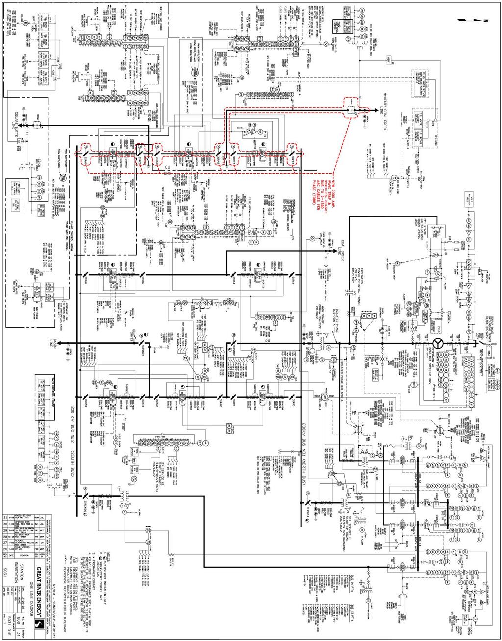
14 14
15 Exhibit A2-2 Transmission Owner One-Line Coal Creek Substation 15
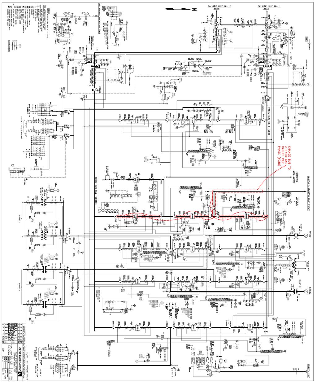
16 16
17 Exhibit A3-1 Stanton Substation - General Arrangement 17
18 18
19 Exhibit A3-2 Stanton Substation Sectional View 19
20 20
21 Exhibit A3-3 Coal Creek General Arrangement 21
22 22
23 Exhibit A3-4 Coal Creek - Sectional View 23
24 24
25 Exhibit A3-5 Coal Creek - Sectional View 25
26 26
27 Exhibit A3-6 Coal Creek - Sectional View 27
28 28
29 Exhibit A3-7 Coal Creek - Sectional View 29
30 30
31 Exhibit A4 Transmission Line Plan & Profile N/A 31
32 Exhibit A5 Facilities to be constructed by Transmission Owner (GRE) Location 1 Stand Alone Network Upgrades 2 Non-Stand Alone Network Upgrades Facilities to be Constructed by Transmission Owner None addressed under the Scope of Work for this Study Item #1 - Stanton Substation Upgrades Estimate in 2010 dollars NA $423,417* 3 Non-Stand Alone Network Upgrades 4 Interconnection Facilities Item #2 Coal Creek Substation Upgrades None addressed under the Scope of Work for this Study $88,021** * - Outages at Stanton substation will be required in phases to complete the substation work. An outage on the 230kV SHN line to Square Butte within the breaker row that includes the 230kV SV line to Coal Creek will require a 75MW Stanton Plant reduction. It may also require a Minnkota a 75MW Young Plant reduction. Spring and fall outages would be the best time to do this work and the best case would be during a scheduled unit outage at the Stanton substation. The additional cost for these plant reductions is not included in the cost estimate but will need to be considered for actual costs based on the timeframe of the outage needed. NA ** - Outages at Coal Creek substation will be required in phases to complete the substation work. An outage to the bus section connected to Filter Bank #3 may require plant reductions on unit #1 and unit #2. Spring and fall outages would be the best time to do this work and the best case would be during a scheduled unit outages at the Coal Creek Substation. The additional cost for these plant reductions is not included in the cost estimate but will need to be considered for actual costs based on the timeframe of the outage needed. 32
33 Exhibit A6-1 Detailed Cost of Stanton Substation Network Upgrades to be constructed by Transmission Owner 33
34 34
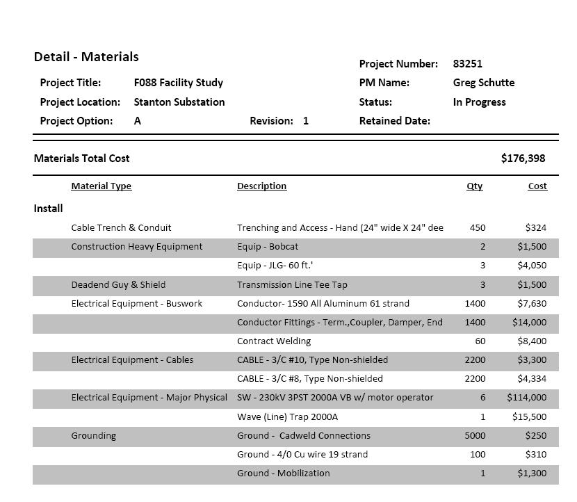
35 35
36 Exhibit A6-2 Detailed Cost of Coal Creek Substation Upgrades to be constructed by Transmission Owner 36
37 37
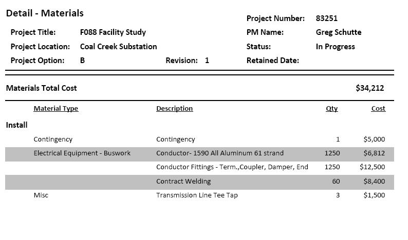
38 38
39 Exhibit A6-3 Detailed Cost of Interconnection Facilities to be constructed by Transmission Owner N/A 39
40 Exhibit A7 Facilities to be constructed by Customer Facilities constructed by the Customer are not included in this Study. 40
41 Exhibit A8 Detailed Cost of Facilities to be constructed by Customer There are no facilities to be constructed by the Customer that are covered by the scope of this study. 41
42 Exhibit A9 Facilities Subject to Transmission Owner reimbursement Location 1 Stand Alone Network Upgrades 2 Non-Stand Alone Network Upgrades Facilities to be Constructed by Transmission Owner None addressed under the Scope of Work for this Study Item #1 - Stanton Substation Upgrades Estimate in 2010 dollars NA $423,417* 3 Non-Stand Alone Network Upgrades 4 Interconnection Facilities Item #2 Coal Creek Substation Upgrades None addressed under the Scope of Work for this Study $88,021** * - Outages at Stanton substation will be required in phases to complete the substation work. An outage on the 230kV SHN line to Square Butte within the breaker row that includes the 230kV SV line to Coal Creek will require a 75MW Stanton Plant reduction. It may also require a Minnkota a 75MW Young Plant reduction. Spring and fall outages would be the best time to do this work and the best case would be during a scheduled unit outage at the Stanton substation. The additional cost for these plant reductions is not included in the cost estimate but will need to be considered for actual costs based on the timeframe of the outage needed. NA ** - Outages at Coal Creek substation will be required in phases to complete the substation work. An outage to the bus section connected to Filter Bank #3 may require plant reductions on unit #1 and unit #2. Spring and fall outages would be the best time to do this work and the best case would be during a scheduled unit outages at the Coal Creek Substation. The additional cost for these plant reductions is not included in the cost estimate but will need to be considered for actual costs based on the timeframe of the outage needed. 42
43 Exhibit A10 Contingent Facilities There are no contingency facilities addressed in this study. 43
44 Exhibit A11 Customer Milestones MISO communicated the following milestone dates for the F088 schedule. o The in-service date for the new 500kV Transmission is June 1 st, Note: 1. The Transmission Owner proposed schedule dates may not match or align with the customer requested in-service date. 44
45 Exhibit A12 Construction & Coordination Schedules The project schedule is prepared based on the normal activities and time frame required by the Transmission Owner. It may not match with the Customer requirements and inservice dates. At the time of executing the Interconnection Agreement a project schedule will be developed that will integrate with other work/projects performed by the Transmission Owner. Below is a project schedule for the Transmission Owner Facilities. Milestone Description Timeline Engineering and design May 2016 Permitting N/A Order Long Lead Material August 2016 Construction of Network Upgrades February 15 th, June 1 st, 2017 Place Network Upgrades In-service By June 1 st, 2017 Note: 1. The Transmission Owner proposed schedule dates may not match or align with the customer requested in-service date. The dates are also dependent on a signed Interconnection Agreement with the customer meeting the milestones as set forth in the Interconnection Agreement. Transmission Owner schedule dates also depend on the ability to take out the following GRE equipment 230kV SV transmission line, portions of the Stanton Substation, and portions of the Coal Creek Substation for construction during the fall or spring months. Exhibit A13 45
46 Permits, Licenses, Regulatory Approvals and Authorization Permits for the proposed Stanton and Coal Creek modifications are not expected to be required. 46
47 Exhibit A14 Interconnection and Operating Guidelines N/A 47
PLANNING GUIDE FOR SINGLE CUSTOMER SUBSTATIONS SERVED FROM TRANSMISSION LINES
 Prepared by: NIB/EOB PLANNING GUIDE FOR SINGLE CUSTOMER SUBSTATIONS SERVED FROM TRANSMISSION LINES 05503 Department: Electric T&D Section: T&D Engineering and Technical Support Approved by: G.O. Duru (GOD)
Title: YALE OFFICE OF FACILITIES PROCEDURE MANUAL Chapter: 01 - Yale Design Standard Division: Electrical Standards
 Date Description of Change Pages / Sections Modified ID 6/15/16 Updated format, division title, and removed references to other sections. - mgl44 A. Summary This section contains design criteria for the
XXXXXXXXXXX Solar (XXX) Generation Interconnection
 Generation Interconnection") Facility Study For XXXXXXXXXXX Solar (XXX) Generation Interconnection Prepared For: Randy Harlas, Substation Manager El Paso Electric Company El Paso, TX September 2010 Table of Contents 1. GENERAL...
Facility Study For XXXXXXXXXXX Solar (XXX) Generation Interconnection Prepared For: Randy Harlas, Substation Manager El Paso Electric Company El Paso, TX September 2010 Table of Contents 1. GENERAL...
Unit Price Labor. INSTALL 138KV DISCONNECT SWITCH WITH MOTOR OPERATOR AND AUXILIARY SWITCHES ON EXISTING STRUCTURE 1 ea.
 SUBSTATION B UPGRADE CONSTRUCTION MAJOR MATERIAL NOTES: Contractor to fill in line item column "Est. Qty." for items left blank. Construction Unit No. Description Est. Qty. Unit Labor 100 INSTALL 138KV
Facilities Study. For. XXXXXXXXXXXX Wind Park Interconnection Switching Station
 Facilities Study For XXXXXXXXXXXX Wind Park Interconnection Switching Station Prepared For: Randy Harlas, Substation Manager El Paso Electric Company El Paso, TX September 2010 Table of Contents CERTIFICATION...
Facility Interconnection Requirements
 Facility Interconnection Effective 1/1/2016 1. Purpose Facility Interconnection Facility Interconnection (FAC-001-2) To avoid adverse impacts on the reliability of the Bulk Electric System (BES), RPU documents
69/12KV SUBSTATION DESIGN
 69/12KV SUBSTATION DESIGN ISU SENIOR DESIGN GROUP: MAY 15-01 Matt Backes Faran Malik Ryan Jerve Bhargav Gouni Kiran Rane Sohail Suryavanshi Team Leader Communication Leader Communication Leader Key Concept
OPERATING PROCEDURE NO. 310
 OPERATING PROCEDURE NO. 310 Related Operating Procedures: 310A; 310B; 310C; 310D SUBJECT: Conditions of Service Issued: February 10, 2014 Revised: March 28, 2016 OBJECTIVE: To establish the rules, regulations
SECTION GROUNDING AND BONDING
 SECTION 16060 PART 1 GENERAL 1.01 DESCRIPTION A. Section includes requirements for an electrical grounding system, including electrodes, grounding rods, connectors, insulators, equipment grounding and
Transmission Competitive Solicitation Questions Log Question / Answer Matrix Delaney to Colorado River 2014
 No. Comment Submitted ISO Response Date Q&A Posted 1 Can the CAISO provide a line rating methodology (similar to a NERC FAC-008 standard) or include a requirement of using any The ISO does not provide
FACILITIES STUDY PID224 GENERATOR INTRCONNECTION
 TRANSMISSION LINE & SUBSTATION PROJECTS COMPANY : EAI CUSTOMER: PID 224 FACILITIES STUDY EJO # F4PPAR0462 PID224 GENERATOR INTRCONNECTION Revision: 2 Rev Issue Date Description of Revision Prepared By
COUNTY OF RIVERSIDE BUILDING AND SAFETY DEPARTMENT PHOTOVOLTAIC PERMITTING GUIDELINES
 COUNTY OF RIVERSIDE BUILDING AND SAFETY DEPARTMENT Mike Lara Building Official PHOTOVOLTAIC PERMITTING GUIDELINES PLANS AND PERMITS In order to minimize installation problems, plans must be provided that
Information Document Service Proposals and Cost Estimating ID # R
 Information Documents are not authoritative. Information Documents are for information purposes only and are intended to provide guidance. In the event of any discrepancy between an Information Document
Standard of Practice - Campus Electrical Distribution System
 A26.3 Standard of Practice - Campus Electrical Distribution System NOTE: Significant revisions or additions to the previous standards are highlighted in italics. GENERAL Designers shall verify that all
DIVISION 26 ELECTRICAL Electrical Power Conductors and Cables
 PART 1 - GENERAL 1.01 DESIGN REQUIREMENTS A. Scope: Power Conductors and Cables in this section are defined as system voltages above 120V and less than 600V. B. System Voltages Three Phase and Single Phase:
Electrical Systems: Theory and Operation
 Turf Equipment Management Program Turf Equipment Technician Certificate Study Guide Electrical Systems: Theory and Operation Table of Contents Turf Equipment Technician Exam Background... 1 Exam Structure
Distribution Information Exchange Code
 Distribution Information Exchange Code Version 5.1 Approved September 2007 Comments to this document can be forwarded to: The RSA Grid Code Secretariat Attention: Mr. Bernard Magoro Eskom, Transmission
Inspection Guide for PV Systems in One- and Two- Family Dwellings (For Rooftop Photovoltaic Systems meeting the Standard Plan)
") TOOLKIT DOCUMENT #7 Inspection Guide for PV Systems in One- and Two- Family Dwellings (For Rooftop Photovoltaic Systems meeting the Standard Plan) This document has two sections. Neither section is all-inclusive
TOOLKIT DOCUMENT #7 Inspection Guide for PV Systems in One- and Two- Family Dwellings (For Rooftop Photovoltaic Systems meeting the Standard Plan) This document has two sections. Neither section is all-inclusive
The Narragansett Electric Company d/b/a National Grid. and Clear River Energy LLC. (Burrillville Interconnection Project) RIPUC Dkt. No.
 RIPUC Dkt. No.") d/b/a National Grid and Clear River Energy LLC (Burrillville Interconnection Project) RIPUC Dkt. No. Testimony of David J. Beron, P.E., P.M.P. November, 0 0-v R.I.P.U.C. Dkt. No. 0 0 INTRODUCTION Q. Please
d/b/a National Grid and Clear River Energy LLC (Burrillville Interconnection Project) RIPUC Dkt. No. Testimony of David J. Beron, P.E., P.M.P. November, 0 0-v R.I.P.U.C. Dkt. No. 0 0 INTRODUCTION Q. Please
POTOMAC ELECTRIC POWER COMPANY
 POTOMAC ELECTRIC POWER COMPANY FERC Form 715 (Part 4) - Transmission Planning Study Guidelines Transmission Reliability Guidelines 1. General Overview The reliability guidelines used to plan the transmission
A. All materials shall be tested and listed by an OSHA approved Nationally Recognized Testing Laboratory (NRTL).
.") 16450 GROUNDING ************************************************************************************************************* SPECIFIER: CSI MasterFormat 2004 number: 26 05 26 An optional keynote to the
16450 GROUNDING ************************************************************************************************************* SPECIFIER: CSI MasterFormat 2004 number: 26 05 26 An optional keynote to the
Introduction to Substation Design TADP 542
 Introduction to Substation Design TADP 542 Design Principles- General Framework Instructor: Richard Snell Transmission & Distribution Program Module 2 Outline Presentation 1: General Framework Presentation
Clean Line Energy Partners
 Clean Line Energy Partners 2012 Transmission investment is required to connect the best wind resources to load centers Clean Line projects Rock Island CA Centennial West Grain Belt Express Plains & Eastern
XXXX. Bremner Trio Small Hydro Project. Interconnection System Impact Study
 XXXX Bremner Trio Small Hydro Project Report No. August 2010 British Columbia Hydro and Power Authority British Columbia Hydro and Power Authority 2010. All rights reserved.. DISCLAIMER OF WARRANTY, LIMITATION
BUSWAY LOW VOLTAGE (POW-R-WAY III) SECTION SECTION 16466
 SECTION SECTION 16466") BUSWAY LOW VOLTAGE (POW-R-WAY III) PART 1 GENERAL 1.01 1.02 SCOPE The Contractor shall furnish and install the busway system including all necessary fittings, hangers and accessories as specified herein
BUSWAY LOW VOLTAGE (POW-R-WAY III) PART 1 GENERAL 1.01 1.02 SCOPE The Contractor shall furnish and install the busway system including all necessary fittings, hangers and accessories as specified herein
DOWNTOWN UNDERGROUND NETWORK SECONDARY SERVICES GUIDELINES
 Guidelines effective March 5, 2007 NES is committed to providing safe, reliable electric service at a reasonable price for all of our customers. These guidelines offer direction for activities relating
DUQUESNE LIGHT COMPANY TRANSMISSION PLANNING CRITERIA
 DUQUESNE LIGHT COMPANY TRANSMISSION PLANNING CRITERIA Transmission Planning Criteria Updated: March Compiled: September 2007 Compiled from: s Comprehensive Transmission Reliability Plan, July 2005 s Strategic
A SUBSTATION CONCEPT FOR CHANGEABLE LOAD CONDITIONS
 A SUBSTATION CONCEPT FOR CHANGEABLE LOAD CONDITIONS Willy LORD SwedPower AB Sweden willy.lord@swedpower.com Lennart AHNLUND Vattenfall Eldistribution AB Sweden B. WALLBING-LÖVGREN Vattenfall Eldistribution
TRC Solutions. Cost and Feasibility Analysis of a Third Converter Station for the Champlain Hudson Power Express Project
 TRC Solutions Cost and Feasibility Analysis of a Third Converter Station for the Champlain Hudson Power Express Project October 2013 Table of Contents: I. Executive Summary II. Cost Estimate and Physical
Summary details for SPC TSR # and MH TSR # are shown in Tables ES.1 and ES.2: Service Requested
 Executive Summary Firm point to point transmission service has been requested by Transmission Service Request (TSR) #80439788, under the SaskPower Open Access Transmission Tariff (OATT). The purpose of
BULLETIN LICENSED ELECTRICAL CONTRACTORS. SaskPower Electrical Inspections. June 13, Item #1 Arc-Fault Receptacles, CEC Rule (f)
") SaskPower Electrical Inspections BULLETIN 01-2014 June 13, 2014 TO: LICENSED ELECTRICAL CONTRACTORS SUBJECT: GENERAL BULLETIN Item #1 Arc-Fault Receptacles, CEC Rule 26-722(f) For the purposes of this
SaskPower Electrical Inspections BULLETIN 01-2014 June 13, 2014 TO: LICENSED ELECTRICAL CONTRACTORS SUBJECT: GENERAL BULLETIN Item #1 Arc-Fault Receptacles, CEC Rule 26-722(f) For the purposes of this
Summary details for SPC TSR # and MH TSR # are shown in Tables ES.1 and ES.2: IFHS MH MW, firm :00:00 CS
 Executive Summary Firm point to point transmission service has been requested by Transmission Service Request (TSR) #80487374, under the SaskPower Open Access Transmission Tariff (OATT). The purpose of
Requirements for Transmission System Interconnections to Generation, Transmission and End-User Facilities Revised June 10, 2014
 Requirements for Transmission System Interconnections to Generation, Transmission and End-User Facilities Revised June 10, 2014 1040 O Street, P.O. Box 80869 p: 402.475.4211 Lincoln, NE 68501-0869 www.les.com
XXXXX. Bremner Trio Small Hydro Project. Interconnection Facilities Study and Project Plan
 XXXXX Bremner Trio Small Hydro Project Interconnection Facilities Study and Project Plan June 25, 2011 British Columbia Hydro and Power Authority British Columbia Hydro and Power Authority 2011. All rights
COST ALLOCATION POLICY FOR VICTORIAN TERMINAL STATIONS NEGOTIATED TRANSMISSION SERVICES
 COST ALLOCATION POLICY FOR VICTORIAN TERMINAL STATIONS NEGOTIATED PREPARED BY: Network Development VERSION: 2.0 RELEASE DATE: 30 May 2012 Version Release History Version Date By Changes 1.0 6 Oct 11 Transmission
Standard TPL Transmission System Planning Performance Requirements
 A. Introduction 1. Title: Transmission System Planning Performance Requirements 2. Number: TPL-001-4 3. Purpose: Establish Transmission system planning performance requirements within the planning horizon
Standard Development Timeline
 Standard Development Timeline This section is maintained by the drafting team during the development of the standard and will be removed when the standard is adopted by the NERC Board of Trustees (Board).
SECTION SUBSTATION BUS ASSEMBLIES ERGLE SUBSTATION
 SECTION 16-372 SUBSTATION BUS ASSEMBLIES ERGLE SUBSTATION 1. GENERAL SPECIFICATIONS The work of this Section includes furnishing all labor, equipment, materials (unless specifically identified as Owner-furnished)
Proposals and Process 2017 National Electrical Code
 Proposals and Process 2017 National Electrical Code for Solar America Board for Codes and Standards Stakeholder Meeting; October 23, 2014 Ward Bower Ward Bower Innovations LLC Introduction The New NFPA
BULLETIN SUBJECT: GENERAL BULLETIN, 2015 SASK INTERPRETATIONS CORRECTIONS, AND ELECTRIC SERVICE REQUIREMENT CHANGES OR ADDITIONS
 SaskPower Electrical Inspections BULLETIN 01-2017 February 15, 2017 TO: LICENSED ELECTRICAL CONTRACTORS ELECTRICAL CONSULTANTS AND ENGINEERS SUBJECT: GENERAL BULLETIN, 2015 SASK INTERPRETATIONS CORRECTIONS,
Engineering Data for Copper and Aluminum Conductor Electrical Cables
 2018 Edition Engineering Data for Copper and Aluminum Conductor Electrical Cables THE OKONITE COMPANY Okonite Cables...A higher Standard! The Okonite Company, 2018 Okonite Cables Table of Contents SECTION
SECTION BASIC ELECTRICAL REQUIREMENTS
 PART 1 - GENERAL 1.1 RELATED DOCUMENTS A. Drawings and general provisions of Contract, including General and Supplementary Conditions, apply to work of this section. 1.2 SUMMARY A. This section specifies
The Canadian Electrical Code (Saskatchewan Amendments) Regulations, 1999
 Regulations, 1999") CANADIAN ELECTRICAL CODE 1 The Canadian Electrical Code (Saskatchewan Amendments) Regulations, 1999 Repealed by Chapter E-6.3 Reg 8 (effective June 24, 2003). Formerly Chapter E-6.3 Reg 6 (effective March
CANADIAN ELECTRICAL CODE 1 The Canadian Electrical Code (Saskatchewan Amendments) Regulations, 1999 Repealed by Chapter E-6.3 Reg 8 (effective June 24, 2003). Formerly Chapter E-6.3 Reg 6 (effective March
Information Document Protection System Information ID# R
 Information Documents are for information purposes only and are intended to provide guidance. In the event of any discrepancy between the Information Document and the related authoritative document(s)
South Fork RFP LIPA Board of Trustees REV Committee Briefing. September 21, 2016
 South Fork RFP LIPA Board of Trustees REV Committee Briefing September 21, 2016 Latest Developments A portfolio of projects is recommended to meet the needs of the South Fork, which includes the South
SERVICE ENTRANCES. OPPD S Electrical Service Designer (ESD) shall designate the Point Of Entrance.
 shall designate the Point Of Entrance.") SERVICE ENTRANCES 3.01 POINT OF ENTRANCE General Service The customer, or the customer s electrician, should provide OPPD with a site plan, load schedule, and voltage requirements when requesting service.
SERVICE ENTRANCES 3.01 POINT OF ENTRANCE General Service The customer, or the customer s electrician, should provide OPPD with a site plan, load schedule, and voltage requirements when requesting service.
Distributed Generation. Technical Requirements and Interconnection Agreements
 Distributed Generation Technical Requirements and Interconnection Agreements February 2005 Table of Contents Section 1: Interconnection Process for Distributed Generation Systems (17 pages) Section 2:
(Condensed from National Electric Code)
") WIRING, SPECIFICATIONS, INSPECTION, AND METER INSTALLATION PROCEDURES FOR RESIDENTIAL CUSTOMERS SERVED BY SOUTHWEST ARKANSAS ELECTRIC COOPERATIVE CORPORATION Effective April 1, 1974 Revised February 3,
WIRING, SPECIFICATIONS, INSPECTION, AND METER INSTALLATION PROCEDURES FOR RESIDENTIAL CUSTOMERS SERVED BY SOUTHWEST ARKANSAS ELECTRIC COOPERATIVE CORPORATION Effective April 1, 1974 Revised February 3,
DISTRIBUTION SYSTEM PLANNING TUTORIAL. MN Power Systems Conference November 6, 2014
 DISTRIBUTION SYSTEM PLANNING TUTORIAL MN Power Systems Conference November 6, 2014 CONNEXUS ENERGY 128,000 customers 1,000 sq. miles territory 44 substations 8,800 miles distribution 12.47 kv Wholesale
AT&T January, 2012 Revised April, GENERAL... C Introduction... C-1
 INSTALLER SKILL LEVEL ASSESSMENT Section C, ATT-TP-76300 AT&T January, 2012 Revised April, 2017 SECTION C-- INSTALLER SKILL LEVEL ASSESSMENT CONTENTS PAGE 1. GENERAL... C-1 1.1. Introduction... C-1 2.
SECTION 16496A MTS MANUAL TRANSFER SWITCH (MANUAL CONTROL ONLY) Note to Spec Writer: { } Denotes EATON Feature reference number
 Note to Spec Writer: { } Denotes EATON Feature reference number") MTS MANUAL TRANSFER SWITCH (MANUAL CONTROL ONLY) Note to Spec Writer: { } Denotes EATON Feature reference number PART 1 GENERAL 01 02 03 04 SCOPE Furnish and install Manual Transfer Switches (MTS) and
MTS MANUAL TRANSFER SWITCH (MANUAL CONTROL ONLY) Note to Spec Writer: { } Denotes EATON Feature reference number PART 1 GENERAL 01 02 03 04 SCOPE Furnish and install Manual Transfer Switches (MTS) and
Standard EOP System Restoration from Blackstart Resources
 A. Introduction 1. Title: System Restoration from Blackstart Resources 2. Number: EOP-005-2 3. Purpose: Ensure plans, Facilities, and personnel are prepared to enable System restoration from Blackstart
Revisions for the 2011 National Electrical Code - Part 2
 PDHonline Course E356 (3 PDH) Revisions for the 2011 National Electrical Code - Part 2 Instructor: Patrick Ouillette 2012 PDH Online PDH Center 5272 Meadow Estates Drive Fairfax, VA 22030-6658 Phone &
Section ARMORED MEDIUM VOLTAGE CABLES SHIELDED 3 CONDUCTOR POWER CABLE - INTERLOCKED ARMOR
 PART 1 - GENERAL Section 26 05 15 SHIELDED 3 CONDUCTOR POWER CABLE - INTERLOCKED ARMOR 1.1 Cable shall be 15 kv, shielded, three conductor with ground, stranded copper, with continuously welded and corrugated
SECTION GROUNDING AND BONDING FOR ELECTRONIC SAFETY AND SECURITY
 PART 1 - GENERAL 1.1 DESCRIPTION SECTION 28 05 26 GROUNDING AND BONDING FOR ELECTRONIC SAFETY AND SECURITY SPEC WRITER NOTE: Delete // // if not applicable to project. Also delete any other item or paragraph
Standard PRC-002-NPCC-01 Disturbance Monitoring
 A. Introduction 1. Title: Disturbance Monitoring 2. Number: PRC-002-NPCC-01 3. Purpose: Ensure that adequate disturbance data is available to facilitate Bulk Electric System event analyses. All references
ELECTRICAL INSPECTION BULLETIN (Effective )
") ELECTRICAL INSPECTION BULLETIN (Effective 2009-02-01) Rule 36-000 Customer Owned High Voltage Installations With the increase in customer own high voltage equipment there appears to be confusion over which
ELECTRICAL INSPECTION BULLETIN (Effective 2009-02-01) Rule 36-000 Customer Owned High Voltage Installations With the increase in customer own high voltage equipment there appears to be confusion over which
NORTHWESTERN UNIVERSITY PROJECT NAME JOB # ISSUED: 03/29/2017
 SECTION 26 0526 - GROUNDING AND BONDING FOR ELECTRICAL SYSTEMS PART 1 - GENERAL 1.1 RELATED DOCUMENTS A. Drawings and general provisions of the Contract, including General and Supplementary Conditions
Benchmarking and Control Indicators for Electrical Substation Projects
 Benchmarking and Control Indicators for Electrical Substation Projects Submitted by: Justin R. Nettesheim A thesis submitted in partial fulfillment of the requirements for the degree of Master of Civil
SECTION AUTOMATIC TRANSFER SWITCH
 SECTION 26 36 23 AUTOMATIC TRANSFER SWITCH PART 1: GENERAL 1.01 SCOPE A. Furnish all labor, materials, equipment and appurtenances, install and test electrically operated, automatic transfer switch (ATS)
For the 2008 Code, the minimum clear distances were revised to reflect an accurate metric conversion (also known as a soft conversion).
.") II. 600 Volts, Nominal, or Less 110.26 Spaces About Electrical Equipment. Sufficient access and working space shall be provided and maintained about all electrical equipment to permit ready and safe operation
II. 600 Volts, Nominal, or Less 110.26 Spaces About Electrical Equipment. Sufficient access and working space shall be provided and maintained about all electrical equipment to permit ready and safe operation
Work Portfolio. Powered by People
 Work Portfolio Powered by People Teck Teck is a diversified resource company committed to responsible mining and mineral development with business units focused on copper, steelmaking coal, zinc, and energy.
Unit Substation Transformer Construction Checklist (under 500 kva)
") Unit Substation Transformer Checklist (under 500 kva) Building: Location: Submittal / Approvals Submittal. The above equipment and systems integral to them are complete and ready for functional testing.
Unit Substation Transformer Checklist (under 500 kva) Building: Location: Submittal / Approvals Submittal. The above equipment and systems integral to them are complete and ready for functional testing.
WIRING RULES AND REGULATIONS OF TOMBIGBEE ELECTRIC POWER ASSOCIATION
 WIRING RULES AND REGULATIONS OF TOMBIGBEE ELECTRIC POWER ASSOCIATION The following rules and information are issued to make it possible for anyone engaged in electrical wiring or installation of electrical
Requirements For Generation and Transmission Interconnections
 Requirements For Generation and Transmission Interconnections Table of Contents 1.0 INTRODUCTION... 1 2.0 INTERCONNECTION POLICY... 2 3.0 STANDARD INTERCONNECTION PROCESS... 3 3.1 ASSUMPTIONS... 3 3.2
SPECIFICATIONS FOR NASSAU SUBSTATION COMBINED METERING UNIT REPLACEMENTS ENGINEERING AND CONSTRUCTION SERVICES SUBSTATION PROJECT DESIGN 20410
 SPECIFICATIONS FOR NASSAU SUBSTATION COMBINED METERING UNIT REPLACEMENTS ENGINEERING AND CONSTRUCTION SERVICES SUBSTATION PROJECT DESIGN 20410 SECTION VII - TECHNICAL SPECIFICATIONS - SPECIFIC INSTRUCTIONS
POWERTECH LABS INC. CONNECTABILITY TESTING OF COPPER AND ALUMINUM WIRING, PHASE 2: Current Cycling Tests Mechanical Connectors PROJECT PL-00236
 Management System Registered to ISO 9001/14001 12388-88 th Avenue Tel: (604)590-7500 Surrey, British Columbia Fax: (604)590-5347 Canada V3W 7R7 www.powertechlabs.com POWERTECH LABS INC. CONNECTABILITY
September 9, The documents submitted with this filing consist of this letter of transmittal and all attachments hereto, and the Agreement.
 Regulation James A. Cuillier Director FERC Rates & Regulation September 9, 2014 Ms. Kimberly D. Bose, Secretary Federal Energy Regulatory Commission 888 First Street, N.E. Washington, DC 20426 Dear Ms.
UNDERGROUND SERVICES SECONDARY
 Reference UNDERGROUND SERVICES SECONDARY Underground services secondary... U- 1 General requirements for underground service... U- 2 Name of parts for underground service... U- 3 Conduit layouts... U-
Audit Approach to FAC Transmission Vegetation Management FRCC Webinar
 Audit Approach to FAC-003-2 Transmission Vegetation Management FRCC Webinar September 2013 Ground Rules All participants will be muted upon sign-on Please keep your phone on mute unless asking a question
Minimum Transmission Design Standards f or Competitive Upgrades Rev 2
 Minimum Transmission Design Standards f or Competitive Upgrades Rev 2 December, 2016 Minimum Design Standards Task Force Revision History Date or Version Number 12/17/2014 Revision IR Author Change Description
2017 NEC Changes for Renewable Energy Systems Session one by Christopher LaForge
 2017 NEC Changes for Renewable Energy Systems Session one 2017 by Christopher LaForge Christopher LaForge IREC Certified Master Trainer NABCEP Certified Photovoltaic Installation Professional 30 years
Queue Management. A look at queue reform and. Jennifer Heintz and Janet Wheeler June 12, 2012
 Queue Management A look at queue reform and the queue process Jennifer Heintz and Janet Wheeler June 12, 2012 1a What is a queue? The interconnection queue (queue) refers to the process of getting a new
Lesson Learned Loss of Wind Turbines due to Transient Voltage Disturbances on the Bulk Transmission System
 Lesson Learned Loss of Wind Turbines due to Transient Voltage Disturbances on the Bulk Transmission System Primary Interest Groups Balancing Authorities (BAs) Transmission Operators (TOPs) Generator Operators
Incremental Black Start RFP Response Template & General Information
 Revision 2: 7/28/2015 Incremental Black Start RFP Response Template & General Information Overview This document is divided into three sections: Section 1: An incremental RFP response template Section
Power Electronics, Inc. Packaged Equipment Center Standard Construction and Design Features
 DESIGN CRITERIA FOR STANDARD CONSTRUCTION: These standard design elements of the P.E.I. Power Equipment Center are utilized to meet the following design criteria per ASCE 7-05 as adopted by the IBC (International
ACCR. More Amps. More Confidence. Glenmar E. Cambri, REE Senior Applications Engineer
 TM ACCR More Amps More Confidence Glenmar E. Cambri, REE Senior Applications Engineer What is 3M ACCR? A high voltage, overhead transmission conductor designed as a drop-in replacement for ACSR and other
Basic Requirements for Residential Electrical Installations
 Basic Requirements for Residential Electrical Installations Wayne County Building Department 428 West Liberty Street Wooster, Ohio 44691 Phone: 330-287-5525 Fax: 330-287-5649 This brochure is intended
Detailed Requirements Document (DRD) Rail Engineering Advanced Technician Level 4 Electrification Knowledge & Skills Content
 Rail Engineering Advanced Technician Level 4 Electrification Knowledge & Skills Content") Detailed Requirements Document (DRD) Rail Engineering Advanced Technician Level 4 Electrification Knowledge & Skills Content Purpose The purpose of this Detailed Requirements Document (DRD) is to provide
Detailed Requirements Document (DRD) Rail Engineering Advanced Technician Level 4 Electrification Knowledge & Skills Content Purpose The purpose of this Detailed Requirements Document (DRD) is to provide
2003 International Residential Code ELECTRICAL PROVISIONS ONLY October 2005 EDITORIAL CHANGES SEVENTH PRINTING
 2003 International Residential Code ELECTRICAL PROVISIONS ONLY October 2005 EDITORIAL CHANGES SEVENTH PRINTING E3305.3: now reads The space equal to the width and depth of the panelboard and extending
Business Practice. Contents
 Business Practice Department: External Affairs Document No: BP-1001 v1.0 Title: TRANSMISSION RELATED STATION POWER USE AT SUBSTATIONS Issue Date: 11-01-2010 Previous Date: 09-05-2017 Contents 1 PURPOSE...
Building Codes in Effect: 2010 California Building, Residential, Fire, Energy and Electrical Codes, including Article 690.
 AGUA CALIENTE BAND OF CAHUILLA INDIANS A SOVEREIGN TRIBAL GOVERNMENT Planning & Development Department Building and Safety Division 5401 Dinah Shore Drive Palm Springs, CA 92264 (760) 669-6800 RESIDENTIAL
Cluster Study Process
 Cluster Study Process This presentation is a tool to supplement the FERC approved Generator Procedures (GIP) found in Attachment I of PG&E s Wholesale Distribution Tariff (WDT) and Appendix Y of CAISO
CONSOLIDATED EDISON COMPANY OF NEW YORK, INC Van Dam Street Long Island City, NY ELECTRIC METER SHOP DEPARTMENT
 CONSOLIDATED EDISON COMPANY OF NEW YORK, INC. 48-05 Van Dam Street Long Island City, NY 11101 ELECTRIC METER SHOP DEPARTMENT METER ENGINEERING SPECIFICATION MES-350 REVISION 3 June 2016 EFFECTIVE DATE
WITH THE TITLE 24. replacement. story. stories, etc. R disconnects. to, PV. unit and any. supporting frame. conditions. greater than the main
 CITY OF CYPRESS Building Division 5275 Orange Avenue, Cypress, California 906300 714-229-6730 buildingpermits@ @ci.cypress.ca.us RESIDENTIAL PHOTOVOLTAIC SYSEMS ALL WORK SHALL REQUIRE COMPLIANCE WITH THE
CONSTRUCTION SPECIFICATION FOR INSTALLATION OF CABLE
 ONTARIO PROVINCIAL STANDARD SPECIFICATION OPSS.PROV 604 NOVEMBER 2017 CONSTRUCTION SPECIFICATION FOR INSTALLATION OF CABLE TABLE OF CONTENTS 604.01 SCOPE 604.02 REFERENCES 604.03 DEFINITIONS - Not Used
SECTION LOW-VOLTAGE SWITCHGEAR
 PART 1 - GENERAL 1.1 DESCRIPTION SECTION 26 23 00 LOW-VOLTAGE SWITCHGEAR SPEC WRITER NOTE: This specification is not for general use. Use Section 26 24 13, DISTRIBUTION SWITCHBOARDS for most applications.
Session 9: Photovoltaic System Case Studies And Electric Distribution Planning for DER October 21, 2015 Santiago, Chile
 Session 9: Photovoltaic System Case Studies And Electric Distribution Planning for DER October 21, 2015 Santiago, Chile Michael Coddington National Renewable Energy Laboratory Golden, Colorado, U.S.A.
SCHEDULE 12 Transmission Enhancement Charges. Establishment of Transmission Enhancement Charges.
 SCHEDULE 12 Transmission Enhancement Charges (a) Establishment of Transmission Enhancement Charges. (i) Establishment of Transmission Enhancement Charges by Transmission Owners and Entities That Will Become
Galvanic and Stray Current Corrosion
 Chapter 5 Galvanic and Stray Current Corrosion MElec-Ch5-1 Overview Galvanic Corrosion Understanding Galvanic Corrosion Controlling Galvanic Corrosion Stray Current Corrosion Understanding Stray Current
1. Telecommunications mounting elements. 2. Backboards. 3. Telecommunications equipment racks and cabinets. 4. Grounding.
 ALLIANT ENERGY CENTER PAVILIONS Project No. 2013 027 SECTION 27 11 00 - PART 1 - GENERAL 1.1 RELATED DOCUMENTS A. Drawings and general provisions of the Contract, including General and Supplementary Conditions
Small Generator Interconnection Procedures (SGIP) Customer Guide
 Customer Guide") Customer Guide SCE&G utilizes a FERC mandated and approved process, known as the Small Generator Interconnection Procedure (SGIP), to evaluate the interconnection of small generators to the SCE&G transmission
Customer Guide SCE&G utilizes a FERC mandated and approved process, known as the Small Generator Interconnection Procedure (SGIP), to evaluate the interconnection of small generators to the SCE&G transmission
TEMPORARY METER POLE INSTALLATION
 TEMPARY METER POLE INSTALLATION MEMBER PROVIDED Location to be made by REMC within 50' of our transformer or existing service Temporary pole to be properly braced 24" 3 wire weatherhead (located 24" from
SECTION HIGHWAY GRADE CROSSING WARNING SYSTEMS
 SECTION 18700 PART 1 - GENERAL 1.01 DESCRIPTION A. Section includes requirements for highway grade crossing warning systems. B. Where shown on the Contract Drawings or as required to accommodate associated
ELECTRICAL BULLETIN
 PO Box 697 Halifax, Nova Scotia B3J 2T8 Labour and Advanced Education ELECTRICAL BULLETIN 2012-01 From: David MacLeod,C.E.I.,P.Eng. Pg 1 of 8 Provincial Chief Electrical Inspector Date : March 1, 2012
Member Service Electric Wiring Guidelines
 Member Service Electric Wiring Guidelines Table of Contents A. Definitions... 2 B. Member Service Wiring Guidelines... 2 C: Meter located on the house from an underground source - pad transformer or j-box....
Low Voltage Switchgear Construction Checklist (under 500 kva)
") Low Voltage Switchgear Checklist (under 500 kva) Project: Building: Location: Submittal / Approvals Submittal. The above equipment and systems integral to them are complete and ready for functional testing.
Low Voltage Switchgear Checklist (under 500 kva) Project: Building: Location: Submittal / Approvals Submittal. The above equipment and systems integral to them are complete and ready for functional testing.
Applying For New or Revised Electric Service. ComEd is happy to assist you in initiating new or revised electric service to your location.
 ComEd Applying For New or Revised Electric Service ear Customer: ComEd is happy to assist you in initiating new or revised electric service to your location. ComEd must be notified prior to any new construction,