PHOTOVOLTAIC. Total integration system for traditional photovoltaic panels. Installation manual V 11.0 SMABTP
|
|
|
- Darcy Bond
- 6 years ago
- Views:
Transcription


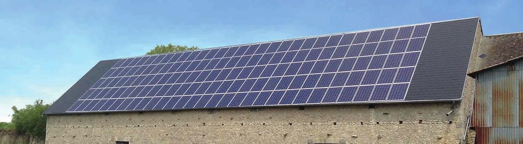
1 PHOTOVOLTAIC GSE IN-ROOF SYSTEM Total integration system for traditional photovoltaic panels Installation manual V 11.0 SMABTP BT / MARS MARS 2017 EUROPEAN LEADER IN PHOTOVOLTAIC INTEGRATION SYSTEMS

2 2
3 Contents 1 Kit presentation Presentation of the GSE In-Roof System Contents of the kit PORTRAIT GSE Plate LANDSCAPE GSE Plate Tools required 8 2 Building site preparation Climate impact Photovoltaic field setting up Portrait mounting Landscape mounting 11 3 Implementation Preparation of the roof covering Positioning of the mounting battens Low sealing strip installation GSE Plates installation Side flashings installation PV modules installation Ridge flashings installation Specific case : PV field with inner/outer brackets Connection to the roof covering 29 4 Maintenance and servicing Verification Module replacement 30 5 Assistance and contact Training session Technical assistance 31 6 Certifications and warranties Technical assessments Fire Test 31 GSE IN-ROOF SYSTEM 3
, on new buildings or buildings being renovated.")
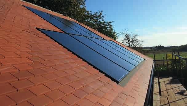
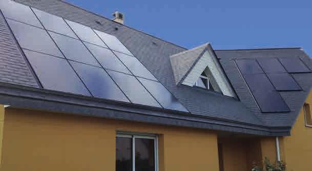
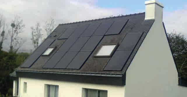
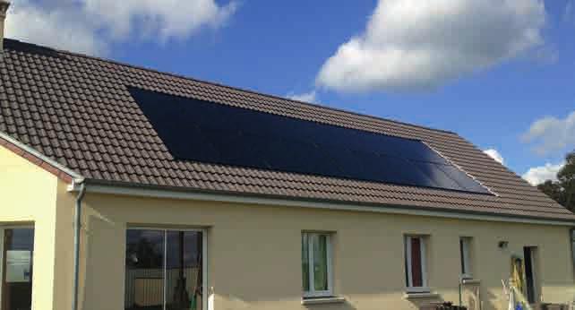
4 1. Kit presentation 1.1 GSE In-Roof System GSE In-Roof System enables modules installation on every type of roof covering (curved tiles, interlocking, flat, slates), on new buildings or buildings being renovated. The system may be installed in portrait or landscape format, with a specific mounting plate for each format, on both small installations (less than 3 kwp) and large roofs (ie specific manual). GSE In-Roof System may be installed on wooden frameworks and mounted on a batten adapted to climatic conditions and framework structure. It can be mounted on slopes between 12 and 50. GSE In-Roof System is guaranteed for 10 years by the ten-year manufacturer s warranty from SMABTP. The system does not require much maintenance, except regular cleaning of the solar panels to guarantee an optimum production. Complementary manuals available : v.atec In-Roof GSE INTEGRATION Kit. Large Roof In-Roof GSE INTEGRATION Kit. Roof-Windows In-Roof GSE INTEGRATION Kit. 4


5 1. Kit presentation 1.2 Contents of the kit MOUNTING PLATES Portrait GSE Plate Landscape GSE Plate MOUNTING BRACKETS Wood self-drilling screw 6,5 x 60 Cellular EPDM square seal Simple fixing brackets Double fixing brackets Installation s edge wedges (L/R) FLASHINGS Flashing hook Side flashing OPTION 1 OPTION 2 Central flashing Attach angle Aluminium pop rivet Ridge junction Angle flashing Sheet of zinc WATERPROOFING GSE Rooflex or eq. Sheet of zinc Lead tape Precompressed seal HPV roof underlayment GSE IN-ROOF SYSTEM 5

 (pre-drilling 10mm) Bracket fixation point (4 brackets) (pre-drilling 10mm) Conçu par")
 Plate")
 Bracket fixation point (4 brackets) (pre-drilling 10mm) REF.")

6 5 C 1. Kit Presentation Flowguide 1.3 PORTRAIT GSE Plate PV panel support pads Upper PV panel support D Graduated overlapping zone B Flowguide PV panel support pads A C Plate fixation point (without pre-drilling) Plate fixation point (pre-drilling 10mm) Bracket fixation point (6 brackets) (pre-drilling 10mm) Bracket fixation point (4 brackets) (pre-drilling 10mm) Conçu par Vérifié par Approuvé par Date Date F. PRUDHOMME 08/09/2016 B DOC-NOT-IR 2 Modification 1 1 Plate fixation point (without pre-drilling) Plate fixation point (pre-drilling 10mm) Portrait plate references Module sizes Bracket fixation point (6 brackets) (pre-drilling 10mm) Bracket fixation point (4 brackets) (pre-drilling 10mm) REF / 1046 PV PANELS TOLERANCE HEIGHT (mm) WIDTH (mm) A Conçu par Vérifié par Approuvé par Date Date F. PRUDHOMME 08/09/ / DOC-NOT-IR / 1082 Modification 1580 / Feuille 1 / / Overlapping area graduation 1640 / / Height tolerance Width tolerance 6
 Plate fixation point (pre-drilling")
 WIDTH (mm) Conçu par Vérifié par Approuvé par Date Date F.")

7 C Flowguide 1. Kit Presentation PV panel support pads 51.4 LANDSCAPE 4 GSE Plate Upper PV panel support D B Flow guide C PV panel support pads A Plate fixation point (without pre-drilling) Plate fixation point (pre-drilling 10mm) Bracket fixation point (6 brackets) (pre-drilling 10mm) Bracket fixation point (4 brackets) B (pre-drilling 10mm) Landscape plate references Module sizes 6 5 Conçu par Vérifié par Approuvé par Date F. PRUDHOMME DOC-NOT-IR PV PANELS TOLERANCE REF. HEIGHT (mm) WIDTH (mm) Conçu par Vérifié par Approuvé par Date Date F. PRUDHOMME 08/09/ / A / / / DOC-NOT-IR Modification 1 Feuille 2 / / / / / / Overlapping area graduation 1686 / / Height tolerance Width tolerance GSE IN-ROOF SYSTEM 7


8 1. Kit Presentation 1.5 Tools required CHALK LINE REEL HAMMER SCREWDRIVER Adjustable torque necessary PLATE SHEAR DRILL BITS WOOD AND METAL DRILL BIT Ø 10MM POP RIVET PLIER HEX BIT Ø 8MM MEASURING TAPE WHITE MARKER PENCIL ASSEMBLY VIDEO PLEASE FIND ALL OUR ASSEMBLY VIDEOS ON YOUTUBE : GSE IN-ROOF SYSTEM GSE AIR'SYSTEM 8
 and the PV field settings according to current regulations (Eurocodes and règles NV65).")

9 2. Building site preparation The installing technician must proceed to a measurement work beforehand, which will enable him to guarantee the durability and performance of the PV field installed. He must take into account the climate impact on the project site (ie. wind and snow 1 ) and the PV field settings according to current regulations (Eurocodes and règles NV65). These data will help determine the number of brackets and appropriate lathing (figures in sections 2.3 and 2.4 are given as example). The chosen thickness must be adapted to the roof battens one to guarantee the PV field edges flashings waterproofing. 2.1 Climat Impact Maps of the wind zones in the UK: WIND 2.2 Photovoltaic field setting up The PV field integration is impacting on the wind load value whether it is in the center, on the edge or the corner. The most adverse setting-up should be taken into account. RIDGE RIDGE CORNER CORNER CORNER EDGE CORNER EDGE CENTER EDGE EDGE CENTER EDGE CORNER EDGE CORNER CORNER EDGE CORNER GUTTER GUTTER Two-sloped roof One sloped roof 1 The earthquake resistance of the GSE In-Roof System being validated on the whole European territory, this criterion is not to be taken into account. GSE IN-ROOF SYSTEM 9

 10")
10 2. Building site preparation 2.3 Portrait mounting Choosing the number of brackets Lathing section (two-sloped roof Slopes : 12 à 50 - Terrain category : IIIa) 10

 GSE IN-ROOF")
11 2. Building site preparation 2.4 Landscape mounting Choosing the number of brackets Lathing section (two-sloped roof Slopes : 12 à 50 - Terrain category : IIIa) GSE IN-ROOF SYSTEM 11

 x Nb. columns) + (2 x 165) D F + 2 x G G F G D E 2 If integrated in the roof center, add a board to equalise with the tile curve height (ie. 3.3) C GSE PORTRAIT PLATES Height Ref.")

12 3. Implementation 3.1 Preparation of the roof covering PV field size calculation H INFO: Download our layout calculator on the «Download & Media» area of our website to determine your PV field measurements. The PV field size can be calculated using the GSE Plate reference (see sections 1.3 and 1.4 to determine the G GSE Plate compatible with the module): C B F Field height (mm) = ((Height Ref. +0 to 35+10) x Nb. lines) A + B + C + D + E E A Field width (mm) = ((Width Ref ) x Nb. columns) + (2 x 165) D F + 2 x G G F G D E 2 If integrated in the roof center, add a board to equalise with the tile curve height (ie. 3.3) C GSE PORTRAIT PLATES Height Ref B Width Ref GSE 6 LANDSCAPE 5 PLATES4 Conçu par Vérifié par Approuvé par Date Date F. PRUDHOMME 02/01/2017 Modification Feuille Calcul dimensions champ 1 / Height Ref A Width Ref Roof cover installation Uncover the roof following the PV field dimensions calculated beforehand, by removing 1 or 2 extra tiles lines (slate or flat tile cover) on the sides and top of the field. PV field calculated here above Pv field calculated here above slates roof : 2 extra lines removed tiles roof : 1 extra line removed 12

")
13 3. Implementation 3.2 Positioning of the mounting battens ATTENTION: PRIOR TO STARTING ANY WORK, THE INSTALLER MUST ENSURE THAT THE FRAMEWORK IS FLAT AND THERE MUST BE A ROOF UNDERLAY OR, IF THERE ARE NONE, INSTALL ONE IN THE CONDITIONS DESCRIBED IN DTU THIS UNDERLAY MUST BE CSTB-CERTIFIED OR HAVE QB CERTIFICATION. 1.Determine beforehand the number of fixing brackets and the sufficient lathing section (see section 2). 2.Arrange the wooden lath under all the following locations: Attachment points of fixing brackets Attachment points of panels Panel ends and overlaps 3 Flat base of the sealing strip 3 Mounting bracket of ridgve flashings 3 ATTENTION: THE POSITIONING OF THE FIXING BRACKETS AND THEIR SUPPORTING LATHS MUST FIRST AND FOREMOST COMPLY WITH MODULE MANUFACTURER REQUIREMENTS. 3 Since these elements play no role in the mechanical system strength, the width of the timber could be different from that calculated for the fixing brackets. Only the thickness should be identical. GSE IN-ROOF SYSTEM 13


14 3. Implementation All of our lathing designs in PORTRAIT and LANDSCAPE configuration are available on our site Example of lathing design for PORTRAIT panels with a reference height of 1,640 mm and 4 fixing brackets: Example of lathing design for LANDSCAPE panels with a reference height of 992 mm and 4 fixing brackets: 14


15 3. Implementation 3.3 Low sealing strip installation The sealing strip is laid out to link up with the bottom part of the roofing (PV field in the middle of the roofing). Cant strip lathing is placed to adjust for the curving contour of the roof tile and provide a flat base for the sealing strip. ATTENTION: ALWAYS MAINTAIN A MINIMUM SLOPE OF 3 When installing the sealing strip on tiles with relief, make sure to press it down well so that it follows the roof tile s shape correctly. Make a 20-mm dart in the top part and sides to prevent water upwelling. GSE IN-ROOF SYSTEM 15


 At any")


16 120 MIN 150 MIN Implementation When installing all the way to the low edge, the sealing strip is laid out in such a way as to connect directly to the gutter. D Raccord au galbe couverture (pente absolue>3 ) Liteau (Section variable en fonction de l'épaisseur de galbe) At any rate, the length and the width of the strip should C be enough so that the following overlap dimensions are adhered to: Latte 27x Lattes 18x100 (Support bande d'étanchéi 200 MIN 20 B A 3.4 GSE Plates installation 6 5 C ( 1 : 8 ) 4 Draw a chalk line along the bottom of the first row, in the middle of the reference lath Chalk line 16


17 3. Implementation Nest the right panel over the left panel with the corrugations overlapping (left over right is possible verify the nesting). When installing all the way to the low edge, the sealing strip is laid out in such a way as to connect directly to the gutter. Attach the panels only by the reference points. ATTENTION: WHEN INSTALLING THE SUBSEQUENT ROWS, ADJUST HOW ONE ROW COVERS THE OTHER USING THE SCALE BASED ON THE LENGTH OF THE MODULE (CF DEVICE) GSE IN-ROOF SYSTEM 17


18 3. Implementation 3.5 Side flashings installation ATTENTION: BEFORE INSTALLING THE LATERAL FLASHINGS, MAKE SURE TO PLACE THE PP BRACING BLOCKS AT THE FIELD ENDS, UNDER THE CORRUGATIONS, WHERE THE SINGLE BRACKETS ARE LOCATED. TIPP: Mark their position on the inner surface of the panel to identify them after positioning the lateral flashings. Place the lateral flashings of the low end of the first row of panel, up to 120 mm of the upper edge of the last row. The overlap between two parts of the lateral flashing will be at least 150 mm. Each will be held in place by at least 2 attachment hooks. 18


.")


19 Z P 3. Implementation Carry out the pre-drilling using a wooden 10 mm drill bit on the 4 remaining attachment points of the GSE panel. Then, pre-drill the attachment points of the fixing brackets. Tip: It is possible to pre-drill the expanding points of the panel before assembly on the roof. The plates are drilled individually (do not drill several panels at the same time). For single fixing brackets, pre-drill through the flashing, the panel s corrugation and the PP block Screw the 4 attachment points of the panel D C Z P Remember: It is prohibited to drill in the outflow zones and at the high points of the GSE panel at the risk of compromising the integrity of the photovoltaic system and its impermeability. Outflow zone Drilling prohibited The highest zones Drilling prohibited Z P Attachment zones Drilling authorized B GSE IN-ROOF SYSTEM 19


20 3. Implementation 3.6 PV modules installation Cabling preparation Example of wiring diagram with installation of ENPHASE micro-inverters: Note: THE POSITIONING WITH THE CENTRALIZED INVERTER IS PERFECTLY COMPATIBLE Position the module in such a way that the cables of the junction box pass through the designated space. TIP: Some module manufacturers allow portrait-type positioning with the junction box going downwards. Please refer to the label instructions. 20


21 3. Implementation When using micro-inverters, attach them to a lath at the level of the GSE panel s central hole. Authenticated compatibility for: Passage of grounding cables: ATTENTION: WHEN SETTING UP THE CABLES, MAKE SURE YOU DO NOT CREATE ANY INDUCTION LOOP, IN ACCORDANCE WITH UTE GUIDES C Grounding of the frame of the modules and of the micro-inverter (please refer to the implementation requirements of manufacturers): ATTENTION: MAKE SURE THAT ALL CABLE PASSAGES ARE KEPT ON THE FRAME USING CABLE CLAMPS. GSE IN-ROOF SYSTEM 21

 and abut against the upper")


22 Implementation Modules attachment Position the modules in such a way that they are resting on the support pads (yellow) and abut against the upper pads (orange arrows). Date Conçu par Vérifié par Approuvé par Date F. PRUDHOMME 05/09/ GSE In-Roof - Notic F E ATTENTION: SEE TO IT THAT THE MODULES ARE WELL CENTERED IN RELATION TO THE PANEL SO THAT THE GRIP OF THE FIXING BRACKETS IS THE SAME ON BOTH SIDES. THE MODULE FRAME MUST ABUT AGAINST THE UPPER PADS OF THE PANEL TO PREVENT D SHIFTING. 22 C


23 3. Implementation Affix the EPDM foam gasket under the fixing brackets and pre-drill them, tightening and loosening the GSE screw to remove material. ATTENTION: SEE TO IT THAT THE UNDERFACE OF THE FIXING BRACKET IS VERY DRY AND HAS NO DIRT TO ENSURE OPTIMAL BONDING OF THE JOINT. Attach the modules by tightening the fixing brackets at the designated positions. GSE IN-ROOF SYSTEM 23


24 3. Implementation 3.7 Ridge flashings installation ATTENTION: THE RIDGE FLASHING PIECE IS DESIGNED WITH A SLOPE OF 14 TO ALLOW WATER FLOW ABOVE THE LAST ROW OF MODULES. IT IS THEREFORE, ESSENTIAL FOR THE INSTALLER TO ENSURE THAT THE ROOF SLOPE IS SUFFICIENT TO PREVENT WATER STAGNATION ACCORDING TO THE ROOFING DTU. IN BORDERLINE CASES, WE RECOMMEND THAT YOU EITHER USE A THICKER SUPPORT BOARD TO DECREASE THE COUNTER-SLOPE OR TO REPLACE THE RIDGE FLASHINGS WITH A FLEXIBLE FLASHING STRIP (SEE BELOW). Join the ridge flashings and the edge brackets using pop rivets, taking care that you adjust the module frame thickness. 24


25 7 Abergement d'angle Position the assembly so that the module E frame thickness fits between the edge bracket (gauche) and the ridge flashing. The gap between the ridge flashings should not exceed 160 mm Implementation Abergement de faîtage 5 4 Jonction de faîtag Make cuts on the edge bracket at the position of the GSE panel corrugations. D C Place the roofing connecting pieces, having created beforehand two PU glue joints on the covered ridge flashing area. The connecting piece must overlap with the ridge flashing for at least 100 mm. 100 MIN 160 MAX 100 MIN B A Place the roofing connecting pieces, having created beforehand two PU glue joints on the covered ridge flashing area. The connecting piece must overlap with the ridge flashing for at least 100 mm. 100 MIN 160 MAX 100 MIN MIN 6 GSE IN-ROOF SYSTEM 25


26 3. Implementation Attach all flashings to the frame using attachment hooks (at least 2 per piece). Place the prestressed joint on the flashings around the area on the lateral and upper parts Joint pré-contraint F E D ent solin The joint must reach the bottom of the flexible flashing strip to prevent any potential infiltration of water or solid particles. 20 MIN 20 MIN C B 26 Conçu par Vérifié par Approuvé par Date Date F. PRUDHOMME 05/09/2016 A


27 3. Implementation OPTION: REPLACING RIDGE FLASHINGS WITH A FLEXIBLE STRIP It is possible to install a flexible flashing strip or the like to establish the connection with the upper section of the roofing. Fashion a 2-cm dart in the upper and lateral parts of the strip to prevent any water upwelling. 3.8 Specific case : PV field with inner/outer brackets In the case of non-rectangular PV fields, inner and outer brackets must be connected to the roofing using a flexible flashing strip compliant with the DTU. Discontinue the flashing strip on top of the corrugation Risk of tearing ATTENTION: IN THE TWO CASES, THE FLEXIBLE STRIP CAUGHT BETWEEN THE FLASHING AND THE CORRUGATION OF THE GSE PANEL MUST BE POSITIONED ON TOP OF THE CORRUGATION TO PREVENT THE RISK OF TEARING. GSE IN-ROOF SYSTEM 27
 Place the flashing strip by covering the lower-row panels up to the corrugation of the")
 Place the lateral flashing on the lower-row panel.")

28 3. Implementation Inner Bracket (L-Shaped) Place the flashing strip by covering the lower-row panels up to the corrugation of the adjoining panel, then cover the strip with the lateral flashing Outer Bracket (T-Shaped) Place the lateral flashing on the lower-row panel. Reposition the adjoining tile column to cover the lateral flashing, then place the flashing strip so that it overlaps with the last row of tiles, ensuring that there is a 2-cm dart in the upper section. Then, position the GSE panel so that it is overlapping with the flashing strip. ATTENTION: FOR THE OVERLAP, FOLLOW ROOFING DTU RULES AS WELL AS THE REQUIREMENTS IN SECTIONS 3.3 AND 3.7 OF THIS DOCUMENT. 28


29 3. Implementation 3.9 Connection to the roof covering Reposition the lateral and upper sections of the roofing elements to establish the connection with the current portion of the roof. It may be necessary to recut the tiles to ensure an effective overlap compliant with DTU rules. These elements must be attached mechanically, as described in the roofing DTUs. TIP: YOU CAN USE DOUBLE TILES OR HALF TILES FOR THE LATERAL SECTION CONNECTION. The upper part of the roof tile must rest on the ridge flashing with enough overlap to meet the requirements of the roofing DTUs. GSE IN-ROOF SYSTEM 29


30 4. Maintenance and servicing 4.1 Verification It is important to check once a year whether sheets and/or other elements have gone under the photovoltaic system or between the panels. You can use compressed air bellows to remove elements that have gone under the photovoltaic system. Do not use solvents to clean the polypropylene supports. We recommend a maintenance contract that includes one annual visit to check: production, electrical part, panels, panel supports, attachments, prestressed joints, sealing strip. 4.2 Module replacement De-energize the PV field from the AC box and proceed as follows: 1 Unscrew the fixing bracket, remove the module and remove the underlying shim. 2 Screw one CAPINOX screw at the location of old hole, having placed beforehand a new polypropylene shim under the corrugation if this involves a field edge Make a new 10 mm pre-drilled hole offset by 25 mm above the old position. 4 Place the module and attach the new assemblies (fixing bracket + EPDM joint + CAPINOX screw).


 Tel.: +33(0)1.70.32.08.")
31 5. Assistance and contact 5.1 Training session The GSE Integration team recommends technical training on the product which can include practice on demonstration models upon your request, provided there are enough participants. For information, please contact your sales manager or your distributor. 5.2 Technical Assistance TECHNICAL SUPPORT IS AVAILABLE TO YOU FROM MONDAY TO FRIDAY FROM 8 A.M. TO 6 P.M rue du Docteur Bauer SAINT OUEN (France) Tel.: +33(0) contact@gseintegration.com 6. Certifications and warranties 6.1 Technical assessments ETN n BT Avis Technique n 21-16/57 MCS 012 BBA 0156 CERTIFICATE BBA Fire Test BRoof T1 BRoof T3 BRoof T4 GSE IN-ROOF SYSTEM 31

32 GSE IN-ROOF SYSTEM is a patented development project of GROUPE SOLUTION ÉNERGIE Your distributor: 32
On-roof system Tau Installation manual
 On-roof system Tau Installation manual 810-0052 Table of Contents 1 Introduction 1 1.1 Short description 1 1.2 Intended use 1 1.3 Standards and guidelines 1 1.4 About these instructions 1 Tau The innovative
PITCHED ROOF. Photovoltaic Mounting Systems. Assembly Instructions. for roofing tiles, plain tiles and slate
 Photovoltaic Mounting Systems Assembly Instructions PITCHED ROOF for roofing tiles, plain tiles and slate S:FLEX GmbH 09/2017 / design and engineering is subject to change 1 Index 1 Introduction 1.1 Intended
Clenergy ezrack SolarRoof Code-Compliant Planning and Installation With Australia AS/NZS1170
 Clenergy ezrack SolarRoof Code-Compliant Planning and Installation With Australia AS/NZS1170 The ezrack has been developed as a universal system for roof-mounting on pitched roofs. The use of patented
Conergy SolarFamulus II
 Conergy SolarFamulus II Installation manual www.conergy.com Table of Contents Table of Contents SolarFamulus II for universal use on flat roofs 1 Introduction 1 1.1 Short description 1 1.2 Intended use
Mounting instructions. novotegra for trapezoidal metal - roof parallel
 Mounting instructions novotegra for trapezoidal metal - roof parallel I TABLE OF CONTENTS 1 Notes... 1 2 Maintenance of the mounting system... 3 3 novotegra for trapezoidal metal - roof parallel... 3 4
Mounting System MCG 1.1 Membrane-Connected Glass. System description
 Mounting System MCG 1.1 Membrane-Connected Glass System description SUNOVA MCG 1.1 System Fields of application: Not suitable for: (please inquire for other SUNOVA systems) The SUNOVA MCG system is a lightweight
Grant Solar Thermal Systems
 Grant Solar Thermal Systems On-Roof, Flat Roof and In-Roof Systems Installation and User Instructions UK DOC 0073 Rev 1.0 May 2017 System Options Grant Sahara with a Bronze anodized frame, this blends
ValkPro+ Installation manual. Van der Valk Solar Systems. Use in combination with the Project Report of the ValkPVplanner. Solar Mounting Systems
 ValkPro+ Installation manual Use in combination with the Project Report of the ValkPVplanner Version 14 EN Van der Valk Solar Systems Solar Mounting Systems Please Note Table of contents This manual is
Mounting System MCG 3.0 Membrane-Connected Glass. System description
 Mounting System MCG 3.0 Membrane-Connected Glass System description SUNOVA MCG 3.0 System Fields of application: Not suitable for: (please inquire for other SUNOVA systems) The SUNOVA MCG 3.0 system is
Mounting instructions
 Mounting instructions novotegra for tile roofs top-fix I TABLE OF CONTENTS 1 Notes... 1 2 Maintenance of the mounting system... 3 3 novotegra for tile roofs... 3 4 System components, tools and equipment...
ValkFlat East West - Landscape
 ValkFlat East West - Landscape Installation manual Use in combination with the Project Report of the ValkPVplanner Version 06 EN Van der Valk Solar Systems Solar Mounting Systems Please Note Table of contents
ValkPitched - Insert
 ValkPitched - Insert Installation manual Use in combination with the Project Report of the ValkPVplanner Version 14 EN Van der Valk Solar Systems Solar Mounting Systems Please Note Table of contents This
mounting systems applications overview
 mounting systems applications overview catalogue version January 2015 tritec mounting systems: overview of applications i. pitched roof: roof-top 1. Tiles, shingles and corrugated panels 1.1 TRI-STAND
TRAPEZOIDAL SHEET METAL RAIL
 Photovoltaic Mounting Systems Assembly Instructions TRAPEZOIDAL SHEET METAL RAIL Mounting system for roofing with trapezoidal sheet metal S:FLEX GmbH 09/2017 / design and engineering is subject to change
PREFA Aluminiumprodukte GmbH Page 1 of 21
 Tender Specifications 120901 PREFA Shingles_2012 ---------------------------------------------------------------------------------- 01. Text GENERAL PRELIMINARY REMARKS Roof ----------------------------------------------------------------------------------
The under-tile thermo insulating system INSTRUCTIONS FOR CORRECT INSTALLATION
 The under-tile thermo insulating system INSTRUCTIONS FOR CORRECT INSTALLATION The under-tile thermo insulating system PHASE 1 STARTING INSTALLATION Pag. 3 NOTE CUTTING THE PANEL Pag. 4 PHASE 2 JOINTS AND
MOUNTING SYSTEM FOR PITCHED ROOF WITH TILES. mounting system for pitched roof with tiles for solar panels in landscape setup. Rev
 MANUAL EN MOUNTING SYSTEM FOR PITCHED ROOF WITH TILES mounting system for pitched roof with tiles for solar panels in landscape setup ESDEC BV 2016 TABLE OF CONTENT 1. Introduction 1 2. General installation
Installation Guide for Imerys Large Format PVt 60 Photovoltaic Panel
 Installation Guide for Imerys Large Format PVt 60 Photovoltaic Panel Innovation for sustainable homes CONTENTS 1 INTRODUCTION AND PRODUCT DESCRIPTION 3 2 FIXING RECOMMENDATIONS AND CONSIDERATIONS 4 3 TECHNICAL
ST-AK 1/12. Photovoltaic Mounting Systems. Assembly Instructions. Mounting system for roofing with trapezoidal sheet metal
 Photovoltaic Mounting Systems Assembly Instructions ST-AK 1/12 Mounting system for roofing with trapezoidal sheet metal S:FLEX GmbH 09/2017 / design and engineering is subject to change 1 Index 1 Introduction
SolarStyl BIPV New Building Integrated Photovoltaic System August V13 Page 0
 SolarStyl BIPV New Building Integrated Photovoltaic System 2010 August V13 Page 0 By ArcelorMittal Stainless & Nickel Alloys SolarStyl Frame for BIPV Systems To simplify photovoltaic roof and facade design.
PV Mounting System 2703 SERIES 200 UL GROUND MOUNT SYSTEM. SnapNrack Residential PV Mounting Systems Code Compliant Installation Manual
 PV Mounting System 2703 SERIES 200 UL GROUND MOUNT SYSTEM SnapNrack Residential PV Mounting Systems Code Compliant Installation Manual Series 200 UL Introduction Series 200 UL Introduction SnapNrack Series
Mounting System MCG 3.0 Membrane-Connected Glass. System description
 Mounting System MCG 3.0 Membrane-Connected Glass System description SUNOVA MCG 3.0 System Fields of application: Not suitable for: (please inquire for other SUNOVA systems) The SUNOVA MCG 3.0 system is
Installer Guide. Item
 Installer Guide Item 17392-01 Required tools and fixings Electric drill (non-impact setting) T-30 Torq bit (wedge type) 8mm hex socket Pozi head drill bit Tape measure Pencil/pen Hammer Tin snips Angle
INSTALLATION INSTRUCTIONS ENGLISH
 INSTALLATION INSTRUCTIONS ENGLISH Safety instructions 04 General notes 07 Material & tool requirements 08 System overview 10 installation of CREODUR 11 Maintenance 22 04 INTENDED USE Creotecc mounting
Product catalogue Stand 1/2009
 Product catalogue Stand 1/2009 Contents 1. PRODUCTS... 5 1.1 Mounting Systems PV...5 1.1.1 Alpha...6 Alpha Base rails...7 Alpha Splices...8 Alpha Telescoping end pieces...9 Alpha Inter-module clamps and
roof tiles The safest option Practical and easy to install
 S-INTERLOCKING roof tiles The safest option Practical and easy to install We offer three formats that combine curved profiles. Thanks to more advanced production processes and the quality of clay used
INSTALLATION GUIDE Sika SolarMount 1 Exposition East West
 Exposition East West CONTENTS 1 Notes on the Sika SolarMount 1 system (Exposition East West) for PV solar arrays 3 2 Setting up on site 3 3 Required Tools for mounting Sika SolarMount 1 to Sika roofing
MOUNTING SYSTEM FOR SLANTED ROOF WITH ROOF TILES. mounting system for slanted roof with roof tiles for solar panels in portrait setup. Rev
 MANUAL EN MOUNTING SYSTEM FOR SLANTED ROOF WITH ROOF TILES mounting system for slanted roof with roof tiles for solar panels in portrait setup ESDEC BV 2016 CONTENT page 1. Introduction 1 2. EC declaration
ValkFlat East West - Portrait
 ValkFlat East West - Portrait Installation manual Use in combination with the Project Report of the ValkPVplanner Version 05 EN Van der Valk Solar Systems Solar Mounting Systems Please Note Table of contents
PREFA Aluminiumprodukte GmbH Page 1 of 25
 Tender Specifications 120901 PREFALZ Double Standing Seam_2012 ---------------------------------------------------------------------------------- 01. Text GENERAL PRELIMINARY REMARKS Roof ----------------------------------------------------------------------------------
SOLAR-LINE. Roofing accessories for solar systems. Providing expertise in the installation of photovoltaic and solar thermal systems
 SOLAR-LINE Roofing accessories for solar systems Providing expertise in the installation of photovoltaic and solar thermal systems Expertise in solar energy systems Klober s expertise can play an important
Instruction Manual for Installing OutBack Steel-Framed Buildings. Gambrel Buildings
 Instruction Manual for Installing OutBack Steel-Framed Buildings Gambrel Buildings Copyright OutBack Steel Buildings 2014 Last updated 5/10/2014 2 Instruction Manual for Installing OutBack Steel-Framed
Installation manual Flat Roof Insert System
 Van der Valk Solar Systems TRACKNG AND FXED SOLAR MOUNTNG SYSTEMS nstallation manual System Use in combination with installation manual 1-2-3 PV Planner Version 12 EN General user instructions Solar mounting
Installation instructions
 Installation instructions IBC AeroFix Date: 30-Jun-2015 1 Contents 0. Introduction... 3 01. Tool list... 4 02. General information, standards and regulations... 4 03. System variants... 8 04. Technical
1 Firestone EPDM Roofing Systems
 1 Firestone 1. Firestone EPDM Systems To ensure a long-lasting, trouble-free roof today, it is not sufficient to manufacture high quality roofing membranes. Experience learned that roofing membranes need
ValkPitched - Clamp. Installation manual. Van der Valk Solar Systems. Use in combination with the Project Report of the ValkPVplanner
 ValkPitched - Clamp Installation manual Use in combination with the Project Report of the ValkPVplanner Version 18 EN Van der Valk Solar Systems Solar Mounting Systems Please note Table of contents This
MOUNTING SYSTEMS FOR TRAPEZOIDAL SHEET AND CORRUGATED SHEET ROOFS
 Photovoltaic Mounting Systems Technical Data MOUNTING SYSTEMS FOR TRAPEZOIDAL SHEET AND CORRUGATED SHEET ROOFS for framed and frameless modules S:FLEX mounting systems for trapezoidal and corrugated sheet
Installation manual Pitched Roof Insert System
 Van der Valk Solar Systems TRACKNG AND FXED SOLAR MOUNTNG SYSTEMS nstallation manual Pitched Roof nsert System side-profile Version 07 EN General user instructions Solar mounting systems Congratulations
Installation Guide EcoFoot5D High Density 5-Degree Ballasted Racking System Document No. ES10560
 Installation Guide Installation Guide EcoFoot5D High Density 5-Degree Ballasted Racking System Document No. ES10560 Rev 1.0, September 2017 Sales: 740-249-1877 Sales@EcolibriumSolar.com Field Support:
SLATE ROOFING INSTALLATION PROPOSAL [Last updated 10/08/2017]
![SLATE ROOFING INSTALLATION PROPOSAL [Last updated 10/08/2017]](/thumbs/72/67816830.jpg "SLATE ROOFING INSTALLATION PROPOSAL [Last updated 10/08/2017]") [Change these specifications as needed. Use this sample proposal at your own risk. This is a simple, general proposal and is not meant to be a comprehensive proposal for all situations or projects. If
[Change these specifications as needed. Use this sample proposal at your own risk. This is a simple, general proposal and is not meant to be a comprehensive proposal for all situations or projects. If
Conergy SunTop IV Price List. Made in. USA & Ontario, CANADA
 Conergy SunTop IV Price List The total residential mounting solution Made in USA & Ontario, CANADA Conergy: world s only manufacturer of turn-key solar power system solutions. Conergy s expertise and knowledge
INTERSOL MOUNTING SYSTEMS
 INTERSOL MOUNTING SYSTEMS PRODUCT CATALOGUE 2012 Das ist die Rubrik HIGHEST QUALITY PHOTOVOLTAICS. MOUNTING SYSTEMS FROM DONAUER SOLARTECHNIK. Donauer Solartechnik is one of the largest photo voltaic system
Installation manual ValkTriple EN-UK
 Van der Valk Solar Systems TRCKING ND FIXED SOLR MOUNTING SYSTEMS Installation manual ValkTriple EN-UK Version 08 EN General user instructions Solar mounting systems Congratulations on buying a Van der
Insulating systems used in agricultural and industrial buildings
 Insulating systems used in agricultural and industrial buildings INTRODUCTION Since years, RECTICEL is a leading manufacturer of systems for internal insulation. The EUROTHANE product range has been especially
YINGLI SOLAR TWINMAX MODULES Installation and User Manual
 YINGLI SOLAR TWINMAX MODULES Installation and User Manual Revision Date Aug 3rd, 2016 Applicable for IEC certified products This manual applies to photovoltaic TwinMAX modules ( TwinMAX modules, also commonly
RS32 Multi-Section Skylight System under/over seam clip double diverter
 INSTALLATION INSTRUCTIONS RS32-x RS32 Multi-Section Skylight System under/over seam clip double diverter www.rnssales.com sales@rnssales.com 805.375.3980 Fax 805.375.3981 SKYLIGHT ACRYLIC skyline series
technical drawings Cutted roof tile Levelling batten Plasma roof tile Plasma eave tile (without ribs on the lower side) C Metalic batten Linkage tile
 C Metalic batten Linkage tile") technical drawings Straight bond Cross bond Cutted roof tile Levelling batten 1 Plasma eave tile (without ribs on the lower side) C Metalic batten Linkage tile Omega batten 2 Barge tile right Gable left
technical drawings Straight bond Cross bond Cutted roof tile Levelling batten 1 Plasma eave tile (without ribs on the lower side) C Metalic batten Linkage tile Omega batten 2 Barge tile right Gable left
ULTRACOMPACT SURFACES. Worktop Design and Installation Manual
 ULTRACOMPACT SURFACES Worktop Design and Installation Manual CONTENTS DESIGN PRINCIPLES 6 MEASUREMENTS 6 Piece design 6 CUT-OUTS. MINIMUM RADII AND DISTANCES 8 OVERHANGS 10 WORKTOP EDGES 11 JOINS. SEAMS
ifix INSTALLATION MANUAL PV flat roof installation system Version
 ifix PV flat roof installation system INSTALLATION MANUAL Version 2012-09-06 ifix Installation Manual Version 2012-09-06 Seite 1 Table of contents Table of contents... 1 Special characteristics of ifix...
INSTALLATION INSTRUCTIONS ENGLISH
 INSTALLATION INSTRUCTIONS ENGLISH Safety instructions 04 General notes 07 Material & tool requirements 08 System overview 10 installation of ALUTEC 12 Maintenance 27 04 INTENDED USE Creotecc mounting
HELIOSTAR 252, 218 HORIZONTAL, FREE INSTALLATION
 HELIOSTAR 252, 218 HORIZONTAL, FREE INSTALLATION INSTALLATION INSTRUCTIONS ENERGY AND SANITARY SYSTEMS Installation requirements General requirements The free-standing installation set is to be used for
HELIOSTAR 252, 218 VERTICAL, FREE INSTALLATION
 HELIOSTAR 252, 218 VERTICAL, FREE INSTALLATION INSTRUCTION MANUAL ENERGY AND SANITARY SYSTEMS Installation requirements General requirements The free-standing installation set is to be used or installing
Original Scandinavian rainwater system
 Original Scandinavian rainwater system Siba Siba Square Contents Siba rainwater systems 3 Measuring 15-16 Siba 4-9 Gutter brackets 18-19 Siba Square 10-11 Gutters 20-23 Materials 12 Angles 24 Technical
6KW Grid Interactive Photovoltaic System
 6KW Grid Interactive Photovoltaic System System Summary Provided by Ben Nelson Account Project: Nelson Residence Solar Garage Verdiseno, Inc., its subsidiaries, officers, directors, employees and its suppliers
Tremline. Fascia System. Installation Procedures
 Tremline Fascia System Installation Procedures 5 TOP CAP MITERED TOP CAPS JOINT PLATE RIGHT-HAND END CAP PREFAB OUTSIDE CORNER 10 FASCIA FASCIA HOLDER 10 FASCIA CLAMPING RING DECK BRACKET SCUPPER PREFAB
The IMERYS PHOTOVOLTAIC INTEGRATED PV SYSTEM. The flexible renewable energy system L74216 (61.7) R. Uniclass.
 R. Uniclass.") The IMERYS PHOTOVOLTAIC INTEGRATED PV SYSTEM The flexible renewable energy system Uniclass Cl/SfB L74216 (61.7) R www.imerys-rooftiles.com The IMERYS Integrated Photovoltaic System Designed by Europe s
The IMERYS PHOTOVOLTAIC INTEGRATED PV SYSTEM The flexible renewable energy system Uniclass Cl/SfB L74216 (61.7) R www.imerys-rooftiles.com The IMERYS Integrated Photovoltaic System Designed by Europe s
ON-ROOF ATTACHMENT FLAT COLLECTOR HELIOSTAR
 ON-ROOF ATTACHMENT FLAT COLLECTOR HELIOSTAR INSTALLATION INSTRUCTIONS ENERGY AND SANITARY SYSTEMS Installation requirements Generel requirements The on-roof attachment set is capable for installation of
Planning and installation instructions
 Planning and installation instructions Stofix Oy Ahlmaninkatu 2 E 40100 Jyväskylä Finland stofixgroup@stofix.com www.stofix.com 2 PLANNING AND INSTALLATION INSTRUCTIONS... 1 1 General... 3 2 Project Design...
Topduo Roofing screw. Corrosion protection. Advantages blue+ coating. Advantages Topduo Roofing screw
 Topduo Roofing screw The wood-construction screw for all over-rafter insulation systems Corrosion protection blue+ is an innovative coating system with greater corrosion resistance than conventional electrogalvanised
NU-WALL EXTRUDED ALUMINIUM CLADDING. Installation Specifications Vertical orientation (over cavity)
") September 2014 NU-WALL EXTRUDED ALUMINIUM CLADDING Installation Specifications Vertical orientation (over cavity) 1. NW-V001C; Cavity batten layout 2. NW-V002C; Battening options 3. NW-V002C; Battening
September 2014 NU-WALL EXTRUDED ALUMINIUM CLADDING Installation Specifications Vertical orientation (over cavity) 1. NW-V001C; Cavity batten layout 2. NW-V002C; Battening options 3. NW-V002C; Battening
Installation manual ValkFlat East West - Portait
 Van der Valk Solar Systems TRCKING ND FIXED SOLR MOUNTING SYSTEMS Installation manual ValkFlat East West - Portait Use in combination with installation manual 1-2-3 PV Planner Version 01 EN General user
Corrugated sheet for single storey, sectional buildings and stables
 Cl/SfB l (4-) Nf9 l l September 2011 l Corrugated sheet for single storey, sectional buildings and stables B5 Corrugated sheet and accessories Cembrit companies have been manufacturing corrugated sheets
The IMERYS DOUBLE HP20. CLAY ROOF tile. Large format interlocking clay tiles L5211. (47) Ng2. Project shown: Slate.
 Ng2. Project shown: Slate.") The IMERYS DOUBLE HP20 CLAY ROOF tile Large format interlocking clay tiles Uniclass Cl/SfB L5211 (47) Ng2 Project shown: Slate www.imerys-rooftiles.com The IMERYS DOUBLE HP20 CLAY TILE Combining small
The IMERYS DOUBLE HP20 CLAY ROOF tile Large format interlocking clay tiles Uniclass Cl/SfB L5211 (47) Ng2 Project shown: Slate www.imerys-rooftiles.com The IMERYS DOUBLE HP20 CLAY TILE Combining small
PATENTS ARE PENDING. Building Dimensions. Exterior Dimensions Roof Edge to Roof Edge
 Assembly Manual 8x9 PATENTS ARE PENDING Approximate Size 7640303 Storage Area Building Dimensions Exterior Dimensions Roof Edge to Roof Edge Interior Dimensions Wall to Wall Sq. Ft. Cu. Ft. Width Depth
B5 for garages, equestrian and other single storey buildings
 Cl/SfB l (4-) l Nf9 l March 2017 l B5 for garages, equestrian and other single storey buildings Corrugated sheet and accessories www.cembrit.co.uk Cembrit companies have been manufacturing corrugated sheets
PROFILE S6 CORRUGATED SHEETS
 PROFILE S6 CORRUGATED SHEETS CONTENT 02 04 06 The ideal corrugated sheet exists Why choose PROFILE S6 corrugated sheets Colours 07 Range 08 Accessories 10 Pre-grooved/ mitred corners The ideal corrugated
The Perfect Building Integrated PV Solution Simple Beautiful Efficient
 Solar Innovative technology with an optimum of efficiency and a perfect appearance The Perfect Building Integrated PV Solution Simple Beautiful Efficient Energaia Innovation Trophy 2008 Winner (best innovation
The IMERYS BEAUVOISE 20. Clay PLAIN tile. ECONOMICAL interlocking PLAIN tiles L5211. (47) Ng2. Project shown: Burnt Red.
 Ng2. Project shown: Burnt Red.") The IMERYS BEAUVOISE 20 Clay PLAIN tile ECONOMICAL interlocking PLAIN tiles Uniclass Cl/SfB L5211 (47) Ng2 Project shown: Burnt Red www.imerys-rooftiles.com The IMERYS Beauvoise 20 Clay PLAIN TILE Economical
The IMERYS BEAUVOISE 20 Clay PLAIN tile ECONOMICAL interlocking PLAIN tiles Uniclass Cl/SfB L5211 (47) Ng2 Project shown: Burnt Red www.imerys-rooftiles.com The IMERYS Beauvoise 20 Clay PLAIN TILE Economical
Installation instructions
 Installation instructions IBC AeroFix Version 17.01 Date: 27-Jun-2017 1 Contents 0. Introduction...3 01. Tool list...4 02. General information, standards and regulations...4 03. System variants...8 04.
OmniFlex 300 Plus Installation Instructions
 OmniFlex 300 Plus Installation Instructions IMPORTANT PortaFab advises a thorough reading of these instructions before beginning installation. INTRODUCTION Instructions should be read thoroughly and cross-referenced
April 2005 Uniclass L74216 CI/SfB (61.7)(27.2) X. Photovoltaic Systems
(27.2) X. Photovoltaic Systems") April 2005 Uniclass L74216 CI/SfB (61.7)(27.2) X the range Photovoltaic Systems You re better covered the Lafarge Roofing is part of the Roofing Division of the worldwide Lafarge Group. Operating in the
April 2005 Uniclass L74216 CI/SfB (61.7)(27.2) X the range Photovoltaic Systems You re better covered the Lafarge Roofing is part of the Roofing Division of the worldwide Lafarge Group. Operating in the
Installation Instructions
 Installation Instructions Flue Gas System Basic Kit GA-K - Chimney Flue Gas System for GB125 Oil Condensing Boiler For trained and certified installers Please read carefully prior to installation. 6 720
bull-nosed verandah Construction guide using custom blue orb
 bull-nosed verandah Construction guide using custom blue orb 1 Construction of a with Custom Blue Orb Constructing a bullnose verandah using lysaght custom blue orb is a sound economic and insightful lifestyle
LAMINATE GENERAL INSTALLATION INSTRUCTIONS FOR DROP LOCK FLOORING
 LAMINATE GENERAL INSTALLATION INSTRUCTIONS FOR DROP LOCK FLOORING WARNING Prior to installation, please ensure that the product received is the correct style and color as well as to the customer s satisfaction.
Equipment List and Setup Instructions
 Equipment List and Setup Instructions Material for PV courses This is the list of the material required for the practical portion of the SAPVIA Solar PV Installer training. Is is expected that any training
SECTION NON-STRUCTURAL METAL FRAMING
 PART 1 - GENERAL 1.1 DESCRIPTION SECTION 09 22 16 1. Use this section only for NCA projects. 2. Delete between //----// if not applicable to project. Also delete any other item or paragraph not applicable
Modular Buildings. Installation Manual
 Modular Buildings Installation Manual 1. Introduction 2 2. Marking Installation Area 2 3. Speed-Lok Operation 2 4. 'Z' Base Trim 3 5. Less Floor Walk-Ins 3 6. Floor Panel Installation 4 7. With-Floor Installation
Metafor Panel System Installation Guide
 Installation Guide innovative cladding design solutions Product Description Universal Flashing Kit Supplemental Guide for VM Pro-Zinc Training To enroll in a VM PRO-ZINC Training Course contact: UMICORE
ECONO 200 INPLANT OFFICE
 Warehouse Storage & Material Handling Equipment+ ECONO 200 INPLANT OFFICE INSTALLATION & ASSEMBLY INSTRUCTIONS American Surplus Inc. 1 Noyes Ave. East Providence, RI Phone: (800) 989-7176 Fax: (401) 434-7414
SECTION HVAC GRAVITY VENTILATORS
 SECTION 23 37 23 HVAC GRAVITY VENTILATORS PART 1 GENERAL 1.1 RELATED DOCUMENTS A. Drawings and general provisions of the Contract, including General and Supplementary Conditions and Division 01 Specification
YCW 250 I-Beam Curtain Wall System Installation Manual
 Installation Manual 2004 YKK AP America Inc. is a subsidiary of YKK Corporation of America. TABLE OF CONTENTS INSTALLATION NOTES..................................... Page ii PARTS DESCRIPTION Framing
Installation instructions
 Installation instructions 20 Jahre Qualität in Solartechnik - mit System SOL-50 in-roof system Qualität in Solartechnik - mit System Qualifiziertes Montagesystem für Photovoltaikanlagen Solare Energiesysteme
2. Standard assembly system for roofs 2.1 Connection to the roof substructure 2.2 Assembly system 2.3 Module level
 1. Introduction of PROFINESS 2. Standard assembly system for roofs 2.1 Connection to the roof substructure 2.2 Assembly system 2.3 Module level 3. Outdoor system 3.1 Site / Substructure 1 Introduction
J41 Reinforced bitumen membrane roof coverings
 J41 Reinforced bitumen membrane roof coverings To be read with Preliminaries/General conditions. A comprehensive waterproofing system comprising two reinforced bituminous membranes fully adhered to thermal
The Imerys Phalempin Clay Plain Tile
 The Imerys Phalempin Clay Plain Tile Continuing a tradition of excellence in clay plain tiles Phalempin Weathered Project by Hallmark Developments Innovation for Sustainable Homes The Phalempin 17x27 Clay
Renogy MTS-CB. Corner Bracket Mount E Philadelphia St, Ontario, CA Version: 1.0
 Renogy MTS-CB Corner Bracket Mount 2775 E Philadelphia St, Ontario, CA 91761 1-800-330-8678 1 Version: 1.0 Important Safety Instructions Please save these instructions. WARNING: Indicates a potentially
PATENT PENDING FLAT ROOF PV SYSTEM. FDGlight
 PATENT PENDING FLAT ROOF PV SYSTEM FDGlight RAPID INSTALLATION + SIMPLE MODULAR SYSTEM + LIGHT WEIGHT Time is money. We have optimised our flat roof PV system FDG: FDGlight saves you valuable time when
Installation Instructions for SuperFast Hurricane
 SuperFast Hurricane Installation Instructions for SuperFast Hurricane I. Before You Start / Preparations Please read all the instructions before you begin the installation. Improper installation will void
Solar Panels or BIPV Tiles?
 Photovoltaic Solutions for Roof and Façade: Solar Panels or BIPV Tiles? CONVENTIONAL SOLAR PANELS Designed for efficiency, price. Not a building component No aesthetic considerations Hard to install Hard
C21e Plain Tile. Roof Installation Guide & Warranty. For new builds and re-roofing with C21 solar electric plain tile type M50-S39
 Roof Installation Guide C21e Plain Tile For new builds and re-roofing with C21 solar electric plain tile type M50-S39 On completion, please return the outer front and back page to the commissioning electrician
Sub-construction for Wall-mounted Longlight
 modular skylights Sub-construction for Wall-mounted Longlight Subconstruction for Wall-mounted Longlight at 5-40 pitch modular skylights in a wall-mounted longlight solution, can be installed on a sub-construction
WE ARE EXPERTS ON ROOFINGS
 WE ARE EXPERTS ON ROOFINGS READY TO SEE WHAT JUAL SOLAR CAN DO FOR YOUR NEXT PROJECT? CONTACT US TODAY! Industrivej 14, 7130 Juelsminde, Denmark E: jualsolar@jualsolar.dk T: +45 76 83 11 41 W: jualsolar.dk
IMERYS Environmental Statement
 Uniclass IMERYS Environmental Statement L5211 The Imerys Huguenot HP10 Clay Tile Our commitment to sustainable development Cl/SfB (47) Ng2 Large format interlocking clay roof tiles IMERYS has a corporate
Vertigo Cladding Board
 Installation guide Vertigo Cladding Board Geolam: a stunning alternative to wood cladding Vertigo is a composite wood cladding board requiring minimum maintenance. Durable and fade resistant, it will not
Protective Capony RTC-16
 Protective Capony RTC-16 ASSEMBLY AND OPERATION MANUAL Protective Canopy RTC-16 Assembly and Operation Manual CONTENT: 1 APPLICATION...3 2 OPERATION CONDITIONS...3 3 TECHNICAL SPECIFICATIONS...3 4 DELIVERY
IMERYS Environmental Statement
 Uniclass IMERYS Environmental Statement L5211 The Imerys Huguenot HP10 Clay Tile Our commitment to sustainable development Cl/SfB (47) Ng2 Large format interlocking clay roof tiles IMERYS has a corporate
RS24-10 Single-Section Skylight System
 INSTALLATION INSTRUCTIONS RS24-10 VERSION 1.100316 DATED: 10/03/16 RS24-10 Single-Section Skylight System under/over seam clip double diverter US Patent D750,282 www.rnssales.com sales@rnssales.com 805.375.3980
viridian solar Clearline fusion roof integrated solar PV
 viridian solar Clearline roof integrated solar PV Avonside Renewables Clearline Ample Energy Premium Energy Systems solar never looked so good Assured Solar Photon Energy Ecolek Wales Clearline As solar
1. Start by removing the ash-pit door. Remove from frame by removing two rivet pins. Remove the frame by unscrewing the 4 bolts. (Fig 1.
 Page 1 INTRODUCTION This instruction shows how to replace ceramic bricks in the Solo Plus and Excel solid fuel boiler. Please read carefully before replacement. Follow the instruction point by point. Fig
Installation manual ValkPro+
 Van der Valk Solar Systems TRCKING ND FIXED SOLR MOUNTING SYSTEMS Installation manual ValkPro+ Use in combination with the installation manual of the 1-2-3 PV Planner Version 10 EN General user instructions