2012 IRC Wood Wall Bracing
|
|
|
- Phyllis Williams
- 6 years ago
- Views:
Transcription
 bracing requirements.")


1 Description 2012 IRC Wood Wall 2012 International Residential Code (IRC ) This 6-hour seminar provides a comprehensive explanation of the 2012 International Residential Code (IRC ) bracing requirements. It guides the participant through an in-depth review and analysis of the bracing requirements for woodframe residential structures. The seminar is designed to clarify the application of wall bracing provisions in the IRC wall bracing Sections R R IRC Wall 2 Goal The participant will successfully apply the provisions of the 2012 IRC to problems involving bracing requirements for woodframed residential structures. Objectives Upon completion, participants will be better able to: 1. Identify the forces that act on a house. 2. Describe the history of bracing and how it works. 3. Apply the wall bracing provisions of the IRC. 4. Grasp the physical limits under which bracing can be used IRC Wall IRC Wall 4 Copyright 2013 International Code Council 1

2 Objectives (continued) 5. Select from the various bracing options available. 6. Determine how much bracing is required, and how adjustment factors are applied. 7. Recognize special considerations for bracing. 8. Apply attachment details, and pony and cripple wall details. Target Audience Designers Plans examiners Inspectors Builders Contractors Architects & Engineers 2012 IRC Wall IRC Wall 6 Resources Item no. 7102S12 Publication F430 Topics Forces and History Load Path Limits Lateral Forces Stiffened Walls History Limits Examples Irregular Buildings Wind Exposure Locate BWL Required Length BWP Location Panel Material & Ends Sufficient Length Connections Foundation Simplified Wall Wind 90 mph, Exp B, SDC A Wind 85 mph, Exp B, SDC D 2 Wind 95 mph, Exp C, SDC B 2012 IRC Wall IRC Wall 8 Copyright 2013 International Code Council 2

 Load Path Load Load Load 1.")

3 Topics Topics Forces & History Limits Examples Forces & History Limits Examples Chapter 1 Chapter 2 Chapter 3 Chapter 4 Load Path Lateral Forces Stiffened Walls History 2012 IRC Wall IRC Wall 10 Load Path Load Path Vertical (Gravity) Load Path Load Load Load 1. Ridge Beam Lateral (Sideways) Load Path Load Load Load 2. Post 3. Header 4. Jack Studs 5. Sill Plate 6. Foundation 7. Ground 2012 IRC Wall IRC Wall 12 Copyright 2013 International Code Council 3

4 Load Path Load Path 2. Transfer to roof 3. Connections Load R301.1 Application 1. Load on wall 4. Transfer to wall Braced Wall Panel 3.7 The construction of buildings shall result in a complete load path for the transfer of all loads to the foundation. 5. Transfer to foundation 2012 IRC Wall 13 Foundation 2012 IRC Wall 14 Load Path Topics Roof/Ceiling, IRC Chapter 8 Forces and History Limits Examples Walls, IRC Chapter 6 Floors, IRC Chapter 5 Load Path Lateral Forces Stiffened Walls Provisions Foundations, IRC Chapter IRC Wall IRC Wall 16 Copyright 2013 International Code Council 4

5 Lateral Forces Lateral Forces Wind Seismic Racking Effects of Forces Base Shear Overturning Force = Pressure x Area Force = Mass x Acceleration Resisted by Resisted by Anchors Resisted by hold-downs & Dead Load 2012 IRC Wall IRC Wall 18 Lateral Forces Lateral Forces Racking Effects of Forces Base Shear Overturning Racking Resisted by Resisted by Anchors Resisted by Hold-downs and Dead Load 2012 IRC Wall IRC Wall 20 Copyright 2013 International Code Council 5


6 Lateral Forces Base Shear Lateral Forces Overturning February 2008 Macon Co. Super Tuesday Tornado 2012 IRC Wall IRC Wall 22 Lateral Forces hold-down Lateral Forces 2003 Missouri Tornado Anchors 2012 IRC Wall IRC Wall 24 Copyright 2013 International Code Council 6


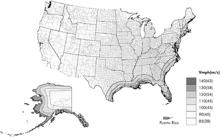
7 Lateral Forces 2003 Missouri Tornado Lateral Forces 2003 Missouri Tornado 2012 IRC Wall IRC Wall 26 Introduction: Lateral Forces Wind Speed Introduction: Lateral Forces Wind Speed USA 2012 IRC Wall IRC Wall 28 Copyright 2013 International Code Council 7


8 Introduction: Lateral Forces Earthquake Introduction: Lateral Forces SDC United States 2012 IRC Wall IRC Wall 30 Topics Stiffened Walls Forces and History Limits Examples Wall Framing Hinge Load Path Lateral Forces Stiffened Walls History Hinge 2012 IRC Wall IRC Wall 32 Copyright 2013 International Code Council 8
 Shear Walls (Engineered) Prescribed material and nailing Calculated load, material and nailing Limitations 3-Stories Maximum")
 VS. Shear Wall (1) Areas requiring wind design in Table R301.")
9 Stiffened Walls Stiffened Walls Wall Framing Wall Framing Interior Finish Hinge Panel resistance imparted to wall framing (Prevents hinging) Braced Wall Panel (Prevents hinging) Hinge 2012 IRC Wall IRC Wall 34 Stiffened Walls Stiffened Walls BWP (Prescriptive) Shear Walls (Engineered) Prescribed material and nailing Calculated load, material and nailing Limitations 3-Stories Maximum Wind < 110 mph (1) SDC A-D 2 Others (see IRC Chap. 3) Typically without hold-downs VS. Applications Any building size/shape Wind no limit SDC no limit Calculations required Typically with hold-downs Braced Wall Panel (BWP) VS. Shear Wall (1) Areas requiring wind design in Table R301.2(4)B may not use the IRC for lateral provisions IRC Wall 35 Hold-down capacity calculated 2012 IRC Wall 36 Copyright 2013 International Code Council 9


10 Wall Topics R Wall "Where a building, or portion thereof, does not comply with one or more of the bracing requirements in this section, those portions shall be designed and constructed in accordance with Section R301.1.ʺ Forces and History Load Path Lateral Forces Stiffened Walls History Limits Examples 2012 IRC Wall IRC Wall 38 History of History of Wall Uniform Building Code 1927 All exterior walls and partitions shall be thoroughly and effectively angle braced. History of Southern Building Code 1946 Sheathing shall be applied on the exterior walls of buildings more than one story in height, corners shall be braced by a let-in 1 x 4 or 1 x 6 continuous diagonal brace. Uniform Building Code 1952 All exterior walls and partitions shall be thoroughly and effectively angle braced or sheathed with approved panels adequately nailed along all edges IRC Wall IRC Wall 40 Copyright 2013 International Code Council 10


11 History of History of Uniform Building Code 1970 All exterior walls and main cross stud partitions shall be effectively and thoroughly braced at each end, or as near thereto as possible, and at least every 25 feet of length by on of the following methods: A. Nominal 1-inch by 4-inch B. Wood boards of 5/8-inch C. Plywood sheathing D. Fiberboard sheathing E. Gypsum sheathing F. Particleboard sheathing The Southern Building Code of 1970 had similar requirements as did the National Building Code by IRC Wall IRC Wall 42 History of History of Uniform Building Code inch alternate braced wall panel added International Residential Code 2000 percentage requirement added wood structural panel bracing method added International Residential Code 2006 Alternate braced wall panel adjacent to door or window opening added sheathing 4:1 and 6:1 aspect ratio panels at garage door added 2012 IRC Wall IRC Wall 44 Copyright 2013 International Code Council 11
12 History of International Residential Code 2009 Methods renamed from number designation to abbreviation Wall bracing length determined by the greater length requirement from separate wind and seismic bracing length tables Intermittent portal frame at garage added sheathing with structural fiberboard added Table of effective braced length for braced panels less than 48 in. long added Braced panel end distance limit of 12.5 ft. cumulative for SDC A-C with intermittent bracing Additional bracing requirements for structures with masonry veneer moved to wall bracing section Anchorage for masonry foundations with short wall lengths added Angled wall lines added Imaginary braced wall lines added History of International Residential Code 2012 Reorganization of wall bracing section Simplification of end distance and distance between braced wall panels Simplification of braced wall line length New method Simplified Wall 2012 IRC Wall IRC Wall 46 Topics Topics Forces & History Limits Examples Forces & History Limits Examples Load Path Lateral Forces Limits Irregular Buildings Stiffened Walls History? Wind Exposure Questions 2012 IRC Wall IRC Wall 48 Copyright 2013 International Code Council 12
 16\" = Max.")
13 Limits Story Height Limits Story Height In-plane lateral forces Requirements for story height exist to limit the wind and seismic provisions In-plane forces (lateral forces along a wall line): Story height limit 11 ft. 7 in Stud height 10 ft. Except: Stud height may be increased to 12 ft., therefore maximum story height may be 13 ft. 7 in 10' = Max. Stud Height (1) 16" = Max. Floor Framing Height (2) 16" Max Floor Framing (Joist Depth) (1)R301.3 Item 1, Exception permits the stud height to be 12' provided bracing length is increased by a factor of 1.2. (2)R301.3 Permits floor framing depths greater than 16ʺ when maximum story height is 11'-7ʺ or less. Stud Height Story Height Story Height 2012 IRC Wall R IRC Wall R Limits Stud Height Size, Height and Spacing of Wood Studs - Table R602.3(5) BEARING WALLS NONBEARING WALLS Limits Story vs Stud Height Stud Extends Two Stories Stud Size (Inches) Laterally unsupported stud height (feet) Maximum spacing when supporting roof-ceiling assembly or habitable attic, only (inches) Maximum spacing when supporting one floor, plus a roof-ceiling assembly or habitable attic (inches) Maximum spacing when supporting two floors, a roof-ceiling assembly or habitable attic (inches) Maximum spacing when supporting one floor height (inches) Laterally unsupported stud height (feet) Maximum spacing (inches) 2 x x x Lateral Support Stud Height Stud Height Story Height Story Height 2 x x IRC Wall 51 Balloon Framing Platform Framing R IRC Wall 52 Copyright 2013 International Code Council 13


14 Limits - Seismic R Seismic provisions. Limits - Seismic Seismic Design Category C The seismic provisions of this code shall apply to Townhouses in SDC C, D0, D1 and D2 Detached one and two family dwellings in SDC D0, D1 and D2 One- & two-family Seismic requirements don't apply Townhouse Seismic requirements apply R IRC Wall IRC Wall 54 Limits - Seismic Limits - Townhouse Seismic Design Category Wind Requirements Only One- and twofamily Townhouses A & B N/A N/A C N/A Seismic Req. Apply D 0 Seismic Req. Apply Seismic Req. Apply D 1 Seismic Req. Apply Seismic Req. Apply R202 TOWNHOUSE Three or more attached units Units extend from foundation to roof Open space on at least two sides Open two sides D 2 Seismic Req. Apply Seismic Req. Apply Wind and Seismic Requirements R IRC Wall 55 R IRC Wall 56 Copyright 2013 International Code Council 14


15 Limits - Townhouse R202 TOWNHOUSE Three or more attached units Units extend from foundation to roof Open space on at least two sides Not open two sides (therefore, not a townhouse) R IRC Wall 57 Limits - Weight R Weight of Materials Average dead loads shall not exceed: 15 or 25 psf for roofs/ceiling assemblies 10 psf for floor assemblies 15 psf for exterior wall assemblies Wind Requirements Weight of materials provisions do not apply Seismic Requirements Weight of materials provisions apply 2012 IRC Wall 58 Limits - Weight Snow Load, R Load Design Method < 70 psf Prescriptive > 70 psf Engineered Limits Irregular Buildings Irregular building definitions R Irregular buildings Wind Requirements Irregular building provisions do not apply Seismic Requirements Irregular building provisions apply 2012 IRC Wall R IRC Wall 60 Copyright 2013 International Code Council 15
 Forces & History Limits Limits Examples Ground Wind Seismic Snow Speed Design Subject to Damage From Load (mph) Category Frost Line Weathering Termite Depth 70 <110 A-D 2 Winter Design Temp Ice")
16 Limits Topics CLIMATIC AND GEOGRAPIC DESIGN CRITERIA - TABLE R301.2(1) Forces & History Limits Limits Examples Ground Wind Seismic Snow Speed Design Subject to Damage From Load (mph) Category Frost Line Weathering Termite Depth 70 <110 A-D 2 Winter Design Temp Ice Barrier Underlayment Required Flood Hazards Air Freezing Index Mean Annual Temp Irregular Buildings Wind Exposure 2012 IRC Wall IRC Wall 62 Limits: Wind Exposure Limits: Wind Exposure R Wind Limitations and Wind Design Required When wind speeds are 110 mph or greater OR When IRC Figure R301.2(4)B requires wind design The following references may be used to design the walls to resist lateral forces: WFCM ICC 600 ASCE-7 AISI S230 (steel) IBC R Figure R301.2(4)B shows where the IRC wall bracing requirements do not apply. Another code or standard must be used to brace the walls against lateral loads. Figure R301.2(4)B 2012 IRC Wall IRC Wall 64 Copyright 2013 International Code Council 16
 and adjusted per Table R301.2(3) shall be used Limits: Wind Exposure R301.2.1 Wind limitations Figure R301.")


17 Limits: Wind Exposure R Wind Design Criteria Component and cladding loads for wall coverings, windows, etc. per Table R301.2(2) and adjusted per Table R301.2(3) shall be used Limits: Wind Exposure R Wind limitations Figure R301.2(7) 2012 IRC Wall 65 Cladding Failure 2012 IRC Wall 66 Limits: Wind Exposure Limits: Wind Exposure Exposure A: Large city centers with at least 50 percent of the buildings having a height in excess of 70 feet for a distance of 0.5 mile upwind from the structure being designed. Exposure B: Urban and suburban areas, wooded areas or other terrain with many closely spaced obstructions having the size of single family dwellings or larger. 70' Average 1/2 Mile R IRC Wall 67 R IRC Wall 68 Copyright 2013 International Code Council 17


18 Limits: Wind Exposure Limits: Wind Exposure Exposure C (1 of 2): Open with scattered obstructions or undulations generally less that 30 feet in height extending for 1,500 feet in any direction. Exposure C (2 of 2): Within Exposure B terrain, but located directly adjacent to open areas of Exposure C for a distance of more than 600 ft.. >30' More than 600' Exposure C terrain Exposure B terrain R IRC Wall 69 R IRC Wall 70 Limits: Wind Exposure Topics Exposure D: Flat, unobstructed areas exposed to wind flowing over open water for at least 1 mile. Extends inland 1,500 feet. Forces & History Limits Limits Examples 1 Mile 1,500' R Irregular Buildings Wind Exposure? Questions 2012 IRC Wall IRC Wall 72 Copyright 2013 International Code Council 18


19 Topics : BWL Spacing Forces & History Limits Examples Locate BWL Required Length BWP Location How many BWL's? Panel Material & Ends Sufficient Length Connections Start A B C End Foundation Simplified Wall 2012 IRC Wall IRC Wall 74 : BWL Spacing : BWL Spacing Loaded wall versus resisting walls A Length B 1 Width RESISTANCE RESISTANCE R202, R , R IRC Wall 75 R LOAD 2012 IRC Wall 76 Copyright 2013 International Code Council 19
 townhouses) BWL Spacing = 25' max. Permitted BWL Spacing to be = = 35' 35' max. 1. Permitted To accommodate to be = 50' one max.")
20 : BWL Spacing : BWL Spacing Loaded wall versus resisting walls A Length RESISTANCE 1 B Table R Wind Seismic BWL Spacing = 60' max. 1 A BWL Spacing B Width LOAD SDC DC 0,(only D 1,& applies D 2 (all to dwellings) townhouses) BWL Spacing = 25' max. Permitted BWL Spacing to be = = 35' 35' max. 1. Permitted To accommodate to be = 50' one max. when room bracing not exceeding length 900 increased. ft 2 2. For all BWLs when bracing length is increased and L/W < 3:1 2 BWL Spacing 2 RESISTANCE 2012 IRC Wall 77 Table R IRC Wall 78 : BWL Spacing : BWL Spacing 1 BWL 2 2 BWL 3 Spacing Spacing Locating BWL 2 here makes distance between BWL's less. R IRC Wall IRC Wall 80 Copyright 2013 International Code Council 20
21 : BWL Spacing : BWL Spacing Wall Lines with BWP Offset Limitations Wall lines with BWP that are counted as part of a BWL must be parallel to the BWL Offsets out-of-plane up to 4' are permitted for any wall line There is an angle wall exception which will be discussed later 1 20' A 25' B R ' R IRC Wall IRC Wall 82 : BWL Spacing : BWL Spacing 4' BWL 4' 4' 8' BWL R R IRC Wall IRC Wall 84 Copyright 2013 International Code Council 21
22 : BWL Spacing : BWL Spacing A B 4' A B 10' Max. 6' C 4' 16' Wind 20' Edge to Edge "X" End BWP Width C 4' 16' 24' 24' R IRC Wall 85 R IRC Wall 86 : BWL Spacing : BWL Spacing 6' Max.? 6' Max. 24' 18' 3' BWP BWP 25' R R IRC Wall IRC Wall 88 Copyright 2013 International Code Council 22

23 : BWL Spacing How many BWL's? : BWL Spacing R Angled Corners 24' 4' 2012 IRC Wall 89 Wall sheathing in a diagonal wall section may be counted for a wall line s bracing length if the diagonal wall line is 8 or less in length. R IRC Wall 90 : BWL Spacing Topics Angled Walls R Projected BWL Length from Angled Wall Line Angle (ft.) from BWL Angled Wall Line (degrees) Length 4 ft. 6 ft. 8 ft R Forces & History Limits Examples Locate BWL Required Length BWP Location Panel Material & Ends Sufficient Length Connections Foundation Simplified Wall 2012 IRC Wall IRC Wall 92 Copyright 2013 International Code Council 23


24 : Required Length : Required Length Wind Speed Seismic Risk When considering whether wind or seismic requirements control, a number of factors must be considered. Wall bracing length - either wind or seismic requirements may control. Use the longest required length. Hold-downs, Roof Ties, Limits if wind or seismic requirements require additional connections or limits, they must be applied regardless of which requirement set controls. Both wind speed and seismic risk must be considered when defining required wall bracing. The required bracing length is the greater of the two bracing lengths. Wind Requirements Braced wall line spacing Wall height Eave to ridge height Roof ties Seismic Requirements Wall length Braced wall line spacing Hold-downs Material weight limits 2012 IRC Wall IRC Wall 94 : Required Length Length Tables 2012 Two bracing length tables Wind Seismic Table R (1) Table R (3) Required bracing length is the maximum of the two tables bracing length x all adjustment factors R , Tables R (1), R (2), R (3) & R (4) 2012 IRC Wall 95 : Required Length Decision Tree for Determining Required Length Wind Table R (1) Required? All detached dwellings and townhouses Seismic Table R (3) Detached dwellings in SDC D 0 -D 2 Townhouses in SDC C-D 2 R , R , R IRC Wall 96 Copyright 2013 International Code Council 24
25 : Required Length Requirements Based on Wind Speed Wind Table based on: Wind Exposure Category B Mean roof height of 30 ft. Eave to ridge height of 10 ft. Wall height of 10 ft. Two braced wall lines Required bracing length is determined by: Wind speed Story location Wall line spacing method : Required Length Adjustments to the required bracing length for wind forces: Adjust required bracing length using Table R (2) Wind Exposure Category Adjustment Roof Eave to Ridge Height Adjustment Hold-down, Interior finish, GB fastener Adjustments # of BWLs Adjustment Wall Height Adjustment Table R (1) Only required when adjustment is greater than 1.0 Table R (2) 2012 IRC Wall IRC Wall 98 : Required Length : Required Length Requirements Based on Wind Speed Adjustment Factors Adjustment Factor Wind Exposure Category, Mean Roof Height Wind bracing adjustment factors are in Table R (2) 1. Wind exposure category 2. Eave-to-ridge height 3. Wall height 4. Number of braced wall lines lb hold-down on top story 6. Application of interior gypsum board finish 7. Gypsum board fastening Number of Exposure/Height Factor Stories Exposure B Exposure C Exposure D Table R (2) Table R (2) 2012 IRC Wall IRC Wall 100 Copyright 2013 International Code Council 25
26 : Required Length Adjustment Factor Roof Eave-to-Ridge Height Support Roof Eave-to-Ridge Height Condition <5' 10' 15' 20' Roof only Roof + floor Roof + 2 floors NP NP Not Permitted Eave-to-ridge height : Required Length Adjustment Factor Wall Height Wall Height (ft.) Adjustment Factor 8' ' ' ' ' 1.1 Roof sail area that contributes to total structure sail area Table R (2) 2012 IRC Wall 101 Table R (2) 2012 IRC Wall 102 : Required Length Adjustment Factor Number of Braced Wall Lines Number of Braced Wall Lines Table R (2) Adjustment Factor > Braced wall line x Braced wall line spacing 2012 IRC Wall 103 x x x x x x : Required Length Adjustment Factor Number of Braced Wall Lines Footnote c Number of Braced Wall Lines Adjustment Factor > Table R (2) Footnote c allows the adjustment factor to be 1.0 when the braced wall line spacing on exterior lines neglects the interior lines. For example when interior BWLs are only need for seismic bracing or when they are only needed to Table R (2) support 2012 BWLs IRC Wall in the story above. 104 x x x Braced wall line x Braced wall line spacing x x Copyright 2013 International Code Council 26

27 : Required Length Topics Adjustment Factors wind cont. Forces & History Limits Examples Adjustment Factor Additional 800-lb hold-down at each BWP for top story only Interior finish Gypsum board fastening 4 o.c. at all panel edges, blocked horizontal joints Method DWB,,, PBS, PCP, and HPS DWB,,, PBS, PCP, HPS, CS-, CS-G, and CS- Adjustment Factor GB 0.7 Table R (2)? Questions Locate BWL Required Length BWP Location Panel Material & Ends Sufficient Length Support Connections Simplified Wall 2012 IRC Wall IRC Wall 106 Topics : BWP Location Forces & History Limits Examples Locate BWL Required Length BWP Location Panel Material & Ends Sufficient Length Connections Foundation BWP, BWL & Spacing Simplified Wall R202, R , R IRC Wall IRC Wall 108 Copyright 2013 International Code Council 27


28 : BWP Location : BWP Location BWP Spacing 2009 and earlier 6' 21' unbraced length 10' BWP Spacing 2012 Edition 6' 20' unbraced length 10' 4' BWP 4' BWP 2' 25' o.c. 2' R IRC Wall IRC Wall 110 : BWP Location R Location of Braced Wall Panels, R Minimum Number of BWPs Placement Requirements BWP to begin no more than 10' feet from the end of a BWL. BWP located not more than 20' o.c. from edge to edge Two BWPs per BWL when BWL > 16 ft. AND Minimum 1-48 BWP or 2- reduced length BWPs for BWL < 16 ft. : BWP Location Braced Panel Starting Location Distance from Corner Wind Panel begins up to 10 ft. from the corner 10 MAX BWL 1 R , R ' to 12' (end of wall line) R , R Wall 2012 IRC Wall IRC 112 Corner Copyright 2013 International Code Council 28
 12.5' 8' 12.5' Not required 24\" Min. (b) 32\" Min.")
29 : BWP Location Overview 2009 and earlier Wall Parameter Panel end distance Corner return length Intermittent CS- CS- Wind & SDC A-C 12.5' Combined SDC D 0 -D 2 Wind & SDC A-C SDC D 0 -D 2 Wind & SDC A-C 0' or 8' (a) 12.5' 8' 12.5' Not required 24" Min. (b) 32" Min. (b) SDC D 0 -D 2 Not Permitted (a) For, 8' with 24" panel at corner or 1,800 lb hold down per R , exception items 1 & 2. (b) In lieu of a corner return, an 800 lb hold-down may be fastened to the side of the BWP closest to the corner per R , exception item 2. : BWP Location Overview 2012 IRC Wall Parameter Panel end distance Corner return length Intermittent Wind & SDC A-C SDC D 0 -D 2 CS-, CS-G, CS-PF Wind & SDC SDC A-C D 0 -D 2 Wind & SDC A-C 10' 0' or 10' (a) 10' 10' 10' CS- Not required 24" Min. (b) 32" Min. (b) SDC D 0 -D 2 Not Permitted (a) For, 10' with 24" panel at corner or 1,800 lb hold down per R , exception items 1 & 2. (b) In lieu of a corner return, an 800 lb hold-down may be fastened to the side of the BWP closest to the corner per Figure R , End Condition 2. R , Figure R IRC Wall IRC Wall 114 : BWP Location : BWP Location Summary 2009 Provisions Wind 2009 IRC 25' Centers "X" End BWP length 12'-6" Max. 25' Max. 48" 48" 48" R IRC Wall 115 R , Figures R (1) and R (2) 2012 IRC Wall 116 Copyright 2013 International Code Council 29
30 : BWP Location : BWP Location Summary 2012 Provisions 10' max 20' max Wind 2012 IRC 20' Spacing 10' End BWP length Does this meet code? No, 20' maximum exceeded. Wind 2012 IRC 20' Spacing 10' End BWP Width 48" 48" 48" 48" 48" R IRC Wall ' R IRC Wall 118 : BWP Location Does this meet code? Yes, 20' maximum not exceeded. 16' Wind 2012 IRC 20' Spacing 10' End BWP Length : BWP Location Does this meet code? No, BWP required to begin no more than 10 feet from the end of the wall. 12' Wind 2012 IRC 20' Spacing 10' End BWP Width 48" 48" 48" 48" 48" 36' R IRC Wall ' R IRC Wall 120 Copyright 2013 International Code Council 30
31 : BWP Location : BWP Location Does this meet code? No, width requirement not met. Wind & Seismic ' Spacing 10' End BWP Width 2012 IRC Does this meet code? Yes, width requirements are met. ABW Wind 2012 IRC 20' Spacing 10' End BWP Width 48" 48" 18' R IRC Wall ' 28" ABW Note: If BWP is supporting a story above, nailing must be a maximum 4ʺ o.c. 18' 28" ABW 2012 IRC Wall R Equals 4' : BWP Location Does this meet code? Yes, width requirements are met. 16" PFH Extended Header PFH 8' Note: Increase BWP width to 24" if supporting a story above. 18' Extended Header Wind & Seismic ' Spacing 10' End BWP Width 2012 IRC Wall R " PFH 3.7 Equals 4' Topics Forces & History? Questions Limits Locate BWL Required Length BWP Location Panel Material & Ends Sufficient Length Support Connections Simplified Wall Examples 2012 IRC Wall 124 Copyright 2013 International Code Council 31

32 Topics Topics Forces & History Limits Locate BWL Required Length BWP Location Panel Material & Ends Sufficient Length Connections Foundation Simplified Wall Examples Locate BWL Required Length BWP Location Panel Material & Ends Sufficient Length Connections Foundation Simplified Wall Panel Material & Ends Intermittent Sheathing Narrow Mixed Methods Interior Finish Ends Conditions Sheathing Joints 2012 IRC Wall IRC Wall 126 : Panel Material - Intermittent Intermittent Methods: LIB - Let-in diagonal brace DWB - 3/4" Diagonal wood boards - 3/8" Wood structural panel BV- 7/16" Wood structural panel with stone or masonry veneer - 1/2" Structural fiberboard GB - 1/2" Interior gypsum wallboard or gypsum sheathing particleboard PBS - 3/8" Particleboard sheathing PCP - Portland cement plaster on studs HPS - 7/16" Hardboard panel siding ABW - Alternate braced wall PFH - Portal frame with hold-downs PFG - Portal frame at garage door openings in SDC A-C Table R : Panel Material - Intermittent Method LIB Let-in Brace Angled 45 to 60 degrees from horizontal Extends continuously from bottom plate to top plate 1x4 lumber or approved metal strap Application limited 8' to 10' wall height only 8' to 10' 55" to 120" Table R IRC Wall IRC Wall 128 Copyright 2013 International Code Council 32


33 : Panel Material - Intermittent Method LIB Let-in Brace : Panel Material - Intermittent Method LIB Let-in Brace Must extend continuously from bottom plate to top plate Table R IRC Wall IRC Wall 130 : Panel Material - Intermittent Method DWB Diagonal Wood Boards Wood boards 3/4" (1" nominal) thick applied diagonally Studs spaced 24" max. : Panel Material - Intermittent Method DWB Diagonal Wood Boards 8' to 12' 4' min. Table R IRC Wall IRC Wall 132 Copyright 2013 International Code Council 33
 2012 IRC Wall 133 2012 IRC Wall 134 : Panel Material - Intermittent Method Structural Fiberboard Sheathing 1/2\" or 25/32\" thick Studs spaced 16\" o.c. max.")
34 : Panel Material - Intermittent Method Wood Structural Panel 3/8" min. thickness Wood structural panel defined in R604 : Panel Material - Intermittent Method Wood Structural Panel 8' to 12' 4' min. 48" 48" 48" Table R602.3(3) 2012 IRC Wall IRC Wall 134 : Panel Material - Intermittent Method Structural Fiberboard Sheathing 1/2" or 25/32" thick Studs spaced 16" o.c. max. Must conform to ASTM C 208 Nailing 3" o.c. edge, 6" o.c. field : Panel Material - Intermittent Method Structural Fiberboard Sheathing 8' to 12' Table R ' min IRC Wall IRC Wall 136 Copyright 2013 International Code Council 34


35 : Panel Material - Intermittent Method GB Gypsum Board 1/2" min. thick for studs spaced 24" o.c. max. 4' minimum length Nailing at 7" o.c. length: 8' to 12' Single sided = 0.5 x actual length Double sided = 1x actual length : Panel Material - Intermittent Method GB Gypsum Board No floating corners! Table R ' min IRC Wall IRC Wall 138 : Panel Material - Intermittent Method PBS Particleboard Sheathing 3/8" or 1/2" min. thickness Studs 16" o.c. max. 4' minimum length Nailing at 3" edge, 6" field Minimum 8d nails for 1/2" 8' to 12' thick sheathing : Panel Material - Intermittent Method PCP Portland Cement Plaster Studs 16" o.c. max. Installed in accordance with R703.6 Nailing 6" o.c. 8' to 12' Table R ' min. Table R ' min IRC Wall IRC Wall 140 Copyright 2013 International Code Council 35

 Minimum Length a (inches) Wall Height 8 ft. 9 ft. 10 ft. 11 ft. 12 ft.")
36 : Panel Material - Intermittent Method PCP Portland Cement : Panel Material - Intermittent Method HPS Hardboard Panel Siding 7/16" minimum thickness Studs 16" on center Nailing 4" o.c. edge and 8" o.c. field 8' to 12' Table R ' min IRC Wall IRC Wall 142 : Panel Material - Intermittent Method HPS Hardboard Panel Siding : Panel Material - Intermittent Minimum Length of BWPs Table R Minimum length for braced wall panels BWP Length 2012 IRC Wall 143 Method (See Table R ) Minimum Length a (inches) Wall Height 8 ft. 9 ft. 10 ft. 11 ft. 12 ft. Contributing Length (inches) DWB,,, PBS, 48 PCP, HPS, BV Actual b GB Double sided = Actual Single sided = 0.5 Actual LIB NP NP Actual b BWP Height 48 to 58 BWP Table R IRC Wall 144 Copyright 2013 International Code Council 36


 8 9 10")

37 : Panel Material - Intermittent Partial Credit for Narrow BWPs Table R Effective length of braced panels less than 48" For Methods DWB,,, PBS, PCP, HPS Actual Effective Length of BWP Length 8' 9' 10' 48" 48" 48" 48" 42" 36" 36" N/A 36" 27" N/A N/A BWP Height BWP Length 27" to 48" : Panel Material - Intermittent Method ABW - Alternate Braced Wall Equivalent to 48" panel For use on bottom story only Minimum length varies with SDC and height Nailing: Single story 6" o.c. min Bottom of two story 4" o.c. min Minimum hold-down capacity changes with SDC and height BWP R IRC Wall 145 R , Table R IRC Wall 146 : Panel Material - Intermittent Method ABW - Alternate Braced Wall Table R Minimum length for braced wall panels (excerpt) Minimum ABW Length Wall Height (ft.) SDC A-C SDC D 0 - D NP NP Height Table R Length : Panel Material - Intermittent Method ABW - Alternate Braced Wall Hold-down: A prefabricated metal anchoring device that attaches the framing of a wall system to the structure below. The hold-down prevents uplift of the studs and, thus overturning of the wall segment. Hold-down Foundation reinforcement required (Caused by moment from hold-downs) 2012 IRC Wall IRC Wall 148 Copyright 2013 International Code Council 37
 Hold-down capacity per Table R602.10.6.1 #4 bars top and bottom for bracing 12\" x 12\" min.")

 3\" o.c. nailing Min.")

38 : Panel Material - Intermittent Method ABW - Alternate Braced Wall Wind 8' to 12' SDC C, D 0,D 1 and D 2 8' to 10' Min. 3/8" thick wood structural panel sheathing Anchor bolts 1/2" (2) Hold-down capacity per Table R #4 bars top and bottom for bracing 12" x 12" min. footing : Panel Material - Intermittent Method PFH Intermittent Portal Frame 16" min panel length for 1-story, 24" min for 2-story Header 6' min. to 18' max. Each vertical panel replaces a 48" braced wall panel 8' to 10' PFH Opening PFH Opening Extended header PFH Figure R " or 24" min. R , Table R IRC Wall IRC Wall 150 : Panel Material - Intermittent Method PFH Intermittent Portal Frame 10' Max. Extended header 1,000 lb strap capacity (opposite side from sheathing) 3" o.c. nailing Min. 3/8" thick wood structural panel 4,200 lb strap type hold-down (1) 5/8" anchor bolt Figure R IRC Wall 151 Method PFH with taller walls Wall height up to 12 ft. tall Portal height limited to 10 ft. (top of header) Pony wall built above portal header 4 ft. max pony wall height Pony walls require tension straps (Table R ) Number of jack studs required for single portal post in Table R502.5(1) 2012 IRC Wall 152 Copyright 2013 International Code Council 38
 Min.")


 3\" o.c. nailing Min.")
39 : Panel Material - Intermittent Method PFH Intermittent Portal Frame : Panel Material - Intermittent Method PFH Intermittent Portal Frame Min. 1,000 lb strap (opposite side) Min. 1,000 lb hold-down Min. #4,200 hold-down Figure R Figure R IRC Wall IRC Wall 154 : Panel Material - Intermittent Method PFG Intermittent Portal Frame at Garage For use in SDC A-C only length = 1.5 x length of panel Minimum 24" length Header 6' min. to 18' max. : Panel Material - Intermittent Method PFG Intermittent Portal Frame at Garage Extended header Min. 1,000 lb strap (opposite side from sheathing) 10' Max. Extended header 1,000 lb strap capacity (opposite side) 3" o.c. nailing Min. 7/16" thick wood structural panel No hold-downs required R , Table R No hold-downs required (2) 1/2" anchor bolts 2012 IRC Wall 155 Figure R IRC Wall 156 Copyright 2013 International Code Council 39
 Number of jack studs required for single portal post in Table R502.")

40 Method PFG with taller walls Wall height up to 12 ft. tall Portal height limited to 10 ft. (top of header) Pony wall built above portal header 4 ft. max pony wall height Pony walls require tension straps (Table R ) Number of jack studs required for single portal post in Table R502.5(1) 2012 IRC Wall IRC Wall 158 : Panel Material - Intermittent Minimum Length of Narrow BWPs Table R Minimum length for braced wall panels (excerpt) Method (See Table R ) Minimum Length a (inches) Contributing Wall Height Length 8 ft. 9 ft. 10 ft. 11 ft. 12 ft. (inches) DWB,,, PBS, PCP, HPS, Actual b BV- SDC A, B and C ABW 48 SDC Do, D1 and D NP NP Supporting roof only c 20 c 48 PFH Supporting one story and roof c 29 c 48 PFG SDC A, B and C d 36 d 1.5 Actual b : Panel Material - Proprietary Other bracing methods per code report Prefabricated units Laminated Kraft-paper board Fiberboard in various thicknesses 2012 IRC Wall 159 R IRC Wall 160 Copyright 2013 International Code Council 40

41 : Panel Material - Proprietary Per Code Report : Panel Material - Proprietary Per Code Report 2012 IRC Wall IRC Wall 162 Topics Locate BWL Required Length BWP Location Panel Material & Ends Sufficient Length Connections Foundation Simplified Wall Panel Material & Ends Intermittent Sheathing Mixed Methods Interior Finish Ends Conditions Sheathing Joints : Panel Material - Sheathing Methods: CS- CS-G CS-PF CS- ly sheathed wood structural panel ly sheathed wood structural panel adjacent to garage openings ly sheathed portal frame ly sheathed structural fiberboard Table R IRC Wall IRC Wall 164 Copyright 2013 International Code Council 41
 R602.10.4.2, Table R602.10.5 2012 IRC Wall 165 : Panel Material - Sheathing Requirements: 1.")


42 : Panel Material - Main Concepts Allows for narrow BWP's without holddowns BWL's must be fully sheathed with wood structural panel or structural fiberboard sheathing (continuously sheathed) R , Table R IRC Wall 165 : Panel Material - Sheathing Requirements: 1. Sheath full height areas including gable ends 2. Sheath above and below openings 3. Adjacent openings determine minimum BWP length Too Narrow R & R IRC Wall 166 : Panel Material - : Panel Material - Aspect Ratio: The ratio of the height of a bracing unit to its length. Opening Height Opening Height Aspect Ratio = Height Length Aspect Ratio = 8' 4' = 2 Height Length Figure R IRC Wall 167 Table R IRC Wall 168 Copyright 2013 International Code Council 42

43 : Panel Material - 20' Max. 20' Max. : Panel Material - Method CS- Sheathing with Wood Structural Panel Area above and below openings fully sheathed including gable ends Min 3/8" wood structural panel sheathing BWP Infill Sheathing R & Figure R IRC Wall 169 Method CS- Sheathing with Structural Fiberboard Area above and below openings fully sheathed including gable ends Min 1/2" structural fiberboard sheathing R , Table R IRC Wall 170 : Panel Material - Wall Parameter ly Sheathed Wood Structural Panel CS-, CS-G, CS-PF ly Sheathed Structural Fiberboard CS- Wind applicability < 110 mph 100 mph : Panel Material - Method CS- Full-height sheathed wall segments having a length equal or greater than Table R are counted toward the total bracing length. Wall minimum length is based on wall height and height of the adjacent clear opening. Seismic applicability A - D 2 A - C Permitted wall heights 8' to 12' 8' to 12' Corner return length (both sides of corner) 24" Min. (or hold downs at first BWP) 32" Min. (or hold downs at first BWP) Panel end distance 10' 10' Table R , Figure R IRC Wall 171 Too Narrow Table R IRC Wall 172 Copyright 2013 International Code Council 43
 8 9 10 11 12 64 24 27 30 33 36 68 26 27 30 33 36 72 27 27 30 33 36 76 30 29 30 33 36 80 32 30 30 33 36 84 35 32 32 33 36 88 38 35 33 33 36 92 43 37 35 35 36 96 48 41 38 36 36 100 44 40 38 38 104 49")
 8 9 10 11 12 124 56 51 128 61 54 CS- 132 66 58 136 62 140 66 144 72 CS-G a 24 27 30 33 36 CS-PF <120 16 18 20 22 b 24 b a. Garage opening adjacent to method CS-G panel shall have header.")

44 : Panel Material - Method CS- Table R Minimum Length of Braced Wall Panels (in) Method CS- Adjacent Wall Height (ft.) Clear Opening Height (ft.) Adjacent Wall Height (ft.) Clear Method Opening Height (ft.) CS CS-G a CS-PF < b 24 b a. Garage opening adjacent to method CS-G panel shall have header. Max opening height includes header height. b. Max header height 10 feet, pony wall may be used above header. Table R IRC Wall : Panel Material - 8' Method CS- Too narrow to be counted 36' All panels less than 20 apart edge to edge 24" 108" 32" 24" 24" 24" < 20' < 20' < 20' R & Table R IRC Wall 174 : Panel Material - Method CS-G Wood structural panel adjacent to garage opening Full-height sheathed wall segments to either side of garage openings Roof covering dead loads of 3 psf or less (seismic requirement only) Applied to one wall line of garage only Panel length = bracing length 4:1 aspect ratio : Panel Material - Method CS-G Garage only, supporting roof with 3 psf covering. 12' Max Garage Opening Standard Header H/4 R , Table R IRC Wall 175 4:1 Aspect Ratio (24" min.) 2012 IRC Wall 176 Copyright 2013 International Code Council 44


45 : Panel Material - Method CS-PF portal frame Walls on either or both sides of openings in garage may have wall segment with a maximum 6:1 height-to-length ratio. No hold-downs required OK on raised floor Top of header at 10' max Top of wall at 12' max Panel length = bracing length : Panel Material - Method CS-PF Garage only, story above permitted. 10' max (12' max with pony wall) Garag Garage Opening e Openi ng H/6 Fully sheathed dwelling R IRC Wall 177 Extended Header 6:1 Aspect Ratio (16" min.) R , Table R IRC Wall 178 : Panel Material - Method CS-PF Figure R IRC Wall 179 : Panel Material - Methods PFH, PFG and CS-PF Table R : Tension Strap Capacity Required for Resisting Wind Pressures Perpendicular to 6:1 Aspect Ratio Walls MINIMUM WALL STUD FRAMING NOMINAL SIZE AND GRADE 2 4 No. 2 Grade MAXIMUM PONY WALL HEIGHT (feet) MAXIMUM TOTAL WALL HEIGHT (feet) MAXIMUM OPENING WIDTH (feet) BASIC WIND SPEED (mph) Exposure B Exposure C Tension strap capacity required (lbf) DR DR DR DR DR DR DR DR DR DR DR DR 2012 IRC Wall 180 Copyright 2013 International Code Council 45

 9 1775 2350 3500 3550 DR DR 16 4175 DR DR DR DR DR 9 1000 1000 1325 1375 1750 2550 16 1650 2050 2925 3000 3550 DR 18 2025 2450 3425 3500 4100 DR 9 1125 1500 2225 2275")

46 : Panel Material - Methods PFH, PFG and CS-PF cont. Table R cont.: Tension Strap Capacity Required for Resisting Wind Pressures Perpendicular to 6:1 Aspect Ratio Walls MINIMUM WALL STUD FRAMING NOMINAL SIZE AND GRADE 2 4 No. 2 Grade 2 6 Stud Grade MAXIMUM PONY WALL HEIGHT (feet) MAXIMUM TOTAL WALL HEIGHT (feet) MAXIMUM OPENING WIDTH (feet) BASIC WIND SPEED (mph) Exposure B Exposure C Tension strap capacity required (lbf) DR DR DR DR DR DR DR DR DR DR DR DR DR DR DR DR DR 2012 IRC Wall 181 : Panel Material - Method CS-PF Garage Door Garage Door Plan View R IRC Wall 182 : Panel Material - CS-G CS-PF 4 : Panel Material - Method CS- Sheathing with Structural Fiberboard Wall minimum length based on wall height and height of adjacent clear opening Maximum wall height = 12 Length requirements for braced wall panels in Table R Same minimum bracing length requirements as CS- Same aspect ratio (opening height limits) as CS IRC Wall 183 R IRC Wall 184 Copyright 2013 International Code Council 46


47 : Panel Material - Method CS- Too narrow to be counted 4:1 4:1 6:1 ~2:1 : Panel Material - Method CS- Too narrow to be counted 3:1 6:1 6:1 ~2.4:1 8' 24" BWP 0% to 65% H 24" BWP 0% to 65% H 0% to 65% H 40" BWP 8' 32" BWP 65% to 85% H 0% to 65%H 65% to 85% H 40" BWP 18' 18' R IRC Wall 185 R IRC Wall 186 Topics Basics: Mixing Methods Locate BWL Required Length BWP Location Panel Material & Ends Sufficient Length Connections Foundation Simplified Wall Panel Material & Ends Intermittent Sheathing Mixed Methods Interior Finish Ends Conditions Sheathing Joints R Item 1 BWP method variation permitted from story to story with any type of sheathing 2012 IRC Wall 187 R Item IRC Wall 188 Copyright 2013 International Code Council 47
48 Basics: Mixing Methods R Item 2 BWP method variation permitted from BWL to BWL within a story for intermittent sheathing Basics: Mixing Methods R Item 3 BWP method variation within a BWL permitted ONLY in SDC A-B and for detached houses in SDC C with intermittent bracing Greatest required bracing length for panel materials must be used. Not applicable for use with continuous sheathing OR dwellings in SDC D 0 -D 2 For continuous and intermittent sheathing, variation may only occur in SDC A-C with winds < 100 mph R Item IRC Wall 189 R Item IRC Wall 190 Basics: Mixing Methods R Item 4 Basics: Mixing Methods R Item 5 Mixing of CS-, CS-G and CS-FP along a BWL is permitted in any SDC R Item IRC Wall 191 BWP method variation in a BWL with continuous sheathing on exterior walls and intermittent on interior walls permitted ONLY in SDC A-B and for detached houses in SDC C Greatest required bracing length for all panel materials in BWL must be used Not applicable for dwellings in SDC D 0 -D 2 R Item IRC Wall 192 Copyright 2013 International Code Council 48
49 Topics Locate BWL Required Length BWP Location Panel Material & Ends Sufficient Length Connections Foundation Simplified Wall Panel Material & Ends Intermittent Sheathing Mixed Methods Interior Finish Ends Conditions Sheathing Joints Basics: Braced Panel Construction R Braced Wall Panel Interior Finish Material Interior Finish (Gypsum) Required ½" thickness min BWP Material Exceptions: 1. Wall panels braced with Methods GB, BV-, ABW, PFH, PFG and CS-PF. 2. When an approved interior finish material with an in-plane shear resistance equivalent to gypsum board is installed. 3. For all methods except LIB, omitting gypsum wall board is permitted when the length of bracing in Tables R (1) and R (3) is multiplied by the factors in Tables R (2) or R (4) IRC Wall 193 R IRC Wall 194 Basics: Braced Panel Construction Topics R Braced Wall Panel Interior Finish Material Interior Finish (Gypsum) Required ½" thickness min Method LIB Method LIB requires fasteners into interior finish at maximum 8" o.c. Locate BWL Required Length BWP Location Panel Material & Ends Sufficient Length Connections Foundation Simplified Wall Panel Material & Ends Intermittent Sheathing Mixed Methods Interior Finish Ends Conditions Sheathing Joints R IRC Wall IRC Wall 196 Copyright 2013 International Code Council 49
50 : End Conditions R End Conditions for Braced Wall Lines with Sheathing : End Conditions R End Conditions for Braced Wall Lines with Sheathing End Conditions BWP at Corner Condition 1 - Return panel on perpendicular wall Condition 2 - In lieu of a return panel, an 800 lb hold-down may be fastened to the corner stud. Condition 3 - Minimum 48 BWP, no return required return panel 24 minimum return panel 32 minimum R IRC Wall 197 End Conditions - BWP offset from corner Condition 4 - Corner panel and return panel on perpendicular wall Condition 5 - In lieu of a corner panel, an 800 lb hold-down may be fastened to end of the BWP. return panel and corner panel 24 minimum return panel and corner panel 32 minimum R IRC Wall 198 : Panel Material - Sheathing Corner Requirements Minimum required CS- = 24" corner detail CS- = 32" : End Conditions Table R602.3(1) Item 8 - Corner Stud Requirements Gypsum Gypsum Figure R ' 24" Corner 32" 36" 32" 36" 84" 84" BWP BWP 24" Corner BWP Material or Infill 16d nail at 12" o.c. 16d nail at 12" o.c. BWP Material or Infill 2012 IRC Wall ' Table R602.3(1) Item IRC Wall 200 Copyright 2013 International Code Council 50

51 Topics : Joints Locate BWL Required Length Panel Material & Ends Intermittent All vertical panel joints shall occur over studs BWP Location Panel Material & Ends Sufficient Length Sheathing Mixed Methods Interior Finish 48" 48" 48" Connections Foundation Ends Conditions Sheathing Simplified Wall Joints Gypsum Method GB Wood Structural Panel Method R IRC Wall IRC Wall 202 : Joints : Joints Horizontal Blocking R Exceptions Blocking is required at vertical edges of BWP's, except: 48" Exception 1 Vertical panel joints may occur over doubled studs when nailed at 10 o.c. with 10d box nails R Panel joints Blocking required at horizontal edges of BWP's. Braced Wall Panel Method R IRC Wall IRC Wall 204 Copyright 2013 International Code Council 51
52 : Joints Topics R Exceptions Horizontal Blocking Blocking is required at horizontal edges of BWP's Exceptions: 2. Blocking at horizontal joints is not required in infill areas. 3. Where the bracing length provided is 2x the minimum length required (Tables R (1) and R (3)) blocking at horizontal joints shall not be required in braced wall panels constructed using Methods,, GB, PBS or HPS. 4. When Method GB panels are installed horizontally, blocking of horizontal joints is not required. R IRC Wall 205 Forces & History? Questions Limits Locate BWL Required Length BWP Location Panel Material & Ends Sufficient Length Support Connections Simplified Wall Examples 2012 IRC Wall 206 Topics : Sufficient Length Forces & History Limits Locate BWL Examples What is the minimum length of bracing allowed in a braced wall line? Required Length (New) Section R BWP Location Panel Material & Ends Sufficient Length BWL < 16 ft.: Minimum 2 BWPs any length OR 1 BWP 48 long Connections BWL > 16 ft.: Minimum 2 BWPs Foundation Simplified Wall 2012 IRC Wall IRC Wall 208 Copyright 2013 International Code Council 52

53 : Sufficient Length : Sufficient Length Determine whether there is sufficient space to place all the required bracing in a BWL Add length of qualified braced wall panel lengths Check against required length Locate space to place narrow panels if needed Check end distances and spacing between panels Minimum panel width OK Distance between panels OK End distance OK First, we will review panel lengths 2012 IRC Wall IRC Wall 210 : Sufficient Length : Sufficient Length 48" + 48" Length = = 8 12" Minimum panel width OK Distance between panels OK End distance OK Length = 48" + 27" + 48" = " " min length requirement 2009/ " braced panel is allowed with a reduced effective length 48" 48" " 36" 48" Min panel width Distance between panels End distance ' Table R ' 2012 IRC Wall 211 Tables R , R IRC Wall 212 Copyright 2013 International Code Council 53

54 : Sufficient Length : Sufficient Length 48" + 48" Length = = 8 12" Minimum panel width OK Distance between panels OK End distance OK Method CS- 2' CS- 90 mph SDC A Bottom of Two Stories? NA 4' Complete analysis Wind Direction 37' 16" PFH 32" ABW 3.7 Tables R (1)&(2), R , R " 18" 40' 27" 27" 40' 9' 18' Table R IRC Wall IRC Wall 214 : Sufficient Length : Sufficient Length Basic Wind Speed (mph) < 90 (mph) Story Location Braced Wall Line Spacing (ft.) Minimum Total Length of Braced Wall Panels Required Along Each Braced Wall Line Method LIB Method GB (double sided) Methods DWB,,, PBS, PCP, HPS Sheathing Method CS- 2' CS- 90 mph SDC A Bottom of Two Stories 12' NA 4' Tables R (1)&(2), R , R IRC Wall Table R (1) IRC Wall 216 9' 21" Total Length = 11.5 vs. 12 Required is insufficient (From Table 40 BWL) 21" 40' 48" 48" Copyright 2013 International Code Council 54
55 : Sufficient Length : Sufficient Length Method CS- 2' CS- 90 mph SDC A Bottom of Two Stories 11.4' NA 4' Can interpolate for BWL spacing or for wall height x 12 = 11.4 Total Length = 11.5 vs Required Method CS- CS-G 90 mph SDC C One Story? NA Wind Direction 20' 22' is OK 40' 21" 21" 48" 48" Garage Opening 8' 9' 2' 16' 2' Tables R (1)&(2), R , R IRC Wall 217 Tables R (1)&(2), R , R IRC Wall 218 : Sufficient Length Basic Wind Speed (mph) < 90 (mph) Story Location Braced Wall Line Spacing (ft.) Minimum Total Length of Braced Wall Panels Required Along Each Braced Wall Line Method LIB Method GB (double sided) Methods DWB,,, PBS, PCP, HPS Sheathing IRC Wall Table R (1) 219 : Sufficient Length Method CS-G CS-G One Story 105 mph SDC C 5' NA Total Length = 4 vs. 5 Required Garage Opening is NG 2' 16' 2' Tables R (1)&(2), R , R IRC Wall 220 8' Copyright 2013 International Code Council 55
 Minimum Total Length of Braced Wall Panels Required Along Each Braced Wall Line Method LIB Method GB (double sided) Methods DWB,,, PBS, PCP, HPS Sheathing 10 3.5 3.5 2 2 20 7 7 4 3.5 30 9.5 9.5 5.")
56 : Sufficient Length Basic Wind Speed (mph) < 90 (mph) Story Location Braced Wall Line Spacing (ft.) Minimum Total Length of Braced Wall Panels Required Along Each Braced Wall Line Method LIB Method GB (double sided) Methods DWB,,, PBS, PCP, HPS Sheathing IRC Wall Table R (1) 221 : Sufficient Length Method CS-G CS-G One Story 105 mph SDC C 3.8' NA Interpolate bracing length: = /10 = x0.15 = 3.8 Total Length = 4 vs. 3.8 Required is OK Garage Opening 2' 16' 2' Tables R (1)&(2), R , R IRC Wall 222 8' : Sufficient Length : Sufficient Length PBS Bottom of Two Stories 10' 90 mph SDC A?? Wind Direction 4' 16' 4' 24' 2012 IRC Wall 223 Tables R (1)&(2), R , R ' 42' Basic Wind Speed (mph) < 90 (mph) Story Location Braced Wall Line Spacing (ft.) Minimum Total Length of Braced Wall Panels Required Along Each Braced Wall Line Method LIB Method GB (double sided) Methods DWB,,, PBS, PCP, HPS Sheathing IRC Wall Table R (1) 224 Copyright 2013 International Code Council 56
57 : Sufficient Length : Sufficient Length PBS Bottom of Two Stories 10' 90 mph SDC A 17 NA Total Length = 8 vs. 17 Required is insufficient 4' 16' 4' 24' Tables R (1)&(2), R , R IRC Wall 225 Basic Wind Speed (mph) < 90 (mph) Story Location Braced Wall Line Spacing (ft.) Minimum Total Length of Braced Wall Panels Required Along Each Braced Wall Line Method LIB Method GB (double sided) Methods DWB,,, PBS, PCP, HPS Sheathing IRC Wall Table R (1) 226 : Sufficient Length : Sufficient Length PBS Bottom of Two Stories 90 mph SDC A 14.6 NA Interpolated required bracing length: = 3 3 /10 = x0.3 = 14.6 Total Length = 8 vs Required is insufficient Method 90 mph SDC B Bottom of Two Stories? NA 10' Wind Direction 36' 20' 10' 48" 48" 4' 16' 4' 24' Tables R (1)&(2), R , R IRC Wall ' Tables R (1)&(2), R , R IRC Wall 228 Copyright 2013 International Code Council 57
 Minimum Total Length of Braced Wall Panels Required Along Each Braced Wall Line Method LIB Method GB (double sided) Methods DWB,,, PBS, PCP, HPS Sheathing 10 3.5 3.5 2 2 20 7 7 4 3.5 30 9.5 9.5 5.")
58 : Sufficient Length Basic Wind Speed (mph) < 90 (mph) Story Location Braced Wall Line Spacing (ft.) Minimum Total Length of Braced Wall Panels Required Along Each Braced Wall Line Method LIB Method GB (double sided) Methods DWB,,, PBS, PCP, HPS Sheathing IRC Wall Table R (1) 229 : Sufficient Length Method Bottom of Two Stories 7.5' < 8' 90 mph SDC B 7.5' NA 10' Placement Requirement 4' + 4' = 8' Wind Requirement 7.5' 8 ft. required, 8 ft. available 48" 48" 36' Wind Requirement 20' Centers 10' Ends BWP Width Length Tables R (1)&(2), R , R IRC Wall 230 : Sufficient Length : Sufficient Length PCP 105 mph SDC B Bottom of Two Stories? NA Wind Direction 36' 7' 8' 6' 8' 7' Tables R (1)&(2), R , R IRC Wall ' 8' 25' Basic Wind Speed (mph) < 110 (mph) Story Location Braced Wall Line Spacing (ft.) Minimum Total Length of Braced Wall Panels Required Along Each Braced Wall Line Method LIB Method GB (double sided) Methods DWB,,, PBS, PCP, HPS Sheathing IRC Wall Table R (1) 232 Copyright 2013 International Code Council 58
&(2), R602.10.4, R602.10.5 2012 IRC Wall 233 Tables R602.10.3(1)&(2), R602.10.4, R602.10.5 2012 IRC Wall 234 : Sufficient Length Basic Wind Speed (mph) < 90 (mph) Story Location Braced Wall Line Spacing (ft.")
59 : Sufficient Length Basics: Percentage PCP 105 mph SDC B Bottom of Two Stories 16' NA Total Length = 20 vs. 16 Required is OK Method Bottom of Two Story 90 mph SDC B? NA Wind Direction 28' 36' 7' 8' 6' 8' 7' 10' 36' 8' 48" 48" 36' Tables R (1)&(2), R , R IRC Wall 233 Tables R (1)&(2), R , R IRC Wall 234 : Sufficient Length Basic Wind Speed (mph) < 90 (mph) Story Location Braced Wall Line Spacing (ft.) Minimum Total Length of Braced Wall Panels Required Along Each Braced Wall Line Method LIB Method GB (double sided) Methods DWB,,, PBS, PCP, HPS Sheathing IRC Wall Table R (1) 235 Basics: Percentage Method Bottom of Two Story 90 mph SDC B 10.5' NA 10' Placement Requirement 4' + 4' = 8' Wind Requirement 10.5' 48" 36' Wind 20' Centers 10' Ends BWP Width Length Tables R (1)&(2), R , R IRC Wall " Copyright 2013 International Code Council 59
&(2), R602.10.4, R602.10.5 2012 IRC Wall 237 Topics Forces & History?")
60 Basics: Percentage Method Bottom of Two Story 90 mph SDC B 10.5' NA 10' Placement Requirement 4' + 4' = 8' Wind Requirement 10.5' 4' + 5' + 4' = 13' 48" 60" 36' Wind 20' Centers 10' Ends BWP Width Length 48" Tables R (1)&(2), R , R IRC Wall 237 Topics Forces & History? Questions Limits Locate BWL Required Length BWP Location Panel Material & Ends Sufficient Length Support Connections Simplified Wall Examples 2012 IRC Wall 238 Topics : Connections Forces & History Limits Examples BWP sole plates and top plates connections per Table R602.3(1) Items Locate BWL Required Length BWP Location Panel Material & Ends Sufficient Length Connections Foundation Simplified Wall 2012 IRC Wall 239 Excerpt from Table R602.3(1) Items Number, Type and Item Building Element Spacing of Fastener 13 Double top plates, face nail 10d ( oc Double top plates, minimum 24-inch offset of end joints, face nail in lapped area Sole plate to joist or blocking, face nail 8-16d (3 1 / ) 16d (3 1 / oc Sole plate to joist or blocking at 3-16d (3 1 / braced wall panels 16 oc 17 Stud to sole plate, toe nail 18 Top or sole plate to stud, end nail 3-8d (2 1 / ) or 2-16d (3 1 / ) 2-16d (3 1 / ) 19 Top plates, laps at corners and intersections, face nail 2-10d ( ) 2012 IRC Wall 240 Copyright 2013 International Code Council 60

 R602.10.8 Item 1, Figure R602.10.8(1) 2012 IRC Wall 241 Figure R602.10.8(1) & Table R602.")
 16d")
 16d nails at blocking @ 16\" o.c. R602.10.8 Item 2, Figure R602.10.8(2) 2012 IRC Wall 243 Figure R602.10.8(2) & Table R602.")
61 : Connections : Connections When braced wall panels are perpendicular to joists above or below, blocking shall be provided in line with the BWPs BWP BWP BWP 3.7 BWP Perpendicular to Framing 8d toenailed at 6" o.c. 8d (2-1/2" x 0.113") band or rim joist below BWP Full height blocking above and below BWP (3) 16d nails at 16" o.c. along BWP 16d (3-1/2" x 0.135") R Item 1, Figure R (1) 2012 IRC Wall 241 Figure R (1) & Table R602.3(1) 2012 IRC Wall 242 : Connections : Connections BWP Blocking (not parallel) Where joists are parallel to BWPs above or below where a parallel framing member cannot be located full-depth blocking at 16 inch spacing shall be provided BWP Parallel to Framing (3) 16d nails at 16" o.c. along BWP Full height 16" o.c. above and below BWP 8d nails toenailed at 6"o.c. 2-16d nails each side 3-8d nails toe-nailed at 16" o.c. (3) 16d nails at 16" o.c. R Item 2, Figure R (2) 2012 IRC Wall 243 Figure R (2) & Table R602.3(1) 2012 IRC Wall 244 Copyright 2013 International Code Council 61
 9.25\" or less 9.25\" to 15.25\" 15.25\" or less 15.25\" to 48\" (1) Rafter or truss plate connection per Table R602.3(1) Blocking 1 Not required, attach per R602.3(1) Per R602.10.8.2.2 Item 1 and Figure R602.")

62 : Connections BWP Connection Requirements to Roof Framing SDC Wind Speed SDC A, B, C Wind < 100 mph SDC D 0, D 1, D 2 Wind > 100 mph All SDCs Wind < 110 mph Distance (bottom of roof sheathing to top of plate) 9.25" or less 9.25" to 15.25" 15.25" or less 15.25" to 48" (1) Rafter or truss plate connection per Table R602.3(1) Blocking 1 Not required, attach per R602.3(1) Per R Item 1 and Figure R (1) Per R Item 2 and Figure R (1) Per R Item 3 and Figure R (2) or R (3) : Connections BWP Perpendicular to Rafters or Roof Trusses For SDC A, B and C and wind speeds less than 100 mph, where 9.25 < distance < to top of the rafters to perpendicular top plates The rafters connected to the top plates of braced wall panels with blocking In accordance with Figure R (1) and attached using Table R602.3(1). R IRC Wall IRC Wall Figure R (1) 246 : Connections BWP Perpendicular to Rafters or Roof Trusses For SDC D 0, D 1 and D 2 or wind speeds of 100 mph or greater, where distance < to top of rafters or roof trusses to perpendicular top plates rafters or roof trusses shall be connected to the top plates of braced wall panels with blocking in accordance with Figure R (1) and attached in accordance with Table R602.3(1) Figure R (1) 2012 IRC Wall 247 : Connections BWP Perpendicular to Rafters or Roof Trusses Roof Trusses per R For all Seismic Design Categories and wind speeds, where Distance > to top of rafters or roof trusses to perpendicular top plates Perpendicular rafters or roof trusses shall be connected to the top plates of braced wall panels in accordance with Figure R (2) or Figure R (3) Figure R (2) 2012 IRC Wall 248 Copyright 2013 International Code Council 62
 2012 IRC Wall 249?")


63 : Connections BWP Perpendicular to Rafters or Roof Trusses Topics Forces & History Limits Locate BWL Required Length Examples Roof Trusses per R Figure R (3) 2012 IRC Wall 249? Questions BWP Location Panel Material & Ends Sufficient Length Connections Foundation Simplified Wall 2012 IRC Wall 250 Topics : Foundation Forces & History Limits Examples Locate BWL Required Length BWP Location Panel Material & Ends Sufficient Length Connections Foundation Simplified Wall Soil friction Lateral bearing capacity Sliding Resisted by soil friction and lateral bearing capacity of soil. Weight of soil Weight of the structure and footing Bearing capacity of soil Overturning Resisted by weight of structure and footing, weight of soil on footing, and bearing capacity of soil IRC Wall IRC Wall 252 Copyright 2013 International Code Council 63

64 : Foundation Wall Foundation Requirements (R602.10) Code Section R , Figures R and R R , Figure R Provision Alternate wall bracing (ABW, PFH) Short concrete or masonry walls below BWPs SDC A-C Methods ABW and PFH required 1-#4 horizontal top and bottom of footing Rebar required complying with Figure R if wall length, height, and thickness are L 48" AND H > 12" AND T < 6" High Seismic Regions SDC D 0 -D 2 Methods ABW and PFH required 1-#4 horizontal at top and bottom of footing Rebar required complying with Figure R if wall length, height, and thickness are L 48" AND H > 12" AND T < 6 : Foundation Wall Section Requirements 3" For footings supporting an ABW or PFH panel #4 bars at top & bottom R IRC Wall IRC Wall 254 : Foundation Narrow Masonry Wall Requirements Only required for walls less than 48" long IRC Wall 255 Cripple Walls Main Concepts Code provisions defined in R Supported on continuous footings. There are two methods for determining the required braced panel length for cripple walls (R ). Cripple Wall A framed wall extending from the top of the foundation to the underside of the floor framing of the first story above grade plane IRC Wall 256 Copyright 2013 International Code Council 64
 or Redesignated as a Two-story Length from Tables R602.10.3(1) or (3) for Roof only Roof + Floor Length 14' BWP edge to edge 20' BWP edge to edge R602.10.11 2012 IRC Wall 257 Seismic Design Categories A-D 1 Cripple Wall Supporting Two Stories Length from Tables R602.")
 or (3) for Roof only Length from Tables R602.10.3(1) or (3) for Roof + 1 Floor BP length for Roof + 2 Floors 20' BWP edge to edge R602.10.11 2012 IRC Wall 258 Cripple Walls Cripple Walls Stacked framing not permitted Cripple Wall or Story Above Grade?")
65 Cripple Walls Cripple Walls Seismic Design Categories A-D 1 Cripple Wall Supporting One Story Length from Tables R (1) or (3) for Roof only 1.15 x (Roof only Length) or Redesignated as a Two-story Length from Tables R (1) or (3) for Roof only Roof + Floor Length 14' BWP edge to edge 20' BWP edge to edge R IRC Wall 257 Seismic Design Categories A-D 1 Cripple Wall Supporting Two Stories Length from Tables R (1) or (3) for Roof only Length from Tables R (1) or (3) for Roof + 1 Floor 1.15 x (Roof + 1 Floor BP Length) 14' BWP edge to edge or Redesignated as a Three Story Length from Tables R (1) or (3) for Roof only Length from Tables R (1) or (3) for Roof + 1 Floor BP length for Roof + 2 Floors 20' BWP edge to edge R IRC Wall 258 Cripple Walls Cripple Walls Stacked framing not permitted Cripple Wall or Story Above Grade? See Chapter 2 Definitions: Story Above Grade Grade Plane 2012 IRC Wall IRC Wall 260 Copyright 2013 International Code Council 65
 Frost depth controls in many areas 1/2\" bolt with 7\" min. embedment in concrete or masonry 7 bolt dia. min. to 12\" max. 6' Max. Footing width, W Table R403.")
66 : Foundation : Foundation Footings: Anchor bolt placement Bolts embedded 7 inches Total length = 7 + plate(s) depth + threaded end Footing depth Minimum 12 inches (R ) Frost depth controls in many areas 1/2" bolt with 7" min. embedment in concrete or masonry 7 bolt dia. min. to 12" max. 6' Max. Footing width, W Table R403.1 lists minimum footing widths End of Plate 2012 IRC Wall IRC Wall R : Foundation Topics Slab on Grade 7" 3-1/2" Raised Floor Forces & History Limits Locate BWL Examples 6" 6" 7" 1' 0" 1' 0" T P W W R IRC Wall 263? Questions Required Length BWP Location Panel Material & Ends Sufficient Length Connections Foundation Simplified Wall 2012 IRC Wall 264 Copyright 2013 International Code Council 66
67 Topics : Simplified Wall Forces & History Limits Locate BWL Required Length BWP Location Panel Material & Ends Sufficient Length Connections Foundation Examples Prescriptive Limits The structure must meet the following requirements: Seismic Design Category (SDC) A, B, or C (SDC A or B for townhouses) Basic Wind Speed of 90 mph or less with Wind Exposure Category A or B One or two story structure Wood structural panel () or structural fiberboard sheathing () is used to brace exterior walls with ½ in gypsum board fastened to the interior side of walls 60 ft. maximum length and width of the building Max eave-to-ridge height of 15 ft. Wall max height of 10 ft. Max ratio between long and short side of building: 3 to 1 Max cantilever of 24 inches beyond foundation No cripple walls in two story buildings Simplified Wall 2012 IRC Wall IRC Wall 266 : Simplified Wall : Simplified Wall Prescriptive Limits 1 or 2 story Building Length Advantages to the Simplified Method: No seismic requirements only occurs on the perimeter (exterior walls) (No braced wall line length or spacing) No additional adjustment factors to check No interpolation Braced Wall Panel Material 2012 IRC Wall IRC Wall 268 Copyright 2013 International Code Council 67
68 : Simplified Wall Procedure: : Simplified Wall Rectangle Circumscribing an Enclosed Building 1. Draw a rectangle around the perimeter of the building and stagger the required number of bracing units along the four wall lines IRC Wall 269 Figure R IRC Wall 270 : Simplified Wall Procedure cont.: 2. Identify the number of bracing units required on each side of the rectangle. : Simplified Wall Minimum Number of Units on Each Side of the Circumscribed Rectangle Story Level Eave-to Ridge Height (Feet) Minimum Number of Units on Each Long Side a,b Minimum Number of Units on Each Short Side a,b Length of short side (ft.) c Length of long side (ft.) c a. Interpolation shall not be permitted. b. Cripple walls or wood-framed basement walls in a walk-out condition of a one-story structure shall be designed as the first floor of a two-story house. c. Actual lengths of the sides of the circumscribed rectangle shall be rounded to the next highest unit of 10 when using this table. Table R IRC Wall IRC Wall 272 Copyright 2013 International Code Council 68
69 : Simplified Wall : Simplified Wall Methods for Simplified Wall Narrow Methods for Simplified Wall Material Wood Structural Panel Structural Fiberboard Sheathing Stud Spacing & Fastener Criteria Table R602.3(3) Max 16'' spacing Table R602.3(1) Fastener Spacing Criteria 6'' edge 12'' field 3'' edge 6'' field Unit Method Minimum Unit Length (feet) 3 Intermittent 4 3 Intermittent 4 Narrow Method Equivalent Units CS-G 0.5 CS-PF 0.5 PFH 1 PFG 0.75 Each narrow bracing method is worth one or less than one 3 ft. or 4 ft. bracing unit. a. Mixing of wood structural panel and structural fiberboard sheathing in one building is not permitted. b. and intermittent bracing units may be mixed from one story to another. c. and intermittent bracing unit methods may not be mixed within one story IRC Wall R , R R IRC Wall 274 : Simplified Wall Example SDC B Wind 90 mph, Wind Exposure B Method CS- 1 Story Walls - 9 ft. Eave to ridge height - 12 ft. Example Highlights: Strategic placement of bracing units One Story 90 mph SDC B NA 2012 IRC Wall '-4" A 59'-8" B 1. Draw rectangle around the entire building 2. Check the length of the N-S and E-W sides the of rectangle Less than 60 ft.? 2012 IRC Wall 276 OK Copyright 2013 International Code Council 69
70 : Simplified Wall Table R Minimum Number of Units 1 A 59'-8" CS- CS- CS- CS- B 1. 4 bracing units required along each wall line 2. With CS-, the minimum bracing unit length is 3 ft IRC Wall '-4" CS- 10'-2" CS- CS- PF CS- PF CS- PF CS- 18' 19'-6" 12' CS- 3. Panels must be within 12 ft. of the end of wall line and within 20 ft. of one another. Sufficient space? Yes, CS-PF units are only worth 0.5 units each so 5 B.U.s min will be needed on the south wall. Furthermore, 3 CS-PF are needed to space units less than 20 ft. apart IRC Wall A 59'-8" CS- B Topics CS- 25'-2" Forces & History Limits Examples 21'-8" CS- CS- Locate BWL Required Length 42 21'-2" Sufficient space? 22'-2" CS- CS- Yes, 4 CS- bracing units fit along the east and CSwest wall lines. CS IRC Wall 279? Questions BWP Location Panel Material & Ends Sufficient Length Connections Foundation Simplified Wall 2012 IRC Wall 280 Copyright 2013 International Code Council 70
71 Topics Examples Forces & History Limits Examples Wind 90 mph, Exp B, SDC A Symbol LIB Description Diagonal let-in Symbol Key Symbol ABW Description Alternate BWP Wind 90 mph, Exp B, SDC A Wind 85 mph, Exp B, SDC D 2 Wind 90 mph, Exp C, SDC B Wind 105 mph, Exp C, SDC B DWB GB PBS PCP Diagonal wood boards Wood structural panel Structural fiberboard Gypsum wallboard Particleboard Portland cement PFH CS- CS-G CS-PF CS- Alt. BWP adj. opening sheathing 4:1 6:1 sheathing HBS Hardboard 2012 IRC Wall IRC Wall 282 Topics Example: SDC A, Wind 90 mph, Exp B Forces & History Limits Examples Wind 90 mph, Exp B, SDC A Wind 90 mph, Exp B, SDC A Wind 85 mph, Exp B, SDC D 2 Wind 90 mph, Exp C, SDC B Wind 105 mph, Exp C, SDC B Example Attributes: SDC A, Single-family dwelling Wind 90 mph, Wind Exposure B Method Roof only (top of two stories) Wall height is 8 ft. Example Highlights: Top Story 90 mph SDC A percent based on wind. This structure is exempt from the seismic requirements. BWP's on the second floor can be placed over an opening on the first floor. BWP's are permitted to occur up to 10 feet away from the ends of BWL's IRC Wall IRC Wall 284 Copyright 2013 International Code Council 71
72 Top Story Wall Line mph 1, ft. A, B 7.5 ft. 24'-11" SDC A N/A A 36'-10" Upper Story 2012 IRC Wall 285 B Exposure Category B 30 ft. Mean Roof Ht. 10 ft. Eave to Ridge Ht. 10 ft. Wall Height 2 Braced Wall Lines Basic Wind Speed < 90 (mph) Story Location Minimum Required Length of Table R (1) Minimum Total Length (feet) of Braced Wall Panels Required Along Each Braced Wall Line Braced Wall Line Method Spacing LIB (feet) Method GB (double sided) Methods DWB,,, PCP, HPS CS, CS G, CS PF EXPOSURE CATEGORY B, 30 FT MEAN ROOF HEIGHT, 10 FT EAVE TO RIDGE HEIGHT, 10 FT WALL HEIGHT, 2 BRACED WALL LINES Basic Wind Speed (mph) MINIMUM TOTAL LENGTH (feet) OF BRACED WALL PANELS REQUIRED ALONG EACH BRACED WALL LINE 90 (mph) IRC Wall (mph) Story Location Braced Wall Line Spacing (feet) Methods DWB, Method GB Method LIB f, h,, PBS, (double sided) g PCP, HPS f,i Sheathing NP NP NP NP NP NP NP NP NP NP NP NP Exposure Category B 30 ft. Mean Roof Ht. 10 ft. Eave to Ridge Ht. 10 ft. Wall Height 2 Braced Wall Lines Basic Wind Speed < 90 (mph) Story Location Minimum Required Length of Table R (1) Minimum Total Length (feet) of Braced Wall Panels Required Along Each Braced Wall Line Braced Wall Line Method Spacing LIB (feet) Method GB (double sided) Methods DWB,,, PCP, HPS CS, CS G, CS PF EXPOSURE CATEGORY B, 30 FT MEAN ROOF HEIGHT, 10 FT EAVE TO RIDGE HEIGHT, 10 FT WALL HEIGHT, 2 BRACED WALL LINES Basic Wind Speed (mph) MINIMUM TOTAL LENGTH (feet) OF BRACED WALL PANELS REQUIRED ALONG EACH BRACED WALL LINE 90 (mph) IRC Wall (mph) Story Location Braced Wall Line Spacing (feet) Methods DWB, Method GB Method LIB f, h,, PBS, (double sided) g PCP, HPS f,i Sheathing NP NP NP NP NP NP NP NP NP NP NP NP Top Story Wall Line mph 1, ft. A, B 7.5 ft. 24'-11" SDC A N/A A BWP over opening below 36'-10" 9' 4' 4' 7' ' 4' 4' 10' Upper Story B 8 ft. OK 8 ft IRC Wall 288 OK Copyright 2013 International Code Council 72
73 Top Story Wall Line 90 mph 1, ft. A, B 7.5 ft. SDC A N/A A 36'-10" Upper Story B Top Story Wall Line 90 mph 1, ft. A, B 7.5 ft. SDC A N/A A 36'-10" Upper Story B 1 4' 4 4 4' 1 4' 4 9' 4' 4' 7' ' 24'-11" 4 4' 24'-11" 4 4' 10' 10' 2 4' 4 2 4' ' 4' 4' 10' 8 ft. OK 2012 IRC Wall ft. OK 2012 IRC Wall 290 Example cont.: SDC A, Wind 90 mph, Exp B Example Attributes: SDC A, Single-family dwelling Wind 90 mph, Wind Exposure B Method Roof plus 1 floor (bottom of two stories) Wall Height is 8 ft. 90 mph SDC A Bottom Story Bottom Story Wall Line 1 90 mph 1, ft. A, B 14 ft. 24'-11" SDC A N/A A 36'-10" Bottom Story B IRC Wall IRC Wall 292 Copyright 2013 International Code Council 73
74 2012 IRC Wall 12/11/2017 Bottom Story Wall Line 90 mph SDC A 1, ft. N/A A, B 14 ft. A 36'-10" 36'-10" Bottom Story B Bottom Story Wall Line 90 mph SDC A 1, 2 9 ft. N/A A, B 13 ft. A 36'-10" 36'-10" Bottom Story B 1 10' 6' 4' 10 ft. 1 10' 6' 4' 10 ft. NG OK 24'-11" 24'-11" 2 4' 4' 4' 8' 12 ft. OK ' x 0.9 = 9' 14' x 0.9 = 13' 4' 4' 4' 8' 12 ft. OK 2012 IRC Wall IRC Wall 294 Bottom Story Wall Line 90 mph SDC A 1, 2 9 ft. N/A A, B 13 ft. A 36'-10" Bottom Story B Bottom Story Wall Line 90 mph SDC A 1, 2 9 ft. N/A A, B 11.7 ft. A 36'-10" Bottom Story B 1 3' 3-6ʺ 1 3' 3-6ʺ 4-6ʺ 24'-11" 4-6ʺ 4-6ʺ 24'-11" 4-6ʺ 2 5-6ʺ 4-6ʺ 2 5-6ʺ 4-6ʺ The 3.5 ft. and 3 ft. segments qualify using Table R ft. NG 2012 IRC Wall ft. NG With the wall height adjustment, the required bracing length is 13 ft. x 0.9 = 11.7 ft ft. OK 2012 IRC Wall ft. OK Copyright 2013 International Code Council 74
75 2012 IRC Wall 12/11/2017 Bottom Story Wall Line 90 mph SDC A 1, 2 9 ft. N/A A, B 11.5 ft. A 36'-10" Bottom Story B Topics 1 3' 10' 6' 4' ʺ Forces & History Limits Examples Wind 90 mph, Exp B, SDC A 4-6ʺ 24'-11" 4-6ʺ Wind 90 mph, Exp B, SDC A Wind 85 mph, Exp B, SDC D ʺ 4 4 4' 4' 4 4' 8' 4-6ʺ Wind 90 mph, Exp C, SDC B Wind 105 mph, Exp C, SDC B 2012 IRC Wall IRC Wall 298 Example: SDC A, Wind 90 mph, Exp B Example 3 SDC A Wind 90 mph Method & GB 1 Story 8 ft. tall walls, 10 ft. eave to ridge height One Story GB One Story Example Highlights: Strategic placement of BWL's. Different bracing methods can be used together. Application of PFH 90 mph SDC A 90 mph SDC A 2012 IRC Wall '-10" '-8" A B C D 17'-2" 17' 27'-11" 15'-7" 4' 3'-8" 4' 8' 64'-6" 2012 IRC Wall 77'-8" 300 Copyright 2013 International Code Council 75
76 1 2 28'-10" '-8" A B C D 17'-2" 17' 27'-11" 15'-7" 4' 3'-8" 4' 8' 64'-6" 2012 IRC Wall 77'-8" 301 Exposure Category B 30 ft. Mean Roof Ht. 10 ft. Eave to Ridge Ht. 10 ft. Wall Height 2 Braced Wall Lines Basic Wind Speed < 90 (mph) Story Location Minimum Required Length of Table R (1) Minimum Total Length (feet) of Braced Wall Panels Required Along Each Braced Wall Line Braced Wall Line Method Spacing LIB (feet) Method GB (double sided) Methods DWB,,, PCP, HPS CS, CS G, CS PF EXPOSURE CATEGORY B, 30 FT MEAN ROOF HEIGHT, 10 FT EAVE TO RIDGE HEIGHT, 10 FT WALL HEIGHT, 2 BRACED WALL LINES Basic Wind Speed (mph) MINIMUM TOTAL LENGTH (feet) OF BRACED WALL PANELS REQUIRED ALONG EACH BRACED WALL LINE 90 (mph) IRC Wall (mph) Story Location Braced Wall Line Spacing (feet) Methods DWB, Method GB Method LIB f, h,, PBS, (double sided) g PCP, HPS f,i Sheathing NP NP NP NP NP NP NP NP NP NP NP NP One Story GB Wall Line A D 1, 3, 4 B C 2 90 mph?? SDC B NA Adjustment Factors: Wind Exposure B = BWLs = 1.45 Walls - 8 feet tall = 0.9 Eave to ridge height - 10 feet tall = 1.0 Total = 1.31 Use Table R (1) to determine required bracing length Exterior braced wall lines Add adjustment factor BWL A assume 20 ft. spacing Method = 4 ft. 4 x 1.45 x 0.9 = 5.2 ft. BWL D assume 50 ft. spacing Method = 9 ft. 9 x 1.45 x 0.9 = 11.7 ft. BWL 1, 3, 4 assume 30 ft. spacing Method = 5.5 ft. 5.5 x 1.45 x 0.9 = 7.2 ft. Interior braced wall lines BWL B assume 20 ft. spacing Method GB = 7 ft. 7 x 1.45 x 0.9 = 9.1 ft. BWL C assume 50 ft. spacing Method GB = 15.5 ft x 1.45 x 0.9 = 20.2 ft. BWL 2 assume 30 ft. spacing Method GB = 9.5 ft. 9.5 x 1.45 x 0.9 = 12.4 ft IRC Wall '-10" '-8" A 23.7 ft. OK B OK C OK D OK 16'-2" 16' 28'-5" 14'-7" 4' 14.8 ft. GB 3'-8" 2'-9" equivalent 23'-8" 14'-2" GB 18'-0" 41 ft. One Story GB 23'-0" 73'-8" Wall Line A D B C 4' 90 mph SDC B NA 25.2 ft. 8' 9'-8" 15'-6" 60'-6" 2012 IRC Wall 304 Copyright 2013 International Code Council 76

77 A B C D 17'-2" 17' 27'-11" 15'-7" Topics 1 28'-10" 4' 3 3 4' 4' One Story 4' Wall Line 90 mph SDC B 1, 3, ft. NA GB ft. 3 4' 8' 16 ft. OK Forces & History Limits Examples Wind 90 mph, Exp B, SDC A '-8" 3 4' PFH 3'-8" 20" typical PFH GB 5 4' PFH 77'-8" 4' 3 4' 3 GB 5 6' 4' 4' 3 64'-6" 2012 IRC Wall ft. OK 8 ft. OK 12 ft. OK? Questions Wind 90 mph, Exp B, SDC A Wind 85 mph, Exp B, SDC D 2 Wind 90 mph, Exp C, SDC B Wind 105 mph, Exp C, SDC B 2012 IRC Wall 306 Copyright Materials International Code Council is a Registered Provider with The American Institute of Architects Continuing Education Systems. Credit earned on completion of this program will be reported to CES Records for AIA members. Certificates of Completion for non-aia members are available on request. This program is registered with the AIA/CES for continuing professional education. As such, it does not include content that may be deemed or construed to be an approval or endorsement by the AIA of any material of construction or any method or manner of handling, using, distributing, or dealing in any material or product. Questions related to specific materials, methods, and services will be addressed at the conclusion of this presentation. This presentation is protected by US and International Copyright laws. Reproduction, distribution, display and use of the presentation without written permission of the speaker is prohibited. International Code Council IRC Wall IRC Wall 308 Copyright 2013 International Code Council 77
MBOIA IRC Wall Bracing. Mark Halverson. Maine Building Officials and Inspectors Association. First Last
 Wall Bracing This document was prepared for the MBOIA and based on the wind speeds and Seismic Design Categories for Maine and shall only be used as a reference since the Wind Speeds and the Seismic Design
2009 IRC Wall Bracing
 2009 IRC Wall Topics www.iccsafe.org Item no. 7102S09 Mark Halverson Manager Field Services Division P The Engineered Wood ssn. Topics Introduction: Lateral Forces Introduction Lateral Forces Getting Started
R Code and Commentary for 2012 NC Residential Code final 03/06/13
 R602.10 Code and Commentary for 2012 NC Residential Code final 03/06/13 Commentary italicized and printed in red 1. Section R602.10 -- provides charging language for two simplified bracing approaches (isolated
RB104-09/10 R602.7, R (New), Table R (New), Figures R (1)-(2) (New)
, Table R (New), Figures R (1)-(2) (New)") RB104-09/10 R602.7, R602.7.1 (New), Table R602.7.1 (New), Figures R602.7.1(1)-(2) (New) Proposed Change as Submitted Proponent: Joseph Lstiburek, Building Science Corporation 1. Revise as follows: R602.7
RB104-09/10 R602.7, R602.7.1 (New), Table R602.7.1 (New), Figures R602.7.1(1)-(2) (New) Proposed Change as Submitted Proponent: Joseph Lstiburek, Building Science Corporation 1. Revise as follows: R602.7
Wall bracing panel requirements
 Wall bracing panel requirements Building Inspections Exterior and interior walls must be braced in accordance with Minnesota State Building Code section R602 to resist wind loads and racking. Locations,
130 MPH EXPOSURE B WFCM GUIDE. Guide to Wood Frame Construction in High Wind Areas for One- and Two-Family Dwellings 2015 EDITION
 130 MPH EXPOSURE B WFCM GUIDE Guide to Wood Frame Construction in High Wind Areas for One- and Two-Family Dwellings 2015 EDITION Updates and Errata While every precaution has been taken to ensure the accuracy
ACCESSORY STRUCTURE Building permit information For 1 & 2-family dwellings
 ACCESSORY STRUCTURE Building permit information For 1 & 2-family dwellings Building Safety Department 400-2 nd Street South St. Cloud, MN 56301 (320) 255-7239 A building permit is required for any accessory
WFCM 130 MPH GUIDE EXPOSURE B WOOD FRAME CONSTRUCTION MANUAL GUIDE TO WOOD CONSTRUCTION IN HIGH WIND AREAS FOR ONE- AND TWO-FAMILY DWELLINGS
 130 MPH EXPOSURE B GUIDE WFCM WOOD FRAME CONSTRUCTION MANUAL GUIDE TO WOOD CONSTRUCTION IN HIGH WIND AREAS FOR ONE- AND TWO-FAMILY DWELLINGS A F & P A American Forest & Paper Association American Wood
RESIDENTIAL DETACHED STORAGE STRUCTURES (GARAGE)
") City Of Austin 500 Fourth Avenue N.E. Austin, Minnesota 55912-3773 Building Department 507-437-9950 Fax 507-437-7101 RESIDENTIAL DETACHED STORAGE STRUCTURES (GARAGE) *A Building permit is required for
City Of Austin 500 Fourth Avenue N.E. Austin, Minnesota 55912-3773 Building Department 507-437-9950 Fax 507-437-7101 RESIDENTIAL DETACHED STORAGE STRUCTURES (GARAGE) *A Building permit is required for
R CODE CHANGE PROPOSAL FORM (See instructions on page 2)
") CODE CHANGE PROPOSAL FORM (See instructions on page 2) Code: IRC 12/13 Sections 301.2.2.2.1 Proponent: Charles S. Bajnai, Chesterfield County, VA, ICC Building Code Action Committee 1. Delete as shown
CODE CHANGE PROPOSAL FORM (See instructions on page 2) Code: IRC 12/13 Sections 301.2.2.2.1 Proponent: Charles S. Bajnai, Chesterfield County, VA, ICC Building Code Action Committee 1. Delete as shown
GARAGES/ONE-STORY City of Grand Rapids Building Safety Division
 GARAGES/ONE-STORY City of Grand Rapids Building Safety Division 218-326-7601 www.cityofgrandrapidsmn.com This handout is intended only as a guide and is based in part on the 2015 Minnesota State Building
STRUCTURAL ISSUES IN RESIDENTIAL CONSTRUCTION. Presented by: Susan L. Lasecki P.E., S.E.
 STRUCTURAL ISSUES IN RESIDENTIAL CONSTRUCTION Presented by: Susan L. Lasecki P.E., S.E. Presentation Outline Gravity Design Load Paths from Roof to Foundation Roof Framing Floor Framing Wall Framing Lateral
Administrative Changes
 Revised 11/29/06 Knox County Residential Building Codes Significant Changes From The 1995 CABO One And Two Family Dwelling Code To The 2006 International Residential Code All one and two family dwellings
City of Bemidji Building Office City Hall 317 4th Street NW Bemidji, Minnesota Phone Fax emi mn s
 City of Bemidji Building Office City Hall 317 4th Street NW Bemidji, Minnesota 56601-3116 Phone 218-759-3573 Fax 218-759-3590 emi mn s Residential Header and Girder Spans Requirements 2015 MSBC Chapter
CHAPTER 3 BUILDINGS WITH WOOD FRAMED EXTERIOR WALLS 301 SCOPE
 CHAPTER 3 BUILDINGS WITH WOOD FRAMED EXTERIOR WALLS WOOD CHAPTER 3 301 SCOPE This chapter prescribes construction requirements for buildings where all exterior walls above the foundation are wood framed
Chapter 2 EARTHQUAKE-RESISTANCE REQUIREMENTS
 Chapter 2 EARTHQUAKE-RESISTANCE REQUIREMENTS This chapter explains the International Residential Code s (IRC s) general earthquake-resistance requirements as well as specific IRC requirements concerning
Wood Frame Construction Manual for One- and Two-Family Dwellings 2015 EDITION WORKBOOK
 WFCM Wood Frame Construction Manual for One- and Two-Family Dwellings 2015 EDITION WORKBOOK Design of Wood Frame Buildings for High Wind, Snow, and Seismic Loads 2015 Wood Frame Construction Manual Workbook
What is Conventional Construction?
 What is Conventional Construction? Copyright This presentation is protected by US and International Copyright laws. Reproduction, distribution, display and use of the presentation without written permission
PRESENTATION OUTLINE MUBEC & IRC APPLICABILITY & ADMIN. 6/17/2015 RESIDENTIAL STRUCTURAL SYSTEMS. Carmen B. Bombeke, P.E.
 MUBEC & IRC APPLICABILITY & ADMINISTRATION RESIDENTIAL STRUCTURAL SYSTEMS Carmen B. Bombeke, P.E. IRC FLOORS QUESTIONS & ANSWERS PRESENTATION OUTLINE Maine Uniform Building & Energy Code (MUBEC) IRC 2009
A Simple Solution for Meeting
 A Simple Solution for Meeting Narrow Wall Bracing Requirements AND BUILDING A STRONGER, SAFER HOME. APA s Narrow Wall Bracing Method, combined with walls that are fully sheathed with plywood or OSB, helps
Colorado Chapter of the International Conference of Building Officials. Building Guide. The Colorado Chapter of the International
 Building Guide Colorado Chapter of the International Conference of Building Officials Colorado Building Chapter of the International Guide Code Council Single Family Residential One Story Detached Garage
CITY OF CEDAR FALLS DEPARTMENT OF DEVELOPMENTAL SERVICES INSPECTION SERVICES DIVISION PHONE Residential Accessory Structures
 CITY OF CEDAR FALLS DEPARTMENT OF DEVELOPMENTAL SERVICES INSPECTION SERVICES DIVISION PHONE - 268-5161 Residential Accessory Structures This information has been compiled for the benefit of any person
POST FRAME BUILDING STANDARDS
 CASS COUNTY, MISSOURI BUILDING CODES, ENVIRONMENTAL HEALTH AND ZONING DEPARTMENT 30508 S. West Outer Road, Harrisonville, MO 64701 P- (816) 380-8134 F- (816) 380-8130 POST FRAME BUILDING STANDARDS 201.3
RB213-06/07 Table R
 RB213-06/07 Table R602.10.5 Proposed Change as Submitted: Proponent: Scott Beard, SE, City of Tacoma, WA Revise as follows: TABLE R602.10.5 a, b, c LENGTH REQUIREMENTS FOR BRACED WALL PANELS IN A CONTINUOUSLY
ORDINANCE. APPROVED EMERGENCY: (Yes) (No) VETOED: Date
 (No) VETOED: Date") ORDINANCE AN ORDINANCE OF THE COMMISSION OF KNOX COUNTY, TENNESSEE RESCINDING ARTICLE III. CABO ONE- AND TWO-FAMILY DWELLING CODE, SEC. 10-56, SEC. 10-57 AND SEC. 10-58 AND ADOPTING THE 2006 INTERNATIONAL
ORDINANCE AN ORDINANCE OF THE COMMISSION OF KNOX COUNTY, TENNESSEE RESCINDING ARTICLE III. CABO ONE- AND TWO-FAMILY DWELLING CODE, SEC. 10-56, SEC. 10-57 AND SEC. 10-58 AND ADOPTING THE 2006 INTERNATIONAL
Details for Exterior Brick Masonry Veneer Supported by Metal Plate Connected Wood Trusses
 Details for Exterior Brick Masonry Veneer Supported by Metal Plate Connected Wood Trusses Released May 20, 2009 Updated March 9, 2011 Introduction: Wood frame structures with attached brick masonry veneer
MAT109: Introduction to the Wood Frame Construction Manual
 MAT109: Introduction to the Wood Frame Construction Manual One of the documents published by AF&PA is the Wood Frame Construction Manual for One- & Two-Family Dwellings. The WFCM is referenced in the IRC
Anchor bolts ASTM F1554, Gr. 36 Wide flange beams ASTM A992, Fy = 50 ksi Misc. structural steel ASTM A36, Fy = 36 ksi
 STRUCTURAL NOTES MATERIAL STRENGTHS Structural Steel Reinforcing Steel Concrete Masonry Structural Lumber Anchor bolts ASTM F1554, Gr. 36 Wide flange beams ASTM A992, Fy = 50 ksi Misc. structural steel
2008 Special Design Provisions for Wind and Seismic
 2008 Special Design Provisions for Wind and Seismic Philip Line, P.E., Bradford K. Douglas, P.E., and Peter Mazikins, P.Eng. Introduction The 2008 edition of the Special Design Provisions for Wind and
CALCULATING WIND LOADS ON LOW-RISE STRUCTURES PER 2015 WFCM ENGINEERING PROVISIONS (STD342-1)
") CALCULATING WIND LOADS ON LOW-RISE STRUCTURES PER 015 WFCM ENGINEERING PROVISIONS (STD34-1) John Buddy Showalter, P.E. Vice President, Technology Transfer American Wood Council Description The Wood Frame
CALCULATING WIND LOADS ON LOW-RISE STRUCTURES PER 015 WFCM ENGINEERING PROVISIONS (STD34-1) John Buddy Showalter, P.E. Vice President, Technology Transfer American Wood Council Description The Wood Frame
Evaluation of Full-Scale House Testing Under Lateral Loading
 Evaluation of Full-Scale House Testing Under Lateral Loading Prepared for National Association of Home Builders Prepared by NAHB Research Center 400 Prince Georges Boulevard Upper Marlboro, MD 20774-8731
FIGURE R502.2 FLOOR CONSTRUCTION
 CHAPTER 5 FLOORS 11 I SECTION R501 GENERAL R501.1 Application. The provisions of this chapter shall control the design and construction of the floors for all buildings including the floors of attic spaces
ESR-2894 Reissued April 2014 This report is subject to renewal April 1, 2016.
 ICC-ES Evaluation Report ESR-894 Reissued April 04 This report is subject to renewal April, 0. www.icc-es.org (800) 4-87 () 99-04 A Subsidiary of the International Code Council DIVISION: 07 00 00 THERMAL
City of Republic Community Development Girder and Header Spans for Exterior Walls
 City of Republic Community Development Girder and Header Spans for Exterior Walls Revision Date: January 2017 2012 IRC Table R502.5(1) Girder Spans a and Header Spans a for Exterior Bearing Walls (Maximum
2012 Wood Frame Construction Manual: Wind Load Distribution on Buildings Load Paths
 2012 Wood Frame Construction Manual: Wind Load Distribution on Buildings Load Paths Presented by: William L. Coulbourne, PE Copyright Materials This presentation is protected by US and International Copyright
TOWN OF SOUTH KINGSTOWN REQUIREMENTS FOR BUILDING PERMITS RESIDENTIAL SINGLE FAMILY
 TOWN OF SOUTH KINGSTOWN REQUIREMENTS FOR BUILDING PERMITS RESIDENTIAL SINGLE FAMILY ACCESSORY STRUCTURES (Barn, Garage, Shed) ********************************* BUILDING PERMIT APPLICATIONS FOR ACCESSORY
On Cold-Formed Steel Construction. Light Gauge Steel Engineers Association Washington, D.C Toll Free (866)
") TECHNICAL NOTE On Cold-Formed Steel Construction $5.00 Light Gauge Steel Engineers Association Washington, D.C. 20005 Toll Free (866) 465-4732 www.lgsea.com DESIGN OF BY-PASS SLIP CONNECTORS IN COLD-FORMED
TECHNICAL NOTE On Cold-Formed Steel Construction $5.00 Light Gauge Steel Engineers Association Washington, D.C. 20005 Toll Free (866) 465-4732 www.lgsea.com DESIGN OF BY-PASS SLIP CONNECTORS IN COLD-FORMED
CHAPTER 5 FLOORS SECTION R501
 CHAPTER 5 FLOORS SECTION R501 GENERAL R501.1 Application. The provisions of this chapter shall control the design and construction of the floors for all buildings including the floors of attic spaces used
ADVANCED FRAMING LUMBER
 ADVANCED FRAMING LUMBER When it's built right, it's oncenter! QUALITY SERVICE VALUE Product Guide At A Glance Introduction 2 Design Properties 2 Wall Stud Design Example 3 Studs - Vertical Load 4 Wall
Lateral load basics Code acceptance of Standard. Standard Overview 2008 Wind & Seismic Standard. Wind. Wind Load Path. IBC Section 1604.
 Outline 2005/2008 Special Design Provisions for Wind & Seismic Standard Lateral load basics Code acceptance of Standard 2005/2008 Wind & Seismic Standard Overview 2008 Wind & Seismic Standard John Buddy
FEMA P-593 STEP-BY STEP PRESCRIPTIVE RETROFIT FOR CRIPPLE WALL BRACING & ANCHORAGE TO FOUNDATION
 INTRODUCTION Objective of provisions: The provisions of IEBC Appendix Chapter A3 are intended to reduce hazard of earthquake-induced damage (IEBC A301.1). These provisions are not intended to eliminate
ILLUSTRATED GUIDE. For Seismic Design of Houses. Lateral Bracing Requirements Part 9 BC Building Code 2012
 ILLUSTRATED GUIDE For Seismic Design of Houses Lateral Bracing Requirements Part 9 BC Building Code 2012 This guide has been developed to assist house designers and builders in understanding and complying
Special Inspections for Wood Construction BCD710 Michelle Kam-Biron, PE, SE, SECB Senior Director, Education American Wood Council
 Special Inspections for Wood Construction BCD710 Michelle Kam-Biron, PE, SE, SECB Senior Director, Education American Wood Council Copyright Materials This presentation is protected by US and International
LPI 56 Technical Guide
 LPI 56 Technical Guide Floor & Roof Applications Product Specifications & Design Values 2 Floor Tables 3 Uniform Floor Load (PLF) Tables: Simple s 4 Uniform Floor Load (PLF) Tables: Continuous s 5 Uniform
TYPICAL BEARING WALL FRAMING
 BASIC WOOD FRAMING City of Grand Rapids Building Safety Division 218-326-7601 www.grandrapidsmn.org This handout is intended only as a guide and is based in part on the 2007 Minnesota State Building Code,
Individual Truss Marking Is it a Building Code Requirement?
 Introduction: Individual Truss Marking Is it a Building Code Requirement? Released April 1, 2010 On January 1, 2008, the 2007 edition of the California Building Code (CBC) 1 was adopted for use and replaced
Gold Bond BRAND Gypsum Sheathing
 BRAND 09 06 29 16 00/NGC 43/NGC brand is a moisture-resistant sheathing installed on the outside of exterior framing as a substrate for exterior claddings. It is manufactured with a treated water-resistant
SECTION PLATE CONNECTED WOOD TRUSSES
 SECTION 06173 PLATE CONNECTED WOOD TRUSSES PART 1 GENERAL 1.01 SUMMARY A. Section Includes: 1. Shop fabricated wood trusses for roof and floor framing. 2. Bridging, bracing, and anchorage. B. Related Sections:
PHOTO 1: View from Inside the Structure. Note the Rotation of the WSP, Failure at the Lower Leading Edge and Deformation of the Top Plate
 2009 International Residential Code (IRC) Braced Wall Panel Design Value Comparative Equivalency Testing Braced Wall Panel Design Values July 15, 2010 Introduction: SBCRI undertook 39 tests resulting in
DIVISION: WOOD, PLASTICS AND COMPOSITES SECTION: STRUCTURAL PANELS REPORT HOLDER: ENERCEPT, INC.
 0 Most Widely Accepted and Trusted ICC ES Evaluation Report ICC ES 000 (800) 423 6587 (562) 699 0543 www.icc es.org ESR 1780 Reissued 11/2017 This report is subject to renewal 11/2019. DIVISION: 06 00
LATERAL LOADS ON BRICK VENEER RESIDENTIAL STRUCTURES
 LATERAL LOADS ON BRICK VENEER RESIDENTIAL STRUCTURES W. Mark McGinley 1, PhD, PE and Eric N. Johnson 2, PE ABSTRACT In North American residential construction, brick veneer is typically used as a cladding
2003 International Residential Building Code
 2003 International Residential Building Code Section R305 Ceiling Height Habitable rooms, hallways, corridors, bathrooms, toilet rooms, laundry rooms and basements shall have a ceiling height of not less
Heel Blocking Requirements and Capacity Analysis. Overview Revised 3/22/2017
 Heel Blocking Requirements and Capacity Analysis Overview Revised 3/22/2017 SBCA has been the voice of the structural building components industry since 1983, providing educational programs and technical
Guide to Attaching Exterior Wall Coverings through Foam Sheathing to Wood or Steel Wall Framing
 Guide to Attaching Exterior Wall Coverings through Foam Sheathing to Wood or Wall Framing Released September 20, 2010 Updated December 4, 2012 Note: Tables for cladding attachments to wood framing have
VERTICAL AND HORIZONTAL LATERAL LOAD SYSTEMS
 TECHNICAL NOTE On Cold-Formed Steel Construction $5.00 Light Gauge Steel Engineers Association Washington, D.C. Toll-Free: 1 (866) 465-4732 www.lgsea.com DESIGN VALUES FOR VERTICAL AND HORIZONTAL LATERAL
ACCEPTANCE CRITERIA FOR METAL PLASTER BASES (LATH) PREFACE
 PREFACE") ICC EVALUATION SERVICE, INC. Evaluate P Inform P Protect ACCEPTANCE CRITERIA FOR METAL PLASTER BASES (LATH) AC191 Approved May 2008 Effective June 1, 2008 Previously approved February 2008, October 2007,
ICC EVALUATION SERVICE, INC. Evaluate P Inform P Protect ACCEPTANCE CRITERIA FOR METAL PLASTER BASES (LATH) AC191 Approved May 2008 Effective June 1, 2008 Previously approved February 2008, October 2007,
The following are details of the code requirements of the 2015 International Residential Code for single-story decks.
 The following are details of the code requirements of the 2015 International Residential Code for single-story decks. The 2015 International Residential Code Section R507 contains additional information
Shear Wall Design Examples per 2015 WFCM and 2015 SDPWS
 Shear Wall Design Examples per 2015 WFCM and 2015 SDPWS Copyright Materials This presentation is protected by US and International Copyright laws. Reproduction, distribution, display and use of the presentation
SCREEN PORCHES 101 DEVELOPMENT RESOURCES, INC Permit Requirements
 SCREEN PORCHES 101 DEVELOPMENT RESOURCES, INC. 320-226.5189 www.101developmentresources.com While every attempt has been made to insure the correctness of this handout, no guarantees are made to its accuracy
LVL Product Guide 2.0E LVL 1.5E LVL
 LVL Product Guide 2.0E LVL 1.5E LVL Our Company Anthony Forest Products Company, a family-owned business founded in 1916, is headquartered in El Dorado, Arkansas. The company operates a southern pine lumber
SHEAR BRACE. Featuring ilevel Shear Braces for Engineered and Prescriptive Applications iLevel8 (
 WALL SOLUTIONS SHEAR BRACE 2006 IBC/IRC Code Accepted* *Achieved code evaluation report recognition (ICC ES ESR-2652) for compliance with the 2006 IBC/IRC Featuring ilevel Braces for Engineered and Prescriptive
WIND & SEISMIC 2008 EDITION ASD/LRFD WITH COMMENTARY. American Forest & Paper Association. American Wood Council ANSI/AF&PA SDPWS-2008
 2008 EDITION ANSI/AF&PA SDPWS-2008 Approval Date: August 4, 2008 ASD/LRFD WIND & SEISMIC Special Design Provisions for Wind and Seismic WITH COMMENTARY American Forest & Paper Association American Wood
2015 Special Design Provisions for Wind and Seismic Philip Line, P.E., John Buddy Showalter, P.E., Michelle Kam-Biron, P.E., S.E., Jason Smart, P.E.
 2015 Special Design Provisions for Wind and Seismic Philip Line, P.E., John Buddy Showalter, P.E., Michelle Kam-Biron, P.E., S.E., Jason Smart, P.E. The 2015 Edition of Special Design Provisions for Wind
Part III Building Planning and Construction
 Part III Building Planning and Construction CHAPTER 3 BUILDING PLANNING SECTION R301 DESIGN CRITERIA R301.1 Application. Buildings and structures, and all parts thereof, shall be constructed to safely
Part III Building Planning and Construction
 Part III Building Planning and Construction CHAPTER 3 BUILDING PLANNING SECTION R301 DESIGN CRITERIA R301.1 Application. Buildings and structures, and all parts thereof, shall be constructed to safely
Considerations for Outof-Plane. Design
 Considerations for Outof-Plane Wall and Uplift Design WoodWorks Texas Workshops December, 2016 Overview Uplift Wall Design Wind Loads Wind loads acting on buildings are modeled as uniform surface loads.
Minimum Requirements For One & Two Family Structures FBC 6 th Edition (2017)
") Pinellas County Building Department Reviewed : Date: Phone: Owner s Name: Permit Number: CB_ - Property Address: Contractor: Phone: Minimum Requirements For One & Two Family Structures FBC 6 th Edition
Pinellas County Building Department Reviewed : Date: Phone: Owner s Name: Permit Number: CB_ - Property Address: Contractor: Phone: Minimum Requirements For One & Two Family Structures FBC 6 th Edition
DIVISION: FINISHES SECTION: GYPSUM BOARD REPORT HOLDER: PANEL REY, S.A.
 0 Most Widely Accepted and Trusted ICC ES Evaluation Report ICC ES 000 (800) 423 6587 (562) 699 0543 www.icc es.org ESR 3831 Reissued 12/2017 This report is subject to renewal 12/2018. SECTION: 09 29 00
HILLSBOROUGH TOWNSHIP CODE ENFORCEMENT
 HILLSBOROUGH TOWNSHIP CODE ENFORCEMENT SAMPLE GUIDE FOR RESIDENTIAL DECKS revised 7 16 Call before you dig! 1 800 272 1000 New Jersey One Call. Utility Mark Out. THIS GENERIC GUIDE IS NOT ALL INCLUSIVE
DIVISION: WOOD, PLASTICS AND COMPOSITES SECTION: WOOD I JOISTS REPORT HOLDER: LOUISIANA PACIFIC CORPORATION
 0 Most Widely Accepted and Trusted ICC ES Report ICC ES 000 (800) 423 6587 (562) 699 0543 www.icc es.org ESR 1305 Reissued 08/2016 This report is subject to renewal 08/2018. DIVISION: 06 00 00 WOOD, PLASTICS
Part III Building Planning and Construction
 Part III Building Planning and Construction CHAPTER 3 BUILDING PLANNING SECTION R301 DESIGN CRITERIA R301.1 Application. Buildings and structures, and all parts thereof, shall be constructed to safely
The better way to build TM. Installation Manual FOUNDATION SIPs & FROST WALLS SIPs
 The better way to build TM Installation Manual FOUNDATION SIPs & FROST WALLS SIPs November 2016 PWF FOUNDATION & FROST WALL SIPs Installation Manual Table of Contents Topics General Requirements....................................
Plan Check No. Checked by: An Appointment Is Required for Verification
 SUPPLEMENTAL CORRECTION SHEET UNREINFORCED MASONRY (URM) RETROFIT ( 2002 LABC ) Plan Check No. Checked by: Permit Appl. # An Appointment Is Required for Verification Job Address: For appt. call: APPLICATION
Wall Bracing. Part 1: Basic Components for Code Compliant Bracing
 The Pennsylvania Housing Research/Resource Center Wall Bracing. Part 1: Basic Components for Code Compliant Bracing Builder Brief: BB0807 Bo Kasal, Hankin Chair, Director of Research PHRC, and Jay Crandell,
SDPWS. Special Design Provisions for Wind & Seismic 2015 EDITION
 SDPWS Special Design Provisions for Wind & Seismic 2015 EDITION ANSI/AWC SDPWS-2015 Approval date September 8, 2014 Updates and Errata While every precaution has been taken to ensure the accuracy of this
The administration part of the International
 PART 1 Administration Chapter 1 Chapter 1 Scope and Administration R105.2 Fences Exempt from Permit The administration part of the International Residential Code (IRC) covers the general scope, purpose,
REPORT HOLDER: MITEK USA, INC. (FORMERLY USP STRUCTURAL CONNECTORS) SOUTHCROSS DRIVE, SUITE 200 BURNSVILLE, MINNESOTA EVALUATION SUBJECT:
 SOUTHCROSS DRIVE, SUITE 200 BURNSVILLE, MINNESOTA EVALUATION SUBJECT:") 0 Most Widely Accepted and Trusted ICC-ES Evaluation Report ICC-ES 000 (800) 423-6587 (562) 699-0543 www.icc-es.org ESR-2787 Reissued 05/2017 This report is subject to renewal 05/2019. DIVISION: 03 00
0 Most Widely Accepted and Trusted ICC-ES Evaluation Report ICC-ES 000 (800) 423-6587 (562) 699-0543 www.icc-es.org ESR-2787 Reissued 05/2017 This report is subject to renewal 05/2019. DIVISION: 03 00
System Report. Design for Combined Shear and Uplift from Wind. and equipment, and Section Analysis
 ystem Report R-101B JANUARY 2010 Design for Combined hear and Uplift from Wind 1. BAI OF THE YTEM REPORT n 2009 and 2006 International Building Code: ections 104.11 Alternative materials, design and methods
DIVISION: THERMAL AND MOISTURE PROTECTION SECTION: METAL ROOF PANELS SECTION: METAL WALL PANELS REPORT HOLDER:
 0 Most Widely Accepted and Trusted ICC ES Evaluation Report ICC ES 000 (800) 4 6587 (562) 699 0543 www.icc es.org ESR 3152 Reissued 08/2017 This report is subject to renewal 08/2018. DIVISION: 07 00 00
Joint Evaluation Report
 0 Joint Evaluation Report ICC-ES (800) 423-6587 (562) 699-0543 www.icc-es.org 000 ESR-1040 Reissued 09/2016 This report is subject to renewal 09/2018. DIVISION: 06 00 00 WOOD, PLASTICS AND COMPOSITES SECTION:
BUILDING CODES Presented by CORUM ENGINEERING
 BUILDING CODES Presented by CORUM ENGINEERING AGENDA I. The Basics of Foundations A. Footer Designs B. Foundation Walls 1. Non-Backfilled Walls 2. Backfilled Walls (Retaining Walls) C. Slabs vs. Crawl
The following preliminary issues may need to be addressed prior to an application for a building permit.
 INTRODUCTION Several types of structures are commonly utilized for detached residential accessory and agricultural buildings. The three most common types of structures are conventional light wood framing,
See the IRC for additional information. See CPD-DS Information Bulletin 100 for Requirements for 1 & 2 Family Dwelling plan submittals.
 As a customer service initiative, the Kansas City, Missouri, City Planning and Development Department/Development Services, in cooperation with the Greater Kansas City Home Builders Association, has developed
PR-L274 Nordic Structures Revised April 16, 2017
 Nordic TM PR-L274 Nordic Structures Revised April 16, 2017 Products: NI-20, 40, 40x, 60, 70, 80, 80x, 90, and 90x Prefabricated Wood I-s Nordic Structures 1100 Avenue des Canadiens-de-Montréal, Suite 504
Georgia State Amendments to the International Residential Code for One- and Two- Family Dwellings
 Georgia State Amendments to the International Residential Code for One- and Two- Family Dwellings (2006 Edition) Georgia Department of Community Affairs Planning and Environmental Management Division 60
Supplemental Plan Check Corrections Sheet for Structural Design - General (2011 LABC)
") Supplemental Plan Check Corrections Sheet for Structural Design - General (2011 LABC) Plan Check / PCIS Application #: Job Address P.C. Engineer (E-mail: firstname.lastname@lacity.org ) Phone For instruction
Supplemental Plan Check Corrections Sheet for Structural Design - General (2011 LABC) Plan Check / PCIS Application #: Job Address P.C. Engineer (E-mail: firstname.lastname@lacity.org ) Phone For instruction
TECHNICAL NOTE On Cold-Formed Steel Construction
 TECHNICAL NOTE On Cold-Formed Steel Construction $5.00 6a 1996 Light Gauge Steel Engineers Association Washington, D.C. Toll-Free: 1 (866) 465-4732 www.lgsea.com DESIGN GUIDE FOR PERMANENT BRACING OF COLD-FORMED
City of Hughson Building Safety Division 7018 Pine Street Hughson, CA (209)
") City of Hughson Building Safety Division 7018 Pine Street Hughson, CA 95326 (209) 883-4054 RESIDENTIAL ATTACHED PATIO COVERS Patio covers are one story roofed structures not more than 12 feet above grade,
City of Hughson Building Safety Division 7018 Pine Street Hughson, CA 95326 (209) 883-4054 RESIDENTIAL ATTACHED PATIO COVERS Patio covers are one story roofed structures not more than 12 feet above grade,
LP OSB Sheathing & Structural 1 Sheathing
 Rated OSB Sheathing Roof Panels Span Ratings Max. Live Load Thickness Span Rating for Roofs (lbs)** 3/8" 24/0 30 7/16" 24/16 40 15/32" 32/16 70 1/2" 32/16 70 19/32" 40/20 130 23/32" 48/24 175 1-1/8" 48
ANALYSIS AND DESIGN OF MOMENT RESISTING MIDWALL BY THE STEEL NETWORK, INC.
 ANALYSIS AND DESIGN OF MOMENT RESISTING MIDWALL BY THE STEEL NETWORK, INC. Paul Lackey, P.E., Muhammad Ghoraba, Nabil A. Rahman, Ph.D., P.E. and Kurtis Kennedy MidWall is a hold-down product intended to
Specifications. Materials and Fabrication. Physical Properties. Environmental Impact. Sizes. Installation - General Requirements.
 Specifications Materials and Fabrication Physical Properties LP FlameBlock Fire-Rated OSB Sheathing panels are made of oriented strand board (OSB) with a fire-resistant, cementitious coating (Pyrotite
Building Guide. Colorado Chapter of the International Code Council
 12/29/16 Building uide Colorado Chapter of the International Code Council How to Use this uide Check with your jurisdiction regarding type of submittal (paper or electronic) and for additional requirements.draw
Floor Truss Ribbon Board Load Path
 Floor Truss Ribbon Board Load Path SRR No. 1506-16 Structural Building Components Association (SBCA) July 26, 2016 SBCA is an APPROVED SOURCE This research report is based on practical scientific research
DIVISION: FINISHES SECTION: GYPSUM BOARD ACCESSORIES REPORT HOLDER: CONLAB, INC. dba PREST ON CO.
 0 Most Widely Accepted and Trusted ICC ES Evaluation Report ICC ES 000 (800) 423 6587 (562) 699 0543 www.icc es.org ESR 1812 Reissued 11/2017 This report is subject to renewal 11/2018. DIVISION: 09 00
DIVISION: FINISHES SECTION: PORTLAND CEMENT PLASTERING REPORT HOLDER: SUPERWALL MANUFACTURING, INC.
 0 Most Widely Accepted and Trusted ICC ES Evaluation Report ICC ES 000 (800) 423 6587 (562) 699 0543 www.icc es.org ESR 2214 Reissued 08/2017 This report is subject to renewal 07/2019. DIVISION: 09 00
DIVISION: WOOD, PLASTICS AND COMPOSITES SECTION: SHEAR WALL PANELS REPORT HOLDER: SIMPSON STRONG TIE COMPANY INC.
 0 Most Widely Accepted and Trusted ICC ES Evaluation Report ICC ES 000 (800) 423 6587 (562) 699 0543 www.icc es.org ESR 1267 Reissued 10/2017 This report is subject to renewal 10/2018. DIVISION: 06 00
Residential Inspector s Guide: Building and Energy based on the 2009 International Residential Code Chapters 1-11
 Residential Inspector s Guide: Building and Energy based on the 2009 International Residential Code Chapters 1-11 Residential Inspector s Guide Building and Energy Based on the 2009 IRC, Chapters 1-11
FOUNDATIONS CHAPTER 4
 CHAPTER 4 FOUNDATIONS > > > SECTION R401 GENERAL R401.1 Application. The provisions of this chapter shall control the design and construction of the foundation and foundation spaces for all buildings.
Temporary Construction Loads Over I-Joist Roofs And Floors
 T E C H N I C A L N O T E Temporary Construction Loads Over I-Joist Roofs And Floors Number J735C July 2012 During construction of light-frame structures it is common to see relatively heavy loads placed