INS T A LLA T I O N G U I D E
|
|
|
- Ashley Rich
- 6 years ago
- Views:
Transcription


1 INS T A LLA T I O N G U I D E
2 TENSAR GEOGRIDS The System is a costeffective and easy-to-install alternative for projects with grade changes. The System owes its long-term performance and durability to high strength Tensar Uniaxial (UX) Geogrids. Due to their stiff interlocking capabilities, Tensar Geogrids stand the test of time, performing better than other commercially available geosynthetics. The System featuring Tensar Geogrids is one of the many patented soil reinforcement systems available for a variety of grade change applications. For more information, visit Introduction l Architects, Engineers, Contractors and owner/developers are under constant pressure to find economical alternatives for their grade separation projects. Typical solutions call for traditional wall systems but they often find these can be expensive to install and time consuming to construct. In a range of applications, they are finding a better solution is the Wire-Formed Retaining Wall System from Tensar International (TI). The System provides a dependable and cost-effective structural solution for the most challenging grade separation applications. It is a wire-formed, geogridreinforced retaining wall system featuring a positive mechanical connection for long-term structural stability. Beyond the performance capabilities, walls are easy to install and can be built to adapt to a wide variety of project conditions, design requirements and aesthetic options. Wall Facing Options Stone facing filled with native or imported stone that can be color, size and shape specified for a desired look and feel Vegetated facing with a natural appearance that can be designed by local landscape architects to blend with the natural surroundings Architectural finishes facing is veneer treated with a stacked stone or shotcrete sculpted finish providing a unique and traditional look This manual provides a guideline for construction and quality control of the installation for both stone- and vegetated-faced walls. It should be provided to the Engineer, the construction quality assurance inspector and the Contractor. For more specific instructions on installing special architectural finishes, please contact your local Tensar Representative. System s Components Component Tensar Geogrids Facing Units Locking Tail Struts Geotextiles Turf Reinforcement Mats Full Engineering and Construction Services Function High-density polyethylene (HDPE) structural geogrids internally reinforce the fill materials. Inert to chemical and biological degradation, they can be used with non-select fill or even recycled concrete. Galvanized welded wire baskets provide permanent facial stability during placement and compaction of fill material, and simplify facing alignment. Locking struts hold down the geogrid to the basket tail, and help stiffen the facing element to maintain alignment. Separation filter fabric provides a barrier between the reinforced backfill material and the stone fill at the face. Permanent, erosion-control blankets that aid in vegetation establishment and provide long-term turf reinforcement. Only used in vegetated-faced applications. Detailing, design, site assistance and stamped drawings for each project upon request.


 The Tensar technical advisor is not authorized to countermand any details or instructions in these guidelines, or on the approved construction")
3 1. Responsibilities for Construction Compliance l 2. Materials & Handling l The Contractor must construct the wall in accordance with the contract documents, plans and specifications. The Contractor is also responsible for the verification of line, grade and other physical features. The Tensar technical advisor may assist the Contractor and the inspection staff with the procedures within this manual and the contract plans, documents and specifications. The advisor may be onsite at the start of construction and thereafter only as requested or necessary. MATERIALS SUPPLIED Tensar Uniaxial (UX) and Biaxial (BX) Geogrids Facing Units Locking Tail Struts Non-woven needle punched geotextile, Erosion Control Blanket (ECB), or Turf Reinforcement Mat (TRM) from North American Green (depending on facing option) The Tensar technical advisor is not authorized to countermand any details or instructions in these guidelines, or on the approved construction drawings, without the express written agreement of the Engineer. Tensar Uniaxial Geogrid Tensar Biaxial Geogrid Tensar Uniaxial Geogrid Locking Tail Strut Erosion Control Blanket Locking Tail Strut Galvanized Facing Unit Connection Facing Unit Connection Stone-faced option Vegetated-faced option 2
4 HANDLING WALL MATERIALS Tensar Geogrids are shipped in roll form. The Contractor is responsible for off-loading the rolls. Prior to the removal of the labels, the Contractor should color-code each of the geogrid types using spray paint on the edges and ends of the rolls. For physical dimensions of wall materials, see chart below. Facing Units are delivered in bundles while the Locking Tail Struts come in clear bags. Geotextile, ECB and TRM products are shipped in roll form. All materials are to be off-loaded by the Contractor. It is the Contractor s responsibility to verify the quantities shipped and the condition of the materials. CONTRACTOR SUPPLIED MATERIALS Select or plantable fill Cable ties or tie wire Utility saw for field cutting of geogrid Alignment system materials (laser, stringline, etc.) Side cut shears for field cutting of Facing Units 4 ft level All labor, equipment and supervision necessary to perform the total wall construction If certifications are required by the contract documents, and if requested by the Contractor, they will be supplied along with the material that is shipped. It is the Contractor s responsibility to ensure that the Engineer is provided this information. Geosynthetic Wall Materials type size WEIGHT UX-MSE Geogrid 4.36 ft wide x 200 or 250 ft long lbs BX Geogrid 9.8 or 13 ft wide x 164 or 246 ft long lbs Geotextile (stone face) 3.75 ft wide x 360 ft long 37 lbs ECB/TRM (vegetated face) 6.5 ft x 55.5 ft/6.7 ft x 108 ft lbs


5 Prepare for wall construction by clearing the site and cutting and color-coding the Tensar Geogrid. 3. Wall Preparation l Verify the condition, approval and receipt of the System s Facing Units, Locking Tail Struts, Tensar Geogrid and fill materials. Materials should arrive in good condition. Tensar will not replace materials that have been accepted by the Contractor. The subgrade should be approved by the owner s Engineer before proceeding with the wall construction. Any soils found unsuitable by the Engineer should be treated in a manner approved by the Engineer. Color-code and pre-cut the geogrids and geotextiles to the lengths stated on the plans. An easy way to cut the geogrids is using a circular saw. Make the cut next to the heavy transverse bars that span the width of the rolls. As geogrids are cut, mark and tag them according to the length and type, and then stockpile them for later use. Grade and proof roll subgrade. Install offset stringline, story pole or other control to check and maintain wall alignment and grade. Locking Tail Strut Facing Unit (See Notes 1 and 2) 6 in. (typ.) Locking Tail Strut Geotextile Filter Fabric Tensar Uniaxial Geogrid in accordance with elevation view Erosion Control Blanket (ECB) Offset varies 6 in. (min.) Tensar BX1120 Geogrid 48 in. (min.) top and bottom Reinforced Fill 18 in. (min.) 2 in. (min.) 4 in. (max.) Face Stone Reinforced Fill 6 in. (min.) Facing Unit (See Notes 1 and 2) 6 in. (min.) Bottom Wrap of C350 TRM 3 in. (min.) Top Wrap of ECB extending beneath the Unit above Maximum Limit of Topsoil (see Note 3) shall not extend more than 3 in. under successive Facing Unit. Tensar Uniaxial or Biaxial Geogrid in accordance with elevation view Connection (Pull slack out of connection) Notes: 1. See Facing Unit detail for facing material and dimensions. 2. All Facing Units shall be galvanized per ASTM A123 after fabrication. 3. Optional A thin layer (2 in. min.) of finer stone (1/4 in. 1 in.) may be placed at the top of each unit to provide a level surface for the unit above. Connection (Connect Geogrid to Facing Unit and Notes: pull slack out of connection) 1. See Facing Unit detail for facing material and dimensions. 2. Facing Units shall be constructed from black steel. 3. Topsoil shall be loamy sand or finer gradation with 10% 15% organic content or material approved by a qualified landscape architect. Vegetation type shall be specified by a qualified landscape architect. Typical stone-faced wall detail Typical vegetated-faced wall detail 4


6 Insert the tail of the strut through the connection loops from the back and rotate upward to fasten to top of basket. 4. Wall Construction l Install the Facing Units on level grade. Butt the units end-to-end with the extended horizontal wires on one unit overlapping the adjacent unit. Note: The Facing Units may move forward during placement of the backfill and compaction. Set the first few courses 1 to 2 in. behind the face control line. Adjust setback of upper courses based on observed movements. Attach the end of the vertical wires of the adjacent units with cable ties, hog rings or wires to aid in maintaining alignment. Two full widths of UX Geogrids should be attached to each Facing Unit. The geogrid should not overlap adjacent units. The two outer ribs of the left geogrid should be placed between the outer two wires on the left side of the Facing Unit. The outer ribs of the other geogrid should be positioned between the outer wires on the right side of the Facing Unit. Two geogrid ribs should be positioned between each pair of wires. The transverse bar of the UX Geogrid will have to be cut in places to position pairs of ribs between pairs of wires. Cuts should be made only at apertures between wire pairs. Note: The transverse bar may need to be cut in a few more places to allow contact between the geogrid and the connection loops. A maximum of five cuts is allowed per geogrid roll width. Fasten geogrid to bottom wire with hog ring in areas where the geogrid is cut. Place face-backing as specified where face fill is finer than 2 in. Where 1 to 2 in. stone-face fill is specified, use BX1120 Geogrids to retain the stone. If a vegetated face is desired, use a permanent erosion control blanket from North American Green, such as C350 or SC150. The facebacking should be wide enough to cover the face and extend 6 in. under the fill. In instances where an erosion blanket is specified, the blanket should also extend 6 in. under the next installed Facing Unit. Insert the tail of the strut through the connection loops from the back and rotate upward to fasten to top of basket. Adjacent struts to be placed approximately 16 in. apart. One strut should be positioned between the two end wires to support the joint between Facing Units. When geogrid apertures do not perfectly align with the Basket s loops, cut the geogrid at the transverse bar that does not bear on a connection loop. Install Locking Tail Struts at both ends of the Facing Unit.

. A tab of at least 6 in. of geotextile is required to extend beyond the stone facing.")

7 In preparation for fill placement, pull the UX Geogrid toward the reinforced backfill zone so that it s tight against the connection. Maintain facing alignment. Place the first 9 in. backfill lift on top of the geogrid, while maintaining an open zone at the Facing Unit for the stone fill. The backfill should be placed near the wall face first and then proceed toward the geogrid tails. This will promote further geogrid tensioning. After the backfill is placed, position the pre-cut geotextile roll along the backfill s front edge (if required). A tab of at least 6 in. of geotextile is required to extend beyond the stone facing. Install facing fill materials in 9 in. loose lifts unless the plans require otherwise. To provide a level surface for the next Facing Unit, it is optional to use a thin layer of well-graded aggregate at the top of the basket. Note: Proper compaction at the wall face will minimize pillowing of the lower facing units as wall construction proceeds. Conventional wheeled compaction equipment may be used to compact reinforced fill beyond the 3 ft face zone to 95% of AASHTO-T99 maximum dry density or as otherwise specified. The compacted lift should be no more than 9 in. thick. Alignment adjustments will be required as the type of fill, moisture content, equipment and wall height will affect the amount of movement of an individual Facing Unit. Note: Facing Units may not move uniformly. Subsequent rows of units can be set with a relative setback based upon observed movements. The Contractor should check facing alignment as every course is placed. At the end of each day, the Contractor must ensure that the reinforced backfill is graded to drain away from the face of the wall. Berms and/or ditches must also be in place and functioning to prevent the entrance of runoff into the wall construction area. Compact facing and reinforced fill materials within 3 ft of the wall face or as the plans require. A vibratory plate tamper is recommended for compaction in this area. Install backfill over the geotextile separator fabric. Place stone fill within the Facing Units. 6 6

8 Tensar International Corporation 2500 Northwinds Parkway, Suite 500 Alpharetta, Georgia TENSAR-1 Distributed by: 2010, Tensar International Corporation. Certain products and/or applications described or illustrated herein are protected under one or more U.S. patents. Other U.S. patents are pending, and certain foreign patents and patent applications may also exist. Trademark rights also apply as indicated herein. Final determination of the suitability of any information or material for the use contemplated, and its manner of use, is the sole responsibility of the user. Printed in the U.S.A. SS_IG_10.10
TION GUIDE ALLA T INS
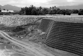
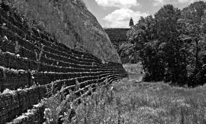
 INSTALLATION GUIDE TENSAR GEOGRIDS Easier installation makes the Sierra Slope Retention System a more affordable alternative to conventional retaining walls. The Sierra System owes its strength and durability
GEOSYTHETIC SLOPE SPEC-V0704rev.doc STANDARD SPECIAL PROVISION FOR GEOSYNTHETIC REINFORCED SLOPE CONSTRUCTION
 GEOSYTHETIC SLOPE SPEC-V0704rev.doc STANDARD SPECIAL PROVISION FOR GEOSYNTHETIC REINFORCED SLOPE CONSTRUCTION I. DESCRIPTION - This work consists of furnishing the required materials and construction of
SECTION SPECIFICATION FOR STONEBRIDGE RETAINING WALL SYSTEM
 SECTION 32 32 23 SPECIFICATION FOR STONEBRIDGE RETAINING WALL SYSTEM PART 1: GENERAL 1.01 Scope Work includes furnishing all materials, labor, equipment, and supervision to install a Stonebridge segmental
SECTION PERMEABLE INTERLOCKING CONCRETE UNIT PAVEMENT
 SECTION 32 14 13 19 PERMEABLE INTERLOCKING CONCRETE UNIT PAVEMENT SECTION 32 14 13 19 PERMEABLE INTERLOCKING CONCRETE UNIT PAVEMENT PART 1 - GENERAL 1.1 SUMMARY A. Section Includes: 1. Permeable Articulating
ARES RETAINING WALL SYSTEMS. installation guide and construction manual
 ARES RETAINING WALL SYSTEMS installation guide and construction manual When long-term performance and speed of construction are important, ARES Retaining Wall Systems offer unmatched advantages. Tensar
SPECIFICATIONS FOR PRECAST MODULAR BLOCK RETAINING WALL SYSTEM (revised 5/8/7)
") Page 1 of 7 STONE STRONG SYSTEMS SPECIFICATIONS FOR PRECAST MODULAR BLOCK RETAINING WALL SYSTEM (revised 5/8/7) PART 1: GENERAL 1.01 Description A. Work includes furnishing and installing precast modular
Page 1 of 7 STONE STRONG SYSTEMS SPECIFICATIONS FOR PRECAST MODULAR BLOCK RETAINING WALL SYSTEM (revised 5/8/7) PART 1: GENERAL 1.01 Description A. Work includes furnishing and installing precast modular
Description. This work shall consist of furnishing materials and placement of modular block wall constructed in accordance with
 MODULAR CONCRETE BLOCK RETAINING WALL WITH GROUND REINFORCING The Standard Specifications are revised as follows: 732-R-310r 1of 11 Rev. 12-03-03 SECTION 105, AFTER LINE 48, INSERT AS FOLLOWS: When constructing
MECHANICALLY STABILIZED EARTH (MSE) WALL SYSTEMS
 WALL SYSTEMS") DRAINAGE SOLUTIONS SINCE 1908 MECHANICALLY STABILIZED EARTH (MSE) WALL SYSTEMS PERMANENT AND TEMPORARY ENGINEERED WALL SOLUTIONS ECONOMICAL DURABLE VERSATILE ARMTEC.COM MSE RETAINING WALLS Armtec Mechanically
DRAINAGE SOLUTIONS SINCE 1908 MECHANICALLY STABILIZED EARTH (MSE) WALL SYSTEMS PERMANENT AND TEMPORARY ENGINEERED WALL SOLUTIONS ECONOMICAL DURABLE VERSATILE ARMTEC.COM MSE RETAINING WALLS Armtec Mechanically
Recyclex TRM TURF REINFORCEMENT MAT SPECIFICATION
 Recyclex TRM TURF REINFORCEMENT MAT SPECIFICATION PART I - GENERAL 1.01 Summary A. The Turf Reinforcement Mat (TRM) contains post-consumer recycled polyester fiber for the purpose of erosion control and
CONCRETE SEGMENTAL RETAINING WALL SYSTEM
 CONCRETE SEGMENTAL RETAINING WALL SYSTEM PART 1: GENERAL SPECIFICATIONS 1.01 Work Included A. Work shall consist of furnishing and constructing a Rockwood Classic 8, Classic 6 and Legend unit segmental
LANDSCAPE RETAINING WALLS
 SUDAS Standard Specifications Division 9 - Site Work and Landscaping Section 9070 - Landscape Retaining Walls LANDSCAPE RETAINING WALLS PART - GENERAL.0 SECTION INCLUDES A. Modular Block Retaining Walls
GABIONS AND REVET MATTRESSES
 GABIONS AND REVET MATTRESSES PART 1 - GENERAL 1.01 SECTION INCLUDES A. Gabions B. Revet Mattresses (Gabion Mattresses) 1.02 DESCRIPTION OF WORK A. Assembly and installation of gabions. B. Assembly and
Design Manual: Gravity Wall. Section 1
 Design Manual: Gravity Wall Section 1 A Design Manual: Gravity Wall General Information Company Information Verti-Block is the latest innovative forming system from Verti-Crete, LLC. Recognized worldwide
Section (02830) MODULAR CONCRETE RETAINING WALL
 MODULAR CONCRETE RETAINING WALL") Section 323223 (02830) MODULAR CONCRETE RETAINING WALL PART 1: GENERAL 1.01 Description A. Work shall consist of furnishing and constructing a VERDURA Retaining Wall System (or approved equal) in accordance
Section 323223 (02830) MODULAR CONCRETE RETAINING WALL PART 1: GENERAL 1.01 Description A. Work shall consist of furnishing and constructing a VERDURA Retaining Wall System (or approved equal) in accordance
VERTI-BLOCK - DESIGN MANUAL
 Company Information General Information Verti-Block is the latest innovative forming system from Verti-Crete, LLC. Recognized worldwide for outstanding aesthetics and performance, Verti-Crete s proprietary
Section ( ) SPECIFICATION FOR SEGMENTAL CONCRETE UNIT RETAINING WALL
 SPECIFICATION FOR SEGMENTAL CONCRETE UNIT RETAINING WALL") Section 02834 (32 32 23) SPECIFICATION FOR SEGMENTAL CONCRETE UNIT RETAINING WALL PART 1: GENERAL 1.01 Description A. Work shall consist of furnishing and construction of a County Materials Retaining Wall
Section 02834 (32 32 23) SPECIFICATION FOR SEGMENTAL CONCRETE UNIT RETAINING WALL PART 1: GENERAL 1.01 Description A. Work shall consist of furnishing and construction of a County Materials Retaining Wall
Uwall UNIVERSAL CONSTRUCTION MANUAL
 Uwall UNIVERSAL Retaining Wall System CONSTRUCTION MANUAL TM President s Letter CSI is a leader in its industry supplying precast infrastructure products throughout New England and beyond since 1972, developing
Redi Rock Specification and Installation Manual
 Redi Rock Specification and Installation Manual 1.0 General Scope This Specification covers the Design, Materials and Installation of Redi Rock modular block Retaining and Freestanding Wall systems as
MODULAR CONCRETE RETAINING WALL
 MODULAR CONCRETE RETAINING WALL PART 1: GENERAL 1.01 Description A. Work shall consist of furnishing and construction of a KEYSTONE Retaining Wall System or equal in accordance with these specifications
Design and Installation Guidelines for Retaining Walls. 1 P age. Geo Products, LLC 8615 Golden Spike Lane Houston, TX Phone:
 Design and Installation Guidelines for Retaining Walls 1 P age Geo Products, LLC 8615 Golden Spike Lane Houston, TX 77086 Phone: 281.820.5493 2011 Geo Products, Fax: 281.820.5499 LLC www.geoproducts.org
G R A V I T Y / G E O G R I D
 GRAVITY/GEOGRID MAGNUMSTONE Overview note: bolded terms are defined in our online glossary at www.cornerstonewallsolutions.com The MagnumStone retaining wall system was developed with the installer in
HYDROGRID SUBSURFACE IRRIGATED HARTRU TENNIS COURTS
 HYDROGRID SUBSURFACE IRRIGATED HARTRU TENNIS COURTS PART 1 - GENERAL WORK INCLUDED A. Provide all equipment and materials, and do all work necessary to construct a HydroGrid subsurface irrigated fastdry
SECTION POROUS PAVEMENT SYSTEM
 SECTION 02795 POROUS PAVEMENT SYSTEM PART 1 GENERAL 1.1 SECTION INCLUDES A. Porous grass paving grid system. 1.2 RELATED SECTIONS A. Section 02300 - Earthwork. B. Section 02620 Sub-Drainage System. C.
AEC Premier Straw Double Net Quick Mow EROSION CONTROL BLANKET SPECIFICATION
 AEC Premier Straw Double Net Quick Mow EROSION CONTROL BLANKET SPECIFICATION PART I - GENERAL 1.01 Summary A. The erosion control blanket contains agricultural straw fibers for the purpose of erosion control
TensarTech TW1 Wall System Earth Retaining Structures
 Tensar model specification MS/TW1S_1 Issue date 28 February 2014 TensarTech TW1 Wall System Earth Retaining Structures This document is intended to form a basis for Tender documents where the following
Tensar TriAx Geogrids Design Site Assistance
 INSTALLATION GUIDE The Spectra System incorporates a mechanically stabilized base or subbase layer that offers a predictable, cost-effective solution. Tensar Geogrids The Spectra System owes its strength
Table of Contents > The Triton Coastal & Waterway Systems are a durable, non-corrosive solution to many coastal and inland waterway erosion issues.
 6/19/07 11:29 AM Page 1 I N S TA L L AT I O N G U I D E 67270 TRITON_IG_v5 The Triton Coastal & Waterway Systems are a durable, non-corrosive solution to many coastal and inland waterway erosion issues.
Silva Cell. Silva Cell Two-Deep Installation Instructions. Helping Trees Live in the Urban Environment
 Silva Cell T r e e R o o t G u i d e s Silva Cell Two-Deep Installation Instructions Helping Trees Live in the Urban Environment Silva Cells frames and decks should at no time be cut, drilled into, or
TENSAR TRIAX (TX) Geogrid INSTALLATION GUIDE
 Geogrid INSTALLATION GUIDE") TENSAR TRIAX (TX) Geogrid INSTALLATION GUIDE Tensar TriAx (TX) Geogrids provide soil reinforcement that offers a predictable, cost-effective solution. Tensar Geogrids Tensar TriAx (TX) Geogrids stand the
TENSAR TRIAX (TX) Geogrid INSTALLATION GUIDE Tensar TriAx (TX) Geogrids provide soil reinforcement that offers a predictable, cost-effective solution. Tensar Geogrids Tensar TriAx (TX) Geogrids stand the
STANDARD SPECIFICATION FOR CRIBLOCK CONCRETE CRIBWALL
 STANDARD SPECIFICATION FOR CRIBLOCK CONCRETE CRIBWALL 1. SCOPE 2. DESIGN 3. MATERIALS 4. CONSTRUCTION 5. METHOD OF MEASUREMENT AND PAYMENT SCOPE This Specification sets out requirements for the design,
ICC-ES Evaluation Report Issued July 1, 2011 This report is subject to renewal in one year.
 ICC-ES Evaluation Report ESR-1959 Issued July 1, 2011 This report is subject to renewal in one year. www.icc-es.org (800) 423-6587 (562) 699-0543 A Subsidiary of the International Code Council DIVISION:
Click on image to enlarge.
 Assembly Open the bundle and unfold each unit. Lift the sides, the ends and the diaphragms of each unit into vertical position. Attach the sides of four corners together with locking wire fastener or lacing
SECTION RIPRAP, BOULDERS, AND BEDDING
 SECTION 31 37 00 RIPRAP, BOULDERS, AND BEDDING PART 1 GENERAL 1.01 SECTION INCLUDES A. The WORK includes excavation, grading, and installation of riprap, boulders, soil riprap, void-filled riprap, and
A.2.a Random Riprap... Table
 3601 RIPRAP MATERIAL 3601.1 SCOPE Provide stone and filter layer material for use in random or hand-placed riprap, gabion, and revet mattress construction. 3601.2 REQUIREMENTS A Stones A.1 Quality Provide
MODEL SPECIFICATIONS: Hydraulically Driven Steel Underpinning Pile Specifications
 MODEL SPECIFICATIONS: Hydraulically Driven Steel Underpinning Pile Specifications Mar/2008 v1.0 SECTION 02255 HYDRAULICLY DRIVEN STEEL UNDERPINNING PILES PART 1 GENERAL 1.01 SCOPE OF WORK The work shall
Section 401. PIPE CULVERTS
 401.02 Section 401. PIPE CULVERTS 401.01. Description. This work consists of constructing pipe culverts of the size and class required, including excavation and backfill. 401.02. Materials. Provide materials
SECTION CHAIN LINK FENCES AND GATES (PARK)
") SECTION 02821 CHAIN LINK FENCES AND GATES (PARK) PART I GENERAL 1.1 SECTION INCLUDES A. Installation of chain link fences, and gate units provided by single source including erection accessories, fittings,
SECTION 02821 CHAIN LINK FENCES AND GATES (PARK) PART I GENERAL 1.1 SECTION INCLUDES A. Installation of chain link fences, and gate units provided by single source including erection accessories, fittings,
Curlex II EROSION CONTROL BLANKET SPECIFICATION
 Curlex II EROSION CONTROL BLANKET SPECIFICATION PART I - GENERAL 1.01 Summary A. The erosion control blanket contains excelsior wood fiber for the purpose of erosion control and revegetation as described
PROPOSED STOCK PILE YARD PHASE 1 SITE: MYRA FALLS MINE
 SITE NOT TO SCALE 635-8-STOCKPILEPHGA- 00 SHEET: OF DRAWING INDEX: SHEET 2 OF 0 - NOTES SHEET 3 OF 0 - PLAN VIEW :000 SHEET 4 OF 0 - PLAN VIEW :000 WITH REFERENCE SHEET 5 OF 0 - PLAN VIEW :500 SHEET 6
Bureau of Materials Materials Approval Procedures
 Bureau of Materials Materials Approval Procedures MAP Number: 116-15 Effective Date: April 1, 2015 Approved By: Eileen Sheehy PROCEDURE FOR APPROVAL OF MECHANICALLY STABILIZED EARTH (MSE) RETAINING WALL
Wall Modular Block Mechanically Stabilized Earth, Item S.
 Wall Modular Block Mechanically Stabilized Earth, Item 532.0300.S. A Description (1) This special provision describes designing, furnishing materials and erecting a permanent earth retention system in
BIO-AQUIFER STORM SYSTEM
 BIO-AQUIFER STORM SYSTEM Specifications for Construction PART 1 GENERAL 1.01 SECTION INCLUDES A. Providing labor, materials, tools and equipment to furnish and install a permeable concrete paving stone
INTERLOCK BETWEEN PARTICLES AT EACH PERFORATION
 for Storm Water Management RUN OFF CONTROLS Porous Parking & Vehicle Access Cellular Confinement Systems (CCS) A Cellular Confinement System (CCS) is an engineered, expandable, polyethylene, honeycomb-like
STATE OF OHIO DEPARTMENT OF TRANSPORTATION SUPPLEMENTAL SPECIFICATION 863 REINFORCED SOIL SLOPES. October 19, 2012
 STATE OF OHIO DEPARTMENT OF TRANSPORTATION 863.01 Description 863.02 Materials 863.03 Construction 863.04 Method of Measurement 863.05 Basis of Payment SUPPLEMENTAL SPECIFICATION 863 REINFORCED SOIL SLOPES
CATCH BASIN ST-1 ENGINEERING DEPARTMENT PLATE NUMBER 3.33' 3.0' 2.0' 4.33' 3.0' 4.0' 1.00' TO BACK OF CURB LINE
 3.33' 3.0' 2.0' 4.33' 4.0' 3.0' 1.00' TO BACK OF CURB LINE TOP OF GRATE ELEV. - SEE PLAN NEENAH CASTING R-3067-V OR AS NOTED ON PLANS. "INFA-SHIELD" SEAL OR EQUAL. RINGS (2 MIN., 1' MAX. OF RINGS AND MORTAR).
INDEX FOR SPECIFICATIONS FOR REMOVING CULVERTS AND PLACING CULVERTS SCOPE... 1
 March 2002 No. 400 INDEX FOR SPECIFICATIONS FOR REMOVING CULVERTS AND PLACING CULVERTS 400. 1 SCOPE... 1 400. 2 REMOVING CULVERTS AND TIMBER STRUCTURES 2.1 Concrete and Metal Pipe Culverts... 1 2.2 Structural
Specifications for the Selection and Application of Erosion Control Blanket on Slopes or Channels
 Specifications for the Selection and Application of Erosion Control Blanket on Slopes or Channels Excel CS-3 All Natural - Provided by Western Excelsior PART I - GENERAL 1.01 Summary A. The Erosion Control
Section 1I-3 - Bioswales
 BIOSWALES (Numbering pending) These specifications compliment the bioswale design portion of the Iowa Stormwater Management Manual in Chapter 2, Section 2I-3. Sections of the following documents, as referenced
ENGINEERING DIRECTIVE
 Number: E-95-001 Date: 2/2/95 ENGINEERING DIRECTIVE Ross B. Dindio (Signature on Original) CHIEF ENGINEER The purpose of this engineering directive is to formally notify ALL Department engineering personnel
R-TANK SPECIFICATIONS
 TECHNICAL STORMWATER MANAGEMENT R-TANK SPECIFICATIONS PART 1 GENERAL 1.01 Related Documents A. Drawings, technical specification and general provisions of the Contract as modified herein apply to this
Curlex High Velocity EROSION CONTROL BLANKET SPECIFICATION
 Curlex High Velocity EROSION CONTROL BLANKET SPECIFICATION PART I - GENERAL 1.01 Summary A. The erosion control blanket contains excelsior wood fiber for the purpose of erosion control and revegetation
HEAVY-DUTY HAUL ROAD APPLICATION BULLETIN
 HEAVY-DUTY HAUL ROAD APPLICATION BULLETIN FEATURED PROJECT HAUL ROAD Haul Road Applications Like These and Hundreds More HAUL ROAD IN AMAZON RIVER BASIN RAINFOREST, REPUBLIC OF ECUADOR Application: A haul-and-access
SANDERS PRE-CAST CONCRETE SYSTEMS, INC. MSE WALL SYSTEM SUBMITTAL
 SANDERS PRE-CAST CONCRETE SYSTEMS, INC. MSE WALL SYSTEM SUBMITTAL FLORIDA DEPARTMENT OF TRANSPORTATION THE SANDERS COMPANIES 605 SOUTH INDIANAPOLIS ROAD WHITESTOWN, IN 46075 09-8-5 ISSUED FOR REVIEW REVISIONS/ISSUE
NOVEMBER 2016 MAGNUMSTONE. retaining walls installation manual
 NOVEMBER 2016 MAGNUMSTONE retaining walls installation manual AUSTRAL MASONRY CONTENTS Magnumstone Installation Guide 04 Overview 07 Unit Specifications 08 Installation 08 Gravity MagnumStone Wall 16 Geogrid
SPECIFICATION FOR REINFORCED SOIL WALL
 SPECIFICATION FOR REINFORCED SOIL WALL 1.0 EXTENT OF WORK The work shall consist of Reinforced Soil walls built in accordance with this specification and in conformity with the lines, levels and details
Construction Procedures
 Construction Procedures 2014 Rev. 1.6 1 Introduction This manual presents the methods and procedures necessary for the proper erection of a LOCK+LOAD retaining wall. problems later during the service life
SECTION 1043 FENCE MATERIAL
 SECTION 1043 FENCE MATERIAL 1043.1 Scope. This specification covers the material required in the construction of chainlink fence and woven wire fence. 1043.2 Basis of Acceptance. The basis of acceptance
PERMEABLE INTERLOCKING PAVERS
 PERMEABLE INTERLOCKING PAVERS PART 1 - GENERAL 1.01 SECTION INCLUDES A. Subgrade Preparation B. Placement of Storage Aggregate C. Placement of Filter Aggregate D. Placement of Bedding Course E. Placement
TION GUIDE LLA A T INS
 INSTALLATION GUIDE Tensar Geogrids The Spectra System provides soil reinforcement and offers a predictable, cost-effective solution. The Spectra System owes its strength and durability to Biaxial (BX)
A. Texas Department of Transportation 2004 Standard Specifications for Construction and Maintenance of Highways, Streets and Bridges (TxDOT).
.") SECTION 32 01 16 ASPHALT OVERLAY PART 1 - GENERAL 1.1 SCOPE OF WORK A. This Section specifies the requirements for scarifying, grinding, sweeping and repair of existing asphalt concrete pavement to establish
SECTION 32 01 16 ASPHALT OVERLAY PART 1 - GENERAL 1.1 SCOPE OF WORK A. This Section specifies the requirements for scarifying, grinding, sweeping and repair of existing asphalt concrete pavement to establish
MACHINE-LAY Installation Manual
 MACHINE-LAY Installation Manual PaveDrain Installation Manual Table of Contents Section 1: Base Preparation (pages 3 6) Section 2: Machine-Lay PaveDrain Blocks (pages 8 11) Section 3: Edge Restraints (pages
B. Subsurface data is available from the Owner. Contractor is urged to carefully analyze the site conditions.
 SECTION 31 23 33 - TRENCHING, BACKFILLING AND COMPACTION PART 1 - GENERAL 1.1 SCOPE A. This Section specifies the requirements for excavating and backfilling for storm sewer, sanitary sewer, water distribution
BENTOMAT CL GEOSYNTHETIC CLAY LINER SPECIFICATION GUIDELINES
 BENTOMAT CL GEOSYNTHETIC CLAY LINER SPECIFICATION GUIDELINES This specification is intended for use as a GENERAL GUIDELINE for developing a specification for a specific project. It is NOT intended as a
NOVEMBER 2016 GRANDWALL. retaining walls installation guide
 NOVEMBER 2016 GRANDWALL retaining walls installation guide RETAINING WALL INSTALLATION GUIDE RETAINING WALL information Austral Masonry Grandwall retaining wall blocks are an ideal choice for retaining
1 Exam Prep Placing Reinforcing Bars Tabs and Highlights
 1 Exam Prep Placing Reinforcing Bars Tabs and s These 1 Exam Prep Tabs are based on the CRSI Placing Reinforcing Bars Recommended Practices, 9 th Edition. Each 1 Exam Prep tabs sheet has five rows of tabs.
Geotechnical Specification and Construction Update
 Geotechnical Specification and Construction Update Steve Slomski, P.E. Office of Construction Administration Topics 2016 C&MS Revisions Supplemental Specifications & Supplements Revisions & Additions Construction
ADDENDUM No. 6. ITB No. 4424: W.R. Wheeler (Swift Run) Service Center PUD Non-motorized Improvements Phase 1
 Service Center PUD Non-motorized Improvements Phase 1") ADDENDUM No. 6 ITB No. 4424: W.R. Wheeler (Swift Run) Service Center PUD Non-motorized Improvements Phase 1 Due: June 9, 2016 at 2:00 p.m. (local time) The following changes, additions, and/or deletions
ADDENDUM No. 6 ITB No. 4424: W.R. Wheeler (Swift Run) Service Center PUD Non-motorized Improvements Phase 1 Due: June 9, 2016 at 2:00 p.m. (local time) The following changes, additions, and/or deletions
BMP 6.4.4: Infiltration Trench
 BMP 6.4.4: Infiltration Trench An Infiltration Trench is a leaky pipe in a stone filled trench with a level bottom. An Infiltration Trench may be used as part of a larger storm sewer system, such as a
CITY OF FARGO SPECIFICATIONS AGGREGATE BASES
 AGGREGATE BASES PART 1 DESCRIPTION OF WORK The work to be done under this section of the Specifications and the accompanying plans consists of all labor, material, accessories, and equipment necessary
CONSTRUCTION STANDARDS SECTION CS 3 TRENCH FOUNDATION, BEDDING AND BACKFILL
 CONSTRUCTION STANDARDS SECTION CS 3 TRENCH FOUNDATION, BEDDING AND BACKFILL CS 3-01 GENERAL: A. The foundation, bedding and backfill for all trenches shall conform with the requirements of the City Standard
ODOT Design & Construction Requirements for MSE Walls
 ODOT Design & Construction Requirements for MSE Walls Peter Narsavage, P.E. Foundation Engineering Coordinator Ohio Department of Transportation Office of Structural Engineering 2006 Ohio Transportation
DESIGN CONSIDERATIONS FOR NSWS NATURAL STONE RETAINING AND FREE-STANDING WALL SYSTEMS
 DESIGN CONSIDERATIONS FOR NSWS NATURAL STONE RETAINING AND FREE-STANDING WALL SYSTEMS Natural Stone Wall Solutions, Inc (NSWS ) 2352 Main Street, Suite 103 Concord, MA 01742 (978) 461-1777 Concept and
G. Shop drawing of wall with all dimensions, details, and finishes. Drawings must include post foundations.
 DURA-CRETE S-SERIES PRECAST CONCRETE WALL SPECIFICATIONS PART 1 GENERAL 1.01 SECTION INCLUDES A. Concrete Screen Wall Description: Work under this item shall consist of furnishing and erecting a wall in
SPECIFICATIONS FOR BRIDGE CONSTRUCTION SECTION 5 REINFORCING STEEL. 5.1 General Certification Fabrication...
 SPECIFICATIONS FOR BRIDGE CONSTRUCTION SECTION 5 REINFORCING STEEL TABLE OF CONTENTS 5.1 General...5-1 5.2 Certification...5-1 5.3 Fabrication...5-1 5.4 Handling and Storage...5-1 5.5 Field Repair of Epoxy
Master Specification SECTION 02621
 Master Specification 02621-1 PART 1 - GENERAL 1.01 SUMMARY SECTION 02621 FOUNDATION DRAINAGE SYSTEMS Date: 07/01/99 A. Section includes: Subdrainage system material at vertical ** waterproofed walls **
QUALITY CONTROL PROGRAM OUTLINE
 QUALITY CONTROL PROGRAM OUTLINE GENERAL Scope The following describes parameters for the manufacture, supply, and installation of SKAPS Industries Drainage Net and Geocomposite. SKAPS Industries is dedicated
MOA Project # Golden View Drive Intersection & Safety Upgrades
 Appropriate transitions can include extending the insulation beyond the roadway improvements, reducing the insulation thickness, or angling the insulation downward. Use of a frost tolerant section, an
MSE WALLS CASE STUDIES. by John G. Delphia, P.E. TxDOT Bridge Division Geotechnical Branch
 MSE WALLS CASE STUDIES by John G. Delphia, P.E. TxDOT Bridge Division Geotechnical Branch COMMON RETAINING WALL TYPES CONCRETE BLOCK MSE TEMPORARY EARTH SPREAD FOOTING Gabions Drilled Shaft Soil Nail Tiedback
Low Maintenance Slabs Supports Are Needed for Long-Term Performance of Welded Wire Reinforcement In Slabs-On-Grade
 TF 702-R-08 Low Maintenance Slabs Supports Are Needed for Long-Term Performance of Welded Wire Reinforcement In Slabs-On-Grade INTRODUCTION With its cost-efficiency and superior performance attributes,
PAVING SLABS ON A CONCRETE BASE
 SECTION 32 14 13.16 PAVING SLABS ON A CONCRETE BASE (1995 MasterFormat Section 02784) Note: This guide specification for the U.S. is for paving slabs on a sand bed over concrete for pedestrian applications.
CITY OF FARGO SPECIFICATIONS CONCRETE SIDEWALKS AND DRIVEWAYS
 CONCRETE SIDEWALKS AND DRIVEWAYS PART 1 DESCRIPTION OF WORK The work to be done under this section of the Specifications and the accompanying plans consists of all labor, material, and equipment necessary
StormTech Construction Guide
 A division of StormTech solid end caps and pre-cored end caps StormTech chambers StormTech manifolds and fittings Acceptable fill materials per Table 1 Woven and non-woven geotextiles 80-7 DC REQUIRED
Series 3000 Pocket Doors
 Series 3000 Pocket Doors Introduction: The following three (3) part specification offers the Standard and Optional features for the Series 3000 Pocket Doors. The yellow highlighted areas in the specification
Important: Before You Start
 Advantage ICF System Advantage ICF System TM Field Guide Important: Before You Start Does Your Building Inspector Know You Are Building with the Advantage ICF System? You are required to check with your
Special Provision No. 405F03 March 2005
 PIPE SUBDRAINS - Item No. VIDEO CAMERA INSPECTION Item No. Special Provision No. 405F03 March 2005 OPSS 405, February 1990, Construction Specification for Pipe Subdrains is deleted in its entirety and
Anchor bolts ASTM F1554, Gr. 36 Wide flange beams ASTM A992, Fy = 50 ksi Misc. structural steel ASTM A36, Fy = 36 ksi
 STRUCTURAL NOTES MATERIAL STRENGTHS Structural Steel Reinforcing Steel Concrete Masonry Structural Lumber Anchor bolts ASTM F1554, Gr. 36 Wide flange beams ASTM A992, Fy = 50 ksi Misc. structural steel
SIERRASCAPE SYSTEM DESIGN GUIDE
 TTN:SC1 Tensar Technical Note SIERRASCAPE SYSTEM DESIGN GUIDE Facing Stability Considerations 2004 Tensar Earth Technologies, Inc. 6/30/04 TABLE OF CONTENTS EXECUTIVE SUMMARY LIST OF FIGURES Page iii iv
PRODUCT SPECIFICATION CSI FORMAT Slope and Channel Grid Systems April 2009
 PRODUCT SPECIFICATION CSI FORMAT Slope and Channel Grid Systems April 2009 Cell-Tek Geosynthetics LLC 2431 Crofton Lane, Suite 9 Crofton, MD 21114 USA Toll Free (888) 851-0051 Phone (410) 721-4844 Fax
TYPE "A" CATCH BASIN
 27" 1.67' TO BACK OF CURB LINE TOP OF GRATE ELEV. - SEE PLAN NEENAH CASTING R-3250-BV OR APPROVED EQUAL. "INFI SHIELD" SEAL OR APPROVED EQUAL RINGS (2 MIN., 1' MAX. OF RINGS AND MORTAR). PLASTER OUTSIDE,
Lesson 7 REINFORCING CAGE. Version 1-1/
 Lesson 7 REINFORCING CAGE 7-1 Version 1-1/15 7-1 Learning Outcomes Describe cage construction Determine the circumference of a shaft and rebar cage and calculate the required number of side spacers. Explain
Section Soil Erosion Protection Tender No. [ ] Page 1
![Section Soil Erosion Protection Tender No. [ ] Page 1](/thumbs/76/73334137.jpg "Section Soil Erosion Protection Tender No. [ ] Page 1") Tender No. [ ] Page 1 1.0 GENREAL 1.1 [REFERENCES].1 Provide soil erosion protection in accordance with the following standards (latest revision) except where specified otherwise..2 American Society for
Tender No. [ ] Page 1 1.0 GENREAL 1.1 [REFERENCES].1 Provide soil erosion protection in accordance with the following standards (latest revision) except where specified otherwise..2 American Society for
Construction Specification for Concrete Unit Pavers
 Engineering & Construction Services Division Standard Specifications for Road Works TS 3.80 September 2017 for Concrete Unit Pavers Table of Contents TS 3.80.01 SCOPE... 2 TS 3.80.02 REFERENCES... 2 TS
C. Foundation stabilization for pipe and utility structures.
 PART 1 - GENERAL 1.1 SECTION INCLUDES A. Excavating, backfilling, and compacting for utilities, including pipe, structures, and appurtenances. B. Control of water in trenches. C. Foundation stabilization
SECTION 19 - TRENCH EXCAVATION, BEDDING AND BACKFILL TABLE OF CONTENTS
 SECTION 19 - TRENCH EXCAVATION, BEDDING AND BACKFILL TABLE OF CONTENTS Section Page 19-1 TRENCH EXCAVATION... 19.1 19-1.01 Exploratory Excavation... 19.1 19-1.02 Trench Width... 19.1 19-1.02.A Storm Drain
Installation Manual. ArchCast Bridge. 3-Sided Precast Concrete Bridge Structure
 ArchCast Bridge 3-Sided Precast Concrete Bridge Structure Installation Manual Salem Location: 749 West Commercial Ave. Salem, IL 62881 (618) 548-1190 countymaterials.com Email: info@countymaterials.com
This paper describes the salient features of a
 Geogrid Reinforced Soil Walls with Welded Wire Mesh Facing to Retain the Approaches to a Flyover This paper describes the salient features of a project wherein geogrid reinforced soil walls with a welded
SPECIFICATION FOR PIPE CULVERT CONSTRUCTION
 SPECIFICATION FOR PIPE CULVERT CONSTRUCTION 1. SCOPE Pipe culverts shall be constructed in accordance with this specification and in conformity with the lines, levels and cross-sections shown on the drawings.
SPECIFICATIONS - DETAILED PROVISIONS Section Stainless Steel Sluice Gates C O N T E N T S
 SPECIFICATIONS - DETAILED PROVISIONS Section 11294 - Stainless Steel Sluice Gates C O N T E N T S PART 1 - GENERAL... 1 1.01 SUMMARY... 1 1.02 REFERENCES... 1 1.03 DEFINITIONS... 1 1.04 DESIGN REQUIREMENTS...
Construction Inspection Checklists
 III. Construction Inspection Checklists 33 Bioretention - Construction Inspection Checklist Project: Location: Site Status: Date: Time: Inspector: Construction Sequence Satisfactory / Unsatisfactory Comments