Allan Block System Plan/Design Build Build Patterned Walls Construction Details Specifications Charts and Tables allanblock.com
|
|
|
- Bruce Dennis
- 6 years ago
- Views:
Transcription
1
2 1

3 Allan Block System Allan Block Products Builtin Engineering 9 Gravity Walls 11 Reinforced Walls 1 Other Reinforcement Options 1 Plan/Design 1 Develop a Plan 1 Design Evaluation 20 Build 22 Gravity Wall Construction 2 Reinforced Wall Construction 2 Working with Soils 28 Compaction 29 Water Management 0 Build Patterned Walls 2 Wall Patterns Patterned Wall Construction Patterned Wall Construction Tips Construction Details 8 Finishing Walls 9 Curves 0 Curves with Geogrid 2 Corners Corners with Geogrid Stairs Terraces Design Details 9 Construction and Installation Checklist 1 Material Estimate Worksheet References Geogrid Estimating Charts Specifications Charts and Tables Products 8 Standard Product Specifications 10 Maximum Wall Heights 11 Soils 1 Setback 19 Friction Angle and Soil Weight 28 Radius 1 Geogrid Estimating 2
4
5
6
7 SYSTEM SYSTEM Allan Block product and wall system information. Allan Block Products Builtin Engineering 9 Gravity Walls 11 Reinforced Walls 1 Other Reinforcement Options 1


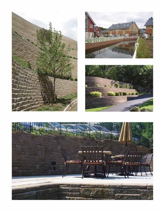
8 A Complete Family of Wall Products The Allan Block Collections give you a choice of styles to meet your site and design requirements. Use the basic gravity wall system for smaller wall projects. For taller wall projects use geogrid to reinforce the wall, or consider optional techniques using masonry, nofines, rock bolts, soil nails, or earth anchors. AB Collection Classic Cut Style The AB Collection has been a favorite of wall builders for years and offers the perfect blend of performance and style with maximum performance. AB Europa Collection Old World Antique The AB Europa Collection captures the handlaid stone effect that brings old world charm and distinction to any project in beautiful marbled colors.


9 The Allan Block Collections offer a variety of sizes, weights, setbacks, and finishes to meet differing aesthetic and performance needs. Refer to the chart below or to our website to help make the right choice for your project. SYSTEM Style & Performance Name Setback Coverage Weight Approximate Dimensions Table 1.1 AB Stones 12 1 sq ft. approx. lbs 8 in. H x 12 in. D x 18 in. L Best Single Block Choice 11 blk per m 2 kg 200mm H x 00mm D x 0mm L AB Rocks 1 sq ft. approx. lbs 8 in. H x 12 in. D x 18 in. L 11 blk per m 2 kg 200mm H x 00mm D x 0mm L AB Three 1 sq ft. approx. lbs 8 in. H x 12 in. D x 18 in. L 11 blk per m 2 kg 200mm H x 00mm D x 0mm L AB Classic 1 sq ft. approx. lbs 8 in. H x 12 in. D x 18 in. L 11 blk per m 2 kg 200mm H x 00mm D x 0mm L AB COLLECTION AB Jumbo Jr 0. sq ft. approx. lbs 8 in. H x 9. in. D x 9 in. L 22 blk per m 2 1 kg 200mm H x 20mm D x 20mm L AB Lite Stone 0. sq ft. approx. lbs in. H x 12 in. D x 18 in. L 22 blk per m 2 1 kg 100mm H x 00mm D x 0mm L AB Junior Lite 0.2 sq ft. approx. 18 lbs in. H x 12 in. D x 9 in. L blk per m 2 8 kg 100mm H x 00mm D x 20mm Old World Antique Name Setback Coverage Weight Approximate Dimensions AB EUROPA COLLECTION AB Dover 1 sq ft. approx. 80 lbs 8 in. H x 10. in. D x 18 in. L 12 blk per m 2 kg 200mm H x 2mm D x 0mm L AB Palermo 0. sq ft. approx. lbs 8 in. H x 9. in. D x 9 in. L 22 blk per m 2 1 kg 200mm H x 20mm D x 20mm L AB Barcelona 0. sq ft. approx. 0 lbs in. H x 10. in. D x 18 in. L 22 blk per m 2 18 kg 100mm H x 2mm D x 0mm L AB Bordeaux 0.2 sq ft. approx. 20 lbs in. H x 10. in. D x 9 in. L blk per m 2 9 kg 100mm H x 2mm D x 20mm L Actual dimensions, weights and setbacks will vary by manufacturer. Check with your local Allan Block manufacturer for exact specifications and color availability. Caps and corner blocks are also available for each of the collections. Patterned Walls The design possibilities are endless. Use the blocks individually or blend them together to create AB Ashlar or AB Abbey Blend patterned walls. The interlocking blocks easily fit together without any materials or tools. AB Ashlar Blend from the AB Collection AB Abbey Blend from the AB Europa Collection 8


10 The Allan Block System Engineered For Simplicity Allan Block s builtin features make retaining walls easy to engineer and simple to build. These simple engineering features make the Allan Block Collections the most efficient and reliable products on the market. Mortarless Construction Mortarless technology works. Building flexible structures with interlocking drystacked materials provides superior performance over rigid construction techniques. Add the benefits inherent in a mortarless system site adaptability, installation by general laborers, lower cost and you have what we call the Allan Block Advantage. BuiltIn Engineering BuiltIn Interlock Every Allan Block is firmly locked in place by the patented front lip. No pins, no mortar, no fancy connectors. BuiltIn Setback The raised front lip automatically establishes the proper setback. Choose from 12,, or systems. BuiltIn Drainage The hollowcore design combines with mortarless construction to allow water to drain freely from behind the wall. Incidental water moves easily through a vertical drain that is formed by the layer of wall rock placed behind the block and in the block cores. The drystack construction technique allows the incidental water to escape by flowing around the blocks and out the wall face. This builtin drainage helps to eliminate water pressure. Please note that this area is not to be used as a primary water management element. Mortarless construction has been used for centuries. BuiltIn Interlock BuiltIn Setback BuiltIn Drainage 12º º º approximate setbacks 9


11 HollowCore System Allan Block s exclusive hollowcore product design provides many benefits over solid systems. Superior drainage. Faster drying in wet environments. Better resistance to freezethaw cycles. Improved efflorescence control. Easier handling, faster installation, lower labor costs. Blocktoblock interlock created from wall rock in the blocks. Lower production and freight costs. SYSTEM Table 1.2 Standard Product Specifications Compressive Strength 000 psi 20. MPA Absorption Northern Climates. lb/ft 120 kg/m Absorption Southern Climates 10 lb/ft 10 kg/m Unit Density Hollow 12 lb/ft 2002 kg/m Unit Shear Strength lb/ft 90 N/m Reference ASTM 12 10


12 Gravity Walls A retaining wall that relies solely on it s own weight to stand up is called a gravity wall. Allan Block combines the basic engineering principles of setback, leverage and total unit mass with simple mechanics to make highly stable gravity walls. Setback & Sliding Wedge Every retaining wall supports a wedge of soil. The wedge is defined as the soil which extends beyond the failure plane of the soil type present at the wall site, and can be calculated once the soil friction angle is known. As the setback of the wall increases, the size of the sliding wedge is reduced. This reduction lowers the pressure on the retaining wall. See references 1,, 1 Leverage and Total Unit Mass As the setback of a gravity wall increases, the leverage from course to course increases. This added leverage allows you to build taller walls before reinforcement is needed. With the hollow core design, Allan Block comes to the job site weighing less than solid, heavy block. Once the cores are filled, the Allan Block units develop the same unit mass as solid blocks. This mass combines with the setback to determine the maximum gravity wall heights. See Table 1.. See reference 1 Allan Block s 12 system can achieve wall heights up to. ft. (1. m) without reinforcement in good soils with a level slope above. Gravity Wall Heights Use the gravity wall chart to find the maximum height that can be built before reinforcement is required. The gravity wall heights shown do not account for seismic loading. Check with a local engineer for assistance if you are in a seismic area. See reference 1, Condition above retaining wall Level Surcharge 12 psf ( kpa) Slope :1 Table 1. Maximum Wall Heights AB Gravity Walls 1 Soil Type Friction Angle 12 AB Stones only of AB Collection AB and Europa Collections AB Three only of AB Collection Clay 2.2 ft 2. ft 2.0 ft 1.0 m 0.8 m 0.8 m Silty Sand 2.0 ft.0 ft.00 ft 1. m 1.1 m 0.9 m Sand/Gravel.0 ft.00 ft.0 ft 1. m 1.2 m 1.1 m Clay ft 1.2 ft 1.00 ft 0. m 0. m 0. m Silty Sand ft 1.0 ft 1.2 ft 0. m 0. m 0. m Sand/Gravel 2.0 ft 1. ft 1. ft 0.8 m 0. m 0. m Clay ft 2.00 ft 1. ft 0. m 0. m 0. m Silty Sand 2. ft.00 ft 2. ft 1.1 m 0.9 m 0.8 m Sand/Gravel.0 ft.0 ft.00 ft 1. m 1.1 m 0.9 m 11
 Sliding Resistance Bearing Capacity ( S ) = 000 lb/ft 2 (1,0 Pa) Wall Density ( w ) = 10 lb/ft (2,01 kg/m ) Soil Density ( S ) = 120 lb/ft (1,92 kg/m ) Factored Friction Angle ( w) = 0.")
13 Sample Calculation Analyze a gravity wall with the following site conditions: Soil Type = Mixed Silts ( ) = 0 Wall Height (H) =. ft (1.0 m) Batter = 12 Depth of Wall (d) = 0.9 ft (0. m) Sliding Resistance Bearing Capacity ( S ) = 000 lb/ft 2 (1,0 Pa) Wall Density ( w ) = 10 lb/ft (2,01 kg/m ) Soil Density ( S ) = 120 lb/ft (1,92 kg/m ) Factored Friction Angle ( w) = 0. Slope Above Wall (i) = 0 Surcharge = None SYSTEM F A = Active force on wall = 0. ( S ) (K A ) H 2 = 1 lb/ft (2,29 N/m) K A = Active pressure coefficient [ CSC ( ) SIN ( ) 2 (SIN ( + W )) 1/2 + (SIN ( + W) SIN ( i)) ] = 1/2 = SIN ( i) W = Total weight of wall = w (H) (d) = lb/ft (,9 N/m) F V = Vertical force on wall from retained soils = F A SIN ( W ) = lb/ft (8 N/m) F H = Horizontal force on wall from retained soils = F A COS ( W ) = 1 lb/ft (2,1 N/m) F R = Force resisting sliding = (W + F V ) TAN = 281 lb/ft (,10 N/m) Safety factor against sliding: SFS = F R = 281 lb/ft (,10 N/m) = OK F H 1 lb/ft (2,1 N/m) Overturning Resistance M O = Overturning moment = F H (0.) H = 18 ft. lb/ft ( Nm/m) M R = Moment resisting overturning = (W) [d/ (H) TAN (90 )] + (F V ) [ d + (0.) (H) TAN (90 )] = ft. lb/ft (1,9 Nm/m) Safety factor against overturning: SFO = M R = ft. lb/ft (1,9 Nm/m) = OK M o 18 ft. lb/ft ( Nm/m) See the Allan Block Engineering Manual for more information. Gravity Wall Analysis Bearing Capacity W = Pressure exerted on soil below base block = (W + F V ) / d = 8 lb/ft 2 (2,8 Pa) S = 000 lb/ft 2 (1,0 Pa) Safety factor against bearing failure: FSB = S =,000 lb/ft 2 (1,0 Pa) 8 lb/ft 2 (2,8 Pa) W = OK Before you analyze any retaining wall make sure you have an accurate picture of the job site conditions. Every retaining wall must be engineered to withstand the pressure from the soils and other loads behind and above them. Standard gravity wall analysis considers sliding, bearing and overturning forces. On sites with slopes and surcharges, a global stability check will also be necessary. Sliding Ability of the structure to overcome the horizontal force applied to the wall. Factor of safety = 1. Bearing Capacity Ability of the underlying soil to support the weight of the structure. Factor of safety = 2.0 Overturning Ability of the structure to overcome the overturning moment created by the rotational forces applied to the wall. Factor of safety = 1. OTHER CONSIDERATIONS: Slopes Surcharges Terraces Global Stability Ability of the internal strength of the soil to support the complete soil mass. Contact local design specialist for help in evaluating your site. See reference 1 12


14 Reinforced Soil Walls Concept When wall heights exceed those listed in the gravity wall chart on page 11, geogrid can be added to provide a stable wall condition. Layers of geogrid inserted between the blocks and extending behind the wall interlock with the surrounding soil to create a cohesive soil mass. This mass uses its own weight and internal shear strength to resist both the sliding and the overturning pressures from the soil being retained. The wall rock in the Allan Block cores provide a positive connection between the layers of geogrid and the Allan Block wall, locking the two systems together. The reinforced soil mass becomes the structure and the Allan Block wall becomes the facing. The specific location and embedment length of the grid layers depends upon the site conditions, wall heights and LongTerm Allowable Design Strength of the grid being used. See the approved plans for exact geogrid locations or consult with a local engineer. The Great Wall of China, dating back some 2,200 years, was built as a double sided retaining wall. The soil between the two walls was a mixture of clay and gravel reinforced with Tamarisk branches. Allan Block retaining walls employ old technology with new materials. Geogrids Geogrids are flexible, synthetic meshes which are manufactured specifically for slope stabilization and earth retention. These grids are available in a variety of materials, sizes and strengths. They can be made of high tensile strength plastics or woven polyester yarns and are typically packaged at the factory in rolls. The grids are rated by LongTerm Allowable Design Strength (LTADS) with values ranging from 00 to,000 pounds per linear foot (. kn/m to 8. kn/m). See reference 1 Positive Interlock Allan Block s gravel filled hollow core provides a multipoint interlock with the grid. As wall heights increase, our exclusive rocklock connection, combined with the weight of the Allan Block units, provides the best blocktogrid interlock of any system on the market. See the tech sheets on connection testing or the Seismic Testing Executive Summary for testing results on the rocklock connection. Connection strength testing has been done with our grid manufacturers for results see the AB Spec Book or AB Engineering Manual. See reference 1, 2,, 12 1


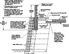
15 Analysis External Stability External stability exists when the entire wall system the Allan Block facing units and the reinforced soil mass act as a coherent structure to satisfy standard gravity wall analysis. Proper wall design must satisfy all four of the following considerations. SYSTEM Sliding Bearing Overturning Global Internal Stability Internal stability is the ability of the reinforcement combined with the internal strength of the soil to hold the soil mass together and work as a single unit. Internal Compound Stability Slip plane that runs through the retained and reinforced soil and wall facing. Grid Rupture Pullout Bulging Internal Compound Rupture occurs when excessive forces exceed the ultimate tensile strength of the geogrid. Increase grid strength or the number of grid layers See reference 1, 11, 1 Pullout results when grid layers are not embedded a sufficient distance beyond the failure plane. Increase embedment length Bulging occurs when horizontal forces between the geogrid layers causes localized rotation of the wall. Increase number of grid layers Internal Compound instability occurs when a slip arc passes through retained soil, reinforced soil, and facing. Increase length, strength, or decrease spacing of grid, use select infill material Design Considerations Grid strength Select the right strength grid for the job. Choose LTADS grids from 00 lb/ft to 000 lb/ft (. kn/m to 8. kn/m). Embedment length Grid length must extend far enough behind the wall to create a sufficient reinforced gravity mass. Typically a minimum of 0% of total wall height. Number of layers Install enough layers to adequately increase the internal strength of the soil mass and handle all applied loads. Spacing between layers Grid layers must be correctly spaced to distribute internal forces. Typically spaced on 1 in. (0 mm) centers. Connection strength Block and geogrid must work together to resist internal forces. AB Geogrid Wall Typical Section 1


16 Other Reinforcement Options Masonry Reinforcement Allan Block retaining walls can be reinforced with the same proven techniques used for conventional masonry walls. Allan Block masonry walls are useful on sites where geogrids are not feasible or cost effective because they rely on a reinforced footing and vertical pilasters to counteract lateral earth pressures. These walls combine the mortarless stability of an Allan Block wall with the tensile strength of the steel rods in pilasters and the stability of the footing. The design and construction of these walls meet all building code requirements, while factoring in the benefit of an inclined Allan Block wall. The specific design requirements depend on site and soil conditions, and wall heights. Typical Section See reference 10 When considering special applications, unusual job sites, or unique reinforcement requirements, contact the Allan Block Corporation for engineering and design support. The Allan Block Engineering Department provides assistance to engineering and design professionals worldwide. For additional information and case studies call Other System Options In addition to basic masonry wall systems, Allan Block can accommodate special reinforcement systems such as nofines concrete, rock bolts, earth anchors and soil nailing. Earth Anchor NoFines Concrete Soil Nailing 1
17 PLAN / DESIGN PLAN / DESIGN Plan and Design an Allan Block project. Develop a Plan 1 Design Evaluation 20 1

18 Plan Develop an accurate understanding of the job site before beginning any design, engineering, or construction on a project. Site Geometry Develop an accurate PLAN of existing physical features. Observe the soil type and condition, site geometry at the wall location and immediate surroundings. Note the natural drainage patterns. Identify all physical features surrounding the proposed wall location. Note key elevations, lot lines, utilities, structures, vegetation, etc. Conditions above and behind the wall will determine how high the wall can go before reinforcement is needed. Note the site geometry above and below the proposed wall location. Soils Soil conditions behind and below each retaining wall have a direct effect on the strength needed in that retaining wall. The pressure from behind the wall will vary substantially depending on the soil type. In general, a wall built in clay soils will require more reinforcement than a wall of the same height built in free draining sand or gravel soils. Check the soil type and conditions at the base of each wall for adequate bearing pressure. The soil below a wall needs to be strong enough to support the weight of the wall resting on it. When moisture is present, extra precautions may be required to provide a stable base. If the soils at the base of the wall have been disturbed i.e. excavated and replaced it is imperative that these soils are properly compacted before construction begins. It may be necessary to remove poorly compacted or soft, wet organic soils at the base and replace them with stable, wellcompacted soils prior to wall construction. See page 28 & Soils Table 2.1 Soil Friction Bearing Equivalent Type Angle Capacity Fluid Pressure Clay 2 2,00 lb/ft 2 0 lb/ft kPA.9kN/m Mixed Soils 2,00 lb/ft 2 lb/ft 1.80kPA.kN/m Sand/Gravel,000 lb/ft 2 0 lb/ft kPA.kN/m Use the soil classification chart above to identify the basic properties of the soil at the site. These soil properties are approximate. For a thorough soil analysis, have a qualified geotechnical engineer conduct a site inspection.
 to determine the water flow and volume.")


19 Water Management Make a careful observation of the general drainage patterns at the site. Note the amount of area above the wall which will shed surface runoff toward the wall. Note the type of surface (i.e., paved surfaces, sodded areas, etc.) to determine the water flow and volume. Note any concentrated sources of water flow such as runoff from parking lots, roof drains and scuppers, drainage swales, creek beds, ground water, etc. See page 0 & 1. Grading Develop a grading plan that routes water around the walls as much as the site will allow. Provide swales above and below the wall as required to accommodate water movement. Divert sources of concentrated water flow from the wall. Retaining wall designs must prevent the pooling of water above or below the wall. PLAN / DESIGN Drainage Proper drainage planning considers water flow and volume above, below, and behind the retaining wall. Most Allan Block gravity walls (lower unreinforced walls) will drain adequately on their own. If a large area sheds water to the wall (i.e., parking lot), added drainage will be necessary. Concentrated sources of water must be planned for and managed. Reinforced walls will need added drainage for the backfill zone and the wall base. Major wall structures, roadway and municipal projects, and walls built in extreme rainfall or wet environments will need a thorough hydrology analysis prior to construction. Surcharges Surcharges Any added weight above the wall is called a surcharge. Parking lots, swimming pools, and driveways are common surcharges. Light duty surcharges are designed at 12 psf ( kpa). Heavier commercial surcharges (like trucks), run 20 psf (12 kpa) and up. More concentrated line loads may also be a factor (such as building foundations). Engineering is required in each situation. 12 psf ( kpa) Light Vehicle 20 psf (12 kpa) Roadway See reference 1 18


20 Slopes Above Slopes Below Slopes Slopes are measured run to rise. A threetoone slope goes back and up 1. Slopes Above Slopes above the wall add more pressure and will require more mass to resist movement. Engineering is required. Slopes Below Slopes below the wall may create an unstable foundation. Check with local building codes for length of bench that may be required. Engineering is required. Setback Setback The amount the wall leans into the hill is called setback. AB units come in multiple setbacks. Bigger setbacks provide better leverage and require less reinforcement. For taller walls use a story pole and level to check for proper setback. Setbacks increase when walls are built with radii. Comply with construction tolerances which are found in the AB Spec Book or approved construction plans. Note: Walls designed with a 12 setback require more space than or systems, but will be more stable. You may give up ground but the final factors of safety are higher. Global Stability Global stability is an engineering analysis of the overall balance of a slope or hillside. Walls built on hillsides may affect this balance and stability. Cuts into a hillside will steepen the effective slope and shift the balance of the hill, thereby reducing stability. Walls built on top of slopes have the same effect. Engineering is required. Setback AB Stones only of the AB Collection AB and AB Europa Collection (excluding AB Stones & AB Three) AB Three only of the AB Collection Global Stability Table 2.2 AB Setback Chart Wall Height ft ft 8 ft 10 ft 1.2 m 1.8 m 2. m.0 m 10.0 in 1.0 in 20.0 in 2.0 in 2 mm 80 mm 10 mm mm.0 in.0 in 10.0 in 12. in 12 mm 190 mm 2 mm 20 mm 2. in. in.0 in.2 in mm 9 mm 12 mm 10 mm What to consider when assessing global stability: Surcharges / Tiered Walls Slopes Soil Properties Water See reference 1, 1 19


21 Design The design process for a segmental retaining wall typically has a Wall Design Engineer or Site Civil Engineer responsible for the wall design envelope. Geotechnical engineers should be hired to evaluate the overall stability of the site. For information into the basic concepts behind an Allan Block retaining wall design see page 19 of the AB Spec Book. Proper retaining wall design requires evaluation of the following: 1. Select the wall location Minimize soil excavation and backfill. Optimize grading and drainage patterns. Consider existing site features. 2. Determine wall height and geometry Calculate the wall height at its tallest position. Identify slopes above and below the wall. Evaluate surcharges from vehicular or construction traffic. Select the appropriate wall batter or setback.. Evaluate structural requirements Check the gravity wall table on page 11 for reinforcement requirements. If geogrid is required, see pages for approximate grid length. For projects that fall beyond the scope of the tables in this manual, refer to the Allan Block Engineering Manual and contact a qualified engineer.. Calculate the total wall structure Use table 2.2 to calculate the total wall setback. Add the required grid lengths to determine total wall envelope. Cross check the total wall envelope with available space at wall site. Note: For more information see page 11 & 12 of the AB Spec Book. PLAN / DESIGN Material and Site Checklist Prior to Construction Building a reinforced retaining wall requires advanced planning and careful layout at the job site. Check Your Materials Cross check the block delivered for color, style and setback, and confirm it matches the AB unit specified on the approved plans. Cross check the geogrid delivered for strength, weight, roll size, strength direction and manufacturer, and confirm it matches the grid specified on the engineered plans. Delivery and Storage Lay out a storage area for the block, geogrid reinforcement, and wall rock. Store blocks on wood pallets and keep the geogrid dry, covered and clean. Protect the materials from damage or from coming in contact with mud, wet concrete, and other contaminating materials. Damaged material should not be incorporated in the project. 20

22 Wall Rock The proper placement of the wall rock serves several purposes: Locks the block and grid together to form a RockLock connection. Increases the overall weight of each AB Unit, increasing structural stability. Facilitates the compaction process in and around the blocks. Prevents settlement directly behind the block, which minimizes additional forces on the grid. Backfill Soils Onsite soils can be used for backfill around the geogrid reinforcement only if they meet or exceed the design specifications in the approved plans. Heavy expansive clays or organic soils shall not be used in the reinforced zone. Where additional fill is required, the contractor shall submit a sample to the wall design engineer or the onsite soils engineer for compliance with the approved plans. Foundation Soil Preparation Foundation soil shall be excavated as dimensioned on the plans and compacted to a minimum of 9% of Standard Proctor prior to placement of the base material. Foundation soil shall be examined by the onsite soils engineer to ensure that the actual foundation soil strength meets or exceeds assumed design strength. Soil not meeting the required properties shall be removed and replaced with acceptable material. Geogrid Layout The geogrid reinforcement design will determine the depth of the reinforced zone and the excavation required. Before construction begins, verify top of wall (TW) and bottom of wall (BW) locations. Check for buried utilities and other obstructions in the reinforced zone. Wall Elevation to identify grid locations Wall Rock can be used for the base material, within the AB Block cavities and behind the block. Wall Rock must be compactible aggregate ranging in size from 0.2 in. to 1. in. ( mm 8 mm) with no more than 10% passing the #200 sieve with a minimum density of 120 lbs/ft (1,92 kg/m ). There needs to be a balanced mix of the sizes to achieve good compaction. Refer to the AB Engineering Manual, AB Spec Book, AB Seismic Executive Summary, and the AB Walls 200 Software for more detailed information. For design assistance contact the AB Engineering Department or go to. Wall Cross Section 21
23 BUILD BUILD Installation details for Gravity or Reinforced Allan Block retaining walls. Gravity Wall Construction 2 Reinforced Wall Construction 2 Working with Soils 28 Compaction 29 Water Management 0 22
 wide and 12 in. (00 mm) deep. Remove unsuitable soils and replace with compactible materials.")
 of wall rock in the base trench and rake smooth. Compact and level base material.")
 tall or are constructed in silty or clay soils.")
 behind the wall with wall rock.")
24 Gravity Wall Construction Building Gravity Walls Gravity Wall Typical Cross Section Step 1: Site Prep and Excavation Remove surface vegetation and organic soils. Per the approved plan, excavate base trench a minimum of 2 in. (10 mm) wide and 12 in. (00 mm) deep. Remove unsuitable soils and replace with compactible materials. Buried block should be a minimum of in. (10 mm). Check plans to see how much buried block is required. Compact and level trench. Step 2: Install Base Material Per the approved plans, place a minimum of in. (10 mm) of wall rock in the base trench and rake smooth. Compact and level base material. Site Soils Engineer should verify that a proper base is established. Step : Install Base Course Begin at the lowest wall elevation. Place AB units on base material, check and adjust for level and alignment of each unit. Drain pipe is required for walls over ft. (1.2 m) tall or are constructed in silty or clay soils. See approved plans for location and specifications. Refer to page 9 for details on an alternate drain location. Step : Install Wall Rock and Backfill Materials Fill the AB hollow cores and a minimum of 12 in. (00 mm) behind the wall with wall rock. Use approved soils to backfill behind the wall rock and in front of the base course. Use a plate compactor to consolidate the area behind the block. Compact in lifts of 8 in. (200 mm) or less. Step : Install Additional Courses Remove all excess material from the top surface of AB units. This can be done when installing the next course of block, by sliding the block into place. Stack the next course of blocks so that the vertical seams are offset from the blocks below by at least in. ( mm) or 1/ the length of the block. Check and adjust for level, alignment and the wall batter as the wall stacks up. Fill the block cores and behind with wall rock then place approved soils as described in Step. From course 2 and above use a plate compactor to compact directly on the blocks as well as the area behind the blocks. Compact in lifts of 8 in. (200 mm) or less. Complete wall to required height. See page 9 for information on wall ending options. Use 8 in. (200 mm) of impermeable fill on the last lift to finish off wall. See page 2 for more detailed information on these installation steps. Gravity Wall Base Course Cross Section. Install base material, level and compact. Level Level String Line Compact base material Adjust with a dead blow hammer Level blocks, adjust where needed. 2
 lifts or less.")
 wide and in.")

25 Reinforced Wall Construction Step 1: Site Prep and Excavation Foundation soils at the bottom of the base trench must be firm and solid. If the soils are made up of heavy clay or wet soils, or the areas have been previously excavated, remove entire material and replace with granular base, compacting in 8 in. (200 mm) lifts or less. Remove all surface vegetation and organic soils. This material should not be used as backfill. Excavate behind the wall to accommodate the design length of the geogrid. Refer to the approved plans for exact length. Excavate base trench at the wall location. Dig the trench, per the approved plans, a minimum of 2 in. (10 mm) wide and in. (10 mm) deep plus the required amount to accommodate the buried block. Buried block should be a minimum of in. (10 mm) or 1 in. (2 mm) for each 1 ft. (00 mm) of wall height. See approved plans for exact amount needed. Compact and level base trench to 9% of Standard Proctor. Reinforced Wall Base Course Cross Section. Step 2: Install Base Material The base material can be any compactible granular material. Allan Block recommends a wellgraded aggregate, with a balanced mix of grain sizes, ranging from 0.2 in. to 1. in. ( mm to 8 mm) diameter. Per the approved plans, place drain pipe at the back of the trench the length of the wall. The drain pipe will need to be vented to daylight or to a storm sewer system. See approved plans for location and specifications. Per the approved plan, place a minimum of in. (10 mm) of base material in the base trench and rake smooth. Compact with a mechanical plate compactor. Check the entire length for level, and adjust as needed. Level Compact base material Install and compact base material. BUILD Typical Reinforced Wall Cross Section Reinforced Wall Structure Reinforced Zone The reinforced zone is located directly behind the block in two sections, the consolidation and the compaction zone. Both zones require compacting in maximum lifts of 8 in. (200 mm), to 9% Standard Proctor. Refer to the specifications in the approved plan for compaction requirements in these zones for each project. Consolidation Zone The consolidation zone runs from the back of the block back ft. (0.9 m) into the infill soil. Only mechanical plate compaction equipment shall be allowed within the consolidation zone. Compaction Zone The compaction zone runs from the back of the consolidation zone to the cut in the slope. Heavier compaction equipment can be used in this zone provided no sudden braking or sharp turning occurs. 2

 of coarse sand under the units.")
 behind the block with wall rock. A compactible aggregate ranging in size from 0.2 in. to 1.")
26 Reinforced Wall Construction Step : Install Base Course Begin at the lowest wall elevation. Place all units top side up with the raised front lip facing up and forward on the base material. Check and adjust for level and alignment of all AB units. Check block for level frequently from sidetoside and fronttoback. Verify the proper position of all AB units by examining a string line across the back of the blocks or by sighting down the back of the raised front lip. Make minor adjustments by tapping the AB units with a dead blow hammer or by placing up to 0. in. (1 mm) of coarse sand under the units. Irregularities in the base course become larger as the wall stacks up. Careful attention to a straight and level base course will ensure a quality finished wall. Step : Install Wall Rock and Backfill Material Fill the hollow cores of the base course and 12 in. (00 mm) behind the block with wall rock. A compactible aggregate ranging in size from 0.2 in. to 1. in. ( mm to 8 mm) in diameter, and containing less than 10% fines is recommended. Use approved infill soils to backfill behind the wall rock and in front of the base course. Step : Compact Compaction of the material behind the block is critical for a quality wall. Use a mechanical plate compactor to consolidate the wall rock, then compact the backfill material immediately behind the block. Compact in a path parallel to the wall, working from the back of the block to the back of the backfill material See Page 29 for additional details on compaction. Check the base course for level and adjust as necessary. All backfill soils must be compacted to a minimum 9% Standard Proctor. Use equipment appropriate for the soil being compacted. Remove all excess material from the top surface of all AB units. This prepares a smooth surface for placement of the next course. This can be assisted when installing the next course of block, by sliding the block into place. Every course after the first course requires compaction starting on the block. String line Infill soils Level Install base course. Install wall rock. Wall rock Adjust with a dead blow hammer Fill void in front of block Compact parallel to wall Compact wall rock and backfill soils. Stepping Up The Wall Base Walls built on a sloping grade require a stepped base. Begin excavation at the lowest point and dig a level trench into the slope until it is deep enough to accommodate the base material and one entire block. At this point step up the height of one block, and begin a new section of base trench. Continue to step up as needed to top of slope. Always bury at least one full unit at each step. 2


27 Reinforced Wall Construction Step : Install Geogrid Refer to the plans for placement of grid; this example starts on the base course. Cut sections of geogrid to specified lengths. Check manufacturer s grid specifications for strength, and roll or machine direction. Refer to the approved plans for exact size and location. Install the layer of geogrid by placing the cut edge to the back of the raised front lip and roll the layer out to the back of the excavation area. The excavation area must be fully compacted and level. Stack the next course of block on top of the geogrid, so that the blocks are offset from the blocks below. Each new course should be positioned so that the vertical seams are offset by at least in. ( mm) and are tight against the front edge of the units below. Perfect running bond is not required. Sight down the wall line to check for a straight wall. Blocks may be adjusted slightly to form straight lines or smooth flowing curves. Pull on the back of the grid to remove any slack. Stake in place before installing wall rock and approved infill soils. Pull back geogrid and stake in place Place cut edge of grid tight against front lip Install geogrid, stake in place. Set second course on top of geogrid BUILD Working With Geogrid Geogrid typically comes in large rolls up to 1 ft ( m) wide and 20 ft ( m) in length. These grids also come in a variety of weights and strengths. Taller walls often require heavier strength grids, especially in the bottom portions of the wall. It is critical that the correct grid is installed in the wall. Check the engineered plans and specifications. Most grids are strongest along the roll or machine direction. Reinforced grid designs require that all grids are placed with the machine direction running from the face of the wall towards the back of the excavation area. See page 2 for information on using grid with corners and curves. Machine or roll direction Install geogrid with the machine or roll direction running from the block back into the reinforced zone. Front of wall Use a pair of grid stands to help measure and cut geogrid to required lengths. Machine or roll direction 2

, this time starting on the block and working in a path that runs parallel to the block towards the back of the reinforced zone.")

28 Reinforced Wall Construction Step : Backfill and Compact Install wall rock in block cores and 12 in. (00 mm) behind wall. Use approved infill soils to backfill behind the wall rock in the reinforced zone. All wall rock and infill soils within ft. (0.9 m) of the wall must be properly compacted using a mechanical plate compactor. Compact in maximum 8 inch lifts (200 mm), this time starting on the block and working in a path that runs parallel to the block towards the back of the reinforced zone. Compact all materials to a minimum 9% Standard Proctor. Never operate compaction equipment directly on geogrid. All heavy equipment must be kept at least feet (0.9 m) from the back of the wall. Wall designs typically do not account for surcharges from heavy compaction equipment. Even a properly installed and compacted wall will rotate forward when extreme surcharges from heavy equipment are applied to the top of the wall during construction and final grading. Check and adjust for level, alignment and the wall batter as the wall stacks up. It is acceptable to shim under blocks to compensate for a build up of tolerances or an out of level base condition. Asphalt shingles or geogrid work well when shims are required. The maximum allowable shim thickness per course is 1/8 in. ( mm). Remove all excess wall rock and ridges or slag material from the top surface of all AB units. This prepares a smooth surface for placement of the next course. Plate compactors operated on top of the block will remove most slag material and prep the block for the next course. When installing the next course of block, sliding the block into place will also remove any slag material. Compact in 8 in. (200 mm) lifts Compact in 8 in. (200 mm) lifts. Keep heavy equipment away from the back of the block. Sight down edge Keep heavy equipment ft. (0.9 m) from back of block Step 8: Install Additional Courses Repeat steps & to complete wall to height required, installing grid where needed per the approved plans. Use 8 in. (200 mm) of impermeable fill on the last lift to finish off wall. See page 9 for information on ending and topping off the wall. For information on Allowable Construction Tolerances see the AB Spec Book, page 20. Install blocks tight against blocks below Install additional courses. Seams at in. ( mm) minimum offset 2

29 Working with Soils The soils used below and behind the wall are a critical part of the total wall structure. A reinforced retaining wall is a structure containing three basic building materials the block facing, the synthetic geogrid reinforcing materials, and the infill materials surrounding the geogrid layers. Soils Understanding the properties and characteristics of soils is key to building better walls. Different soil types will dictate the amount of time needed for compaction, the amount of reinforcement required, and potentially the cost of the wall. Check the onsite soils carefully before beginning, and get a written identification of the soil type. A soils report from a local engineer will be required before a design and/or permit is issued for most walls above ft. (1.2 m). Table.1 provides general classification of soils. Soil Selection If the onsite soils are of a very low quality, you should remove and replace them with better backfill material in the reinforced zone and the foundation area. The cost of removal will be offset by reduced reinforcement, faster compaction, and better longterm performance. In the reinforced zone, the type of soil used will determine the amount of grid reinforcement needed. Heavy clays and organic soils are both unsuitable in the reinforced zone. Generally, any soil with a friction angle lower than 2 or a plasticity index (PI) of greater than 20 should be removed and replaced. Soils with friction angles between 2 and 1 will require additional care, and attention to water management when placed and compacted. This will include extra inspections by an onsite engineer. You must use infill soils that meet or exceed those specified in the engineered specifications and drawings. Have the soils tested before placing and compacting. Typical Friction Angle and Soil Unit Weights Compacted to 9% Standard Proctor Soil Type Soil Friction Angle Table.1 Soil Unit Weight Crushed stone, gravel Clean sands Silty sands/sandy silt Sandy clay Other soils Determined by testing BUILD 28


30 Compaction Proper placement and compaction of the infill soils are critical. Compaction is often measured as a percentage of optimum consolidation of material being utilized. Foundation and infill soils require compaction to 9% of Standard Proctor, or 9% of the soil's maximum density. Local geotechnical and civil engineers are trained to test and measure compaction densities. Onsite testing should be part of the wall project and included in the bid documents. Obtaining the optimum moisture content will ensure that the maximum density can be achieved. Soil that is too dry or too wet will not reach 9% of Standard Proctor. The most important step in getting proper compaction is the placement of the soil in "lifts". Compacting in lifts, or layers, of less than 8 in. (200 mm) will facilitate quality compaction. Compaction equipment must be sized according to the type of material being compacted. Placement and compaction in lifts that exceed 8 in. (200 mm) will result in less than adequate soil strength. Consult with a local equipment supplier to ensure that proper compaction equipment is used. Always backfill and compact after each course of block is placed. The consolidation zone runs from the back of the block back ft. (0.9 m) into the infill soil. Only walk behind mechanical plate compaction equipment shall be allowed within the consolidation zone. A minimum of two passes with a walk behind plate compactor are required. Continue compaction process until proper compaction is achieved, starting on top of the block and compacting in paths that run parallel with the wall to the back of the consolidation zone. Some applications require higher levels of compaction in the consolidation zone. Examples of these include additional walls or structures located within ft (0.9 m) of the back of the wall. Higher levels of compaction can be achieved within the consolidation zone by decreasing the lifts to in. (100 mm) and compacting with walk behind compaction equipment, starting at the wall facing and running in paths that run parallel to the wall. Compacting in smaller lifts will achieve higher compaction levels and will not place lateral loads on the wall facing. Multiple passes of the compaction equipment will be required. Higher compaction levels reduce settlement over time. Correct Compaction Process 29


31 Water Management The design and performance of most retaining walls are based on keeping the reinforced zone relatively dry. To ensure that wall structures perform, the construction of the wall and layout of the site must be based on maintaining a soil moisture content that is relatively low. Relatively low equates to the moisture content required to achieve desired compaction. Site civil engineering firms utilize a thorough understanding of the site to determine where water will come from and how it will be properly managed. Throughout their design process, sources of water are taken into account to handle above and below grade concentrations of water. Contractors must understand the intent of the approved site plans and what will be required to protect the area impacted by the wall construction. Temporary berms may be required to direct water away from construction sites. Allan Block walls may be designed with an array of details to ensure that the wall and reinforced soil structure remain free of excess moisture. Basic design details mandate toe drains for all walls over ft. (1.2 m) in height, with slopes, or other structures above the wall. Once geogrid is introduced into the design, heel drains are also incorporated. In all cases wall rock is located within the cores of the block and a minimum of 12 in. (00 mm) behind the block. These three details are designed to remove incidental water within their respective locations and are not meant as primary drainage paths for above or below grade water management. Refer to your approved plans or the AB Spec Book for specific information on these items. Typical Drain Drains must be vented to daylight or connected to a storm sewer system. All drain pipes must be protected from migration of fine material. Refer to approved plans for construction details. BUILD See page 9 for a cross section drawing of this drain. 0


32 Grading During wall layout it is important to evaluate the entire site to determine if water will drain into the area where the walls will be constructed. Using simple berms and swales to divert the water around the wall can be easily done. Since walls are often built before the site is completely graded to its final configuration, temporary grading must be in place to ensure water will not be draining towards the construction area. Contact the local engineer of record and the site civil engineer for directions prior to proceeding with construction of the wall. Ground Water Ground water can be defined as water that occurs within the soil. Sources include surface infiltration, water table fluctuation and layers of permeable soils. Ground water movement must be prevented from coming in contact with the retaining wall structure, including the reinforced soil mass. Construction details to prevent subsurface water from coming in contact with the retaining wall structure should be defined on the approved plans. Use blanket and chimney drains to intercept ground water from potentially infiltrating the reinforced mass. When ground water is encountered during construction work with the engineer of record to ensure that the water has been accounted for in the design. Extra care must be employed to prevent water from entering the reinforced zone when nonpermeable infill soils are used in wall construction. Drain pipes used in toe or heel drain applications must be properly vented a minimum of every 0 ft (1 m). Methods to accomplish this include having drain pipes draining into the storm sewer system or vented to a lower elevation on the site. See approved plans for locations. When venting to a lower elevation, it is important that all drain locations are properly marked during the construction phase and protected during and after the completion of the project to ensure that the drain pipe is not damaged or plugged. Rodent screens and concrete collars are examples of details employed to allow for water to flow through the outlet pipes and keep the pathway clear of debris. If details are not identified on the plans, request guidance from the local engineer or the site civil engineer. Concentrated Water Sources Prior to constructing the wall, review drainage plans and details with the general contractor or site civil engineer to identify all potential sources of concentrated water. Examples that must be accounted for are: Below grade storm sewer pipes Water lines, mains or fire hydrants Grading of site Parking lots Catch basin to storm sewer system Roof down spouts Slopes above walls Chimney Drain Blanket Drain Vent Drain Pipe Option 1
33 BUILD PATTERNED WALLS Installation details for building patterned Allan Block retaining walls. Wall Patterns Patterned Wall Construction Patterned Wall Construction Tips BUILD PATTERNED WALLS 2
 tall. Random patterns used on a reinforced wall require a level surface every 2 or courses for proper installation of geogrid.")
34 Wall Patterns All of the Allan Block Collections can be used to create a variety of preset and random patterns. A preset pattern is repeated every two or three courses of block. A single course consists of a full size block, approx 8 in. (200 mm) tall. Random patterns used on a reinforced wall require a level surface every 2 or courses for proper installation of geogrid. See the approved plans for which layers the geogrid reinforcement will be required. Note: Patterned walls will have a setback. Walls with curves should always use the 2 course pattern to minimize cutting and fitting. The base course needs to be a full course of full size blocks. For each 10 ft. ( m) length you will need full size blocks. Standard Patterns Uses all blocks in the collections Two Course Pattern 1 in. (0 mm) Approx. 10 ft. ( m) Approx. AB Collection Blocks Required AB Classic or AB Stones AB Jumbo Junior 8 AB Lite Stone 8 AB Junior Lite* AB Europa Collection Blocks Required AB Dover AB Palermo 8 AB Barcelona 8 AB Bordeaux Three Course Pattern 2 in. (10 mm) Approx. 10 ft. ( m) Approx. AB Collection Blocks Required 10 AB Classic or AB Stones 10 AB Jumbo Junior 10 AB Lite Stone AB Junior Lite* * Note: In the AB Collection, if the AB Junior Lite is not available an AB Lite Stone will need to cut in half. See page for more information. AB Europa Collection Blocks Required 10 AB Dover 10 AB Palermo 10 AB Barcelona AB Bordeaux Lite Patterns Uses only the smaller blocks in the collections Two Course Pattern 1 in. (0 mm) Approx. 10 ft. ( m) Approx. AB Collection Blocks Required AB Jumbo Junior 1 AB Lite Stone 12 AB Junior Lite* AB Europa Collection Blocks Required AB Palermo 1 AB Barcelona 12 AB Bordeaux Three Course Pattern 2 in. (10 mm) Approx. 10 ft. ( m) Approx. AB Collection Blocks Required 1 AB Jumbo Junior 19 AB Lite Stone 18 AB Junior Lite* AB Europa Collection Blocks Required 1 AB Palermo 19 AB Barcelona 18 AB Bordeaux Note: Maximum recommended wall height for Lite Patterns is ft. (1.8 m). For more information see the Allan Block Patterns document available at
 Site prep and excavation, 2) Install base material, ) Install base course ) Install wall rock and backfill materials, geogrid if necessary, and ) Compact.")


 behind the blocks. Compact using a shovel handle inside the cores.")
35 Patterned Wall Construction Step 1: Excavate and Install Base Course Refer to page 2 for a detailed description on how to install the base course. Basic steps include: 1) Site prep and excavation, 2) Install base material, ) Install base course ) Install wall rock and backfill materials, geogrid if necessary, and ) Compact. Note: Fullsized blocks should always be used for the base course. This will speed the leveling and installation of the first course. Install base course with full size units and compact Step 2: Install Geogrid Refer to the plans for placement of grid; this example requires grid on top of the base course. Remove all excess material and slag from the top surface of the base course. This prepares a smooth surface for placement of the geogrid and the next course of blocks. Cut sections of geogrid to specified lengths. Check manufacturer s grid specifications for strength and roll or machine direction. Refer to the approved plans for exact size and location. Install the layer of geogrid by placing the cut edge up to the back of the raised front lip and roll the layer out to the back of the excavation area to the length specified in the approved plans. Step : Install the MultipleCourse Pattern The example shown here uses a 2 course pattern. Check the approved plans to determine the best pattern option for the project. See page for more information on patterns. Stack the first course of the pattern on top of the geogrid and the base course. Check blocks for level, and make adjustments as needed. Pull on the back of the geogrid to remove any slack. Stake geogrid in place. Install wall rock in the block cores and 12 in. (00 mm) behind the blocks. Compact using a shovel handle inside the cores. Check blocks for level. See below for more information on compaction in the block cores. Compaction on Patterned Walls Install base course and compact. Install geogrid Stake grid in place Install Geogrid Stack first course of pattern and backfill wall rock in block cores. Typical Reinforced Patterned Wall First course of the pattern BUILD PATTERNED WALLS Compaction in the block cores needs to be done regularly when working with patterned walls. This can be done by using the end of a shovel to compact the wall rock, adding additional rock if necessary. At each 8 in. (200 mm) lift, compact the block cores with the end of a shovel, and the area directly behind the block with a plate compactor per the procedures described in this manual. At the conclusion of each pattern, the top of the wall will be level. Run the plate compactor over the top of the blocks to consolidate the wall rock. Place grid if required, and begin the next pattern.
 before compacting. The top of the blocks will not always match up with each lift of soil.")


36 Patterned Wall Construction Use approved infill soils to backfill behind the wall rock in the reinforced zone. The height of the wall rock and backfill material cannot exceed 8 in. (200 mm) before compacting. The top of the blocks will not always match up with each lift of soil. Using a mechanical plate compactor, compact the wall rock and infill materials behind the wall in maximum 8 in. (200 mm) lifts. Compact immediately behind the wall in a path parallel to the wall, working from the back of the wall to the back of the excavated area. Compact to a minimum of 9% Standard Proctor. Check blocks for level. and then install the remainder of the 2 course pattern. Install wall rock in the block cores and behind the blocks as before. Use approved infill soils to backfill behind wall rock. Check blocks for level and for batter. With the first multiplecourse pattern completed, use a plate compactor to compact the wall rock in the block cores and the wall rock behind the blocks. The first pass of the plate compactor should be directly over the top of the block cores. After running the plate compactor on top of the blocks and wall rock, compact the infill material immediately behind the wall. Compact in a path parallel to the wall, working from the front of the wall to the back of the infill material. Compact to a minimum of 9% Standard Proctor. Check and adjust for level and alignment and wall batter as the wall stacks up. It is acceptable to shim under blocks to compensate for a build up of tolerances or an out of level base condition. Asphalt shingles or geogrid work well when shims are required. The maximum allowable shim thickness per course is 1/8 in. ( mm). Step : Install The Second MultipleCourse Pattern Refer to the approved plans to determine if geogrid reinforcement will be required on the next course of the pattern being used. Repeat Step 2 to install geogrid between the patterns when required per the approved plans. Repeat Step for each pattern being installed. Each additional pattern will need to be offset from the pattern below to avoid a repetitive look. Note: Keep all heavy equipment at least feet (0.9 m) away from the back of the wall. Step : Ending and Topping off Wall Completing a patterned wall is the same as for a standard wall. See page 9 for finishing details. The only requirement is that a multiple course pattern must be completed so that the top course of the blocks form a level surface. Use 8 in. (200 mm) of impermeable fill on the last lift to finish off wall. Compact behind the wall. Complete pattern and compact. Offset patterns Compact wall rock and backfill materials parallel to wall Compact on blocks first and then the wall rock and backfill materials when pattern completed Install geogrid and additional patterns.


37 Patterned Wall Construction Tips Reinforced Wall Construction For walls that require geogrid reinforcement, selection of which pattern to use is determined by the grid spacing shown on the approved plans. If grid is required every 2 courses, then use a 2 course pattern; if course grid spacing is required, use a course pattern. If building with a random pattern, the pattern must be leveled off at the appropriate courses to allow for the installation of geogrid on a flat surface. Ending Patterned Walls Ending Patterned Walls Patterned walls may be ended with step ups or turnins. When ending a patterned wall, discontinue the pattern and randomly adjust as necessary to meet the site conditions. See page 9 for more information on ending walls. Curves When building curves, the 2 course pattern is easier to work with than the course pattern. The course pattern will require more custom fitting or cutting of blocks to ensure a tight fit. Inside curved walls are easily constructed by maintaining a tight spacing at the front of the wall face. For tighter radii, it may be necessary to cut out parts of the bottom notch in order for the blocks to fit tightly together. See page 0. Outside curved walls The wall will tighten as the height increases. There are three methods to adjust for the tightening effect: On the first course of the pattern, open the spacing between blocks slightly so that the top course(s) of the pattern will need minimal cutting. Reduce the lengths of the blocks by shortening them, using a saw with a diamond blade. Remove parts of the bottom notch for the blocks to fit tightly together. See page 0. The best answer is to always use the 2 course pattern when building curves. BUILD PATTERNED WALLS Dash of Ashlar The AB Collections have been created in modular sizes to allow for easy construction of patterned walls. Selected areas of nonpatterned walls can also contain patterns. With the modular design, the blocks can be installed with ease.


38 Patterned Wall Construction Tips Corners Outside corners are easily built using AB Corner Blocks. Start at the corner and build the wall working out in both directions. When ending a patterned wall with a corner, use a random selection of blocks to transition from the patterned courses into the AB Corner Blocks. Note: Always start the base course at the lowest elevation, then beginning additional courses at the corner will minimize cutting. AB Corner Blocks Patterned Walls With Corners Random pattern 2 course pattern Inside corners are constructed in the same manner as for nonpatterned walls. Remove the top lip of the course where the walls intersect. See page. Grade Below grade 2 course pattern Stairs When building steps into patterned walls, use the fullsized AB Blocks for step blocks. See page for stair construction details. Patterned Walls With Stairs Stepups When building a wall always start the base course at the lowest elevation. See page 22 for more information on construction. Additional Construction Tips If an AB Junior Lite is needed and not available, an AB Lite Stones will need to be cut to produce 2 half lite blocks. Precut the desired number of blocks to speed installation. Offset each new pattern from the pattern below to maintain the random appearance. With walls that have numerous inside and outside curves, use a 2 course pattern to ease the installation process. Cutting A Block In Half

39 CONSTRUCTION DETAILS Expanded details on building with Allan Block. Finishing Walls 9 Curves 0 Curves with Geogrid 2 Corners Corners with Geogrid Stairs Terraces Design Details 9 Construction and Installation Checklist 1 Material Estimate Worksheet References Geogrid Estimating Charts CONSTRUCTION DETAILS 8


40 Finishing Walls Ending and Topping Off Walls Allan Block offers a great variety of finishing options for the wall. Mulches: Allan Block s patented raised front lip provides a builtin edging for landscape rock, mulch, grass or soil. AB Capstones: AB Capstones can be used to finish off the top of a wall. Use a high grade, waterproof construction adhesive to secure AB Capstones in place. See for information on cutting AB Capstones for curves or corners. Mulch Building Step Ups Walls with step ups can be easily finished by adding an additional capstone or a half high block, or turning the ends back into the hillside. For tips with patterned wall step ups, see page. For a gradual stepup, use additional capstones or halfhigh blocks. AB Capstones For a full course stepup, use the AB Corner Block. AB Capstones with step ups Excavate, backfill and compact for turnin Building TurnIns For a graceful, flowing end to the wall, curve the wall to create a plantable area that can soften the look of the wall. Flowing turnin of wall Building TurnIns When building a turnin, a base trench will need to be excavated, backfilled and compacted, the same as the base course of blocks. For a stepdown that doubles as a planter, turn the wall in 2 or blocks after the AB Corner Block. 9 Install blocks and compact turnin Proper backfilling and compaction is important, where the wall turns back into the slope. To ensure the turnin area doesn t settle differently than the rest of the wall, make sure the entire area below the new base is compacted thoroughly. For a natural flow into the landscape, curve the wall back into the hillside.

41 Construction Details Curves Building curved and serpentine walls is simple. AB's patented design allows for easy installation of both inside and outside curves. Most curves can be built with no cutting involved. Try to maintain an offset of the vertical seams by at least ¼ of the block length from the courses below. Cutting a block in half or using the half width blocks, will assist in creating a proper offset. Before beginning construction, review the plans and layout the wall to eliminate tight radii. More gentle sweeping curves produce more aesthetically pleasing walls. See page 1 for the radius chart. Use blocks with lower setbacks or half width blocks on curves for smoother transitions. Inside Curves To build a flowing inside curve, butt the block end to end to match the smooth curve required on the project. Try to keep spacing consistent between the backs of the blocks. Outside Curves To build smooth outside curves, remove one or both of the "wings" from the back of the blocks and tighten the radius of the curve. Break wings off by tapping on the back of the wing to obtain a clean break. Remove wings for outside curves Outside Curve Inside Curve Consistent spacing Keep the front of the block tight together. Cutting The Bottom Notch For Tighter Inside Curves Tighter Curves Using full size blocks in tight curves will create a gap between the courses. For cleaner lines, it may be necessary to remove parts of the bottom notch to fit the blocks closer together. Area of notch to remove on bottom of block Cutting The Bottom Notch For Tighter Outside Curves CONSTRUCTION DETAILS Area of notch to remove on bottom of block 0
, and 2. ft. (0.8 m) using the half width blocks.")

42 Working with Radii Refer to Table.1 to confirm that the AB product you are using will accommodate the desired wall radius. The tightest or smallest radius at the top of any AB wall using full size block is ft. (1.2 m), and 2. ft. (0.8 m) using the half width blocks. The final height of the wall will determine what the minimum radius at the base course must be. The wall creates a coning effect as it is stacked up, creating the need for a larger radius at the base course. Use the Radius Chart to determine what the radius of the base course of the wall needs to be, so the top course of the wall will not be less than ft. (1.2 m). Starting a Radius From the point of where the curve will start, measure straight back from the wall the required amount (shown in the Radius Chart) and drive a stake into the ground. This will be the center of the curve. Attach a string line to the stake the length of the radius and rotate it around to mark the location of the base course. Install the blocks with the front of the blocks lining up with the mark. Base Course Radius for an outside curve on a ft tall wall Center Stake Top course radius.0 ft (1.2 m) Base course radius.1 ft (1. m) AB Radius Chart for the Base Course Setback Wall Height Full Size Blocks Table.1 ft ft 8 ft 10 ft 1.2 m 1.8 m 2. m.0 m. ft.0 ft. ft. ft 1. m 1.2 m 1. m 1. m.1 ft. ft.9 ft. ft 1. m 1. m 1.8 m 1.9 m To transition the curve back into a straight wall or another curve, lay out the curve and the first couple blocks of the next section. Adjusting 1 or 2 of the blocks will help in the transition of the next section of wall. 12 Half Width Blocks. ft.0 ft. ft.0 ft 1. m 1.8 m 2.0 m 2.1 m 2 ft ft ft 0. m 1.2 m 1.8 m.0 ft. ft.8 ft 0.9 m 1.0 m 1.1 m Use this chart to find the minimum recommended radius at base of wall. For a smooth curve with less cutting, use our half width blocks to help build the curve. 1


43 Construction Details Curves with Geogrid Inside Curves Geogrid needs to have 100% coverage around an inside curve. To achieve this, additional layers need to be installed either above or below the course where the grid is required to fill voids that are created. Cut geogrid to required lengths per the approved plan. Lay out the primary geogrid around the curve butting front edges together. Make sure strength direction runs perpendicular to wall face. Mark the blocks or take note of the areas where there are voids in the grid placement. Place the filler piece of grid on the next course (or the course below) to cover the void left on the primary layer. Additional grid layer placed on next course to eliminate gaps from course below Top View Mark blocks Trim grid to fit curve Primary layer Outside Curves Cut geogrid to required lengths per the approved plans. Lay out the geogrid around the curve. Lift the section of grid that overlaps and place the fill material to separate. Grid layers need to be separated by a in. ( mm) layer of approved fill material. Never compact directly on the geogrid. Grid layers need to be separated by a in. ( mm) layer of approved fill. Lift the area of grid up and place in the fill material to separate the layers CONSTRUCTION DETAILS Trim grid to fit curve Top View Place soil between the layers 2

. Lay the modified block perpendicular to another AB unit.")
.")


 minimum overlap Start construction of all walls at the corner. This will keep the block alignment within the in. ( mm) overlap required.")

44 Construction Details Corners Inside Corners AB Blocks are easily modified to build inside corners. To construct an inside corner, you will remove part of the raised lip on one block on each course. Step 1 Step 2 Use a saw with a diamond blade or a chisel to remove half of the raised front lip. This allows the next course to be installed on a level surface (Step 1). Lay the modified block perpendicular to another AB unit. This creates the corner (STEP 1). On the next course, remove the opposite half of the lip of an AB unit and position it over the right angle corner (STEP 2). On each successive course, simply reverse the position of the modified block to obtain an interlocked corner. Remove notch to form corner Remove part of front lip so next course will seat properly Area of front lip removed Outside Corners AB Corner Blocks are used to build outside 90 corners. To construct an outside corner, you will use an AB Corner Block on every course, alternating a right and left hand corner for each course. Additional corner construction information can be found at. Blocks with part of lip removed in. ( mm) minimum overlap Start construction of all walls at the corner. This will keep the block alignment within the in. ( mm) overlap required. Place an AB Corner Block at the corner. Place AB Blocks to build the base course working out from the corner in both directions (Step 1). Level, backfill and compact. On the 2nd course place an alternating AB Corner Block. Again work out from the corner in both directions. Level, backfill and compact (Step 2). Repeat this procedure, alternating every other course with AB Corner Blocks. Leveling, backfilling, and compacting as the wall grows (Step ). Step 1 Step 2 Ensure base is level going both directions Altering AB Corner Blocks for Different Setbacks AB Corner Blocks are manufactured with a 12 setback. With some minor adjustments, the blocks can be modified to work with any setback. To modify the block for a setback, cut a notch on the short side of the block 0. in. (20 mm) deep. For a setback, make a horizontal cut 0. in. (20 mm) deep Step Remove this piece after cut is made
. Cut geogrid to required lengths per the approved plan. As a general rule the length of the geogrid needs to extend a minimum of 2% of the wall height past the end of the inside corner.")
 EXAMPLE:")
.")
45 Construction Details Corners with Geogrid Installing Geogrid on Inside 90 Corners On inside corners additional geogrid is required to extend past the end of the wall, 2% of the completed wall height (H/). Cut geogrid to required lengths per the approved plan. As a general rule the length of the geogrid needs to extend a minimum of 2% of the wall height past the end of the inside corner. Install the layer of geogrid with the geogrid extending past the inside corner. Alternate the next layer of geogrid to extend the past the inside corner in the opposite direction. Geogrid with Inside 90 Corners Location of 1st required layer of geogrid Machine or roll direction The length of geogrid that extends past the wall, 2% of the entire wall height (H/) EXAMPLE: Finished wall height is 12 ft. (. m), divide by which equals ft. (0.9 m). The length the grid will need to extend past the corner is ft. (0.9 m). Location of 2nd required layer of geogrid Machine or roll direction Installing Geogrid on Outside 90 Corners Each leg of the wall must be reinforced independent of adjacent wall sections. This will require placement of grid to go up or down a course at the corner. Geogrid with Outside 90 Corners Location and direction of 1st required layer of geogrid Machine or roll direction Cut geogrid to required lengths per the approved plans. Install geogrid to the outside corner with the roll direction running back into the excavated site. On the next course of block, lay the next layer of grid perpendicular to the previous layer. Machine or roll direction Location and direction of 2nd required layer of geogrid CONSTRUCTION DETAILS


 or less when able. Install blocks on the base material. Allow for a space of at least in.")

 to achieve better compaction when able.")
46 Construction Details Stairs Basic Stair Construction Always check local code requirements before building any type of stair application. The steps below are general guidelines for building stairways. By understanding the basic installation elements, stairways can be easily incorporated into the wall installation. Before excavation can begin, the rise and run of the stair treads must be determined and code requirements must be met. With that information, the entire base trench can then be excavated. Some examples of different stair tread options are illustrated below. Our example here uses a base trench of in. (10 mm) and a stair tread of AB Capstones and pavers. Excavate to the necessary depth and width for each stair riser and thoroughly compact the entire area to 9% Standard Proctor with a mechanical plate compactor. Check for level. Starting at the first step, fill the base trench with in. (10 mm) of wall rock. Rake smooth. Compact and check for level. Stairs need extra compaction to avoid any settling later. Better compaction is achieved by backfilling and compacting in in. lifts (100 mm) or less when able. Install blocks on the base material. Allow for a space of at least in. (10 mm) behind the blocks for wall rock. Adjust for level and alignment of each block as it s installed. Install wall rock in the block cores, fill any space in front of and behind the block. When backfilling behind the blocks, fill the entire area that was earlier excavated to create the base for the next stair riser. This should produce a level base for the next set of risers. We recommend backfilling and compacting behind the block in in. lifts (100 mm) to achieve better compaction when able. Rake wall rock smooth and compact with the first pass of the compactor directly on the tops of the block and then working in a path that runs parallel to the block. Compact to 9% Standard Proctor. Repeat this process for each additional course of steps needed. Excavate for stairs and compact. Install and level blocks on base material. Backfill block cores and behind block with wall rock. Compact. Install next stair course. Continue for each new stair. Stair Tread Options AB Capstones AB Capstone and Pavers Pavers Concrete


47 Stairs can be designed with flowing curves or straight lines. Curved sidewalls create a softer, natural look. Straight sidewalls and corners offer a crisp, traditional style; however they require AB Corner Blocks and take more time to build. Allan Block s patented front lip provides a builtin edging that works well when installing the stair tread material. Allan Block Capstones, pavers, poured concrete, crushed rock, mulches and flagstone are good stair tread examples. Ensure that stair treads are secured in place for safe use. Additional stair designs and technical information explaining the construction process is available on our website at or from your local Allan Block representative. Remember to always check with the local codes before construction. How Many Steps? To find the number of steps needed, measure the total rise of your slope in inches (mm) and divide by 8 in. (200 mm) which is the height of a step. CONSTRUCTION DETAILS Rise 8 in. (1220 mm) 8 in. 8 in. = steps


48 Construction Details Terraces It is often more aesthetically pleasing to replace one large retaining wall with two or more smaller terraced walls. Terraced walls can act as surcharges and may create global instability, therefore reinforcement may be necessary. Always check with a local qualified engineer when building terraces. Walls perform independently and may not need engineering when the distance between gravity walls is at least two times the height of the lower wall, and the height of the upper wall is equal to or less than the height of the lower wall. Walls that must be evaluated by an engineer are any walls needing geogrid reinforcement, walls closer than two times the height of the lower wall, walls with more than two terraces, and terraced walls with any structures above. Terraced walls that do not perform independently must also be evaluated for global stability, and the lower walls must be designed to resist the load of the upper walls. Terraces
, or retention ponds are considered water applications.")


49 Water Applications Retaining walls constructed in conditions where there is moving water (streams), standing water with wave action (lakes), or retention ponds are considered water applications. Water applications must be evaluated and designed to fit the unique characteristics of the site. Consult with a local qualified engineer for design assistance. Water Application Fences/GuideRails There are several options for installing fences and guide rails on top of an Allan Block wall. The structure and wind loads of the materials used will determine the placement of the fence relative to the AB wall and if additional reinforcement is required. Refer to the approved plans for construction details. Lighting Allan Block s hollow core design makes it easy to install lighting. Cut a hole in the location where the light will be to accommodate the wiring and attachment of the light to wall face. Carefully follow the manufacturer s instructions for lighting and electrical installation, as various fixtures may be assembled differently. CONSTRUCTION DETAILS 8


50 Design Details All drawings are for information only and not for construction. See the approved plans for exact details or contact the local engineer of record for written guidance. Typical Reinforced Wall Application Typical Gravity Wall Application Typical Water Application Swales Chimney Drain Alternate Drain 9


51 Wind Bearing Fence or Railing, Option 1 Wind Bearing Fence or Railing, Option 2 NonWind Bearing Fence or Railing Double Wall Parapet Impact Barrier Non Impact Rail CONSTRUCTION DETAILS 0

52 Construction and Installation Checklist To ensure that the basics of the retaining wall project are covered, use the following construction and inspection checklist. For a thorough procedure use this list as a guide to prepare your project specific checklist and to review the most common points. It may also be used during the bidding process or a preconstruction meeting to ensure that all special provisions are complied with. Always check the local building codes, document any changes to the plan in writing, and notify the wall design engineer with any concerns on water management. Review wall design plans for: A. Compliance of site to latest site plan Does the site plan and wall layout coincide with current site conditions? Have all slopes above and below the walls been taken into account on the plans? Do the section drawings match the topography of the jobsite? Have site utilities been accounted for? Are there any recommendations for changes to the site plans to accomodate the wall? B. Review of reported soil conditions with onsite soils engineer Are onsite soils consistent with soil parameters used in wall design? Does the site show indications of multiple types of soil, and has this been accounted for? Is there evidence of landfill areas on site? Has the owner contracted with a geotechnical engineering firm for overall / global stability outside the wall design envelope (H tall by the greate of 2H or He + L long)? C. Review of abovegrade water management with project civil engineer Has surface runoff been accounted for in the site design? Will this site be irrigated? If storm drains become inoperable where will the water migrate to? During renovation of land will temporary drainage be an issue? 1
53 D. Review of below grade water management with wall design engineer and general contractor How and where will drain pipe be installed? Is it possible to vent drain pipe to daylight? Is venting to a storm drainage system an option? Will outlets be located and protected from blockage or damage? E. Surcharges Have all surcharges been accounted for? During construction are there any temporary surcharges that should be accounted for? Review Construction Details And Procedures: A. Mark station points for top and bottom of wall elevation and change in wall direction. B. Identify changes in grid lengths, location of grids, and types of grid to be used. C. Determine and locate proper base size for each section of wall. D. Verify that the correct type and color of block has been ordered and delivered to the job. E. Verify that the foundation soil and retained soil conform to design requirements. F. Verify that infill soil meets design standards. G. Verify that compaction testing will be performed, who is responsible, at what intervals of locations along the wall, and what coordination will be required. H. Determine what method will be used to verify construction materials, methods, and sequence of construction. (ie: written documentation of as built, full time inspector on site, photographic documentation.) I. Wall contractor is responsible for quality control of wall installation per the approved plans. The owner or owner s representative is responsible for engineering and quality assurance of the project. Additional Notes: CONSTRUCTION DETAILS 2
54 Material Estimation Worksheet Order Materials Blocks: Ordering block is easy. Follow these steps: Total LENGTH of wall(s) WIDTH of the block Blocks per course divided by equals ( ) (=) ft. (m) ft. (m) multiply (x) Total HEIGHT of wall(s)* HEIGHT of block Courses in wall divided by equals ( ) (=) ft. (m) ft. (m) equals (=) Notes: Blocks needed** * Wall height needs to have the amount of buried block included. Buried block should be a minimum of in. (10 mm) or 1 in. (2 mm) for each 1 ft. (0. m) of wall height. See the approved plans to find out what the final height including the buried block will be. **Extra blocks will need to be included if walls have step ups and/or stairs. Ordering an extra % is always recommended to account for any problems during construction. See your local Allan Block dealer for exact block dimensions, which need to be used when estimating blocks. Base and Consolidation Zone: Allan Block recommends using the same material for the base, within the block cores and behind the blocks. A wellgraded (balanced mix of grain sizes) compactible aggregate, 0.2 in. to 1. in. ( mm to 8 mm) diameter with less than 10% fines is needed. Check your local aggregate sources for availability. These estimates use the minimum amount of material required to build a wall. See the approved plans for exact amounts. A). Base: The minimum base for a geogrid reinforced retaining wall is: 2 ft. (0. m) wide x 0. ft (0.1 m) high. Calculate: 2 ft. (0. m) x 0. ft (0.1 m) x ft. (m) = ft (m ) Width of base Height of base Length of wall Wall Rock Convert cubic feet (cubic meters) to tons by: ft (m ) x 120 lbs/ft (1,92 kg/m ) 2000 lbs/ton (1000 kg/ton) = Wall Rock Unit weight of rock WALL ROCK IN TONS B). Block Cores and Consolidation Zone: This includes the material in the block cores plus a 12 in. (00 mm) layer behind the blocks. Calculate: ft. (m) x ft. (m) x 1. ft. (0. m) = ft (m ) Wall height Wall length Wall Rock Convert cubic feet (cubic meters) to tons by: ft (m ) x 120 lbs/ft (1,92 kg/m ) 2000 lbs/ton (1000 kg/ton) = Wall Rock Unit weight of rock WALL ROCK IN TONS C). Add the totals from A & B together: Total WALL ROCK

55 Define Terms Base Material A base pad of granular material, compacted and leveled to receive the base course of AB units. Reinforced Zones Area located directly behind the block that runs to the end of the area being reinforced by any geogrid reinforcement material. Consolidation Zones The ft. (0.9 m) area directly behind the back of the block and extending toward the back of the excavated area. Compaction Zones The area located behind the the consolidation zone that runs to the end of the area being disturbed by any construction activities. Geogrid A manufactured high strength reinforcement grid material that comes in rolls of various sizes and strengths. Infill Soils The soil used to backfill behind the wall rock in the reinforced zone. These soils need to be identified and approved by a qualified engineer before they can be used. A granular type of material is best. Drain Pipe Used to direct incidental water that makes its way in behind the reinforced mass, and vents it to daylight by creating a channel for the water to flow out from. Wall Rock Compactible aggregate ranging in size from 0.2 in to 1. in. ( mm to 8 mm) with no more than 10% fines. Used for base material, within block cores and behind the block. Geogrid Using the approved plan, contact your local geogrid supplier or Allan Block Representative for geogrid specifications and assistance in ordering materials. Drain Pipe The length of the wall will usually determine the same amount of drain pipe needed. Check the approved plan for exact specifications and locations of the drain pipe. Infill Soils Using the approved plan, subtract 2 ft (0. m) from the grid length required. This figure will determine the depth for the infill soils. (1 ft (0. m) for the block and 1 ft (0. m) for the wall rock behind the block) ft. (m) x Depth area ft. (m) x _ ft. (m) x 120 lbs/ft (1,92 kg/m ) 2000 lbs/ton (1000 kg/ton) = _ kg/ton Height of wall Length of wall Unit weight of rock Infill soil CONSTRUCTION DETAILS AB Capstones ft. (m) x ft. (m) = Wall length Width of capstone AB Capstones needed Adhesive for Capstones Use one 29 ounce tube (820 gm) of adhesive for every 0 ft. (18 m) of wall length where capstones will be installed.
56 Geogrid Estimating Charts These preengineered tables provide an accurate estimate for geogrid reinforcement. To use the tables, follow these simple steps: 1) Verify that the site condition of your retaining wall matches the table being used. 2) Verify that the soil conditions at your site match the description given. ) Choose the wall height needed for your site and read across to find the number of grid layers, embedment length and grid locations. Case A ) Verify that excessive water runoff, or a high water table, is not present. Design Parameters Factors of Safety Assumed Weights Sliding =1. Earth Backfill =120 lbs/ft (19 Kn/m ) Overturning =2.0 Filled weight of AB =11 lbs/ft (20. Kn/m ) Grid Pullout =1. Allan Block =1 lbs/ft (21.1 Kn/m ) Grid Rupture =1. General Soils Proper drainage provided. Cohesion = 0 Grid meets ASTM D9. Bearing Capacity,00 psf (1,80PA) Bearing Capacity 2,000 psf (1,0PA) Bearing Capacity 2 2,00 psf (119,00PA) Grid Long Term Allowable Design Strength (LTADS) 00 lbs/ft. (10,200 N/m) i.e., Fortrac 20/20, Miragrid 2XT, Strata 200, Raugrid 2/, Synteen SF20, Tensar UX1000 These charts should be used for estimating grid quantities for projects which match the site and soil descriptions provided, and only for projects which use grid strengths of 00 lbs/ft. (10,200 N/m) or higher. No provision or analysis for global stability or seismic activity. Case B Case C 1 Reference Guide 1) R090 Allan Block Engineering Manual, March ) R0901 Allan Block Spec Book, September 200 ) R090 Allan Block Seismic Testing Executive Summary, November 200 ) ICC Legacy Report #ER08 Allan Block ICC Evaluation Service, Published March 200 ) ASTM C90 Load Bearing Concrete Masonry Units ) ASTM C10 Sampling and Testing, Concrete Masonry Units ) UBC 21 Hollow and Solid Load Bearing Concrete Masonry Units 8) ASTM C12 Standard Specification for Segmental Retaining Wall Units 9) ASTM C122 Evaluating Freeze Thaw Durability 10) ACI 18 Building Code Requirements for Reinforced Concrete 11) ASTM D91 Standard Test Method for Determining the Shear Strength between Segmental Concrete Units 12) ASTM D8 Standard Test Method for Determining Connection Strength between Geosynthetic Reinforcement and Segmental Concrete Units 1) FHWANHI02011 Mechanically Stabilized Earth Walls and Reinforced Soil Slopes 1) Jones, Colin JFP, Earth Reinforcement and Soil Structures, Butterworths, London, England (198) 1) Mitchell, J K, et. al. Reinforcement of Earth Slopes and Embankments, NCHRP Report 290, Transportation Research Board, Washington, DC (198) 1) Task Force 2, InSitu Soil Improvement Techniques, Design Guidelines for Use of Extensible Reinforcements for Mechanically Stabilized Earth Walls in Permanent Applications, Joint Committee of AASHTOAGCARTBA, AASHTO, Washington, DC (1990) 1) Terzaghi, K, and Peck, R B, Soil Mechanics in Engineering Practice, John Wiley and Sons, Inc., New York, NY (19) 18) GRI Standard Practice, GG : Determination of LongTerm Design Strength of Geogrids, Geosynthetic Research Institute, Drexel University, Philadelphia, PA (1991) 19) Hoe I. Ling, et. al. LargeScale Shaking Table Tests on ModularBlock Reinforced Soil Retaining Walls, Tsukuba, Japan (200)
57 The charts below assume for geogrid reinforced walls, that the reinforcement starts on the first course of block, and then every second course thereafter. The charts below are for material estimates only, contact your local engineer for wall design. Geogrid Chart AB Stones 12 Condition Above Wall Case A Level Slope Above the Wall Case B 12 psf Surcharge ( kpa) Above the Wall Top grid layer must extend an extra ft (0.9 m) Wall Height ft m Buried Block in cm Soil Types: Coarse to medium sands, clean sand and gravel, little or no fines φ = # of grid layers Grid Lengths ft m Soil Types: Uniform to well graded sands, silty sands φ = 2 # of grid layers Grid Lengths ft m Soil Types: SandSilt Clay mix, Clayey sands φ = 2 # of grid layers Grid Lengths ft m Case C H:1V Slope Above the Wall ** Geogrid Chart AB Classic, AB Three & Patterned Walls* Soil Types: Coarse to medium sands, clean sand and gravel, little or no fines φ = Soil Types: Uniform to well graded sands, silty sands φ = 2 Soil Types: SandSilt Clay mix, Clayey sands φ = 2 Condition Above Wall Case A Level Slope Above the Wall Case B 12 psf Surcharge ( kpa) Above the Wall Top grid layer must extend an extra ft (0.9 m) Case C H:1V Slope Above the Wall Wall Height ft m Buried Block in cm # of grid layers Grid Lengths ft m # of grid layers ** Grid Lengths ft m # of grid layers ** 2 8** 8** 10*** Grid Lengths ft m CONSTRUCTION DETAILS Note: All walls which require geogrid reinforcement shall have a minimum of in. (10 mm) of buried block. * Patterned walls will not work with a one course spacing, contact your local engineer for design assistance. ** 1 course spacing for first layers of grid. *** 1 course spacing for first layers of grid.
58 Specification Guidelines: Allan Block Modular Retaining Wall Systems SECTION 1 PART 1: GENERAL 1.1 Scope Work includes furnishing and installing modular concrete block retaining wall units to the lines and grades designated on the construction drawings and as specified herein. 1.2 Applicable Sections of Related Work Geogrid Wall Reinforcement (See Section 2) 1. Reference Standards A. ASTM C12 Standard Specification for Segmental Retaining Wall Units. B. ASTM 122 Evaluating the Freeze Thaw Durability of Manufactured CMU s and Related Concrete Units C. ASTM D98 Moisture Density Relationship for Soils, Standard Method D. ASTM D22 Gradation of Soils E. ASTM C10 Sample and Testing Concrete Masonry Units 1. Delivery, Storage, and Handling A. Contractor shall check the materials upon delivery to assure proper material has been received. B. Contractor shall prevent excessive mud, wet cement, and like construction debris from coming in contact with the materials. C. Contractor shall protect the materials from damage. Damaged material shall not be incorporated in the project (ASTM C12). PART 2: MATERIALS 2.1 Modular Wall Units A. Wall units shall be Allan Block Retaining Wall units as produced by a licensed manufacturer. B. Wall units shall have minimum 28 day compressive strength of 000 psi (20. MPa) in accordance with ASTM C12. The concrete units shall have adequate freezethaw protection in accordance with ASTM C12 or an average absorption rate of. lb/ft³ (120 kg/m³) for northern climates and 10 lb/ft³ (10 kg/m³) for southern climates. C. Exterior dimensions shall be uniform and consistent. Maximum dimensional deviations on the height of any two units shall be 0.12 in. ( mm). D. Wall units shall provide a minimum of 110 lbs total weight per square foot of wall face area ( kg/m²). Fill contained within the units may be considered 80% effective weight. E. Exterior face shall be textured. Color as specified by owner. 2.2 Wall Rock A. Material must be wellgraded compactable aggregate, 0.2 in. to 1. in., ( mm8 mm) with no more than 10% passing the #200 sieve. (ASTM D22) B. Material behind and within the blocks may be the same material. 2. Infill Soil A. Infill material shall be site excavated soils when approved by the onsite soils engineer unless otherwise specified in the drawings. Unsuitable soils for backfill (heavy clays or organic soils) shall not be used in the reinforced soil mass. Fine grained cohesive soils ( <1 ) may be used in wall construction, but additional backfilling, compaction and water management efforts are required. Poorly graded sands, expansive clays and/or soils with a plasticity index (PI) >20 or a liquid limit (LL) >0 should not be used in wall construction. Sieve Size inch Percent Passing 100 B. The infill soil used must meet or exceed the designed friction angle and description noted on the design cross sections, and must be free of debris and consist of one of No. No. 0 No the following inorganic USCS soil types: GP, GW, SW, SP, SM, SMSC meeting the following gradation as determined in accordance with ASTM D22. C. Where additional fill is required, contractor shall submit sample and specifications to the wall design engineer or the onsite soils engineer for approval and the approving engineer must certify that the soils proposed for use has properties meeting or exceeding original design standards. PART : WALL CONSTRUCTION.1 Excavation A. Contractor shall excavate to the lines and grades shown on the construction drawings. Contractor shall use caution not to overexcavate beyond the lines shown, or to disturb the base elevations beyond those shown. B. Contractor shall verify locations of existing structures and utilities prior to excavation. Contractor shall ensure all surrounding structures are protected from the effects of wall excavation..2 Foundation Soil Preparation A. Foundation soil shall be defined as any soils located beneath a wall. B. Foundation soil shall be excavated as dimensioned on the plans and compacted to a minimum of 9% of Standard Proctor (ASTM D98) prior to placement of the base material. C. Foundation soil shall be examined by the onsite soils engineer to ensure that the actual foundation soil strength meets or exceeds assumed design strength. Soil not meeting the required strength shall be removed and replaced with acceptable material.. Base A. Base material shall be placed as shown on the construction drawing. Top of base shall be located to allow bottom wall units to be buried to proper depths as per wall heights and specifications. B. Base material shall be installed on undisturbed native soils or suitable replacement fills compacted to a minimum of 9% Standard Proctor (ASTM D98). C. Base shall be compacted at 9% Standard Proctor (ASTM D98) to provide a level hard surface on which to place the first course of blocks. The base shall be constructed to ensure proper wall embedment and the final elevation shown on the plans. Wellgraded sand can be used to smooth the top 1/2 in. (1 mm) on the base material. D. Base material shall be a in. (100 mm) minimum depth for walls under ft (1.2 m) and a in. (10 mm) minimum depth for walls over ft (1.2 m).. Unit Installation A. The first course of wall units shall be placed on the prepared base with the raised lip facing up and out and the front edges tight together. The units shall be checked for level and alignment as they are placed. B. Ensure that units are in full contact with base. Proper care shall be taken to develop straight lines and smooth curves on base course as per wall layout. C. Fill all cores and cavities and a minimum of 12 in. (00 mm) behind the base course with wall rock. Use approved soils to backfill behind the wall rock and in front of the base course to firmly lock in place. Check again for level and alignment. Use a plate compactor to consolidate the area behind the base course. All excess material shall be swept from top of units. D. Install next course of wall units on top of base row. Position blocks to be offset from seams of blocks below. Perfect "running bond" is not essential, but a in. ( mm) minimum offset is recommended. Check each block for proper alignment and level. Fill all cavities in and around wall units and to a minimum of 12 in. (00 mm) depth behind block with wall rock. For taller wall application the depth of wall rock behind the block should be increased; walls from 1 ft (. m) to 2 ft (. m) should have a minimum of 2 ft (0. m) and walls above 2 ft (. m) should have a minimum of ft (0.9 m). Spread backfill in uniform lifts not exceeding 8 in. (200 mm) in uncompacted thickness and compact to 9% of Standard Proctor (ASTM D98) behind the consolidation zone. E. The consolidation zone shall be defined as ft (0.9 m) behind the wall. Compaction within the consolidation zone shall be accomplished by using a hand operated plate compactor and shall begin by running the plate compactor directly on the block and then compacting in parallel paths from the wall face until the entire consolidation zone has been compacted. A minimum of two passes of the plate compactor are required with maximum lifts of 8 in. (200 mm). Expansive or finegrained soils may require additional compaction passes and/or specific compaction equipment such as a sheepsfoot roller. Maximum lifts of inches (100 mm) may be required to achieve adequate compaction within the consolidation zone. Employ methods using lightweight compaction equipment that will not disrupt the stability or batter of the wall. Final compaction requirements in the consolidation zone shall be established by the engineer of record. F. Install each subsequent course in like manner. Repeat procedure to the extent of wall height. G. As with any construction work, some deviation from construction drawing alignments will occur. Variability in construction of SRWs is approximately equal to that of castinplace concrete retaining walls. As opposed to castinplace concrete walls, alignment of SRWs can be simply corrected or modified during construction. Based upon examination of numerous completed SRWs, the following recommended minimum tolerances can be achieved with good construction techniques. Vertical Control ±1.2 in. (2 mm) max. over 10 ft ( m) distance. Horizontal Location Control straight lines ±1.2 in. (2 mm) over a 10 ft ( m) distance. Rotation from established plan wall batter : 2.0 Bulging 1.0 in. (2 mm) over a 10 ft (.0 m) distance. Additional Construction Notes A. When one wall branches into two terraced walls, it is important to note that the soil behind the lower wall is also the foundation soil beneath the upper wall. This soil shall be compacted to a minimum of 9% of Standard Proctor (ASTM D98) prior to placement of the base material. Achieving proper compaction in the soil beneath an upper terrace prevents settlement and deformation of the upper wall. One way is to replace the soil with wall rock and compact in 8 in. (200 mm) lifts. When using onsite soils, compact in maximum lifts of in. (100 mm) or as required to achieve specified compaction. B. Filter fabric use is not suggested for use with cohesive soils. Clogging of such fabric creates unacceptable hydrostatic pressures in soil reinforced structures. When filtration is deemed necessary in cohesive soils, use a three dimensional filtration system of clean sand or filtration aggregate. C. Embankment protection fabric is used to stabilize rip rap and foundation soils in water applications and to separate infill materials from the retained soils. This fabric should permit the passage of fines to preclude clogging of the material. Embankment protection fabric shall be a high strength polypropylene monofilament material designed to meet or exceed typical Corps of Engineers plastic filter fabric specifications (CW0221); stabilized against ultraviolet (UV) degradation and typically exceeding the values on Table 1. (see pg. 8 of Spec Book). D. Water management is of extreme concern during and after construction. Steps must be taken to ensure that drain pipes are properly installed and vented to daylight and a grading plan has been developed that routes water away from the retaining wall location. Site water management is required both during construction of the wall and after completion of construction. Consult the Allan Block Engineering Department for details A specification subject to change without notice, this document was last updated on 09/01/200.
59 Geogrid Reinforcement Systems SECTION 2 PART 1: GENERAL 1.1 Scope Work includes furnishings and installing geogrid reinforcement, wall block, and backfill to the lines and grades designated on the construction drawings and as specified herein. 1.2 Applicable Section of Related Work Section 1: Allan Block Modular Retaining Wall Systems. (See Section 1) 1. Reference Standards See specific geogrid manufacturers reference standards. Additional Standards: A. ASTM D9 Tensile Properties of Geotextiles by the WideWidth Strip Method B. ASTM D22 Test Method for Evaluating the Unconfined Creep Behavior of Geogrids C. ASTM D8 Grid Connection Strength (SRWU1) D. ASTM D91 Grid Shear Strength (SRWU2) E. GRIGG Grid Long Term Allowable Design Strength (LTADS) F. ASTM D0 Test Method for Geogrid Pullout 1. Delivery, Storage, and Handling A. Contractor shall check the geogrid upon delivery to assure that the proper material has been received. B. Geogrid shall be stored above 10 F (2 C). C. Contractor shall prevent excessive mud, wet cement, or other foreign materials from coming in contact with the geogrid material PART 2: MATERIALS 2.1 Definitions A. Geogrid products shall be of high density polyethylene or polyester yarns encapsulated in a protective coating specifically fabricated for use as a soil reinforcement material. B. Concrete retaining wall units are as detailed on the drawings and shall be Allan Block Retaining Wall Units. C. Drainage material is free draining granular material as defined in Section 1, 2.2 Wall Rock. D. Backfill is the soil used as fill for the reinforced soil mass. E. Foundation soil is the insitu soil. 2.2 Products Geogrid shall be the type as shown on the drawings having the property requirements as described within the manufacturers specifications. 2. Acceptable Manufacturers A manufacturer s product shall be approved by the wall design engineer. PART : WALL CONSTRUCTION.1 Foundation Soil Preparation A. Foundation soil shall be excavated to the lines and grades as shown on the construction drawings, or as directed by the onsite soils engineer. B. Foundation soil shall be examined by the onsite soils engineer to assure that the actual foundation soil strength meets or exceeds assumed design strength. C. Overexcavated areas shall be filled with compacted backfill material approved by onsite soils engineer. D. Contractor shall verify locations of existing structures and utilities prior to excavation. Contractor shall ensure all surrounding structures are protected from the effects of wall excavation..2 Wall Construction Wall construction shall be as specified under Section 1, Part, Wall Construction.. Geogrid Installation A. Install Allan Block wall to designated height of first geogrid layer. Backfill and compact in layers not to exceed 8 in. (200 mm) lifts behind wall to depth equal to designed grid length before grid is installed. B. Cut geogrid to designed embedment length and place on top of Allan Block to back edge of lip. Extend away from wall approximately % above horizontal on compacted backfill. C. Lay geogrid at the proper elevation and orientations shown on the construction drawings or as directed by the wall design engineer. D. Correct orientation of the geogrid shall be verified by the contractor and onsite soils engineer. Strength direction is typically perpendicular to wall face. E. Follow manufacturers guidelines for overlap requirements. In curves and corners, layout shall be as specified in Design Details 912, see page 1 of the AB Spec Book. F. Place next course of Allan Block on top of grid and fill block cores with wall rock to lock in place. Remove slack and folds in grid and stake to hold in place. G. Adjacent sheets of geogrid shall be butted against each other at the wall face to achieve 100 percent coverage. H. Geogrid lengths shall be continuous. Splicing parallel to the wall face is not allowed.. Fill Placement A. Infill material shall be placed in lifts and compacted as specified under Section 1, Part., Unit Installation. B. Backfill shall be placed, spread and compacted in such a manner that minimizes the development of slack or movement of the geogrid. C. Only handoperated compaction equipment shall be allowed within ft (0.9 m) behind the wall. This area shall be defined as the consolidation zone. Compaction in this zone shall begin by running the plate compactor directly on the block and then compacting in parallel paths to the wall face until the entire consolidation zone has been compacted. A minimum of two passes of the plate compactor are required with maximum lifts of 8 in. (200 mm). D. When fill is placed and compaction cannot be defined in terms of Standard Proctor Density, then compaction shall be performed using ordinary compaction process and compacted so that no deformation is observed from the compaction equipment or to the satisfaction of the engineer of record or the site soils engineer. E. Tracked construction equipment shall not be operated directly on the geogrid. A minimum backfill thickness of in. (10 mm) is required prior to operation of tracked vehicles over the geogrid. Turning of tracked vehicles should be kept to a minimum to prevent tracks from displacing the fill and damaging the geogrid. F. Rubbertired equipment may pass over the geogrid reinforcement at slow speeds, less than 10 mph (1 Km/h). Sudden braking and sharp turning shall be avoided. G. The infill shall be compacted to achieve 9% Standard Proctor (ASTM D98). Compaction tests shall be taken at ft (0.9 m) behind the block and at the back of the reinforced zone and frequency shall be as determined by the onsite soils engineer or as specified on the plan. Soil tests of the backfill material shall be submitted to the onsite soils engineer for review and approval prior to the placement of any backfill. The contractor is responsible for achieving the specified compaction requirements. The onsite soils engineer may direct the contractor to remove, correct or amend any soil found not in compliance with these written specifications. SPECIAL CONSIDERATIONS A. Geogrid can be interrupted by periodic penetration of a column, pier or footing structure. B. Allan Block walls will accept vertical and horizontal reinforcing with rebar and grout. C. If site conditions will not allow geogrid embedment length, consider the following alternatives: Masonry Reinforced Walls Double Allan Block Wall Earth Anchors Rock Bolts No Fines Concrete Soil Nailing Increased Wall Batter See the AB Spec Book, Design Details pages 1 and 18. D. Allan Block can be used in a wide variety of water applications. See the AB Spec Book, Section, Part 1.8, page 8. Consult the Allan Block Engineering Department for details A specification subject to change without notice, this document was last updated on 09/01/200. TECHNICAL SUPPORT For engineering and technical assistance on projects that fall beyond the scope of these guidelines, contact ALLAN BLOCK CORPORATION at SPECIFICATIONS 8
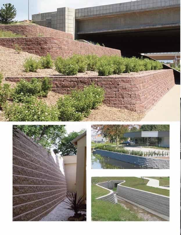
60 9
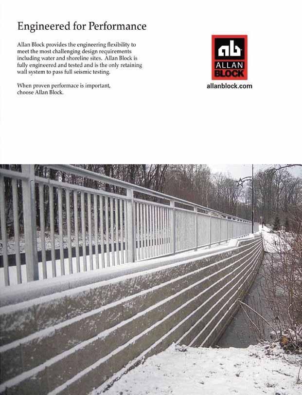
61 0
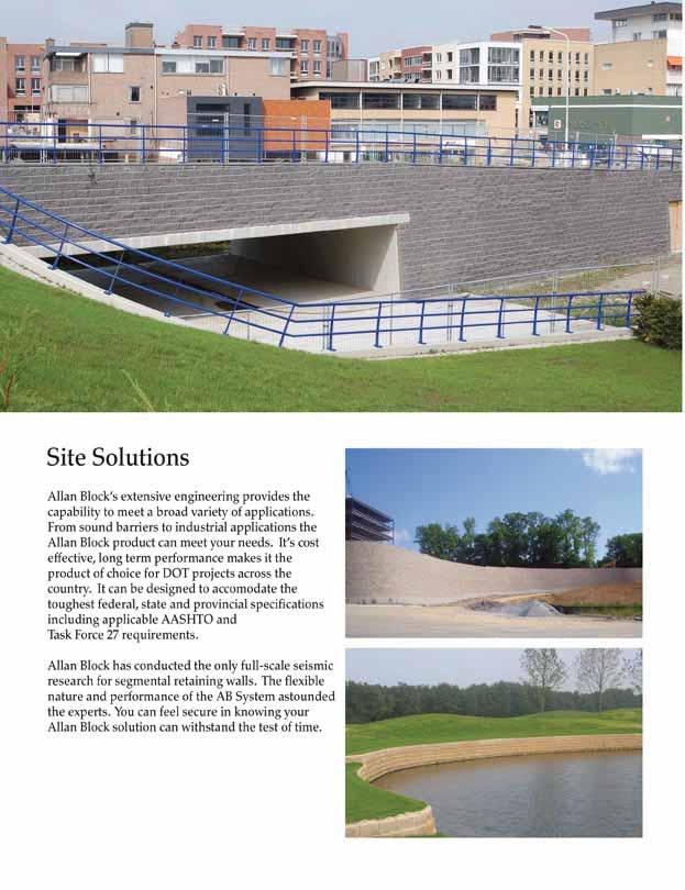
62 1
63 2


64 The information and product applications illustrated in this manual have been carefully compiled by the Allan Block Corporation and, to the best of our knowledge, accurately represent Allan Block product use. Final determination of the suitability of any information or material for the use contemplated and its manner of use is the sole responsibility of the user. Structural design analysis shall be performed by a qualified engineer Allan Block Corporation, 00 Industrial Blvd., #100, Edina, MN Phone 92809, Fax , US Pat. #,8,2, #,92,1, #,22,2 & #,8,2 Canadian Pat. #2,012,28 & #2,1, Australian Pat. #82,9 & #1,0 Europe Pat. #9,1 & #99,08,21.9 Germany Pat. #9,2,. Japan Pat. #,12,10 Mexico Pat. #189,8 Taiwan Pat. #NI229 Int l And Other Patents Pending DOC. #R010808
allanblock.com Commercial Installation Manual for Allan Block Retaining Walls allanblock.com
 Commercial Installation Manual for Allan Block Retaining Walls About Us Allan Block is a leading provider of patented retaining wall systems for largescale commercial, industrial, roadway and residential
Retaining Wall Systems
 Retaining Wall Systems A family of Retaining Wall Products The versatile Allan Block product line allows easy design and construction of retaining walls to meet specific engineering and site requirements.
AB Fieldstone Collection Installation Manual
 Allan Block Retaining Walls AB Fieldstone Collection Installation Manual Represented in India by PraYoSa - Offering World Class Products to Beautify Indian Landscapes PraYoSa Buildmat Pvt. Ltd. 2,Sachinam
Allan Block. Table of Contents. allanblock.com
 allanblock.com AB Fieldstone Collection Facing Series: Cascade Color: Rustic Creek Allan Block Allan Block is a leading provider of patented retaining wall systems. For over twenty years Allan Block has
Allan Block. Table of Contents. allanblock.com
 AB Fieldstone Collection Facing Series: Sierra Color: Sandstone allanblock.com Table of Contents Allan Block Allan Block is a leading provider of patented retaining wall systems. For over twenty five years
Specification Guidelines: Allan Block Modular Retaining Wall Systems
 Specification Guidelines: Allan Block Modular Retaining Wall Systems The following specifications provide Allan Block Corporation's typical requirements and recommendations. At the engineer of record's
NOVEMBER 2016 GRANDWALL. retaining walls installation guide
 NOVEMBER 2016 GRANDWALL retaining walls installation guide RETAINING WALL INSTALLATION GUIDE RETAINING WALL information Austral Masonry Grandwall retaining wall blocks are an ideal choice for retaining
SPECIFICATIONS FOR PRECAST MODULAR BLOCK RETAINING WALL SYSTEM (revised 5/8/7)
") Page 1 of 7 STONE STRONG SYSTEMS SPECIFICATIONS FOR PRECAST MODULAR BLOCK RETAINING WALL SYSTEM (revised 5/8/7) PART 1: GENERAL 1.01 Description A. Work includes furnishing and installing precast modular
Page 1 of 7 STONE STRONG SYSTEMS SPECIFICATIONS FOR PRECAST MODULAR BLOCK RETAINING WALL SYSTEM (revised 5/8/7) PART 1: GENERAL 1.01 Description A. Work includes furnishing and installing precast modular
Tasman Retaining Wall System
 Tasman Retaining Wall System The Tasman Retaining Wall System incorporates purpose made corners and capping units to provide classical reconstructed stone retaining walls for any landscape situation. From
ICC-ES Evaluation Report Issued July 1, 2011 This report is subject to renewal in one year.
 ICC-ES Evaluation Report ESR-1959 Issued July 1, 2011 This report is subject to renewal in one year. www.icc-es.org (800) 423-6587 (562) 699-0543 A Subsidiary of the International Code Council DIVISION:
AUGUST 2017 HASTINGS. retaining walls installation guide
 AUGUST 2017 HASTINGS retaining walls installation guide RETAINING WALL INSTALLATION GUIDE RETAINING WALL information Austral Masonry retaining wall blocks are an ideal choice for retaining walls in gardens,
SECTION SPECIFICATION FOR STONEBRIDGE RETAINING WALL SYSTEM
 SECTION 32 32 23 SPECIFICATION FOR STONEBRIDGE RETAINING WALL SYSTEM PART 1: GENERAL 1.01 Scope Work includes furnishing all materials, labor, equipment, and supervision to install a Stonebridge segmental
Anchorplex retaining wall construction guide. Building. Anchorplex. Retaining Wall Systems
 Anchorplex retaining wall construction guide Building Anchorplex Retaining Wall Systems Table of Contents and ow to Use This Guide table of contents ow to Use This Guide. 2 About the Anchorplex System.
Construction Procedures
 Construction Procedures 2014 Rev. 1.6 1 Introduction This manual presents the methods and procedures necessary for the proper erection of a LOCK+LOAD retaining wall. problems later during the service life
G R A V I T Y / G E O G R I D
 GRAVITY/GEOGRID MAGNUMSTONE Overview note: bolded terms are defined in our online glossary at www.cornerstonewallsolutions.com The MagnumStone retaining wall system was developed with the installer in
Best Practices for Allan Block Segmental Retaining Wall Design For Residential and Commercial Applications
 The intent of this document is to communicate the best practices for design of Segmental Retaining Walls (SRW) as determined by Allan Block Corporation based on 25 plus years of research, design and field
VERTI-BLOCK - DESIGN MANUAL
 Company Information General Information Verti-Block is the latest innovative forming system from Verti-Crete, LLC. Recognized worldwide for outstanding aesthetics and performance, Verti-Crete s proprietary
Redi Rock Specification and Installation Manual
 Redi Rock Specification and Installation Manual 1.0 General Scope This Specification covers the Design, Materials and Installation of Redi Rock modular block Retaining and Freestanding Wall systems as
NOVEMBER 2016 MAGNUMSTONE. retaining walls installation manual
 NOVEMBER 2016 MAGNUMSTONE retaining walls installation manual AUSTRAL MASONRY CONTENTS Magnumstone Installation Guide 04 Overview 07 Unit Specifications 08 Installation 08 Gravity MagnumStone Wall 16 Geogrid
CONCRETE SEGMENTAL RETAINING WALL SYSTEM
 CONCRETE SEGMENTAL RETAINING WALL SYSTEM PART 1: GENERAL SPECIFICATIONS 1.01 Work Included A. Work shall consist of furnishing and constructing a Rockwood Classic 8, Classic 6 and Legend unit segmental
How To Install Your Cambridge Pavingstones System How To Install Your Cambridge Segmental Retaining Wall System
 4 How To Install Your Cambridge Pavingstones System Step 1. Preparation: Sketch a diagram of area to be paved. Square off a 90-degree corner. Set stakes for outside perimeters 6 inches away from area.
INSPECTION GUIDE FOR SEGMENTAL RETAINING WALLS TEK 18-11B
 An information series from the national authority on concrete masonry technology INSPECTION GUIDE FOR SEGMENTAL RETAINING WALLS TEK 18-11B Quality Assurance and Testing (2012) INTRODUCTION Segmental retaining
HOW TO BUILD Garden Walls Frestanding & Landscape Walls
 HOW TO BUILD Garden Walls Frestanding & Landscape Walls 10 Cambridge Wall Book Garden walls This layout depicts a common application of landscape and freestanding designs together in one wall with Columns
MODULAR CONCRETE RETAINING WALL
 MODULAR CONCRETE RETAINING WALL PART 1: GENERAL 1.01 Description A. Work shall consist of furnishing and construction of a KEYSTONE Retaining Wall System or equal in accordance with these specifications
STANDARD SPECIFICATION FOR CRIBLOCK CONCRETE CRIBWALL
 STANDARD SPECIFICATION FOR CRIBLOCK CONCRETE CRIBWALL 1. SCOPE 2. DESIGN 3. MATERIALS 4. CONSTRUCTION 5. METHOD OF MEASUREMENT AND PAYMENT SCOPE This Specification sets out requirements for the design,
Design Manual: Gravity Wall. Section 1
 Design Manual: Gravity Wall Section 1 A Design Manual: Gravity Wall General Information Company Information Verti-Block is the latest innovative forming system from Verti-Crete, LLC. Recognized worldwide
15 lbs (6.8 kg) Approx. Weight. AB Junior. AB Jumbo. 35 lbs (16 kg) Approx. Weight
 Approx. Weight. AB Junior. AB Jumbo. 35 lbs (16 kg) Approx. Weight") 1 2 The Garden Wall Collection by Allan Block Choose the Right Block. Select the block with the right size and style for your gardening project. AB Garden Accent Textured on both sides, our lightest block
1 2 The Garden Wall Collection by Allan Block Choose the Right Block. Select the block with the right size and style for your gardening project. AB Garden Accent Textured on both sides, our lightest block
The Garden Wall Collection
 1 2 The Garden Wall Collection by Allan Block The Garden Wall Collection gives you three choices for building Great Gardens! 3 Choose the Right Block. Select the block with the right size and style for
Tasman Retaining Wall
 Tasman Retaining Wall EVALUATION AND INSTALLATION GUIDE Landscaping Tasman Retaining Wall Evaluation and Installation Guide This installation guide demonstrates the basics on how to construct: A. Tasman
Tasman and Norfolk Retaining Wall
 Tasman and Norfolk Retaining Wall Evaluation and Installation Guide BAINES We deliver Sydney s Best! Order online: bcsands.com.au Call: (02) 8543 3400 Taren Point & Mascot Tasman and Norfolk are registered
BELGARD.COM. Tandem Wall Segmental Retaining Wall System BELGARD.COM 1
 BELGARD.COM Tandem Wall Segmental Retaining Wall System BELGARD.COM 1 2 For more information visit Belgard.com Table of Contents Tandem Wall System...4 Features & Benefits...5 Installation Instructions...6
Design and Installation Guidelines for Retaining Walls. 1 P age. Geo Products, LLC 8615 Golden Spike Lane Houston, TX Phone:
 Design and Installation Guidelines for Retaining Walls 1 P age Geo Products, LLC 8615 Golden Spike Lane Houston, TX 77086 Phone: 281.820.5493 2011 Geo Products, Fax: 281.820.5499 LLC www.geoproducts.org
LANDSCAPE RETAINING WALLS
 SUDAS Standard Specifications Division 9 - Site Work and Landscaping Section 9070 - Landscape Retaining Walls LANDSCAPE RETAINING WALLS PART - GENERAL.0 SECTION INCLUDES A. Modular Block Retaining Walls
cambridgewallsupport.com cambridgepavers.com
 cambridgewallsupport.com cambridgepavers.com INDEX Inside This Guide Page Introduction to Sigma Wall Systems 3 Sigma Stones 4 Building a Wall 6 Foundation 7 Installation 9 Projects 19 Installing Sigma
DESIGN CONSIDERATIONS FOR NSWS NATURAL STONE RETAINING AND FREE-STANDING WALL SYSTEMS
 DESIGN CONSIDERATIONS FOR NSWS NATURAL STONE RETAINING AND FREE-STANDING WALL SYSTEMS Natural Stone Wall Solutions, Inc (NSWS ) 2352 Main Street, Suite 103 Concord, MA 01742 (978) 461-1777 Concept and
CAST STONE WALL TECHNICAL INSTALLATION GUIDE
 CAST STONE WALL TECHNICAL INSTALLATION GUIDE Single Sided Cast Stone Wall and Cast Stone Wall Face Shells Aspen Single Sided Cast Stone Wall and Cast Stone Wall Fire Pit Kit Breckenridge Double Sided Cast
MUTUAL MATERIALS TECH SHEET RomanStack. Coverage* 4.5 pcs / ft² (48.44 pcs / m²) 3,242 lb (1,470 kg) 4 x 8 Cap Unit. 1.6 pcs / ln ft (4.
 3,242 lb (1,470 kg) 4 x 8 Cap Unit. 1.6 pcs / ln ft (4.") Available in three wall block sizes and two cap sizes accompanied by 90 corner units. Combine multiple sizes of RomanStack to create intricate Ashlar, repeating or random patterns. Each size utilizes a
Available in three wall block sizes and two cap sizes accompanied by 90 corner units. Combine multiple sizes of RomanStack to create intricate Ashlar, repeating or random patterns. Each size utilizes a
GRANDE WALL large CONCRETE BLOCKS FOR THE CONSTRUCTION OF RETAINING WALLS. 1339_Feuillet_Permacon_Grande_ang.indd 1
 GRANDE WALL large CONCRETE BLOCKS FOR THE CONSTRUCTION OF RETAINING WALLS 1339_Feuillet_Permacon_Grande_ang.indd 1 27-05-15 14:03 GRANDE WALL The Grande wall system is designed for building retaining walls
Section (02830) MODULAR CONCRETE RETAINING WALL
 MODULAR CONCRETE RETAINING WALL") Section 323223 (02830) MODULAR CONCRETE RETAINING WALL PART 1: GENERAL 1.01 Description A. Work shall consist of furnishing and constructing a VERDURA Retaining Wall System (or approved equal) in accordance
Section 323223 (02830) MODULAR CONCRETE RETAINING WALL PART 1: GENERAL 1.01 Description A. Work shall consist of furnishing and constructing a VERDURA Retaining Wall System (or approved equal) in accordance
Section ( ) SPECIFICATION FOR SEGMENTAL CONCRETE UNIT RETAINING WALL
 SPECIFICATION FOR SEGMENTAL CONCRETE UNIT RETAINING WALL") Section 02834 (32 32 23) SPECIFICATION FOR SEGMENTAL CONCRETE UNIT RETAINING WALL PART 1: GENERAL 1.01 Description A. Work shall consist of furnishing and construction of a County Materials Retaining Wall
Section 02834 (32 32 23) SPECIFICATION FOR SEGMENTAL CONCRETE UNIT RETAINING WALL PART 1: GENERAL 1.01 Description A. Work shall consist of furnishing and construction of a County Materials Retaining Wall
DIVISION: EXTERIOR IMPROVEMENTS SECTION: RETAINING WALLS SECTION: SEGMENTAL RETAINING WALLS REPORT HOLDER:
 0 Most Widely Accepted and Trusted ICC ES Evaluation Report ICC ES 000 (800) 423 6587 (562) 699 0543 www.icc es.org ESR 3073 Reissued 07/2017 This report is subject to renewal 07/2018. DIVISION: 32 00
Uwall UNIVERSAL CONSTRUCTION MANUAL
 Uwall UNIVERSAL Retaining Wall System CONSTRUCTION MANUAL TM President s Letter CSI is a leader in its industry supplying precast infrastructure products throughout New England and beyond since 1972, developing
Ohio Department of Transportation Division of Production Management Office of Geotechnical Engineering. Geotechnical Bulletin
 Ohio Department of Transportation Division of Production Management Office of Geotechnical Engineering Geotechnical Bulletin GB 2 SPECIAL BENCHING AND SIDEHILL EMBANKMENT FILLS Geotechnical Bulletin GB2
ENGINEERING DIRECTIVE
 Number: E-95-001 Date: 2/2/95 ENGINEERING DIRECTIVE Ross B. Dindio (Signature on Original) CHIEF ENGINEER The purpose of this engineering directive is to formally notify ALL Department engineering personnel
SECTION PERMEABLE INTERLOCKING CONCRETE UNIT PAVEMENT
 SECTION 32 14 13 19 PERMEABLE INTERLOCKING CONCRETE UNIT PAVEMENT SECTION 32 14 13 19 PERMEABLE INTERLOCKING CONCRETE UNIT PAVEMENT PART 1 - GENERAL 1.1 SUMMARY A. Section Includes: 1. Permeable Articulating
SEGMENTAL BLOCK RETAINING WALLS. Comply with Division 1 - General Provisions and Covenants, as well as the following:
 SEGMENTAL BLOCK RETAINING WALLS PART 1 - GENERAL 1.01 SECTION INCLUDES Segmental Block Retaining Walls 1.02 DESCRIPTION OF WORK Constructing segmental block retaining walls. 1.03 SUBMITTALS Comply with
SECTION RIPRAP, BOULDERS, AND BEDDING
 SECTION 31 37 00 RIPRAP, BOULDERS, AND BEDDING PART 1 GENERAL 1.01 SECTION INCLUDES A. The WORK includes excavation, grading, and installation of riprap, boulders, soil riprap, void-filled riprap, and
Trusted ICC ES. Conformity! Evaluation. ICC-ES Evaluation
 0 Most Widely Accepted and Trusted ICC ES Evaluation Report ICC ES 000 (800) 423 6587 (562) 699 0543 www.icc es.orgg ESR 2113 Reissued 08/2017 This report is subject to renewal 08/2019. DIVISION: 32 00
Welcome. Technical Bulletin #1 Shoreline, Waterway and Retention Pond Protection. Technical Bulletin #2 VERSA-LOK Stairs
 Welcome Welcome to the VERSA-LOK Mosaic Retaining Wall System Design and Installation Guidelines. Welcome to the VERSA-LOK Mosaic Retaining Wall System Design and Installation Guidelines. This guide applies
at home installation guide Manufactured by:
 at home outdoorsproduct and installation guide Manufactured by: Product and Installation Guide Wall Systems Table of Contents Wall Systems...3-7 Project Planning and Installation... 8-11 DIY Retaining
decorative Stylish AND Retaining Wall - Wallstone Wallstone Charcoal
 Retaining Wall - Wallstone decorative AND Stylish Wallstone Charcoal Wallstone has many of the features of other systems but with the added advantage of choice between a vertical wall or a setback wall.
ITEM D-701 PIPE FOR STORM DRAINS AND CULVERTS
 ITEM D-701 PIPE FOR STORM DRAINS AND CULVERTS 701-1 DESCRIPTION 701-1.1 This item shall consist of the construction of pipe culverts, and storm drains, removal of existing storm pipes, connections to existing
Wall Modular Block Mechanically Stabilized Earth, Item S.
 Wall Modular Block Mechanically Stabilized Earth, Item 532.0300.S. A Description (1) This special provision describes designing, furnishing materials and erecting a permanent earth retention system in
CHARACTERISTICS CSA A TECHO-BLOC Compressive strength psi [45 MPa] min.
![CHARACTERISTICS CSA A TECHO-BLOC Compressive strength psi [45 MPa] min.](/thumbs/74/69637242.jpg "CHARACTERISTICS CSA A TECHO-BLOC Compressive strength psi [45 MPa] min.") PATIOS, WALKWAYS, POOLSIDES & STEPPING STONES PHYSICAL AND GEOMETRICAL CHARACTERISTICS CHARACTERISTICS CSA A231.1 2 TECHO-BLOC Compressive strength - 6 500 psi [45 MPa] min. Flexural strength 650 psi [4.5
PATIOS, WALKWAYS, POOLSIDES & STEPPING STONES PHYSICAL AND GEOMETRICAL CHARACTERISTICS CHARACTERISTICS CSA A231.1 2 TECHO-BLOC Compressive strength - 6 500 psi [45 MPa] min. Flexural strength 650 psi [4.5
DESIGNING AND CONSTRUCTION OF T-WALL RETAINING WALL SYSTEM
 Istanbul Bridge Conference August 11-13, 2014 Istanbul, Turkey DESIGNING AND CONSTRUCTION OF T-WALL RETAINING WALL SYSTEM T. C. NEEL and K.BOZKURT ABSTRACT This work shall consist of the design, manufacture
MSE WALLS CASE STUDIES. by John G. Delphia, P.E. TxDOT Bridge Division Geotechnical Branch
 MSE WALLS CASE STUDIES by John G. Delphia, P.E. TxDOT Bridge Division Geotechnical Branch COMMON RETAINING WALL TYPES CONCRETE BLOCK MSE TEMPORARY EARTH SPREAD FOOTING Gabions Drilled Shaft Soil Nail Tiedback
CITY OF LETHBRIDGE SECTION Construction Specifications SIDEWALK CONSTRUCTION PAGE 1 of 5
 Construction Specifications SIDEWALK CONSTRUCTION PAGE 1 of 5 1.0 EXCAVATION AND FILL 1.1 GENERAL.1 The excavation or fill shall be made to provide proper grade, lines and crosssection for the laying of
NOVEMBER 2016 MAGNUMSTONE. retaining walls technical manual
 NOVEMBER 2016 MAGNUMSTONE retaining walls technical manual AUSTRAL MASONRY MAGNUMSTONE Technical Manual THE SYSTEM AND UNITS 04 The System 05 The Units 06 Standard Unit 07 Standard Base Unit 08 Standard
Tasman. Retaining Wall System. Available From. Choose the original Tasman block. Beware of imitations!
 Available From Tasman Retaining Wall System Choose the original Tasman block. Beware of imitations! Prestige & Quality Near Vertical Walls Do It Yourself No Concrete Footings Flexible 90 Corners, Steps,
NORTHERN QLD LANDSCAPING COLLECTION RETAINING WALLS. style and function
 NORTHERN QLD LANDSCAPING COLLECTION 2017-18 RETAINING WALLS style and function RETAINING WALLS / NTH QLD / 2 / style and function BEAUTIFUL PRODUCTS with enduring style Our range of coloured, standard
Description. This work shall consist of furnishing materials and placement of modular block wall constructed in accordance with
 MODULAR CONCRETE BLOCK RETAINING WALL WITH GROUND REINFORCING The Standard Specifications are revised as follows: 732-R-310r 1of 11 Rev. 12-03-03 SECTION 105, AFTER LINE 48, INSERT AS FOLLOWS: When constructing
Steps And Stairs Installation Steps In Wall - Option 1 Steps In Front of Walls - Option 2 Steps In Wall; 10 (25cm) Tread - Option 3 Step Parallel to
 Tread - Option 3 Step Parallel to") Steps And Stairs Installation Steps In Wall - Option 1 Steps In Front of Walls - Option 2 Steps In Wall; 10 (25cm) Tread - Option 3 Step Parallel to Wall - Option 4 Steps and Stairs Q & A E CONSTRUCTION
Steps And Stairs Installation Steps In Wall - Option 1 Steps In Front of Walls - Option 2 Steps In Wall; 10 (25cm) Tread - Option 3 Step Parallel to Wall - Option 4 Steps and Stairs Q & A E CONSTRUCTION
Installation guide WALLS
 Installation outline 6" (150 mm) min. 6" (150 mm) min. 12" (300 mm) min. 6" (150 mm) min. 01 EXCAVATION A. Check the location of existing structures and utilities before starting the excavation. B. Dig
PERMEABLE INTERLOCKING PAVERS
 PERMEABLE INTERLOCKING PAVERS PART 1 - GENERAL 1.01 SECTION INCLUDES A. Subgrade Preparation B. Placement of Storage Aggregate C. Placement of Filter Aggregate D. Placement of Bedding Course E. Placement
Steps And Stairs Installation Option 1 - Steps In Wall Option 2 - Steps With Plant Space Option 3 - Steps In Front of Walls Option 4 - Steps Along
 Steps And Stairs Installation Option 1 - Steps In Wall Option 2 - Steps With Plant Space Option 3 - Steps In Front of Walls Option 4 - Steps Along Wall Face Option 5 - Steps In Wall; 10 (25cm) Tread Option
BIO-AQUIFER STORM SYSTEM
 BIO-AQUIFER STORM SYSTEM Specifications for Construction PART 1 GENERAL 1.01 SECTION INCLUDES A. Providing labor, materials, tools and equipment to furnish and install a permeable concrete paving stone
SPECIAL PROVISIONS - SP2014 BOOK Page 1 October 8, 2013
 SPECIAL PROVISIONS - SP2014 BOOK Page 1 S-1 (2104) REMOVE AND REPLACE BITUMINOUS PAVEMENT (ADA) Always include SP2014-119 (PLANT MIXED ASPHALT PAVEMENT) or SP2014-121 (PLANT MIXED ASPHALT PAVEMENT FOR
Section 401. PIPE CULVERTS
 401.02 Section 401. PIPE CULVERTS 401.01. Description. This work consists of constructing pipe culverts of the size and class required, including excavation and backfill. 401.02. Materials. Provide materials
MACHINE-LAY Installation Manual
 MACHINE-LAY Installation Manual PaveDrain Installation Manual Table of Contents Section 1: Base Preparation (pages 3 6) Section 2: Machine-Lay PaveDrain Blocks (pages 8 11) Section 3: Edge Restraints (pages
LS 2519 CONCRETE PAVER PAVEMENT RECONSTRUCTION
 LS 2519 CONCRETE PAVER PAVEMENT RECONSTRUCTION A. Section Includes B. References C. Quality Assurance D. Submittals E. Delivery, Storage and Handling F. Environmental Conditions G. Summary H. Concrete
ITEM 6 CONCRETE CURBS, GUTTERS, AND SIDEWALKS
 ITEM 6 CONCRETE CURBS, GUTTERS, AND SIDEWALKS 6.1 DESCRIPTION This work shall consist of constructing curbs, gutters, sidewalks, ramps, local depressions and driveways of the form and dimensions shown
Installation guide WALLS
 WALLS Installation outline 6" (150 mm) min. 6" (150 mm) min. 12" (300 mm) min. 6" (150 mm) min. 01 EXCAVATION A. Check the location of existing structures and utilities before starting the excavation.
SPECIFICATION FOR REINFORCED SOIL WALL
 SPECIFICATION FOR REINFORCED SOIL WALL 1.0 EXTENT OF WORK The work shall consist of Reinforced Soil walls built in accordance with this specification and in conformity with the lines, levels and details
Geoguide 6 The New Guide to Reinforced Fill Structure and Slope Design in Hong Kong
 Geoguide 6 The New Guide to Reinforced Fill Structure and Slope Design in Hong Kong Geotechnical Engineering Office Civil Engineering Department The Government of the Hong Kong Special Administrative Region
Diversion Dikes. Fe=0.95
 2.2 Diversion Dike Erosion Control Description: A diversion dike is a compacted soil mound, which redirects runoff to a desired location. The dike is typically stabilized with natural grass for low velocities
10 EXTREME BASEMENT PANELS
 10 EXTREME BASEMENT PANELS On Granular Footings 1. The type of soil is a factor in determining foundation construction details such as footing design, backfill, and drainage provisions. Soils are classified
SECTION 19 - TRENCH EXCAVATION, BEDDING AND BACKFILL TABLE OF CONTENTS
 SECTION 19 - TRENCH EXCAVATION, BEDDING AND BACKFILL TABLE OF CONTENTS Section Page 19-1 TRENCH EXCAVATION... 19.1 19-1.01 Exploratory Excavation... 19.1 19-1.02 Trench Width... 19.1 19-1.02.A Storm Drain
A.2.a Random Riprap... Table
 3601 RIPRAP MATERIAL 3601.1 SCOPE Provide stone and filter layer material for use in random or hand-placed riprap, gabion, and revet mattress construction. 3601.2 REQUIREMENTS A Stones A.1 Quality Provide
4 EXTREME FOUNDATION PANELS
 4 EXTREME FOUNDATION PANELS For House Crawl Space On Concrete Footings 1. The type of soil is a factor in determining foundation construction details such as footing design, backfill, and drainage provisions.
Contact Clark Public Utilities Construction Services department at (360) to initiate a request for service.
 to initiate a request for service.") CHAPTER3 Clark Public Utilities Commercial Electric Service Handbook Commercial Underground Services Preparing for the installation The following checklist will assist in preparing a project for the installation
CHAPTER3 Clark Public Utilities Commercial Electric Service Handbook Commercial Underground Services Preparing for the installation The following checklist will assist in preparing a project for the installation
Soils Information Retained soils, foundation soils, reinforced soils, etc. Project Specification Design and project information and requirements.
 Retaining Walls ReCon retaining walls are classified as Precast Modular Block Walls or PMBWs. When designing a PMBW, it is critical that all of the appropriate information be gathered so that a proper
C. Foundation stabilization for pipe and utility structures.
 PART 1 - GENERAL 1.1 SECTION INCLUDES A. Excavating, backfilling, and compacting for utilities, including pipe, structures, and appurtenances. B. Control of water in trenches. C. Foundation stabilization
2011 INSTALLATION MANUAL
 Redi-Rock International 2 PRE-CONSTRUCTION CHECKLIST... Before you start construction of a Redi-Rock wall, take the time to complete necessary planning and preparation. This process will help ensure a
StormTech Construction Guide
 A division of StormTech solid end caps and pre-cored end caps StormTech chambers StormTech manifolds and fittings Acceptable fill materials per Table 1 Woven and non-woven geotextiles 80-7 DC REQUIRED
Concrete DESIGNS QUARTER 1: 2005 ASLA CPE
 Concrete QUARTER 1: 2005 DESIGNS ASLA CPE Ret 3/05 4 taining Value By Deborah Rider Allen ASLA CPE AIA/ASLA Learning Objective After reading this article you should understand: The requirements of designing
INDEX FOR SPECIFICATIONS FOR REMOVING CULVERTS AND PLACING CULVERTS SCOPE... 1
 March 2002 No. 400 INDEX FOR SPECIFICATIONS FOR REMOVING CULVERTS AND PLACING CULVERTS 400. 1 SCOPE... 1 400. 2 REMOVING CULVERTS AND TIMBER STRUCTURES 2.1 Concrete and Metal Pipe Culverts... 1 2.2 Structural
1.0 Introduction. 2.0 Retaining Wall Principles. 3.0 Retaining Wall Installation. 4.0 Installation Details. 5.0 Installation Tables
 1.0 Introduction 1.1 Welcome 01 1.2 System Components 02 1.3 Tools & Equipment 03 1.4 Starting Your Project 04 1.5 Technical Support 05 2.0 Retaining Wall Principles 2.1 Wall Types 06 3.0 Retaining Wall
BITUMEN-SET PRECAST CONCRETE PAVING SLABS
 SECTION 32 14 13.16 BITUMEN-SET PRECAST CONCRETE PAVING SLABS (1995 MasterFormat Section 02784) NOTE: This guide specification is the U.S. for concrete paving slabs adhered with a neoprene mastic to a
SECTION 1100 GRADING 1102 MATERIALS AND DEFINITIONS.
 SECTION 1100 GRADING 1101 SCOPE. This section covers the performance of all work required for grading the project in coordination with all previous work performed at the locations shown on the contract
Products for the residential Market. Where. dreams. & yards meet. anchorwall.com
 Products for the residential Market Where dreams & yards meet Easy installation is more than lip service. No pins. No mortar. No misalignments. Rear-lip locator, invented by Anchor, makes installation
In preparation for constructing buildings on a property, the builder. Site Preparation CHAPTER
 CHAPTER 3 Site Preparation In preparation for constructing buildings on a property, the builder must consider a number of factors related to code requirements. The buildings must be located according to
MOA Project # Golden View Drive Intersection & Safety Upgrades
 Appropriate transitions can include extending the insulation beyond the roadway improvements, reducing the insulation thickness, or angling the insulation downward. Use of a frost tolerant section, an
INDEX FOR SPECIFICATIONS FOR JACKING CULVERTS THROUGH EMBANKMENTS SCOPE... 2
 INDEX FOR SPECIFICATIONS FOR JACKING CULVERTS THROUGH EMBANKMENTS 410. 1 SCOPE... 2 410. 2 DEFINITIONS 2.1 Tunneling and Jacking... 2 2.2 Tunneling... 2 2.3 Jacking... 2 410. 3 MATERIALS 3.1 General...
SECTION A1 EXCAVATION AND BACKFILL GENERAL
 SECTION A1 EXCAVATION AND BACKFILL GENERAL The work under this section shall include all excavation to such width and depth as shown on the drawings, specified herein, or ordered by the Engineer. Such
PAVING SLABS ON A CONCRETE BASE
 SECTION 32 14 13.16 PAVING SLABS ON A CONCRETE BASE (1995 MasterFormat Section 02784) Note: This guide specification for the U.S. is for paving slabs on a sand bed over concrete for pedestrian applications.
Installation Manual. ArchCast Bridge. 3-Sided Precast Concrete Bridge Structure
 ArchCast Bridge 3-Sided Precast Concrete Bridge Structure Installation Manual Salem Location: 749 West Commercial Ave. Salem, IL 62881 (618) 548-1190 countymaterials.com Email: info@countymaterials.com
SECTION INTERLOCKING CONCRETE PAVERS
 SECTION 23 14 13 INTERLOCKING CONCRETE PAVERS (1995 MasterFormat Section 02780) Note: This guide specification for concrete paver applications in the U.S. for concrete pavers and bedding sand over a compacted
SEGMENTAL RETAINING WALL SYSTEMS
 SEGMENTAL RETAINING WALL SYSTEMS TECHNICAL SPECIFICATIONS Adbri Masonry Adbri Masonry is Australia s leading masonry manufacturer supplying quality concrete bricks, blocks, pavers, retaining walls, erosion
SECTION INTERLOCKING PRECAST CONCRETE UNIT PAVERS
 SECTION 321413.13 INTERLOCKING PRECAST CONCRETE UNIT PAVERS PART 1 - GENERAL 1.1 SUMMARY A. This Section includes the following: 1. Interlocking concrete paver units. 2. Sand setting bed. 3. Sand joint
GROUNDtrax GROUNDGRIDZ
 INSTALLATION GUIDE The product is asymmetric and must be lifted by placing the hands on the diagonally opposed corners of the central paver (as shown). 1. Place grids onto the prepared well consolidated