SECURE. UNIVERSAL. MOUNTING. Tilt Kit Installation Manual
|
|
|
- Sylvia Page
- 6 years ago
- Views:
Transcription


1 SECURE. UNIVERSAL. MOUNTING Tilt Kit Installation Manual
2 1.0 INTRODUCTION KITS / PRODUCT RANGE Leg Kits Rail Kits PREPARATION FOR INSTALLATION Applications Tools for Installation Additional Materials for Installation PLANNING THE INSTALLATION Site Locations Building / Installation Height Solar Panel Layout General Installation Notes INSTALLATION Leg Kit Installation Leg Kit Fixed Leg Kit Adjustable Mounting Rail Installation Solar Panel Module Installation Mid Clamps End Clamps Cable Management Features Integrated Cable Track Clip-in Cable Loop Ties SYSTEM COMPONENTS STANDARDS CONTACT DETAILS Page 2 of 19
3 1.0 INTRODUCTION Thank you for choosing LOCKSOLAR for your solar panel installation. The LOCKSOLAR, Tilt Kit has been designed specifically for Australian conditions and uses the highest quality materials in construction. The Tilt Kit system provides you with unequalled security for your valuable solar investment. The Tilt Kit is compliant with the structural design requirements of Australian / New Zealand standard AS 1170 and comes with a 10 year warranty. WARNING INSTALLATION OF THE TILT KIT SYSTEM IS INTENDED TO BE PERFORMED BY PROFESSIONALLY TRAINED INSTALLERS ONLY. ANY ATTEMPT TO INSTALL THE TILT KIT SYSTEM BY AN UNQUALIFIED INDIVIDUAL COULD RESULT IN INJURY OR DEATH The installer is solely responsible for: Complying with all applicable local and national building codes; Ensuring that the Tilt Kit and other products used in the installation are appropriate for the particular installation and the installation environment; Ensuring that the roof structure, its rafters, connections and other structural support members can withstand the installation of the Tilt Kit and solar panel modules under live building load conditions; Ensuring only Tilt Kit parts are used in the installation. Substitution of parts could lead to a failure in the Tilt Kit system; Ensuring that the roof attachments of the roof mounting brackets have sufficient pullout and shear capacities as installed; Maintaining the watertight integrity of the roof; Ensuring safe installation of all components of the system; Verifying that other loading factors including water, ice, snow and seismic loads do not affect the installation. Page 3 of 19
4 2.0 KITS / PRODUCT RANGE The Tilt Kit is a modular system and comes packaged in individual Leg Kits and Rail Kits so that each job can be customized cost effectively. Leg Kits include all you need for one leg installation. The number of Leg Kits required will depend on the amount of panels being installed. Rail Kits include all you need to secure your panels to the legs. All you need to successfully install your system in Australian city and suburban regions are included. 2.1 Leg Kits The Leg Kit system is available in modular kits to suit different angular needs. There are two adjustable leg kits to cater for angles between degrees and degrees. Two fixed angle kits at 30 degrees and 60 degrees are also available. Each Leg Kit comes with one long leg, one short leg and mounting components required. The number of leg kits required for installation will depend on the amount of panels being installed. Product Code Description Leg Angle RIB-TILT Tilt Kit Leg, degrees adjustable degrees RIB-TILT-30 Tilt Kit Leg, 30 degrees fixed 30 degrees RIB-TILT Tilt Kit Leg, degrees adjustable degrees RIB-TILT-60 Tilt Kit Leg, 60 degrees fixed 60 degrees 2.2 Rail Kits The Rail Kit system is available in modular kits to suit both 3 and 4 panel per rail installations. Each kit comes with 2 rails and enough mounting components to suit most applications. Product Code Description Rail Length (mm) RIB-2560 Tilt Kit Rail, 2560mm 2560 RIB-3410 Tilt Kit Rail, 3410mm 3140 Page 4 of 19


5 3.0 PREPARATION FOR INSTALLATION 3.1 Applications The Tilt Kit is designed for installation on residential and commercial buildings. The Tilt Kit is designed for mounting solar panel modules to flat steel roofs. 3.2 Tools for Installation You will need the following tools for installing the Tilt Kit system. 1. Cordless drill 2. Protective gloves and clothing 3. Security driver 4. Various wood screw drivers, including Phillips head driver and Torx head drivers 3.3 Additional Materials for Installation Our Tilt Kit system comes with just about everything you need to install the solar module panels. In order to ensure the watertight integrity of the roof you will need waterproofing materials. Other tools and materials may be required to prepare the roof structure for installation. Page 5 of 19


6 4.0 PLANNING THE INSTALLATION The Tilt Kit has been configured to meet a large percentage of common installation sites around Australia. Additional components are available to extend the performance of the system to suit unusual sites and installations. These consist of additional Leg Kits that are used to hold the installation to the roof structure. Please consult your Tilt Kit distributor for assistance in these situations. 4.1 Site Locations Australia is divided into several regions based on the maximum wind speed expected during peak storm activity identified in AS/NZ :2002. The Tilt Kit has been designed to be structurally sufficient in most areas in Australia where installations are located in Regions A, B, W and C. This includes all major city and suburban regions of Sydney, Melbourne, Brisbane, Adelaide, Canberra, Hobart and Perth. See figure 1 for wind areas. Figure 1 - Wind Regions - Australia AS/NZ1170.2:2.002 Some wind regions may require additional leg kits to be used in the installation. Please contact your Tilt Kit distributor for more information. Page 6 of 19

7 The terrain surrounding the installation has a major impact on the wind loadings that the installation must withstand. The Tilt Kit system has been found to be structurally sufficient for Terrain Category 2, 3 and 4. The Tilt Kit system can be used in rural locations but in some cases may require you to purchase additional Leg Kits to be used in the installation. Please contact your Tilt Kit distributor for more information. The Shielding and Topography Multipliers take into account protection by upwind local buildings and the increased exposure by gradient upwind of the site. The Tilt Leg system has been found to be structurally sufficient for Shielding and Topography multipliers of Building / Installation Height The Tilt Kit has been designed specifically for mounting on enclosed building to a height of 20 meters maximum above ground. If you are intending to use the Tilt Kit for installations higher than 20 m above ground level, then you may need to purchase additional Tilt Kit Leg Kits to be used in the installation. Please contact your Tilt Kit distributor for more information. 4.3 Solar Panel Layout The Tilt Kit is a modular system to which a range of solar panel modules can be mounted. The Rail Kit clamps the solar panel modules to parallel rails that are aligned with and tied structurally to the existing roof structure. With the use of the Leg Kits The Tile Kit needs to be sited within the perimeter of the roof and no closer to the roof edges than as follows; Figure 2 Installation Perimeter Zones Distance A (edge of panel to roof perimeter) must be a minimum of 20% of X and 20% of installation height Distance B (edge of panel to roof perimeter) must be a minimum of 20% of Y and 20% of installation height Layouts that will locate the solar panel modules closer to the roof edges will require engineering verification. Please consult your Tilt Kit distributor for further information. Page 7 of 19
8 4.4 General Installation Notes 1. Mounting rails should align with the spacing of the battens / purlins of the roof 2. The spacing between the mounting rails shall not be less than 50% of the length of the solar panel modules. 3. The mounting brackets should align with the rafters of the roof structure. 4. The mounting brackets shall be spaced evenly along the length of the mounting rail 5. The outer / end most mounting brackets shall be located evenly from the rail ends. Page 8 of 19

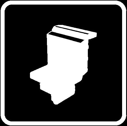
9 5.0 INSTALLATION Referring to the layout of the solar panel modules and Tilt Kit system, identify the positions of the mounting rails and locate the roof structure for attachment. 5.1 Leg Kit Installation The Leg Kit system provides the Tilt Legs pre-assembled in order to save on installation time. The mounting legs are attached to the roof structure through the roof sheeting. The placement and configuration of the different sized legs will determine the angle and direction of the panel Leg Kit Fixed The Tilt Kit - Leg Kit Fixed allows the panel to be placed at fixed angles of 30 or 60 degrees depending on which kit is purchased. Assembly steps: 1. Mark the installation points and ensure that installation points are located over the centre of the rafters. 2. Drill pilot holes in the steel roofing for the roofing screws. 3. Use the rubber pad supplied in the Leg Kit under each bracket and over the pilot holes to ensure a watertight connection 4. Align the bracket along the line of the roof structure and mounting rail. 5. Secure the bracket with the roofing screws. Page 9 of 19

10 5.1.2 Leg Kit Adjustable The Tilt Kit - Leg Kit Adjustable allows the panel to be placed at angles between degrees and degrees depending on which kit is purchased. The long leg is supplied secured in the minimum length configuration. It is recommended to adjust the panel angle after the solar panel modules have been securely installed. Assembly steps: 1. Mark the installation points and ensure that installation points are located over the centre of the rafters. 2. Drill pilot holes in the roofing for the roofing screws. 3. Use the rubber pad supplied in the Leg Kit under each bracket and over the pilot holes to ensure a watertight connection 4. Align the bracket along the line of the roof structure and mounting rail. 5. Secure the bracket with the roofing screws. WARNING ADJUSTABLE LEG DEGREE SHOULD NOT BE EXTENDED FURTHER THAN 627mm. ADJUSTABLE LEG DEGREE SHOULD NOT BE EXTENDED FURTHER THAN 1100mm Page 10 of 19


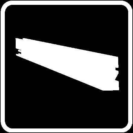
11 5.2 Mounting Rail Installation The Rail Kit system easily attaches to the Leg Kit s short and long legs. - Long Leg - Short Leg Assembly steps: 1. Attach the mounting rail to the short legs or long legs as shown. 2. The leg kit comes preassembled with rail fasteners. Insert the rail nut into the rail space as shown. 3. Position the mounting rail at the desired position aligning the ends of the rail and tighten the rail to the brackets Apply a torque of 8Nm to the bolt. Page 11 of 19

12 5.3 Solar Panel Module Installation WARNING ENSURE YOU FOLLOW ANY OF THE RECOMMENDATIONS AND INSTRUCTIONS OF THE SOLAR PANEL MODULE SUPPLIER IN HANDLING AND INSTALLING THE SOLAR PANEL MODULES. FOLLOW THE NEXT INSTRUCTIONS CAREFULLY. WHEN INSTALLING THE PANELS CORRECTLY USING THE TILT KIT SYSTEM THE SOLAR PANEL MODULES WILL NOT BE DAMAGED. The Solar panels are assembled to the Tilt Kit mounting rails 1 panel at a time starting from the center panel. Use a suitable means to prevent the panels slipping from the frame during installation. Once installed, the mounting clamps will hold the solar module panels in place. Until the clamps are securely installed, the solar panel module needs to be appropriately secured. Assembly steps: 1. Start by attaching a mid clamp to each mounting rail. 2. Using the following assembly steps for mid clamps and end clamps work from the center solar panel module to the end solar panel modules. Page 12 of 19


13 5.4 Mid Clamps Assembly steps - For solar panel module thickness of 35 mm to 45mm: 1. The mid clamps are preassembled with the fasteners for your convenience. 2. Attach the mid clamp to the mounting rail. 3. Position the mid clamp firmly against the edge of the solar panel module. 4. Turn the bolt to achieve a loose fit. 5. Slide the adjoining solar panel module along the rail and under the mid clamp. 6. Ensure that the mid clamp is tight against the solar panel modules. 7. Tighten the bolt. Torque bolt to 8 Nm. Assembly steps - For solar panel module thickness of 45 mm to 55 mm: 1. Disassemble the fasteners from the mid clamp assembly and remove the aluminium spacer tube from around the bolt. 2. Reassemble the fasteners to the mid clamp. 3. Attach the mid clamp to the mounting rail. 4. Position the mid clamp firmly against the edge of the solar panel module. 5. Turn the bolt to achieve a loose fit. 6. Slide the adjoining solar panel module along the rail and under the mid clamp. 7. Ensure that the mid clamp is tight against the solar panel modules. 8. Tighten the bolt. Torque bolt to 8 Nm. Page 13 of 19


14 5.5 End Clamps Assembly steps: 1. Determine the thickness of your solar panel module. 2. Start with the assembly of 1 set of end clamps on each of the mounting rails. The end clamps are designed to suit a variety of solar panel module thicknesses from 35mm to 55mm. Set the end clamp to suit the solar module panel. WARNING ENSURE THAT THE END CLAMP ONLY CONTACTS ONE POINT OF THE MOUNTING RAIL AND THE FRAME EDGE OF THE SOLAR PANEL MODULE. ADJUST THE END CLAMP HEIGHT TO ENSURE THAT THERE IS ONLY ONE POINT OF CONTACT WITH THE MOUNTING RAIL. 3. The end clamps come preassembled with the fasteners for your convenience. 4. Attach the end clamp to the mounting rail. 5. Tighten the end clamp firmly against the solar panel module. Torque bolt to 8 Nm. Page 14 of 19

15 5.6 Cable Management Features The Tilt Kit system incorporates a number of cable management features; Integrated Cable Track Assembly steps: 1. Push loose cable into integrated cable slot Note: Integrated cable slot will accommodate 2 to 3 cables. Page 15 of 19

16 5.6.2 Clip-in Cable Loop Ties Assembly steps: 1. Position Cable Loop Tie so that it runs parallel to rail and insert boss into rail clipping groove. 2. Maintaining some pressure, rotate clip clockwise to vertical, locked position. 3. Collect excess cable into loops and bend cable tie tail up to hold in place. 4. Push cable tie tail thru ratchet head and pull to tighten. Page 16 of 19


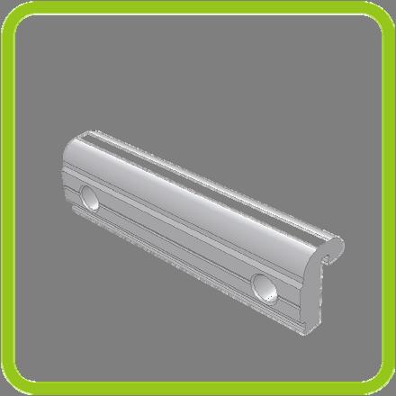
17 6.0 SYSTEM COMPONENTS Leg Kit Components: Short Leg Long Leg - Fixed Long Leg - Adjustable Roofing Screw Rubber Pad Page 17 of 19


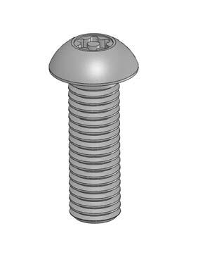
18 Rail Kit Components: Rail End Clamp Mid Clamp Joiner Cable Loop Tie Security Head Screw Page 18 of 19
19 7.0 STANDARDS Australian/New Zealand Wind Loading Standard AS/NZ S CONTACT DETAILS T: F: INT: E: Page 19 of 19
Clenergy ezrack SolarRoof Code-Compliant Planning and Installation With Australia AS/NZS1170
 Clenergy ezrack SolarRoof Code-Compliant Planning and Installation With Australia AS/NZS1170 The ezrack has been developed as a universal system for roof-mounting on pitched roofs. The use of patented
Conergy SolarFamulus II
 Conergy SolarFamulus II Installation manual www.conergy.com Table of Contents Table of Contents SolarFamulus II for universal use on flat roofs 1 Introduction 1 1.1 Short description 1 1.2 Intended use
Installation Guide EcoFoot5D High Density 5-Degree Ballasted Racking System Document No. ES10560
 Installation Guide Installation Guide EcoFoot5D High Density 5-Degree Ballasted Racking System Document No. ES10560 Rev 1.0, September 2017 Sales: 740-249-1877 Sales@EcolibriumSolar.com Field Support:
On-roof system Tau Installation manual
 On-roof system Tau Installation manual 810-0052 Table of Contents 1 Introduction 1 1.1 Short description 1 1.2 Intended use 1 1.3 Standards and guidelines 1 1.4 About these instructions 1 Tau The innovative
Mounting instructions
 Mounting instructions novotegra for tile roofs top-fix I TABLE OF CONTENTS 1 Notes... 1 2 Maintenance of the mounting system... 3 3 novotegra for tile roofs... 3 4 System components, tools and equipment...
PV Mounting System 2703 SERIES 200 UL GROUND MOUNT SYSTEM. SnapNrack Residential PV Mounting Systems Code Compliant Installation Manual
 PV Mounting System 2703 SERIES 200 UL GROUND MOUNT SYSTEM SnapNrack Residential PV Mounting Systems Code Compliant Installation Manual Series 200 UL Introduction Series 200 UL Introduction SnapNrack Series
ASSEMBLY INSTRUCTIONS RESIDENTIAL SOLUTION CROSSRAIL GROUND MOUNT SYSTEM USA
 ASSEMBLY INSTRUCTIONS RESIDENTIAL SOLUTION CROSSRAIL GROUND MOUNT SYSTEM USA TABLE OF CONTENTS TABLE OF CONTENTS SAFETY REGULATIONS MATERIALS REQUIRED ASSEMBLY ENGINEERING DRAWINGS TERMS AND CONDITIONS
MOUNTING SYSTEM FOR PITCHED ROOF WITH TILES. mounting system for pitched roof with tiles for solar panels in landscape setup. Rev
 MANUAL EN MOUNTING SYSTEM FOR PITCHED ROOF WITH TILES mounting system for pitched roof with tiles for solar panels in landscape setup ESDEC BV 2016 TABLE OF CONTENT 1. Introduction 1 2. General installation
INSTALLATION GUIDE Sika SolarMount 1 Exposition East West
 Exposition East West CONTENTS 1 Notes on the Sika SolarMount 1 system (Exposition East West) for PV solar arrays 3 2 Setting up on site 3 3 Required Tools for mounting Sika SolarMount 1 to Sika roofing
Mounting instructions. novotegra for trapezoidal metal - roof parallel
 Mounting instructions novotegra for trapezoidal metal - roof parallel I TABLE OF CONTENTS 1 Notes... 1 2 Maintenance of the mounting system... 3 3 novotegra for trapezoidal metal - roof parallel... 3 4
TRAPEZOIDAL SHEET METAL RAIL
 Photovoltaic Mounting Systems Assembly Instructions TRAPEZOIDAL SHEET METAL RAIL Mounting system for roofing with trapezoidal sheet metal S:FLEX GmbH 09/2017 / design and engineering is subject to change
INSTALLATION INSTRUCTIONS ENGLISH
 INSTALLATION INSTRUCTIONS ENGLISH Safety instructions 04 General notes 07 Material & tool requirements 08 System overview 10 installation of ALUTEC 12 Maintenance 27 04 INTENDED USE Creotecc mounting
GroundTrac. Installation Manual
 APPLICATION: The GroundTrac system is designed with a minimum amount of installed footings at greatly reduced labor. The system integrates with ordinary 1-1/2 schedule #40 galvanized water pipe. This ground
ST-AK 1/12. Photovoltaic Mounting Systems. Assembly Instructions. Mounting system for roofing with trapezoidal sheet metal
 Photovoltaic Mounting Systems Assembly Instructions ST-AK 1/12 Mounting system for roofing with trapezoidal sheet metal S:FLEX GmbH 09/2017 / design and engineering is subject to change 1 Index 1 Introduction
For Silverback Solar
 Washer, Electrical Equipment Bond WEEB Patent Pending INSTALLATION INSTRUCTIONS For Silverback Solar Please read carefully before installing. Wiley Electronics recommends that the sufficient details of
INSTALLATION INSTRUCTIONS ENGLISH
 INSTALLATION INSTRUCTIONS ENGLISH Safety instructions 04 General notes 07 Material & tool requirements 08 System overview 10 installation of CREODUR 11 Maintenance 22 04 INTENDED USE Creotecc mounting
Panel Jack Pro System BRACING, ALIGNMENT AND SCAFFOLDING EQUIPMENT
 IMPORTANT SAFETY INFORMATION FOR USERS OF THE REECHCRAFT, BRACING SYSTEM PLEASE READ BEFORE USE Panel Jack Pro System BRACING, ALIGNMENT AND SCAFFOLDING EQUIPMENT UK Edition 1.3 26/11/2012 1 TABLE OF CONTENTS
ValkPro+ Installation manual. Van der Valk Solar Systems. Use in combination with the Project Report of the ValkPVplanner. Solar Mounting Systems
 ValkPro+ Installation manual Use in combination with the Project Report of the ValkPVplanner Version 14 EN Van der Valk Solar Systems Solar Mounting Systems Please Note Table of contents This manual is
Mounting System MCG 1.1 Membrane-Connected Glass. System description
 Mounting System MCG 1.1 Membrane-Connected Glass System description SUNOVA MCG 1.1 System Fields of application: Not suitable for: (please inquire for other SUNOVA systems) The SUNOVA MCG system is a lightweight
PITCHED ROOF. Photovoltaic Mounting Systems. Assembly Instructions. for roofing tiles, plain tiles and slate
 Photovoltaic Mounting Systems Assembly Instructions PITCHED ROOF for roofing tiles, plain tiles and slate S:FLEX GmbH 09/2017 / design and engineering is subject to change 1 Index 1 Introduction 1.1 Intended
Smarter. Safer. Leaner.
 Smarter. Safer. Leaner. Fast Installation and Removal Decrease Leading Edge Exposure by 87% OSHA Compliant Versatile and Reusable Use Perimeter Protection Posts During Construction: At Building Perimeter
Axiom. SURFACE MOUNTED ARRAY Patient Headwall. Installation Guidelines. Installation Instructions.
 Axiom www.hsiheadwalls.com SURFACE MOUNTED ARRAY Patient Headwall Installation Instructions Installation Guidelines Tel: 925.427.7800 Fax: 925.427.0800 support@hsiheadwalls.com Hospital Systems Inc. 750
Washer, Electrical Equipment Bond. WEEB Patent Pending INSTALLATION INSTRUCTIONS. For POWER-STRUT Mounting System only
 Washer, Electrical Equipment Bond WEEB Patent Pending INSTALLATION INSTRUCTIONS For POWER-STRUT Mounting System only Please read carefully before installing. Burndy LLC recommends that the sufficient details
Mounting System MCG 3.0 Membrane-Connected Glass. System description
 Mounting System MCG 3.0 Membrane-Connected Glass System description SUNOVA MCG 3.0 System Fields of application: Not suitable for: (please inquire for other SUNOVA systems) The SUNOVA MCG 3.0 system is
ValkFlat East West - Portrait
 ValkFlat East West - Portrait Installation manual Use in combination with the Project Report of the ValkPVplanner Version 05 EN Van der Valk Solar Systems Solar Mounting Systems Please Note Table of contents
Mounting systems for solar technology
 Mounting systems for solar technology ASSEMBLY INSTRUCTIONS S-DOME SYSTEM GB TABLE OF CONTENTS TABLE OF CONTENTS THE COMPANY SAFETY REGULATIONS MATERIALS REQUIRED TOOLS REQUIRED ASSEMBLY 3 4 5 8 9 Table
mounting systems applications overview
 mounting systems applications overview catalogue version January 2015 tritec mounting systems: overview of applications i. pitched roof: roof-top 1. Tiles, shingles and corrugated panels 1.1 TRI-STAND
RS32 Multi-Section Skylight System under/over seam clip double diverter
 INSTALLATION INSTRUCTIONS RS32-x RS32 Multi-Section Skylight System under/over seam clip double diverter www.rnssales.com sales@rnssales.com 805.375.3980 Fax 805.375.3981 SKYLIGHT ACRYLIC skyline series
moment Engineering + Design Warwick Avenue, Suite #C5 Fairfax, VA Phone: Web:
 CrossRail48SConnector RE: CrossRail48SConnectorEvaluation DesignReferenceDocuments MinimumDesignLoadsforBuildingsandOtherStructures 2010AluminumDesign MetalCurtainWallFasteners Overview Methods&DesignParameters
Installation manual ValkTriple EN-UK
 Van der Valk Solar Systems TRCKING ND FIXED SOLR MOUNTING SYSTEMS Installation manual ValkTriple EN-UK Version 08 EN General user instructions Solar mounting systems Congratulations on buying a Van der
Installation. Smart-UPS VT in Parallel kva 380/400/415 V 208/220 V 200/208 V
 Installation Smart-UPS VT in Parallel 10-40 kva 380/400/415 V 208/220 V 200/208 V Contents Safety... 1 IMPORTANT SAFETY INSTRUCTIONS - SAVE THESE INSTRUCTIONS.............................. 1 Prepare for
Installation manual ValkFlat East West - Portait
 Van der Valk Solar Systems TRCKING ND FIXED SOLR MOUNTING SYSTEMS Installation manual ValkFlat East West - Portait Use in combination with installation manual 1-2-3 PV Planner Version 01 EN General user
PATENTS ARE PENDING. Building Dimensions. Exterior Dimensions Roof Edge to Roof Edge
 Assembly Manual 8x9 PATENTS ARE PENDING Approximate Size 7640303 Storage Area Building Dimensions Exterior Dimensions Roof Edge to Roof Edge Interior Dimensions Wall to Wall Sq. Ft. Cu. Ft. Width Depth
Installation manual ValkPro+
 Van der Valk Solar Systems TRCKING ND FIXED SOLR MOUNTING SYSTEMS Installation manual ValkPro+ Use in combination with the installation manual of the 1-2-3 PV Planner Version 10 EN General user instructions
Installation manual Flat Roof Insert System
 Van der Valk Solar Systems TRACKNG AND FXED SOLAR MOUNTNG SYSTEMS nstallation manual System Use in combination with installation manual 1-2-3 PV Planner Version 12 EN General user instructions Solar mounting
ZS880 Linear Shower Drain Installation Instructions
 Introduction PATENT PENDING The Zurn ZS880 Stainless Steel Linear Shower Drain incorporates a simple approach to bathroom shower design, when compared to traditional point-drain applications. The linear
Original Scandinavian rainwater system
 Original Scandinavian rainwater system Siba Siba Square Contents Siba rainwater systems 3 Measuring 15-16 Siba 4-9 Gutter brackets 18-19 Siba Square 10-11 Gutters 20-23 Materials 12 Angles 24 Technical
General Guidelines. Tools Required. Instructions for Part # SC500-AF. Safety
 Instructions for Part # SC500-AF General Guidelines It is the user s responsibility to read and follow all instructions. Keep these instructions with the product at all times and review before each use.
2. Standard assembly system for roofs 2.1 Connection to the roof substructure 2.2 Assembly system 2.3 Module level
 1. Introduction of PROFINESS 2. Standard assembly system for roofs 2.1 Connection to the roof substructure 2.2 Assembly system 2.3 Module level 3. Outdoor system 3.1 Site / Substructure 1 Introduction
Schüco Mounting System MSE 210 Mounting on trapezoidal roofing
 Solar products Schüco Mounting System MSE 210 Mounting on trapezoidal roofing English Schüco Installation instructions: Installation instructions: MSE 210 trapezoidal roof Art. No. 259 713 08.2009-02 Printed
ON-ROOF ATTACHMENT FLAT COLLECTOR HELIOSTAR
 ON-ROOF ATTACHMENT FLAT COLLECTOR HELIOSTAR INSTALLATION INSTRUCTIONS ENERGY AND SANITARY SYSTEMS Installation requirements Generel requirements The on-roof attachment set is capable for installation of
Mounting systems for solar technology ASSEMBLY INSTRUCTIONS. S-Dome 2.0 System.
 Mounting systems for solar technology ASSEMBLY INSTRUCTIONS S-Dome 2.0 System www.k2-systems.com Content T Tools overview 3 T General safety information 4 T Required Materials 6 T Assembly 9 T Notes QUALITY
ECONO 200 INPLANT OFFICE
 Warehouse Storage & Material Handling Equipment+ ECONO 200 INPLANT OFFICE INSTALLATION & ASSEMBLY INSTRUCTIONS American Surplus Inc. 1 Noyes Ave. East Providence, RI Phone: (800) 989-7176 Fax: (401) 434-7414
HELIOSTAR 252, 218 HORIZONTAL, FREE INSTALLATION
 HELIOSTAR 252, 218 HORIZONTAL, FREE INSTALLATION INSTALLATION INSTRUCTIONS ENERGY AND SANITARY SYSTEMS Installation requirements General requirements The free-standing installation set is to be used for
ROOF MOUNT KIT OWNERS MANUAL
 ROOF MOUNT KIT OWNERS MANUAL Made in the USA by: Primus Wind Power, Inc. 938 Quail St. Lakewood, CO 80215 Phone: (303) 242-5820 www.primuswindpower.com AIR is a trademark of Primus Wind Power, Inc. ROOF
Thank you for purchasing our product. *Please read these instructions and follow them step by step.
 PAGE 1 OF 5 PORTA-DOCK, INC. AD01- DS 4'x 16'SW-AA - AP01- DS 4'x 16'SW-APD AW01- DS 4'X 16'SW-CPD ALUMINUM PORTA-DOCK *For Beige Decking Add the Letter B to the Model* Thank you for purchasing our product.
Modular Buildings. Installation Manual
 Modular Buildings Installation Manual 1. Introduction 2 2. Marking Installation Area 2 3. Speed-Lok Operation 2 4. 'Z' Base Trim 3 5. Less Floor Walk-Ins 3 6. Floor Panel Installation 4 7. With-Floor Installation
Mounting System MCG 3.0 Membrane-Connected Glass. System description
 Mounting System MCG 3.0 Membrane-Connected Glass System description SUNOVA MCG 3.0 System Fields of application: Not suitable for: (please inquire for other SUNOVA systems) The SUNOVA MCG 3.0 system is
ConSole. Installation instructions
 onsole Installation instructions INSRTION Product Information The onsole assembly system is the ideal solution for installing PV modules on flat roofs with pitch of up to 5 without roof penetration. Most
CORNER ELEMENTS CENTRE SUPPORT ACCESSORY BAG PROJECTION SCREEN BAG. 4 pieces- basic frame 52x52 cm (fig.: including SET UP SUPPORT,optional)
") FULLWHITE MANUAL CORNER ELEMENTS 4 pieces- basic frame 52x52 cm (fig.: including SET UP SUPPORT,optional) CENTRE SUPPORT Consists of plug in elements with integrated screw connection ACCESSORY BAG Yellow
FULLWHITE MANUAL CORNER ELEMENTS 4 pieces- basic frame 52x52 cm (fig.: including SET UP SUPPORT,optional) CENTRE SUPPORT Consists of plug in elements with integrated screw connection ACCESSORY BAG Yellow
Air flue duct for use with ecotec boilers
 For the installer Flue installation instructions Air flue duct for use with ecotec boilers Concentric System Ø 80/5 (Galvanized steel air duct/plastic flue duct) GB Contents Notes on the documentation
ValkPitched - Clamp. Installation manual. Van der Valk Solar Systems. Use in combination with the Project Report of the ValkPVplanner
 ValkPitched - Clamp Installation manual Use in combination with the Project Report of the ValkPVplanner Version 18 EN Van der Valk Solar Systems Solar Mounting Systems Please note Table of contents This
SYSTEM S7-RHOMBOS INSTALLATION MANUAL
 SYSTEM S7-RHOMBOS INSTALLATION MANUAL GENERAL INFORMATION GENERAL INFORMATION This assembly manual addresses all metal ceilings manufactured by durlum. The different sections describe the related/relevant
4400 Series UPS Seismic Adapter Kit Installation Instructions
 4400 Series UPS Seismic Adapter Kit Installation Instructions Date: October 2015 Doc. No.: 94016-001 The 4400 Series cabinets can be installed to meet California OSHPD seismic specifications using the
Installation instructions
 Installation instructions IBC AeroFix Date: 30-Jun-2015 1 Contents 0. Introduction... 3 01. Tool list... 4 02. General information, standards and regulations... 4 03. System variants... 8 04. Technical
Field Connector for simple installation. Floating Perimeter detail. Field Connector. Perimeter & XL Connector
 mm M0-.5 Turnbuckle connections to structural steel 30mm Perimeter Extrusion Simple supported 4 screw assembly and vertically supported flanged grid 750 Montevideo Road Tel (40)799-4200 Main Runner with
DOUBLE SLIDE RAIL INSTALLATION METHOD. Double Slide Rail August
 Double Slide Rail August 2015 1 DOUBLE SLIDE RAIL INSTALLATION METHOD Introduction Slide rail shoring systems can be used for trenches up to 12m wide and 6m deep. Module length is determined by panels
Installer Guide. Item
 Installer Guide Item 17392-01 Required tools and fixings Electric drill (non-impact setting) T-30 Torq bit (wedge type) 8mm hex socket Pozi head drill bit Tape measure Pencil/pen Hammer Tin snips Angle
SECTION LAGUNA SERIES TOP HUNG SLIDING DOOR SYSTEM
 Page 1 of 6 SECTION 08 32 20 LAGUNA SERIES TOP HUNG SLIDING DOOR SYSTEM USE THIS SECTION WHEN SPECIFYING OVERHEAD SUPPORTED GLASS SLIDING DOORS. SECTION INCLUDES OVERHEAD SLIDING TUBE ASSEMBLY, MOUNTING
Sub-construction for Wall-mounted Longlight
 modular skylights Sub-construction for Wall-mounted Longlight Subconstruction for Wall-mounted Longlight at 5-40 pitch modular skylights in a wall-mounted longlight solution, can be installed on a sub-construction
FORM HEADWALL. FORM HEADWALL (floor mount) (floor mount) Installation Manual
 (floor mount) Installation Manual") FORM HEADWALL (floor mount) Installation Manual FORM HEADWALL (floor mount) OVERVIEW The Form is a UL-listed configurable headwall system. This system includes multiple horizontal equipment channels integrated
FORM HEADWALL (floor mount) Installation Manual FORM HEADWALL (floor mount) OVERVIEW The Form is a UL-listed configurable headwall system. This system includes multiple horizontal equipment channels integrated
SHELTER LOGIC PRODUCT RANGE
 SHELTER LOGIC PRODUCT RANGE Peak Style Storage Sheds 6x6 Code: SL70417 Barcode: 5013856997788 Height: 1800mm Width: 1800mm Depth: 1800mm Height: 14cm Width: 104cm Depth: 43cm Weight: 24.5Kg SRP: 165.00
Universal Tilting TV Mount 32" to 60" Installation Instructions
 Universal Tilting TV Mount 32" to 60" Installation Instructions Tiltable LCD / TFT TV Wall Mount Material: 2.0mm Cold Rolled Steel Plate TV size: 32" - 60" Tilt angle: 0-15 degrees Max load capacity: 165
24 Portable Saw Mill OWNER S MANUAL
 24 Portable Saw Mill OWNER S MANUAL WARNING: Carefully read and understand all ASSEMBLY AND OPERATION INSTRUCTIONS before operating. Failure to follow the safety rules and other basic safety precautions
Fig. 1 - Standard Clevis Hanger
 Revision 10/24/2007 Fig. 1 - Standard Clevis Hanger Component of State of California OSHPD Approved Seismic Restraints System Size Range Size 1/2" thru 36" pipe. Function Recommended for the suspension
HELIOSTAR 252, 218 VERTICAL, FREE INSTALLATION
 HELIOSTAR 252, 218 VERTICAL, FREE INSTALLATION INSTRUCTION MANUAL ENERGY AND SANITARY SYSTEMS Installation requirements General requirements The free-standing installation set is to be used or installing
ValkPitched - Insert
 ValkPitched - Insert Installation manual Use in combination with the Project Report of the ValkPVplanner Version 14 EN Van der Valk Solar Systems Solar Mounting Systems Please Note Table of contents This
MERCEDES SPRINTER PARTITION INSTALLATION INSTRUCTIONS
 www.sortimo.knapheide.com Document # 3964-01 The following instructions detail the procedure for installing a Sortimo By Knapheide Protexx Partition in a Mercedes Sprinter. This guide is intended to walk
SCAFFOLDING RUNWAY SYSTEM
 SCAFFOLDING RUNWAY SYSTEM HANDBOOK 07/2017.3 i) Further information and detailed component information can be found in the: C1 Conveyor Systems Technical Catalogue. ii) Call or e-mail Niko Ltd for any
Layher. Keder Roof and Keder Hall. More Possibilities. The Scaffolding System. Layher Keder Roof and Keder Hall Instructions for Assembly and Use
 Layher Keder Roof and Keder Hall Instructions for Assembly and Use Certification as per DIN ISO 9001/EN 29 001 by TÜV-CERT Keder Roof and Keder Hall Layher More Possibilities. The Scaffolding System. CONTENTS
Grant Solar Thermal Systems
 Grant Solar Thermal Systems On-Roof, Flat Roof and In-Roof Systems Installation and User Instructions UK DOC 0073 Rev 1.0 May 2017 System Options Grant Sahara with a Bronze anodized frame, this blends
At last! Construction bracing made easy...
 At last! Construction bracing made easy...... a fast, smart and simple system with a range of applications THE SMART BRACING SYSTEM There are many situations in building with a need for the bracing of
DynoRaxx EVOLUTION PR Guide to Code Compliant Installation
 DynoRaxx EVOLUTION PR Guide to Code Compliant Installation Publication Number 100611 866.620.2410 dynoraxx.com Table of Contents I. Installer Responsibilities... 3 II. Simplified Procedure for Calculating
Equipment List and Setup Instructions
 Equipment List and Setup Instructions Material for PV courses This is the list of the material required for the practical portion of the SAPVIA Solar PV Installer training. Is is expected that any training
FORM HEADWALL. FORM HEADWALL (floating) (floating) Installation Manual
 (floating) Installation Manual") FORM HEADWALL (floating) Installation Manual FORM HEADWALL (floating) OVERVIEW The Form is a UL-listed configurable headwall system. This system includes multiple horizontal equipment channels integrated
FORM HEADWALL (floating) Installation Manual FORM HEADWALL (floating) OVERVIEW The Form is a UL-listed configurable headwall system. This system includes multiple horizontal equipment channels integrated
ValkFlat East West - Landscape
 ValkFlat East West - Landscape Installation manual Use in combination with the Project Report of the ValkPVplanner Version 06 EN Van der Valk Solar Systems Solar Mounting Systems Please Note Table of contents
SoliTek PV Modules INSTALLATION MANUAL
 SoliTek PV Modules INSTALLATION MANUAL Version: 16 10 14 According to: IEC 61215 IEC 61730 For: SOLID PRO 300-310 W p SOLID PRO 250-260 W p SOLID PRO 150-160 W p Thank you for choosing SoliTek panels.
Product catalogue Stand 1/2009
 Product catalogue Stand 1/2009 Contents 1. PRODUCTS... 5 1.1 Mounting Systems PV...5 1.1.1 Alpha...6 Alpha Base rails...7 Alpha Splices...8 Alpha Telescoping end pieces...9 Alpha Inter-module clamps and
6032 SH 3P Residential Shower Installation Instructions Gelcoat & Solid Surface Bathware
 Tools/materials you might need for proper installation 6D galvanized screws 100% silicone caulking caulking gun acrylic latex caulk shims tape measure 1/8 drill bit Phillips screw driver cardboard china
Installation manual Pitched Roof Insert System
 Van der Valk Solar Systems TRACKNG AND FXED SOLAR MOUNTNG SYSTEMS nstallation manual Pitched Roof nsert System side-profile Version 07 EN General user instructions Solar mounting systems Congratulations
FS-DUO. Wastewater Flow Distributor Technical Data. Submittal Special Precautions Specifications Installation. (62.2 cm) (62.2 cm)
 (62.2 cm)") Wastewater Flow Distributor Technical Data Submittal Special Precautions Specifications Installation 24½" (62.2 cm) 12½" (31.8 cm) 24½" (62.2 cm) (30.5 cm) SUBMITTAL STANDARD: 4" plain end inlet/outlet
Wastewater Flow Distributor Technical Data Submittal Special Precautions Specifications Installation 24½" (62.2 cm) 12½" (31.8 cm) 24½" (62.2 cm) (30.5 cm) SUBMITTAL STANDARD: 4" plain end inlet/outlet
Installation Instructions
 Installation Instructions Dynarail Safety Ladder System Corrosion Resistant Nonconductive Fire Retardant High Strength-To-Weight Ratio Long, Low Maintenance Life Meets OSHA, BOCA & Other Building Code
Seismic Installation Manual
 Seismic Installation Manual This manual provides the design strength capacities and installation guidelines for the Restraint systems brace components for use in the design of an overall bracing/restraint
HORSE SHELTERS 6, 12, 15, 18, & 24 SHELTERS ASSEMBLY MANUAL
 HORSE SHELTERS 6, 12, 15, 18, & 24 SHELTERS ASSEMBLY MANUAL Read this manual before using product. Failure to follow instructions and safety precautions can result in serious injury, death, or property
Conergy SunTop IV Price List. Made in. USA & Ontario, CANADA
 Conergy SunTop IV Price List The total residential mounting solution Made in USA & Ontario, CANADA Conergy: world s only manufacturer of turn-key solar power system solutions. Conergy s expertise and knowledge
PE45 AMAZON MONKEY BARS OWNER'S MANUAL
 PE45 AMAZON MONKEY BARS OWNER'S MANUAL WARNING! The disassembled product may contain small parts which pose a choking hazard to children under 3. IMPORTANT: This product may contain sharp points and small
Solar Panel Installations on Existing Structures
 Solar Panel Installations on Existing Structures Tim D. Sass, and Pe, Leed Abstract The rising price of fossil fuels, government incentives and growing public aware-ness for the need to implement sustainable
YINGLI SOLAR TWINMAX MODULES Installation and User Manual
 YINGLI SOLAR TWINMAX MODULES Installation and User Manual Revision Date Aug 3rd, 2016 Applicable for IEC certified products This manual applies to photovoltaic TwinMAX modules ( TwinMAX modules, also commonly
Modular Coldroom Installation Manual
 Modular Coldroom Installation Manual May 2005 Disclaimer: The information contained in this installation guide is provided "as is". Bromic Pty Ltd does not warrant the accuracy, adequacy or completeness
RS24-10 Single-Section Skylight System
 INSTALLATION INSTRUCTIONS RS24-10 VERSION 1.100316 DATED: 10/03/16 RS24-10 Single-Section Skylight System under/over seam clip double diverter US Patent D750,282 www.rnssales.com sales@rnssales.com 805.375.3980
MODULAR ACOUSTIC FENCING INSTALLATION GUIDE
 MODULAR ACOUSTIC FENCING WWW.QUICKBUILTSYSTEMS.COM.AU INSTALLATION GUIDE INTRODUCTION THE QUICKBUILT FENCE SYSTEM IS A SMARTLY DESIGNED MODULAR SYSTEM EASY AND FAST TO INSTALL AND COST EFFECTIVE. // THE
Installation Instructions
 Installation Instructions Flue Gas System Basic Kit GA-K - Chimney Flue Gas System for GB125 Oil Condensing Boiler For trained and certified installers Please read carefully prior to installation. 6 720
mediatek mediatek Library and archive shelving systems Taking shelving to the next level BC004.03
 mediatek Library and archive shelving systems Taking shelving to the next level BC004.03 mediatek Library and archive shelving systems The Mediatek range of shelving is designed to offer space efficient
PS 3000 Installation Manual Step-By-Step Procedures C.9. DOOR AND WINDOW OPENINGS C.9.1 PREPARE IN ADVANCE. C.9.2 VBUCK CONSTRUCTION.
 C.9. DOOR AND WINDOW OPENINGS Openings for doors and windows are formed with bucks, or frames, which are constructed to the rough opening dimensions required for the doors and windows to be installed.
SpeedTrace Roof & Gutter Pre-Assembled Self-Regulating Heating Cable
 SpeedTrace Roof & Gutter Pre-Assembled Self-Regulating Heating Cable For Snow and Ice Melting on Roofs and in Gutters and Downspouts Instruction Manual Read and understand this entire manual before installing
ASSEMBLY INSTRUCTIONS for DATASAFE TM HX and HX FRONT TERMINAL UBC BATTERY RACKS
 US-HXRACK-IM-002 ASSEMBLY INSTRUCTIONS for DATASAFE TM HX and HX FRONT TERMINAL UBC BATTERY RACKS Read all instructions carefully and observe all warnings before installation. See Installation, Operation
Cyclonic Area. Design Manual. Using TOPSPAN profiles and LYSAGHT roofing and walling claddings in cyclonic areas
 Cyclonic Area Design Manual Using TOPSPAN profiles and LYSAGHT roofing and walling claddings in cyclonic areas This manual has been prepared to assist architects, engineers and builders in the correct
Mounting systems for solar technology ASSEMBLY INSTRUCTIONS. D-Dome System.
 Mounting systems for solar technology ASSEMBLY INSTRUCTIONS D-Dome System www.k2-systems.com Content TTTools overview 3 TTGeneral safety information 4 TTRequired Materials 6 TTAssembly 9 TTNotes 17 QUALITY
Se incluyen las instrucciones en español
 Page 1 of 16 Pittsburgh Corning Corporation Pittsburgh, PA 15239 1-800-624-2120 www.pittsburghcorning.com All trademarks and registered trademarks in this brochure are owned and protected by Pittsburgh
CIRRUS AIRPLANE MAINTENANCE MANUAL
 ELEVATOR 1. GENERAL The elevator is a horizontal movable control surface on the tail of the airplane. The elevator is mounted to the horizontal stabilizer. The elevator is used to rotate the airplane about