PROMULGATION OF THE NEW YORK CITY BUILDING CODE REFERENCE STANDARD RS 6-1 AND RS 6-1A IN RELATION TO PHOTOLUMINESCENT EXIT PATH MARKINGS
|
|
|
- Blake Thompson
- 5 years ago
- Views:
Transcription
1 PROMULGATION OF THE NEW YORK CITY BUILDING CODE REFERENCE STANDARD RS 6-1 AND RS 6-1A IN RELATION TO PHOTOLUMINESCENT EXIT PATH MARKINGS PURSUANT TO Chapter 26 of the New York City Charter and Sections and (b) of the Administrative Code of the City of New York, and in accordance with the requirements of 1RCNY 37-01(e), this proposed reference standard was previously published in the City Record on April 8, 2005 and a public hearing was held on May 2, 2005 pursuant to 1 RCNY 37-01(f). The Department of Buildings hereby adopts New York City Building Code Reference Standard RS 6-1 and 6-1A relating to photoluminescent exit path markings. Date: May 31, 2005 New York, New York Patricia J. Lancaster, FAIA Commissioner This promulgation will be available on the Department of Building s website at NYC.gov/buildings. Introduction Reference Standard 6-1 Photoluminescent exit path markings as required by Local Law 26 of 2004, New York City Building Code (b) This standard is intended to provide minimum requirements for photoluminescent exit path markings that will aid in evacuation from buildings in the event of failure of both the power and back-up power to the lighting and illuminated exit signs. Photoluminescent material is charged by exposure to light and will emit luminance after the activating light source is unavailable. The markings covered by this standard are not designed to provide enough light to illuminate a dark egress path, but rather will provide luminescent signs and outlines of the egress path, stairs, handrails, and obstacles, so that occupants can discern these egress path elements in dark conditions. The markings are generally required to be located at a low location in case of smoke and to be readily seen, such as in a crowd situation. They are in addition to, and not as a substitute for, any other signage required under the Building Code, such as electrically illuminated exit signs with electrical back-up power required under (a). This standard covers: 1) the technical specifications for minimum performance of the materials; 2) the minimum requirements for placement of the signs and markings; 3) administrative filings to certify compliance; and 4) maintenance requirements.
2 1.0 Technical specifications for minimum performance 1.1 Mandatory certifications. All photoluminescent products covered by this standard shall be independently tested to certify compliance with the following characteristics in accordance with Reference Standard RS 6-1A: Brightness Rating ( BR ): Minimum BR of , being the laboratory measurement of luminance at 10, 60, and 90 minutes, respectively Washability Toxicity Radioactivity Flame spread 1.2 Additional certification. For manufacturers seeking to represent their photoluminescent products in New York City as UV resistant (resistant to UV degradation and weather), such products shall be independently tested to certify compliance with Reference Standard RS 6-1A for UV degradation. Only products meeting this characteristic shall be installed in locations exposed to unfiltered sunlight or exterior weather conditions. UV-approved products may also be used in other locations where materials with proven long-term stability are desired by the owner. 1.3 Approval. Only those products approved by the Department of Buildings' Material and Equipment Acceptance Division ("MEA") shall be installed. 1.4 Labeling. All approved materials shall be labeled and identified with the model number as well as with MEA # BR: in a minimum of 6 point type with at least one such identification on each piece of material installed. However, labeling is not required for pieces of material less than 1 foot in length that are placed in immediate proximity of an identical model that is labeled. Those products certified for UV degradation shall be labeled with "UV" (e.g.: MEA M BR: UV). Products may include supplemental identifying information such as the manufacture s name, trade name, or NYC. Note: A Brightness Rating of means that the brightness (luminance) will be 30.0 mcd/m 2 (millicandelas per square meter) at 10 minutes, 7.0 mcd/m 2 at 60 minutes, and 5.0 mcd/m 2 at 90 minutes, under test conditions. 2.0 Minimum requirements for placement 2.1 Markings on 1) doors opening to "exits" or "exit passageways"; 2) doors opening to corridors where such corridors act as required exit passageways connecting two vertical exits, and 3) doors serving as horizontal exits. 1 All such doors, other than intermediate or final exit doors, shall be marked in compliance with 2.1. Intermediate and final exit doors shall comply with Door signs. Doors shall be marked with a photoluminescent door sign designed in compliance with The top of the signs shall be no higher than 18 inches (457 mm) above the finished floor. Signs shall be installed either on the door itself, or on the wall surface directly adjacent to the door, or both: Door-mounted option (fig. 1). The vertical centerline of the sign shall be centered with the door, or shall be in that half of the door, either the right or left, that contains the latch. In case of double-doors, both doors shall be marked and the signs shall be centered with the doors. For door-mounted signs, arrows may be omitted. 1 As such terms are defined in the Building Code of the City of New York
3 Wall-mounted option (fig. 2). Signs shall be mounted on the wall surface directly adjacent to the latch-side of the door, as close as practicable to the door such that in no case shall there be more than 6 (152 mm) from the door to the edge of the sign. In case of double-doors, signs shall be placed on the wall surface directly adjacent to the hinge-sides of both doors. Where the wall surface directly adjacent to the latch side is too narrow to accommodate the sign, the sign may be placed on the adjacent perpendicular wall. For wall-mounted signs, arrows are mandatory. EXCEPTION Existing buildings: For buildings constructed pursuant to plans approved prior to July 1, 2006, the top of the signs may be as high as 26 inches (660 mm) above the finish floor where necessary because of molding, baseboards, or similar features. 2.2 Markings within "vertical exits," horizontal extensions in "vertical exits," "horizontal exits," "supplemental vertical exits," and "exit passageways" 2 EXCEPTION: Such markings are not required in street level lobbies, exterior stairs, or exterior balconies Steps (fig. 3). The entire horizontal leading edge of each step shall be marked with a solid and continuous stripe of photoluminescent material. The dimensions, distances and locations shall be consistent and uniform throughout the same exit Width. The width of the stripes, measured horizontally shall be: Maximum: 2 (51 mm) Minimum: 1 (25 mm) Length. The stripes shall extend for the full length of the step Placement. The leading edge of the stripe shall be: Maximum: ½ (13 mm) from the leading edge of the step Minimum: 0 from the leading edge of the step Overlap. The stripe shall not overlap the leading edge of the step by more than ½ (13 mm) down the vertical face of the step. EXCEPTION Existing buildings. For buildings constructed pursuant to plans approved prior to July 1, 2006, in lieu of marking the full horizontal leading edge as per 2.2.1, one of the following marking options may be complied with: 1. Step markings (fig. 3). The entire horizontal leading edge of each step shall be marked with a solid and continuous stripe of photoluminescent material. The dimensions, distances and locations shall be consistent and uniform throughout the same exit. 1.1 Width. The width of the stripes, measured horizontally shall be: Maximum: 2 (51 mm) Minimum: 1 (25 mm). 1.2 Length. The stripes shall extend to a within 2 (51 mm) of both the sides of the steps. 1.3 Placement. The leading edge of the stripe shall be: Maximum: 1 (25 mm) from the leading edge of the step Minimum: 0 from the leading edge of the step; or 1.4 Overlap. The stripe shall not overlap the leading edge of the step by more than ½ (13 mm) down the vertical face of the step. 2. Side edge markings (fig. 4). Side edge markings on both horizontal sides of each step that provide returns extending along the leading edge. The dimensions, distances and locations shall be consistent and uniform throughout the same exit. 2 As such terms are defined in the Building Code of the City of New York 3 As such terms are defined in the Building Code of the City of New York
4 Such side edge markings shall be solid and continuous stripes of photoluminescent material: 2.1 Width of side edge markings. The width of the side edge marking shall comply with Placement of side edge markings. The side edge markings shall be placed no further than 2" (51 mm) from both sides of steps. Such stripes shall extend to within 2¼" (57 mm) of the back of each step and to within 1" (25 mm) of the leading edge of each step. 2.3 Width of returns. The returns shall also comply with but are not required to be the same width as the side edge markings. 2.4 Placement of returns. The returns shall extend from the side edge marking, parallel with the leading edge of the step, for a minimum distance of 2 (51 mm). Such returns shall extend to within 1" (25 mm) of the leading edge of each step. 2.5 Overlap. The side edge markings including returns shall not overlap the face of the leading edge of the step by more than ½" (13 mm) down the vertical face of the step Leading edge of landings (fig. 5). The leading edge of all landings (for example the platforms at the top of stairs) shall be marked in a consistent and uniform manner throughout the same exit. Such markings shall comprise stripes following the same requirements as for steps in 2.2.1, except that: 1) the stripe shall be the same length as and consistent with the stripes on the steps, or may extend the full length of the leading edge of the landing; and 2) the leading edge of each landing shall be marked regardless of the age of the building Handrails (fig 6). All handrails and handrail extensions shall be marked with a solid and continuous stripe of photoluminescent material. The dimensions, distances and locations shall be consistent and uniform throughout the same exit Width. The minimum width of the stripe shall be 1 (25 mm) Placement. The stripe shall be placed at least on the top surface of the handrail for the entire length of any handrails including handrail extensions, and newel post caps Continuity. Where handrails or handrail extensions bend or turn corners, the stripe shall be as continuous as practicable with no more than a 4" (102 mm) gap without photoluminescent material permitted at such bends. EXCEPTION Existing buildings. For buildings constructed pursuant to plans approved prior to July 1, 2006, handrails are not required to be marked Floor perimeter demarcation lines. Floor perimeter demarcations lines are intended to outline the egress path by providing low location photoluminescent lines on both sides of the path. Stair landings and other parts of the egress path shall be provided with floor perimeter demarcation lines. The lines shall be a solid and continuous 1 to 2 (25 to 51 mm) wide stripe of photoluminescent material. The continuity of the demarcation lines may be interrupted to accommodate obstructions such as conduits, moldings, corners or bends, not to exceed 4 (102 mm). The dimensions, distances and locations shall be uniform and consistent throughout the same exit. Demarcation lines shall be located on the floor, or on the walls/vertical surface, or a combination of the two, as per the following: Floor-mounted option (fig. 7). Perimeter demarcation lines may be located on the floor, and shall be placed as close as practicable to the wall, and shall extend to within 2 (51 mm) of the markings on the leading edge of landings. Where an obstruction (such as a standpipe) is located within the egress path, the demarcation line may, at the option of the owner, extend across the floor
5 so that the obstruction is outside of the outlined area (see fig. 8). Demarcation lines on floors shall continue across the floor in front of all doors, except in front of those doors marked with door frame markings in accordance with (see figs. 13, 14) Wall-mounted option (fig. 9). Perimeter demarcation lines may be located on the wall, placed with the bottom edge no more than 4 (102 mm) above the finished floor. At the top or bottom of stairs, demarcation lines shall drop vertically to the floor within 2 (51 mm) of the step or landing edge. Demarcation lines on walls shall transition vertically to the floor and then extend across the floor where a line on the floor is the only practical method of outlining the path, for instance where obstructions or dead ends are to be outside of the outlined egress areas. Demarcation lines on walls shall continue across the face of all doors, or may transition to the floor and extend across the floor in front of such doors (see fig. 10), except in front of those doors marked with door frame markings in accordance with EXCEPTIONS. Perimeter demarcation lines are not required: 1. on the sides of steps; and 2. where an area is selected not to be outlined because it is not part of the egress path, for example an obstruction or dead end Obstacles. Obstacles at or below for 6-6 (1981 mm) in height and projecting more than 4 (102 mm) into the egress path shall be outlined with markings no less than 1 (25 mm) in width comprised of a pattern of alternating equal bands, of photoluminescent material and black, with the alternating bands no more than 2 thick and angled at 45 degrees. Examples of such obstacles include standpipes, hose cabinets, wall projections, and restricted height areas (see fig. 8) Directional signage upon entering an exit (fig. 11). Photoluminescent directional signs designed in compliance with shall be placed in the stairwell or exit at every entrance thereto such that they are visible upon opening the door into the stairwell or exit (i.e., the opened door shall not obscure the sign). Such directional sign shall include an arrow indicating the direction of travel. The signs shall be located such that their top edge is within 18 (457 mm) above the finished floor. EXCEPTION Existing buildings. Buildings constructed pursuant to plans approved prior to July 1, 2006 are exempt from the requirements of However, this exception shall not apply to below grade stories Directional signage at transfer levels and where egress direction is not clear (fig. 11). Photoluminescent directional signs designed in compliance with and installed at heights indicated in shall be placed on the wall: 1) at transfer levels; and 2) wherever egress direction is not clear. These directional signs shall include arrows indicating the direction of travel. Examples of placement include: at turns along horizontal extensions; at transitions from vertical to horizontal direction; at a T intersection; etc Not An Exit sign (fig. 12). Photoluminescent signs shall be placed on doors along the egress path that lead to dead ends (mechanical rooms, storage closets, etc.) Such signs shall contain sans serif lettering at least 1" (25 mm) high reading "NOT AN EXIT". EXCEPTION Existing buildings. Buildings constructed pursuant to plans approved prior to July 1, 2006 are exempt from this requirement Intermediate exit doors and final exit doors. For the purposes of this section and elsewhere in this standard, the following terms shall have the meanings set forth herein:
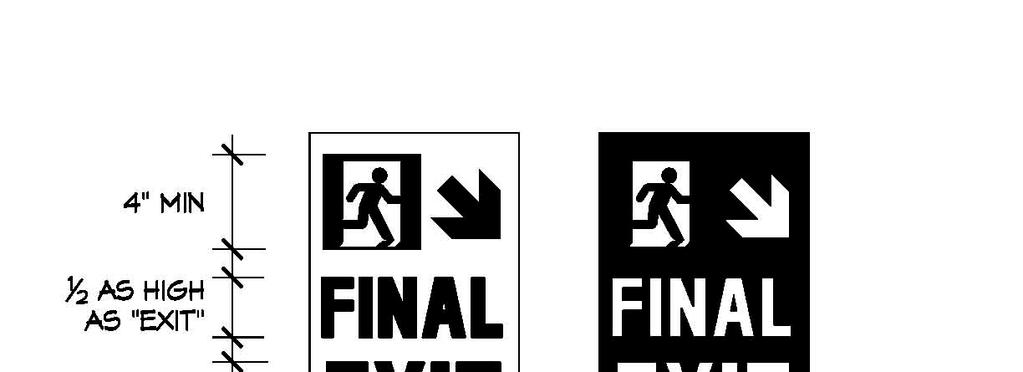
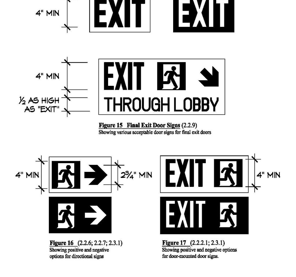
6 2.3 General standards. Intermediate exit door (fig. 13). When traveling in the egress direction, doors that lead from a vertical exit, horizontal extension in a vertical exit, horizontal exit, supplemental vertical exit, or exit passageway, but do not lead directly to the exterior or to a street level lobby are intermediate exit doors. Final exit door (fig. 14). Doors leading directly to the exterior or a street level lobby are final exit doors Door signs. A photoluminescent wall-mounted door sign complying with shall be mounted on the wall adjacent to all intermediate and final exit doors. At the final exit door, such sign shall contain supplemental directional text in sans serif letters one-half as high as the word EXIT. Examples of such texts are FINAL EXIT, or EXIT THROUGH LOBBY or EXIT TO STREET, or EXIT TO CHAMBERS STREET, etc. (see fig. 15) Door Hardware markings. Door hardware of all intermediate and final exit doors shall be marked with no less than 16 in 2 (406 mm 2 ) of photoluminescent material. This marking shall be located behind, immediately adjacent to, or on the door handle and/or escutcheon. Where a panic bar is installed, such material shall be no less than 1 (25 mm) wide for the entire length of the actuating bar or touchpad. All hardware markings covered by may include ANSI Z535.1 safety green graphics such as arrows indicating door handle turning directions, E001 or E002 emergency egress symbols as per ISO 7010, the word EXIT, the word PUSH, and similar egress-related symbols provided the minimum 16 in 2 (406 mm 2 ) of photoluminescent material is maintained Door frame markings. The top and sides of the door frame of all intermediate and final exit doors shall be marked with a solid and continuous 1" to 2" (25 mm to 51 mm) wide stripe of photoluminescent material. Gaps are permitted in the continuity of door frame markings where a line is fitted into a corner or bend, but shall be as small as practicable and in no case greater than 1 (25 mm).. Where the door molding does not provide enough flat surface on which to locate the stripe, the stripes may be located on the wall surrounding the frame. The dimensions, distances and locations of the required markings shall be consistent and uniform on all doors on the route to the exterior of the building Design of door and directional signs. Unless otherwise specified, all photoluminescent door signs and directional signs referenced herein (see figs. 11, 15, 16, 17): 1. may be either positive or negative image; 2. shall be made with the non-photoluminescent portions of the signs in safety green as per ANSI Z , American National Standard for Safety Color Code; 3. shall include three components: 3.1 the word EXIT printed in sans serif letters at least 4 high (102 mm) with strokes no less than ½ (13 mm); 3.2 an emergency exit symbol at least 4 high (102 mm), complying with E001 or E002 as per ISO 7010 ( ), Graphical Symbols Safety Colours and Safety Signs Safety Signs Used in Workplaces and Public Areas; and 3.3 an arrow at least 2 ¾ (70 mm) high, complying with E005 or E006 as per ISO Exceptions: 1. Arrows are not mandatory on door-mounted door signs required by The word EXIT is not mandatory on directional signs required by and
7 3. Additional descriptive text is permitted, provided such words are in sans serif letters and, where the word EXIT or emergency exit symbol is required on such sign, such descriptive text is no more than one-half as high as any the work EXIT or the emergency exit symbol Solid and continuous. For the purposes of this standard, solid and continuous means without gaps or interruption, except as required for the control of expansion and contraction. A series of dashes, chevrons, dots, or other similar patterns is not solid and continuous. Nonetheless, photoluminescent materials shall be considered solid and continuous if they occasionally contain the following safety green (ANSI Z535.1) symbols or text: 1) the word EXIT, 2) egress symbol E001 or E002 as per ISO 7010; 3) direction arrows E005 or E006 as per ISO 7010, or other text or symbols as approved by the Commissioner Consistent and uniform. Where markings are required to be consistent and uniform throughout the same exit, those portions of an exit in which the egress travel direction is downward may be treated differently from those portions of the same exit in which the egress travel is upward Figures. The figures annexed are intended only for illustration, and where there is a conflict between the figures and the text, the text shall govern. 2.4 Good faith prior installations. The Commissioner may accept variations to the required dimensions, distances, returns (for side edge markings), locations, and MEA labeling for buildings where: 1) photoluminescent materials were installed prior to January 1, 2005; 2) such installations meet the intent of this standard. Applications for acceptance shall indicate all deviations from this standard. The commissioner shall require documentation that the photoluminescent materials installed achieve the equivalent brightness ratings as stated in as well proof showing that the installation was completed prior to January 1, The commissioner may require installation of additional photoluminescent signs or markings in order to conform to the intent of this standard. Any such acceptance by the commissioner shall be annexed to the affidavit or report filed with the Department of Buildings pursuant to 3.3, and a copy of such report or affidavit including attachments shall be available on the premises for inspection by the Department of Buildings and Fire Department. 2.5 Installation of additional signs and markings. Where photoluminescent signs or markings are installed in locations where they are not required by 2.1 and 2.2, such signs and markings shall be MEA-approved in accordance with 1.0 (technical specifications for minimum performance). Examples of such other signs could include floor numbering signs, elevator landing signs, elevator bank indicator signs, reentry signs, etc. Where door hardware or door frame markings in accordance with or are provided at reentry doors, the reentry signs required by the building code shall be photoluminescent and MEA-approved in accordance with Other occupancies. Where photoluminescent signs or markings are installed in the exit path in other than Class E high rise buildings, such signs or markings shall comply with this standard. 3.0 Administrative filings to certify compliance 3.1 Existing buildings; Affidavit. Owners of existing buildings shall submit an affidavit of completion certifying compliance with (b) and RS 6-1, on or before July 1, 2006 for occupied buildings, or prior to issuance of a Certificate of Occupancy for new buildings under construction. In lieu of such affidavit, the owner may submit a report by an architect or engineer complying with 3.2. Such affidavit shall comply with the following:
8 3.1.1 Inspection. In such affidavit the owner shall certify that all components have been visually inspected, both with the normal lighting turned on, and with the normal and emergency lighting turned off Product identification. In such affidavit the owner shall identify the manufacturer and MEA approval number of each product installed, along with the manufacturer s product literature. The affidavit shall describe which particular products were installed in each part of the building Paints. Where in situ painting was utilized, the owner shall certify that he or she has inspected the installation and that the specified paint was utilized in accordance with the MEA-approved methods of application. 3.2 New buildings; Report. Owners of buildings filed pursuant to plans approved on or after July 1, 2006 shall submit a report of completion by an architect or engineer certifying compliance with (b) and RS 6-1, prior to issuance of a certificate of occupancy. Such report shall comply with the following: Inspection. Such report shall be submitted under controlled inspection as per Building Code The report shall certify that all components have been visually inspected, both with the normal lighting turned on and with the normal and emergency lighting turned off Product identification. Such report shall identify the manufacturer and MEA approval number of each product installed along with the manufacturer s product literature. The report shall describe which particular products were installed in which parts of the building Paints. Where in situ painting was utilized, the architect or engineer shall certify that he or she has inspected the installation and that the specified paint was utilized in accordance with the MEA-approved methods of application. 3.3 Submission of Affidavit or Report. Such affidavit or report shall be filed in duplicate with the Department of Buildings Local Law Enforcement Unit for buildings constructed pursuant to plans approved prior to July 1, 2006, and with the respective Borough Office for new buildings. A third copy of the accepted affidavit or report shall be kept and maintained on the premises for inspection by the Department of Buildings and Fire Department. Failure to have such affidavit or report available for inspection shall constitute a violation of the code. 3.4 Fire protection plans. When construction of a new building or alteration of an existing building requires that a new or amended fire protection plan be filed in accordance with section , compliance with the photoluminescent sign and marking requirements of section (b) and RS 6-1 shall be indicated in such new or amended fire protection plan. 4.0 Maintenance program. Owners shall keep the required photoluminescent signs and markings in good repair. At a minimum, owners shall, every 12 months, perform a visual inspection of the signs and marking with the normal lighting turned on. Signs and markings that are missing, damaged, loose, or that show signs of wear or missing MEA labels shall be noted and promptly repaired. The log of such inspections, including the results and any corrective measures taken, shall be kept and maintained on the premises for inspection by the Department of Buildings and Fire Department. The log shall contain the date of inspection and the printed name and signature of the person performing the inspection. Deviations from any of the requirements of this standard shall be a violation of the code.
9
10
11
12
13
14
15
16
17
18
19 EXPLANATORY MATERIAL The following are additional technical considerations for Reference Standard RS 6-1 and do not constitute a portion of the mandatory requirements. A. Activating Illumination. The products approved for use under Reference Standard 6-1 are tested in a laboratory with a fluorescent activating light source of 2 footcandles as measured on the surface of the test specimen. The measurement of 2 footcandles was derived from the minimum lighting levels as measured on the floor in exits as required by the New York City Building Code for buildings constructed after December 1, The Department of Buildings recognizes that many buildings are voluntarily providing more than 2 footcandles, and that many buildings erected before 1968 may properly be providing less. Additionally, some existing buildings are illuminated with incandescent lamps, which might not efficiently charge certain photoluminescent materials. Reference Standard 6-1 does not permit the use of lower-performing photoluminescent products for brightly-lit environments, nor does it mandate the use of higher-performing photoluminescent products for grandfathered lighting environments. Therefore, prior to choosing a product, owners are encouraged to conduct a survey of existing lighting conditions to ensure adequate performance of the photoluminescent materials selected for the particular installation. Reference Standard 6-1 relies on the current requirement of the New York City Building Code that continuous illumination be provided at all periods of building occupancy in corridors and exits 4. Over the years, on a case-by-case basis, some buildings have been approved for the installation of motion-sensor activating switches allowing dark exit stairs, with the determination made that the resulting installation was equivalent to what was then required under the code. However, such determinations were made prior to the requirement of photoluminescent materials; motion-sensor devices that reduce continuous illumination to a level below the required 2 footcandles are no longer acceptable in exits where photoluminescent materials are required. B. Dissimilar Luminance Levels Within Same Environment It is neither necessary nor possible to require that photoluminescent products in the same environment emit identical luminance levels; many factors, including the distance to the activating light source, the angle of incidence and shadows, will result in different luminance levels for identical photoluminescent products placed in the same stairway. Variations in actual luminance are expected in the same environment. However, grossly dissimilar brightness ratings within the same environment should be avoided. C. Contrasting Colors Photoluminescent material are effective in completely dark conditions, and, conversely, are usually visible in normal lighting conditions. However, in dim or semi-lit conditions, such as when batteries for an emergency light are running low or when a stair is dark but a door is open to a lighted area, the photoluminescent materials forming the outlines of steps, landing, demarcation lines, and handrails might become hard to discern. Photoluminescent materials installed adjacent to a contrasting, dark color ameliorate this effect. D. Abrasion Resistance Reference Standard 6-1 does not mandate minimum standards for abrasion resistance. For products that are to be applied to walking surfaces, it is recommended that owners consider 1) the amount of traffic in the stairs by building occupants, and 2) the products' durability and resistance to abrasion. For instance, certain thin films and paints may be sufficient where the stairs are alarmed and only used in emergencies. However, where the occupants use the stairs on a daily basis, more durable products should be considered. Ultimately, the building owner is responsible for maintaining the photoluminescent materials in accordance with Reference Standard 6-1, Section As such terms are defined in the Building Code of the City of New York
20 E. Adhesives. Reference Standard 6-1 does not specify the adhesives to be used. The choice of adhesive should be carefully considered for the longevity of the installation, particularly if the surface to which the product to be applied is porous, uneven, or subject to temperature or humidity variation. At a minimum owners should follow the manufacturers instructions. F. Slip-resistance. Reference Standard 6-1 does not specify minimum slip-resistance requirements for photoluminescent products installed on walking surfaces. Whether or not a particular building s egress path is subject to any slipresistance requirements may depend on the original date of construction. Any photoluminescent materials installed should be as slip-resistant as the minimum standard that is applicable to the building in which they are being installed. A stripe of photoluminescent material that is not slip-resistant may, depending on the design of the stair nosing product, be compensated for by the inclusion of an adjacent, slip-resistant strip. G. Wall-mounted floor perimeter markings at doors. In deciding whether to continue a wall-mounted demarcation line across a door or to transition to the floor ( ), consideration should be given to how the door is used or secured so as to avoid the possibility that the demarcation line on the door, if left open, might lead evacuees into a non-egress space or area. Reference Standard RS 6-1A Additional Standards as Required by Reference Standard RS 6-1 for Photoluminescent exit path markings Specimens to be tested shall be finished products as they would be sold to purchasers. Each distinct product material shall be separately tested and receive its respective test results for its respective Materials, Equipment and Acceptance (MEA) Division approval number. However, variation in the size of the product and differences in the text or arrow directions, etc., shall not constitute a distinct product material, but shall constitute a different model number provided that product literature describing with pictorial representations of all such model numbers associated with the test specimens is submitted to MEA. Thin gauge films and paints shall be tested when applied to a rigid cement board ¼ thick. In the case of paints, such painted test specimens shall be submitted along with the description of the procedures used to produce the test specimens (such as surface preparation, primer coats, number of photoluminescent coats, encapsulant coat if applicable, maximum/minimum temperature or humidity during painting if applicable, etc.). Such description shall be included in the laboratory s test report; and such description shall be included in the MEA resolution as the mandatory labeling on the paint cans as instructions to purchasers. 1.0 Brightness Rating ISO 17398:2004, Safety Colours and Safety Signs Classification, Performance and Durability of Safety Signs, Clause Three specimens shall be tested (separately for each distinct product material). Thin gauge films and paints shall be tested when applied to a rigid cement board ¼ thick. The testing shall be in accordance with ISO 17398, clause 7.11, with the following modifications: 1.1 Clause Excitation Light Conditions. The test established in Clause for classification of photoluminescent materials in accordance with Clause 5.5 is not required. The test in Clause is required, however subclauses a), b), and c) are replaced with the following excitation standard: "Excitation of the phosphorescent test specimens shall be by a 4000K to 4500 K fluorescent light providing a mean illuminance of 2 footcandles (21.6 lux) on the surface of the test specimen. The excitation duration shall be 2 hours."
21 1.2 Clause Luminance Instrumentation. This Clause describes two luminance instrumentation options. For this Reference Standard 6-1A, the contact luminance meter option shall be limited only to test specimens that are both smooth and flat. 1.3 Clause Luminance recordings for classification purposes. This Clause is not required. 1.4 Clause Luminance recordings for product description purposes. The luminance performance shall be based on the mean values of the three test specimens measured at 10 minutes, the mean values of the three test specimens measured at 60 minutes, and the mean values of the three test specimens measured at 90 minutes. The resulting luminance performances shall constitute a "brightness rating", which shall be indicated in the test report. The minimum brightness rating shall be 30.0 mcd/m 2 at 10 minutes, 7.0 mcd/m 2 at 60 minutes, and 5.0 mcd/m 2 at 90 minutes. For example, a product that minimally meets the luminance levels would have a brightness rating of Washability ASTM D (2003), Standard Test Methods for Practical Washability of Organic Coatings. 2.1 Three specimens (of each distinct product material) shall be tested for each soil/staining medium in accordance with ASTM D Thin gauge films and paints shall be tested when applied to a rigid cement board ¼ thick. 2.2 The laboratory shall prepare the soils and staining media that shall include: crayon, waterborne felt-tipped pen, lipstick, and a mineral-oil-bourne soilants as outlined in clause The cleaning media shall include liquid household cleansers available at supermarkets or laboratory-standardized liquid cleansers as outlined in clause After completion of the test, each specimen shall be rated at 5 or greater in accordance with clause Toxicity Bombardier SMP 800-C (Rev. 4, 11/1/2000) Toxic Gas Generation Test. One test specimen (of each distinct product material) shall be tested in each of the flaming and non-flaming modes in accordance with SMP 800-C. Where the test specimen is narrower than the required 3" x 3" (76 mm x 76 mm), more than one test specimens shall be placed next to each other to provide 9 in 2 (229 mm 2 ) of surface area. Thin gauge films and paints shall be tested when applied to a rigid cement board ¼ thick. The testing shall be in accordance with SMP 800-C, with the following modifications: 3.1 Clause 4.3 For determining the concentration of the toxic gases in accordance with the referenced Boeing BSS 7239 specification, the Commissioner may accept a procedure that uses gas detection tubes or other procedures, in lieu of the absorptive sampling procedure, provided that the testing laboratory outlines the procedures in its report and certifies that equivalent results are obtained. 3.2 Clause 5.0 In accodance with the Building Code and departmental rules, the Department of Buildings Materials, Equipment and Acceptance Division may approve any testing laboratory it deem qualified to perform this test. EXCEPTION: For photoluminescent products that, when installed, provide coverage exceeding the limits of interior trim, such products shall instead be tested for toxicity as interior finishes and/or interior floor coverings if and as required by Building Code (e) and/or Tread nosings with a horizontal depth of 4 or less and that contain a photoluminescent stripe may be tested in accordance with RS 6-1A. 4.0 Radioactivity ASTM D , Standard Practices for the Measurement of Radioactivity. 4.1 Three test specimens (of each distinct product material) shall be tested in accordance with ASTM D Thin gauge films and paints shall be tested when applied to a rigid cement board.
22 4.2 The activity of the test specimens shall be shown to be statistically indistinguishable from background. 4.3 Alpha and beta activity shall be measured on a test specimen of at least 1 in x 1 in (25.4 mm x 25.4 mm) and counted using a proportional counter for a minimum of 15 minutes. 4.4 Gamma activity shall be measured on the same test specimen using a gamma spectrometer counted for at least 1 hour. 5.0 Flame Spread either one of the following two standards: 5.1 ASTM E , Standard Test Method for Surface Flammability of Materials Using a Radiant Heat Energy Source Four test specimens (of each distinct product material) shall be tested in accordance with ASTM E 162. Where the test specimen is narrower than required by the test, several pieces may be grouped together to provide the necessary surface area. Thin gauge films and paints shall be tested when applied to a rigid cement board ¼ thick The specimens shall have a flame spread index (ls) not to exceed ASTM D , Standard Test Method for Rate of Burning and/or Extent and Time of Burning of Plastics in a Horizontal Position Ten test specimens shall be prepared for use in accordance with ASTM D The test specimens shall not burn beyond the 25 mm reference mark. EXCEPTION: For photoluminescent products that, when installed, provide coverage exceeding the limits of interior trim, such products shall instead be tested for flame spread and smoke density as interior finishes and/or interior floor coverings if and as required by Building Code (c) and (d) and/or Tread nosings with a horizontal depth of 4 or less and that contain a photoluminescent stripe may be tested in accordance with RS 6-1A. 6.0 UV Degradation ("UV") (only where a "UV" rating is requested for exterior weather conditions or unfiltered sunlight applications) ASTM G , Standard Practice for Operating Xenon Arc Light Apparatus for Exposure of Nonmetallic Materials. 6.1 Three specimens (of each distinct product material) shall be tested for a period of 1000 hours in accordance with ASTM G 155. The specimens shall be subjected to Cycle 1 exposure condition noted in Table x3.1 of such standard. Thin gauge films and paints shall be tested when applied to a rigid cement board ¼ thick. 6.2 The testing laboratory that conducted the weathering test shall certify that none of the following surface characteristics exist when viewed under a minimum of 5x magnification: cracking, checking, crazing, or erosion. 6.3 After conclusion of the testing, such laboratory shall directly send the specimens to the testing laboratory that conducted the brightness rating tests in The brightness rating testing laboratory shall perform luminance tests as per 1.0 on the weathered specimens and report the results. The specimens shall indicate at least 90% of the original brightness at 10 minutes, at least 90% of the original brightness at 60 minutes, and at least 90% of the original brightness at 90 minutes, as compared to the brightness ratings prior to the weathering test.
23 STATEMENT OF BASIS AND PURPOSE: The September 11 th terrorist attacks and subsequent collapse of the World Trade Center (WTC) Twin Towers and building number 7 WTC were a national tragedy that had an enormous impact on New York City, more than the obvious physical damage. Before 9/11, New York City was commonly acknowledged to have one of the most stringent building codes in the United States. The aftermath of these attacks caused us to rethink our codes in relation to high-rise building safety. The lessons learned from the tragedy had a practical application for improvements to our codes. To that end, the New York City Department of Buildings convened the World Trade Center Building Code Task Force (Task Force) to review current building design, construction and operating requirements for high rise office buildings, and to determine if modifications were needed to enhance public safety. The Task Force brought together a broad coalition of affected groups, including experts from both the public and private sectors (government, academia and industry) and survivors of the attacks. It was this deliberate consensus building that ensured the success of the Task Force. In February 2003, the Task Force released its findings (available at recommending changes to the way that high-rise office buildings are designed and how they function during an extreme event. The Task Force focused its efforts in four main areas: structural strength, evacuation and egress, fire protection, and mechanical systems. The resulting recommendations serve public safety and are realistic and practicable. Thirteen of these recommendations were signed into law on June 24, 2004 by Local Law 26 of 2004, which amended the New York City Building Code and Fire Prevention Code. One component of Local Law 26 or 2004 mandates the retroactive installation of photoluminescent signs and markings in high rise office buildings on or before July 1, 2006, and requires that the Commissioner of Buildings adopt a reference standard establishing the technical standards for the installation and placement of the standards on of before January 1, This proposed Reference Standard RS 6-1 and 6-1A establish the technical standards for the installation of photoluminescent building signs in compliance with Local Law 26 of 2004.
CONSTRUCTION TECHNOLOGY UPDATE
 CONSTRUCTION TECHNOLOGY UPDATE No. 78, September 2011 Building Egress Using Photoluminescent Markings by Noureddine Benichou and Guylene Proulx The use of photoluminescent material systems in buildings
2009 IBC Section 1024 Approved Luminous Egress Path Markings
 2009 IBC Section 1024 Approved Luminous Egress Path Markings Where Required Buildings of Groups A (Assembly), B (Business), E (Education), I (Institutional), M (Mercantile) and R-1 (Residential transient
PSA / PSPA Guide to the Use of Photoluminescent Safety Markings. Part One: Egress Markings In Stairwells
 PSA / PSPA Guide to the Use of Photoluminescent Safety Markings Part One: Egress Markings In Stairwells August 2008 1 Forward The foundation of this guide is based on a recommendation submitted to the
BRADYGLO EMERGENCY EGRESS MARKING HANDBOOK
 BRADYGLO EMERGENCY EGRESS MARKING HANDBOOK BRADYGLO EMERGENCY EGRESS MARKING HANDBOOK Table of Contents Introduction to Code Changes...2 2009 International Building Code and International Fire Code...3
SPECIFICATIONS Aluminum Stair Nosing - Bull Nosing
 2009 IBC/IFC Aluminum Stair Tread Aluminum Stair Nosing - Bull Nosing ITEM NO: BPL307BNA Width 2.169, Specify Custom Length up to 12 Anti-skid stair tread marking, intended for indoor and outdoor. Apply
Design Aid for Barrier-Free Accessibility in Existing Buildings
 Design Aid for Barrier-Free Accessibility in Existing Buildings July 9, 2004 Table of Contents 1. Introduction 1 2. References 2 3. Access to the Building 2.1 Site Accessibility 2 4. Building Access 3.1
THE JALITE 7010 EXIT SIGN SYSTEM LIT effective, efficient and elegant, exit identification solutions designed to save lives.
 THE JALITE 7010 EXIT SIGN SYSTEM LIT543-12.06.2012 effective, efficient and elegant, exit identification solutions designed to save lives. 7010 Sign System 1: Ceiling mounted rod option Introducing the
Work Group Item Stairways serving an occupant load of less than 50 shall have a width of not less than 36 inches (914 mm).
.") IBC-12/13 1009.1, 1009.4, 1009.7.2, 1009.7.4, 1009.8, 1009.10, 1009.15 (IFC [B] 1009.1, 1009.4, 1009.7.2, 1009.7.4, 1009.8, 1009.10, 1009.15) Proponent: S. Bajnai, Chesterfield County, VA, ICC Building
IBC-12/13 1009.1, 1009.4, 1009.7.2, 1009.7.4, 1009.8, 1009.10, 1009.15 (IFC [B] 1009.1, 1009.4, 1009.7.2, 1009.7.4, 1009.8, 1009.10, 1009.15) Proponent: S. Bajnai, Chesterfield County, VA, ICC Building
STEP GLOW. A Step ahead
 STEP A Step ahead NO STEP- - Lights on STEP- Visual guidance products offer the the most advanced photoluminescent technology available today. Bright & Long Lasting, STEP- is over 80% brighter then ASTM
Section 1 OBC FADS /13 Access to Parking Areas
 Section 1 OBC 3.8.2.2 4.3.12/13 Access to Parking Areas A barrier-free path of travel is provided from: a) the entrance to the exterior parking area b) at least one parking level where a passenger elevator
ICC CODE CORNER 2012 IFC Code & Commentary
 SECTION 1005 MEANS OF EGRESS SIZING [B] 1005.1 General. All portions of the means of egress system shall be sized in accordance with this section. Exception: Means of egress complying with Section 1028.
Project Address Applicant: (Please Print) Plan review Engineer: Phone: Date
 Plan review Engineer: Phone: Date") BUILDING AND SAFETY Tenant Improvement Checklist Project Address Applicant: (Please Print) Plan review Engineer: Phone: Date APPLICATION The following items will be required at the permit counter before
BUILDING AND SAFETY Tenant Improvement Checklist Project Address Applicant: (Please Print) Plan review Engineer: Phone: Date APPLICATION The following items will be required at the permit counter before
The Building Codes A.R.E. Building Design and Construction Exam Prep
 Know Thy Codes! The Building Codes Building Codes The Code of Hammurabi 4000bc Developed 19 th and 20 th c. Codes define what you can and can t do Allowable area and height based on degree of danger Fire
EGRESS CHAPTER ,500 3 Over 2,500 4 OCCUPANT LOAD REQUIRED MEANS OF EGRESS
 CHAPTER 4 EGRESS SECTION 401 GENERAL 401.1 General. The means of egress for new bleachers, folding and telescopic seating, and grandstands shall comply with this chapter. SECTION 402 TRAVEL 402.1 Exit
ICC CODE CORNER 2012 IFC Code & Commentary
 Chapter 10: Means of Egress General Comments The general criteria set forth in Chapter 10 regulating the design of the means of egress are established as the primary method for protection of people in
JC Code & Construction Consultants, Inc. Advanced 2010 FBC Update Ch. 1 to 16
 JC Code & Construction Consultants, Inc. Advanced 2010 FBC Update Ch. 1 to 16 Welcome! This course is designed to provide an overview of the most significant changes to the 2010 edition of the Florida
2015 IBC Accessible Means of Egress
 2015 IBC Accessible Means of Egress Based on the 2015 International Building Code Description Upon completion, the participant will be able to apply the accessible means of egress provisions of Section
First Revision No NFPA [ Section No ]
![First Revision No NFPA [ Section No ]](/thumbs/72/67132364.jpg "First Revision No NFPA [ Section No ]") National Fire Protection Association Report of 13 http://submittals.nfpa.org/terraviewweb/contentfetcher?commentpara... 10/28/2015 10:35 AM First Revision No. 5501-NFPA 5000-2015 [ Section No. 3.3.220.4
National Fire Protection Association Report of 13 http://submittals.nfpa.org/terraviewweb/contentfetcher?commentpara... 10/28/2015 10:35 AM First Revision No. 5501-NFPA 5000-2015 [ Section No. 3.3.220.4
APPENDIX B SIGNAGE STANDARDS
 APPENDIX B SIGNAGE STANDARDS Post-merger, The University of Toledo has two signage design specifications. The former "Black & White" signage system (described in Part 1) is being phased out and gradually
PRESCRIPTIVE COMPLIANCE METHOD
 CHAPTER PRESCRIPTIVE COMPLIANCE METHOD 3 SECTION 301 GENERAL 301.2 Building materials. Building materials shall comply with the requirements of this section. 301.2.1 Existing materials. Materials already
INTERIOR FINISHES CHAPTER 8
 CHAPTER 8 INTERIOR FINISHES SECTION 801 GENERAL 801.1 Scope. Provisions of this chapter shall govern the use of materials used as interior finishes, trim and decorative materials. 801.1.1 Interior finishes.
APPLICATION NUMBER:, TAX MAP KEY: STREET ADDRESS:, PRPOJECT: APPLICANT:, PHONE NO: MAILING ADDRESS:, FAX NO:
 COUNTY OF KAUAI BUILDING DIVISION, DEPARTMENT OF PUBLIC WORKS 4444 RICE STREET, SUITE 175, LIHUE, HAWAII 96766 Telephone: (808) 241-6655 Fax Number: (808) 241-6806 BUILDING CODE COMMERCIAL CHECKLIST APPLICATION
2007 Title 24 Accessibility Code Updates and ADA Issues
 2007 Title 24 Accessibility Code Updates and ADA Issues C.A.S.H. Workshop June 2007 Introduction Update on ADA Certification of the California Building Code Overview of significant changes to accessibility
2600SEG135 SAFETY STANDARD FOR INDUSTRIAL LADDERS AND STAIRCASES IN BUILDINGS
 1.0 OBJECTIVE The purpose of this standard is to establish the minimum requirements applicable to standard ladders and staircases of general use in buildings and industrial installations of the Panama
2015 IBC Exit Systems
 Objectives 2015 IBC Exit Systems Based on the 2015 International Building Code Upon completion, participants will be better able to: Determine those means of egress components that are defined as exits
Florida Accessibility Code for Building Construction
 Florida Accessibility Code for Building Construction Accessibility Training Course Florida Building Commission Introduction Course will review the Florida Accessibility Code for Building Construction as
First Revision No NFPA [ Section No ]
![First Revision No NFPA [ Section No ]](/thumbs/79/80122011.jpg "First Revision No NFPA [ Section No ]") National Fire Protection Association Report of 17 http://submittals.nfpa.org/terraviewweb/contentfetcher?commentpara... 10/21/2015 9:28 AM First Revision No. 4502-NFPA 101-2015 [ Section No. 3.3.92.4 ]
National Fire Protection Association Report of 17 http://submittals.nfpa.org/terraviewweb/contentfetcher?commentpara... 10/21/2015 9:28 AM First Revision No. 4502-NFPA 101-2015 [ Section No. 3.3.92.4 ]
DIVISION 10 SPECIALTIES
 DIVISION 10 SPECIALTIES A. INTERIOR SIGNAGE 1. Each room number shall be displayed with a wall mounted sign that is not less than 6 square placed 60" from its center to the finished floor and adjacent
INTERIOR FINISHES CHAPTER 8
 CHAPTER 8 INTERIOR FINISHES SECTION 801 GENERAL 801.1 Scope. Provisions of this chapter shall govern the use of materials used as interior finishes, trim and decorative materials. 801.2 Interior wall and
Master Specification WALLTITE Eco v.3 by BASF Canada Inc. Section SPRAY POLYURETHANE FOAM INSULATION Page 1
 Page 1 WALLTITE ECO v.3 by BASF Canada Inc, is a thermal insulation intended for building enclosures, located in appropriate assembly locations in buildings during enclosure construction. This section
Florida Accessibility Code for Building Construction
 Florida Accessibility Code for Building Construction Accessibility Training Course Florida Building Commission 1 Introduction Course will review the Florida Accessibility Code for Building Construction
COMMUNITY RISK REDUCTION BUREAU MANUAL CODE REQUREMENTS TEMPORARY TENTS AND MEMBRANE STRUCTURES EFFECTIVE: APRIL 1, 2016 AUTHORIZED: R.
 COMMUNITY RISK REDUCTION BUREAU MANUAL CODE REQUREMENTS 423.7 TEMPORARY TENTS AND MEMBRANE STRUCTURES EFFECTIVE: APRIL 1, 2016 AUTHORIZED: R. Pearce SCOPE This policy applies to temporary tents, air-supported,
ACCESSIBLE REST ROOM Code Requirements
 ACCESSIBLE REST ROOM Code Requirements Applicable Code References (Effective December 31, 2005) (Amendments effective August 1, 2009) 2003 International Building Code portion of the 2005 State Building
Code Requirements for Existing Buildings. R. W. Sullivan, Inc. 529 Main St., Suite 203 Charlestown, MA (617)
") Code Requirements for Existing Buildings R. W. Sullivan, Inc. 529 Main St., Suite 203 Charlestown, MA (617) 523-8227 www.rwsullivan.com R.W. Sullivan Engineering (RWS) was established in 1945 and currently
Code Requirements for Existing Buildings R. W. Sullivan, Inc. 529 Main St., Suite 203 Charlestown, MA (617) 523-8227 www.rwsullivan.com R.W. Sullivan Engineering (RWS) was established in 1945 and currently
City of Walnut Creek Development Review Services 1666 N. Main Street, Walnut Creek, CA (925) phone (925) fax
 phone (925) fax") City of Walnut Creek Development Review Services 1666 N. Main Street, Walnut Creek, CA 94596 (925) 943-5834 phone (925) 256-3500 fax Issued August 3, 2011 Information Bulletin No. IB-002 Submittal Requirements
City of Walnut Creek Development Review Services 1666 N. Main Street, Walnut Creek, CA 94596 (925) 943-5834 phone (925) 256-3500 fax Issued August 3, 2011 Information Bulletin No. IB-002 Submittal Requirements
PRESCRIPTIVE COMPLIANCE METHOD
 CHAPTER 3 PRESCRIPTIVE COMPLIANCE METHOD [B] SECTION 301 GENERAL 301.1 Scope. The provisions of this chapter shall control the alteration, repair, addition and change of occupancy of existing structures,
How to Prepare Your LSE Report
 LSE Rule Category Required Documentation Information Comments / Applicable Code Sections/ 10.1 Building Height Provide the Building height in Feet Provide the number of stories above grade Helpful Hints
2012 IBC Exit Systems
 Accreditation Based on the 2012 International Building Code The International Code Council has been accredited as an Authorized Provider by the International Association for Continuing Education and Training
TENTS AND OTHER MEMBRANE STRUCTURES
 CHAPTER 31 TENTS AND OTHER MEMBRANE STRUCTURES SECTION 3101 GENERAL 3101.1 Scope. Tents and membrane structures shall comply with this chapter. The provisions of Section 3103 are applicable only to temporary
IFC/IBC, NYC LL 26/141 and NFPA Compliant Guidance Systems
 Photoluminescent Emergency Path-Finding Solutions for Outdoor and Indoor Use IFC/IBC, NYC LL 26/141 and NFPA Compliant Guidance Systems WWW.US.ECOGLO.COM OUR MISSION Our mission at Ecoglo Inc. is to manufacture
DEPARTMENT OF PUBLIC SAFETY AND CORRECTIONS. Public Safety Services ADA-ABA COMMENT ASSISTANCE GUIDE
 DEPARTMENT OF PUBLIC SAFETY AND CORRECTIONS BOBBY JINDAL GOVERNOR Public Safety Services H. BUTCH BROWNING STATE FIRE MARSHAL ADA-ABA COMMENT ASSISTANCE GUIDE The information submitted is not sufficient
HCD DSA OSHPD 1 2 1/AC AC SS SS/CC CALIFORNIA BUILDING CODE 301
 CALIFORNIA BUILDING CODE MATRIX ADOPTION TABLE CHAPTER 8 INTERIOR FINISHES (Matrix Adoption Tables are non-regulatory, intended only as an aid to the user. See Chapter 1 for state agency authority and
CITY OF LOS ANGELES Department of Building and Safety Disabled Access Section RESIDENTIAL ACCESSIBILITY PLAN REVIEW LIST
 GENERAL PROJECT INFORMATION PERMIT APPLICATION # PLAN CHECK NO JOB ADDRESS CITY ZIP REVIEWED BY PHONE DATE NOTE: Numbers in the parenthesis ( ) refer to sections of the 2014 edition of the Los Angeles
TEXAS DEPARTMENT OF TRANSPORTATION GENERAL SERVICES DIVISION SIGN FACE, ROLL-UP, REFLECTIVE, CONSTRUCTION AND WORK ZONE PUBLICATION
 TEXAS DEPARTMENT OF TRANSPORTATION GENERAL SERVICES DIVISION SPECIFICATION NO. * SIGN FACE, ROLL-UP, REFLECTIVE, CONSTRUCTION AND WORK ZONE PUBLICATION This specification is a product of the Texas Department
IWF Safety Guidelines
 2018 The purpose for the display rules and height restrictions is to provide visibility to all exhibitors. At the same time, these regulations should maintain the inherent benefits of differing exhibit
Countertops and Cabinets
 Countertops and Cabinets 5.1 Laminated countertop has developed a bubble. Laminated countertops shall not have localized bumps or swells. Countertops not meeting the acceptable performance condition shall
HILLSBOROUGH TOWNSHIP CODE ENFORCEMENT
 HILLSBOROUGH TOWNSHIP CODE ENFORCEMENT SAMPLE GUIDE FOR RESIDENTIAL DECKS revised 7 16 Call before you dig! 1 800 272 1000 New Jersey One Call. Utility Mark Out. THIS GENERIC GUIDE IS NOT ALL INCLUSIVE
CITY OF FORTUNA, CALIFORNIA
 CITY OF FORTUNA, CALIFORNIA Community Development Department Building and Safety Division 621 11 th street Fortuna, California 95540 Phone: 707-725-7600 - Fax: 707-725-7610 ACCESSIBLE PARKING REQUIREMENTS
ENGINEERING SPECIFICATION FIBERTRED MOLDED STAIR TREADS SECTION 06610
 ENGINEERING SPECIFICATION FIBERTRED MOLDED STAIR TREADS SECTION 06610 PART 1 - GENERAL 1.1 SCOPE OF WORK FIBERGLASS REINFORCED PLASTICS (FRP) FABRICATIONS MOLDED STAIR TREADS A. The CONTRACTOR shall furnish,
INTERIOR FINISHES CHAPTER 8
 CHAPTER 8 INTERIOR FINISHES SECTION 801 GENERAL 801.1 Scope. Provisions of this chapter shall govern the use of materials used as interior finishes, trim and decorative materials. 801.2 Interior wall and
2015 International Fire Code
 1001, 1001.1, 1001.2, 1002, [BE] 1002.1, 1003, [BE] 1003.1, [BE] 1003.2, [BE] 1003.3, [BE] 1003.3.1, [BE] 1003.3.2, [BE] 1003.3.3, [BE] 1003.3.4, [BE] 1003.4, [BE] 1003.5, [BE] 1003.6, [BE] 1003.7, 1004,
SECTION IMPACT RESISTANT WALL PROTECTION
 SECTION 10265 PART I - GENERAL 1.01 DESCRIPTION A. Scope: Work under this Section shall include all materials and installation necessary to provide Impact-Resistant Wall Protection including Wall guards,
SECTION ACCORDION FOLDING PARTITIONS
 PART 1 - GENERAL 1.1 DESCRIPTION: SECTION 10 22 26.13 ACCORDION FOLDING PARTITIONS SPEC WRITER NOTE: Delete between // // if not applicable to project. Also delete any other item or paragraph not applicable
INTERIOR ENVIRONMENT
 CHAPTER 12 INTERIOR ENVIRONMENT > SECTION 1201 GENERAL 1201.1 Scope. The provisions of this chapter shall govern ventilation, temperature control, lighting, yards and courts, sound transmission, room dimensions,
NOTES FOR THE PERFORMANCE BASED SPECIFICATION FOR TRAFFIC SIGNS
 CONTENTS NOTES FOR THE PERFORMANCE BASED SPECIFICATION FOR TRAFFIC SIGNS 1. SCOPE... 2 2. RELATED DOCUMENTS... 2 3. DEFINITIONS... 2 4. COMPLIANCE... 2 5. SIGN FACE DESIGN... 3 6. VISIBILITY... 3 6.1 Performance
Proudly Made in the U.S.A.
 5-Year Warranty Proudly Made in the U.S.A. Cast-In-Place (wet-set) 2 Cast-In-Place (wet-set) Tactile Proudly Made in the U.S.A. In stock colors White 37875 Brick Red 20109 Yellow 33538 Blue 15187 Safety
SECTION RESILIENT SHEET FLOORING
 SECTION 09 65 16 RESILIENT SHEET FLOORING SPEC WRITER NOTE: Delete text between // // not applicable to project. Edit remaining text to suit project. PART 1 - GENERAL 1.1 SUMMARY A. Section Includes: 1.
9/20/2016 4:01 PM. Second Revision No NFPA [ New Section after ] Submitter Information Verification. Committee Statement
![9/20/2016 4:01 PM. Second Revision No NFPA [ New Section after ] Submitter Information Verification. Committee Statement](/thumbs/79/79682106.jpg "9/20/2016 4:01 PM. Second Revision No NFPA [ New Section after ] Submitter Information Verification. Committee Statement") of 28 9/20/2016 4:01 PM Second Revision No. 5502-NFPA 101-2016 [ New Section after 36.2.1.5 ] 36.2.1.6 Grab Bars for Bathtubs, Bathtub-Shower Combinations, and Showers. 36.2.1.6.1 Where bathtubs, bathtub-shower
of 28 9/20/2016 4:01 PM Second Revision No. 5502-NFPA 101-2016 [ New Section after 36.2.1.5 ] 36.2.1.6 Grab Bars for Bathtubs, Bathtub-Shower Combinations, and Showers. 36.2.1.6.1 Where bathtubs, bathtub-shower
Supported Scaffold Inspections
 Supported Scaffold Inspections May 2016 Inspect scaffolds and scaffold parts daily, before each work shift, and after any event that may have caused damage. Check to see if power lines near scaffolds are
HERMIT S REST GRAND CANYON NATIONAL PARK BUILDING CODE REVIEW
 HERMIT S REST GRAND CANYON NATIONAL PARK BUILDING CODE REVIEW 27 September 2007 prepared by: J. CHRIS EVANS ARCHITECT 3220 E. Terra Alta Blvd. No. 9 Tucson, Arizona 85716 520.319.8835 evansarch@hotmail.com
Code Compliance Research Report CCRR-0185
 Code Compliance Research Report CCRR-0185 Issue Date: 12-09-2016 Renewal Date: 12-10-2017 Revision Date: 04-20-2017 DIVISION: 06 00 00 WOOD, PLASTICS, AND COMPOSITES Section: 06 50 00 Structural Plastics
Innovation Superior performance Durability Exceptional value Kinesik Engineered Products Incorporated
 R VISIBLY BETTER Innovation Superior performance Durability Exceptional value Kinesik Engineered Products Incorporated www.kinesik.ca Kinesik Engineered Products Incorporated is a global leader of products
780 CMR CHAPTER 34 EXISTING BUILDINGS STRUCTURES
 780 CMR CHAPTER 34 EXISTING BUILDINGS STRUCTURES SECTION 3401 GENERAL 3401.1 Scope. Chapter 34 of the International Building Code 2009 is deleted in its entirety. The provisions of the International Existing
May 8, 2017 ADDENDUM #1. IFB Resin Floor System For Highway Department Central District Building
 May 8, 2017 ADDENDUM #1 IFB 17-082 Resin Floor System For Highway Department Central District Building Addendum #1 is being issued to offer an alternate resin flooring system. 096700 FLUID-APPLIED FLOORING
TRIDENT SEC 04 SECTION SAFETY AND SECURITY FILMS
 TRIDENT SEC 04 SECTION 08 87 23 SAFETY AND SECURITY FILMS PART 1 GENERAL 1.1 SUMMARY A. Optically clear, anti-fragmentation protective polymeric film for glass hazard mitigation. 1.2 RELATED SECTIONS A.
Stairs have many potential violations this Newsletter is Part 1 of two parts.
 Stairs have many potential violations this Newsletter is Part 1 of two parts. Violation 1 : Risers do not meet requirements: riser heights too high/low; too much variation between riser heights; risers
Division 09 FINISHES TABLE OF CONTENTS
 Division 09 FINISHES TABLE OF CONTENTS 09 1000 GENERAL... 3 A. RELATED SECTIONS... 3 B. MAINTENANCE OF FINISHES... 3 C. PUBLIC AREAS... 3 D. CUTTING AND PATCHING... 3 E. CLEANING... 3 F. RECOMMENDED FLOORING
Student Services & Classroom Addition
 SECTION 095133 - ACOUSTICAL METAL PAN CEILINGS PART 1 - GENERAL 1.1 RELATED DOCUMENTS A. Drawings and general provisions of the Contract, including General and Supplementary Conditions and Division 01
DEPARTMENT OF LICENSING AND REGULATORY AFFAIRS CONSUMER AND INDUSTRY SERVICES DIRECTOR S OFFICE BUREAU OF SAFETY AND REGULATION
 DEPARTMENT OF LICENSING AND REGULATORY AFFAIRS CONSUMER AND INDUSTRY SERVICES DIRECTOR S OFFICE BUREAU OF SAFETY AND REGULATION GENERAL INDUSTRY SAFETY AND HEALTH STANDARD GENERAL INDUSTRY SAFETY STANDARDS
BUILDING CODE VARIANCE
 BUILDING CODE VARIANCE April 2009 06-BCV-011-R1 Page 1 of 8 DISCUSSION MULTI-LEVEL STORAGE RACKING SYSTEMS The Alberta Building Code 2006 contains no specific requirements for multi-level storage racking
Newton Group CANADACAR SYSTEM. Basic Construction of the CANADACAR System. CANADACAR Module Format
 Basic Construction of the CANADACAR System The CANADACAR System is a prefabricated, engineered and constructed freestanding parking garage structure that utilizes superior technology combining pre-cast
2003 International Residential Building Code
 2003 International Residential Building Code Section R305 Ceiling Height Habitable rooms, hallways, corridors, bathrooms, toilet rooms, laundry rooms and basements shall have a ceiling height of not less
Reliant Holdings Ltd Safety Management System
 Preparation: Safety Mgr Authority: President Issuing Dept: Safety Page: Page 1 of 7 Purpose The purpose of this program is to prevent injuries due to falls from elevated work areas and ensure employees
SECTION ELEVATED BLEACHERS (Angle Frame Semi-Closed Deck)
") SECTION 13125 ELEVATED BLEACHERS (Angle Frame Semi-Closed Deck) PART 1 GENERAL 1.1 RELATED DOCUMENTS A. Drawings and general provisions of the Contract, including General and Supplementary Conditions and
SECTION 13125 ELEVATED BLEACHERS (Angle Frame Semi-Closed Deck) PART 1 GENERAL 1.1 RELATED DOCUMENTS A. Drawings and general provisions of the Contract, including General and Supplementary Conditions and
SECTION GYPSUM BOARD ASSEMBLIES
 SECTION 09 21 16 GYPSUM BOARD ASSEMBLIES PART 1 GENERAL 1.1 SECTION INCLUDES A. Metal stud wall and ceiling framing, 20 gauge. B. Metal channel suspended ceiling framing. C. Gypsum board. D. Gypsum sheathing.
ADA APPROVED SURFACE APPLIED DETECTABLE WARNING SYSTEM
 ADA APPROVED SURFACE APPLIED DETECTABLE WARNING SYSTEM PART 1 GENERAL 1. RELATED DOCUMENTS A. Drawings and general provisions of Contract, including General and Special Conditions, apply to this Section.
B. Samples for Initial Selection: For each type of impact-resistant wall protection unit indicated.
 SECTION 102600 - WALL AND DOOR PROTECTION PART 1 - GENERAL 1.1 RELATED DOCUMENTS A. Drawings and general provisions of the Contract, including General and Supplementary Conditions and Division 01 Specification
LYNN BUILDING DEPT. TABLE OF CONTENTS SECTION 1:00 APPLICABILITY PAGE 1 SECTION 2:00 GENERAL DEFINITIONS PAGE 1, 2 & 3
 (. TABLE OF CONTENTS LYNN BUILDING DEPT. SECTION 1:00 APPLICABILITY PAGE 1 SECTION 2:00 GENERAL DEFINITIONS PAGE 1, 2 & 3 SECTION 3:00 GENERAL REGULATIONS PAGE 3 & A SECTION A:00 PROHIBITED SIGNS PAGE
MASTER SIGN PLAN BRADFORD
 MASTER SIGN PLAN 14-MSP-001 BRADFORD Unless exempt from regulation per Cary s Land Development Ordinance (LDO), a sign permit is required prior to the installation of all wall and ground signs. MSP identifier:
TRIDENT S8 DN 35 SECTION SAFETY AND SECURITY FILMS
 TRIDENT S8 DN 35 SECTION 08 87 23 SAFETY AND SECURITY FILMS PART 1 GENERAL 1.1 SUMMARY A. Optically clear, anti-fragmentation protective polymeric film for glass hazard mitigation. 1.2 RELATED SECTIONS
Visual Interpretation Of The
 Visual Interpretation Of The N T E R N A T I O N A L E S I D E N T I A L O D E 2006 IRC NEW JERSEY EDITION RESIDENTIAL BUILDING CODE SECTION R314 STAIRWAYS R314.1 Width. Stairways shall not be less than
COLLEGE CLASSROOM & DORMITORY SPECIFICATION SECTION 08100
 COLLEGE CLASSROOM & DORMITORY SPECIFICATION SECTION 08100 Part 1 General 1.01 Work Included A. The work under this section shall include the furnishing of all items shown on the drawings and as specified,
Code Compliance Research Report CCRR-0194
 Code Compliance Research Report CCRR-0194 Issued: 09-16-2013 Renewal Due: 09-16-2018 Revised: 10-12-2017 DIVISION: 06 00 00 WOOD, PLASTICS AND COMPOSITES Section: 06 05 23 Wood, Plastic, and Composite
ARCHITECTURAL GUIDE SPECIFICATIONS - DESCRIPTIVE
 ARCHITECTURAL GUIDE SPECIFICATIONS - DESCRIPTIVE MANNINGTON COLORFIELDS SHEET RUBBER FLOORING Section 09 65 16 Sheet rubber Flooring (Thermoset Rubber) Created May 2012 Mannington Mills, Inc. P. O. Box
Technical Specifications Guidelines
 San Francisco Ordinance 51-16 Mandatory Disability Access Improvement Program Technical Specifications Guidelines To be used in conjunction with the Category Checklist Compliance Form Prepared by the Interdepartmental
EXETER TOWNSHIP HOOD AND DUCT SYSTEMS FOR COMMERCIAL KITCHENS
 HOOD AND DUCT SYSTEMS FOR COMMERCIAL KITCHENS POLICY STATEMENT This policy applies to NEW Hood and Duct systems. The Authority Having Jurisdiction will not waive major criteria in the applicable standards
ECOGLO PTE LTD. Designers Handbook for. Ecoglo Flat Nosing. To meet the design and construction requirements of
 ECOGLO PTE LTD Designers Handbook for Ecoglo Flat Nosing To meet the design and construction requirements of Singapore BCA Code on Accessibility in The Built Environment 2013 VISIBLY BETTER This handbook
Chapter UNIFORM CODES FOR CONSTRUCTION BUILDING CODE
 Chapter 23.12 UNIFORM CODES FOR CONSTRUCTION BUILDING CODE 23.12.010 Adoption of the 2010 California Building Code. Part 2. Title 24 of the California Code of Regulations. There is adopted and incorporated
WINDOW AND DOOR REPLACEMENT SAMPLE PLAN
 To aid in communication between yourself, the inspectors, and the plans examiners, we have prepared this sample plan to assist in the preparations of your plan for window and door replacement. Follow the
Product Guide Specification
 ALGRIP Manufactured by April 2017 104 North Maple Avenue P.O. Box 646 Leola, Pennsylvania 17540 Toll Free 800-345-8170 Fax 717-656-2041 Website www.algrip.com / www.rosstechnology.com E-mail sales@rosstechnology.com
TENTS AND MEMBRANE STRUCTURES
 CHAPTER 24 TENTS AND MEMBRANE STRUCTURES SECTION 2401 GENERAL 2401.1 Scope. Tents and membrane structures shall comply with this chapter. The provisions of Section 2403 are applicable only to temporary
Superior Aluminum Guide Specification 10/4/2016 Non-Welded Aluminum Pipe Railing
 The following specification has been developed by: Superior Aluminum Products 555 East Main Street Russia, Ohio 45363-0430 to assist Architects and Designers in the specification of Non Welded Concealed
EXIT ACCESS RAMP. An interior ramp that is not a required interior exit ramp.
 Coordination with language throughout code 10/05/2011 Stair vs. stairway Repetitive language with stairways and ramps Including ramps when applicable The locations for stair, stairway and ramp as used
CHAPTER 26 PLASTIC SECTION BC 2601 SECTION BC 2603 GENERAL FOAM PLASTIC INSULATION
 CHAPTER 26 PLASTIC SECTION BC 2601 GENERAL 2601.1 Scope. These provisions shall govern the materials, design, application, construction and installation of foam plastic, foam plastic insulation, plastic
Solano Community College District Lighting Standards
 Solano Community College District Lighting Standards Prepared for: Solano Community College 4000 Suisun Valley Road Fairfield, CA 94534 FINAL SUBMITTAL 1-29-2016 Approved 3-16-16 by Board of Trustees Kitchell
INTERNATIONAL BUILDING CODE - ADOPTION AND AMENDMENTS Effective July 1, 2004
 CITY OF MERCER ISLAND 9611 SE 36 th Street, Mercer Island, Washington 98040-3732 PHONE (206) 236-5300 FAX (206) 236-3645 TDD (206) 232-9598 www.ci.mercer-island.wa.us INTERNATIONAL BUILDING CODE - ADOPTION
Typical Finished Basement Details
 Albemarle County, Virginia Typical Finished Basement Details Based on the 2012 Virginia Residential Code Finished basements must be constructed in conformance with these details. For requirements, details
PRESTON HEALTH SERVICES ARCHITECT'S NO. 2700
 SECTION 09 5113 - ACOUSTICAL PANEL CEILINGS PART 1 - GENERAL 1.1 RELATED DOCUMENTS A. Drawings and general provisions of the Contract, including General and Supplementary Conditions and Division 01 Specification
COOK COUNTY ILLINOIS CONTRACT FOR WORK DOCUMENT NO Countywide Warehouse and Records Storage Center Hawthorne Project TKB No.
 SECTION 092900 GYPSUM BOARD PART 1 - GENERAL 1.1 RELATED DOCUMENTS A. Drawings and general provisions of the Contract, including General and Supplementary Conditions and Division 01 Specification Sections,
FRP Specifications. Section Fiberglass Reinforced Polymer (FRP) Molded Grating and Treads Products and Fabrications REVISED 11.
 Molded Grating and Treads Products and Fabrications REVISED 11.") FRP Specifications Section 06 74 13 Fiberglass Reinforced Polymer (FRP) Molded Grating and Treads Products and Fabrications REVISED 11.2016 BRISTOL FACILITY 400 Commonwealth Ave., P. O. Box 580, Bristol,
FRP Specifications Section 06 74 13 Fiberglass Reinforced Polymer (FRP) Molded Grating and Treads Products and Fabrications REVISED 11.2016 BRISTOL FACILITY 400 Commonwealth Ave., P. O. Box 580, Bristol,