Exterior Brick Masonry Veneer Supported by Metal Plate Connected Wood Trusses (MPCWT) Overview Revised 11/17/2016
|
|
|
- Jemimah Day
- 5 years ago
- Views:
Transcription
 Overview Revised")
1 Exterior Brick Masonry Veneer Supported by Metal Plate Connected Wood Trusses (MPCWT) Overview Revised 11/17/2016
2 SBCA has been the voice of the structural building components industry since 1983, providing educational programs and technical information, disseminating industry news, and facilitating networking opportunities for manufacturers of roof trusses, wall panels and floor trusses. SBCA endeavors to expand component manufacturers market share and enhance the professionalism of the component manufacturing industry. Copyright 2016 Structural Building Components Association.

3 Introduction Wood frame structures with attached brick masonry veneer cladding are a common form of residential construction throughout the United States, particularly in central and southeastern regions with moderate seismic and/or high wind activity

4 Introduction Brick veneer cladding is appreciated for its pleasant appearance, excellent thermal performance and its ability to prevent water penetration
5 Introduction Simple rain screen construction, shown at right is a common assembly. It consists of: Brick masonry veneer at the exterior side of the wall A wood frame wall at the interior Metal ties (veneer anchors) attaching the brick and wood Photo: gobrick.com
6 Introduction The metal ties hold the brick veneer away from the wood framing creating an air space between the two This air space serves multiple role: Drainage Thermal barrier Weather resistance Photo: gobrick.com


7 Introduction Additionally, from a structural perspective the tie connection is important in transferring lateral loads between the brick veneer and wood framing Photo: gobrick.com
8 Introduction Typically, the wood framing is designed to carry all lateral and gravity loads except for self-weight of the brick However, the brick does carry a portion of lateral load due to having higher stiffness than the wood framing Photo: gobrick.com

9 Introduction No significant structural problems have been reported with brick veneer under typical scenarios: The cladding is capable of supporting its own weight all the way down to the foundation The cladding is supported by properly sized steel lintel angles and/or wood structural components over conventionally sized window and door openings

10 Introduction Supporting brick veneer cladding above larger openings such as a two-car garage door or large patio door can be more difficult The use of brick veneer supported by MPCWT is not covered by the prescriptive methods in the codes However, code compliance can be accomplished by both individual designs and by adhering to the recommendations that follow

11 Issue This presentation focuses on the gable end at the transition from a wider section of a building to a narrower section The concepts shown can be applied to many different situations utilizing MPCWT s
12 Background Per IRC 2015, brick veneer masonry can be supported by wood framing when observing the stated limitations Supporting brick veneer can include steel angles bolted to wall framing or steel angles supported by beefed-up rafters A movement joint is required to be installed between veneers supported by foundation and veneers supported by wood or steel R Exterior veneer support R Support by steel angle R Support by roof construction
 402/602 The Brick Industry Association (BIA) Technical Notes 18A, 28, 31B, and")
13 Background Additional, prescriptive installation requirements are specified in The Masonry Society (TMS) 402/602 The Brick Industry Association (BIA) Technical Notes 18A, 28, 31B, and 44B
14 Background The IRC provides two details for attaching a steel angle to wood framing, Figures R (right) and R (following slide)
15 Background In both details, there is an adjacent wood framed backup wall

16 Background However, the IRC 2015 includes no prescriptive provisions to specifically address an exterior brick veneer wall supported directly by MPCWT?
17 Background The detail below may be referred to by the building designer to achieve a code-conforming steel lintel connection
18 Background Section view of previous slide

19 Background The lateral support of brick veneer should be provided by the ties and wood backing system, including proper restraint of the MPCWT to resist the lateral loads imposed The ties must be capable of resisting tension and compression resulting from forces acting perpendicular to the truss plane Photo: masonrymagazine.com
 acting perpendicular to the face of the truss are not considered")
20 Background Direction for the design of MPCWTs carrying the brick veneer needs to be presented to the truss designer and/or the building designer Typical MPCWT design only accounts for loads in the plane of the truss. Lateral loads (i.e., wind and seismic) acting perpendicular to the face of the truss are not considered
")
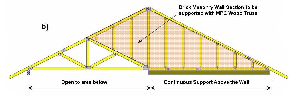
21 Background Examples of supporting brick veneer with MPCWT utilizing a steel lintel are given in the following examples (a) and (b)
22 Background
23 Background For buildings with conventional construction that contain structural elements exceeding the limits in IRC Section R301 Design Criteria or otherwise not conforming to this code, the IRC has provisions regarding designing these elements in accordance with accepted engineering practice R Engineered design
24 Background Furthermore, similar conceptual provision for structural components and/or assembly exceeding the limitation of conventional construction is addressed in Section of the 2012 International Building Code (IBC) Portions exceeding limitations of conventional light-frame construction
25 Analysis For the individual truss carrying the brick/masonry wall through a steel lintel attached to the truss, the guidance and recommendations on the following slides are provided based on our professional judgment and the following sources: 2015 IRC and 2015 IBC Wind loads specified in ASCE 7-10 Fastener strengths specified in the NDS Masonry Structures standards contained in TMS 402/602. General guidance given in Brick Industry Association s Technical Notes 18A, 28, 28B and 44B

26 Analysis The MPCWT must be designed for the additional loading from the brick where bearing is not directly below the brick If the angle iron is being supported by bolts attached directly to the MPCWT, then the MPCWT must be designed with the holes for the bolts taken into account.
27 Analysis Truss total load deflection is limited to L/600 Load Duration factor is C D =0.9 Creep factor for long-term deflection calculation shall be 1.5 for dry lumber and 2.0 for unseasoned lumber Creep is defined as time-dependent deformation of a structural member under constant load. In this case brick dead load is a constant and/or sustained load (see ANSI/TPI , 2007) Maximum weight of brick masonry veneer is 40 psf Maximum height of brick masonry is 12-8 per the IRC Sheathing must be covered with a water-resistant membrane, unless the sheathing is water resistant and the joints are sealed.
28 Analysis Steel lintel attachment to MPCWT should be per the following details:
29 Analysis
30 Analysis A minimum 6 x 4 x 5/16 (152 mm by 102 mm by 8 mm) steel angle, with the long leg placed vertically, shall be anchored to MPCWT using bolts per the following tables For assemblies with Structural Sheathing: Bolt Spacing (Truss Vertical Member Spacing) Bolt Diameter 1,b With Structural Sheathing (OSB, Plywood) 3/8-inch bolt diam. 1/2-inch bolt diam. 5/8-inch bolt diam. 3/4-inch bolt diam inches o.c. c Max inches o.c. c Max inches o.c. c Max. 9-4 Max. 6-1 Max. 9-5 Max Max. 7-9 Max Max a Max. 9-5 Max a Max a 1 Bolt shear capacity is calculated based on 2015 NDS for Wood Construction for lumber with Specific Gravity G=0.42 (Spruce-Pine-Fir) with moisture content less than 19% and the following adjustment factors: C D =0.9, C t and C M = Use only with minimum 2x4 vertical truss members. F em =4700 psi, F es =87000 psi, 5/16 Steel, no gap, Bolt F yb =45000 psi Brick weight up to 40 PSF. a The maximum height of brick masonry veneer above the steel angle support using prescriptive requirements of 2015 IRC shall be Weight of brick shall be included in truss design. b Pre-drill oval holes in the shelf angle for easier field installation adjustment. c It must be noted that the design of the truss only accounts for the gravitational loads in the plane of the truss. The building designer needs to adequately account for loads normal to the face of the truss and the bracing/restraint of the roof and wall system.
31 Analysis For assemblies with Non-Structural Sheathing: Bolt Spacing (Truss Vertical Member Spacing) Bolt Diameter 1,b With up to ½ of Non-Structural Sheathing (Weather Resistant Barrier, Insulation, etc.) 3/8-inch bolt diam. 1/2-inch bolt diam. 5/8-inch bolt diam. 3/4-inch bolt diam inches o.c. c Max. 3-1 Max. 4-4 Max. 5-6 Max inches o.c. c Max. 4-9 Max. 6-8 Max. 8-5 Max inches o.c. c Max. 6-6 Max. 9-0 Max Max a 1 Bolt shear capacity is calculated based on 2015 NDS for Wood Construction for lumber with Specific Gravity G=0.42 (Spruce-Pine-Fir) with moisture content less than 19% and the following adjustment factors: C D =0.9, C t and C M = Use only with minimum 2x4 vertical truss members. F em =4700 psi, F es =87000 psi, 5/16 Steel with ½ gap between steel and truss, Bolt F yb =45000 psi, Brick weight up to 40 PSF. a The maximum height of brick masonry veneer above the steel angle support using prescriptive requirements of 2015 IRC shall be Weight of brick shall be included in truss design. b Pre-drill oval holes in the shelf angle for easier field installation adjustment. c It must be noted that the design of the truss only accounts for the gravitational loads in the plane of the truss. The building designer needs to adequately account for loads normal to the face of the truss and the bracing/restraint of the roof and wall system.
32 Analysis An alternative connection using (3) 2x6 s to support the brick masonry veneer directly above the 2x6 s
33 Analysis Screw spacing and maximum details for the (3) 2x6 masonry support system are found in the following table: Fasten Master TLOK08/LOG008 or Simpson SDS25800 or USP WS8 Screws 1 8 minimum screw length SP/DFL SG=0.50 HF/SPF SG= Staggered Rows of 8 o.c. b,c Max a Max a 2 Staggered Rows of 12 o.c. b,c Max Max Staggered Rows of 16 o.c. b,c Max. 7-6 Max Staggered Rows of 24 o.c. b,c Max Max Screw shear capacity is calculated based on 2015 NDS for Wood Construction for lumber with Specific Gravity G=0.42 (Spruce-Pine-Fir) and Specific Gravity G=0.50 (Douglas Fir-Larch) with moisture content less than 19% and the following adjustment factors: C D =0.9, C t and C M = main member, 4-1/2 side member Use only with minimum 2x6 members. a The maximum height of brick masonry veneer above the steel angle support using prescriptive requirements of 2015 IRC shall be b Screws to be staggered half the oc spacing with a minimum 1-3/4 edge distance and 6 end distance. Weight of brick shall be included in truss design. c It must be noted that the design of the truss only accounts for the gravitational loads in the plane of the truss. The building designer needs to adequately account for loads normal to the face of the truss and the bracing/restraint of the roof and wall system.
 2x6 s to support the brick masonry")
34 Analysis Another alternative connection using (3) 2x6 s to support the brick masonry veneer:
35 Analysis An alternative connection using 2-ply MPCWT directly below to support the brick masonry veneer:

36 Analysis An alternative connection using 2x_ material between MPCWT to support the brick masonry veneer:
37 Analysis The maximum slope of the roof construction without stops welded to the steel angle shall be 7:12 Supporting the brick veneer with trusses with slopes from 7:12 up to 12:12 shall have stops, with a minimum size of 3 x3 x ¼ (76 mm x76 mm x 6 mm) steel plates, welded to the angle at a maximum spacing of 24 (610 mm) o.c. along the angle or as approved by the building official
38 Analysis Lateral support is provided by the ties and backing system. The ties must be capable of resisting tension and compression resulting from forces acting perpendicular to truss plane. Stainless steel ties specified under ASTM A 240 or A 580 Corrosion protected ties such as zinc coated corrugated steel ties, minimum 22 U.S. gauge thick ( ), 7/8 x 6 (0.76mm x 22 mm x 152 mm) complying with ASTM A 653 and A 153 class B2
 of brick veneer wall area For new construction, wall stud spacing of 16 o.c. is recommended so that ties can be anchored at this spacing")
39 Analysis Veneer ties shall be spaced at maximum 32 o.c. (610 mm) horizontally and 24 o.c. vertically and shall support max 2.67 ft 2 (0.25 m 2 ) of brick veneer wall area For new construction, wall stud spacing of 16 o.c. is recommended so that ties can be anchored at this spacing

40 Analysis Strand wire ties are less susceptible to corrosion than corrugated steel sheet ties Minimum strand wire size diameter shall be 9 U.S. gauge [(0.148 ) or (4 mm)] and be spaced same as corrugated steel ties and shall have a hook embedded in the mortar joint
41 Analysis The following tables provide recommendations for maximum vertical tie spacing for high wind areas when structural gable truss vertical members are spaced at 24, 16 and 12 on center spacing In the areas that are susceptible to both high wind and seismic loads, masonry brick veneer system should be evaluated by an RDP to ensure that brick veneer cladding can resist both seismic and wind design loads
42 Analysis Maximum vertical tie spacing for assemblies with structural sheathing Maximum Vertical spacing for Ties in inches 1,2,3,4,8 8d (0.131 x 2.5 ) Ring-Shank Nails Wind Speed Wind 1,2,9 With ½ Structural Sheathing (OSB, or Plywood) and 2 of Nail penetration 4 (3-sec Peak Gust) Pressure (psf) Truss 24 o.c. Truss 16 o.c. Truss 12 o.c. SPF SYP SPF SYP SPF SYP 115 mph mph mph mph mph mph mph 46.8 NA 7 NA , The vertical tie spacing is based on wind loads derived from ASCE 7-10 Components and Cladding Method 1 (simplified Figure , Zone 5, Effective wind area = 10 sf), located in Exposure category B, h = 30 ft., importance factor (I=1) and no topographic influence (K zt =1.0). For other heights, exposure, importance factor and topographic influence, an engineered design is recommended. Table based on a tie in every vertical. 2 Net Design Wind Pressures from ASCE 7-10 Figure have been multiplied by 0.6 for Allowable Stress Design. 3 Nail withdrawal strength is for truss lumber with Specific Gravity G=0.42 (Spruce-Pine-Fir (SPF)) and G=0.55 (Southern Yellow Pine (SYP)) with moisture content less than 19% and the following adjustment factors: C D =1.0, C t= 0.8, C M, C eg, and C tn =1.0. See FEMA Technical Fact Sheet No. 5.4 Attachment of Brick Veneer in High- Wind Regions. W = 1800G 2 D x 1.6 SPF NV = SYP NV = Nail embedment depth of 2 was assumed for 8d common ring-shank nails ( diameter x 2 ½ -long) (1-1/2 truss plus ½ structural sheathing). A minimum of 3 (0.131 x 2 ) nails required attaching the sheathing to the truss for every tie. 5 The maximum vertical spacing allowed by the Brick Industry Association s Technical Notes 28 is 24 & requires an anchor for every 2.67 sq. ft. of wall area. 6 Where the wind pressure exceeds 30 psf, reduce wall area supported by each anchor to max. 2 SF per the IRC R & the Brick Industry Association s Technical Note 28 7 Where wind pressure exceeds 40 psf do not space anchors more than 18 vertically & horizontally per the Brick Industry Association s Technical Note 28 8 Additional anchors required around openings larger than 16 in either dimension. See the IRC or IBC for these requirements. 9 It must be noted that the design of the truss only accounts for the gravitational loads in the plane of the truss. The building designer needs to adequately account for loads normal to the face of the truss and the bracing/restraint of the roof and wall system.
43 Analysis Maximum vertical tie spacing for assemblies with non-structural sheathing Maximum Vertical spacing for Ties in inches 1,2,3,4,8 8d (0.131 x 2.5 ) Ring-Shank Nails Wind Speed Wind 1,2,9 With Non-Structural Sheathing (Weather Resistant Barrier, Insulation, etc.) and 1-1/2 of Nail penetration in truss member. (3-sec Peak Gust) Pressure (psf) Truss 24 o.c. Truss 16 o.c. Truss 12 o.c. SPF SYP SPF SYP SPF SYP 115 mph mph mph mph mph mph mph 46.8 NA 7 NA The vertical tie spacing is based on wind loads derived from ASCE 7-10 Components and Cladding Method 1 (simplified Figure , Zone 5, Effective wind area = 10 sf), located in Exposure category B, h = 30 ft., importance factor (I=1) and no topographic influence (K zt =1.0). For other heights, exposure, importance factor and topographic influence, an engineered design is recommended. Table based on a tie in every vertical. 2 Net Design Wind Pressures from ASCE 7-10 Figure have been multiplied by 0.6 for Allowable Stress Design. 3 Nail withdrawal strength is for truss lumber with Specific Gravity G=0.42 (Spruce-Pine-Fir (SPF)) and G=0.55 (Southern Yellow Pine (SYP)) with moisture content less than 19% and the following adjustment factors: C D =1.0, C t= 0.8, C M, C eg, and C tn =1.0. See FEMA Technical Fact Sheet No. 5.4 Attachment of Brick Veneer in High- Wind Regions. W = 1800G 2 D x 1.6 SPF NV = 49.9 SYP NV = Nail embedment depth of 1-1/2 was assumed for 8d common ring-shank nails ( diameter x 2 ½ -long). 5 The maximum vertical spacing allowed by the Brick Industry Association s Technical Notes 28 is 24 & requires an anchor for every 2.67 sq. ft. of wall area. 6 Where the wind pressure exceeds 30 psf, reduce wall area supported by each anchor to max. 2 SF per the IRC R & the Brick Industry Association s Technical Note 28 7 Where wind pressure exceeds 40 psf do not space anchors more than 18 vertically & horizontally per the Brick Industry Association s Technical Note 28 8 Additional anchors required around openings larger than 16 in either dimension. See the IRC or IBC for these requirements. 9 It must be noted that the design of the truss only accounts for the gravitational loads in the plane of the truss. The building designer needs to adequately account for loads normal to the face of the truss and the bracing/restraint of the roof and wall system.
44 Analysis Flashing and weep holes shall be located in the brick veneer wythe above the steel angle per the building codes. Flashing should consist of normal base flashing, step flashing and counter flashing installed directly on the adjacent (i.e., lower) roof sheathing. Weep holes shall be at a maximum spacing of 33 (838 mm) o.c. and shall be not less than 3/16 (5 mm) in diameter.
 o.c.")
45 Analysis Create vertical expansion a maximum 25 (7.6 m) o.c.
 and")
46 Analysis The actual location of vertical expansion joints in a structure depends on the structural configuration as well as the expected amount of horizontal movement Expansion joints are typically sized similar to a mortar joint, usually between 3/8 (10 mm) and ½ (13 mm)

47 Analysis Vertical expansion joints should also be considered with: Corners Offsets Setbacks Wall intersections Changes in the wall height Wall backing system changes Brick veneer support changes Wall function or climatic exposure changes

48 Analysis MPCWT may also be used to support brick veneer at dormer locations. Depending on where the dormer is placed, the truss may need to be designed with an additional point load from a header carrying the front of the dormer brick veneer loading.
49 Conditions of Use Metal plate connected wood trusses can effectively support brick masonry veneer when properly designed to do so. Code compliant use of MPCWT to support brick veneer may be accomplished by both individual designs and by adhering to the recommendations shown here. The concepts shown can be applied to many different situations utilizing MPCWT s and are presented only as a guide for use by a qualified Building Designer and/or Contractor.
50 References American Forest & Paper Association (AF&PA) National Design Specification (NDS ) for Wood Construction. AF&PA, th Street, NW, Suite 800, Washington, DC American Concrete Institute, Masonry Standard Joint Committee (MSJC), Building Code requirements for Masonry Structures (ACI /ASCE 5-11/TMS ) and Specifications for Masonry Structures (ACI /ASCE 6-11/TMS ). IRC. International Residential Code (2015 edition). International Code Council, Inc., Washington, DC. IBC. International Building Code (2015 edition). International Code Council, Inc., Washington, DC. ASCE, Minimum Design Loads for Buildings and Other Structures (ASCE 7-10), American Society of Civil Engineers, Reston, VA. Masonry Advisory Council. Supporting Exterior Brick Veneer on Wood Construction The Brick Industry Association. Technical Notes on Brick Construction 18A, 28, 28A and 44B.
Exterior Brick Masonry Veneer Supported by Metal Plate Connected Wood Trusses (MPCWT) Design Guide Revised 11/17/2016
 Design Guide Revised 11/17/2016") Exterior Brick Masonry Veneer Supported by Metal Plate Connected Wood Trusses (MPCWT) Design Guide Revised 11/17/2016 SBCA has been the voice of the structural building components industry since 1983,
Exterior Brick Masonry Veneer Supported by Metal Plate Connected Wood Trusses (MPCWT) Design Guide Revised 11/17/2016 SBCA has been the voice of the structural building components industry since 1983,
Exterior Brick Masonry Veneer Supported by Metal Plate Connected Wood Trusses. DD No
 Exterior Brick Masonry Veneer Supported by Metal Plate Connected Wood Trusses. DD No. 1608-01 Structural Building Components Association (SBCA) Issue Date: August 8, 2016 6300 Enterprise Lane Madison,
Details for Exterior Brick Masonry Veneer Supported by Metal Plate Connected Wood Trusses
 Details for Exterior Brick Masonry Veneer Supported by Metal Plate Connected Wood Trusses Released May 20, 2009 Updated March 9, 2011 Introduction: Wood frame structures with attached brick masonry veneer
Stone and Masonry Veneer
 Stone and Masonry Veneer R703.7 Stone and masonry veneer, general. Stone and masonry veneer shall be installed in accordance with this chapter, Table R703.4 and Figure R703.7. These veneers installed over
Strong-Drive SDWS TIMBER Screw
 Simpson Strong-Tie Fastening Systems Structural Wood-to-Wood Connections including Ledgers Designed to provide an easy-to-install, high-strength alternative to through-bolting and traditional lag screws.
Carroll County Bureau of Permits and Inspection Residential Code Compliance Guidelines Detached Garage
 Carroll County Bureau of Permits and Inspection Residential Code Compliance Guidelines Detached Garage The following list of code requirements is intended to assist you in complying with the Code of Public
Table 3. Detailed Comparison of Structural Provisions of IRC 2000 and 1997 NEHRP (Continued)
") 2000 IRC 1997 NEHRP Section Provision Section Provision Comments CHAPTER 3 BUILDING PLANNING R301 DESIGN CRITERIA R301.2.2 Seismic Provisions R301.2.2.1 Determination of Seismic Design Category R301.2.2.1.1
2000 IRC 1997 NEHRP Section Provision Section Provision Comments CHAPTER 3 BUILDING PLANNING R301 DESIGN CRITERIA R301.2.2 Seismic Provisions R301.2.2.1 Determination of Seismic Design Category R301.2.2.1.1
Masonry Veneer - Chapter 6. Masonry Veneer Anchored Veneer
 Masonry Veneer - Chapter 6 Chapter 6 covers anchored and adhered veneer. Following are prescriptive requirements for areas with wind 110 mph Vertical support of masonry veneer Support: Noncombustible structural
Attachment of Residential Deck Ledger to Metal Plate Connected Wood Truss Floor Systems
 to Metal Plate Connected Wood Truss Floor Systems Structural Building Components Association (SBCA) February 17, 2015 Revised August 15, 2017 SBCA is an APPROVED SOURCE This research report is based on
Guide to Attaching Exterior Wall Coverings through Foam Sheathing to Wood or Steel Wall Framing
 Guide to Attaching Exterior Wall Coverings through Foam Sheathing to Wood or Wall Framing Released September 20, 2010 Updated December 4, 2012 Note: Tables for cladding attachments to wood framing have
CONCRETE MASONRY VENEERS TEK 3-6C
 An information series from the national authority on concrete masonry technology CONCRETE MASONRY VENEERS TEK 3-6C Construction (2012) INTRODUCTION In addition to its structural use or as the exterior
INTERNATIONAL ASSOCIATION OF PLUMBING AND MECHANICAL OFFICIALS UNIFORM EVALUATION SERVICES
 INTERNATIONAL ASSOCIATION OF PLUMBING AND MECHANICAL OFFICIALS UNIFORM EVALUATION SERVICES EVALUATION CRITERIA FOR ANCHORED MASONRY VENEER SYSTEM WITH POLYSTYRENE FOAM PLASTIC BACKING EC 021-2014 (Adopted
SECTION R614 STRUCTURAL INSULATED PANEL WALL CONSTRUCTION
 Section R614 Add new section to read as shown: (RB34-06/07) SECTION R614 STRUCTURAL INSULATED PANEL WALL CONSTRUCTION R614.1 General. Structural insulated panel (SIP) walls shall be designed in accordance
Attachment A. USG Minimum Design and Construction Requirements for Wood Framed Structures
 Attachment A USG Minimum Design and Construction Requirements for Wood Framed Structures 1. General Design Criteria 1.1. Per Adopted Georgia State Minimum Standard Building Code 1.2. Minimum Live Loads
Brick Masonry. Best Practices Guide
 Brick Masonry Best Practices Guide 1. Brick 2. Brick Blending 3. Wall Ties 4. Flashing 5. Steel Lintels 6. Weep Holes 7. General Recommendations Content The information and suggestions contained in this
CONNECTOR S T U D S H E A R. Design for Composite Structural Action STUD SHEAR CONNECTOR APPLICATION
 S T U D S H E A R CONNECTOR STUD SHEAR CONNECTOR APPLICATION Design for Composite Structural Action Exterior ashlar-type masonry veneer, typically of clay brick or concrete block masonry, are commonly
PRODUCT: Structural Insulated Panels (SIPs) DIVISION: Wood, Plastics, and Composites (06) SECTION: Structural Panels ( )
 DIVISION: Wood, Plastics, and Composites (06) SECTION: Structural Panels ( )") PRODUCT: Structural Insulated Panels (SIPs) DIVISION: Wood, Plastics, and Composites (06) SECTION: Structural Panels (06 12 00) Report Holder ACME Panel Company 1905 West Main St. Radford, VA 24141 Manufacturing
PRODUCT: Structural Insulated Panels (SIPs) DIVISION: Wood, Plastics, and Composites (06) SECTION: Structural Panels (06 12 00) Report Holder ACME Panel Company 1905 West Main St. Radford, VA 24141 Manufacturing
LP OSB Sheathing & Structural 1 Sheathing
 Rated OSB Sheathing Roof Panels Span Ratings Max. Live Load Thickness Span Rating for Roofs (lbs)** 3/8" 24/0 30 7/16" 24/16 40 15/32" 32/16 70 1/2" 32/16 70 19/32" 40/20 130 23/32" 48/24 175 1-1/8" 48
ESR-2894 Reissued April 2014 This report is subject to renewal April 1, 2016.
 ICC-ES Evaluation Report ESR-894 Reissued April 04 This report is subject to renewal April, 0. www.icc-es.org (800) 4-87 () 99-04 A Subsidiary of the International Code Council DIVISION: 07 00 00 THERMAL
Anchor bolts ASTM F1554, Gr. 36 Wide flange beams ASTM A992, Fy = 50 ksi Misc. structural steel ASTM A36, Fy = 36 ksi
 STRUCTURAL NOTES MATERIAL STRENGTHS Structural Steel Reinforcing Steel Concrete Masonry Structural Lumber Anchor bolts ASTM F1554, Gr. 36 Wide flange beams ASTM A992, Fy = 50 ksi Misc. structural steel
Supplemental Plan Correction Sheet for LA Residential Code Prescriptive Design (2014 LARC)
") Supplemental Plan Correction Sheet for LA Residential Code Prescriptive Design (2014 LARC) Plan Check Submittal Date: Plan Check #: Permit App.# Job Address: Applicant: Phone: ( ) Plan Check Engineer:
Supplemental Plan Correction Sheet for LA Residential Code Prescriptive Design (2014 LARC) Plan Check Submittal Date: Plan Check #: Permit App.# Job Address: Applicant: Phone: ( ) Plan Check Engineer:
Murphy LVL Limit States Design Guide 2.0 E-LVL 2.2 E-LVL
 Murphy LVL Limit States Design Guide 2.0 E-LVL 2.2 E-LVL Our Company At Murphy Company we take pride in providing our customers with premium quality products and services. Our LVL is manufactured to provide
APPENDIX A1 WIND AND SEISMIC BRACING GUIDELINE FOR ONE AND TWO FAMILY DWELLINGS AND TOWNHOUSES
 ST. LOUIS COUNTY DEPARTMENT OF PUBLIC WORKS DIVISION OF CODE ENFORCEMENT APPENDIX A1 WIND AND SEISMIC BRACING GUIDELINE FOR ONE AND TWO FAMILY DWELLINGS AND TOWNHOUSES Lateral Loads All buildings are subject
Supplemental Plan Correction Sheet for LA Residential Code Prescriptive Design (2011 LARC)
") Supplemental Plan Correction Sheet for LA Residential Code Prescriptive Design (2011 LARC) Plan Check Submittal Date: Plan Check #: Permit App.# Job Address: Applicant: Phone: ( ) P.C. Engineer: Phone:
Supplemental Plan Correction Sheet for LA Residential Code Prescriptive Design (2011 LARC) Plan Check Submittal Date: Plan Check #: Permit App.# Job Address: Applicant: Phone: ( ) P.C. Engineer: Phone:
PRODUCT: Structural Insulated Panels (SIPs) DIVISION: Wood and Plastics (06) SECTION: Structural Panels ( )
 DIVISION: Wood and Plastics (06) SECTION: Structural Panels ( )") PRODUCT: Structural Insulated Panels (SIPs) DIVISION: Wood and Plastics (06) SECTION: Structural Panels (06 12 16) Report Holder Thermocore Panel Systems, Inc. 1801 Hancel Parkway Mooresville, Indiana
PRODUCT: Structural Insulated Panels (SIPs) DIVISION: Wood and Plastics (06) SECTION: Structural Panels (06 12 16) Report Holder Thermocore Panel Systems, Inc. 1801 Hancel Parkway Mooresville, Indiana
Load Design Charts. R-CONTROL SIPs STRUCTURAL INSULATED PANELS. CONTROL, NOT COMPROMISE.
 R-CONTROL s STRUCTURAL INSULATED PANELS Note: Information deemed reliable at time of printing. Please visit www.r-control.com for latest information. June 2012 CONTROL, NOT COMPROMISE. www.r-control.com
PRODUCT: Structural Insulated Panels (SIP) DIVISION: Wood and Plastics (06) SECTION: Structural Panels ( )
 DIVISION: Wood and Plastics (06) SECTION: Structural Panels ( )") PRODUCT: Structural Insulated Panels (SIP) DIVISION: Wood and Plastics (06) SECTION: Structural Panels (06 12 16) Report Holder General Panel Corporation PO Box 279 2604 Sunset Drive Grenada, Mississippi
PRODUCT: Structural Insulated Panels (SIP) DIVISION: Wood and Plastics (06) SECTION: Structural Panels (06 12 16) Report Holder General Panel Corporation PO Box 279 2604 Sunset Drive Grenada, Mississippi
Featuring Selection and Installation Information for Lateral Wind Loads
 #TJ-8000 SPECIFIER S GUIDE 1¼" TIMBERSTRAND LSL RIM BOARD AND 1 1 8" TJ RIM BOARD Featuring Selection and Installation Information for Lateral Wind Loads For Use in ASCE/SEI 7-05 Basic Wind Speed Regions
INSULATION RETROFIT DESIGN ENERGY SOLUTIONS CENTRE YUKON GOVERNMENT
 INSULATION RETROFIT DESIGN ENERGY SOLUTIONS CENTRE YUKON GOVERNMENT MAY 2009 prepared by N. A. JACOBSEN, P.Eng. CIVIL ENGINEERING CONSULTANT Whitehorse, Yukon ENERGY SOLUTIONS CENTRE YUKON GOVERNMENT MAY
Listing Report: MUR Reissue Date: 12/07/17 This report is subject to annual review
 CSI 06 12 16 PRODUCT: Structural Insulated Panels (SIPs) DIVISION: Wood and Plastics SECTION: Structural Panels Report Holder The Murus Company PO Box 220 Mansfield, PA 16933 Manufacturing Locations The
REPORT HOLDER: FASTENING SPECIALISTS, INC. 726 CENTRAL FLORIDA PARKWAY ORLANDO, FLORIDA EVALUATION SUBJECT:
 0 Most Widely Accepted and Trusted ICC ES Evaluation Report ICC ES 000 (800) 423 6587 (562) 699 0543 www.icc es.org ESR 2328 Reissued 10/2017 This report is subject to renewal 10/2018. DIVISION: 03 00
Joint Evaluation Report
 0 Joint Evaluation Report ICC-ES (800) 423-6587 (562) 699-0543 www.icc-es.org 000 ESR-1040 Reissued 09/2016 This report is subject to renewal 09/2018. DIVISION: 06 00 00 WOOD, PLASTICS AND COMPOSITES SECTION:
Joint Evaluation Report
 0 Joint Evaluation Report ICC-ES (800) 423-6587 (562) 699-0543 www.icc-es.org 000 ESR-1040 Reissued 09/2018 This report is subject to renewal 09/2019. DIVISION: 06 00 00 WOOD, PLASTICS AND COMPOSITES SECTION:
Product Guide Specification
 Norplex-Micarta October 2007 665 Lybrand Street Postville, Iowa 52162 Toll Free (800) 568-8108 Phone (817) 329-6191 Fax (817) 421-4208 Website www.stormblocker.com E-mail support@stormblocker.com Product
ANALYTICAL MODELING OF IN PLANE SHEAR OF BRICK VENEER AND WOOD STUD WALLS
 10 th Canadian Masonry Symposium, Banff, Alberta, June 8 12, 2005 ANALYTICAL MODELING OF IN PLANE SHEAR OF BRICK VENEER AND WOOD STUD WALLS Eric N. Johnson 1 and W. Mark McGinley 2 1 Director of Engineering,
ACCESSORY STRUCTURE Building permit information For 1 & 2-family dwellings
 ACCESSORY STRUCTURE Building permit information For 1 & 2-family dwellings Building Safety Department 400-2 nd Street South St. Cloud, MN 56301 (320) 255-7239 A building permit is required for any accessory
HILLSBOROUGH TOWNSHIP CODE ENFORCEMENT
 HILLSBOROUGH TOWNSHIP CODE ENFORCEMENT SAMPLE GUIDE FOR RESIDENTIAL DECKS revised 7 16 Call before you dig! 1 800 272 1000 New Jersey One Call. Utility Mark Out. THIS GENERIC GUIDE IS NOT ALL INCLUSIVE
FIRE RESISTANCE TESTS OF BRICK VENEER / WOOD FRAME WALLS J. GREGG BORCHELT
 FIRE RESISTANCE TESTS OF BRICK VENEER / WOOD FRAME WALLS J. GREGG BORCHELT Vice President Engineering and Research Brick Industry Association Reston, VA United States of America JOHN SWINK Regional Engineer
Earthquake Resistant Residential Design and Construction, Part 2
 Earthquake Resistant Residential Design and Construction, Part 2 Course No: S05-007 Credit: 5 PDH John L. Galinski, PE Continuing Education and Development, Inc. 9 Greyridge Farm Court Stony Point, NY
DECK PERMIT APPLICATION
 DECK PERMIT APPLICATION APPLICANT S INFORMATION Name: Company Name: Current address: City: State: ZIP Code: Phone: Email: PROPERTY OWNER S INFORMATION Name: Property Address: Phone: E-mail: City: State:
HOLDOWN & STRAP SCHEDULE
 SHEAR WALL SCHEDULE STRUCTURAL DESIGN CRITERIA GOVERNING CODE SOIL BEARING PRESSURE HOLDOWN & STRAP SCHEDULE MARK SHEATHING SHEATH BOTH SIDES NAILS EDGE SPACING NOTES MARK SW 7/" OSB NO 8d " OC - A SW
DIVISION: THERMAL AND MOISTURE PROTECTION SECTION: SIDING REPORT HOLDER: SHAKERTOWN 1992, INC.
 0 Most Widely Accepted and Trusted ICC ES Report ICC ES 000 (800) 423 6587 (562) 699 0543 www.icc es.org ESR 2386 Reissued 04/2016 This report is subject to renewal 04/2018. DIVISION: 07 00 00 THERMAL
Typical Deck Details Based on the 2009 International Residential Code (Designed and Printed August 2010)
") 1307 West Lehigh Street Bethlehem, PA 18018 610-866-9663 Office info@keycodes.net www.keycodes.net Typical Deck Details Based on the 2009 International Residential Code (Designed and Printed August 2010)
1307 West Lehigh Street Bethlehem, PA 18018 610-866-9663 Office info@keycodes.net www.keycodes.net Typical Deck Details Based on the 2009 International Residential Code (Designed and Printed August 2010)
STRUCTURAL CALCULATIONS EXTERIOR SIDING CLADDING SYSTEM FLUSH PANEL SIDING SYSTEM AND LAPPED PANEL SIDING SYSTEM
 JN 3617 Page 1 of 27 NOTES ON ANALYSIS, DESIGN METHOD, BUILDING CODE REFERENCES, AND ASSUMPTIONS. The exterior phenolic panel siding system is classified under the International Building Code as a Non-
CHAPTER 3 BUILDINGS WITH WOOD FRAMED EXTERIOR WALLS 301 SCOPE
 CHAPTER 3 BUILDINGS WITH WOOD FRAMED EXTERIOR WALLS WOOD CHAPTER 3 301 SCOPE This chapter prescribes construction requirements for buildings where all exterior walls above the foundation are wood framed
CONTINUING EDUCATION CREDITS
 CONTINUING EDUCATION CREDITS All participants will automatically receive a certificate of completion via email. Please allow 2-3 weeks for your certificate to be processed. AIA/CES CEHs will be submitted
IAPMO UNIFORM EVALUATION SERVICES EVALUATION CRITERIA FOR JOIST HANGERS AND MISCELLANEOUS CONNECTORS
 IAPMO UNIFORM EVALUATION SERVICES EVALUATION CRITERIA FOR JOIST HANGERS AND MISCELLANEOUS CONNECTORS EC 002-2017 (Adopted June 2007, Revised August 2017) 1.0 INTRODUCTION 1.1 Purpose: The purpose of this
SUBJECT: NEW 2000 INTERNATIONAL RESIDENTIAL CODE (IRC) DATE:
 DATE:") IRC CODE UPDATES TO: RESIDENTIAL BUILDING CONTRACTORS FROM: GARY STABER, BUILDING OFFICIAL SUBJECT: NEW 2000 INTERNATIONAL RESIDENTIAL CODE (IRC) DATE: 6/1/2003 INTERNATIONAL RESIDENTIAL CODE (IRC) APPLICABILITY:
IRC CODE UPDATES TO: RESIDENTIAL BUILDING CONTRACTORS FROM: GARY STABER, BUILDING OFFICIAL SUBJECT: NEW 2000 INTERNATIONAL RESIDENTIAL CODE (IRC) DATE: 6/1/2003 INTERNATIONAL RESIDENTIAL CODE (IRC) APPLICABILITY:
Residential Deck Safety, Construction and Repair. Juneau Permit Center, 4 th Floor Marine View Center,(907) February 2016
 February 2016") February 2016 Residential Deck Safety, Construction and Repair Juneau Permit Center, 4 th Floor Marine View Center,(907)586-0770 This handout is designed to help you build your deck to comply with the
February 2016 Residential Deck Safety, Construction and Repair Juneau Permit Center, 4 th Floor Marine View Center,(907)586-0770 This handout is designed to help you build your deck to comply with the
TER No Cultured Stone & ProStone Applications Over Continuous Insulation
 Cultured Stone & ProStone Applications Over Continuous Insulation TER No. 1302-01 Boral Stone Products LLC 200 Mansell Court East, Suite 310 Roswell, GA 30076 419-318-5345 949-341-8890 (fax) chris.hines@boral.com
FACT SHEET #2 DECK INFORMATION
 Borough of Doylestown Building and Zoning Department 57 West Court Street, Doylestown, PA 18901 215.345.4140 FACT SHEET #2 DECK INFORMATION BACKGROUND The provisions of the PAUCC. ICC Property Maintenance
Joint Evaluation Report ICC-ES (800) (562)
 (562)") 0 Joint Evaluation Report ICC-ES (800) -658 (56) 699-05 www.icc-es.org 000 ESR-0 Reissued 0/0 This report is subject to renewal 0/08. DIVISION: 06 00 00 WOOD, PLASTICS AND COMPOSITES SECTION: 06 6 00 SHEATHING
0 Joint Evaluation Report ICC-ES (800) -658 (56) 699-05 www.icc-es.org 000 ESR-0 Reissued 0/0 This report is subject to renewal 0/08. DIVISION: 06 00 00 WOOD, PLASTICS AND COMPOSITES SECTION: 06 6 00 SHEATHING
Garage/Accessory Structures
 Garage/Accessory Structures City of New Prague Building Inspections Department 118 Central Ave N New Prague, MN 56071 (952) 758-4401 Fax (952) 758-1149 Requirements for submitted Building Plans Signed
Typical Deck. CONSTRUCTION TIP SHEET 5 Basic Decks w/ 60 psf Live Loading
 CONSTRUCTION TIP SHEET 5 Basic Decks w/ 60 psf Live Loading April 1, 2017 This Tip Sheet reflects code requirements of the 2015 International Residential Code (IRC) with Washington State Amendments which
Building Division Informational Handout
 CITY OF SAN JOSÉ, CALIFORNIA Building Division Informational Handout Conventional Light Frame Construction Design Provisions 2007 CBC Handout No. 2-21 Published: 1/1/08 Page 1 of 3 This document summarizes
Specifications. Materials and Fabrication. Physical Properties. Environmental Impact. Sizes. Installation - General Requirements.
 Specifications Materials and Fabrication Physical Properties LP FlameBlock Fire-Rated OSB Sheathing panels are made of oriented strand board (OSB) with a fire-resistant, cementitious coating (Pyrotite
GARAGE MAIN FLOOR PLAN
 BUILDING CONTRACTOR/HOME OWNER TO REVIEW AND VERIFY ALL DIMENSIONS, SPECS, AND CONNECTIONS BEFORE CONSTRUCTION BEGINS. SHED TO BE BUILT AS PER IRC, UBC OR CURRENT LOCAL CODE To the best of my knowledge
Table of Contents 2. Structural Systems.4 Foundations.4 Floor System...4 Columns..5 Lateral System...5
 WISCONSIN PLACE RESIDENTIAL TECHNICAL ASSIGNMENT 1 OCTOBER 5, 2007 KURT KRASAVAGE THE PENNSYLVANIA STATE UNIVERSITY STRUCTURAL OPTION FACULTY ADVISOR: DR. ALI MEMARI Table of Contents Table of Contents
HIGH PERFORMANCE FIRE RETARDANT TREATED WOOD PRODUCTS
 TM HIGH PERFORMANCE FIRE RETARDANT TREATED WOOD PRODUCTS Innovators of high performance fire retardant products Class A Rated Fire Retardant Treated Wood Products TM Certified and Listed with Accredited
Heel Blocking Requirements and Capacity Analysis. Overview Revised 3/22/2017
 Heel Blocking Requirements and Capacity Analysis Overview Revised 3/22/2017 SBCA has been the voice of the structural building components industry since 1983, providing educational programs and technical
DIVISION: WOOD, PLASTICS AND COMPOSITES SECTION: NAILS REPORT HOLDER: HY-TEK FASTENERS INC. EVALUATION SUBJECT: HY-TEK NAILS
 0 ICC-ES Evaluation Report ICC-ES 000 (800) 423-6587 (562) 699-0543 www.icc-es.org Most Widely Accepted and Trusted ESR-2648 Reissued 06/2018 Revised 10/24/2018 This report is subject to renewal 06/2020.
Typical Deck. CONSTRUCTION TIP SHEET 5 Basic Decks w/ 60 lb Live Loading
 CONSTRUCTION TIP SHEET 5 w/ 60 lb Live Loading April 1, 2017 This Tip Sheet reflects code requirements of the 2015 International Residential Code (IRC) with Washington State Amendments which update the
Joint Evaluation Report
 0 Joint Evaluation Report ICC ES (800) 423 6587 (562) 699 0543 www.icc es.org 000 ESR 1040 Reissued 09/2018 Revised 03/2019 This report is subject to renewal 09/2019. DIVISION: 06 00 00 WOOD, PLASTICS
POST FRAME BUILDING STANDARDS
 CASS COUNTY, MISSOURI BUILDING CODES, ENVIRONMENTAL HEALTH AND ZONING DEPARTMENT 30508 S. West Outer Road, Harrisonville, MO 64701 P- (816) 380-8134 F- (816) 380-8130 POST FRAME BUILDING STANDARDS 201.3
MASONRY ANCHORS AND CONNECTORS May 6, 2014
 Page - 1 This section includes specification text to assist in describing a variety of masonry anchors, connectors, and accessories intended for masonry construction. This document contains prepared master
Versetta Stone Panelized Stone Veneer Applications Over Continuous Insulation. TER No Boral Stone Products LLC
 Applications Over Continuous Insulation TER No. 1212-01 Boral Stone Products LLC 200 Mansell Court East, Suite 310 Roswell, GA 30076 419-318-5345 949-341-8890 (fax) chris.hines@boral.com versettastone.com
1¾" VERSA-LAM WESTERN HEAdER GuidE
 1¾" VERSA-LAM 1.7 2400 WESTERN HEAdER GuidE for products manufactured in White City, Oregon 11/29/2012 1¾" 1.7 2400 VL Guide 2 VERSA-LAM Products 1¾" VERSA-LAM 1.7 2400 An Introduction to VERSA-LAM Products
GARAGES/ONE-STORY City of Grand Rapids Building Safety Division
 GARAGES/ONE-STORY City of Grand Rapids Building Safety Division 218-326-7601 www.cityofgrandrapidsmn.com This handout is intended only as a guide and is based in part on the 2015 Minnesota State Building
WALL CONSTRUCTION CHAPTER 6
 CHAPTER 6 WALL CONSTRUCTION SECTION R601 GENERAL R601.1 Application. The provisions of this chapter shall control the design and construction of all walls and partitions for all buildings. R601.2 Requirements.
Technical Data Sheet
 Technical Data Sheet ProGUARD Concrete Insulated Sheathing Specifications & Installation Table Of Contents Product Description... pg. 1 Basic Use... pg. 1 Exterior Finishes... pg. 1 Standard Sizes... pg.
CONNECTOR B L O C K S H E A R. Design for Composite Structural Action BLOCK SHEAR CONNECTOR APPLICATION. Airspace
 B L O C K S H E A R CONNECTOR BLOCK SHEAR CONNECTOR APPLICATION Airspace Design for Composite Structural Action Exterior ashlar-type masonry veneer, typically of clay brick or concrete block masonry, are
Framing Methods Structural Components
 Framing Methods Structural Components Balloon Framing *Balloon framing or Eastern framing the exterior studs run from the top of the foundation to the top of the highest level. Benefits of this type of
OUR COMPANY OUR WARRANTY OUR GUARANTEE
 DESIGN MANUAL-USA FRAMED BY QUALITY BUILT WITH SUCCESS OUR COMPANY At International Beams Inc. we take pride in providing our customers with premium quality products and services. Our full range of engineered
ICC ES SYSTEM SYSTEM. Trusted DIVISION: 07 SECTION: AND FINISH REPORT HOLDER: ICC-ES Evaluation. Reissued 08/2016.
 0 Most Widely Accepted and Trusted ICC ES Evaluation Report ICC ES 000 (800) 423 6587 (562) 699 0543 www.icc es.orgg ESR 2562 Reissued 08/206 This report is subject to renewal 08/208. DIVISION: 07 00 00
TER No Use of FastenMaster HeadLOK Fasteners to Attach Cladding and/or Furring to Wood Framing through Foam Sheathing
 Use of FastenMaster HeadLOK Fasteners to through Foam Sheathing OMG, Inc. d/b/a/ FastenMaster 153 Bowles Road Agawam, Massachusetts, 01001 413-789-0252 fastenmaster.com mguthrie@olyfast.com TER No. 1009-01
HUMBOLDT COUNTY BUILDING & SAFETY DEPARTMENT CITY OF WINNEMUCCA BUILDING DEPARTMENT
 HUMBOLDT COUNTY BUILDING & SAFETY DEPARTMENT CITY OF WINNEMUCCA BUILDING DEPARTMENT FOR PRIVATE THREE-SIDED POST FRAMED (NON-ENGINEERED) OUTBUILDINGS LOCATED ON RESIDENTIAL LOTS ONLY Buildings must meet
Impact of C&C loads due to ASCE/SEI Overview Revised 3/23/2017
 Impact of C&C loads due to ASCE/SEI 7-16 Overview Revised 3/23/2017 SBCA has been the voice of the structural building components industry since 1983, providing educational programs and technical information,
Structural Criteria for Residential Rooftop Solar Energy Installations
 Structural Criteria for Residential Rooftop Solar Energy Installations STEP 3 Expedited Structural Criteria Use of this document This toolkit document includes a list of structural criteria for over-the-counter
LPI 56 Technical Guide
 LPI 56 Technical Guide Floor & Roof Applications Product Specifications & Design Values 2 Floor Tables 3 Uniform Floor Load (PLF) Tables: Simple s 4 Uniform Floor Load (PLF) Tables: Continuous s 5 Uniform
Wall bracing panel requirements
 Wall bracing panel requirements Building Inspections Exterior and interior walls must be braced in accordance with Minnesota State Building Code section R602 to resist wind loads and racking. Locations,
NOVABRIK MORTARLESS CONCRETE BRICK VENEER SPECIFICATION. MASTERFORMAT SECTION (Mortarless Concrete Brick Veneer)
") NOVABRIK MORTARLESS CONCRETE BRICK VENEER SPECIFICATION MASTERFORMAT SECTION 04818 (Mortarless Concrete Brick Veneer) Spec_USA_En_18102005.doc 12/1/2005 Novabrik Page 2 Section 04818 NOVABRIK MORTARLESS
NOVABRIK MORTARLESS CONCRETE BRICK VENEER SPECIFICATION MASTERFORMAT SECTION 04818 (Mortarless Concrete Brick Veneer) Spec_USA_En_18102005.doc 12/1/2005 Novabrik Page 2 Section 04818 NOVABRIK MORTARLESS
Streamline Solar Photovoltaic Structural Criteria for Residential Rooftop Solar Energy Installations (Streamline Solar Form 5)
") TOOKIT DOCUMENT #5 Streamline Solar Photovoltaic Structural Criteria for Residential Rooftop Solar Energy Installations (Streamline Solar Form 5) Use of this document This toolkit document includes a one
TOOKIT DOCUMENT #5 Streamline Solar Photovoltaic Structural Criteria for Residential Rooftop Solar Energy Installations (Streamline Solar Form 5) Use of this document This toolkit document includes a one
USING WOOD STRUCTURAL PANELS FOR SHEAR AND WIND UPLIFT APPLICATIONS
 USING WOOD STRUCTURAL PANELS FOR SHEAR AND WIND UPLIFT APPLICATIONS Borjen Yeh 1 and Ed Keith 2 ABSTRACT: Shearwalls constructed with wood structural panels, such as plywood and oriented strand board (OSB),
Wood framing has become increasingly popular. Designing. Differential Movement. Clay brick veneer over wood frame construction.
 All photos and figures courtesy Whitlock Dalrymple Poston & Associates Inc. Designing For Differential Movement Clay brick veneer over wood frame construction by Gerald A. Dalrymple, PE Wood framing has
Manufactured decking (composite) may be used when approved by the building department
 may be used when approved by the building department") DO YOU THINK YOU MIGHT ENCLOSE YOUR DECK IN THE FUTURE? Deck plans are approved based on the assumption that the deck will be used only as a deck for the life of the structure. Because there are so many
DO YOU THINK YOU MIGHT ENCLOSE YOUR DECK IN THE FUTURE? Deck plans are approved based on the assumption that the deck will be used only as a deck for the life of the structure. Because there are so many
Structural Criteria for Residential Rooftop Solar Energy Installations
 Structural Criteria for Residential Rooftop Solar Energy Installations This document applies to flush mounted solar arrays installed on the roofs of wood framed one and two family dwellings. Flush mounted
Administrative Changes
 Revised 11/29/06 Knox County Residential Building Codes Significant Changes From The 1995 CABO One And Two Family Dwelling Code To The 2006 International Residential Code All one and two family dwellings
The better way to build TM. Installation Manual NAILBASE PANELS
 The better way to build TM Installation Manual PANELS November 2018 SIPs Installation Manual Table of Contents Topics General Requirements................................... 3 Materials..............................................
research report Cold-Formed Steel Gable End Wall Design Using the Prescriptive Method for One and Two Family Dwellings RESEARCH REPORT RP05-2
 research report Cold-Formed Steel Gable End Wall Design Using the Prescriptive Method for One and Two Family Dwellings RESEARCH REPORT RP05-005 REVISION 006 American Iron and Steel Institute Cold-Formed
NCMA TEK RESIDENTIAL DETAILS FOR HIGH WIND AREAS. TEK 5-11 Details (2003)
") NCM TEK National Concrete Masonry ssociation an information series from the national authority on concrete masonry technology RESIDENTIL DETILS FOR HIGH WIND RES TEK 5-11 Details (2003) Keywords: architectural
NCM TEK National Concrete Masonry ssociation an information series from the national authority on concrete masonry technology RESIDENTIL DETILS FOR HIGH WIND RES TEK 5-11 Details (2003) Keywords: architectural
Brick Veneer / Wood Stud Walls
 TECHNICAL NOTES on Brick Construction 1850 Centennial Park Drive, Reston, Virginia 20191 www.gobrick.com 703-620-0010 28 November 2012 Brick Veneer / Wood Stud Walls Abstract: This Technical Note deals
WFCM 120 MPH GUIDE EXPOSURE B WOOD FRAME CONSTRUCTION MANUAL GUIDE TO WOOD CONSTRUCTION IN HIGH WIND AREAS FOR ONE- AND TWO-FAMILY DWELLINGS
 120 MPH EXPOSURE B GUIDE WFCM WOOD FRAME CONSTRUCTION MANUAL GUIDE TO WOOD CONSTRUCTION IN HIGH WIND AREAS FOR ONE- AND TWO-FAMILY DWELLINGS A F & P A American Forest & Paper Association American Wood
Structural Criteria for Residential Rooftop Solar Energy Installations
 PV TOOLKIT DOCUMENT #5 Structural Criteria for Residential Rooftop Solar Energy Installations Use of this document This toolkit document includes a one-page list of structural criteria for over-the-counter
Acknowledgments. Abstract
 January 2018 Acknowledgments The authors would like to thank Andrew Payne, Yang Du, Mary Alexander, Nicholle Miller, and Conroy Murray, for their review and recommendations to the document. Abstract Masonry
Colorado Chapter of the International Conference of Building Officials. Building Guide. The Colorado Chapter of the International
 Building Guide Colorado Chapter of the International Conference of Building Officials Colorado Building Chapter of the International Guide Code Council Single Family Residential One Story Detached Garage
ICC-ES Evaluation Report Reissued November 2014 This report is subject to renewal November 2016
 ESR-1215* Reissued November 2014 ELDORADO STONE, ELDORADO BRICK AND ELDORADO ADOBE VENEERS 1.0 EVALUATION SCOPE Compliance with the following codes: 2015 International Building Code (IBC) 2015 International
Technical Data for. Headers. and Beams
 L A M I N A T E D V E N E E R L U M B E R Technical Data for Headers and Beams E A S T E R N E N G I N E E R E D W O O D P R O D U C T S OUR COMPANY Our total focus on engineered wood products and providing
WFCM 130 MPH GUIDE EXPOSURE B WOOD FRAME CONSTRUCTION MANUAL GUIDE TO WOOD CONSTRUCTION IN HIGH WIND AREAS FOR ONE- AND TWO-FAMILY DWELLINGS
 130 MPH EXPOSURE B GUIDE WFCM WOOD FRAME CONSTRUCTION MANUAL GUIDE TO WOOD CONSTRUCTION IN HIGH WIND AREAS FOR ONE- AND TWO-FAMILY DWELLINGS A F & P A American Forest & Paper Association American Wood