INSTRUCTIONmanual. BoSS COMPACT SIDE CANTILEVER TOWER SCAFFOLD 3T Method - Through the Trap Door
|
|
|
- Nicholas Fitzgerald
- 5 years ago
- Views:
Transcription

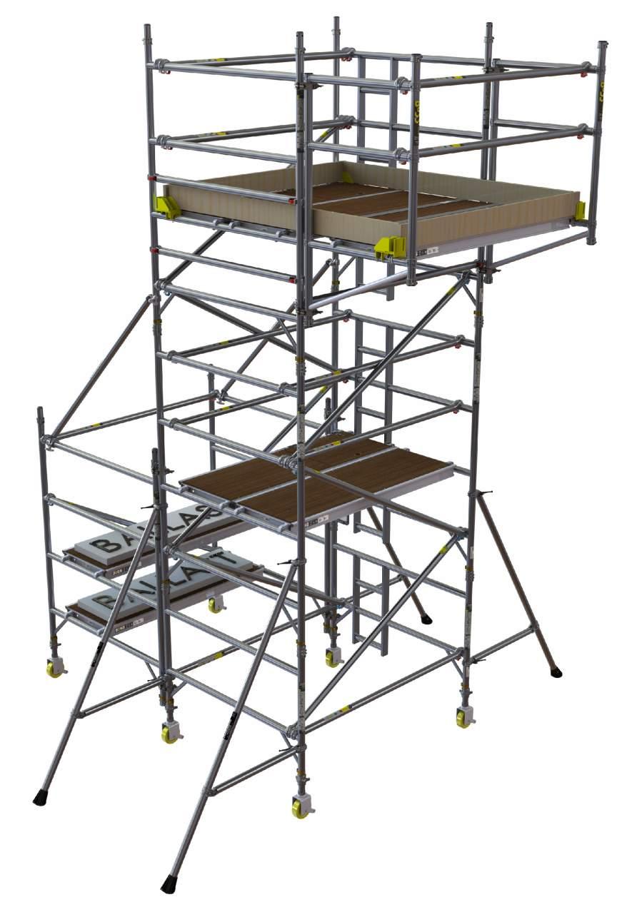
1 INSTRUCTIONmanual BoSS COMPACT SIDE CANTILEVER TOWER SCAFFOLD 3T Method - Through the Trap Door
2 Drawn: 26/02/2018 Issue: E Page: 2 OF 21 CONTENTS Safety First Component Diagram Component Quantities & Safety Data Schedules Build Method Pre-use Safety Inspection Checklist Instruction manual EN IM - en
3 Drawn: 26/02/2018 Issue: E Page: 3 OF 21 SAFETY FIRST Introduction Please read this guide carefully. Please note that diagrams are for illustrative purposes only. User guides are also available to download from our website at BoSS mobile aluminium towers are light-weight scaffold towers used throughout the building and construction industry for both indoor and outdoor access solutions where a stable and secure platform is required. Ideal for maintenance and installation work or short-term access, the highly versatile towers provide a strong working platform for a variety of heights. The law requires that personnel erecting, dismantling, altering, inspecting or using towers must be competent. Any person erecting the product described in this user guide must have a copy of this guide. For further information on the use of mobile access and working tower visit our website at or consult the PASMA website at Verification and assessment documentation is held by Youngman Group Ltd. If you need further information, design advice, additional guides or any other help with this product, please contact Youngman on +44 (0) or uk.customercare@wernerco.com Safe Use - Check overhead that the area into which the structure is to be erected contains no obstructions, particularly electrical or radio radiation hazards. - The structure is highly conductive and must not be used when there is a risk of electrical arcing. - Ensure the ground on which the mobile access tower is to be erected is capable of supporting the tower in use. - Before each use: Check that each prefabricated tower scaffold is complete and correctly assembled. Check that the prefabricated tower scaffold is vertical and make any adjustments as required. Check that no environment changes will affect the safe use of the structure. - Adjustable legs should only be used for levelling purposes and never to gain extra height. - Do not use ladders, steps, boxes or similar, to gain additional working height. - Only climb the tower from the inside using the access method provided. - Tower scaffolds are not designed to be lifted or suspended. - Beware of horizontal forces (e.g. power tools) which could generate instability. Maximum horizontal force per working bay = 30kg - Tools and materials should be lifted using a reliable lifting material (e.g. a strong rope), employing a reliable knot (e.g. clove hitch), to ensure safe fastening and always lift within the footprint of the prefabricated tower scaffold (i.e. within the area bounded by the stabilisers). - Use good manual handling techniques when handling tower components. - Safe working loads, normally expressed in kn/m², are expressed below in kg per defined working area. B A C 1.8m LONG MAIN TOWER WITH 0.6m WIDE CANTILEVER DEFINED WORKING AREA A x Z B x Z C x Z MAX. SAFE WORKING LOAD (UNIFORMLY DISTRIBUTED INCLUDING PERSONS) 587 kg 275 kg 312 kg LOAD CLASS MAX NO. OF PERSONS * 2 2 Access Classes Z BALLAST PLATFORM(S) 2.5m LONG MAIN TOWER WITH 0.6m WIDE CANTILEVER DEFINED WORKING AREA A x Z B x Z C x Z MAX. SAFE WORKING LOAD (UNIFORMLY DISTRIBUTED INCLUDING PERSONS) 715 kg 275 kg 440 kg LOAD CLASS MAX NO. OF PERSONS * 2 2 * Persons are assumed to be 122kg (Reference to HSE - Revision of body size criteria in standards Protecting people who work at height - Research report 342) The Access Class provided for climbing this tower is: Access Class 'D' (Vertical Ladder).
4 Drawn: 26/02/2018 Issue: E Page: 4 OF 21 SAFETY FIRST Lifting of Individual Tower Components - Raising and lowering components, tools and/or materials by rope should be conducted within the tower base (i.e. within the area bounded by the stabilisers). Ensure that the safe working load of the supporting decks and the tower structure is not exceeded. Movement of the assembled prefabricated tower scaffold Ensure gloves or other suitable hand protection is worn. BEFORE The safe movement of any prefabricated tower scaffold shall be included in a specific risk assessment and take into account: - Site conditions: Ground surface (such as potholes, unstable surfaces, inclines) Overhead obstructions (such as live electrical cables or building members) - Wind conditions - Dimensions of the tower structure (a shorter tower will be more stable during movement - see PASMA guidance) - Consequences of overturning If the site conditions are not adequate to permit the safe movement of a mobile tower structure, then it must not be moved. DURING - Mobile tower structures shall be moved with the upmost caution: Remove cantilever by reversing assembly steps 12, 11 & 10. Remove ballast. Any stabilisers fitted must remain in position and raised no more than 25mm from the ground. Prefabricated tower structures must only be pushed using manual effort at or near the base. Movement of a mobile tower structure shall be no faster than 0.25 m/s (very slow walking pace) and sufficient number of persons shall be used to ensure the movement is fully under control. No persons, tools or materials shall be left on the mobile tower structure during movement. - Ensure all castors are unlocked. - Beware of ground level and overhead obstructions, uneven or sloping ground, sudden changes of levels (holes, voids, kerbs). AFTER - Ensure all castors are locked. - Reposition stabilisers as per assembly step 6. - Replace ballast as per assembly step 7. - Replace cantilever as per assembly steps 10, 11, The pre-use checklist on the final page shall be used to determine tower integrity. Maintenance - Storage - Transport - All components and their parts should be regularly inspected to identify damage, particularly to joints. Lost or broken parts should be replaced and any tubing with indentation greater than 5mm shall be replaced. Adjustable leg threads should be cleaned and lightly lubricated to keep them free running. - Brace claws, frame interlock clips, trap door latches, Cam-Locks and platform wind locks should be regularly checked to ensure they lock correctly. - Refer to the BoSS Inspection Manual for detailed inspection and maintenance advice: - Components should be stored in clean, dry conditions with due care to prevent damage. - Ensure components are not damaged by excessive strapping forces when transported. Ballast Weights Ballast shall always be fitted when specified. Ballast must be of solid materials (i.e. not sand, water or other liquid or granular materials) and must be securely attached to the tower structure. Ballast weights placed at the base of the structure will increase tower self-weight, thereby increasing stability. Care must be taken to ensure that the weight of the ballast weights used is known, and that the total safe load on the structure, and particularly on the castors, is not exceeded. Use good manual handling techniques when handling ballast. See quantity schedule on page 8 and 9 for ballast information. Note: ballast uniformly distributed to a maximum of 275kg per deck.
.")
5 Drawn: 26/02/2018 Issue: E Page: 5 OF 21 SAFETY FIRST During Assembly, Use and Dismantling - As part of the risk assessment, wind conditions must be taken into account and reviewed regularly, depending on the duration the structure is on site. - The structure has been assessed for wind loads equating to 27 mph (43 kph, 12 m/s). - The effect of wind conditions on site must be considered prior to the assembly of a tower. The tower must not be used in wind speeds beyond 27 mph. If greater wind speeds are forecast, the tower must be dismantled while it is still safe to do so. - Sheets, tarpaulins, cladding or similar, must not be attached to the tower as these will significantly increase any side loads from wind and will potentially make the tower unstable. - Beware of wind turbulence, funnelling effects around buildings and updraughts on stairways. The maximum allowable side load on a tower is 30kg. - CAUTION: Excessive side loads due to working from the tower may cause the structure to become unstable. Special consideration should be given to side loads including vibrations. - Do not abuse equipment. Damaged, incorrect or incompatible components shall not be used. - The structure is highly conductive and must not be used when there is a risk of electrical arcing. - Exercise caution when touching unprotected metal components in extreme high or low temperatures. - If the tower is damaged in any way while in service, it shall not be used again until the damaged components are replaced. Ties This structure is designed to be self-supporting under the loading condition requirements of BS :2014 and does not require tying in. Consideration should be given to potential wind conditions if the tower is left unattended - see 'During Assembly, Use and Dismantling' section above. Tower Designation & Safety Data In accordance with the prefabricated tower scaffold standards, the Tower Designation & Safety Data shall be positioned at the base of the prefabricated tower scaffold as shown within the instruction manual, by means of the Tower Designation Information Assembly. It must be clearly visible so that users are aware of the conditions of safe use. Refer to Safety Data Schedule for content. Stabilisers Stabilisers shall always be fitted when specified. See quantity schedule on page 8 and 9. Attach one stabiliser to each corner of the tower as shown. Position the lower clamp so that the lower arm is as close to horizontal as possible. Adjust the position of the upper clamp to ensure the stabiliser foot is in contact with the ground. Ensure clamps are secure. 90


6 Drawn: 26/02/2018 Issue: E Page: 6 OF 21 SAFETY FIRST Assembly Procedure This tower structure must be assembled, and components oriented, in accordance with this instruction manual. Deviation from this instruction manual is not permitted. A minimum of two persons are recommend for assembly and disassembly of this prefabricated tower structure. The maximum number of persons permitted on the tower during assembly is stated in the safety data schedule. Platforms must be installed with vertical distances between them not exceeding 2m when assembling and dismantling. The maximum number of people on a working platform level permitted to simultaneously exert a horizontal load of 30kg is: - 1 person per bay for bays less than 4m long and - 2 persons per bay for bays greater than 4m in length Check that all components, tools and safety equipment are on site (refer to quantity schedule), undamaged and that they are functioning correctly, particularly the brace claw locking mechanism. Full inspection guidance can be found at. Damaged or incorrect components shall not be used. Component weights can be found in the quantity schedule and on the corresponding BoSS Product Datasheets. Check that the ground on which the tower structure is to be erected and moved is capable of supporting the tower in use and within the levelling limits of the tower system. Check overhead that the area into which the tower structure is to be built contains no obstructions, particularly electrical or radio radiation hazards. When positioning the tower take into account risk of collision with the tower e.g. from pedestrians, vehicles or doors. Secure doors (not fire exists) and windows where possible in the work area. Never stand on an unguarded platform positioned above the first rung of a tower structure. If your risk assessment shows it necessary, you may also need to guardrail platforms at this level. Tower components should be lifted using a reliable lifting material (e.g. a strong rope), employing a reliable knot (e.g. clove hitch), to ensure safe fastening and always lift within the footprint of the tower structure. Tower Designation & Safety Data content for the Tower Designation Information Assembly can be found in the Safety Data Schedule. This assembly must be positioned at the base of the prefabricated tower scaffold and clearly visible for users. Refer to Safety Data Schedule for content. Adjustable legs should only be used for levelling purposes and never to gain extra height. Ensure horizontal braces and guardrails are fitted correctly. Ensure interlock clips on frame members are in the 'locked' position. Ensure wind locks are engaged before moving onto the deck levels.
7 Drawn: 26/02/2018 Issue: E Page: 7 OF 21 COMPONENT DIAGRAM TOE BOARD HOLDER 1.8m CANTILEVER INFILL DECK 1.8m TOE BOARD 2.1m TOE BOARD 1.45m HORIZONTAL BRACE 1.98m BRACE ASSEMBLY CANTILEVER FRAME 2.0m 4 RUNG 1450 SPAN FRAME 2.0m 4 RUNG 1450 LADDER FRAME 1.8m TRAP DOOR DECK 1.8m FIXED DECK BALLAST TOWER DESIGNATION INFORMATION ASSEMBLY 1.0m 2 RUNG 1450 LADDER FRAME 2.1m DIAGONAL BRACE SWIVEL COUPLER ADJUSTABLE LEG & CASTOR 1.8m HORIZONTAL BRACE INSTRUCTION MANUAL STABILISER 1.0m 2 RUNG 1450 SPAN FRAME

8 Drawn: 26/02/2018 Issue: E Page: 8 OF 21 COMPONENT QUANTITY & SAFETY DATA SCHEDULE Note: The safety data specified within the schedule above which relates to the specific tower to be assembled must be transferred into the pre-defined boxes on the Tower Designation Information insert found in the Tower Designation Information Kit.

9 Drawn: 26/02/2018 Issue: E Page: 9 OF 21 COMPONENT QUANTITY & SAFETY DATA SCHEDULE Note: The safety data specified within the schedule above which relates to the specific tower to be assembled must be transferred into the pre-defined boxes on the Tower Designation Information insert found in the Tower Designation Information Kit.


10 Drawn: 26/02/2018 Issue: E Page: 10 OF m WORKING PLATFORM HEIGHT SHOWN 3.7m WORKING PLATFORM HEIGHT SHOWN BUILD PATTERN - TYPE 1 TOWER WORKING PLATFORM HEIGHTS: 1.2m, 3.2m, 5.2m BUILD PATTERN - TYPE 2 TOWER WORKING PLATFORM HEIGHTS: 1.7m, 3.7m, 5.7m 4.2m WORKING PLATFORM HEIGHT SHOWN 2.7m WORKING PLATFORM HEIGHT SHOWN BUILD PATTERN - TYPE 3 TOWER WORKING PLATFORM HEIGHTS: 2.2m, 4.2m, 6.2m BUILD PATTERN - TYPE 4 TOWER WORKING PLATFORM HEIGHTS: 2.7m, 4.7m Note: Decks and Guardrails omitted from views for clarity.


11 Drawn: 26/02/2018 Issue: E Page: 11 OF 21 When building a BoSS tower: - To comply with 'Work at Height Regulations' we show assembly procedures with platforms every 2 metres in height and the locating of guardrails in advance of climbing onto a platform to increase safety and reduce the risk of a fall. - Never stand on an unguarded platform positioned above the first rung of a tower. If your risk assessment shows it necessary, you may also need to guardrail platforms at this level. The procedure illustrated shows a 6.2m working height tower build. For alternative tower height build patterns see p. 10. Youngman recommend two persons are used to build BoSS Towers. Above 4.0m platform height, it is essential that at least two persons are used. Only climb the tower from the inside. Youngman recommend the 'Tower Designation & Safety Data' is recorded within the 'Tower Designation Information Assembly' before proceeding with the tower assembly. Refer to Safety Data Schedule for content. 1 Push Castor into Adjustable Leg. Push Castor/Leg Assembly into the 2 Rung Frame and lock the Castor. Repeat for the other side of the Frame. It is recommended, for ease of levelling, that a maximum gap of 50mm is left between the bottom of the leg and the adjustable nut. Ensure all Castors are locked. Note: Adjustable Legs are for levelling only. They are not to be used to gain extra height at the working level.


12 Drawn: 26/02/2018 Issue: E Page: 12 OF 21 2 Fit one Horizontal Brace (red catch) onto the vertical of the 2 Rung Span Frame, just below the bottom rung with the open section of the claw facing outwards. Note: All locking claws must be opened before fitting and positively locked into position. 3 Repeat step 1 for the 2 Rung Ladder Frame and position it as shown and fit the other end of the Horizontal Brace onto the vertical, just below the bottom rung of Span Frame. Fit the second Horizontal Brace between the bottom rungs on the other side of the frame to square the structure. Ensure all claws are positively locked into position. The structure must be vertical to within 1cm per metre. Ensure the frames are vertical and level by checking with a spirit level and setting the Adjustable Legs as required.


13 Drawn: 26/02/2018 Issue: E Page: 13 OF 21 4 Fit the 4 Rung Ladder Frame and the 4 Rung Span Frame to the structure base. Fit four Diagonal Braces in positions shown. Ensure all claws are positively locked into position. Ensure inbuilt ladders are aligned. RECORD TOWER DESIGNATION & SAFETY DATA WITHIN THE TOWER DESIGNATION INFORMATION ASSEMBLY AND ATTACH TO THE TOWER IN POSITION SHOWN. REFER TO SAFETY DATA SCHEDULE FOR CONTENT. For alternative tower height build patterns see p.10. Ensure interlock clips on frame members are in the 'locked' position.


14 Drawn: 26/02/2018 Issue: E Page: 14 OF 21 5 Fit the Trap Door Deck and Fixed Deck on the fourth rungs of the tower. The Trap Door Deck must be oriented such that the trap door opens towards the outside of the structure. Ensure the deck wind locks are engaged. From the protected trap door position, fit guardrails at 0.5m and 1.0m (in that order) above the platform level. Do not climb on the deck until it is fully guardrailed. Ensure all claws are positively locked into position. Ensure trap door is directly aligned with inbuilt ladder. Ensure all wind locks are engaged. 3T - Protected Trap Door Position


15 Drawn: 26/02/2018 Issue: E Page: 15 OF 21 6 Fit four Stabilisers as shown. See p. 5 for details. Telescopic stabilisers must always be fully extended. Note: Position lower clamps so that the lower arm is as close to horizontal as possible. Adjust the position of the top clamp to ensure the stabiliser foot is in firm contact with the ground. Ensure clamps are secure.


 3.2 2.7 4.2 4.7 5.2 5.7 6.2 6.7 7.2 7.")


16 Drawn: 26/02/2018 Issue: E Page: 16 OF 21 7 Fit two Castors with Adjustable Legs to the outer tubes of two 4 Rung Span Frames and link them to the tower structure using four Swivel Couplers. The couplers should be fitted below the 1st and above the 4th rungs of the tower structure. Fit one Horizontal Brace followed by one Diagonal Brace, as shown. Fit Fixed Decks to support ballast. Ensure all wind locks are engaged. Ensure all claws are positively locked into position. Note: ballast uniformly distributed to a maximum of 275kg per deck. The tower must be vertical to within 1cm per metre. For alternative tower height build patterns see p. 10. Note: Fit Ballast at this stage For Ballast information, 8 and 9. QUANTITY OF FIXED DECKS TO SUPPORT BALLAST 1.8m LONG MAIN TOWER WITH 0.6m WIDE CANTILEVER COMPOSITE CODE WORKING HEIGHT (m) PLATFORM HEIGHT (m) NO. OF FIXED DECKS QUANTITY OF FIXED DECKS TO SUPPORT BALLAST 2.5m LONG MAIN TOWER WITH 0.6m WIDE CANTILEVER COMPOSITE CODE WORKING HEIGHT (m) PLATFORM HEIGHT (m) NO. OF FIXED DECKS


17 Drawn: 26/02/2018 Issue: E Page: 17 OF 21 8 Fit the next level of Ladder Frame and Span Frame making sure that interlock clips are engaged. Fit two Diagonal Braces, as shown. Fit two 1.98m Brace Assemblies. Ensure all claws are positively locked into position. Ensure inbuilt ladders are aligned. Tie the frames together using the 1.98m Brace Assemblies, as shown. Ensure clamps are fully tightened. Ensure Brace Assemblies span End Frame joint.


 above the")


18 Drawn: 26/02/2018 Issue: E Page: 18 OF 21 9 Fit the Fixed Deck and Trap Door Deck 2.0m above the previous level. Ensure all wind locks are engaged. Note the orientation of the trap door. From the protected trap door position, fit guardrails at 0.5m and 1.0m (in that order) above the platform level. Fit one Diagonal Brace in position shown. Ensure all claws are positively locked into position. Ensure trap door is directly aligned with inbuilt ladder. Do not climb on the deck until it is fully guardrailed. TEMPORARY GUARDRAILS When building beyond 4.2m platform height: Before fitting Cantilever Frames ensure end frame joints on opposite tower face are tied together as shown. Ensure clamps are fully tightened. Ensure Brace Assemblies span the end frame joint.


19 Drawn: 26/02/2018 Issue: E Page: 19 OF Fit two Cantilever Frames, as shown. Note position of couplers. Fit two 1.45m Horizontal Braces in positions shown. Fit one 1.8m Horizontal Brace in position shown. Ensure all claws are positively locked into position. Ensure wing nuts are fully tightened. 11 From the protected position within the main tower, fit one Fixed Deck and Infill Deck, as shown. Fit two extra guardrails at the end of the Cantilever Frames, as shown. Ensure all wind locks are engaged. Ensure all claws are positively locked into position. Do not walk out onto the cantilever bay until it is fully assembled and guardrailed. Remove four end plugs Position infill deck Engage all wind locks


20 Drawn: 26/02/2018 Issue: E Page: 20 OF Fit Toe Board Holders and Toe Boards around edges of top decks, as shown. Temporary guardrails to be stored in positions shown. Ensure all claws are positively locked into position. THE TOWER IS NOW COMPLETE. To dismantle a BoSS tower: Simply follow the assembly steps in reverse, ensuring that the 3T method is followed.
21 Drawn: 26/02/2018 Issue: E Page: 21 OF 21 PRE-USE SAFETY INSPECTION CHECKLIST Pre-use Safety Inspection Checklist Tower structure upright & level Castors locked & legs correctly adjusted Horizontal & diagonal braces fitted Stabilisers fitted as specified Platforms located & wind locks engaged 0.89m & 1.98m brace assemblies fitted (when specified) Interlock clips engaged Toe boards located Guardrails fitted correctly & positively locked Infill decks fitted correctly Ballast fitted as specified Tower designation information present This checklist should be actioned at intervals determined by the manager. This checklist should also be actioned if the tower has been moved or modified, if any damage is suspected or if there are any changes to the local environment that may affect tower stability. Head Office and Customer Services The Causeway, Maldon, Essex. CM9 4LJ. United Kingdom INSTRUCTION MANUAL PART NO t: +44 (0) f: +44 (0) e: uk.customercare@wernerco.com w:
SIDE CANTILEVER TOWER SCAFFOLD. 3T - Through the Trapdoor Method USER GUIDE
 SIDE CANTILEVER TOWER SCAFFOLD 3T - Through the Trapdoor Method USER GUIDE Contents Safety First Component Diagram Component Quantity & Safety Data Schedule Build Method Pre-use Safety Inspection Checklist
END LINKED TOWER SCAFFOLD. 3T Method - Through The Trapdoor USER GUIDE
 ND LINKD TOWR SCAFFOLD 3T Method - Through The Trapdoor USR GUID Contents Safety First Component Diagram Component Quantity & Safety Data Schedule Build Method Pre-use Safety Inspection Checklist 2 7 8
INSTRUCTION MANUAL MOBILE ACCESS TOWER
 INSTRUCTION MANUAL MOBILE ACCESS TOWER CONTENTS Safety First.......... 3-6 Component Diagrams......... 7-9 Component Quantity & Safety Data Schedule.... 10 Build Method.......... 11-24 Pre-use Safety Inspection
STAIRMAX 700. Camlock Guardrail Aluminium Tower 3T - Through the Trapdoor USER GUIDE
 STAIRMAX 700 Camlock Guardrail Aluminium Tower 3T - Through the Trapdoor USER GUIDE Contents Safety First Component Diagram Quantity Schedule Build Method Pre-use Safety Inspection Checklist 2 10 11 12
STAIRMAX 700 MK2 USER GUIDE. Aluminium Tower 700 Climbing Rung. 3T - Through The Trapdoor Method
 STAIRMAX 700 MK2 Aluminium Tower 700 Climbing Rung 3T - Through The Trapdoor Method USER GUIDE Contents Safety First Component Diagram Component Quantity & Safety Data Schedule Build Method Pre-use Safety
Mobile Towers - 3T Method
 Safety First Safety First INTRODUCTION SAFE USE Mobile Towers - 3T Method Please read this guide carefully. Please note that diagrams are for illustrative purposes only. User guides are also available
CLIMA 3T. Mobile Aluminium Tower with Climbing Frame 1450/850 3T - Through the Trapdoor Method USER GUIDE
 CLIMA 3T Mobile Aluminium Tower with Climbing Frame 1450/850 3T - Through the Trapdoor Method USER GUIDE Safety First Mobile Towers - 3T Method Introduction Please read this user guide carefully. Please
CLIMA 3T. Mobile Aluminium Tower with Climbing Frame 1450/850 3T - Through the Trapdoor Method USER GUIDE
 CLIMA 3T Mobile Aluminium Tower with Climbing Frame 1450/850 3T - Through the Trapdoor Method USER GUIDE Safety First Mobile Towers - 3T Method INTRODUCTION Please read this Userguide carefully. Please
CLIMA AGR. Mobile Aluminium Tower with Climbing Frames 1450/850 Camlock Advanced Guardrail USER GUIDE
 CLIMA AGR Mobile Aluminium Tower with Climbing Frames 1450/850 Camlock Advanced Guardrail USER GUIDE Contents Safety First Safety Checklist Quantity Schedules Assembly and Dismantling Procedure Toe Boards
LADDERSPAN 3T USER GUIDE. Mobile Aluminium Tower 1450/850 Ladderspan. 3T - Through the Trapdoor Method
 LADDERSPAN 3T Mobile Aluminium Tower 1450/850 Ladderspan 3T - Through the Trapdoor Method USER GUIDE Safety First Mobile Towers - 3T Method INTRODUCTION Please read this user guide carefully. Please note
BoSS. Mobile Aluminium Tower 1450/850 Ladderspan. 3T - Through the Trapdoor Method
 BoSS Mobile Aluminium Tower 1450/850 Ladderspan 3T - Through the Trapdoor Method USER GUIDE Edition November 2011 Safety First Mobile Towers - 3T Method INTRODUCTION Please read this guide carefully. Please
Safety First Mobile Towers - 3T Method INTRODUCTION
 BoSS Room-Mate 3T - Through the Trap Method Safety First Mobile Towers - 3T Method INTRODUCTION Please read this guide carefully. Please note that diagrams are for illustrative purposes only. User guides
BoSS Clima USER GUIDE. Mobile Aluminium Tower with Climbing Frame 1450/850. 3T - Through the Trapdoor Method
 BoSS Clima Mobile Aluminium Tower with Climbing Frame 1450/850 3T - Through the Trapdoor Method USER GUIDE Edition April 2009 Safety First Mobile Towers - 3T Method INTRODUCTION Please read this guide
Safety First Mobile Towers - 3T Method INTRODUCTION
 Safety First Mobile Towers - 3T Method INTRODUCTION Safety First SAFE USE BoSS Mobile Aluminium Tower 1450/850 Ladderspan 3T - Through the Trapdoor Method Please read this guide carefully. Please note
ROOM-MATE. 3T - Through the Trapdoor USER GUIDE
 ROOM-MATE 3T - Through the Trapdoor USER GUIDE Safety First Introduction Please read this user guide carefully. Please note that diagrams are for illustrative purposes only. User guides are also available
LADDERSPAN AGR. BoSS Camlock Advance Guardrail Mobile Aluminium Tower 1450/850 Frames USER GUIDE
 LADDERSPAN AGR BoSS Camlock Advance Guardrail Mobile Aluminium Tower 1450/850 Frames USER GUIDE Contents Safety First Safety Checklist Quantity Schedules Assembly and Dismantling Procedure Toe Boards Stabilisers
BoSS Room-Mate. 3T - Through the Trap Method
 BoSS Room-Mate 3T - Through the Trap Method User Guide Edition 2: 2010 Safety First Mobile Towers - 3T Method INTRODUCTION Please read this guide carefully. Please note that diagrams are for illustrative
SOLO 700. One Man Aluminium Tower 3T - Through the Trapdoor Method USER GUIDE
 SOLO 700 One Man Aluminium Tower 3T - Through the Trapdoor Method USER GUIDE Contents Safety First Component Diagram Quantity Schedules Stabilisers Build Method 2 7 9 10 11 1 BoSS SOLO 700 User Guide Safety
Safety First Mobile Towers - 3T Method INTRODUCTION. Please read this guide carefully. Please note that diagrams are for illustrative purposes only.
 BoSS Mobile Aluminium Tower 0/80 Ladderspan T - Through the Trapdoor Method Safety First Mobile Towers - T Method INTRODUCTION Please read this guide carefully. Please note that diagrams are for illustrative
BoSS SOLO 700. One Man Aluminium Tower EN /4 EN1298-IM-EN 3T - Through the Trap Door USER GUIDE
 BoSS SOLO 700 One Man Aluminium Tower EN1004-3-4/4 EN1298-IM-EN 3T - Through the Trap Door USER GUIDE Edition August 2013 Contents Safety First 2 Component Diagram 7 Quantity Schedules 9 Stabalisers 10
MiniMax USER GUIDE. Mobile Aluminium Trade Quality Access Tower System. 3T - Through The Trapdoor Method
 MiniMax Mobile Aluminium Trade Quality Access Tower System 3T - Through The Trapdoor Method USER GUIDE Contents Safety First Component Diagram Component Quantity & Safety Data Schedule Build Method Pre-use
Safety First Mobile Towers - 3T Method
 USER GUIDE Edition Aug 2011 MiniMax Mobile Aluminium Trade Quality Access Tower System 3T - Through the Trapdoor Method Safety First Mobile Towers - 3T Method INTRODUCTION Please read this guide carefully.
Inspect components prior to erection. Inspect tower prior to use. Castors locked and legs correctly adjusted. Stabilisers fitted as specified
 Introduction This Guide is designed to provide you with step bystep instructions to ensure that your system is erected with themaximum of ease and safety. Before assembly, please read thesafety notes.
Safety First Mobile Towers - 3T Method
 Safety First Mobile Towers - 3T Method INTRODUCTION Please read this guide carefully. Please note that diagrams are for illustrative purposes only. User guides are also available to download from our website
Mobile Tower 3T Method (Through The Trapdoor) Please read this guide carefully. Please note that diagrams are for illustrative purposes only.
 Please read this guide carefully. Please note that diagrams are for illustrative purposes only.") Mobile Tower 3T Method (Through The Trapdoor) INTRODUCTION Please read this guide carefully. Please note that diagrams are for illustrative purposes only. LOYAL mobile aluminium towers are light-weight
Mobile Tower 3T Method (Through The Trapdoor) INTRODUCTION Please read this guide carefully. Please note that diagrams are for illustrative purposes only. LOYAL mobile aluminium towers are light-weight
This User Guide provides you with step by step instructions to ensure your system is erected easily and safely.
 INTRODUCTION Please read this guide carefully. Please note that diagrams are for illustrative purposes only. Trade King 730 mobile aluminium towers are light-weight scaffold towers used throughout the
BoSS Climalite Camera and lighting tower
 Contents Safety First Safety First Quantity Schedules Toeboard 2 9 13 33 INTRODUCTION Please read this guide carefully. Please note that diagrams are for illustrative purposes only. User guides are also
1450/850. Instruction Manual. Mobile Access Tower
 A SAFER WAY TO REACH NEW HEIGHTS 1450/850 Instruction Manual Mobile Access Tower 3T - Through the trap method Introduction This Assembly Guide is intended to provide you with step-by-step instructions
8 Rung Industrial Tower
 A SAFER WAY TO REACH NEW HEIGHTS 8 Rung Industrial Tower Instruction Manual Mobile Access Tower 3T - Through the trap method Introduction This Assembly Guide is intended to provide you with step-by-step
A SAFER WAY TO REACH NEW HEIGHTS. Instruction Manual. Mobile Access Tower. 3T - Through the trap method
 A SAFER WAY TO REACH NEW HEIGHTS UTS1450/850 Instruction Manual Mobile Access Tower 3T - Through the trap method Introduction This Assembly Guide is intended to provide you with step-by-step instructions
Span 300 Instruction Manual
 Span 300 Instruction Manual DESIGNATION SPAN300 Double Width EN 1004 3 8/12 XXCD SPAN 300 Single Width EN 1004 3 8/8 XXCD CEN designation of this instruction manual EN 1298 IM en Rev-00 WARNING NEVER STAND
Span 500. Elite Instruction Manual. DESIGNATION SPAN 500 Double Width EN /12 XXXD SPAN 500 Single Width EN /8 XXXD
 Span 500 Elite Instruction Manual DESIGNATION SPAN 500 Double Width EN 1004 3 8/12 XXXD SPAN 500 Single Width EN 1004 3 8/8 XXXD CEN designation of this instruction manual EN 1298 IM en Rev-02 WARNING
Span 300 Manual. DESIGNATION EN1004 CEN 1298 IM - en. CEN designation of this instruction manual EN 1298 IM en
 Span 300 Manual DESIGNATION EN1004 CEN 1298 IM - en CEN designation of this instruction manual EN 1298 IM en WARNING NEVER STAND ON AN UNGUARDED PLATFORM SAFE WORKING LOADS AND WORKING HEIGHTS The safe
Span 400 Instruction Manual
 Span 400 Instruction Manual DESIGNATION SPAN 400 Double Width EN 004 3 8/2 XXCD SPAN 400 Single Width EN 004 3 8/8 XXCD CEN designation of this instruction manual EN 298 IM en Rev-00 WARNING NEVER STAND
Span 400 Series Instruction Manual
 Span 400 Series Instruction Manual DESIGNATION 400 400 004 3 8 2 400 400 004 3 8 8 CEN designation of this instruction manual EN 298 IM en Rev-0 WARNING NEVER STAND ON AN UNGUARDED PLATFORM SAFE WORKING
3T - Through The Trapdoor Method
 ALTO HEAVY DUTY SINGLE WIDTH LADDERSPAN TOWER Mobile Aluminium Access Tower ISSUE 5 Instruction Manual EN 1298-IM-EN The ALTO HD Ladderspan Tower is certified to BS EN 1004:2004 3T - Through The Trapdoor
Instruction Manual. DESIGNATION SPAN 500 Double Width EN /12 XXXD SPAN 500 Single Width EN /8 XXXD
 Instruction Manual DESIGNATION SPAN 500 Double Width EN 1004 3 8/12 XXXD SPAN 500 Single Width EN 1004 3 8/8 XXXD CEN designation of this instruction manual EN 1298 IM en Rev-02 WARNING NEVER STAND ON
Assembly Instructions
 Assembly Instructions BAILEY Ladders Mini Rise Mobile Scaffold Pack Schedule Working Height (m) 2.9 3.7 5.7 Platform Height (m) 0.9 1.7 3.7 Description Wt Pack Qty. Base Pack 34kg 1 1 1 Guardrail Pack
COMPONENT SCHEDULE SINGLE WIDTH SPAN TOWERS WITH LADDER FRAMES TO BSEN RUNG STARTER FRAMES
 COMPONENT SCHEDULE SINGLE WIDTH SPAN TOWERS WITH LADDER S TO BSEN 1004-2004 STARTER S PLATFORM HEIGHT METRIC 2.4 2.9 3.4 3.9 4.4 4.9 5.4 5.9 6.4 6.9 7.4 7.9 DESCRIPTION IMPERIAL 7 10 9 6 11 2 12 10 14
3T - Through The Trapdoor Method
 ALTO MEDIUM DUTY STAIRWELL TOWER Aluminium Access Tower ISSUE 3 Instruction Manual EN 1298-IM-EN The ALTO MD Stairwell Tower 3T - Through The Trapdoor Method Lakeside Industries Ltd www.altoaccess.com
Industrial Aluminium Towers
 Industrial Aluminium Towers SINGLE WIDTH LADDERSPAN & VERTICAL LADDER ERECTION MANUAL TO BS-EN 1004-2004 Using 2 rung frames (Recommended) Using guardrail frames HORIZONTAL BRACE 1.8m (2040) 2.7m (2041)
Industrial Aluminium Towers
 Industrial Aluminium Towers SINGLE WIDTH LADDERSPAN & VERTICAL LADDER ERECTION MANUAL HORIZONTAL BRACE 1.8m (2040) 2.7m (2041) REVISED EDITION TOE BOARD 1.8m (2065) 2.7m (2067) LADDERSPAN TRAP PLATFORM
Industrial Aluminium Towers
 Industrial Aluminium Towers SINGLE WIDTH LADDERSPAN & VERTICAL LADDER ASSEMBLY GUIDE TO BS-EN 1004-2004 Using 2 rung frames (Recommended) Using Guardrail frames HORIZONTAL BRACE 1.8m (2040) 2.7m (2041)
MOBILE ACCESS TOWER INSTRUCTION MANUAL SHALLOW BRACE. Incorporating the 3T method of assembly
 MOBILE ACCESS TOWER Incorporating the 3T method of assembly SHALLOW BRACE INSTRUCTION MANUAL 2 INTRODUCTION This instruction manual contains all the information required to correctly assemble the OCTO
Industrial Aluminium Towers
 HORIZONTAL 1.8m (2040) 2.7m (2041) TOE BOARD 1.8m (2066) 2.7m (2068) Industrial Aluminium Towers DOUBLE WIDTH SPAN & VERTICAL ASSEMBLY GUIDE TO BS-EN 1004-2004 Using the 3T (Through the Trap ) Assembly
Snappy Ladder 300 Instruction Manual
 Snappy Ladder 300 Instruction Manual DESIGNATION: SNAPPY LADDER 300 EN 1004 3 4/4 XXCD CEN designation of this instruction manual EN 1298 IM en Rev-01 This assembly instruction is designed to provide a
SAFE ERECTION AND USE OF ALUMINIUM TOWERS/SCAFFOLDS
 SAFE ERECTION AND USE OF ALUMINIUM TOWERS/SCAFFOLDS PERSONNEL DIVISION Revised 2002 CONTENTS Page 1 INTRODUCTION 1 2 APPLICATION 1 3 ERECTION AND INSPECTION 1 4 ERECTION 1 4.1 Before erection of tower
Low Level Access Platform
 ALTO LOW LEVEL ALTO ROOM SCAFFOLD Low Level Access Platform ISSUE 2 Instruction Manual EN 1298-IM-EN The ALTO Room Scaffold System is certified to BS 1139-6:2014 Lakeside Industries Ltd www.altoaccess.com
Single Width Tower Assembly Guide
 Unit 1 Bellingham Trading Estate Franthorne Way London SE6 3BX T: 0845 257 599 E: info@scaffold-tower.co.uk W: www.scaffold-tower.co.uk This document will provide all users of Lewis Access Towers with
Tower ASSEMBLY GUIDE
 Tower ASSEMBLY GUIDE Contents Introduction Section Contents Introduction Know Your MiTOWER Know Your MiTOWER s Components Know Your Kit List and Specifications Know Your Storage and Transport Pack Safety
EASY-SET SCAFFOLD TOWER OPERATIONAL SAFETY AND ASSEMBLY INSTRUCTIONS MODEL: AL-Q0107. Customer Service
 MODEL: AL-Q0107 EASY-SET SCAFFOLD TOWER OPERATIONAL SAFETY AND ASSEMBLY INSTRUCTIONS Picture may differ from actual product. READ THESE INSTRUCTIONS CAREFULLY BEFORE USING THIS PRODUCT. KEEP THIS MANUAL
EASY-SET SCAFFOLD TOWER OPERATIONAL SAFETY AND ASSEMBLY INSTRUCTIONS MODEL: AL-Q0106. Customer Service
 MODEL: AL-Q0106 EASY-SET SCAFFOLD TOWER OPERATIONAL SAFETY AND ASSEMBLY INSTRUCTIONS Picture may differ from actual product. READ THESE INSTRUCTIONS CAREFULLY BEFORE USING THIS PRODUCT. KEEP THIS MANUAL
A-0312 ASSEMBLY GUIDE
 760265-A-0312 ASSEMBLY GUIDE 1 Contents Section Contents Introduction Know Your MiTOWER Know Your MiTOWER s Components Know Your Kit List and Specifications Know Your Storage and Transport Pack Safety
Rolling Towers. Layher Uni Light Tower Instructions for Assembly and Use. Mobile working platforms according to DIN EN 1004:
 Instructions for ssembly and Use Mobile working platforms according to DIN EN 00:00-03 Working platform 0.7 x.8 m max. working height: indoors.3 m outdoors.3 m Rolling Towers Load bearing capacity.0 kn/m
LEWIS Miniscaff Folding Tower Assembly Guide
 LEWIS Miniscaff Folding Tower Assembly Guide This document is a complete guide for the LEWIS Miniscaff Towers The user should read the entire contents of this document before commencing assembly and pay
Assembly Instructions
 MULTI-FUNCTIONAL SCAFFOLD UNIT + STABILIZER LEGS 1. SCAFFOLD 2. LADDER 3.TRESTLE 2 1 3 Assembly Instructions CODE: 126431 Parts List Specifications: - Width: 1.2m - Length: 1.6m - Scaffold Height: 3.4m
ASSEMBLY INSTRUCTION ROLLING TOWER RT 1400 & RT 1400XR ROLLING TOWER RT 750 & RT 750XR STAIR TOWER ST 1400 FOLDABLE TOWER FT 750 & FT 750XR
 ASSEMBLY INSTRUCTION ROLLING TOWER RT 1400 & RT 1400XR ROLLING TOWER RT 750 & RT 750XR STAIR TOWER ST 1400 FOLDABLE TOWER FT 750 & FT 750XR EN 1298 - IM - en SC1809 12 SAFETY IN EVERY STEP wibeladders.com
Mini-Max Access Tower System Data-Sheets
 Date: Jan 2012 Page 1 Mini-Max Access Tower System Data-Sheets ISSUE: D DATE: Jan 2012 Youngman Group Ltd Page 1 of 26 MINI-MAX DATA SHEET CONTENTS Date: Jan 2012 Page 2 Description Page No ------------------------------------------------
EASY-SET SCAFFOLD TOWER OPERATIONAL SAFETY AND ASSEMBLY INSTRUCTIONS MODEL: AL-Q0108. Customer Service
 MODEL: AL-Q0108 EASY-SET SCAFFOLD TOWER OPERATIONAL SAFETY AND ASSEMBLY INSTRUCTIONS Picture may differ from actual product. READ THESE INSTRUCTIONS CAREFULLY BEFORE USING THIS PRODUCT. KEEP THIS MANUAL
Rolling Towers. Layher Rolling Towers Uni Wide. Safety Structure Instructions for Assembly and Use. Mobile working platforms to DIN EN 1004:
 Layher Rolling Towers Uni Wide Safety Structure Instructions for Assembly and Use Mobile working platforms to DIN EN 1004:2005-03 Working platform 1.5 x 2.85 m Rolling Towers max. working height: indoors
GENERAL SAFETY RULES DOUBLE WIDTH 232 (NARROW RUNG) 3T INSTRUCTION MANUAL DISMANTLING NOTES: The 232 Tower Approved to the requirements of BS EN 1004
 3T INSTRUCTION MANUAL DISMANTLING NOTES: The 232 Tower Approved to the requirements of BS EN 1004") GENERAL SAFETY RULES DOUBLE WIDTH 232 (NARROW RUNG) 3T INSTRUCTION MANUAL The 232 Tower Approved to the requirements of BS EN 1004 MAX SAFE WORKING LOAD FOR STRUCTURE: 750KG MAX SAFE WORKING LOAD FOR PLATFORM:
GENERAL SAFETY RULES DOUBLE WIDTH 232 (NARROW RUNG) 3T INSTRUCTION MANUAL The 232 Tower Approved to the requirements of BS EN 1004 MAX SAFE WORKING LOAD FOR STRUCTURE: 750KG MAX SAFE WORKING LOAD FOR PLATFORM:
AGR TOWER. Standard Features include. Tower Assembly Training Available
 AGR TOWER The Euro Tamper Proof Advanced Guardrail is another solution to safe tower assembly. The ergonomic design lends itself to quick easy assembly and provides collective fall prevention before the
ASSEMBLY GUIDE FOR USE WITH EURO TOWERS LADDER FRAME 3T TOWER SYSTEMS ONLY
 ASSMBLY GUID FOR US WITH URO TOWRS LADDR FRAM 3T TOWR SYSTMS ONLY AVAILABL FOR 2M, 2.5M and 3M PLATFORM LNGTHS and DOUBL WIDTH ND ON OPTIONAL GATD FRAM AVAILABL UPON RQUST Mobile access working towers
TOWER EXTENSION PACK 3 Model No. SSCL3. TOWER EXTENSION PACK 4 Model No. SSCL4 INSTRUCTIONS FOR: PLATFORM SCAFFOLD STAND. Model No. SSCL1.
 TOWER EXTENSION PACK 3 Model No. SSCL3 INSTRUCTIONS FOR: PLATFORM SCAFFOLD STAND Model No. SSCL1.V2 TOWER EXTENSION PACK 4 Model No. SSCL4 Thank you for purchasing a Sealey product. Manufactured to a high
Layher. Aluminium Rolling Towers. Layher SuperKlaxTower. Instructions for Assembly and Use
 Mobile access and working towers in accordance with: HD 1004; DIN 4422, Part 1 (Version 8/92) Working platform 2.8 x 2.8 m and 2.8 x 1.95 m Max. working height: in closed rooms 13.95 m, outdoors 10.0 m
ONE MAN TOWER. Instruction/safety manual
 ONE MAN TOWER Instruction/safety manual The UTS One Man Tower is both quick and easy to assemble and can be erected and dismantled by a single person. Safety Information IMPORTANT: Never use the ONE MAN
Thanks for viewing this information PDF. There's more products, details, speci cation etc. on our website - CLICK THE LINKS ABOVE
 Thanks for viewing this information PDF There's more products, details, speci cation etc. on our website - CLICK THE LINKS ABOVE T ASSEMBLY GUIDE - Single Width This assembly guide is designed to provide
Mobile Tower Scaffold. 1. INTRODUCTION 2. REGULATIONS 3. PRIOR TO ERECTION 4. MOVING A TOWER 5. INSPECTION 6. HAZARDS
 Mobile Tower Scaffold. 1. INTRODUCTION 2. REGULATIONS 3. PRIOR TO ERECTION 3.1 Before Erection of Tower 3.2 Stability of Tower 3.3 Access & Guardrails 3.4 Height 3.5 Outriggers & Stabilizers 3.6 Tying-in
 Instruction Manual Span Scaffolds! W A R N I N G! Before using Instant UpRight Scaffolds, read, understand and follow all Safety Rules, Erection Instructions and Maintenance Rules. Keep this manual for
Instruction Manual Span Scaffolds
 Instruction Manual Span Scaffolds QUALITY & STRENGTH YOU CAN TRUST! W A R N I N G! Before using Instant UpRight Scaffolds, read, understand and follow all Safety Rules, Erection Instructions and Maintenance
1 Man Mobile Aluminium Tower System
 1 Man Mobile Aluminium Tower System Euro one, quick assembly, one person aluminum mobile tower Easy to erect and dismantle by one person with the base unit forming a trolley for fast storage and transportation.
GENERAL SAFETY RULES. INSTRUCTION MANUAL (Platform Heights 1.1m, 2.1m, 3.1m & 4.1m)
") GENERAL SAFETY RULES Risk Assessment A risk assessment MUST be carried out before using any access equipment or work at height. Always wear the correct PPE as identified by the risk assessment. 1. Check
GENERAL SAFETY RULES Risk Assessment A risk assessment MUST be carried out before using any access equipment or work at height. Always wear the correct PPE as identified by the risk assessment. 1. Check
USER S MANUAL HAKI PUBLIC ACCESS STAIR
 USER S MANUAL HAKI PUBLIC ACCESS STAIR HAKI AB 2018 Important information HAKI s product liability and user s manuals apply only to scaffolds that are entirely composed of components that have been made
USER S MANUAL HAKI PUBLIC ACCESS STAIR
 USER S MANUAL HAKI PUBLIC ACCESS STAIR HAKI AB 2017 Important information HAKI s product liability and user s manuals apply only to scaffolds that are entirely composed of components that have been made
hss.com / Safety / Value / Availability / Support The 2013 HSS Guide to Working Safely at Height
 The 2013 HSS Guide to Working Safely at Height Working Safely at Height - Your Guide to the Law 2011 / 2012-40 fatal injuries to workers and over 3,000 major injuries as a result of a fall from height
WORKING AT HEIGHT. The company will comply with the Work at Height Regulations 2005, its schedules and Codes of Practice.
 WORKING AT HEIGHT The company will comply with the Work at Height Regulations 2005, its schedules and Codes of Practice. Principally this means that we comply with the hierarchy of risk in that we shall:
Rolling scaffold single/double width Safe-Quick Guardrail RS TOWER 51/52/54
 Rolling scaffold single/double width Safe-Quick Guardrail RS TOWER 51/52/54 1. EN English Instruction manual EN1298 IM EN 739411-A-0718 EN 1. Introduction This manual applies exclusively to folding and
USER S MANUAL HAKI COMPACT STAIR TOWER
 USER S MANUAL HAKI COMPACT STAIR TOWER HAKI AB 2018 Important information HAKI s product liability and user s manuals apply only to scaffolds that are entirely composed of components that have been made
RAPID-EPS PATENT PENDING
 SAFETY INSTRUCTIONS AND INSTALLATION GUIDE Rapid-Edge Protection Systems Document ref: MK 3 1108 Issue Date: Issued by:. Approved by: CONTENTS Safety instructions 3 Important 4 General 5 Product information..
SAFETY SYSTEM. G-Deck Consideration. Manual Handling
 INTRODUCTION The G-Deck load deck system is a high strength, low cost access platform which is quick to erect, durable and flexible enough to meet your site access needs. Safety is a priority and G-Deck
USER S MANUAL HAKI COMPACT STAIR TOWER
 USER S MANUAL HAKI COMPACT STAIR TOWER HAKI AB 2018 Important information HAKI s product liability and user s manuals apply only to scaffolds that are entirely composed of components that have been made
Uniscaff User Guide. Uniscaff. George Roberts Total Reliability of Supply. George Roberts Total Reliability of Supply
 George Roberts Total Reliability of Supply User Guide George Roberts Total Reliability of Supply www.scaffoldingsales.co.uk Tubes Scaffold Staircases Beams Formwork Fencing K-Lok User Guide Contents Introduction
As a scaffold user, Mr Scaffold recommends Method 1, but both options are suitable.
 20 EASYSCAF t TM The Next Level 1300 MR SCAFFOLD (1300 677 223) 12 Lagana Place Wetherill Park NSW 2164 Fax: (02)9725 5214 ABN: 65 088 652 144 Re: Workcover Update Feb 2011 Thankyou for purchasing your
User Manual. JUMBO FOLDING SCAFFOLD w/stairs & railing
 User Manual JUMBO FOLDING SCAFFOLD w/stairs & railing 1. Conditions / Disclamer JUMBO Stillads A/S does not assume or undertake any responsibility for the content of this booklet or for the application
Assembly and Use manual Rolling tower 5100 and 5200 Stair tower 5300 Folding tower 5400 and 5500 EN C
 en Assembly and Use manual Rolling tower 5100 and 5200 Stair tower 5300 Folding tower 5400 and 5500 EN 1004 760251-C-0911 www.altrex.com Relax. Het It s an is een Altrex. Altrex. 1 van 32 en NL Manual
Customer Support Manual. This booklet contains information on how to erect, dismantle and use Waco Kwikform Aluminum Scaffolding.
 Customer Support Manual This booklet contains information on how to erect, dismantle and use Waco Kwikform Aluminum Scaffolding. WACO CUSTOMER SUPPORT MANUAL Page 0 of 70 Index Page Number Safety Information..
Mobile Safety. EN Assembly and Use manual Rolling tower 4100 and 4200 Folding tower 4400-K C-0711.
 Mobile Safety EN Assembly and Use manual Rolling tower 4100 and 4200 Folding tower 4400-K2 EN 1004 760201-C-0711 www.altrex.com 1 of 32 EN Manual assembly and use General Copyright Altrex B.V. 2011 All
USER S MANUAL. HAKI Loading Tower
 USER S MANUAL HAKI Loading Tower HAKI AB 2018 Important information HAKI s product liability and user s manuals apply only to scaffolds that are entirely composed of components that have been made and
Adjusta Minit Anti-Surf
 Adjusta Minit Anti-Surf The One Piece Adjustable Folding Work Platform» New slip resistant front feet» Adjustable to 4 different platform levels» Guardrail automatically in place» No loose components»
Safety on Heights: Our Policy
 11/17/14 Safety on Heights: Our Policy Only volunteers over the age of 18 are allowed to work on heights of more than six feet off the ground. This includes all work on scaffolds. Only volunteers who are
LAYHER ACCESS TECHNOLOGY CATALOGUE
 LAYHER ACCESS TECHNOLOGY CATALOGUE Edition 04.2018 Ref. No. 8118.229 Quality management certified according to ISO 9001:2008 ROLLING TOWERS FROM PAGE 34 ALU BRIDGING BEAM FROM PAGE 24 NOTICE All dimensions
Scaffolding. Safety Guide. STOP! Before you climb
 Scaffolding Safety Guide Printed FEB 2015 rebr. AUG 2016 Contents Safety Guide Disclaimer... 1 Safety Guide Objectives... 2 Roles & Responsibilities of Workplace Parties Employers, Supervisors, Workers...
Assembly and Usage Instructions Z 600 S-PLUS mobile scaffold tower with stabilisers Z 600 S-PLUS folding scaffold unit COMPACT
 09/2016 No. 291358 en Assembly and Usage Instructions Z 600 S-PLUS mobile scaffold tower with stabilisers Z 600 S-PLUS folding scaffold unit COMPACT 2 Contents en 1 General information... 4 1.1 Introduction...4
USER S MANUAL HAKI STAIR TOWER
 USER S MANUAL HAKI STAIR TOWER HAKI AB 2018 Important information HAKI s product liability and user s manuals apply only to scaffolds that are entirely composed of components that have been made and supplied
SCAFFOLDING PROCEDURE
 SCAFFOLDING PROCEDURE 1 Table of Contents 1 PURPOSE... 3 2 PROGRAM COMPLIANCE... 3 3 SCOPE... 3 4 DEFINITIONS... 3 5 RESPONSIBILITES... 4 6 SCAFFOLD INSPECTION... 5 7 SCAFFOLD USE... 5 8 SCAFFOLD REQUIREMENTS...
TEMPORARY EDGE PROTECTION SYSTEM DESCRIPTION CTS. Combisafe International AB
 TEMPORARY EDGE PROTECTION SYSTEM DESCRIPTION CTS Combisafe International AB CTS Combisafe International AB Contents Safety instructions... 3 Important... 4 General... 4 Data... 5 Safety posts 4140/4145/4150...
TAKING YOU TO NEW HEIGHTS IN SAFETY... kwikstage
 limited one bay kwikstage stair unit user guide One Bay Stair Tower used in conjunction with Kwikstage System Scaffolding and designed to conform to all current British and European Standards. With only
Sectional Scaffold. Scaffold Access Unit Installation Instructions
 Sectional Scaffold Scaffold Access Unit Installation Instructions 2 Scaffold Access Unit Installation Instructions SAU6 Painted: 18.3 lb Galvanized: 20.2 lb Label 7112A0003 NOTICE Please read and follow