IDA Credit Number: #0146-IN. June-2018.
|
|
|
- Rosemary Watson
- 5 years ago
- Views:
Transcription
![GUJARAT ECOLOGY COMMISSION [GOVERNMENT OF GUJARAT] GUJARAT STATE PROJECT MANAGEMENT UNIT [SPMU] INTEGRATED COASTAL ZONE MANAGEMENT PROJECT (ICZMP)](/docs-images/81/84353987/images/1-0.jpg "NATIONAL COMPETITIVE BIDDING (NCB) CONSTRUCTION OF A MANGROVE TRAIL FROM ESSAR PLATFORM TO TOWARD IOC PLATFORM AT NARARA IN SIKKA RANGE OF MARINE")

1 GUJARAT ECOLOGY COMMISSION [GOVERNMENT OF GUJARAT] GUJARAT STATE PROJECT MANAGEMENT UNIT [SPMU] INTEGRATED COASTAL ZONE MANAGEMENT PROJECT (ICZMP) NATIONAL COMPETITIVE BIDDING (NCB) CONSTRUCTION OF A MANGROVE TRAIL FROM ESSAR PLATFORM TO TOWARD IOC PLATFORM AT NARARA IN SIKKA RANGE OF MARINE NATIONL PARK, JAMNAGAR. BID No: SPMU/ ICZMP/ NCB /02/ IDA Credit Number: #0146-IN June Additional Project Director, State Project Management Unit, Gujarat Ecology Commission, Udhyog Bhavan, Block No. 18, 1st Floor, GH Road, Gandhinagar (Gujarat) mail@geciczmp.com Page 1
2 GOVERNMENT OF GUJARAT Gujarat State Project Management Unit, Gujarat Ecology Commission, Block No. 18, 1st Floor, Udhyog Bhavan, Gandhinagar INTEGRATED COASTAL ZONE MANAGEMENT PROJECT NATIONAL COMPETITIVE BIDDING. BID No: SPMU/ ICZMP/ NCB /02/ Name of Work : CONSTRUCTION OF A MANGROVE TRAIL FROM ESSAR PLATFORM TO TOWARD IOC PLATFORM AT NARARA IN SIKKA RANGE OF MARINE NATIONL PARK, JAMNAGAR. Period of Sale of Bidding Document : From: 06/07/2018 to 06/08/2018 Last Date and Time for receipt of Bids : Date: 07/08/2018 up to hrs Time and date of opening of bids : Date: 07/08/2018 at hrs. Place of Opening of Bids : Office of the Project Director, Gujarat State Project Management Unit, Gujarat Ecology Commission, Block No. 18, 1 st Floor, Udhyog Bhavan, Gandhinagar Officer Inviting Bids : Additional Project Director, Gujarat State Project Management Unit, Gujarat Ecology Commission, Block No. 18, 1 st Floor, Udhyog Bhavan, Gandhinagar Page 1
3 INVITATION FOR BID (IFB) Page 2
4 INTEGRATED COASTAL ZONE MANAGEMENT PROJECT State Project Management Unit Gujarat Ecology Commission Udhyog Bhavan, Block No. 18, 1 st Floor, Gandhinagar , Gujarat BID No. SPMU/ ICZMP/ NCB /02/ National Competitive Bidding (NCB) 1. The Government of India has received a credit from the International Development Association towards the cost of 222 million US dollars equivalent towards implementing the Integrated Coastal Zone Management Project (ICZMP) and intends to apply a part of the funds to cover eligible payments under the contracts for construction of works as detailed below. Bidding is open to all bidders from eligible source countries as defined in the IBRD Guidelines for Procurement. Bidders having experience of execution of similar type of work can participate. Bidders are advised to note the minimum qualification criteria specified in Clause 4 of the Instructions to Bidders in the bid documents to qualify for consideration for the award of the contract. 2. The Additional Project Director, State Project Management Unit, Gujarat Ecology Commission for and on behalf of Chief Conservator of Forests, Marine National Park, Jamnagar now invites Single Stage Single Envelope sealed and super scribed bids for below mentioned work.. The bidders may submit bids for the following work as per Instructions to Bidders. Name of the Work CONSTRUCTION OF A MANGROVE TRAIL FROM ESSAR PLATFORM TO TOWARD IOC PLATFORM AT NARARA IN SIKKA RANGE OF MARINE NATIONL PARK, JAMNAGAR. Estimated cost put to bid in INR Bid Security Cost of Bid Document Period of completion Rs. 60,00,000/- Rs.60,000/- Rs.5,000/- 3 Months 1. Interested eligible bidders may obtain further information from and inspect bidding documents at the office of the Additional Project Director, State Project Management Unit (SPMU), Gujarat Ecology Commission, Udhyog Bhavan, Block No 18, 1 st Floor, Gandhinagar , Gujarat, India. Phone No , Fax No , mail@geciczmp.com from 06/07/2018 to 06/08/2018.The interested bidders may also contact Additional Project Director SPMU ICZMP for any clarification or information 2. A complete set of Bid documents may be purchased by the interested bidders on submission of a written application at the above address from 06/07/2018 to 06/08/2018 and upon payment of nonrefundable fee of Rs. 5,000/- for the bid in the form of a demand draft from a scheduled bank payable to the Additional Project Director, State Project Management Unit, Gujarat Ecology Commission payable at Gandhinagar, Gujarat. Bidding documents requested by mail will be dispatched by registered/speed post on payment of an extra amount of Rs. 1,000/-. The Additional Project Director, SPMU will not be held responsible for the postal delay if any, in the delivery of the documents or non-receipt of the same. Page 3
5 3. Bidding will be conducted through the Single Stage Single Envelope, National Competitive Bidding Procedure specified in the World Bank Guidelines for procurement under IBRD Loans and IDA Credits. 4. Bids must be accompanied by bid security of the amount specified for the work in the table as above, drawn in favour of Additional Project Director, State Project Management Unit, Gujarat Ecology Commission. Bid security will have to be in any one of the forms as specified in the bidding document and shall have to be valid for 45 days beyond the validity of the bid. 5. Bids must be delivered to Additional Project Director, State Project Management Unit, Gujarat Ecology Commission, Udhyog Bhavan, Block No. 18, 1st Floor, Gandhinagar, Gujarat, India on or before 15:00 hours on 07/08/2018 and will be opened on the same day at 15:30 hours, in the presence of the bidders who wish to attend. If the office happens to be closed on the date of receipt of the bids as specified, the bids will be received and opened on the next working day at the same time and venue. 6. Other details can be seen in the bidding documents. Add. Project Director SPMU-ICZM Project Gujarat Ecology Commission Gandhinagar Page 4
6 The Project Director, Gujarat State Project Management Unit, ICZM Project. CONSTRUCTION OF A MANGROVE TRAIL FROM ESSAR PLATFORM TO TOWARD IOC PLATFORM AT NARARA IN SIKKA RANGE OF MARINE NATIONL PARK, JAMNAGAR.NATIONAL COMPETITIVE BIDDING. Bid NO SPMU/ ICZMP/ NCB /02/ Name of Work : CONSTRUCTION OF A MANGROVE TRAIL FROM ESSAR PLATFORM TO TOWARD IOC PLATFORM AT NARARA IN SIKKA RANGE OF MARINE NATIONL PARK, JAMNAGAR. Bidding Document Available : From 06/07/2018 to 06/08/2018 from the Office of The Additional Project Director, Gujarat State Project Management Unit, ICZM Project Gujarat Ecology Commission, Block No. 18, 1 st Floor, Udhyog Bhavan, Gandhinagar Last Date and Time for receipt of Bids : Date 07/07/2018 up to Hrs. Mode of Submission Bid : By Registered Post / Speed Post/ by Person Addressed to The Additional Project Director, Gujarat State Project Management Unit, ICZM Project Gujarat Ecology Commission, Block No. 18, 1 st Floor, Udhyog Bhavan, Gandhinagar Time and date of bid opening : Date: 07/08/2018 at Hrs. Place of Bid Opening : The Project Director, Gujarat State Project Management Unit, ICZM Project Gujarat Ecology Commission, Block No. 18, 1 st Floor, Udhyog Bhavan, Gandhinagar Officer Inviting Bids : The Additional Project Director, Gujarat State Project Management Unit, ICZM Project Gujarat Ecology Commission, Block No. 18, 1 st Floor, Udhyog Bhavan, Gandhinagar Page 5
7 SECTION 1: INSTRUCTIONS TO BIDDERS (ITB) Page 6
8 Section 1: Instructions to Bidders Table of Clauses A. General E. Bid Opening and Evaluation Scope of Bid Bid Opening Source of Funds Process to be Confidential Eligible Bidders Clarification of Bids Qualification of the Bidder Examination of Bids and Determination of Responsiveness 5. One Bid per Bidder Correction of Errors Cost of Bidding Deleted Site Visit Evaluation and Comparison of Bids B. Bidding Documents Content of Bidding Documents Clarification of Bidding Documents 10. Amendment of Bidding Documents 12 F. Award of Contract Award Criteria C. Preparation of Bids Employer's Right to Accept any Bid and to Reject any or all Bids 11. Language of Bid Notification of Award Documents Comprising the Bid Performance Security Bid Prices Advance Payment and Security 14. Currencies of Bid and Payment Adjudicator Bid Validity Fraud and Corruption Bid Security Alternative Proposals by Bidders Format and Signing of Bid D. Submission of Bids Sealing and Marking of Bids Deadline for Submission of Bids Late Bids Modification and Withdrawal of Bids 15 Page 7
9 A. General 1. Scope of Bid 1.1 For and on behalf of The Project Director, ICZM Project, Gujarat State Project Management Unit (referred to as Employer in these documents) invites bids for the construction of works (as defined in these documents and referred to as "the works") detailed in the table given in IFB. The bidders may submit bids for any or all of the works detailed in the table given in IFB. CONSTRUCTION OF A MANGROVE TRAIL FROM ESSAR PLATFORM TO TOWARD IOC PLATFORM AT NARARA IN SIKKA RANGE OF MARINE NATIONL PARK, JAMNAGAR. 1.2 The successful bidder will be expected to complete the works by the intended completion date specified in the Contract data. 2. Source of Funds 2.1 The Government of India has received a credit from the International Development Association (hereinafter interchangeably called The Bank ) towards the cost of 222 million US dollars equivalent towards implementing the Integrated Coastal Zone Management Project and intends to apply a part of the funds to cover eligible payments under the contract for the Works. Payments by the Bank will be made only at the request of the borrower and upon approval of the Bank in accordance with the Credit Agreement, and will be subject in all respects to the terms and conditions of that Agreement. Except as the Bank may specifically otherwise agree, no party other than the borrower shall derive any rights from the Credit Agreement or have any rights to the credit proceeds. 2.2 The loan agreement prohibits a withdrawal from the loan account for the purpose of any payment to persons or entities, or for any import of goods, if such payment or import, to the knowledge of the Bank, is prohibited by a decision of the United Nations Security Council, taken under Chapter VII of the Charter of the United Nations. 3. Eligible Bidders 3.1 This Invitation for Bid is open to all bidders from the eligible countries as defined under the IBRD Guidelines for Procurement. Any materials, equipment, and services to be used in the performance of the Contract shall have their origin in the eligible source countries. 3.2 All bidders shall provide in Section 2, Forms of Bid and Qualification Information, a statement that the Bidder is not associated, nor has been associated in the past, directly or indirectly, with the Consultant or any other entity that has prepared the design, specifications, and other documents for the Project or being proposed as Project Manager for the Contract. A firm that has been engaged by the Borrower to provide consulting services for the preparation or supervision of the works, and any of its affiliates, shall not be eligible to bid. 3.3 Government-owned enterprises in the Employer s country may only participate if they are legally and financially autonomous, operate under commercial law and are not a dependent agency of the Borrower or Sub-borrower. 3.4 Bidders shall not be under a declaration of ineligibility for corrupt and fraudulent practices issued by the Bank in accordance with sub-clause Page 8
10 4. Qualification of the Bidder 4.1 All bidders shall provide in Section 2, Forms of Bid and Qualification Information, a preliminary description of the proposed work method and schedule, including drawings and charts, as necessary. 4.2 In the event that Pre-qualification of potential bidders has been undertaken, only bids from prequalified bidders will be considered for award for Contract. These qualified bidders should submit with their bid any information updating their original prequalification applications or, alternatively, confirm in their bid that the originally submitted prequalification information remains essentially correct as of date of bid submission. The update or confirmation should be provided in Section If the Employer has not undertaken prequalification of potential bidders, all bidders shall include the following information and documents with their bids in Section 2: (a) copies of original documents defining the constitution or legal status, place of registration, and principal place of business; written power of attorney of the signatory of the Bid to commit the Bidder; (b) Total monetary value of construction work performed for each of the last five years; (c) experience in works of a similar nature and size for each of the last five years, and details of works under way or contractually committed; and clients who may be contacted for further information on those contracts; (d) major items of construction equipment proposed to carry out the Contract; (e) qualifications and experience of key site management and technical personnel proposed for the Contract; (f) reports on the financial standing of the Bidder, such as profit and loss statements and auditor's reports for the past five years; (g) evidence of adequacy of working capital for this contract (access to line (s) of credit and availability of other financial resources); (h) authority to seek references from the Bidder's bankers; (i) information regarding any litigation or arbitration resulting from contracts executed by the Bidder in the last five years or currently under execution. The information shall include the names of the parties concerned, the disputed amount, cause of litigation, and matter in dispute; (j) proposals for subcontracting components of the Works which in aggregate add to more than 20 percent of the Bid Price (for each, the qualifications and experience of the identified sub-contractor in the relevant field should be annexed; no vertical splitting of work for sub-contracting is acceptable); and (k) The proposed methodology and program of construction including Environmental Management Plan backed with equipment, materials and manpower planning and deployment, duly supported with broad calculations and quality control / assurance procedures proposed to be adopted, justifying their capability of execution and completion of the work as per technical specifications within the stipulated period of completion as per milestones. Page 9
11 4.4 Bids submitted by a joint venture of two or more firms as partners shall comply with the following requirements: [a] [b] [c] [d] [e] [f] [g] [h] the bid shall include all the information listed in Sub-clause 4.3 above; the bid and, in case of a successful bid, the Agreement, shall be signed so as to be legally binding on all partners; one of the partners shall be nominated as being in charge, and this authorization shall be evidenced by submitting a power of attorney signed by legally authorized signatories of all the partners; the partner in charge shall be authorized to incur liabilities and receive instructions for and on behalf of any and all partners of the joint venture and the entire execution of the contract, including payment, shall be done exclusively with the partner in charge; all partners of the joint venture shall be liable jointly and severally for the execution of the contract in accordance with the contract terms, and a statement to this effect shall be included in the authorization mentioned under [c] above, as well as in the bid and in the Agreement [in case of a successful bid]; The joint venture agreement should indicate precisely the role of all members of JV in respect of planning, design, construction equipment, key personnel, work execution, and financing of the project. All members of JV should have active participation in execution during the currency of the contract. This should not be varied/modified subsequently without prior approval of the employer; The joint venture agreement should be registered in Gandhinagar, Gujarat so as to be legally valid and binding on partners; and a copy of the Joint Venture Agreement entered into by the partners shall be submitted with the bid. Alternatively, a Letter of Intent to execute a joint Venture Agreement in the event of a successful bid shall be signed by all partners and submitted with the bid, together with a copy of the proposed Agreement. 4.5 A. To qualify for award of the contract, each bidder in its name should have in the last five years , , , & Sl. Nos. (a): Achieved, in at least two financial years, a minimum annual financial turnover of Rs. 100 lakhs. (b): Satisfactorily completed, as a prime contractor, (or as subcontractor duly certified by the employer/main contractor) at least one similar type of work value not less than Rs lakhs. (c) Executed, the following minimum quantities of work in last five year: Pre-qualification Criterion Minimum Number of item executed 1 Construction of such works. Two Nos. 2 One of the above work must be in satisfactory in functioning condition for the last 2 (Two) years along with the proof of the same. One No. Page 10
12 Note- price level. Financial turnover and cost of completed works of previous years shall be given weightage of 5% per year based on rupee value to bring them to price level. 4.5 B. Each bidder should further demonstrate: (a) (b) (c) Deleted Deleted Liquid assets and/or availability of credit facilities of not less than Rs lakhs in the format given in Section 2. (Credit lines/ letter of credit/ certificates from Banks for meeting the funds requirement etc.) 4.6. To qualify for this work for which bid is invited in the IFB, the bidder must demonstrate having experience and resources sufficient to meet the aggregate of the qualifying criteria. In case of specific experience under Sub-clause 4.5 A (b), to qualify, the bidder should have Satisfactorily completed, as a prime contractor, (or as subcontractor duly certified by the employer/main contractor) at least two similar works of providing and fixing such platforms or trail and as mentioned in the specification. 4.7 The figures for each of the partners of a joint venture shall be added together to determine the Bidder s compliance with the minimum qualifying criteria of Sub-clause 4.5. However, for a joint venture to qualify, each of it s partners must meet at least 50 percent of the minimum criteria set in Sub-clause 4.5 above and all the partners collectively must meet the criteria specified in Sub-clause 4.5 above in full. Failure to comply with this requirement will result in rejection of the joint venture s bid. In case of specific experience under sub-clause 4.5 A (b) one of the JV partners can be meet the requirement and it s partners should meet minimum of 50 % of the criteria set forth. Sub-contractor s experience and resources will not be taken into account in determining the Bidder s compliance with the qualifying criteria, except to the extent stated in Clause 4.5 [A] above Bidders who meet the minimum qualification criteria will be qualified only if their available bid capacity is more than the total bid value. The available bid capacity will be calculated as under: Assessed Available Bid capacity = (A*N*1.5 - B) Where A = Maximum value of similar type of works executed in any one year during the last five years (updated to price level) taking into account the completed as well as works in progress. N = Number of years prescribed for completion of the works for which bids are invited. B = Value, at price level, of existing commitments and on-going works to be completed during the next 03 Months. Note: The statements showing the value of existing commitments and on-going works as well as the stipulated period of completion remaining for each of the works listed should be countersigned by the Engineer in charge, not below the rank of an Executive Engineer or equivalent. 4.9 Even though the bidders meet the above qualifying criteria, they are subject to be disqualified if they have: - made misleading or false representations in the forms, statements and attachments submitted in proof of the qualification requirements. - Record of poor performance such as abandoning the works, not properly completing the contract, inordinate delays in completion, litigation history, or financial failures etc... - participated in the previous bidding for the same work and had quoted unreasonably high bid prices and could not furnish rational justification to the employer. Page 11
13 5. One Bid per Bidder 5.1 Each bidder shall submit only one bid either individually or as a partner in a Joint Venture. A bidder who submits or participates in more than one Bid (other than as a subcontractor or in cases of alternatives that have been permitted or requested) will cause all the proposals with the Bidder s participation to be disqualified. 6. Cost of Bidding 6.1 The bidder shall bear all costs associated with the preparation and submission of his Bid, and the Employer will in no case be responsible and liable for those costs. 7. Site visit 7.1 The Bidder, at the Bidder s own responsibility and risk is encouraged to visit and examine the Site of Works and its surroundings and obtain all information that may be necessary for preparing the Bid and entering into a contract for construction of the Works. The costs of visiting the Site shall be at the Bidder's own expense B. Bidding Documents 8. Content of Bidding Documents 8.1 The set of bidding documents comprises the documents listed in the table below and addenda issued in accordance with Clause 10: Invitation for Bids Section 1 Instruction to Bidders 2 Forms of Bid and Qualification Information 3 Conditions of Contract 4 Contract Data 5 Specifications 6 Drawings 7 Forms of Securities 8 Bills of Quantities 8.2 Of the three sets of the bidding documents supplied, two sets should be completed and returned with the bid. 9. Clarification of Bidding Documents 9.1 A prospective bidder requiring any clarification of the bidding document may notify the Employer in writing or by cable (hereinafter "cable" includes telex and facsimile) at the Employer's address indicated in the invitation to bid. The Employer will respond to any request for clarification which he received earlier than 15 days prior to the deadline for submission of bids. Copies of the Employer's response will be forwarded to all purchasers of the bidding documents, including a description of the enquiry but without identifying its source. 9.2 Pre-bid meeting Deleted 10. Amendment of Bidding Documents 10.1 Before the deadline for submission of bid, the Employer may modify the bidding document by issuing addenda/corrigendum 10.2 Any addendum thus issued shall be part of the bidding documents and shall be communicated in writing to all the purchasers of the bidding documents. Prospective bidders shall acknowledge receipt of each addendum in writing to the Employer and submit it with bid along with prebid minutes To give prospective bidders reasonable time in which to take an addendum into account in preparing their bids, the Employer shall extend as necessary the deadline for submission of bids, in accordance with Sub-Clause 20.2 below. C. Preparation of Bids 11. Language of the Bid 11.1 All documents relating to the bid shall be in the English language. 12. Documents comprising the Bid 12.1 The bid submitted by the bidder shall comprise the following: (a) The Bid (in the format indicated in Section 2). (b) Bid Security; (c) Priced Bill of Quantities; Page 12
14 (d) Qualification Information Form and Documents; and any other materials required be completing and submitting by bidders in accordance with these instructions. The documents listed under Sections 2, 4 and 7 of Sub-Clause 8.1 shall be filled in without exception Bidders bidding for this contract together with other contracts stated in the IFB to form a package will so indicate in the bid together with any discounts offered for the award of more than one contract. 13. Bid Prices 13.1 The contract shall be for the whole works as described in Sub-Clause 1.1, based on the priced Bill Quantities submitted by the Bidder The bidder shall fill in rates and prices and line item total (both in figures and words) for all items of the Works described in the Bill of Quantities along with total bid price (both in figures and words). Items for which no rate or price is entered by the bidder will not be paid for by the Employer when executed and shall be deemed covered by the other rates and prices in the Bill of Quantities. Corrections, if any, shall be made by crossing out, initialing, dating and rewriting All duties, taxes, and other levies payable by the contractor under the contract, or for any other cause shall be included in the rates, prices and total Bid Price submitted by the Bidder. Note: Bidders may like to ascertain availability of excise/custom duty exemption benefits available in India to the contracts financed under World Bank credits. They are solely responsible for obtaining such benefits which they have considered in their bid and in case of failure to receive such benefits for reasons whatsoever, the employer will not compensate the bidder (contractor). Where the bidder has quoted taking into account such benefits, he must give all information required for issue of certificates in terms of such notifications as per form attached to the Qualification Information in the bid. To the extent the employer determines the quantity indicated therein are reasonable keeping in view the bill of quantities, construction programme and methodology, the certificates will be issued within 60 [sixty] days of signing of contract and no subsequent changes will be permitted. No certificate will be issued for items where no quantity/capacity of equipment is indicated in the statement. The bids which do not conform to the above provisions will be treated as non responsive and rejected. Any delay in procurement of the construction equipment /machinery/goods as a result of the above shall not be a cause for granting any extension of time. 14. Currencies of Bid and Payment 14.1 The unit rates and the prices shall be quoted by the bidder entirely in Indian Rupees. 15. Bid Validity 15.1 Bids shall remain valid for a period not less than 90 days after the deadline date for bid submission specified in Clause 20. A bid valid for a shorter period shall be rejected by the Employer as non-responsive In exceptional circumstances, prior to expiry of the original time limit, the Employer may request that the bidders may extend the period of validity for a specified additional period. The request and the bidders' responses shall be made in writing or by cable. A bidder may refuse the request without forfeiting his bid security. A bidder agreeing to the request will not be required or permitted to modify his bid, but will be required to extend the validity of his bid security for a period of the extension, and in compliance with Clause 16 in all respects. 16. Bid Security 16.1 The Bidder shall furnish, as part of his Bid, a Bid security in the amount as shown in column 4 of the table of IFB for this particular work. This bid security shall be in favour of Additional Project Director, State Project Management Unit, Gujarat Ecology Commission and may be in one of the following forms: - a bank guarantee issued by a nationalized / scheduled bank located in India in the form given in Section 8; or - Certified cheque, Bank draft or Letter of Credit in favour of Additional Project Director, State Project Management Unit, Gujarat Ecology Commission payable at Gandhinagar Bank guarantees issued as surety for the bid shall be valid for 45 days beyond the validity of the bid. Page 13
15 16.3 Any bid not accompanied by an acceptable Bid Security and not secured as indicated in Sub-Clauses 16.1 and 16.2 above shall be rejected by the Employer as non-responsive. The bid security of a joint venture as bidder all joint venture partners and list them in the following manner : a joint venture consisting of, ; and 16.4 The Bid Security of unsuccessful bidders will be returned within 28 days of the end of the bid validity period specified in Sub-Clause The Bid Security of the successful bidder will be discharged when the bidder has signed the Agreement and furnished the required Performance Security The Bid Security may be forfeited (a) if the Bidder withdraws the Bid after Bid opening during the period of Bid validity; (b) if the Bidder does not accept the correction of the Bid Price, pursuant to Clause 27; or (c) in the case of a successful Bidder, if the Bidder fails within the specified time limit to (i) sign the Agreement; or (ii) furnish the required Performance Security. 17. Alternative Proposals by Bidders 17.1 Bidders shall submit offers that comply with the requirements of the bidding documents, including the basic technical design as indicated in the drawing and specifications. Alternatives will not be considered. 18. Format and Signing of Bid 18.1 The Bidder shall prepare one original and one copy of the documents comprising the bid as described in Clause 12 of these Instructions to Bidders, bound with the volume containing the Form of Bid, and clearly marked "ORIGINAL" and "COPY" as appropriate. In the event of discrepancy between them, the original shall prevail The original and copy of the Bid shall be typed or written in indelible ink and shall be signed by a person or persons duly authorized to sign on behalf of the Bidder, pursuant to Sub-Clauses 4.3. All pages of the bid where entries or amendments have been made shall be initialed by the person or persons signing the bid The Bid shall contain no alterations or additions, except those to comply with instructions issued by the Employer, or as necessary to correct errors made by the bidder, in which case such corrections shall be initialed by the person or persons signing the bid The Bidder shall furnish information as described in the Form of Bid on commissions or gratuities, if any, paid or to be paid to agents relating to this Bid, and to contract execution if the Bidder is awarded the contract. Page 14
16 D. Submission of Bids 19. Sealing and Marking of Bids 19.1 The Bidder shall seal the original and copy of the Bid in separate envelopes, duly marking the envelopes as "ORIGINAL" and "COPY". These envelopes (called as inner envelopes) shall then be put inside one outer envelope The inner and outer envelopes shall (a) be addressed to the Employer at the following address: Additional Project Director, State Project Management Unit, Gujarat Ecology Commission, Udhyog Bhavan, Block No. 18, 1 st Floor, Gandhinagar, Gujarat, India, and (b) bear the following identification: - BID FOR... CONSTRUCTION OF A MANGROVE TRAIL FROM ESSAR PLATFORM TO TOWARD IOC PLATFORM AT NARARA IN SIKKA RANGE OF MARINE NATIONL PARK, JAMNAGAR. - Bid Reference No... [Insert number] - DO NOT OPEN BEFORE...07/08/ hrs... [Time and date for bid opening, per Clause 23] 19.3 In addition to the identification required in Sub-Clause 19.2, the inner envelopes shall indicate the name and address of the bidder to enable the bid to be returned unopened in case it is declared late, pursuant to Clause If the outer envelope is not sealed and marked as above, the Employer will assume no responsibility for the misplacement or premature opening of the bid. 20. Deadline for Submission of the Bids 20.1 Bids must be received by the Employer at the address specified above no later than 15:00 pm of 07/08/2018 In the event of the specified date for the submission of bids declared a holiday for the Employer, the Bids will be received upto the appointed time on the next working day The Employer may extend the deadline for submission of bid by issuing an amendment in accordance with Clause 10, in which case all rights and obligations of the Employer and the bidders previously subject to the original deadline will then be subject to the new deadline. 21. Late Bids 21.1 Any Bid received by the Employer after the deadline prescribed in Clause 20 will be returned unopened to the bidder. 22. Modification and Withdrawal of Bids 22.1 Bidders may modify or withdraw their bids by giving notice in writing before the deadline prescribed in Clause Each Bidder's modification or withdrawal notice shall be prepared, sealed, marked, and delivered in accordance with Clause 18 & 19, with the outer and inner envelopes additionally marked "MODIFICATION" or "WITHDRAWAL", as appropriate No bid may be modified after the deadline for submission of Bids Withdrawal or modification of a Bid between the deadline for submission of bids and the expiration of the original period of bid validity specified in Clause 15.1 above or as extended pursuant to Clause 15.2 may result in the forfeiture of the Bid security pursuant to Clause Bidders may offer discounts to, or modify the prices of their Bids only by submitting Bid modifications in accordance with this clause, or included in the original Bid submission. Page 15
17 23. Bid Opening E. Bid Opening and Evaluation 23.1 The Employer will open all the Bids received (except those received late), including modifications made pursuant to Clause 22, in the presence of the Bidders or their representatives who choose to attend at 15:30 hours on the date and the place specified in Clause 20. In the event of the specified date of Bid opening being declared a holiday for the Employer, the Bids will be opened at the appointed time and location on the next working day Envelopes marked "WITHDRAWAL" shall be opened and read out first. Bids for which an acceptable notice of withdrawal has been submitted pursuant to Clause 22 shall not be opened. Subsequently all envelopes marked Modification shall be opened and the submissions therein read out in appropriate detail The Bidders' names, the Bid prices, the total amount of Bid and of any alternative Bid (if alternatives have been requested or permitted), any discounts, Bid modifications and withdrawals, the presence or absence of Bid security, and such other details as the Employer may consider appropriate, will be announced by the Employer at the opening. No bid shall be rejected at bid opening except for the late bids pursuant to Clause 21. Bid [and modifications] sent pursuant to Clause 22 that are not opened and read out at bid opening will not be considered for further evaluation regardless of the circumstances. Late and withdrawn bids will be returned un-opened to bidders The Employer shall prepare minutes of the Bid opening, including the information disclosed to those present in accordance with Sub-Clause Process to Be Confidential 24.1 Information relating to the examination, clarification, evaluation, and comparison of Bids and recommendations for the award of a contract shall not be disclosed to Bidders or any other persons not officially concerned with such process until the award to the successful Bidder has been announced. Any effort by a Bidder to influence the Employer's processing of Bids or award decisions may result in the rejection of his Bid. 25. Clarification of Bids 25.1 To assist in the examination, evaluation, and comparison of Bids, the Employer may, at his discretion, ask any Bidder for clarification of his Bid, including breakdowns of the unit rates. The request for clarification and the response shall be in writing or by cable, but no change in the price or substance of the Bid shall be sought, offered, or permitted except as required to confirm the correction of arithmetic errors discovered by the Employer in the evaluation of the Bids in accordance with Clause Subject to sub-clause 25.1, no Bidder shall contact the Employer on any matter relating to its bid from the time of the bid opening to the time the contract is awarded. If the Bidder wishes to bring additional information to the notice of the Employer, it should do so in writing Any effort by the Bidder to influence the Employer in the Employer's bid evaluation, bid comparison or contract award decisions may result in the rejection of the Bidders bid. 26. Examination of Bids and Determination of Responsiveness 26.1 Prior to the detailed evaluation of Bids, the Employer will determine whether each Bid (a) meets the eligibility criteria defined in Clause 3; (b) has been properly signed; (c) is accompanied by the required securities and; (d) is substantially responsive to the requirements of the Bidding documents A substantially responsive Bid is one which conforms to all the terms, conditions, and specifications of the Bidding documents, without material deviation or reservation. A material deviation or reservation is one (a) which affects in any substantial way the scope, quality, or performance of the Works; (b) which limits in any substantial way, inconsistent with the Bidding documents, the Employer's rights or the Bidder's obligations under the Contract; or (c) whose rectification would affect unfairly the competitive position of other Bidders presenting substantially responsive Bids If a Bid is not substantially responsive, it will be rejected by the Employer, and may not subsequently be made responsive by correction or withdrawal of the non-conforming deviation or reservation. 27. Correction of Errors Page 16
18 27.1 Bids determined to be substantially responsive will be checked by the Employer for any arithmetic errors. Errors will be corrected by the Employer as follows: (a) where there is a discrepancy between the rates in figures and in words, the rate in words will govern; and (b) where there is a discrepancy between the unit and the line item total resulting from multiplying the unit rate by the quantity, the unit rate as quoted will govern The amount stated in the Bid will be adjusted by the Employer in accordance with the above procedure for the correction of errors and, with the concurrence of the Bidder, shall be considered as binding upon the Bidder. If the Bidder does not accept the corrected amount the Bid will be rejected, and the Bid security may be forfeited in accordance with Sub-Clause 16.6 (b). 28. Deleted 29. Evaluation and Comparison of Bids 29.1 The Employer will evaluate and compare only the Bids determined to be substantially responsive in accordance with Clause In evaluating the Bids, the Employer will determine for each Bid the evaluated Bid Price by adjusting the Bid Price as follows: (a) making any correction for errors pursuant to Clause 27; or (b) making an appropriate adjustments for any other acceptable variations, deviations; and (c) making appropriate adjustments to reflect discounts or other price modifications offered in accordance with Sub Clause The Employer reserves the right to accept or reject any variation, deviation, or alternative offer. Variations, deviations, and alternative offers and other factors which are in excess of the requirements of the Bidding documents or otherwise result in unsolicited benefits for the Employer shall not be taken into account in Bid evaluation The estimated effect of the price adjustment conditions under Clause 47 of the Conditions of Contract, during the period of implementation of the Contract, will not be taken into account in Bid evaluation If the Bid of the successful Bidder is seriously unbalanced in relation to the Engineer's estimate of the cost of work to be performed under the contract, the Employer may require the Bidder to produce detailed price analyses for any or all items of the Bill of Quantities, to demonstrate the internal consistency of those prices with the construction methods and schedule proposed. After evaluation of the price analyses, the Employer may require that the amount of the performance security set forth in Clause 34 be increased at the expense of the successful Bidder to a level sufficient to protect the Employer against financial loss in the event of default of the successful Bidder under the Contract. Page 17
19 F. Award of Contract 31. Award Criteria 31.1 Subject to Clause 32, the Employer will award the Contract to the Bidder whose Bid has been determined to be substantially responsive to the Bidding documents and who has offered the lowest evaluated Bid Price, provided that such Bidder has been determined to be (a) eligible in accordance with the provisions of Clause 3, and (b) qualified in accordance with the provisions of Clause If, pursuant to Clause 12.2 this contract is being let along with other contracts, the lowest evaluated Bid Price will be determined when evaluating this contract in conjunction with other contracts to be awarded concurrently, taking into account any discounts offered by the bidders for the award of more than one contract. 32. Employer's Right to accept any Bid and to reject any or all Bids 32.1 Notwithstanding Clause 31, the Employer reserves the right to accept or reject any Bid, and to cancel the Bidding process and reject all Bids, at any time prior to the award of Contract, without thereby incurring any liability to the affected Bidder or Bidders or any obligation to inform the affected Bidder or Bidders of the grounds for the Employer's action. 33. Notification of Award and Signing of Agreement 33.1 The Bidder whose Bid has been accepted will be notified of the award by the Employer prior to expiration of the Bid validity period by cable, telex or facsimile confirmed by registered letter. This letter (hereinafter and in the Conditions of Contract called the "Letter of Acceptance") will state the sum that the Employer will pay the Contractor in consideration of the execution, completion, and maintenance of the Works by the Contractor as prescribed by the Contract (hereinafter and in the Contract called the "Contract Price") The notification of award will constitute the formation of the Contract, subject only to the furnishing of a performance security in accordance with the provisions of Clause The Agreement will incorporate all agreements between the Employer and the successful Bidder. It will be signed by the Employer and kept ready for signature of the successful bidder in the office of employer within 21 days following the notification of award along with the Letter of Acceptance. Within 21 days of receipt, the successful Bidder will sign the Agreement and deliver it to the Employer Upon the furnishing by the successful Bidder of the Performance Security, the Employer will promptly notify the other Bidders that their Bids have been unsuccessful. 34. Performance Security 34.1 Within 21 days of receipt of the Letter of Acceptance, the successful Bidder shall deliver to the Employer a Performance Security in any of the forms given below for an amount equivalent to 5% of the Contract price in accordance with Clause 29.5 of ITB and Clause 52 of Conditions of Contract: - a bank guarantee in the form given in Section 8; or - Certified cheque/bank draft, in favour of The Chief Conservator of Forest, Marin National Park and Sanctuary, Jamnagar payable at Jamnagar 34.2 If the performance security is provided by the successful Bidder in the form of a Bank Guarantee, it shall be issued either (a) at the Bidder's option, by a Nationalized/Scheduled Indian bank or (b) by a foreign bank located in India and acceptable to the Employer or (c) by a foreign bank through a correspondent Bank in India [scheduled or nationalized]. The performance security of a Joint Venture shall be in the name of the joint venture Failure of the successful bidder to comply with the requirements of sub-clause 34.1 shall constitute a breach of contract, cause for annulment of the award, forfeiture of the bid Page 18
20 security and any such other remedy the Employer may take under the contract, and the Employer may resort to awarding the contract to the next ranked bidder. 35 Advance Payment and Security 35.1 The Employer will provide an Advance Payment on the Contract Price as stipulated in the Conditions of Contract, subject to maximum amount, as stated in the Contract Data. 36. Adjudicator 36.1 The Employer proposes that Mr. S V Ahauja be appointed as Adjudicator under the Contract, at a daily fee of Rs.7000/ plus reimbursable expenses. If the Bidder disagrees with this proposal, the Bidder should so state in the Bid. If in the Letter of Acceptance, the Employer has not agreed on the appointment of the Adjudicator, the Adjudicator shall be appointed by The Chairman, The Institution of Engineers (India), Gujarat Chapter, Gandhinagar at the request of either party. 37. Fraud and Corruption: 37.1 It is the Bank s policy to require that Borrowers (including beneficiaries of Bank loans), as well as bidders, suppliers, and contractors and their agents (whether declared or not), personnel, subcontractors, sub-consultants, service providers or suppliers, under Bank-financed contracts, observe the highest standard of ethics during the procurement and execution of such contracts. 1 In pursuance of this policy, the Bank: (a) defines, for the purposes of this provision, the terms set forth below as follows: (i) corrupt practice 2 is the offering, giving, receiving or soliciting, directly or indirectly, of anything of value to influence improperly the actions of another party; (ii) fraudulent practice 3 is any act or omission, including a misrepresentation, that knowingly or recklessly misleads, or attempts to mislead, a party to obtain a financial or other benefit or to avoid an obligation; (iii) collusive practice 4 is an arrangement between two or more parties designed to achieve an improper purpose, including to influence improperly the actions of another party; (iv) coercive practice 5 is impairing or harming, or threatening to impair or harm, directly or indirectly, any party or the property of the party to influence improperly the actions of a party; (v) obstructive practice is (aa) deliberately destroying, falsifying, altering or concealing of evidence material to the investigation or making false statements to investigators in order to materially impede a Bank investigation into allegations of a corrupt, fraudulent, coercive or collusive practice; and/or threatening, harassing or intimidating any party to prevent it from disclosing its knowledge of matters relevant to the investigation or from pursuing the investigation, or In this context, any action taken by a bidder, supplier, contractor, or any of its personnel, or its agents, or its sub-consultants, sub-contractors, service providers, suppliers and/or their employees to influence the procurement process or contract execution for undue advantage is improper. For the purpose of these Guidelines, another party refers to a public official acting in relation to the procurement process or contract execution]. In this context, public official includes World Bank staff and employees of other organizations taking or reviewing procurement decisions. For the purpose of these Guidelines, party refers to a public official; the terms benefit and obligation relate to the procurement process or contract execution; and the act or omission is intended to influence the procurement process or contract execution. For the purpose of these Guidelines, parties refers to participants in the procurement process (including public officials) attempting to establish bid prices at artificial, non competitive levels. For the purpose of these Guidelines, party refers to a participant in the procurement process or contract execution. Page 19
21 (bb) acts intended to materially impede the exercise of the Bank s inspection and audit rights provided for under par (e) below. (b) will reject a proposal for award if it determines that the bidder recommended for award has, directly or through an agent, engaged in corrupt, fraudulent, collusive, coercive or obstructive practices in competing for the contract in question; (c) will cancel the portion of the loan allocated to a contract if it determines at any time that representatives of the Borrower or of a beneficiary of the loan engaged in corrupt, fraudulent, collusive, or coercive practices during the procurement or the execution of that contract, without the Borrower having taken timely and appropriate action satisfactory to the Bank to address such practices when they occur; (d) will sanction a firm or individual, at any time, in accordance with prevailing Bank s sanctions procedures, a including by publicly declaring such firm or individual ineligible, either indefinitely or for a stated period of time: (i) to be awarded a Bank-financed contract; and (ii) to be a nominated b sub-contractor, consultant, manufacturer or supplier, or service provider of an otherwise eligible firm being awarded a Bank-financed contract; (e) will have the right to require that a provision be included in bidding documents and in contracts financed by a Bank loan, requiring bidders, suppliers and contractors to permit the Bank to inspect their accounts and records and other documents relating to the bid submission and contract performance and to have them audited by auditors appointed by the Bank Furthermore, Bidders shall be aware of the provision stated in sub-clause 23.2 and 59.2 (h) of the Conditions of Contract. a A firm or an individual may be declared ineligible to be awarded a Bankfinanced contract upon completion of the Bank s sanctions proceedings as per its sanctions procedures, including inter alia: (i) temporary suspension or early temporary suspension in connection with an ongoing sanctions proceeding; (ii) cross-debarment as agreed with other International Financial Institutions, including Multilateral Development Banks; and (iii) the World Bank Group corporate administrative procurement sanctions procedures for fraud and corruption. b A nominated sub-contractor, consultant, manufacturer or supplier, or service provider (different names are used depending on the particular bidding document) is one which has: (i) either been included by the bidder in its pre-qualification application or bid because it brings specific and critical experience and know-how that allow the bidder to meet the qualification requirements for the particular bid; or (ii) appointed by the Borrower. Page 20
22 SECTION 2: FORMS OF BID, QUALIFICATION INFORMATION AND LETTER OF ACCEPTANCE Table of Forms: - AFFIDAVIT - CONTRACTOR S BID - QUALIFICATION INFORMATION - LETTER OF ACCEPTANCE - NOTICE TO PROCEED WITH THE WORK - AGREEMENT FORM Page 21
23 AFFIDAVIT 1. I, the undersigned, do hereby certify that all the statements made in the required attachments are true and correct. 2. The undersigned also hereby certifies that neither our firm M/S have abandoned any work in India nor any contract awarded to us for such works have been rescinded, during last five years prior to the date of this bid. 3. The undersigned hereby authorize(s) and request(s) any bank, person, firm or corporation to furnish pertinent information deemed necessary and requested by the Department to verify this statement or regarding my (our) competence and general reputation. 4. The undersigned understand and agrees that further qualifying information may be requested, and agrees to furnish any furnish any such information at the request of the Department/Project implementing agency Signed by an Authorized Officer of the Firm) Title of Officer Name of Firm Date Page 22
24 Contractor's Bid Description of the Works: BID To Address GENTLEMEN, : [the Employer] : Having examined the bidding documents including addendum, we offer to execute the Works described above in accordance with the Conditions of Contract, Specifications, Drawings and Bill of Quantities accompanying this Bid for the Contract Price of [in figures] ( ) [in letters].6 The advance Payment required is: Rupees. We accept the appointment of as the Adjudicator. (OR) We do not accept the appointment of as the Adjudicator and propose instead that be appointed as Adjudicator whose daily fees and biographical data are attached. This Bid and your written acceptance of it shall constitute a binding contract between us. We understand that you are not bound to accept the lowest or any Bid you receive. We hereby certify that we have taken steps to ensure that no person acting for us or on our behalf will engage in bribery. We also undertake that, in competing for (and, if the award is made to us, in executing) the above contract, we will strictly observe the laws against fraud and corruption in force in India namely Prevention of Corruption Act Commissions or gratuities, if any, paid or to be paid by us to agents relating to this Bid, and to contract execution if we are awarded the contract, are listed below : Name and address of agent Amount Purpose of Commission or gratuity (if none, state none ) We hereby confirm that this Bid complies with the Eligibility, Bid Validity and Bid Security required by the Bidding documents. Yours faithfully, Authorized Signature: Name & Title of Signatory Name of Bidder: Address: 3 To be filled in by the Bidder, together with his particulars and date of submission at the bottom of the Form of Bid. Page 23
25 Qualification Information The information to be filled in by the Bidder in the following pages will be used for purposes of post qualification as provided for in Clause 4 of the Instructions to Bidders. This information will not be incorporated in the Contract. 1. For Individual Bidders 1.1 Constitution or legal status of Bidder [Attach copy] Place of registration: Principal place of business: Power of attorney of signatory of Bid [Attach] 1.2 Total value of interpretation work, museum, or similar work executed and payments received in the last five years** (in Rs) Work performed as prime contractor (in the same name) on works of a similar nature over the last five years. ** Projec t Name of the Employer * Descrip tion of work Contr act No. Value of contra ct (Rs. Million) Date of issue of work order Stipulate Actual date of complet ion* Remarks explaining reasons for delay and work completed Quantities of work executed as prime contractor (in the same name and style) in the last five years: ** Year Name of the Work Name of the Employer* Quantity of work performed Remarks * (indicate contract Ref) *Attach certificate(s) from the item of work for which data is requested should tally with that specified in ITB clause 4.5A(c). ** immediately preceding the financial year in which bids are received. Page 24
26 Attach certificate from Chartered Accountant. 1.4 Information on Bid Capacity (works for which bids have been submitted and works (A) which are yet to be completed) as on the date of this bid. Existing commitments and on-going works: Description of work Place & State Contract No. & Date Name & Address of Employer Value of Contract (Rs. Lakhs) Stipulated period of completion Value of work remaining to be completed (Rs. In Lakhs) Anticipated date of completion (B) Works for which bids already submitted: Description of work Place & State Name & Address of Employer Estimated value of Works (Rs. in Lakhs) Stipulated period of completion Date when decision is expected Remarks if any * Attach certificate(s) from the Engineer(s)-in-Charge. 1.5 The following items of Contractor's Equipment are essential for carrying out the Works. The Bidder should list all the information requested below. Refer also to Sub Clause 4.3 (d) of the Instructions to Bidders. Item of equipment Requirement Availability proposals Remarks No. Capacity Owned / leased / to be procured Nos / Capacity Age / Condition (From whom to be purchased) 1.6 Qualifications and experience of key personnel proposed for administration and execution of the Contract. Attach biographical data. Refer also to Sub Clause 4.3 (e) and 4.5 (B) (b) of instructions to Bidders and Sub Clause 9.1 of the Conditions of Contract. Position Name Qualification Year of Experience Year of experience in the proposed position (General) 1.7 Proposed subcontracts and firms involved. [Refer ITB Clause 4.3 (j)] Page 25
27 Sections Value of Sub-contractor Experience in of the works Sub-contract (name and address) similar work * * * * * * * * * * * * * * * * 1.8 Financial reports for the last five years: balance sheets, profit and loss statements, auditors' reports (in case of companies/corporation), etc. List them below and attach copies. 1.9 Evidence of access to financial resources to meet the qualification requirements: cash in hand, lines of credit, etc. List them below and attach copies of support documents [sample format attached] Name, address, and telephone, telex, and fax numbers of the Bidders' bankers who may provide references if contacted by the Employer Information on litigation history in which the Bidder is involved. Other party(ies) Employer Cause of dispute Amount involved Remarks Showing Present status 1.12 Statement of compliance under the requirements of Sub Clause 3.2 of the instructions to Bidders Proposed work method and schedule. The Bidder should attach descriptions, drawings and charts as necessary to comply with the requirements of the Bidding documents. [Refer ITB Clause 4.1 and 4.3 (k)]. 2. Joint Ventures 2.1 The information listed in above shall be provided for each partner of the joint venture. 2.2 The information in 1.13 above shall be provided for the joint venture. 2.3 Attach the power of attorney of the signatory [ies] of the bid authorizing signature of the bid on behalf of the joint venture. 2.4 Attach the agreement among all partners of the joint venture [and which is legally binding on all partners], which shows the requirements as indicated in sub-clause 4.4 of the Instructions to Bidders. Alternatively, a Letter of Intent to execute a Joint Venture Agreement in the event of a successful bid shall be signed by all partners and submitted with the bid, together with a copy of the proposed Agreement 2.5 Furnish details of participation proposed in the joint venture as below: Page 26
28 DETAILS OF PARTICIPATION IN THE JOINT VENTURE PARTICIPATION DETAILS FIRM A (Lead Partner) FIRM B FIRM C Financial Name of the Banker(s) Planning Construction/interpretation Equipment Key Personnel Execution of Work (Give details on contribution of each) 3. Additional Requirements 3.1 Bidders should provide any additional information required to fulfill the requirements of Clause 4 of the Instructions to the Bidders, if applicable. Page 27
29 SAMPLE FORMAT FOR EVIDENCE OF ACCESS TO OR AVAILABILITY OF CREDIT FACILITIES * CLAUSE 4.5 [B] [c] OF ITB BANK CERTIFICATE This is to certify that M/s. is a reputed company with a good financial standing. If the contract for the work, namely. [funded by the World Bank] is awarded to the above firm, we shall be able to provide overdraft/credit facilities to the extent of Rs. to meet their working capital requirements for executing the above contract. Sd. Name of Bank Senior Bank Manager Address of the Bank Page 28
30 Form. (Name of the Project) (Declaration regarding customs/excise duty exemption for materials/ Construction equipment bought for the work) (Bidder s Name and Address) To: (Name of the Employer) Dear Sir: Re: [Name of Work] - Certificate for Import/Procurement of Goods/Construction Equipment 1. We confirm that we are solely responsible for obtaining customs/excise duty waivers which we have considered in our bid and in case of failure to receive such waivers for reasons whatsoever, the Employer will not compensate us. 2. We are furnishing below the information required by the Employer for issue of the necessary certificates in terms of the Government of India Central Excise Notification No. 108/95 and Customs Notification No. 85/ The goods/ equipment which certificates are required are as under: Items Goods Make/ Brand Name Capacity [where applicable] Qua ntity Value State whether it will be procured locally or imported [if so from which country] Remarks regarding justification for the quantity and their usage in works [a] [b] Equipment [a] Page 29
31 [b] [c] [d] 4. We agree that no modification to the above list is permitted after bids are opened. 5. We agree that the certificate will be issued only to the extent considered reasonable by the Employer for the work, based on the Bill of Quantities and the construction programme and methodology as furnished by us along with the bid. 6. We confirm that the above goods will be exclusively used for the construction of the above work and construction equipment will not be sold or otherwise disposed of in any manner for a period of five years from the date of acquisition. Date: Place: (Signature) (Printed Name) (Designation) (Common Seal) This certificate will be issued within 60 days of signing of contract and no subsequent changes will be permitted. Page 30
32 Letter of Acceptance (Letter head paper of the Employer) [date] To: [name and address of the Contractor] Dear Sirs, This is to notify you that your Bid dated for execution of the [name of the contract and identification number, as given in the Instructions to Bidders] for the Contract Price of Rupees ( ) [amount in words and figures], as corrected and modified in accordance with the Instructions to Bidders 1 is hereby accepted by our Agency. We accept/do not accept that be appointed as the Adjudicator 2. We note that as per bid, you do not intend to subcontract any component of work. [OR] We note that as per bid, you propose to employ M/s.... as subcontractor for executing... [Delete whichever is not applicable] You are hereby requested to furnish Performance Security, plus additional security for unbalanced bids in terms of ITB clause 29.5, in the form detailed in Para 34.1 of ITB for an amount of Rs. within 21 days of the receipt of this letter of acceptance valid upto 28 days from the date of expiry of Defects Liability Period i.e. upto... and sign the contract, failing which action as stated in Para 34.3 of ITB will be taken. We have reviewed the construction methodology submitted by you along with the bid in response to ITB Clause 4.3[k] and our comments are given in the attachment. You are requested to submit a revised Program including environmental management plan as per Clause 27 of General Conditions of Contract within 14 days of receipt of this letter. Yours faithfully, Name and Title of Signatory Name of Agency Authorized Signature 1 Delete "corrected and" or "and modified" if only one of these actions applies. Delete "as corrected and modified in accordance with the Instructions to Bidders" if corrections or modifications have not been effected. 2 To be used only if the Contractor disagrees in his Bid with the Adjudicator proposed by the Employer in the "Instructions to Bidders." Page 31
33 Issue of Notice to proceed with the work (Letterhead of the Employer) (date) To (name and address of the Contractor) Dear Sirs: Pursuant to your furnishing the requisite security as stipulated in ITB clause 34.1 and signing of the contract agreement for the construction a Bid Price of Rs., you are hereby instructed to proceed with the execution of the said works in accordance with the contract documents. Yours faithfully, (Signature, name and title of signatory authorized to sign on behalf of Employer) Page 32
34 Agreement Form Agreement This agreement, made the day of 20, between [name and address of Employer] (hereinafter called the Employer) of the one part and [na me and address of contractor] (hereinafter called the Contractor ) of the other part. Whereas the Employer is desirous that the Contractor execute [ name and identification number of Contract] (hereinafter called the Works ) and the Employer has accepted the Bid by the Contractor for the execution and completion of such Works and the remedying of any defects therein, at a contract price of Rs... NOW THIS AGREEMENT WITNESSETH as follows: 1. In this Agreement, words and expression shall have the same meanings as are respectively assigned to them in the Conditions of Contract hereinafter referred to, and they shall be deemed to form and be read and construed as part of this Agreement. 2. In consideration of the payments to be made by the Employer to the Contractor as hereinafter mentioned, the Contractor hereby covenants with the Employer to execute and complete the Works and remedy any defects therein in conformity in all aspects with the provisions of the Contract. 3. The Employer hereby covenants to pay the Contractor in consideration of the execution and completion of the Works and the remedying the defects wherein the Contract Price or such other sum as may become payable under the provisions of the Contract at the times and in the manner prescribed by the Contract. 4. The following documents shall be deemed to form and be read and construed as part of this Agreement, viz.: i) Letter of Acceptance; ii) Notice to proceed with the works; iii) Contractor s Bid; iv) Contract Data; v) Conditions of contract (including Special Conditions of Contract); vi) Specifications; vii) Drawings; viii) Bill of Quantities; and ix) Any other document listed in the Contract Data as forming part of the contract. Page 33
35 x) Joint Venture Agreement In witness whereof the parties thereto have caused this Agreement to be executed the day and year first before written. The Common Seal of was hereunto affixed in the presence of: Signed, Sealed and Delivered by the said in the presence of: Binding Signature of Employer Binding Signature of Contractor Page 34
36 SECTION 3: CONDITIONS OF CONTRACT Page 35
37 Conditions of Contract Table of Contents A. General C. Quality Control 1. Definitions 33. Identifying Defects 2. Interpretation 34. Tests 3. Language and Law 35. Correction of Defects 4. Engineer's Decisions 36. Uncorrected Defects 5. Delegation 6. Communications 7. Subcontracting D. Cost Control 8. Other Contractors 37. Bill of Quantities 9. Personnel 38. Changes in the Quantities 10. Employer s & Contractor's Risks 39. Variations 11. Employer's Risks 40. Payments for Variations 12. Contractor s Risks 41. Cash Flow Forecasts 13. Insurance 42. Payment Certificates Payments 14. Site Investigation Reports 43. Payments 15. Queries about the Contract Data 44. Compensation Events 16. Contractor to Construct the works 45. Tax 17. The Works to Be Completed by 46. Currencies the Intended Completion Date 47. Price Adjustment (Deleted) 18. Approval by the Engineer 48. Retention 19. Safety 49. Liquidated Damages 20. Discoveries 50. Deleted 21. Possession of the Site 51. Advance payment: 52: Securities 53: (Deleted) : 54 Cost of repairs 22. Access to the Site E. Finishing the Contract 23. Instructions 55 Completion 24. Disputes 56. Taking Over 25. Procedure for disputes 57. Final Account 26. Replacement of Adjudicator 58. Operating and Maintenance Manuals 59. Termination B. Time Control 60. Payment upon Termination 61. Property 27. Programme 62. Release from performance due to Contractor 28. Time for completion & Extension Default of time for completion 63. Suspension of WORLD BANK Loan or Credit Page 36
38 29. Deleted 64. Fraud & Corruption 30. Delays Ordered by the Engineer 31. Management Meetings 32. Early Warning Page 37
39 A. General 1. Definitions 1.1 Terms which are defined in the Contract Data are not also defined in the Conditions of Contract but keep their defined meanings. Capital initials are used to identify defined terms. The Adjudicator is the person appointed jointly by the Employer and the Contractor to resolve disputes in the first instance, as provided for in Clauses 24 and 25. The name of the Adjudicator is defined in the Contract Data. Bill of Quantities means the priced and completed Bill of Quantities forming part of the Bid. Compensation Events are those defined in Clause 44 hereunder. The Completion Date is the date of completion of the Works as certified by the Engineer in accordance with Sub Clause The Contract is the contract between the Employer and the Contractor to execute, complete and maintain the Works. It consists of the documents listed in Clause 2.3 below. The Contract Data defines the documents and other information which comprise the Contract. The Contractor is a person or corporate body whose Bid to carry out the Works has been accepted by the Employer. The Contractor's Bid is the completed Bidding document submitted by the Contractor to the Employer. The Contract Price is the price stated in the Letter of Acceptance and thereafter as adjusted in accordance with the provisions of the Contract. Days are calendar days; months are calendar months. A Defect is any part of the Works not completed in accordance with the Contract. The Defects Liability Period is the period named in the Contract Data and calculated from the Completion Date. The Employer is the party who will employ the Contractor to carry out the Works. The Engineer is the person named in the Contract Data (or any other competent person appointed and notified to the contractor to act in replacement of the Engineer) who is responsible for supervising the execution of the works and administering the Contract. Equipment is the Contractor's machinery and vehicles brought temporarily to the Site to construct the Works. The Initial Contract Price is the Contract Price listed in the Employer's Letter of Acceptance. Page 38
40 2. Interpretation The Intended Completion Date is the date on which it is intended that the Contractor shall complete the Works. The Intended Completion Date is specified in the Contract Data. The Intended Completion Date may be revised only by the Engineer by issuing an extension of time. Materials are all supplies, including consumables, used by the contractor for incorporation in the Works. Plant is any integral part of the Works which is to have a mechanical, electrical, electronic or chemical or biological function. The Site is the area defined as such in the Contract Data. Site Investigation Reports are those which were included in the Bidding documents and are factual interpretative reports about the surface and subsurface conditions at the site. Specification means the Specification of the Works included in the Contract and any modification or addition made or approved by the Engineer. The Start Date is given in the Contract Data. It is the date when the Contractor shall commence execution of the works. It does not necessarily coincide with any of the Site Possession Dates. A Subcontractor is a person or corporate body who has a Contract with the Contractor to carry out a part of the work in the Contract which includes work on the Site. Temporary Works are works designed, constructed, installed, and removed by the Contractor which are needed for construction or installation of the Works. A Variation is an instruction given by the Engineer which varies the Works. The Works are what the Contract requires the Contractor to construct, install, and turn over to the Employer, as defined in the Contract Data. 2.1 In interpreting these Conditions of Contract, singular also means plural, male also means female or neuter, and the other way around. Headings have no significance. Words have their normal meaning under the language of the Contract unless specifically defined. The Engineer will provide instructions clarifying queries about the Conditions of Contract. 2.2 If sectional completion is specified in the Contract Data, references in the Conditions of Contract to the Works, the Completion Date, and the Intended Completion Date apply to any Section of the Works (other than references to the Completion Date and Intended Completion date for the whole of the Works). 2.3 The documents forming the Contract shall be interpreted in the following order of priority: (1) Agreement (2) Letter of Acceptance, notice to proceed with the works (3) Contractor s Bid (4) Contract Data (5) Conditions of Contract including Special Conditions of Contract (6) Specifications Page 39
41 (7) Drawings (8) Priced Bill of Quantities and/ or Lum Sum amount. (9) Construction methodology/details of personnel/equipment & any other document listed in the Contract Data as forming part of the contract. 3. Language and Law 3.1 The language of the Contract and the law governing the Contract are stated in the Contract Data. 4. Engineer's Decisions 4.1 Except where otherwise specifically stated, the Engineer will decide contractual matters between the Employer and the Contractor in the role representing the Employer. 5. Delegation 5.1 The Engineer may delegate any of his duties and responsibilities to other people except to the Adjudicator after notifying the Contractor and may cancel any delegation after notifying the Contractor. 6. Communications 6.1 Communications between parties which are referred to in the conditions are effective only when in writing. A notice shall be effective only when it is delivered (in terms of Indian Contract Act). 7. Subcontracting 7.1 The Contractor may subcontract with the approval of the Engineer but may not assign the Contract without the approval of the Employer in writing. Subcontracting does not alter the Contractor's obligations. 8. Other Contractors 8.1 The Contractor shall cooperate and share the Site with other contractors, public authorities, utilities, and the Employer between the dates given in the Schedule of Other Contractors. The Contractor shall as referred to in the Contract Data, also provide facilities and services for them as described in the Schedule. The employer may modify the schedule of other contractors and shall notify the contractor of any such modification. 9. Personnel 9.1 The Contractor shall employ the key personnel named in the Schedule of Key Personnel as referred to in the Contract Data to carry out the functions stated in the Schedule or other personnel approved by the Engineer. The Engineer will approve any proposed replacement of key personnel only if their qualifications, abilities, and relevant experience are substantially equal to or better than those of the personnel listed in the Schedule. 9.2 If the Engineer asks the Contractor to remove a person who is a member of the Contractor s staff or his work force stating the reasons the Contractor shall ensure that the person leaves the Site within seven days and has no further connection with the work in the Contract. 10. Employer s and Contractor's Risks Page 40
42 10.1 The Employer carries the risks which this Contract states are Employer s risks, and the Contractor carries the risks which this Contract states are Contractor s risks. 11. Employer's Risks 11.1 The Employer is responsible for the excepted risks which are (a) in so far as they directly affect the execution of the Works in the Employer s country, the risks of war, hostilities, invasion, act of foreign enemies, rebellion, revolution, insurrection or military or usurped power, civil war, riot commotion or disorder (unless restricted to the Contractor s employees), and contamination from any nuclear fuel or nuclear waste or radioactive toxic explosive, or (b) a cause due solely to the design of the Works, other than the Contractor s design. 12. Contractor s Risks 12.1 All risks of loss of or damage to physical property and of personal injury and death which arise during and in consequence of the performance of the Contract other than the excepted risks are the responsibility of the Contractor. 13. Insurance 13.1 The Contractor shall provide, in the joint names of the Employer and the Contractor, insurance cover from the Start Date to the end of the Defects Liability Period, in the amounts and deductibles stated in the Contract Data for the following events which are due to the Contractor s risks: (a) (b) (c) (d) loss of or damage to the Works, Plant and Materials; loss of or damage to Construction Equipment; loss of or damage of property (except the Works, Plant, Materials and Equipment) in connection with the Contract; and personal injury or death Policies and certificates for insurance shall be delivered by the Contractor to the Engineer for the Engineer s approval before the Start Date. All such insurance shall provide for compensation to be payable in the types and proportions of currencies required to rectify the loss or damage incurred If the Contractor does not provide any of the policies and certificates required, the Employer may affect the insurance which the Contractor should have provided and recover the premiums the Employer has paid from payments otherwise due to the Contractor or, if no payment is due, the payment of the premiums shall be a debt due Alterations to the terms of insurance shall not be made without the approval of the Engineer Both parties shall comply with any conditions of the insurance policies. 14. Site Investigation Reports 14.1 The Contractor, in preparing the Bid, shall rely on any site Investigation Reports referred to in the Contract Data, supplemented by any information available to the Bidder. 15. Queries about the Contract Data Page 41
43 15.1 The Engineer will clarify queries on the Contract Data. 16. Contractor to Construct the Works 16.1 The Contractor shall construct and install the Works in accordance with the Specification and Drawings, and as per instructions of Engineer. 17. The Works to Be Completed by the Intended Completion Date 17.1 The Contractor may commence execution of the Works on the Start Date and shall carry out the Works in accordance with the program submitted by the Contractor, as updated with the approval of the Engineer, and complete them by the Intended Completion Date. 18. Approval by the Engineer 18.1 The Contractor shall submit Specifications and Drawings showing the proposed Temporary Works to the Engineer, who is to approve them if they comply with the Specifications and Drawings The Contractor shall be responsible for design of Temporary Works The Engineer's approval shall not alter the Contractor's responsibility for design of the Temporary Works The Contractor shall obtain approval of third parties to the design of the Temporary Works where required All Drawings prepared by the Contractor for the execution of the temporary or permanent Works, are subject to prior approval by the Engineer before their use. 19. Safety 19.1 The Contractor shall be responsible for the safety of all activities on the Site. 20. Discoveries 20.1 Anything of historical or other interest or of significant value unexpectedly discovered on the Site is the property of the Employer. The Contractor is to notify the Engineer of such discoveries and carry out the Engineer's instructions for dealing with them. 21. Possession of the Site 21.1 The Employer shall give possession of all parts of the Site to the Contractor. If possession of a part is not given by the date stated in the Contract Data the Employer is deemed to have delayed the start of the relevant activities and this will be Compensation Event. 22. Access to the Site 22.1 The Contractor shall allow the Engineer and any person authorized by the Engineer access to the Site, to any place where work in connection with the Contract is being carried out or is intended to be carried out and to any place where materials or plant are being manufactured / fabricated / assembled for the works. Page 42
44 23. Instructions 23.1 The Contractor shall carry out all instructions of the Engineer which comply with the applicable laws where the Site is located Inspections and Audits by the Bank 24. Disputes The Contractor shall permit the Bank and/or persons appointed by the Bank to inspect the Site and/or the accounts and records of the Contractor and its subcontractors relating to the performance of the Contract, and to have such accounts and records audited by auditors appointed by the Bank if required by the Bank. The Contractor s attention is drawn to Clause 64 [Corrupt or Fraudulent Practices] which provides, inter alia, that acts intended to materially impede the exercise of the Bank s inspection and audit rights provided for under Sub-Clause 23.2 constitute a prohibited practice subject to contract termination (as well as to a determination of ineligibility under the Procurement Guidelines) If the Contractor believes that a decision taken by the Engineer was either outside the authority given to the Engineer by the Contract or that the decision was wrongly taken, the decision shall be referred to the Adjudicator within 14 days of the notification of the Engineer's decision. 25. Procedure for Disputes 25.1 The Adjudicator should be in position before notice to proceed with work is issued to the contractor and an agreement should be signed with the Adjudicator jointly by Employer/Contractor in the form attached next to Section 8 s Forms of securities The Adjudicator shall give a decision in writing within 28 days of receipt of a notification of a dispute The Adjudicator shall be paid daily at the rate specified in the Contract Data together with reimbursable expenses of the types specified in the Contract Data and the cost shall be divided equally between the Employer and the Contractor, whatever decision is reached by the Adjudicator. Either party may refer a decision of the Adjudicator to an Arbitrator within 28 days of the Adjudicator's written decision. If neither party refers the dispute to arbitration within the above 28 days, the Adjudicator's decision will be final and binding The arbitration shall be conducted in accordance with the arbitration procedures published by the institution named and in the place specified in the SCC. The Arbitrators shall give a decision in writing within 120 days of start of the proceedings except otherwise agreed to by the Parties. The Arbitrators shall entertain only those issues which have been earlier referred to the Adjudicator and either party is dissatisfied with the decision given by the Adjudicator. 26. Replacement of Adjudicator 26.1 Should the Adjudicator resign or die, or sick or should the Employer and the Contractor agree that the Adjudicator is not fulfilling his functions in accordance with the provisions of the Contract, a new Adjudicator will be jointly appointed by the Employer and the Contractor. In case of disagreement between the Employer and the Contractor, within 30 days, the Adjudicator shall be designated by the Appointing Authority designated in the Contract Data at the request of either party, within 14 days of receipt of such request. Page 43
45 B. Time Control 27. Program 27.1 Within the time stated in the Contract Data after the date of the letter of acceptance, the Contractor shall submit to the Engineer for approval a revised Program including Environmental Management Plan showing the general methods, arrangements, order, and timing for all the activities in the Works along with monthly cash flow forecast An update of the Program shall be a program showing the actual progress achieved on each activity and the effect of the progress achieved on the timing of the remaining work including any changes to the sequence of the activities The Contractor shall submit to the Engineer, for approval, an updated Program (to achieve the contracted milestones) at intervals no longer than the period stated in the Contract Data. If the Contractor does not submit an updated Program within this period, the Engineer may withhold the amount stated in the Contract Data from the next payment certificate and continue to withhold this amount until the next payment after the date on which the overdue Program has been submitted The Engineer's approval of the Program shall not alter the Contractor's obligations. The Contractor may revise the Program and submit it to the Engineer again at any time. A revised Program is to show the effect of Variations and Compensation Events. 28. Extension of the Intended Completion Date 28.1 The Engineer shall extend the Intended Completion Date if a Compensation Event occurs or a Variation is issued which makes it impossible for Completion to be achieved by the Intended Completion Date without the Contractor taking steps to accelerate the remaining work and which would cause the Contractor to incur additional cost The Engineer shall decide whether and by how much to extend the Intended Completion Date within 21 days of the Contractor asking the Engineer for a decision upon the effect of a Compensation Event or Variation and submitting full supporting information. If the Contractor has failed to give early warning of a delay or has failed to cooperate in dealing with a delay, the delay by this failure shall not be considered in assessing the new Intended Completion Date. 29. Deleted 30. Delays Ordered by the Engineer 30.1 The Engineer may instruct the Contractor to delay the start or progress of any activity within the Works. 31. Management Meetings 31.1 Either the Engineer or the Contractor may require the other to attend a management meeting which will be held at Jamnagar, Gujarat. The business of a management meeting shall be to review the progress of construction and the plans for construction of remaining work and to deal with matters raised in accordance with the early warning procedure. Page 44
46 31.2 The Engineer shall record the business of management meetings and is to provide copies of his record to those attending the meeting and to the Employer. The responsibility of the parties for actions to be taken is to be decided by the Engineer either at the management meeting or after the management meeting and stated in writing to all who attended the meeting. 32. Early Warning 32.1 The Contractor is to warn the Engineer at the earliest opportunity of specific likely future events or circumstances that may adversely affect the quality of the work, increase the Contract Price or delay the execution of works. The Engineer may require the Contractor to provide an estimate of the expected effect of the future event or circumstance on the Contract Price and Completion Date. The estimate is to be provided by the Contractor as soon as reasonably possible The Contractor shall cooperate with the Engineer in making and considering proposals for how the effect of such an event or circumstance can be avoided or reduced by anyone involved in the work and in carrying out any resulting instruction of the Engineer. 33. Identifying Defects C. Quality Control 33.1 The Engineer shall check the Contractor's work and notify the Contractor of any Defects that are found specifying a time limit by which it should be corrected. Such checking shall not affect the Contractor's responsibilities. The Engineer may instruct the Contractor to search for a Defect and to uncover and test any work that the Engineer considers may have a Defect The contractor shall permit the Employer s Technical auditor to check the contractor s work and notify the Engineer and Contractor of any defects that are found. Such a check shall not affect the Contractor s or the Engineer s responsibility as defined in the Contract Agreement. 34. Tests 34.1 If the Engineer instructs the Contractor to carry out a test not specified in the Specification to check whether any work has a Defect and the test shows that it does, the Contractor shall pay for the test and any samples. If there is no Defect the test shall be a Compensation Event. 35. Correction of Defects 35.1 The Engineer shall give notice to the Contractor of any Defects (specifying a time by which it should be corrected) before the end of the Defects Liability Period, which begins at Completion and is defined in the Contract Data. The Defects Liability Period shall be extended for as long as Defects remain to be corrected Every time notice of a Defect is given, the Contractor shall correct the notified Defect within the length of time specified by the Engineer s notice. 36. Uncorrected Defects 36.1 If the Contractor has not corrected a Defect within the time specified in the Engineer s notice, the Engineer will assess the cost of having the Defect corrected, and the Contractor will pay this amount. Page 45
47 Note: (1)Where in certain cases, the technical specifications provide for acceptance of works within specified tolerance limits at reduced rates, Engineer will certify payments to Contractor accordingly. (2)Where the failure to correct a particular defect within the specified time is considered as a fundamental breach of contract, a notice should be given to the contractor as stated in G.C.C. 59.2(2) D. Cost Control 37. Bill of Quantities 37.1 The Bill of Quantities shall contain items for the construction, installation, testing, and commissioning work to be done by the contractor The Bill of Quantities is used to calculate the Contract Price. The Contractor is paid for the quantity of the work done at the rate in the Bill of Quantities for each item. 38. Changes in the Quantities 38.1 If the final quantity of the work done differs from the quantity in the Bill of Quantities for the particular item by more than 25 percent, provided the change exceeds 1% of Initial Contract Price, the Engineer shall adjust the rate to allow for the change The Engineer shall not adjust rates from changes in quantities if thereby the Initial Contract Price is exceeded by more than 15 percent, except with the Prior approval of the Employer If requested by the Engineer, the Contractor shall provide the Engineer with a detailed cost breakdown of any rate in the Bill of Quantities. 39. Variations 39.1 All Variations shall be included in updated Programs produced by the Contractor. 40. Payments for Variations 40.1 The Contractor shall provide the Engineer with a quotation (with breakdown of unit rates based on current SOR) for carrying out the Variation when requested to do so by the Engineer. The Engineer shall assess the quotation, which shall be given within seven days of the request or within any longer period stated by the Engineer and before the Variation is ordered If the work in the Variation corresponds with an item description in the Bill of Quantities and if, in the opinion of the Engineer, the quantity of work above the limit stated in Sub Clause 38.1 or the timing of its execution do not cause the cost per unit of quantity to change, the rate in the bill of Quantities shall be used to calculate the value of the Variation. If the cost per unit of quantity changes, or if the nature or timing of the work in the Variation does not correspond with items in the Bill of Quantities, the quotation by the Contractor shall be in form of new rates for the relevant items of work, which shall be based on current Gujarat Water Supply and Sewerage Board Schedule of Rates If the Contractor's quotation is unreasonable (or if the contractor fails to provide the Engineer with a quotation within a reasonable time specified by the engineer in accordance with Clause 40.1), the Engineer may order the Variation and make a change to the Contract Price which shall be based on Engineer s own forecast of the effects of the Variation on the Contractor's costs. Page 46
48 40.4 If the Engineer decides that the urgency of varying the work would prevent a quotation being given and considered without delaying the work, no quotation shall be given and the Variation shall be treated as a Compensation Event The Contractor shall not be entitled to additional payment for costs that could have been avoided by giving early warning. 41. Cash flow forecasts 41.1 When the Program is updated, the contractor is to provide the Engineer with an updated cash flow forecast. 42. Payment Certificates 43. Payments Deleted 43.1 Payments shall be made as under % of the contract value will be paid on satisfactory installation Fixing, anchoring by rope commissioning and testing of the work entrusted by the employer. i.e. CCF, MNP&S 2. Remaining 10 % of the contract value will be paid after one month satisfactory performance of the entrusted work, 44. Compensation Events 44.1 The following are Compensation Events unless they are caused by the Contractor: (a) (b) (c) (d) (e) (f) (g) (h) (i) (j) (k) (l) The Employer does not give access to a part of the Site by the Site Possession Date stated in the Contract Data. The Employer modifies the schedule of other contractors in a way which affects the work of the contractor under the contract. The Engineer orders a delay or does not issue drawings, specifications or instructions required for execution of works on time. The Engineer instructs the Contractor to uncover or to carry out additional tests upon work which is then found to have no Defects. The Engineer unreasonably does not approve for a subcontract to be let. Ground conditions are substantially more adverse than could reasonably have been assumed before issuance of Letter of Acceptance from the information issued to Bidders (including the Site Investigation Reports), from information available publicly and from a visual inspection of the Site. The Engineer gives an instruction for dealing with an unforeseen condition, caused by the Employer, or additional work required for safety or other reasons. Other contractors, public authorities, utilities or the Employer does not work within the dates and other constraints stated in the Contract, and they cause delay or extra cost to the Contractor. The advance payment is delayed. The effect on the Contractor of any of the Employer s Risks. The Engineer unreasonably delays issuing a Certificate of Completion. Other Compensation Events listed in the Contract Data or mentioned in the Contract If a Compensation Event would cause additional cost or would prevent the work being completed before the Intended Completion Date, the Contract Price shall be increased and/or the Intended Completion Date is extended. The Engineer Page 47
49 shall decide whether and by how much the Contract Price shall be increased and whether and by how much the Intended Completion Date shall be extended As soon as information demonstrating the effect of each Compensation Event upon the Contractor's forecast cost has been provided by the Contractor, it is to be assessed by the Engineer and the Contract Price shall be adjusted accordingly. If the Contractor's forecast is deemed unreasonable, the Engineer shall adjust the Contract Price based on Engineer s own forecast. The Engineer will assume that the Contractor will react competently and promptly to the event The Contractor shall not be entitled to compensation to the extent that the Employer's interests are adversely affected by the Contractor not having given early warning or not having cooperated with the Engineer. 45. Tax 45.1 The rates quoted by the Contractor shall be deemed to be inclusive of the VAT / sales and other taxes that the Contractor will have to pay for the performance of this Contract. The Employer will perform such duties in regard to the deduction of such taxes at source (TDS) as per applicable law. 46. Currencies 46.1 All payments shall be made in Indian Rupees. 47. (Deleted) 47.2 To the extent that full compensation for any rise or fall in costs to the contractor is not covered by the provisions of this or other clauses in the contract, the unit rates and prices included in the contract shall be deemed to include amounts to cover the contingency of such other rise or fall in costs. 48. Retention 48.1 The Employer shall retain from each payment due to the Contractor the proportion stated in the Contract Data until Completion of the whole of the Works On Completion of the whole of the Works half the total amount retained is repaid to the Contractor and half when the Defects Liability Period has passed and the Engineer has certified that all Defects notified by the Engineer to the Contractor before the end of this period have been corrected On completion of the whole works, the contractor may substitute retention money (balance half) with an on demand Bank guarantee. 49. Liquidated Damages 49.1 The Contractor shall pay liquidated damages to the Employer at the rate per day stated in the Contract Data for each day that the Completion Date is later than the Intended Completion Date (for the whole of the works or the milestone as stated in the contract data). The total amount of liquidated damages shall not exceed the amount defined in the Contract Data. The Employer/Engineer may deduct liquidated damages from payments due to the Contractor. Payment of liquidated damages does not affect the Contractor's liabilities If the Intended Completion Date is extended after liquidated damages have been paid, the Engineer shall correct any overpayment of liquidated damages by the Contractor by adjusting the next payment certificate. The Contractor shall be paid interest on the over payment calculated from the date of payment to the date of repayment at the rates specified in Sub Clause Deleted 51. Advance Payment 51.1 The Employer shall make advance payment to the Contractor of the amounts stated in the Contract Data by the date stated in the Contract Data, against provision by the Contractor of an Unconditional Bank Guarantee in a form and Page 48
50 by a bank acceptable to the Employer in amounts and currencies equal to the advance payment. The guarantee shall remain effective until the advance payment has been repaid, but the amount of the guarantee shall be progressively reduced by the amounts repaid by the Contractor. Interest will not be charged on the advance payment The Contractor is to use the advance payment only to pay for Equipment, Plant and Mobilization expenses required specifically for execution of the Works. The Contractor shall demonstrate that advance payment has been used in this way by supplying copies of invoices or other documents to the Engineer The advance payment shall be repaid by deducting proportionate amounts from payments otherwise due to the Contractor, following the schedule of completed percentages of the Works on a payment basis. No account shall be taken of the advance (mobilization and equipment only) payment or its repayment in assessing valuations of work done, Variations, price adjustments, Compensation Events, or Liquidated Damages Secured Advance: The Engineer shall make advance payment in respect of materials intended for but not yet incorporated in the Works in accordance with conditions stipulated in the Contract Data. 52. Securities 52.1 The Performance Security shall be provided to the Employer no later than the date specified in the Letter of Acceptance and shall be issued in an amount and form and by a bank or surety acceptable to the Employer, and denominated in Indian Rupees. The Performance Security shall be valid until a date 28 days from the date of expiry of Defects Liability Period and the additional security for unbalanced bids shall be valid until a date 28 days from the date of issue of the certificate of completion. 53. Deleted 54. Cost of Repairs 54.1 Loss or damage to the Works or Materials to be incorporated in the Works between the Start Date and the end of the Defects Correction periods shall be remedied by the Contractor at the Contractor's cost if the loss or damage arises from the Contractor's acts or omissions. 55. Completion E. Finishing the Contract 55.1 The Contractor shall request the Engineer to issue a Certificate of Completion of the Works and the Engineer will do so upon deciding that the Work is completed. 56. Taking Over 56.1 The Employer shall take over the Site and the Works within seven days of the Engineer issuing a certificate of Completion. 57. Final Account Deleted 58. Operating and Maintenance Manuals 58.1 If as built Drawings and/or operating and maintenance manuals are required, the Contractor shall supply them by the dates stated in the Contract Data. Page 49
51 58.2 If the Contractor does not supply the Drawings and/or manuals by the dates stated in the Contract Data, or they do not receive the Engineer s approval, the Engineer shall withhold the amount stated in the Contract Data from payments due to the Contractor. 59. Termination 59.1 The Employer or the Contractor may terminate the Contract if the other party causes a fundamental breach of the Contract Fundamental breaches of Contract include, but shall not be limited to the following: (a) (b) (c) (d) (e) (f) (g) (h) the Contractor stops work for 28 days when no stoppage of work is shown on the current program and the stoppage has not been authorized by the Engineer; the Engineer instructs the Contractor to delay the progress of the Works and the instruction is not withdrawn within 28 days; the Employer or the Contractor is made bankrupt or goes into liquidation other than for a reconstruction or amalgamation; a payment certified by the Engineer is not paid by the Employer to the Contractor within 56 days of the date of the Engineer's certificate; the Engineer gives Notice that failure to correct a particular Defect is a fundamental breach of Contract and the Contractor fails to correct it within a reasonable period of time determined by the Engineer; the Contractor does not maintain a security which is required; the Contractor has delayed the completion of works by the number of days for which the maximum amount of liquidated damages can be paid as defined in the Contract data; and if the Contractor, in the judgment of the Employer has engaged in fraud and corruption, as defined in GCC Clause 64, in competing for or in executing the Contract When either party to the Contract gives notice of a breach of contract to the Engineer for a cause other than those listed under Sub Clause 59.2 above, the Engineer shall decide whether the breach is fundamental or not Notwithstanding the above, the Employer may terminate the Contract for convenience If the Contract is terminated the Contractor shall stop work immediately, make the Site safe and secure and leave the Site as soon as reasonably possible. 60. Payment upon Termination 60.1 If the Contract is terminated because of a fundamental breach of Contract by the Contractor, the Engineer shall issue a certificate for the value of the work done less advance payments received up to the date of the issue of the certificate, less other recoveries due in terms of the contract, less taxes due to be deducted at source as per applicable law and less the percentage to apply to Page 50
52 the work not completed as indicated in the Contract Data. Additional Liquidated Damages shall not apply. If the total amount due to the Employer exceeds any payment due to the Contractor the difference shall be a debt payable to the Employer If the Contract is terminated at the Employer's convenience or because of a fundamental breach of Contract by the Employer, the Engineer shall issue a certificate for the value of the work done, the reasonable cost of removal of Equipment, repatriation of the Contractor's personnel employed solely on the Works, and the Contractor's costs of protecting and securing the Works and less advance payments received up to the date of the certificate, less other recoveries due in terms of the contract and less taxes due to be deducted at source as per applicable law. 61. Property 61.1 All materials on the Site, Plant, Equipment, Temporary Works and Works are deemed to be the property of the Employer, if the Contract is terminated because of a Contractor s default. 62. Release from Performance 62.1 If the Contract is frustrated by the outbreak of war or by any other event entirely outside the control of either the Employer or the Contractor the Engineer shall certify that the Contract has been frustrated. The Contractor shall make the Site safe and stop work as quickly as possible after receiving this certificate and shall be paid for all work carried out before receiving it and for any work carried out afterwards to which commitment was made. 63. Suspension of World Bank Loan or Credit 63.1 In the event that the World Bank suspends the Loan or Credit to the Employer, from which part of the payments to the Contractor are being made: (a) (b) The Employer is obligated to notify the Contractor of such suspension within 7 days of having received the World Bank s suspension notice. If the Contractor has not received sums due to it upon the expiration of the 28 days for payment provided for in Sub-Clause 43.1, the Contractor may immediately issue a 14-day termination notice. 64. Corrupt or Fraudulent Practices: 64.1 If the Employer determines that the Contractor has engaged in corrupt, fraudulent, collusive, coercive or obstructive practices, in competing for or in executing the Contract, then the Employer may, after giving 14 days notice to the Contractor, terminate the Contractor's employment under the Contract and expel him from the Site, and the provisions of Clause 59 shall apply as if such expulsion had been made under Sub-Clause 59.2 [Termination by Employer] Should any employee of the Contractor be determined to have engaged in corrupt, fraudulent, collusive, coercive, or obstructive practice during the execution of the Works, then that employee shall be removed in accordance with Clause For the purposes of this Sub-Clause: Page 51
53 (i) (ii) (iii) (iv) (v) corrupt practice 7 is the offering, giving, receiving or soliciting, directly or indirectly, of anything of value to influence improperly the actions of another party; fraudulent practice 8 is any act or omission, including a misrepresentation, that knowingly or recklessly misleads, or attempts to mislead, a party to obtain a financial or other benefit or to avoid an obligation; collusive practice 9 is an arrangement between two or more parties designed to achieve an improper purpose, including to influence improperly the actions of another party; coercive practice 10 is impairing or harming, or threatening to impair or harm, directly or indirectly, any party or the property of the party to influence improperly the actions of a party; Obstructive practice is (aa) (bb) deliberately destroying, falsifying, altering or concealing of evidence material to the investigation or making false statements to investigators in order to materially impede a Bank investigation into allegations of a corrupt, fraudulent, coercive or collusive practice; and/or threatening, harassing or intimidating any party to prevent it from disclosing its knowledge of matters relevant to the investigation or from pursuing the investigation, or acts intended to materially impede the exercise of the Bank s inspection and audit rights provided for under clause 23.2 [Inspections and Audits by the Bank]. 7 For the purpose of these Guidelines, another party refers to a public official acting in relation to the procurement process or contract execution]. In this context, public official includes World Bank staff and employees of other organizations taking or reviewing procurement decisions. 8 For the purpose of these Guidelines, party refers to a public official; the terms benefit and obligation relate to the procurement process or contract execution; and the act or omission is intended to influence the procurement process or contract execution. 9 For the purpose of these Guidelines, parties refers to participants in the procurement process (including public officials) attempting to establish bid prices at artificial, non competitive levels. 10 For the purpose of these Guidelines, party refers to a participant in the procurement process or contract execution. Page 52
54 F. Special Conditions of Contract 1. LABOUR: The Contractor shall, unless otherwise provided in the Contract, make his own arrangements for the engagement of all staff and labour, local or other, and for their payment, housing, feeding and transport. The Contractor shall, if required by the Engineer, deliver to the Engineer a return in detail, in such form and at such intervals as the Engineer may prescribe, showing the staff and the numbers of the several classes of labour from time to time employed by the Contractor on the Site and such other information as the Engineer may require. 2. COMPLIANCE WITH LABOUR REGULATIONS: During continuance of the contract, the Contractor and his sub contractors shall abide at all times by all existing labour enactments and rules made there under, regulations, notifications and bye laws of the State or Central Government or local authority and any other labour law (including rules), regulations, bye laws that may be passed or notification that may be issued under any labour law in future either by the State or the Central Government or the local authority. Salient features of some of the major labour laws that are applicable to construction industry are given below. The Contractor shall keep the Employer indemnified in case any action is taken against the Employer by the competent authority on account of contravention of any of the provisions of any Act or rules made there under, regulations or notifications including amendments. If the Employer is caused to pay or reimburse, such amounts as may be necessary to cause or observe, or for non-observance of the provisions stipulated in the notifications/bye laws/acts/rules/ regulations including amendments, if any, on the part of the Contractor, the Engineer/Employer shall have the right to deduct any money due to the Contractor including his amount of performance security. The Employer/Engineer shall also have right to recover from the Contractor any sum required or estimated to be required for making good the loss or damage suffered by the Employer. The employees of the Contractor and the Sub-Contractor in no case shall be treated as the employees of the Employer at any point of time. Page 53
55 SALIENT FEATURES OF SOME MAJOR LABOUR LAWS APPLICABLE TO ESTABLISHMENTS ENGAGED IN BUILDING AND OTHER CONSTRUCTION WORK (The law as current on the date of bid opening will apply) a) Workmen Compensation Act 1923: The Act provides for compensation in case of injury by accident arising out of and during the course of employment. b) Payment of Gratuity Act 1972: Gratuity is payable to an employee under the Act on satisfaction of certain conditions on separation if an employee has completed 5 years service or more or on death the rate of 15 days wages for every completed year of service. The Act is applicable to all establishments employing 10 or more employees. c) Employees P.F. and Miscellaneous Provision Act 1952 (since amended): The Act Provides for monthly contributions by the employer plus 10% or 8.33%. The benefits payable under the Act are: (i) Pension or family pension on retirement or death, as the case may be. (ii) Deposit linked insurance on the death in harness of the worker. (iii) Payment of P.F. accumulation on retirement/death etc. d) Maternity Benefit Act 1951: The Act provides for leave and some other benefits to women employees in case of confinement or miscarriage etc. e) Contract Labour (Regulation & Abolition) Act 1970: The Act provides for certain welfare measures to be provided by the Contractor to contract labour and in case the Contractor fails to provide, the same are required to be provided, by the Principal Employer by Law. The Principal Employer is required to take Certificate of Registration and the Contractor is required to take license from the designated Officer. The Act is applicable to the establishments or Contractor of Principal Employer if they employ 20 or more contract labour. f) Minimum Wages Act 1948: The Employer is supposed to pay not less than the Minimum Wages fixed by appropriate Government as per provisions of the Act if the employment is a scheduled employment. Construction of Buildings, Roads, Runways are scheduled employments. g) Payment of Wages Act 1936: It lays down as to by what date the wages are to be paid, when it will be paid and what deductions can be made from the wages of the workers. h) Equal Remuneration Act 1979: The Act provides for payment of equal wages for work of equal nature to Male and Female workers and for not making discrimination against Female employees in the matters of transfers, training and promotions etc. i) Payment of Bonus Act 1965: The Act is applicable to all establishments employing 20 or more employees. The Act provides for payments of annual bonus subject to a minimum of 8.33% of wages and maximum of 20% of wages to employees drawing Rs.3500/-per month or less. The bonus to be paid to employees getting Rs.2500/- per Page 54
56 month or above upto Rs.3500/- per month shall be worked out by taking wages as Rs.2500/-per month only. The Act does not apply to certain establishments. The newly set-up establishments are exempted for five years in certain circumstances. Some of the State Governments have reduced the employment size from 20 to 10 for the purpose of applicability of this Act. j) Industrial Disputes Act 1947: The Act lays down the machinery and procedure for resolution of Industrial disputes, in what situations a strike or lock-out becomes illegal and what are the requirements for laying off or retrenching the employees or closing down the establishment. k) Industrial Employment (Standing Orders) Act 1946: It is applicable to all establishments employing 100 or more workmen (employment size reduced by some of the States and Central Government to 50). The Act provides for laying down rules governing the conditions of employment by the Employer on matters provided in the Act and get the same certified by the designated Authority. l) Trade Unions Act 1926: The Act lays down the procedure for registration of trade unions of workmen and employers. The Trade Unions registered under the Act have been given certain immunities from civil and criminal liabilities. m) Child Labour (Prohibition & Regulation) Act 1986: The Act prohibits employment of children below 14 years of age in certain occupations and processes and provides for regulation of employment of children in all other occupations and processes. Employment of Child Labour is prohibited in Building and Construction Industry. n) Inter-State Migrant workmen s (Regulation of Employment & Conditions of Service) Act 1979: The Act is applicable to an establishment which employs 5 or more interstate migrant workmen through an intermediary (who has recruited workmen in one state for employment in the establishment situated in another state). The Inter-State migrant workmen, in an establishment to which this Act becomes applicable, are required to be provided certain facilities such as housing, medical aid, travelling expenses from home upto the establishment and back, etc. o) The Building and Other Construction workers (Regulation of Employment and Conditions of Service) Act 1996 and the Cess Act of 1996: All the establishments who carry on any building or other construction work and employs 10 or more workers are covered under this Act. All such establishments are required to pay cess at the rate not exceeding 2% of the cost of construction as may be modified by the Government. The Employer of the establishment is required to provide safety measures at the Building or construction work and other welfare measures, such as Canteens, First-Aid facilities, Ambulance, Housing accommodations for workers near Page 55
57 the work place etc. The Employer to whom the Act applies has to obtain a registration certificate from the Registering Officer appointed by the Government. p) Factories Act 1948: The Act lays down the procedure for approval at plans before setting up a factory, health and safety provisions, welfare provisions, working hours, annual earned leave and rendering information regarding accidents or dangerous occurrences to designated authorities. It is applicable to premises employing 10 persons or more with aid of power or 20 or more persons without the aid of power engaged in manufacturing process. 3. SUB-CONTRACTING (GCC Clause 7) Please add the following as Clause 7.2: The contractor shall not be required to obtain any consent from the employer for: a) The sub-contracting of any part of the Works for which the Sub-contractor is named in the contract; b) The provision of labour; and c) The purchase of materials which are in accordance with the standards specified in the Contract. Beyond this if the contractor proposes sub-contracting any part of the work during execution of works, because of some unforeseen circumstances to enable him to complete the work as per terms of the contract; the Engineer will consider the following before according approval: - The contractor shall not sub-contract the whole of the Works. - The contractor shall not sub-contract any part of the Work without prior consent of the Engineer. Any such consent shall not relieve the contractor from any liability or obligations under the contract and he shall be responsible for the acts, defaults and neglects of any sub-contractor, his agents or workmen as fully as if they were the acts, defaults or neglects of the contractor, his agents or workmen. - The Engineer should satisfy whether (a) the circumstances warrant such subcontracting; and (b) the sub-contractors so proposed for the Work possess the experience, qualifications and equipment necessary for the job proposed to be entrusted to them in proportion to the quantum of work to be subcontracted. - If payments are proposed to be made directly to that sub-contractor, this should be subject to specific authorization by the prime contractor so that this arrangement does not alter the contractor's liability or obligations under the contract. 4. ARBITRATION (GCC Clause 25.3) The procedure for arbitration will be as follows: Page 56
58 25.3 (a) In case of Dispute or difference arising between the Employer and a domestic contractor relating to any matter arising out of or connected with this agreement, such disputes or difference shall be settled in accordance with the Arbitration and Conciliation Act, The arbitral tribunal shall consist of 3 arbitrators one each to be appointed by the Employer and the Contractor. The third Arbitrator shall be chosen by the two Arbitrators so appointed by the Parties and shall act as presiding arbitrator. In case of failure of the two arbitrators appointed by the parties to reach upon a consensus within a period of 30 days from the appointment of the arbitrator appointed subsequently, the Presiding Arbitrator shall be appointed by the President of the Institution of Engineers (India) (Note: 1. all bidders are expected to indicate clearly in the bid, if they proposed sub-contracting elements of the works amounting to more than 20 percent of the Bid Price. For each such proposal the qualification and the experience of the identified sub-contractor in the relevant field should be furnished along with the bid to enable the employer to satisfy himself about their qualifications before agreeing for such sub-contracting and include it in the contract. In view of the above, normally no additional sub-contracting should arise during execution of the contract. 2. However, [a] sub contracting for certain specialized elements of the work is not unusual and acceptable for carrying out the works more effectively; but vertical splitting of the works for subcontracting is not acceptable. [b] In any case, proposal for sub-contracting in addition to what was specified in bid and stated in contract agreement will not be acceptable if the value of such additional sub-contracting exceeds 25% of value of work which was to be executed by Contractor without subcontracting. 3. Assignment of the contract may be acceptable only under exceptional circumstances such as insolvencies/liquidation or merger of companies etc. (b) In the case of dispute with a foreign contractor the dispute shall be settled in accordance with provisions of UNCITRAL Arbitration Rules. The Arbitral Tribunal shall consist of three Arbitrators one each to be appointed by the Employer and the Contractor. The third Arbitrator shall be chosen by the two Arbitrators so appointed by the Parties, and shall act a presiding arbitrator. In case of failure of the two arbitrators appointed by the parties to reach upon a consensus within a period of 30 days from the appointment of the arbitrator appointed subsequently, the Presiding arbitrator shall be appointed by the President of the Institution of Engineers (India). (c) If one of the parties fails to appoint its arbitrator in pursuance of subclause (a) and (b) above within 30 days after receipt of the notice of the appointment of its arbitrator by the other party, then the President of the Institution of Engineers (India) shall appoint the arbitrator. A certified copy of the order of the President of the Institution of Engineers (India) making such an appointment shall be furnished to each of the parties. (d) Arbitration proceedings shall be held at Jamnagar in India, and the language of the arbitration proceedings and that of all documents and communications between the parties shall be English. Page 57
59 (e) The decision of the majority of arbitrators shall be final and binding upon both parties. The cost and expenses of Arbitration proceedings will be paid as determined by the arbitral tribunal. However, the expenses incurred by each party in connection with the preparation, presentation, etc. of its proceedings as also the fees and expenses paid to the arbitrator appointed by such party or on its behalf shall be borne by each party itself. (f) Where the value of the contract is Rs.50 millions and below, the disputes or differences arising shall be referred to the Sole Arbitrator. The Sole Arbitrator should be appointed by agreement between the parties; failing such agreement, by the appointing authority, namely the President of the Institution of Engineers (India). (g) Performance under the contract shall continue during the arbitration proceedings and payments due to the contractor by the owners shall not be withheld, unless they are the subject matter of the arbitration proceedings. 5. PROTECTION OF ENVIRONMENT: Add the following as GCC Clause 16.2: The contractor shall take all reasonable steps to protect the environment on and off the Site and to avoid damage or nuisance to persons or to property of the public or others resulting from pollution, noise or other causes arising as a consequence of his methods of operation. During continuance of the contract, the contractor and his sub-contractors shall abide at all times by all existing enactments on environmental protection and rules made there under, regulations, notifications and bye-laws of the State or Central Government, or local authorities and any other law, bye-law, regulations that may be passed or notification that may be issued in this respect in future by the State or Central Government or the local authority. Salient features of some of the major laws that are applicable are given below : The Water (Prevention and Control of Pollution) Act, 1974, this provides for the prevention and control of water pollution and the maintaining and restoring of wholesomeness of water. 'Pollution' means such contamination of water or such alteration of the physical, chemical or biological properties of water or such discharge of any sewage or trade effluent or of any other liquid, gaseous or solid substance into water (whether directly or indirectly) as may, or is likely to, create a nuisance or render such water harmful or injurious to public health or safety, or to domestic, commercial, industrial, agricultural or other legitimate uses, or to the life and health of animals or plants or of aquatic organisms. The Air (Prevention and Control of Pollution) Act, 1981, this provides for prevention, control and abatement of air pollution. 'Air Pollution' means the presence in the atmosphere of any 'air pollutant', which means any solid, liquid or gaseous substance Page 58
60 (including noise) present in the atmosphere in such concentration as may be or tend to be injurious to human beings or other living creatures or plants or property or environment. The Environment (Protection) Act, 1986, this provides for the protection and improvement of environment and for matters connected therewith, and the prevention of hazards to human beings, other living creatures, plants and property. 'Environment' includes water, air and land and the inter-relationship which exists among and between water, air and land, and human beings, other living creatures, plants, micro-organism and property. The contractor shall take all reasonable steps to protect the environment on and off the work sites and to avoid damage or nuisance to persons or to public or private properties resulting from pollution, noise or other causes arising as consequences of the methods of operation. These environmental management and conservation measures, including the ones described below, are incidental to work and to the quality of workmanship, and payment for these are deemed to be included in the payment for all items described in the bill of quantities. Before starting any construction activity, the contractor shall obtain all relevant noobjection certificate, consent to operate and consent to establish site, machines and equipments from the Gujarat State Pollution Control Board, Gujarat State Groundwater Board, and other concerned regulatory authorities, if any. The contractor shall mitigate and control all point sources of air, water and soil and noise pollution during all stages of construction on all sites, including on temporarily occupied land during construction. Contractors shall ensure that no construction material, construction waste or any other pollutant and effluent is discharged into any river, stream or drains; or temporarily stored within 20 meter of such rivers and streams. Contractors shall not fell any tree, nor clear any vegetative cover on and off the work sites, unless specifically directed by the employer in writing. Contractors shall ensure that no forest land is used for any construction activity, waste or debris disposal, or any associated activities. Contractors shall use only the designated and approved work sites. For all temporary storage or equipment sites, for all sites for borrowing of material or waste disposal, Contractors shall prepare site redevelopment and restoration plan for each such site, and shall use these sites only after such plan is duly approved by the Employers or any other relevant regulatory agencies. Each such site shall be methodically restored and redeveloped sufficiently in advance of closure of the contract to the satisfaction of the Employer, and the respective owners of the sites. If any of such approved sites is Page 59
61 originally an agricultural land, top soil up to a depth of 30 centimeters from the entire site shall be stripped, stored systematically in well protected heaps not exceeding a height of 90 centimeters, and such protected and stored top soil shall be used in redevelopment and restoration of sites. Contractors shall ensure proper drainage and no stagnation of water on any work sites during construction. Contractors shall ensure proper signage at all work sites including that at each work site, prominent signage should describe the contact address for lodging grievance and suggestions from public. Adequate signage should be provided in the vicinity of all work sites to ensure convenience of public and traffic. Contractors shall ensure that no construction work is undertaken during the night and early morning hours (2000 hours 0800 hours) within 100m of any hospital and any such other receptors sensitive to noise. The contractor shall ensure safe handling transport and storage of hazardous materials and wastes if any, including lubricants, oils etc., on and off the work sites, including that all required materials, equipment and processes shall be in place before any such use of hazardous materials, or disposal of hazardous wastes arise. The contractor shall ensure that all required measures for safeguarding health and occupational safety of all workers employed, and all public in the vicinity of the work sites, as per liberal interpretation of all existing laws and regulations. These would include, among others, (i) provision of adequate number and quality of work camps, workers accommodation; sanitation facilities separate for men and women; potable drinking water facilities; (ii) provision of first-aid, basic medicine and medical kits with qualified personnel to administer these; readiness and provision for ambulance; provision and organization of crèche facilities for children of women employed; (iii) provision and enforcement of all personal safety gears and equipments, including dust masks, helmet, appropriate footwear, noise plug, gas masks, etc; (iv) provision of clear prominent safety signs and warnings; and (v) awareness campaign among workers on health, hygiene and personal safety. Contractors shall also ensure that no child is employed or working on any of the work sites at any period during the contract. Contractor shall ensure that all construction work or any other associated activities immediately stop within 100 meter of any site where any archaeological or cultural properties or any other relics are discovered during any excavation. In such events, the Employer and the State Department of Archaeology shall be notified promptly, and no work shall resume until expressly permitted by the State Department of Archaeology and/or SPMU. Page 60
62 The contractor shall ensure that existing utilities, including electricity and telephone services, are not disrupted during construction. The contractor will prepare a plan for shifting, if required, of these utilities and obtain the necessary approvals sufficiently in advance of actual relocation of such utilities. Contractor shall ensure that access to any public or private property is not obstructed due to construction or related activities. In cases where digging or other construction activities have to be carried out in close proximity to public or private properties and obstruction is unavoidable, the contractor will plan and provide adequate and safe temporary access. On completion of the activity, the contractor will ensure that the site and access is restored to its original state. Contractor shall ensure that any construction activity at any work site which may result in disruption of water supply to any neighborhood, property or household is approved sufficiently in advance of beginning of such construction activity. In all such cases, the contractor shall ensure that the work starts only after confirmation from Employers that sufficient and adequate early notice has been provided to the affected neighborhood, property or household. The Public Liability Insurance Act, 1991, This provides for public liability insurance for the purpose of providing immediate relief to the persons affected by accident occurring while handling hazardous substances and for matters connected herewith or incidental thereto. Hazardous substance means any substance or preparation which is defined as hazardous substance under the Environment (Protection) Act 1986, and exceeding such quantity as may be specified by notification by the Central Government. 6. LIQUIDATED DAMAGES: Sub-clause 47.1: Please substitute the last sentence with the following: Time is the essence of the contract and payment or deduction of liquidated damages shall not relieve the contractor from his obligation to complete the work as per agreed construction program and milestones or from any other of the contractor s obligations and liabilities under the contract. 7. Payment for Variation (Clause 38 & 40) Any variations in the quantities during the time of execution, payments shall be made only as per quoted rate. No variation rate will be applicable in this contract for any increased or decreased quantities. GCC clause 38 and 40 shall not be applicable and stands deleted. Page 61
63 SECTION 4: CONTRACT DATA Page 62
64 Contract Data Items marked "N/A" do not apply in this Contract. The following documents are also part of the Contract: Clause Reference The Schedule of Operating and Maintenance Manuals [58] The Schedule of Other Contractors [NA] The Schedule of Key Personnel [9] The Methodology and Program of Construction & Environmental Management Plan The Schedule of Key and Critical equipment to be deployed on the work as per agreed program of construction [27] Site Investigation reports [14] The Borrower is Government of India and SPMU Gujarat is a recipient of the credit under ICZM [1.1] The World Bank means International Bank for Reconstruction and Development (IBRD) or International Development Association (IDA), as appropriate], The above insertions should correspond to the information provided in the Invitation of Bids. The Employer is Name: The Chief Conservation of Forest. Van Sankul, Marine National park, Jamnagar. Address: As above. Name of authorized Representative: The Engineer is [1.1] Name: As nominated By MNP The Adjudicator appointed jointly by the Employer and Contractor is: *Name : Mr. S V Ahuja [1.1] *Address : Rt. Chief Engineer, GWSSB, Shardhadeep Society, B/h central school, Kalavad Road, Rajkot THE NAME AND IDENTIFICATION NUMBER OF THE CONTRACT IS: Construction of a Mangrove Trail From Essar Platform to Toward IOC Platform at Narara in Sikka Range of Marine Nationl Park, Jamnagar.BID No: SPMU /ICZMP/ NCB /02/ The Start Date shall be the date of issue of notice to proceed with the work. [1.1] The Intended Completion Date for the whole of the Works is Three months with the following milestones: [17, 28] Page 63
65 Milestone dates: Physical works to be completed Period from the date of issue of notice to proceed with the work Milestone Physical Work % of work to be completed under the milestone 1 Within one Month Start of work, and Delivery of manufactured material at site. 25% of over all work completion. 2 Within Two months from the date of award of contract 3 Within Three months from the date of award of contract 70 % Completion of trail work. 100% of completeion and final testing and handing over to MNP. The following documents also form part of the Contract: [2.3] The Contractor shall submit a revised Program including Environmental Management Plan for the Works (in such form and detail as the engineer shall reasonably prescribe) within 14 days of delivery of the Letter of Acceptance. [27] [This program should be in adequate detail and generally conform to the program submitted along with bid in response to ITB Clause 4.3 (k). Deviations if any from that should be clearly explained and should be satisfactory to the Engineer] The Site Possession Dates shall be: [21] Within 7 days of notice to procède with the Works The Site is located at Narara Jamanagar City, Gujarat [1] The Defects Liability Period is 1 years from the date of certification of completion of works. (Where sectional completion certificate is issued this will apply from those dates for those sections). [35] Insurance requirements are as under: [13] Minimum Cover for Insurance Maximum deductible for Insurance (i) Providing and fixing Floating Jetty of size 24 m 100% 100% x 3 m with necessary anchoring facility at Four places for Eco Tourism Activities within MNP&S, Jamnagar (ii) Loss or damage to Equipments 100% 100% (iii) Other Property (iv) Personal injury or death insurance: Rs. 5 Lakhs Rs. 5 lakhs a) for other people; b) for Contractor s Employees Rs. 2 Lakhs In accordance with the statutory requirements applicable to India The following events shall also be Compensation Events: Nil [44] Page 64
66 The period between Program updates shall be 15 days. [27] The amount to be withheld for late submission of an updated Program shall be 0.1 % the contract value [27] The language of the Contract documents is English [3] The law which applies to the Contract is the laws of Union of India [3] The currency of the Contract is Indian Rupees. [46] Fees and types of reimbursable expenses to be paid to the Adjudicator [24] Rs. 7000/ per day plus other out of pocket expenses as per actual on Appointing Authority for the Adjudicator: The Chief Conservation of Forest. Van Sankul, Marine National park, Jamnagar. [26] The proportion of payments retained (retention money) shall be 5% from each bill subject to a maximum of 5% of final contract price Payment Certificate [42] Payments [43] The liquidated damages will be calculated at the rate 0.05 % of the contract price per day with a maximum as 10% of the contract value (49) The amounts of the advance payment are: [51] Performance Security for 5 per cent of contract price [52] The standard form of Performance Security acceptable to the Employer shall be an unconditional Bank Guarantee of the type as presented in Section 8 of the Bidding Documents. *The date by which operating and maintenance manuals are required is within [54] 28 days of issue of certificate of completion of whole or section of the work, as the case may be. *The date by which as-built drawings (in scale ) in 2 sets are required is within 28 days of issue of certificate of completion of whole or section of the work, as [54] the case may be. The amount to be withheld for failing to supply as built drawings and/or operating and maintenance manuals *by the date required is Rs. 0.5% of contract value The following events shall also be fundamental breach of contract: [59.2] 1. The Contractor has contravened Sub-clause 7 of GCC read with SCC and Clause 9.0 of GCC 2. The contractor does not adhere to the agreed construction program and agreed environmental management plan (Clause 27 of GCC) and also fails to Page 65
67 take satisfactory remedial action as per agreements reached in the management meetings (Clause 30) for a period of 60 days. 3. The contractor fails to carry out of the instructions of Engineer within a reasonable time determined by the Engineer in accordance with GCC Clause 16.1 and The percentage to apply to the value of the work not completed [60] representing the Employer's additional cost for completing the Works shall be 20 percent. Page 66
68 SECTION 5: SPECIFICATIONS Page 67
69 LIST OF I.S. CODES Materials used shall conform to appropriate standards specified by the Bureau of Indian Standards and unless otherwise specified, these standards will form a part of these specifications. In particular, the following or latest standards should be referred to AGGREGATE: IS: IS: IS: IS: 2386 Coarse And Fine Aggregate From Natural Sources For Concrete Natural And Manufactured Aggregates For Use In Mass Concrete Methods For Test Sieving Methods of Test For Aggregates For Concrete Part-I-1963 Part-II-1963 Part-III-1963 Part-IV-1963 Part-V-1963 Part-VI-1963 Part-VII-1963 Part-VIII-1963 CEMENT: IS: IS: IS: IS: IS: IS: IS: IS: IS: IS: IS: IS: Particle Size And Shape Estimation of Deleterious Materials And Organic Impurities Specific Gravity, Density, Voids, Absorption And Bulking Mechanical Properties Soundness Measuring Mortar Making Properties of Fine Aggregates Alkali Aggregate Reactivity Petro graphic Examination 33 Grade Ordinary Portland Cement Portland Slag Cement Portland Pozzolana Cement Methods of Physical Tests For Hydraulic Cement Method of Chemical Analysis of Hydraulic Cement Stacking And Storage of Construction Materials And Components At Site Rapid Hardening Portland Cement Hydrophobic Portland Cement 43 Grade Ordinary Portland Cement Admixtures For Concrete 53 Grade Ordinary Portland Cement Sulphur Resisting Portland Cement REINFORCED CONCRETE AND PRESTRESSED CONCRETE: IS: Mild Steel and Medium Tensile Steel Bars And Hard- Drawn Steel Wire For Concrete Reinforcement. Page 68
70 IS: IS: IS: IS: IS: IS: IS: IS: Part-I-1983 Part-II1983 IS: IS: IS: IS: IS: IS: IS: IS: IS: IS: IS: IS: IS: BRICKMASONRY: IS: IS: IS: IS: IS: Part-I-1983 Part-II-1984 IS: IS: IS: IS: Code of Practice For Plain And Reinforced Concrete Method of Test For Strength of Concrete Code of Practice for Use of Metal Arc Welding For General Construction In Mild Steel Hot Rolled Mild Steel Medium Tensile Steel And High Yield Strength Steel Deformed Bars For Concrete reinforcements Methods of Sampling And Analysis of Concrete Code of Practice For Prestressed Concrete Hard Drawn Steel Wire Fabric For Concrete reinforcement Plain Hard Drawn Steel Wire For Prestressed Concrete Cold Drawn Stress Relieved Wire As Drawn Wire High Strength Deformed Steel Bars And Wires For Concrete Reinforcement High Tensile Steel Bars Used In Prestressed Concrete Recommended Practice For Welding of Mild Steel Plain And Deformed Bars For Reinforced Construction Code of Practice For Concrete Structures For The Storage of Liquids Concrete Batching And Mixing Plant Ready Mixed Concrete Recommendations For Detailing of Reinforcement In Reinforced Concrete Works Concrete Transit Mixers And Agitators Uncoated Stress Relieved Strand For Prestressed Concrete Code of Practice For Corrosion Protection of Steel Reinforcement In RB And RCC construction Admixtures For Concrete Code of Practice For Design And Construction of Floors And Roofs Using Precast Reinforced / Prestressed Concrete Ribbed or Cored Slab Unit Fusion Bonded Epoxy Coated Reinforcing Bars Common Burnt Clay Building Bricks Soil Based Blocks Used In General Building Construction Code of Practice For Structural Use of Un-Reinforced Masonry Heavy Duty Burnt Clay Building Bricks Concrete Masonry Units: Hollow And Solid Concrete Blocks Hollow And Solid Light Weight Concrete Blocks Autoclaved Cellular Aerated Concrete Blocks Code of Practice For Brick Work Autoclaved Cellular Concrete Blocks Specification For Precast Concrete Coping Blocks Lime-Pozzolana Concrete Blocks For Paving Page 69
71 LIMEAND MORTAR: IS: IS: IS: IS: IS:1861-Part-I (Sect.1) 1990 IS: Part-II IS: 4832 Part-I-1969 Part-II-1969 Part-III-1968 Building Limes Method of Field Testing of Building Lime Code of Practice For Preparation of Lime Mortar For Use In Buildings Code of Practice For Field Slaking of Building Lime And Preparation of Putty Guide For Manufacture of Lime In Vertical Mixed-Feed Type Kilns: From Lime Stone Guide For Manufacture of Lime In Vertical Mixed-Feed Type Kilns: From Lime Shell Specification For Chemical Resistant Mortars Silicate Type Resin Type Sulphur Type STRUCTURAL STEEL: IS: IS: IS: IS: IS: IS: IS: IS: IS: IS: IS: IS: IS: IS: Structural Steel (Standard Quality) Expanded Metal Steel Sheets For General Purpose Code of Practice For General Construction In Steel Code of Practice For Use of Cold Formed Light Gauge Steel Structural Members In General Building Construction Code of Practice For Use of Steel Tubes In General Building Construction Code of Practice For Design, Manufacture Erection And Testing (Structural Portion) Cranes And Hoists Covered Electrodes For Manual Metal Arc Welding of Carbon And Carbon Manganese Steel Code of Practice For Use of Metal Arc Welding For General Construction In Mild Steel Code of Practice For Training And Testing of Metal Arc Welders Code of Procedure For Inspection of Welds ISO System of Limits And Fits IS: Structural Steel (High Tensile) Hot Rolled Steel Rivet Bars (Up To 40 Mm Dia.) For Structural Purpose High Tensile Steel Rivet Bars For Structural Purposes Steel Tubes For Structural Purposes Page 70
72 IS: IS: Fasteners IS: IS: IS: IS: MISCELLANEOUS: IS: Qualifying Tests For Metal Arc Welders Technical Supply Conditions For Threaded Steel Code of Practice For Training And Testing of Oxy- Acetylene Welders Covered Electrodes for Metal Arc Welding of High Tensile Structural Steel Mechanical Testing of Metals - Tensile Testing Low Tensile Structural Steel IS: Steel For General Structural Purposes Conversion Tables For Ordinary Use IS: 1200(PART-I TO XXV) Mode of Measurements of Building Works And Civil Engineering Works IS: IS: Code of Practice For Installation And Maintenance of Power Cables up to And Including 33 KV Rating Code of Practice For Building Byelaws Page 71
73 SPECIFICATIONS - MATERIALS GENERAL: The contractor under this contract commits himself to use best quality material and assume full responsibility for the quality of all material incorporated or brought for incorporation in the work. The work shall be executed in accordance with the best engineering practice and as per instructions of Engineer-in-Charge. All materials shall conform to respective Indian Standards. Contractor shall allow in his rates for all the wastages in all the materials. 1 WATER: Water shall be potable, fresh, clean, and free from impurities and chemicals injurious to the work and be from an approved source. Contractor shall provide and maintain sufficient storage accommodation for the water as and where directed by Engineer-in-charge. 2 EARTH: For filling and terracing, the earth shall be free from all rubbish, organic or vegetable growth including roots, seeds, etc. and be approved by the Engineer-in-charge. All clods shall be broken down. Black cotton clayey soil or any expansive soil shall not be used for any filling work, under any circumstances. 3 LIME: The lime shall be best hydraulic lime or of quality, approved by the Consulting Engineer / Engineer-in-charge, obtained by burning kankar properly and shall be free from unburnt pieces, ashes and other injurious impurities. It shall be brought on site in unslacked condition and shall be slacked in fresh sweet water and ground in a mortar mill at site as per the instructions of Engineer-incharge, lumps removed and be protected against the admixture of extraneous matter such as earth, leaves and seeds. Where the particular brands of lime are required, it will be specified in the Bill of Quantities for the respective items. After slaking, the lime should be screened through a screen of 2mrn mesh; unslacked lime weighs about 1060 Kg. per Cmt. It expands on slaking and then weighs about 640 Kg. per Cmt. when fresh, increasing to about 800 Kg. per Cmt. after 10 days. This gives a test for freshness. Lime that is more than 14 days (or shorter period as may be decided by Engineer) old after slaking shall be rejected. All lime that has been in any way damaged by rain, moisture, dust or any other causes will be rejected, and all that has been rejected must be removed from the site of works within 24 hours of its rejection. 4. SAND: Sand shall be from river or from any other source approved by the Consulting Engineer / Engineer-in-charge and shall be dry, clean, sharp, coarse and free from salt, earth and such other impurities. It shall be washed with clean water. The soluble contents shall not exceed 0.5% by weight if tested by settlement in water. For concrete work, the sand shall be coarser than for masonry work. Sand shall be used after screening as directed by the Engineer-in-charge. The sand shall conform to IS: , fineness modulus shall not be less than 2.5. Page 72
74 5. BRICKS: The bricks shall be 1st class bricks and of uniform size (9" x 4 1/2" x 3"). Alternatively bricks as per IS: , clause 5.1, the standard size of which is (19 cm x 9 cm x 9 cm), and which shall be table moulded from approved kilns of quality approved by the Engineer-in-charge, shall be used. It shall be well evenly burnt for getting brick which are sound, hard and with sharp edges and corners, and which shall give a ringing sound when struck with a metal. It shall be free from the grit and other impurities such as lime, iron and deleterious salts. No brick with 24 hours of immersion in water shall absorb more than 20% of its weight. Common buildings bricks shall have compressive strength of 50 Kg./Sq. Cms., unless otherwise specially permitted. 6. SURKHI: Surkhi shall be prepared from 2nd class bricks as above or brickbats of the same bricks by grinding them to a fine powder with an electrical or animal driven grinding mill. The quality shall conform to IS: Surkhi shall be stored in weather proof shed and on a brick paving. 7. NEEROO: Neeroo shall be made out of the best quality of hydraulic lime, slacked with fresh water and heated. The lime shall be reduced to fine powder by grinding in a mortar mill with 160 turns. 8. STONE: Stone for masonry shall be the best of its kind, sharp, angular, free from flakes and cavities and of quality approved by the Architect. No discoloured, weathered or water worn stone shall be used. Stone in foundation shall be from local quarries or from any other place as approved by the Architect, All stones for outside stone work shall be the best of its kind, sound, durable, free from flaws, cracks, veins, crystals, minerals, salt, cavities or other defects and shall be of uniform texture. All stones shall be property bonded in the work. 9. COARSE AGGREGATE: This shall be machine crushed from hard (granite) trap stone, grading of aggregate shall be within the limits to produce a dense mix, and shall conform to IS: 383 & IS: 515; mix will work into position without segregation and without excessive quantity of water being required. It also shall be strong and durable and shall be free from any clay films and other adherent/coating. It shall be washed with clean water if required by the Engineer-in-Charge. This shall be well graded between the limit as specified in the items of the work and the grading tests shall be carried out. Aggregates shall be screened, if required by Engineer-in-Charge to obtain proper proportion to his approval. The quality shall conform to IS: CEMENT: Portland Pozzolana Cement conforming to IS and/or Ordinary Portland Cement conforming to IS: shall be used. Twenty bags of the cement shall be taken to weigh one tonne i.e. cement shall have unit weight of 1,440 kg/m3. It shall be stored in a dry place and on higher ground on watertight platform and shall be protected from moisture while in store. Cement, which is moist before use, will not be allowed to be used at all. Page 73
75 Test certificates to show that cement is fully complying with the specification shall be submitted to the Architect/Consulting Engineer and not withstanding this, the Architect/Consulting Engineer may at his discretion, order that the cement brought on site and which he may consider damaged or of doubtful quality, for any reason whatsoever, shall be retested in approved testing laboratory and fresh certificates of its soundness shall be produced. Cement ordered for retesting shall not be used for any work, if results of such retests are pending. Daily record of the cement brought to the site and consumed and balance in the works must be maintained properly. 11. SCAFFOLDING: Scaffolding shall consist of the sal wood bullies and necessary battens and planks. All members before installation shall be checked for their strength and stiffness and tied up properly. Steel scaffolding may be used as directed by Engineer-in Charge. When necessary, during the construction, scaffolding and planks may be supported on/in the wall and these shall be fixed and tied together. In case of finishing work such as plastering, painting and distempering, no part of the scaffolding should touch the structure. Timber members shall be replaced from time to time with new timber as necessary and directed. 12. FORM WORK: All props, planks, plates, braces, ties, bolts, wedges etc. shall be provided and all form work shall be sufficiently strong and sound for the purposes. Formwork shall be thoroughly cleaned with wire brush etc. after use and oiled (with fresh and clear oil) or greased each time before use. Wooden formwork shall be replaced from time to time with new timber as necessary and steel plates shall be got repaired from time to time. For all exposed work, all the forms of fresh and raw steel shall be used as per pattern given by Consulting Engineers/Architects for the various members of the structure. For wooden formwork, type of the timber as specified in the Bills of Quantities shall be provided. All the formwork provided by the Contractor shall be approved by Engineer-in- Charge before use and the Contractor shall be allowed to use approved formwork only. 13. REINFORCING STEEL: Mild Steel Reinforcing bars shall comply with the IS The surface of reinforcement bars shall be free from rust, oil, grease, dirt, paint or other deleterious matter. High Strength Corrosion Resistant Steel (CRS) having more elongation than CTD bars manufactured by Tata Steel or Thermo Mechanically Treated (TMT) bars manufactured by SAIL shall be used as specified / approved. 14. STRUCTURAL STEEL: Structural steel shall be mild steel rolled sections and plates conforming to the latest Indian standards IS: The steel shall be free from loose rust, mill scale. fissures etc. The steel with fissures are to be rejected. Page 74
76 15. TIMBER: Timber shall be seasoned and of the best teak available or as specified in the Bills of Quantities and of the best description, perfectly dry, well seasoned, uniform in colour, free from sop wood and wraps, sound, straight, free from large and loose knots, cracks, shakes and other defects and any appearance of rot. It shall not be placed in position covered in the wall or ground unless Architects have approved it. Timber shall be considered as well seasoned, if its moisture content does not exceed the following limits: (i) Timber for frames - 14% (ii) Timber for planking, shutters etc. - 12% 16. HOLDFASTS: Holdfasts for Doors and Windows, with steel or timber frame, shall be of M.S. flats, 6mm thick and 30mm wide, one end fish detailed and other end turned down 75mm with two holes for screws complete with 37 mm. long screws or machine bolts. 17. NAILS ETC: Nails and staples shall be of hard drawn galvanised wire. 18. BOLTS, NUTS ETC.: Bolts, nuts, holdfasts, etc. shall be of mild steel painted with Bitumen based paint, as specified, before fixing. Threads of bolts, nuts and washers shall be truly fitting and shall be painted with zinc chromate before fitting the nuts. 19. SCREWS: Screws shall be of make as approved and specified. 20. PAINTS: Filler, primer, enamels, paints and varnishes and external finishing application to cement plaster shall be of an approved best quality, propriety brand. Distemper shall be either water bound or oil bound as stated in the Bills of Quantities. These shall be in sealed drums or the packages and shall be of approved brand. 21. GLASS: Glass shall be sheet glass or plate glass having uniform refractory index and shall be of best quality. This glass shall be plain clear glass, ground glass figured glass or wired glass of approved make. Glass shall be free from waviness, bubbles, scratches, etc. The thickness of the glass shall be as under: Panel up to 0.84 Smt. 4.0 mm thickness Panels above 0.84 Smt. to 1.20 Smt. 5.5 mm thickness Glass to be fixed with (iii) (i) Teakwood beading of approved shape with screws of approved make and size. (ii) Aluminium beading of approved shape and size with approved make and size of screws and Neoprene rubber gaskets of approved quality. Putty of approved make and with approved wire clips pulley to be provided for full length of glass on all periphery. Page 75
77 The minimum consumption of whiting should be as follows: Size of rebated sash 10x15mm 10x20mm to 15x20mm Beading 15xl5mm patty Consumption in Kg. Per O Rmt. of sash bar Where no glazing beads are used, Kg. of wire clips are required as per 10 Rmt. of rebated sash. 22. PUTTY: Glazier's putty should meet the following requirement. Putty, which does not meet with the following requirement, will be rejected. (i) (ii) (iii) (iv) (v) It should have sufficient plasticity. A thread rolled from good quality putty will show well pronounced necking before rupture in tension while that of unsound quality putty will break without necking. It should be adequately soft so that it can readily be placed on rebates for glass and glazing beads and stick well to glass, wood, metal or concrete. It shall be suitable for filling all spaces between the edges of rebate and the glass. It should readily come off when cut with a putty knife. It shall be easy to spread and show a smooth, brilliant surface after it has been shaped with the putty knife. It should neither peel off the rebate during application nor crack or crumble after drying. It should retain some elasticity upon drying to allow the glass to move if sash is deformed. It should offer substantial resistance to water, frost and heat. It should dry within three days. 23. METAL LATHING: Expanded metal Hy-rib weld mesh or similar metal lathing shall be of an approved manufacture and of the quality specified in the Bills of Quantities. 24. WIRE MESH: Wire mesh to vents shall be brass wire or as specified in the Bill of Quantities and have a maximum of 250 meshes to a square inch. 25. MANHOLE COVERS: Manhole cover shall be light or heavy-duty pattern, with double seal as approved and as specified in the Bills of Quantities. 26. RAIN WATER DOWNTAKE: C.I. PIPES: C.I. Pipes and fittings such as Bends and Tees, "Y" junction (inspection plugs wherever required for cleaning) shall be of approved make and having specified thickness and weight with inside smooth finish and out side painted with black paint of approved make. The joints to be filled with Omaiseal multipurpose Epoxy Sealing Compound manufactured by Om Agro Industrial Plastics Pvt. Ltd., Bombay or equivalent approved sealing compound. Wooden spacers should be fixed to keep gap between vertical surface and pipes. Page 76
78 PVC Pipes: PVC pipes shall be rigid PVC pipes and fittings such as bends, Tees, "Y" etc. manufactured as per IS: 4985 and having wall thickness for specified working pressure as per IS : 4985 and shall be of approved make. PVC pipes to be fixed to vertical surface of building with clamps fabricated from GI 30 mm x 3 mm flat, fixed at centre-to-centre distance not to exceed 24 times the diameter of pipes and G.I. screws. Wooden spacers should be provided (to be fixed) to provide gap between pipe and vertical surface of the building. PVC pipes shall be UV resistant. The joining of pipes to be done with the solvent cementing method using solvent cement of approved manufacturer. 27. SPECIAL MATERIALS: If materials of a particular brand are specified in the Bills of Quantities these shall be procured accordingly from approved manufactures. These shall include materials like bitumen, bituminous compounds, waterproofing compounds, hardening compounds, special paints, acoustic and insulation boards and other finishing materials. The responsibility for the use of these materials lies with the Contractor and he should avail himself of the necessary guarantees as may be required by the Architect and give the same to the Architect. Page 77
79 1.0 EXCAVATOR: 1.1 SITE CLEANINQ: SPECIFICATIONS - TRADEWISE All vegetables and deleterious soil shall be removed from the entire area to be covered and carted away from site, as directed, for which contractor will not be paid any extra. Site clearance shall be done 5 meters all around the proposed construction, without any extra cost. However, if in the opinion of the Consultants, growth of grass, wild grass, bushes etc. is heavy and/or if the bushes are of large size and spread over a large area, the decision regarding payment towards removal thereof will be resting with Consultants and will be binding to Contractor and client. 1.2 EXCAVATION: The excavation to be carried-out under these specification shall consists of furnishing all the tools, plants, labour and materials required in carrying out excavation of different materials. The excavation shall be done to lines and levels defined and to the correct size of foundation concrete. This shall also include, where required, temporary sheet piling or sheathing, bracing and shoring used to maintain excavation, maintenance without interruptions to service lines such as cables, wires, duct lines, water supply, and/or drainage pipes encountered within the area of excavation or within reasonable distance of excavation and also the furnishing, creating and maintaining of substantial barricades around excavation areas, 'Red' lamps (in the night) & notice boards for ensuring safety. The Contractor shall immediately after beginning of excavation, put proper fencing all around the excavated pit as directed by the Engineer-in-Charge at his own expense and shall keep the same till all plinth work is completed. Contractor should get the excavation work inspected and approved by the Engineer-in-charge before any further works in excavation areas commence. The Contractor must take every precaution to maintain the earth surrounding the site in perfectly safe condition for the excavation. No excavated material or any other heavy load will be allowed to be imposed on the ground adjacent to any excavation. The Contractor should carry out the excavation work to the level spaces and dimensions as shown or figured on the drawings or as required by the Architects/Consulting Engineers to receive the concrete work. The term excavation as herein used shall include excavations, removal and transportation of the excavated materials to the dump areas, refilling the excavated earth in trenches, in general, when shown on the drawings, specified in detail for particular items or work mentioned herein after or as directed by the Engineer and will cover lead, lift and other items pertaining to and specified for this class of work, It shall also include dumping of excavated materials in regular heaps, bounds, riprap with regular slopes as directed by the Engineer and levelled so as to provide natural drainage. As a rule, all softer materials shall be laid along the centre of the heaps, the harder and more weather resisting materials forming the casing on the sides and the top. Where consolidation is specified, it is intended that the contractor shall use heavy road rollers for consolidating with water sprinkling, as directed. Page 78
80 1.2.1 EXCAVATION IN ROCK: Excavation in hard rock/soft rock either by chiselling or blasting shall be measured by deposits and 40% deduction in the measurements of the deposits will be made, for voids, for the purpose of payment. 1.3 EARTH FILLING IN PLINTH: Filling in plinth should be started after the building is constructed up to plinth. Before starting filling, debris or grass or organic matter is to be removed from plinth area. Filling should be done to the required level in layers not to exceed 200 mm in thickness with watering to Optimum Moisture Content. Each layer should be compacted with mechanical compactors/rollers to ensure 95% to 98% of the Maximum Modified Proctor Density. If the field density tests, which have to be conducted frequently, indicate that the compaction as prescribed is not achieved, the part of the filling should be removed and refilled or compacted further, to get the specified degree of compaction EARTH FILLING WITH EXCAVATED EARTH: In this item, the earth which is available from item of excavation and which is approved by Engineer is to be used for filling work. For measurements purpose, ground levels shall be recorded before start of the work and finished levels after completion of the work. Rate of this item includes watering and consolidating and will be paid at the rate quoted against this item per cum. In no case refilling of trenches brick wall/concrete work will be paid in this item, as this is included in the item of excavation FILLING WITH APPROVED EARTH BROUGHT FROM OUT SIDE: In this item, earth to be used for filling is to be brought by the contractor from out side the premises and samples are to be got approved from the Engineer before using the same. Rate of this item includes excavation, loading, transporting, unloading, consolidating, watering, royalty and taxes if any etc SAND FILLING: The sand shall be obtained from river or any other approved source and shall be filled in plinth or in zari in 150 mm layers, each layer shall be well watered, rammed, and consolidated before putting the next layer. 1.4 CLASSIFICATION OF SOILS: All materials to be excavated shall be classified by the Engineer into one of the following categories or classes of materials and shall be paid for at the rate tendered for that particular class of materials. No distinction shall be made whether the material is dry or wet. (a) SOIL: This shall include all soils, soft, medium and hard murrum, soft disintegrated rock, laminated rock, stiff clay, gravel etc. which can be excavated by ordinary pick, shovel, or the phawra, rake, or other ordinary digging implements. These shall also include chalkstone and rock fragments usually rounded or semi rounded Page 79
81 (b) (c) having maximum diameter of 80mm to 300mm which can be loosened with application of picks or jumpers or scarifiers to loosen. SOFT DISINTEGRATED ROCK: Rock or boulders, which do not require blasting but can be quarried or split with crowbars, such as laterite and hard conglomerate HARD ROCK: This shall include all rocks occurring in large continuous masses which cannot be removed except by blasting for loosening it and where blasting is approved by the Engineer. Hard or varieties of hard rock with or without veins and secondary minerals, which in the opinion of the Engineer require blasting shall be considered as hard rock. Boulder of hard rock larger than 1 meter in any direction laying in over burden and required to be blasted for easy and efficient removal, shall also be included in hard rock. Where levels for different soil strata cannot be clearly marked and defined, the contractor shall stack different soils of various classifications separately for measurement purpose and then disposing off as directed. 1.5 STRIPPING BLUFFS AND LOOSE ROCK: All loose boulders, semi-detached rocks (along with earthy stuff which might move there with) not directly in the excavation but so close to the area to be excavated as to be liable, in the opinion of the Engineer, to fall or otherwise endanger the workmen, equipment or the work, etc. shall be stripped off and removed away from the area of the excavation. The method used shall be such as not to shatter or render unstable or unsafe the portion which was originally sound and safe. Any material not requiring removal as contemplated in the work, but which in the opinion of the Engineer is likely, later to become loose OR UNSTABLE SHALL ALSO BE PROMPTLY AND SATISFACTORILY REMOVED as directed by Engineer. The cost of such stripping will be paid for at the accepted unit rates for the class of material, 1.6 EXCAVATION IN SURCHARGE SLOPES: The side slopes in excavation shall be as steep as will stand safely in overburden, but shall not exceed those shown on the drawing without specific permission from the Engineer. The over burden shall be excavated to the lines and slopes marked of the drawing or as approved or directed by the Engineer, in writing and volume for the payment will be calculated accordingly. The Contractor may for facility of work or similar other reasons, excavate, and also back fill later, if so directed by the Engineer, at his own cost, outside the line shown or at slope flatter than those marked on the drawings or approved or directed by the Engineer. But at any particular location, if the contractor considers it necessary, in the interest of safety to make the slope flatter, he shall forth with bring the same to the notice of the Engineer and obtain written orders thereof. Such additional excavation shall be paid for at the rates accepted as for excavation for the particular class of material. Every Page 80
82 precaution shall be taken to prevent slips. But should a slip occur, the slipped material shall be removed to the modified slope or as directed by the Engineer. Removal of such material shall be paid for at the rate accepted in the quotations, unless it (the slip) is due to negligence of the Contractor. NOTE: This is to be confirmed in writing, by the Owner/Consultant's, before commencement of the excavation work. Failing this, the measurements as per the correct dimensions of foundation concrete as per the drawings will be considered for payment. 1.7 EXCAVATION IN OPEN CUTS: All the excavation in open cuts shall be made true to line, slopes and grades shown on the drawings. No material shall project within the dimension of the minimum excavation marked. Boulders projecting out from the excavated faces shall be removed, if in the opinion of Engineer, they are likely to be of hindrance to other works, flow of water etc. The hollows left out in the sides as a consequence of the above shall be paid for as excavation for the particular class of material as already classified. Suitable beams shall be left at appropriate places with necessary approach ramps for installation of dewatering pumps or other purposes, as required and directed by the Engineer. These shall be excavated later and the excavation finished to the lines and grades shown on the drawings and to the satisfaction of the Engineer. No extra payment shall be made for formation of such berms or ramps, etc. except excavation when the same all within the minimum or modified excavation line. In case of excavation in soil and overburden, where the surface is to be left excavated, or is to be covered by pitching, formation of rain cuts and gullies shall be avoided by provision of proper drainage. Any gullies formed shall be made good, by properly packing with excavated soil (or excavated rock spoil) at contractors cost. All holes left by removing boulders will also be filled in with excavated earth (or excavated rock spoil) at no extra cost. 1.8 EXCAVATION IN ROCK: After removal of the overburden, excavation shall be continued in the rock to the depths shown in the drawings and as directed by the Engineer. At all stages of excavation, precaution shall be taken to preserve the rock below and beyond the lines required for the excavation in the soundest possible condition. The quantity and strength of explosive used, if the Engineer for excavation for foundations in various locations permits blasting, shall be such as will neither damage nor crack the rock outside the limits of excavation and endanger the foundations or the supper structure of the adjoining existing buildings. All precautions, as directed by the Engineer shall be taken during the blasting operation and care shall be taken that no damage is caused to the adjoining buildings or structures. For any damage caused to the foundations or the super structure of the adjoining buildings, due to negligence, the contractor will have to pay the full cost of the same to the Owner. As the excavation approaches its final lines, the depth of the holes and strength and amount of explosives should be progressively and suitably reduced. All excavation beyond the minimum excavation line in the surface, Page 81
83 which has to be covered by the concrete or masonry, shall be filled back with concrete or masonry of the same quality as directed. No payment shall be made for such concrete or masonry. Specific permission of the Engineer will have to be taken for blasting rock and the Contractor from the authorities concerned shall obtain a valid Blasting License. The quantity of explosives will have to be reduced and blasting controlled as any blasting with large quantity of explosive will endanger the operating plant and existing adjacent buildings, foundations and structures. If permission for blasting is refused by the Engineer, the rock shall be removed by the wedges, pick, barring, burning and sudden quenching or other approved means and no extra rates will be admissible for such excavation. 1.9 LINE DRILLING: The Engineer may order line drilling for ensuring safety to adjoining structures and to keep the rock beyond LIMITS of excavation in the soundest possible manner. For this purpose, one line of holes is proposed to be drilled as 'line drilling' where rock has to be blasted, in case of uniform excavation over the entire area. The maximum spacing of holes shall be 150 mm and diameter of holes 48 mm. This line drilling will be very close to the required excavation lines. In addition to the above, the Engineer may order further line drilling at suitable location to facilitate safe excavation. In case of uniform excavation over the entire area, layout of the interior blasting holes shall be carefully planned in such a way that no interior hole is closer than 2.5 m. to the line drilled holes. Only light blasting is permitted in the interior holes which are near the line-drilled holes. The Contractor may carry out tests to determine the amount of an explosive required to ensure an even break at the line drilled holes and that no damage occurs to adjoining buildings and rock beyond excavation limits. After the interior holes are blasted, any irregularities in the vertical face which was line drilled shall be removed and trimmed by wedging, spitting, chiselling and barring. Excavation shall proceed from the centre to the outside. In case the excavation for columns are required to go deeper than general excavation, explosives used shall be in such quantities that, the rock, beyond the limits of excavation and nearby buildings are not damaged. The Contractor, at no cost to the Owner, shall repair any damage to adjoining structure due to blasting of rock. Only line drilled holes shall be measured and paid for separately. Other drilling for blasting work is deemed to have been included in unit cost quoted for excavation in hard rock DEPOSITION AND DISPOSAL OF SOIL: The unit rate quoted for excavation in different items shall include the cost of deposition and levelling of soil within a lead as specified in Bill of Quantities. Disposal of soil shall be made in a manner which will avoid rehandling or Page 82
84 interference, with the progress. Specific instruction regarding disposal of soil should be taken from Engineer before the actual work is starts. Soil suitable for backfill, if so directed by the Engineer, shall be selected as excavation progresses and shall either be back filled or stored at location indicated by the Engineer, and in the manner specified by him. The lead shall be measured by shortest route possible BAILING OUT OF WATER: The contractor shall make all the arrangements of the required pumps, for draining out of sub-soil water as directed during excavation, concreting etc. till the completion of foundations and keep the work free from water. The rate includes all the necessary pumps, installation, power charges, necessary pipelines, fittings etc RUBBLE STONE SOLING: The rubble stones to be used shall be irregular shaped (natural), but approximately cubical pieces of stones. (a) (b) DRY RUBBLE SOILING: Ground shall first be levelled up and thoroughly consolidated by means of heavy wooden log hammer or frog rams. Rubble of specified thickness shall then be laid and set with hand. It shall be consolidated by hand roller or wooden log hammer, free use of water being made during consolidation. All hollows and interstices after consolidation shall be filled up with quarry spoils, stone chips etc. and the packing blended with stone grit and watered and consolidated by log hammer. RUBBLE SOLING: The rubble stone shall be hard, tough, sound, durable with close texture and free from cracks; weathered and disintegrated stones shall be rejected. The stone for soling shall be of height equal to the thickness of the soling with a tolerance of 10 mm. and shall not have a base area of less than 550 sq. cm. nor more than 900 sq. cm. the smallest dimension of any stone shall not be less than half the largest dimension MEASUREMENTS & PAYMENT: Cross section shall be taken normal to the centre line at as close intervals as necessary and practicable, but in any case not more than 5 m. apart prior of starting of excavation. The volume of excavation in soil shall be computed from the cross section taken after deducting the volume of hard rock. All rock excavated shall be stacked in depots and arranged as not to obstruct development of site or building work or construction of roads. Measurements for rock payment will be by depots at least 1 m. high with 40% deduction for voids. The contractor should carry out the excavation work to the levels, spaces, and dimensions as shown or figured on the drawing or as required by the Page 83
85 Architect/Consulting Engineers to receive the concrete work. Should any of the excavation be taken down below the proper levels, the contractor shall fill in such excavation at his own expense with M-10 concrete well rammed in the position until it is brought up to the proper level. If the trenches are made broader or longer than directed, the extra breadth and length shall be filled in, after the foundations are built, with earth rammed hard, by the contractor at his own expense and without extra charge. The Contractor shall make provision for all shoring, pumping, dredging or bailing out of water and keep in the trenches free from water while the masonry work is in progress. The contractor shall also, at his own costs, remove such portions of boulders, or rocks as required to make the bottom of the trenches horizontal and levelled, The rate of this item includes the refilling excavated earth in the sides of the masonry or concrete work to the original surface of the ground in 230 mm. layers with watering and ramming. All surplus earth left over shall be either spread or deposited on the site, within a lead as specified in the Bill of Quantities and as directed by Owner/Consulting Engineers, without any extra charge. 2.0 CONCRETOR: 2.1 LIME MORTAR: Mortar shall be composed of one part of lime and two parts of sand for (1:2) proportion. The materials shall be stacked in alternative layers of 75 mm and 150 mm thickness respectively. A top layer of 75 mm of sand 'being allowed, after at least 4 layers of lime have been laid. The stacked layer shall be watered thoroughly and allowed to stand for 24 hours. The mortar shall be ground in a mortar mill with 200 turns. The mortar shall be kept moist and protected from sun, rain and dust. Mortar more than 3 days old shall not be used. Mortar shall be laid in proper position in layers not exceeding 230mm. thick at a time and shall be thoroughly watered and kept wet. 2.2 BRICK BAT CONCRETE: The brickbats shall be of new bricks, hard and well burnt and broken to sizes varying from 37 mm to 50 mm Brickbats shall be free from earth and shall be got approved before use. Sand shall be coarse, clean, sharp, dry and free from silt, organic and other impurities. (a) LIME CONCRETE: If lime concrete is to be used, brickbat concrete of specified thickness in layers not exceeding 150 mm. thick shall be composed of 2 parts of brickbats broken to regular size of 30 mm. and one part of lime mortar (1:2) proportion or as specified, well mixed together either in mixer or on brick or stone platform as per the instructions of Engineer-in-Charge of work, with sufficient water and rammed hard till consolidated and top surface of the concrete shall be roughened, in order to have proper bond with the new layer. 2.3 CEMENT CONCRETE: Page 84
86 (b) (c) (a) Placing of concrete shall start after the bottom of foundation is well dressed, watered and rammed by means of rammers. After laying and consolidation is completed, watering twice a day for a week from the next day shall be done. The measurements shall be exact to length, breadth and depth as per drawing. If cement concrete is to be used, mixing shall be done either in a mixer machine or as required by Engineer-in-Charge of works in grades of M- 10 / M-15 / M-20 / M-25 or as specified in the tender item. Concrete shall be laid in layer of maximum 150 mm. thickness with sufficient water and well consolidated with rammer and shall be roughened, in order to have proper bond before the next layer is laid. Placing of concrete, by curing and measurements shall be done as per lime concrete. DAMP PROOF COURSE: Damp proof course shall consist of a layer of 50 mm thick cement concrete (M-15/ M-20). Over the layer of cement concrete, a thick coat of mineral asphalt (heated to 350 degree F to 400 degree F) shall be laid. The work shall be measured in square meter of specified thickness. Rate shall include cost of all materials and labour involved in all the above operations. All sanitary block floors shall be laid over a continuous bitumen damp proof course similar to above and to vertical faces of the wall for a height of 300 mm. and turned horizontally to a length of 150 mm. and shall be properly fused and made water tight around all plumbing work. 2.4 MATERIALS - CEMENT AND AGGREGATES: CEMENT: The Cement used shall be only of the following with prior approval of the Engineer-in-Charge. (a) Ordinary Portland Cement conforming to IS: 269 (For 33 Grade) IS: 8112 (For 43 Grade) and IS: (For 53 Grade) (b) Rapid Hardening Portland Cement conforming to IS: (c) Portland Pozzolana Cement conforming to IS: (d) Portland slag Cement conforming to IS: 455. (e) Hydrophobic cement conforming to IS: (f) Low Heat Portland Cement conforming to IS: (g) Sulphate Resisting Portland Cement conforming to IS: The cement shall satisfy the physical requirements given in Table AGGREGATE: Aggregate shall confirm to IS: 383. Aggregate shall consist of naturally occurring sand and gravel or stone, crushed or uncrushed or a combination thereof from source known to produce satisfactory aggregate for concrete and shall be chemically inert, strong, hard, dense, durable against weathering. It shall have limited porosity and shall be free from veins and adhering coatings, iron pyrites, coal, mica, shale or similar laminated material, sea shells, alkali, clay lumps, coal residues, clinkers, slag, organic and other impurities that may cause corrosion of the reinforcements or may impair the strength and/or durability of the concrete. The grading shall be arranged by the contractor that will produce dense concrete of the specified proportions - and consistency that Page 85
87 will work readily into position without segregation and without the use of excessive water. The contractor shall submit to the Engineer for approval, a representative sample and sieve analysis of the aggregate at the site. Coarse and fine aggregates shall be delivered at the site separately. The size of the aggregate and sieve analysis furnished below are for the guidance only. The grading of the aggregate shall be based on the mix design and preliminary tests on concrete specified later in this Specification. TABLE 2.1 PHYSICAL REQUIREMENTS (TEST TO BE DONE AS PER IS: 4031) Fineness (Blaine's Air Permeability) Specific Surface cm2/gm Soundness (Le Chatelier method) Expansion) Setting Time (Vicat Apparatus initial Setting Time -Not less than Final Setting time - Not more than Compressive Strength (Avg. of 3 Mortar Cubes (Area of Face 50 Sq.cm of 1:3 cement : Sand) hour hour hours Heat Hydration Ordinary Portland Cement Not less than 2250 Low heat Portland Cement Not less than 3200 Portland Pozzolana Cement Not less than 3000 Hydrophobic Portland Cement Not less than 3500 Not more Not more Not more than 10 than 10 than 10 mm mm mm 30 minutes 60 minutes 30 minutes 60 minutes 600 m i n u t e s (Not less than) 160 kg / sq.cm. 220 kg / sq.cm. 600 m i n u t e s (Not less than) 100 kg / sq.cm. 160 kg / sq.cm. 350 kg / sq.cm. Not more than 7 days 66 cal/gm 28 days 75 cal/gm 600 m i n u t e s (Not less than) 220 kg / sq.cm. 310 kg / sq.cm. 600 minutes (Not less than) 160 kg / sq.cm. 220 kg / sq.cm. 310 kg / sq.cm SAMPLING AND TESTING AGGREGATES: Samples of the aggregate for mix design and determination of suitability shall Page 86
88 be taken under the supervision of the Engineer-in-Charge and delivered to the laboratory well in advance of the scheduled placing of concrete. Records of the tests, which have been made on proposed aggregate and on concrete, made from the source of aggregate, shall be furnished to the Engineer in advance of the work of use in determining aggregate suitability CHEMICAL REQUIREMENTS: The chemical requirement as given in relevant codes shall be satisfied when tested in accordance with IS: FINE AGGREGATE: Fine aggregate shall consist of natural sand and/or manufactured sand. The sand shall be sharp, hard, strong, durable and free from organic materials and other deleterious substances a) MACHINE MADE SAND: Machine made sand will be acceptable upon approval by the Engineer, provided that the base rock composition shall be sound, hard, dense, non-organic, uncoated and durable against weathering. b) SCREENING AND WASHING: Sand shall be prepared for use by such screening or washing or both as necessary to remove all objectionable foreign matter while separating the sand grains to the required size fractions. c) FOREIGN MATERIAL LIMITATIONS: Sand shall be free from all vegetable and injurious substances, dust, clay lumps, soft or elongated or flaky particles, shale, alkali, organic matter, loam mica and other deleterious substances. The percentages of deleterious substances in sand delivered to the mixer shall not exceed the following. Percentage by weight Material passing IS: Micron sieve 3 Shale 1 Coal and lignite 1 Clay lumps 1 Total of all above substances Not to exceed five percent d) GRADATION: The sand shall be so graded that concrete of the required quality, workability, density and strength can be produced using the specified water cement ratio. Unless otherwise directed, sand shall be graded as indicated in Table TABLE -2.2 FINE AGGREGATE Page 87
89 IS Designation Sieve Percentage Grading Zone- I Grading Zone- II Grading Zone- III 10 mm mm mm mm micron micron micron Note: Grading Zone- IV (1) For crushed stone sands permissible limit on 150 micron IS Sieve is increased to 20 percent (in addition to 5 percent tolerance allowed). (2) Where concrete of high strength and good quality is required, fine aggregate conforming to any one of the four grading zones may be used; however the concrete mix should be properly designed. As the fine aggregate grading becomes progressively finer, that is, from grading zones I to IV, the ratio of fine aggregate to coarse aggregate should be progressively reduced. The most suitable fine aggregate to coarse aggregate ratio to be used for any particular mix will, however, depend upon the actual grading, particle shape and surface texture of both fine and coarse aggregates. (3) It is recommended that the fine aggregates conforming to grading zone IV should not be used in reinforced concrete unless tests have been made to ascertain the suitability of proposed mix proportions. Where the grading falls outside the limits of any particular grading zone of sieves, other than 600 micron I.S. sieve by total amount not exceeding 5 percent, it shall be regarded as falling within the grading zone. This tolerance shall not be applied to percentage passing the 600 micron IS sieve or to percentage passing any other sieve on the coarser limit of grading zone I or the finer limit of grading zone-ii. e) FINENESS MODULUS: The sand shall have fineness modulus of not less than 2.8 nor more than 3.2. The fineness modulus shall be determined by adding cumulative percentages retained on the five IS : 460 sieve designations viz 2 mm, 1 mm, 500 micron, 300 micron and 150 micron and dividing it by 100. The sieve generally adopted are 4.75 mm, 2.36 mm, mm, 600 micron, 300 micron and 150 micron. f) SPECIFIC GRAVITY: Page 88
90 Sand having specific gravity below 2.60 (saturated surface - dry basis) shall not be used witho special permission of the Engineer IS Sieve Designation TABLE GRADING LIMITS FOR COARSE AGGREGATES Percentage Passing for single sized aggregate of Normal size 60mm 60 mm 40 mm 40 mm 20 mm 20 mm 16 mm Percentage Passing for Graded Aggregate of Nominal Size 16 mm 12.5m m 10 mm 80 mm mm mm mm 40 mm 20 mm mm 12.5 mm mm mm mm mm mm Page 89
91 2.36 mm COARSE AGGREGATE STONE: This shall consist of broken trap, granite or any suitable rock from a source to be approved by the Engineer. It shall be machine crushed, hard, strong, durable, free from clay films or loamy admixture, vegetable or organic matter. a) SCREENING & WASHING: Natural gravel and crushed rock shall be screened and/or washed for the removal of dirt or dust coating, if so demanded by the Engineer. The pieces shall be regular in shape, shall have granular or crystal like shape. Friable, flaking and laminated pieces, mica, shale shall be present only in such quantities that will not, in the opinion of the Engineer, effect adversely the strength and/or durability of concrete. The amount of fine particles occurring in the free state or as loose adherent shall not exceed 1% determined by laboratory sedimentation tests, after 24 hours immersion in water. A previously dried sample shall not have gained more than 10% of the weight. b) GRADING: The aggregate shall be well graded, he grading limits for coarse aggregates shall be as given in Table-2.3. c) SPECIFIC GRAVITY: No coarse aggregate of less than 2.6 specific gravity (saturated surface - dry basis) shall be used without written approval of the Engineer. d) FOREIGN MATERIAL LIMITATIONS: The percentage of deleterious substances in the coarse aggregate delivered to the mixer shall not exceed the following: Percentage by Weight Materials passing IS Micron sieve 1 Coal and lignite 1 Clay lumps 1 Total of all the above substances ALL - IN -AGGREGATES: If combined aggregates are available, they need not be separated into fine and coarse, but necessary adjustments may be made in the grading by the addition of single-sized aggregate. The grading of All in Aggregate shall be as given in Table 2.4. TABLE GRADING OF ALL-IN-AGGREGATE IS Sieve Designation Percentage passing for All in Aggregate of 40 mm nominal size 20 mm nominal size 80 mm 100 Page 90
92 40 mm mm mm micron micron MECHANICAL PROPERTIES OF AGGREGATES: The aggregates shall have flooring mechanical properties: Aggregate Crushing Value - 45 percent for concretes other than for wearing surfaces - 30 percent for concrete for wearing surface Aggregate Abrasion Value - 12 percent Aggregate Impact Value - 45 percent by weight for concretes other (Alternative to Aggregate than for wearing surfaces Crushing Value) - 30 percent by weight for concrete for wearing surface COARSE AGGREGATE - SLAG: Aggregate shall conform to the following in addition to para to above, which are applicable in this case also. Approval for Use Separating and Grading Sulphur Content Specific Gravity Weight of slag Concrete Test for approval Blast furnace slag as aggregate may be used for concrete work if such use is permitted by the Engineer Slag shall be crushed s required and over Magnetic Separators to remove stray bits of iron and then graded as required Sulphur contents shall be controlled as per laboratory tests and as required by the Engineer No aggregate of less than 2.1 specific and Weight gravity shall be used. Weight of dry compact graded material (6-40 mm) shall range between kg. Per cu.m. The weight of concrete made from slag aggregate should be 2170 to 2245 kg. per cum. In addition to the tests mentioned for coarse aggregate stone, contractor shall perform tests for sulphur and iron contents and any other test required by the Engineer. The Test results shall be approved by the Engineer before the material is used for work 2.5 WATER: Page 91
93 Water used for mixing and curing shall be clean and free from injurious amounts of oils, acids, alkalies, salts, sugar, organic materials or other substances that may be deleterious to steel or concrete. Potable Water is generally considered satisfactory for mixing concrete. ph value of water shall generally be not less than 6. Mixing or curing of concrete with seawater is not recommended because of presence of harmful salts in seawater. Under unavoidable circumstances, seawater may be used for mixing or curing in plain concrete or such reinforced concrete constructions, which are permanently under seawater. 2.6 ADMIXTURES: Admixtures may be used in concrete, only with the approval of the Engineerin-Charge based upon evidence that, with the passage of time, neither the compressive strength of concrete is reduced by more than 10 percent nor are other requisite qualities of concrete and steel impaired by the use of such admixtures. Calcium chloride should not be used. Admixtures, if used shall comply with IS: REINFORCEMENT: BIS Specifications: The Reinforcement Steel shall comply with the following Specifications: a) Ordinary Mild Steel and Medium Tensile Steel Bars/Reinforcement shall comply with IS: 432. b) High Strength Deformed Steel Bars/Reinforcement shall comply with IS: 1139 or IS: FREEDOM FROM DEFECTS: All finished bars shall be well and clearly rolled to the dimensions and weights specified. Also they should be sound and free from cracks, surface flaws, laminations, rough, jagged and imperfect edges and other defects WEIGHTS AND AREAS: The weight of the bar shall be calculated on the basis that steel weighs Kg./meter run/cm of the nominal cross sectional area. The weights per meter of round bars in kilograms rounded off to three or two decimal places in Kg. and areas of cross section in Sq. Cms should be as given in Table-2.5. TABLE WEIGHTS AND CROSS SECTION AREAS OF BARS Bar dia Mm Weight (Kg/m.) Page 92 Area of Cross Section sq.cm
94 QUALITY: All steel shall be of tested quality. No re-rolled material will be accepted. The Contractor shall submit the manufactures' test certificate for steel to the Engineer. All bars shall be free from grease, oil, dirt, mill scales, loose rust and bituminous material. All bars shall be thoroughly cleaned before being fabricated. Pitted and defective bars shall not be used. All bars shall be placed and shall be rigidly held in position before concreting PHYSICAL REQUIREMENTS: The reinforcement shall satisfy the requirements given in Table 2.6: TABLE 2.6 PHYSICAL PROPERTIES OF REINFORCING STEEL 1. Ultimate Tensile Stress kg / sq.cm. 2. Yield Stress or 0.2% Proof stress kg/sq.cm. 3. Percent Elongation M.S. Reinforcement Cold twisted (Plain or Deformed) Bars Fe 415 Fe 500 Bar Bar Values Bar Sizes Values Sizes Sizes Values All sizes 4200 Under10mm 5650 All sizes 5000 Up to and including 20mm Over 20 mm Under 10mm 10mm and over 10 mm & over 2600 Under 10mm mm & over All sizes All sizes All sizes 12.0 Page 93
95 4. Bend Test Around a Mandrel of Around a Mandrel 3d, through of 4d, through 180 degree 5. Rebend Test Around a mandrel of 6d, through 45 0 and average bend through 23 0, around a mandrel of 6d Around a mandrel of 7, through 45 0 and average bend through 23 0, around a mandrel of 6d NOTES ON MANUFACTURE: All M.S. reinforcement bars shall have chemical composition in accordance with IS: OR IS: These bars if deformed shall be deformed in accordance with IS: All twisting shall be carried out in cold. The bars shall not be subjected to any heat treatment at any stage during the process of manufacture. The amount of twisting given to a bar shall be such that the pitch of one complete twist through is 'N' times the nominal size of bar where N is as follows: Type of Bar N Plain Twisted Bar 2 to 14 Deformed Twisted Bar 8 to 30 Fe 415 grade steel is made from basically soft mild steel (IS: 226) with maximum 0.25% carbon and is weldable. Fe 500 grade steel is made from selected prime quality Steel with maximum 0.3% carbon and is also weldable TOLERANCE: The rolling tolerance shall be as given below: Nominal Size Tolerance Bars in Straight Lengths Up to and including 25 mm. bars +0.5mm. (M.S.) Above 25 mm bars mm. Coiled Round (M.S.) Up to and including 12 mm bars +0.5mm. Weights (M.S. & C.T. bars) Up to and including 8 mm. bars percent Above 8 mm bars percent The cutting tolerance on length shall be as given below: When specified length is not stated to be either a maximurn or a minimum. When a minimum length is specified When a maximum length is specified -25 mm + 75 mm ± 75 mm -50 mm BENDING OF REINFORCEMENT BARS: All the bars should be bent according to the sizes and shapes shown in the detailed working drawings. They shall be bent gradually by machine or other approved means. They shall be bent cold except bars of over 25 mm. in Page 94
96 diameter, which may be bent hot, if approved by the Engineer. Bars bent shall not be heated beyond red colour and after bending shall be allowed to cool slowly without quenching. Bars incorrectly bent shall be used only if the means used for straightening and rendering be such as shall not, in the opinion of the Engineer, effect properties of the reinforcement. No reinforcement shall be bent when in position in the work without approval, whether or not it is partially embedded in hardened concrete. Stipulations laid down in IS: 2502 for bending and fixing shall be followed unless otherwise specified herein. Where reinforcement bars are bent aside at construction joints and afterwards bent back into original position, care should taken to ensure that at no time is the radius of the bend less than 4 bar diameter for plain mild steel or 6 bar diameters for deformed bars. Care shall also be taken when bending back the bars, to ensure that the concrete around the bar is not damaged FIXING REINFORCEMENT: Reinforcement shall be accurately fixed and by approved means maintained in the position shown in the drawings. Bars intended to be in contact at crossing points shall be securely bound together at all such points with No. 16 gauge or 18 gauge annealed soft iron wire, The cover or concrete over the reinforcement shall be as shown on the drawings and shall be provided and maintained by means of cement mortar briquettes or other approved means. The vertical distances required between successive layers of bars in beams or similar members shall be, maintained by the provision of mild steel spacer bars at such intervals that the main bars do not perceptibly sag between adjacent spacer bars. Reinforcement shall be placed within the following tolerances: a) For effective depth 200 mm or less mm b) For effective depth more than 200 mm mm The cover, shall in no case be reduced by more than one third of specified cover or 5 mm. whichever is less SPACING OF REINFORCEMENT: Minimum distance between two parallel main reinforcement bars shall usually be not less than the greatest of the following: Horizontal distance (i) bar diameter (of larger bar if unequal diameters are used) (ii) 5 mm more than nominal size of coarse aggregate Vertical distance (i) Two thirds the nominal size of coarse aggregate (ii) Maximum bar size Or (iii) 15 mm. In locations where reinforcement is congested, grouping of bars by touching one another may be permitted provided the requirements of minimum horizontal distance as specified above are complied with and provided further that development length is adequately increased COVER: Page 95
97 Reinforcement shall have cover and the thickness of such cover (exclusive of plaster or other decorative finish) shall be as follows or as per instruction of Engineer-in-Charge. a) At each end of reinforcement bar, not less than 2.5 mm. nor less than twice the diameter of such rod or bar. b) For a longitudinal reinforcing bar in a column, not less than 40 mm. or less than the diameter of such rod or bar. In the case of columns of minimum dimension of 200 mm. or under, whose reinforcing bars do not exceed 12 mm. in dia.; the cover of 25 mm. may be used. c) For longitudinal reinforcing bar in a beam, not less than 25 mm. nor less than the diameter of such rod or bar. d) For tensile, compressive, shear, or other reinforcement in a slab, not less than the diameter of such reinforcement; and e) For any other reinforcement, not less than 13 mm nor less than the diameter of such reinforcement. For concrete members in contact with earth, the above provisions for cover shall be increased by 15 mm. Increased cover thickness may be provided when surfaces of concrete members are exposed to the action of harmful chemicals (as in case of concrete in contact with earth faces contaminated with such chemicals), acid, vapour, saline atmosphere, sulphurous smoke (as in case of steam operated railways) etc. and such increase of cover may be between 15 mm and 40 mm beyond the figures given above as may be specified by the Engineer-in- Charge. For reinforced concrete members, totally or periodically immersed in sea water or subject so sea spray, the cover of concrete shall be 50 mm. more than that specified above. Contractor shall prepare concrete cover blocks of different and necessary sizes and shall use as and when required for providing the adequate and specified cover to the reinforcement. Such cover blocks shall be made so in advance and properly cured to take the load of reinforcement. Cement mortar blocks in C.M. (1:1) shall be used for making cover blocks WELDING: Welding by gas or electricity may be permitted under suitable conditions and with suitable safeguards. For guidance on welding, relevant Indian Standards for welding of mild steel bars used in reinforced concrete construction may be referred. In case of tack welding used for fixing reinforcement in their position, no specifically precaution in regard to stress need be taken. Butt-welding between the ends of a rod in line, where stress is transferred across the section, is recommended to be allowed for mild steel bars only. In the case of rods of mild steel which have their strength increase by cold working the stress at the weld should be limited to the strength of mild steel, before cold working and the additional strength obtained by cold working should be ignored at and near the welded joints or mechanical connections in reinforcement may be used but in all cases of important connections, tests shall be made to prove that the joints are of the full strength of bars Page 96
98 connected LAPS OF REINFORCEMENT: Where laps and joints are provided in the reinforcing bars, they shall be staggered and the following requirements should generally be satisfied: (a) (b) No splices of reinforcement shall be made except as shown on the design drawings or as specified by the Engineer-in-Charge. Lap length to be adopted for all reinforcing bars (for both mild steel and CTD bars) shall be for mix up to M20, 60x diameter of bars, unless otherwise specified. Lapped splices in tension shall not be used for bars of sizes larger than 25 mm diameter; such splices shall preferably be welded. For contact splices, spaced laterally closer than 12 times bar diameters or located closer than 150mm. or 6 times bar diameters from the outside edge, the lap shall be increased by 20 percent or stirrups or closely spaced spirals shall enclose the splice for its full length. Where more than one times half of the bars are spliced within a length of 40 times bars diameter or where splices are made at points of maximum stress, special precautions shall be taken such as increasing the length of lap and/or using spirals or closely spaced stirrups around and for the length of the splice. (d) (c) Splices in compression reinforcement: Where lapped splices are used, the lap lengths shall be 40 times of diameter of the bars. Welded splices or other positive connections may be used instead of lapped splices. Where bar size exceeds 25 mm diameter, welded splices or other positive connections shall preferably be used in bars required for compression only, the compressive stress may be transmitted by bearing of square cut ends held in concentric contact by a suitable welded sleeve or mechanical device. In columns where longitudinal bars are off set at a splice, the slope of the inclined portion of the bar with the axis of the column shall not exceed 1 in 6, and the portions of the bar above and below the offset shall be parallel to the axis of the column. Off set bars shall be bent before they are placed in the forms. Where column faces are off set 75mm. or more, splices of vertical bars adjacent to the offset face shall be made with separate dowels overlapped as specified above. Approved welded splice and positive connection: An approved welded splice Is one in which the bars are butted and welded so that it will develop in tension at least 125 percent of the specified yield strength of the reinforcing bar. Approved positive connections for bars designed to carry critical tensions or compression shall be equivalent in strength to an approved welded splice PAYMENT FOR REINFORCEMENT WORK: Page 97
99 For purpose of payment, all the steel provided in accordance with the drawings shall be measured and paid for including hooks, laps, separations, cranks etc. However, no payment shall be made for binding wires. Chairs when shown on drawings and/or when specifically instructed at site to provide shall be paid for as per actual weight in the reinforcement item. The dowels shown on the drawings or instructed to be provided by the Engineer shall also be measured and paid for at the unit rate quoted. The rate quoted shall include applying two coats of Bitumastic paint on dowels and wrapping them with burlap. The unit rate shall be irrespective of the level or the height at which work is done. Steel reinforcement shall be measured in Kg. based on total computed weight for the size and length of bars as shown on drawings or as instructed by Engineer. The weight of bars will be computed from theoretical weight for the respective sizes as shown in para above. The laps will be given as under: i) at the places shown in the drawing ii) at the places where lap is provided as per the instruction of Engineer. iii) at the places where the length of bar is more than 9 mtrs. iv) in case of columns at each floor height. Where floor height is more than 5.0 m, lap to be provided as per instruction of the Consultant. 2.8 STORAGE OF MATERIALS: CEMENT: Cement shall be stored in weather-tight buildings, bins, or silos, which exclude moisture and contaminants. Storage of cement at site shall be at contractor's expense and risk. In the event of any damage occuring to cement due to faulty storage in contractor's shed or on account of negligence on his part, such damages shall be the liability of Contractor. In case cement is stored and stacked in bags, storing shall be done in weather tight and properly ventilated structures to prevent absorption of moisture. The bags shall be stacked at least mm clear above the floor. A space of 600 mm all around shall be kept between exterior walls and stacks. Cement bags shall be placed close together in the stack to reduce circulation of air as much as possible. Cement bags should not be stacked more than 10 bags high to avoid lumping under pressure. If the stack is more than 7 bags high, arrange the bags in header and stretcher fashion, that is, alternatively length-wise and crosswise so as to tie them together and lessen the danger to toppling over. For extra safety during the monsoon or when it is expected to store the cement for an unusually long period, enclose the stack completely in polythene sheets or any other suitable water proofing materials (covering). The flap will close on the top of stack. Care should be taken that the polythene sheet is not damaged any time during use. When removing bags from storage some bags should be removed from two or three tiers back rather than all from one tier. If the rows are thus stepped back, there is less chance of over turning. When removing cement bags for use, apply "first in, first out" rule, that is, take the oldest cement out first. Each consignment of cement shall be stacked separately to permit easy access for inspection and to facilitate removal. Page 98
100 2.8.2 AGGREGATES: The aggregate shall be stored in such a way as to prevent mixing of and with foreign materials. The heaps of fine and coarse aggregates shall be kept separately. When different sizes of fine or coarse aggregate are procured separately, they shall be stored in separate stockpiles sufficiently away from each other to prevent the material at the edges of the piles from getting intermixed STEEL & REINFORCEMENT: The steel shall not be kept in direct contact with the ground but shall be stacked on top of an arrangement of timber sleepers. It is good practice to coat reinforcement with cement wash before staking to prevent scale and rust All materials shall be so stored as to prevent deterioration or intrusion of foreign matter and to ensure the presentation of their quality and fitness for the work. Any material, which has deteriorated or has been damaged or is otherwise considered defective by the Engineer-in-Charge, shall not be used for the concrete. 2.9 TESTS: Appropriate tests, which are required by the different Indian Standards to ascertain that the materials used in construction conform to the respective standards and specifications, are to be carried out by the contractor at his own cost. Whenever there is a change of the source of supply of the materials, change in size or change in proportions of materials, such test should be carried out. For materials, such as cement which deteriorates due to passage of time such tests as are required should be carried out at suitable intervals, and all costs for testing shall be borne by the contractors. Contractor as suggested by the Architects shall keep all records. All the costs for testing of all other materials shall be borne by the contractor 2.10 WORKMANSHIP - CONCRETE: GRADES OF CONCRETE: The concrete shall be in grades designated as M10, M15, M20, M25, M30, M35, M40, M45, M50, M60, M65, M70, M75 and M80. Note: In the designation of a concrete mix letter M refers to the mix and the number to the specified characteristic compressive strength of 150 mm. cube at 28 days expressed in N/mm2. IS: 516 and IS: 1199 shall be followed for sample sizes, sampling and testing of all samples STRENGTH REQUIREMENTS OF CONCRETE: Where Ordinary and Low Heat Portland Cement conforming to IS: 269, Portland Pozzolana Cement conforming to IS: 1489 or Portland Blast Furnace Slag Cement conforming to IS: 455 is used, the compressive strength requirements for various grades of concrete shall be as given in Table 2.7. Where Rapid Hardening Portland Cement (IS: 8041) is used, the 28 days Page 99
101 compressive strength requirements specified in Table 2.7 shall be met at 7 days. The strength requirements specified in Table 2.7 shall apply to both Controlled Concrete i.e. Design Mix Concrete and Ordinary Concrete i.e. Nominal Mix Concrete. In order to get a relatively quicker idea of the quality of concrete, optional works tests on beams for modulus of rupture at hours or 7 days or compressive strength at 7 days may be carried out in addition to 28 days compressive strength test. The Engineer-in-Charge may suitably relax the frequency of 28 days compressive strength test specified in Table 2.7 of IS: provided the expected strength values at the specified early age are consistently met. For this purpose, the values given in Table 2.8 may be taken for general guidance in the case of concrete made with Ordinary Portland Cement. Where the strength of a concrete mix, as indicated by tests lies in between the strength for any two grades specified in Table 2.7, such concrete shall be classified for all purposes as a concrete belonging to the lower of the two grades between which its strength lies. Group TABLE STRENGTH REQUIREMENTS OF CONCRETE Grade of Concrete Compressive Strength of 150mm cubes at 28 days after mixing, conducted in accordance with IS:516 N/sq.mm Ordinary concrete M M M Standard Concrete M M M M M M M High Concrete Strength M M M M M Note: (a) Preliminary test - A test conducted in a laboratory on the trial mix of concrete produced in the laboratory with object of: Page 100
102 (i) Designing a concrete mix before the actual concreting operation starts. (ii) Determining the adjustments required in the designed mix when there is a change in the materials used during the execution of works or, (iii) Verifying the strength of concrete mix. (b) Works Tests: A test conducted either in the field or in laboratory, on the specimens made on the works, out of the concrete being used on works PROPORTIONING & WORKS CONTROL: The mix proportions shall be selected to ensure that the workability of the fresh concrete suitable for the condition of handling and placing, so that after compaction it surrounds all reinforcement and completely fills the form work. When concrete is hardened, it shall have the required strength durability and surface finish. The determination of the proportions of cement, aggregate and water to attain the required strength shall as follows: (a) By designing the concrete mix; such concrete shall be called "Design Mix Concrete" or "Controlled Concrete (b) By adopting nominal mix, such concrete shall be called. "Nominal Mix Concrete". TABLE OPTIONAL WORK TEST REQUIREMENTS OF CONCRETE (All values in N/mm 2 ) (All tests conducted in accordance with IS : 516) Grade of Concrete Compressive Strength of 150mm cubes. min at 7 days Moulds of Rupture by Beams Test Min. at hrs. M M M M M M M at 7 days The concrete mix shall be designed to have an average strength corresponding to the values specified for preliminary tests in Table The proportions chosen should be such that the concrete is of adequate workability for the conditions prevailing on the work in question, and can be properly compacted with the means available. The maximum total quantity of aggregate by weight per 50 kg. of cement shall not exceed 450 kg. except where otherwise specially permitted by the Engineer-in-Charge. Except where it can be shown to the satisfaction of the Engineer-in-Charge that supply of properly graded aggregate of uniform quality can be maintained Page 101
103 over the period of work, the grading of aggregate should be controlled by obtaining the coarse aggregate in different sizes and blending them in the right portions when required, the different sizes being stocked in separate stock pites. The material should be stock piled for several hours preferably a day before use. The grading of coarse and fine aggregate should be checked as frequently as possible, the frequency for a given job being determined by the Engineer-in-Charge to ensure that the suppliers are maintaining the grading uniform with that of the samples used in the preliminary test. In proportioning concrete, the quantity of both cement and aggregate should be determined by weight, where the weight of cement is determined by accepting the maker's weight per bag. A reasonable number of bags should be weighted separately to check the net weight. Where the cement is weighed on the site and not in bags, it should be either measured by volume in calibrated tanks or weighed. All measuring equipment should be maintained in clean serviceable conditions, and their accuracy periodically checked. It is most important to maintain the water cement ratio constant at its correct value. To this end, determination of moisture contents in both fine and coarse aggregates should be made as frequently as possible, the frequency for a given job being determined by the Engineer-in-Charge according to weather conditions. The amount of the added water shall be justified to compensate for any observed variations in the moisture contents. For the determination of moisture content in the aggregate for concrete: Part-III specific gravity, density, voids, absorption and bulking may be referred to. To allow for the variation in weight of aggregate due to variation in their moisture content, suitable adjustments in the weights of aggregate should also be made. No substitutions in materials used on the work or alterations In the established proportions, except as permitted in the above para shall be made without additional tests to show that the quality and strength of concrete are satisfactory WORKABILITY OF CONCRETE: The concrete mix proportions chosen should be such that concrete is of adequate workability for the placing conditions of the concrete and can properly be compacted with the means available. The definitions of the ranges of "workability" of concrete as measured by either the slump or V-B tests (IS: 1199) and the range to be adopted for different kinds of work unless specified otherwise is given in Table TABLE WORKABILITY OF CONCRETE Placing conditions Degree of Slump (mm) Workability Blinding concrete; Shallow Sections' pavements using pavers Values of Workability Vee-Bee Very Low Secs. Compacting Factor Page 102
104 Mass concrete; Lightly reinforced sections in slabs, beams, walls, columns, Floors, Hand placed, pavements, Canal ling, Strip footings Heavily reinforced sections in slabs, beams, walls, columns, Slip form works, Pumped concrete. Trench fill, in-situ pilling Termite concrete Low Medium secs * High Very High Workability to be decided by determination of flow (IS-9103) Above 0.92** Above 0.92** Note: For most of the placing conditions, internal vibrators (needle vibrators) are suitable. The diameter of the needle shall be determined based on the density and spacing of reinforcement bars and thickness of sections. For tremix concrete, vibrators are not required to be used. A competent person should be employed whose duty will be to supervise all stages in the preparation and placing of the concrete. All works test specimens should be prepared and site tests carried out under his direct supervision NOMINAL MIX CONCRETE: Nominal mix concrete may be used for concretes of grades M-5, M-7.5, M-10, M-15, M-20. The proportions of materials for nominal mix concrete shall be as specified in Table Grades Concrete TABLE PROPORTIONS OF NOMINAL MIX CONCRETE Total quantity of Dry Aggregate by Mass per 50 Kg. of Cement, Sum of Masses of Fine and Coarse Aggregates Proportion of fine Aggregate to Coarse Aggregate (by Mas) M Kg. 635 Kg. Generally 1.2 but subject to upper limit of 1:1.5 and a lower limit of 1:2.5 M Kg. Adjust from upper to lower limit as M Kg. grading fine aggregates becomes finer and maximum sizes of coarse aggregate become larges M Kg. 30 The maximum water cement ratio shall be maintained as per Table 2.12 Quantity of Water for 50 Kg. of Cement (Max.) Lit NOTE: Page 103
105 The Contractor will be required to prepare his own mix design and establish from preliminary tests as per Indian Standards that the mix design is according to that specified for each concrete. The same shall be adopted only after the Consulting Engineer/Architect approves it. Workability of the concrete should be controlled by direct measurement of water content, making allowance for any surface water in the fine and coarse aggregates. The slump test in accordance with IS: 1199 may be used as a guide. Allowances should be made for surface water present in the aggregate when computing water content. Surface water shall be determined by one of the field methods described in IS: 2386 (Part III). In the absence of exact data, the amount of surface water may be estimated from the values given in Table TABLE SURFACE WATER CARRIED BY AGGREGATE Aggregate Percent by Mass Approximate Qty. of Surface Water Lt/Cum Water wet sand Moderately wet sand Moist sand Moist gravel or crushed rock to REQUIREMENT FOR DURABILITY: Minimum cement content required in cement concrete to ensure durability under specified conditions of exposure should be as given in Table 2.12 unless otherwise specified. The general environment to which the concrete will be exposed during its working life is classified into five levels of severity, that is, mild, moderate, severe, very severe and extreme as described in Table TABLE Minimum Cement Content, Maximum Water Cement Ratio And Minimum Grade Of Concrete For Different Exposures With Norma Weight Aggregates Of 20mm Nominal Maximum Size. Sr. Exposure Plain Concrete Reinforced Concrete Minimu m Cement Content Kg/Cu.m Maximu m Free Water Cement Ratio Minimu m Grade of Concrete Minimu m Cement Content Kg/Cu.m. Maximu m Free Water Cement Ratio Minimu m Grade of Concrete Page 104
106 1. Mild M-20 Moderat 2. e M M Severe M M Very M M-36 S e v e r e 5. Extreme M M-40 The general environment to which the concrete will be exposed during its working life is classified into five levels of severity, that is, mild moderate, severe, very severe and extreme as described in Table TABLE 2.13 ENVIRONMENTAL EXPOSURE CONDITIONS Sr. Environment Exposure Conditions 1. Mild Concrete surfaces protected against weather or aggressive conditions, except those situated in coastal area. 2. Moderate Concrete surfaces sheltered from severe rain or freezing whilst wet. Concrete exposed to condensation and rain Concrete continuously under water Concrete in contact or buried under non-aggressive soil/ground water Concrete surfaces sheltered from saturated salt air in coastal area 3. Severe Concrete surfaces exposed to severe rain, alternate wetting and drying or occasional freezing whilst wet or severe condensation. Concrete completely immersed in seawater Concrete exposed to coastal environment 4. Very Severe Concrete surfaces exposed to seawater spray, corrosive fumes or severe freezing conditions whilst wet. Concrete in contact with or buried under aggressive sub-soil/ground water 5. Extreme Surface of members in tidal zone Members in direct contact with liquid/solid aggressive chemicals MIX DESIGN AND SAMPLING AND TESTING FOR CONCRETE: Facilities required for sampling materials, shall be provided when required by the Engineer. The methods used in sampling, laying curing and testing the Page 105
107 concrete samples, either in the field or in the laboratory, shall be in accordance with the appropriate Indian Standards. This is to investigate the grading of aggregate, water cement ratio, workability and the quantity of cement required to give works cubes of the minimum strength specified. The mix shall be designed to produce the grade of concrete having required workability and desired characteristic strength. As long as the quality of the materials does not change, a mix design done earlier may be considered adequate for later work. As already stated under "proportioning" the proportion of the mix shall be by weight. In case uniformity in the materials used for concrete making has been established over a period of time, the proportioning may be done by volume batching, by the use of bulk densities, provided periodic checks are made on mass/volume relationships of materials. Where weigh batching is not practicable, the quantities of fine and coarse aggregate (not cement) may be determined by volume. If aggregate is moist and volume batching is adopted, allowance shall be made for bulging in accordance with IS: 2386 (Part-III). Mix proportioning shall be carried out according to the ACI Standard ACI 631 or "Design of Concrete Mixes" Road Research Note No.4 of Department of Scientific and Industrial Research, U.K. Whenever there is either a change in strength of concrete required, water cement ratio, workability or the source of aggregates and cement, preliminary tests shall be conducted again to determine the revised proportions of the mix to suit the later conditions. While designing mix proportions, over wet mixes should always be avoided PRELIMINARY TESTS: The materials and proportion used in main preliminary tests shall be similar in all respects to hose to be actually employed in the works as the object of this test is to determine proportion of cement, aggregates and water necessary to produce the concrete of consistency required to give the strength specified. It will be the contractor's sole responsibility to carry out these tests and he shall therefore furnish to the Engineer, statement of proportions proposed to be used for concrete mix. For preliminary tests, the following procedure shall be followed. Materials shall be brought to the room temperature and all materials shall be in a dry condition. The quantities of water, cement and aggregate for each batch shall be determined by weight to an accuracy of 1 Part in (a) Mixing: Concrete shall be mixed in a mechanical mixer. The mixer should comply with IS: The cement and fine aggregate shall first be mixed dry until the mixture is in uniform colour. The coarse aggregate shall then be added, mixed and water added and mixed thoroughly for a period of not less than two minutes after all the materials are in the drum and until the resulting concrete is uniform in appearance. If there is segregation after unloading from the mixer, the concrete should be remixed. (b) The consistency of each batch of concrete shall be measured immediately after mixing, by the slump test in accordance with IS: In the slump test, care shall be taken to ensure that no water is lost; the Page 106
108 material used for slump test may be remixed with the remainder of concrete for making the test specimen. The period of remixing shall be as short as possible yet sufficient to produce a homogeneous mass. Note : In exceptional circumstances such as mechanical breakdown of mixer, work in the remote areas or when the quantity of concrete work is very small, hand mixing may be permitted, subject to adding 10% extra cement at his (contractors) cost. When hand mixing Is permitted, It shall be carried out on a watertight platform and care shall be taken to ensure that mixing is continued until the concrete is uniform in colour and consistency CONCRETE CUBES: (a) Size of test specimen & moulds: Test specimens cubical in shape shall be 150 x 150 x 150 mm. If the largest nominal size of the aggregate does not exceed 200mm, 100 mm cubes may be used as an alternative. A cube mould should be of metal and stout enough to prevent distortion. It shall be constructed in such a manner as to facilitate the removal of the moulded specimen without damage, and shall be so machined that, when it is assembled ready for use, the dimensions and internal faces shall be accurate within the following limits: Height of mould and distance between opposite faces: Specified size mm. Angle between adjacent faces: degree Each mould shall have a plane face metal base plate of such size as to support the mould during the filling without leakage and shall be attached to the moulds; when assembled shall be positively and rigidly held together and suitable methods of ensuring this, both during filling and on subsequent handling of the filled mould, shall be provided. In assembling the mould for use, the joints between the sections of mould shall be thinly coated with mould oil and a similar coating of mould oil shall be applied between the contact surfaces-of the bottom of the mould and the base plate in order to ensure that no water escapes during filling. The interior surfaces of the assembled mould shall be thinly coated with mould oil to prevent adhesion of the concrete. The tamping bar shall be a steel bar 16 mm. in diameter, 0.6 m. long and bullet pointed at the lower end. (b) Compacting: The test specimens shall be made as soon as practicable after mixing and in such a way as to produce full compaction of the concrete with neither segregation nor excessive laitance. The concrete shall be filled into the mould in layers approximately 50 mm deep. In placing each scoopful of concrete, the scoop shall be moved around the top edge of the mould as the concrete slides from it, in order to ensure a symmetrical distribution of the concrete within the mould. Each layer shall be compacted as described below. After the top layer has been compacted, the surface of the concrete shall be finished level with the Page 107
109 (c) top of the mould using a trowel, and covered with a glass or metal plate to prevent evaporation. For compacting, standard tamping bar shall be used and the strokes of the bar shall be distributed in a uniform manner over the cross section of the mould. The number of strokes per layer required to produce specified conditions will vary according to the type of concrete but in no cases shall be less than 35 strokes per layer for 150 mm cubes or 25 strokes per layer for 100 mm cubes. The strokes shall penetrate into the underlying layer and the bottom layer shall be rodded throughout its depth. Where the tamping bar leaves voids, the sides of the mould shall be tapped to close the voids. Curing: The test specimen shall be stored on the site at a place free from vibration under damp-matting, sacks or other similar material for 24 hours hour from the time of adding water to the other ingredients at a temperature range of 22 0 C to 32 0 C After 24 hours, they shall be marked for later identification, removed from the moulds and stored in clean water at a temperature of 24 0 C to 30 0 C. They shall be sent to the testing laboratory well packed in damp sand, sacks or other suitable material so as to arrive there in a damp condition not less than 24 hours before the time of test. On arrival at the testing laboratory, the specimen shall be stored in water at 27 0 C C temperature until the time of test. Records of the daily maximum and minimum temperature shall be kept both during the period the specimens remain on the site and in the laboratory. (d) Tests for Cube Specimen: The concrete cubes shall be tested in standard testing machines by skilled personnel. Tests shall be made at recognized ages of the test specimen, the most usual being 7 and 28 days. Tests may be made at 24 hours + 1/2 hour and 72 hours + 2 hours if early strengths are needed. The age shall be calculated from the time of the addition of water to the dry ingredients. At least three specimens, preferably from different batches shall be made for testing at each selected age. Specimens stored in water shall be tested immediately on removal from the water and while they are still in the wet condition. Surface water and grit shall be wiped off the specimens and any projecting fins removed. The bearing surface of the testing machine shall be wiped clean and any loose sand or other material removed from the surfaces of the specimen, which are to be in contact with the compression platens. The specimen shall be so placed in the machine that the load shall be applied to the opposite sides of the cubes as cast, that is, not to the top and bottom. The axis of the specimen shall be carefully aligned with the centre of thrust of the spherically seated platen. No packing plates shall be used between specimen and platens of the machine. Once the uniform seating is obtained, load shall be applied without shock and increased continuously at a rate of approximately 14.0 N / mm 2 /Min. until the resistance of the specimen to the increasing load breaks down Page 108
110 and no greater load can be sustained. The maximum load applied to the specimen shall be recorded and the appearance of the concrete and any unusual features in the type of failure shall be noted. The measured compressive strength of the specimen shall be the maximum load applied to the specimen divided by the cross sectional area of the specimen and shall be expressed to the nearest N. per sq. mm. Average of the values shall be taken as the representative of the batch provided the individual variation is not more than + 15 percent of the average. Otherwise repeat tests shall be made. Cube crushing strength shall conform to the values given in Tables 2. 7 and 2.8. (e) Frequency of Sampling of Concrete Cubes: A random sampling procedure should be adopted to ensure that each concrete batch shall have a reasonable chance of being tested; that is, the sampling should be spread over the entire period of concreting covering all mixing units. The minimum frequency of sampling of concrete of each grade shall be as follows: Quantity of concrete in the work No.of samples cu.m and above 5 plus one additional sample for each additional 50m or part thereof. The test specimens shall be made from each sample for testing at 28 days. Additional cubes may be required for determining strength of concrete at 7 days. The test strength of the sample shall be the average strength of three specimens. The individual variation should not be more than 15 percent of the average. Concrete shall be assessed daily for compliance. The contractor shall keep a record at site of all such tests identifying them with the proportion of the work to which they relate. The Architects will check this record from time to time. The said record shall give the following details and shall be initiated by the Engineer-in-Charge. (i) (ii) (iii) (iv) (v) (vii) (viii) Reference to specific structural member receiving the batch of concrete from which the cubes were cast. Mark on cubes. Mix of concrete. Data and time of casting. Water cement ratio by weight and slump. (vi) Crushing strength as obtained at the end of 7 days for 3 cubes out of a set of 6 cubes and the end of 28 days for the remaining 3 cubes. Laboratory in which tested and reference to test certificates. The quantity of concrete, incorporated in work, that is represented by Page 109
111 (ix) (f) (g) the quantity of concrete of the set of the cubes. Any other information required by Architects. Consistency: The consistency of each sample of concrete shall be measured immediately after remixing by the slump test. The slump shall be as directed by the Engineer, which would be based on the preliminary test result keeping in view, the workability of the concrete. The approved slump shall be maintained through the field operations unless otherwise directed by the Engineer. In order to ensure the maintenance of uniform consistency, slump tests shall be carried out as often as demanded by the Engineer and invariably with the batch of concrete from which test cubes are made. Record of Temperature: A record of maximum and minimum temperature at the places of storage of the cube shall be maintained, during the period they remain at site, by the Contractor OPTIONAL TESTS: The Engineer, if he so desires, may order tests to be carried out on cement, sand, coarse aggregate in accordance with the Indian Code of Practice or any other approved code. Tests on cement shall include: (i) Fineness Test, (ii) Test for Normal Consistency, (iii) Test for Setting Time, (iv) Test for Soundness, (v) Test for Tensile Strength, (vi) Test for Heat of Hydration (by experiment and by calculations) in accordance with BIS or any other approved standard for cements. Test on sand shall include: (i) Sieve Test (ii) Test for Organic Impurities (iii) Decantation Test for Determining Clay (iv) Specific Gravity Test (v) Test for Sieve Analysis and Fineness Modulus. Tests on coarse aggregate shall include: (i) Sieve Analysis (ii) Specific Gravity and Unit Weight of Dry Loose and Rodded Aggregate (Bulk Density Test) (iii) Determination of Yield of a Dry Mixture (iv) Petrographic Examination of Deleterious Minerals in Aggregates. (v) Test for Aggregate Crushing Value and 10% Fine Value Test. (vi) Aggregate Impact Value (vii) Toughness Test (viii) Soundness Test (ix) Hardness Test (x) Alkali Aggregate Reaction (xi) Deleterious Material Any or all these test would normally be ordered to be carried out, if the specified concrete strengths are not obtained, at the Contractor's cost. If the Page 110
112 works cubes do not give the stipulated results, the Engineer reserves the right to ask the Contractor to dismantle such portions of the work, which in his opinion are unacceptable and redo the work to the standard stipulated at his (Contractors) cost. It shall be very clearly understood by the Contractor that no extra claims shall be entertained by the Owner for excess use of cement over the minimum quantity stipulated to give the works cubes of required strength. The unit rate for design and test cubes, works cubes, testing them as per specifications, optional tests etc. Unless otherwise stipulated, the concreting, testing, etc. shall be carried out as directed by the Engineer and to the appropriate BIS Specifications. In the event of any work being suspected of faulty materials or workmanship or both, the Engineer before requiring its removal and reconstruction, may order, or the contractor may request, that it should be load tested in accordance with the following provisions LOAD TEST ON MEMBERS OR ANY OTHER TEST: The test load shall be 125 percent of the specified super imposed load for which the structure was designed in addition to the full dead load (self weight of structure members plus weight of finishes and walls or partitions, if any as considered in the design). Such test load shall not be applied before 28 days after the time of placing of concrete. During the tests, struts strong enough to take the whole load shall be placed in position leaving a gap under the members. The test load shall be kept for 24 hours before removal. If within 24 hours of the removal of the load, the structure does not show a recovery of at least 75 percent of the maximum deflection shown during the 24 hours under load, the test loading shall be repeated after a lapse of at least 72 hours. The structure shall be considered to have failed to pass the test if the recovery after the second test is not at least 80 percent of the maximum deflection shown during the second test. If during the test, or upon removal of the load, the structure shows signs of weakness, undue deflection or faulty construction it shall be reconstructed or strengthened as necessary. Any other test, e.g. taking out concrete cores, examination and test on such cores removed from such parts of the members in an approved manner and as directed by the Engineer shall be carried out by the Contractor at his own cost, if so directed TESTING CONCRETE OF TANKS FOR LEAKAGE: In addition to the structural test given in clause above, structures (tanks, chests, pits, etc.) to be used for storage of liquids shall also be tested for water tightness at full storage level as described below: (a)in case of structure whose external faces are exposed such as elevated tanks, the requirements of the test shall be deemed to be satisfied if the external faces show no sign of leakage or sweating and remain completely dry over the period of observation of seven days after allowing a seven days period for absorption after filling with water. (b)in case of structure whose external faces are backfilled and are not Page 111
113 accessible for inspection, such as underground tanks, the tanks shall be filled with water and after the expiry of seven days after the filling, the level of the surface of the water shall be recorded. The level of water shall be recorded again at subsequent intervals of 24 hours over a period of 7 days. The total drop in surface level over a period of seven days shall be taken as an indication of the water tightness of the tank. The Engineer shall decide on the actual permissible rate of this drop in the surface level, taking into consideration whether the tanks are open or closed and the corresponding effect it has on evaporation losses. Backfilling shall be withheld till the tanks are tested if directed by the Engineer. Costs of Tests: The entire cost of tests as specified, in clause above shall be borne by the Contractor. Unsatisfactory Test: If the results of any test prove unsatisfactory, the Contractor shall remove and rebuild the member or members involved or carry out such other remedial measures as may be required by the Engineer or his representative. The Contractor shall bear the cost of so doing, unless the failure of the member or members to fulfil the test condition is solely due to faulty design PLACING: The procedure for placing of concrete shall be as follows: (a) Preparation before placing of concrete shall be as given below. (i) Engineer's Approval of Equipment & Method: Before any concrete is placed, the entire placing programme, consisting of equipment, layout, proposed procedure and methods shall be submitted to the Engineer for approval if so demanded by the Engineer and no concrete shall be placed until the Engineers approval has been received. (ii)hardened concrete and foreign materials should be removed from the inner surface of the conveying equipments. (iii)form work shall have been completed; snow, ice and water shall have been removed. Reinforcement shall have been secured in place, expansion joint material, anchors and other embedded items shall have been positioned and the entire preparation shall have been approved. (iv)no concrete shall be placed on watered surface. (v) Rain or Wash Water: No concrete shall be placed in wet weather and any concrete that has been washed by heavy rains shall be entirely removed, if there is any sign of cement and sand having been washed away from the concrete mixtures. To guard against damage which may be caused by heavy rains, the works shall be covered with gunny bags immediately after the concrete has been placed in position on the surface of the newly placed concrete and shall be removed by approved means and no further concrete shall be placed thereon. (b) Time interval between mixing and placing: Concrete shall be placed in the forms within 30 (thirty) minutes as rapidly as Page 112
114 practicable, after addition of water to cement and aggregate, unless otherwise authorized by the Engineer. (c) Concrete placing by manual labor: Except when otherwise approved by the Engineer, concrete shall be placed in the shuttering by shovels or other approved Implements and shall not be dropped from a height or handled in a manner, which will cause segregation. Accumulation of set concrete shall be avoided. Concrete shall be placed directly in its permanent position and shall not be worked along the shuttering to that position. (d) Avoiding segregation: Concrete shall, in all cases, be deposited as nearly as practicable directly in its final position, and shall not be caused to flow in a manner, which will cause segregation, loss of materials and impair its strength. For locations where direct placement is not possible, and in narrow forms, the Contractor shall provide suitable drop chutes and "Elephant Trunks" to confine the concrete in movement. (e) Concrete placing by Mechanical Equipment: The following specification shall apply where placing of concrete by use of mechanical equipment is specifically called for while inviting bids or is warranted considering the nature of the work involved. The control of placing shall begin at the mixer discharge. Concrete shall be discharged by the vertical drop into the middle of the bucket or hopper and this principle of a vertical discharge of concrete shall be adhered to throughout all stages of delivery until the concrete comes to rest in the structures. (f) Type of Buckets: Central bottom dump buckets of a type that provides for positive regulation of the amount and rate of deposit of concrete in all dumping positions shall be employed. (g) Operation of Bucket: In placing concrete in large open areas, the bucket shall be spotted directly over the position designated and then lowered for dumping. The open bucket shall just clear the concrete already in place and the height of drop shall not exceed 1.00 M. The bucket shall be opened slowly to avoid high vertical bounce, Dumping of buckets on the swing, or in any manner which results in segregation of ingredients or disturbances of previously placed concrete will not be permitted. (h) Placement in Restricted Forms: Concrete placed in restricted forms by borrows, buggies, cars, short chutes or hand shoveling shall be subject to the requirement for vertical delivery of limited height to avoid segregation and shall be deposited as nearly as practicable in its final position to avoid segregation due to re handling or falling. (i) Chuting: Where it is necessary to use transfer chutes between mixer, containers or hoppers, and point of deposit in the forms, specific approval of the Engineer must be obtained as regards the type, length, slopes, baffles and vertical terminals. Concrete shall not be permitted to fall from the end of the chutes or tube more than 1.00 M. Chutes, when approved for use shall have slope not flatter than 1 to3 and not steeper than 1 to 2. (j) Placing by Pumping: Concrete may be conveyed and placed by mechanically operated pressure Page 113
115 equipment only with the written permission of the Engineer. Water cement ratio may not be increased above that for the same class of concrete placed by bucket and the slump shall be held to the minimum necessary for conveying concrete by this method. (k) Bonding Mortar: Immediately before concrete placement begins, prepared surfaces except formwork, which will be in contact with the concrete to be placed, shall be covered with a bonding mortar as specified. (l) Thickness of Layers: Concrete shall be placed in successive horizontal layers ranging in thickness from 15 to 90 mm. as directed by the Engineer the bucket loads, or other units of deposit shall be potted progressively along the face of the layer with such overlap as will facilitate spreading the layer to uniform depth and texture with a minimum of shoveling. Any tendency to segregation shall be corrected by shoveling stones into mortar then mortar on the stones. Such a condition shall be corrected by redesign of mix or other means, as directed by the Engineer. (m)bedding of layers: Bedding planes shall be approximately horizontal unless otherwise instructed. (n) Compaction: Concrete shall be compacted with approved mechanical vibrating equipment until the concrete has been consolidated to the maximum practicable density, and is free of pockets of coarse aggregate, and fits tightly against all form surfaces and embedded materials TYPE OF VIBRATORS: (a) Vibrators shall be the internal or immersion high frequency type, with speed of not less than 6000 revolutions per minute when immersed in the concrete. Vibrators shall be used in sufficient number of units and power of each unit shall be adequate to properly consolidate the concrete. (b) Use of Vibrators: Vibrators shall be inserted in a vertical position at intervals of about 600 mm depending upon the mix, the equipment used, and continued experience on the job. Vibrators shall be withdrawn slowly. In no case shall vibrators be used to transport concrete inside the forms. (c) Successive Batches: In placing concrete in layers, which are advancing horizontally as the work progresses, great care shall be exercised to ensure adequate vibration, blending of the concrete between the succeeding batches. (d) Vibrator Penetration of under layer: The vibrator shall penetrate the layer being placed and also penetrate the layer below while under layer is still plastic to ensure good bond and homogeneity between the two layers and prevent the formation of cold joints. (e) Vibrating Against Reinforcement: Care shall be taken to prevent contact of vibrators against reinforcement steel, Vibrators shall not be allowed to come in contact with reinforcement steel after start of initial set. Vibrators shall not be allowed to come in contact with forms of finished surface. (f) Use of form attached Vibrators: The use of form attached Vibrators shall be used only with specific authorization of the Engineer. (g) Use of Surface Vibrators: The use of surface vibrators will not be Page 114
116 permitted under ordinary conditions. However, for thin slabs, such as highways, runways, and similar construction surface vibration by specially designed vibrators may be permitted, upon the approval of the Engineer. (h) Stone pockets and Mortar Pondages: The formation of stone pockets and mortar pondage in corners and against form face shall not be permitted. If these occur, they shall be dug out, reformed and refilled to sufficient depth and shape for the rough blending, as directed by Engineer CONSTRUCTION JOINTS AND KEYS: Concrete shall be placed continuously unless otherwise specified. If stopping of concreting becomes unavoidable anywhere, the construction joint shall be made, where the work is stopped, concrete that is in the process of setting shall not be disturbed or shaken by traffic either on the concrete itself or upon the shuttering. Horizontal and vertical construction joints and bonding keys shall be located and shall conform in details to the requirements of the plans unless and otherwise directed by the Engineer. Where not described, the joint shall be in accordance with the following: (a) Column joint: In a column, the joint shall be formed 75 mm. below he lowest soffit of the beams joining to it. (b) Beam and Slab Joint: Concrete in a beam shall be placed throughout without a joint but, if the provision of a joint is unavoidable, the joint shall be vertical and at the middle of the span. A joint in a slab shall be vertical and parallel to the principal reinforcement. Where it is unavoidable, the joint at right angles to the principal reinforcement, shall be vertical and at the middle of the span CURING, PROTECTING, REPAIRING AND FINISHING: All concrete shall be cured by keeping it damp for the period of time required for complete hydration and hardening to take place. Certain types of finish, or preparation for overlaying, concreting must be done at certain stages of the process and special treatment may be required for specific concrete surface finish. (a) Curing with water: Fresh concrete shall be kept continuously wet for a minimum period of at least 21 days since lapse of 24 hours after laying concrete. Quantity of water supplied shall be controlled so as to prevent the erosion of freshly placed concrete. (b) Continuous Spraying: Curing shall be assured by use of an ample water supply under pressure in pipes, with all necessary appliances of hose (sprinklers to be used), unless otherwise specified or approved by the Engineer. (c) Alternate Curing Methods: Whenever, in the judgment of the Engineer, it may be necessary, the continuous spray method may be omitted and a covering of sand, or other approved mulching such as wet gunny bags, which will prevent loss of moisture from the concrete, may be used. No type of covering will be approved which should strain or damage the concrete during or after curing period. Covering shall be kept continuously wet during the curing period. Page 115
117 (d) (e) (f) Curing compounds: Surface coating type-curing compounds shall be used only by special permission of and under the direction of the Engineer. Curing compounds shall be colourless / pigmented, liquid type, conforming to approved specifications. No curing compound shall be used on surfaces where future blending with concrete or painting is specified. Ponding: For curing of concrete in pavement, sidewalks, floors, flat roofs or other level surfaces, the ponding method of curing is preferred. The method of containing the ponded water shall be approved by the Engineer. Special attention shall be given to edges and corners of the slabs to ensure proper protection to these areas. The ponded areas shall be kept continuously filled with water. Curing Equipments: All equipment and materials required for curing shall be on hand and ready for the use before concrete is placed. (g) (h) Protection of Fresh Concrete: Fresh concrete shall be protected by leaving forms in place for an ample period as specified later in this specification. Newly placed concrete shall be protected by approved means from rain, sun and winds. Steps as approved by the Engineer shall also be taken to protect immature concrete from damage by debris, excessive loading, vibration, abrasion or other materials etc. that may impair the strength and/or durability of the concrete. Workmen shall be warned against and prevented from disturbing green concrete during its setting period. If it is necessary that workmen enter the area of freshly placed concrete, the Engineer may require that bridges be placed over the area. Repair and Replacement of Unsatisfactory Concrete: Immediately after the shuttering is removed, the surface of concrete shall be very carefully one over and holes noticed shall be filled up and made good with mortar composed of one part of cement to one part of sand after removing any loose stones adhering to the concrete. Concrete surfaces shall be finished as described under the particular items of work. Superficial honeycombed surfaces shall be made good immediately after removal of shuttering, in presence of Architect's representative and superficial water and air holes shall be filled in. Unless otherwise instructed by the Engineer, the surface of the exposed concrete placed against shuttering shall be rubbed down immediately on removal of shuttering to remove fins or other irregularities. Unsatisfactory concrete shall be cut out and replaced with new concrete, as soon as practicable after removal of forms. Anchors, tees, or dovetail slots shall be provided wherever necessary to attach the new material securely in place. Surface of prepared voids shall be wetted for 24 hours immediately before the patching material is placed. Use of an epoxy for blending fresh concrete used for repairs will be Page 116
118 permitted upon written approval of the Engineer. Epoxies shall be applied in strict accordance with the instructions of the manufacturer FINISHING -GENERAL: The specification is intended to cover the treatment of concrete surfaces of all structures. Area requiring special finish not covered by this specification may be clearly indicated on the drawings and specifications will be furnished. (a) Finish for Formed Surfaces: (i) (ii) (iii) (iv) (b) The type of finish for formed concrete surfaces shall be as follows, unless otherwise specified by the Engineer: Cement plaster finish: The concrete shall be properly roughened immediately after the shuttering is removed, taking care to remove the laitance completely without disturbing concrete. The roughening shall be done by hacking. Before the surface is plastered, it shall be cleaned and wetted so as to give good bond between concrete and plaster. For surface against which backfill or concrete is to be placed. 'no' treatment is required except tie holes & repair of defective areas shall be patched with cement mortar. For surfaces below grade, which will receive waterproofing treatment, the concrete shall be free of surface irregularities, which would interfere with proper application of the waterproofing material, which may be specified for use. Surfaces which will be exposed when the structure is in service shall receive no special finish except repair of damaged or defective concrete, removal of fins and abrupt irregularities, filling of holes left by form ties and rods, and clean-up of loose or adhering debris. Finishing: Finishing of exposed concrete surface shall conform to the following. Smooth form finish: The form facing material shall produce a smooth, hard, uniform texture on the concrete, it may be plywood or other approved material capable of producing the desired finish. All ties, burns and fins are to be removed. Mix one part of Portland cement and one part fine sand with sufficient water to produce a stiff mortar. The mortar after drying shall match the rest of the surface in colour. Before application of mortar, concrete surface is to be dampened. Mortar is to be applied by firm rubber float or trowel, filling all surface voids. Compressing mortar into voids by using carborundurn stone shall be continued till uniform colour and texture is produced. If the mortar surface dries too rapidly to permit proper compaction and finishing, apply a small amount of water with a sprayer. Quoted rate of exposed shuttering shall be inclusive of this treatment. (c) Finish for Unformed Surfaces: Surfaces which will be exposed to the weather and which would normally be a specified level, a horizontal surface or shows the slope required, the tops of narrow surfaces, such as stair treads, walls, curbs and parapets shall be sloped approximately 10mm in 300mm width, Page 117
119 broader surfaces such as walkways, roads, parking areas and platforms shall be sloped about 1 in 50. Surfaces that will be covered by backfill or concrete, sub-floors to be covered with concrete topping, terrazzo or quarry tile, and similar surfaces shall be smooth screened and levelled to produce even surfaces. Surfaces which will not be covered by backfill, concrete or tile toppings such as outside desks, floors of galleries and sumps, parapet, gutters, sidewalks and slabs shall be consolidated, screened and flattened. Flattening may be done with hand and started as soon as the screened has attained a stiffness to permit finishing operations, and shall be the minimum required to produce surface uniform in texture and free from screened marks or other imperfections. Joints and edges shall be tooled as called for on the drawings or as directed by the Engineer. (d) Protection: All concrete shall be protected against damage until final acceptance by the Architect or his representative CONCRETING IN HOT WEATHER: Concreting in extreme hot weather shall be avoided. Special care shall be exercised and measure undertaken when temperature on site exceeds F or 40 0 C. Such measures shall include: (i) Provision of a shade for coarse aggregate so that the same do not absorb heat from the directly indenting rays of sun. (ii) Continuously wetting coarse aggregates to keep their temperature down, fog sprays. (iii) Providing a shade for the mixing machine. (iv) (iv) (v) (vii) (viii) (ix) (x) (xi) Depositing the concrete from the machine as quickly as possible. Adjusting water proportions throughout the day to account for water in the wet aggregate, giving desired strength and workability. Covering the deposited concrete by a membrane as soon after the placing as possible without damaging the fresh concrete. Wet gunny bags shall be laid immediately after two hours of concreting on the top surfaces of slab and shall be kept wet for curing period. Use of retarder (2% of Calcium Chloride). Use of Zero Heat Portland Cement or even the Portland Pozzolana Cement. Use of higher water cement ratios. Keep moist, the formwork continuously for the period of 2 hours at least. On such days of hot weather, concreting records shall be kept of the atmospheric temperature and corresponding temperatures of concrete discharged from the mixing machine CURING OF DIFFERENT ITEMS: For all the time during construction, curing shall be carried out especially from 7.00 AM to 7.00 PM even on holidays with proper manpower, necessary pumps and pipe lines, connections, etc. Page 118
120 Exposed surfaces of concrete shall be kept continuously in a damp or wet condition by ponding or by covering with a layer of sacking, canvas, hessian or similar material and kept constantly wet for at least seven days from the date of placing concrete in case of OPC and at least 10 days where mineral admixtures or blended cements are used. The period of curing shall not be less than 10 days for concrete exposed to dry and hot weather conditions. In the case of concrete where mineral admixtures or blended cements are used it is recommended that above minimum periods may be extended to 14 days. For the concretes containing PPC or Portland Slag Cements, period of curing may be increased For other items the curing shall be done as follows or as directed by the Engineer-in-Charge. (a) Brick work At least for 10 days. (b) Plaster work At least for 7 days. (c) Sand faced plaster At least for 15 days. (d) Tiles or stone flooring and dado At least for 10 days. 2,12 FORM WORK: General: The form work shall conform to the shape, lines and dimensions as shown on the drawings and be so constructed as to remain sufficiently rigid during the placing and compacting of the concrete and shall be sufficiently tight to prevent loss of slurry. (a) All forms shall be checked frequently during the concreting operations and until removed so that they may be driven up if any settlement occurs. The design, fabrication and erection of formwork are solely the responsibility of the Contractor. The formwork should be safe and stable to withstand dead load of concrete, men etc. Further, the form should yield security to the structure or its members. (b) Materials: The selection of materials suitable for formwork shall be based on economy and consistency with safety and quality required for the finished work. Formwork shall be of timber, plywood, steel or any other materials as approved by Architect/Engineer-in-Charge whose decision in this respect shall be final. Props and shores shall be of steel, timber posts, bullies or any other material as approved by Architects. (c) Chamfer strips shall be placed in corner of forms to produce beveled edges on permanent exposed surface, if specified. (d) Temporary openings shall be provided at the base of column forms and wall forms and at other points where necessary to facilitate cleaning and observation immediately before concrete is placed. (e) Mould Oil: Care should be taken to see that the formwork is perfectly cleaned and two coats of mould oil or any other approved material is applied before placing the concrete. Such coating shall be insoluble in water, non-staining and noninjuries to the concrete. It shall not become flaky or be removed by rain or wash water. Block boards or equivalent shall be used for shuttering columns, beams, etc. and steel sheets for slab shuttering will be allowed. (f) Chamfers and fillets: All concrete and angles exposed in the finished structure shall be formed with Page 119
121 mouldings to form chamfers of fillets on the finished concrete. The standard dimensions of chamfers and fillets, unless otherwise specified, shall be 20 mm. Care should be exercised to ensure accurate mouldings. The diagonal face of the moulding shall be placed or surfaced to the same textures as the forms to which it is attached. (g) Vertical construction joint chamfers: Vertical construction joints on faces, which will be exposed at the completion of the project, shall be charnfered as above except where not permitted by the Engineer for structural or other reasons. (h) Reuse of Forms: Before reuse, all forms shall be thoroughly scraped, cleaned, joints examined and when necessary, repaired and the inside retreated to prevent adhesion, to the satisfaction of the Engineer. The Contractor shall equip himself with enough shuttering to complete the job in the stipulated time. (i) The contractor shall record on the drawing or a special register the date upon which the concrete is placed in each part of the work and the date on which the shuttering in removed there from. Striking of forms in the case of sides of beams, columns and slabs can be carried out after 24 hours of concreting. The striking of forms shall be done as para Striking shall be done with utmost care without shock or vibration by gently easing the wedges. If, after removing the formwork, it is found that the timber is embedded in the concrete, it has to be cut out and made good with fine concrete. Due care shall be given to the provision of correct form work for holes and openings in the slabs, inserts, grounding cables, conduits and pipe sleeves, foundation or anchor bolts etc. as per approved drawings or as directed by the Engineer CLEANING AND TREATMENT OF FORMS: The forms shall be carefully examined to see that they are vertical and horizontal and the joints are properly closed. If forms are to be reused, they should be carefully examined before such, reuse, properly aligned and open joints shall be repaired and coated with crude oil. The centering planks for columns shall be joined together and provided with threaded bolts and nuts. The centering and props for the various members shall be fixed in a workman like manner to be approved by the Engineer-in-charge. They shall be of such size as the Engineer-in-Charge thinks fit and proper. The centering shall be removed only after the permission has been obtained from the Engineer-in- Charge. Props shall be supported on wedges placed on planks and the planks shall be 25 mm thick. All rubbish, particularly chippings, shavings and saw dust shall be removed from the interior of the forms before the concrete is placed and the form work in contact with the concrete shall be cleaned and thoroughly wetted or treated with an approved composition. Care shall be taken that such approved composition is kept out of contact with the reinforcement. (a) In columns of any forms where access to the interior is not available otherwise, a sufficient area of one side shall be left loose so that it may be removed for cleaning out all chips, dirt, sawdust and other extra materials. (b) Where the shoring bores on the ground, the Contractor shall spread the load from shores by suitable brick platforms in order to prevent settlement. Page 120
122 ARCHITECTURAL EXPOSED REINFORCED CEMENT CONCRETE: (a) General: Generally specification for reinforced cement concrete work shall also apply to this type of work and additional specification set forth below. (b) Materials: (i) Cement used for such work shall be of a uniform colour and obtained from one source of manufacture. (ii) Aggregate: a) Fine Aggregates: Colour being an important consideration for exposed concrete, colour of sand used shall also be uniform throughout the entire construction. Preferably total quantity required for the work shall be collected and well mixed together to a uniform shade. b) Coarse Aggregate: The colour of the aggregate shall be maintained the same throughout. Unless otherwise specified, exposed concrete in walls, fences and parapets which are non-load bearing and are less than 120 mm. in thickness the maximum size of coarse aggregate shall be limited to 12 mm for which nothing extra shall be admissible. Flat and flaky pieces shall not be allowed. (iii) Reinforcement & Cover of the Concrete: Correct placing of the reinforcement with proper cover is important in all exposed work to avoid discolouration by rusting. The minimum cover specified in the Specification shall be maintained throughout. Concrete blacks or spacers shall be sparingly used at exposed surfaces. When used, such blocks shall preferably be cast on vibrating tables or in some other similar manner so that it may match the concrete surface in texture and colour. Cover blocks of materials other than precast blocks shall not be allowed to be used. (c) (i) Construction of shuttering: All centring and framework shall be rigid and of robust construction. All vertical props shall be cut square at ends and shall rest on double wedges, placed on continuous horizontal runners on firm natural soil. Resting of props or runners on made up soil shall not be permitted on any account. All members of the formwork shall be closely fixed without any gap between them so as to safeguard against any settlement or displacement of shuttering at the time of concreting. Timber Shuttering: Formwork for exposed work shall be of seasoned wrought hard wood timber planks free from loose knots. The planks shall be 50 mm Page 121
123 (ii) (iii) (d) (e) thick, 100 to 125 mm wide with tongue and groove joints, assembled to a pattern approved by the Architect. The formwork shall be so constructed, braced, and stayed as to remain absolutely rigid and true during and after concreting. The boards shall be planed to a suitable thickness in order that the surface against the concrete shall not be broken at joints between boards. Chamfers, grooves, drips mouldings, bevelled edges etc. shall be made in the form itself to the size, profiles and details called for on the drawings. Plywood Shuttering: The contractor shall provide shuttering quality plywood not less than 12 mm thickness as per IS.4990 (type-i) of approved make or equivalent approved by the Architect in place of timber plank shuttering mentioned above for such location as called for by the Architects. The joints in plywood shuttering shall be located as directed by the Architects. Shuttering, centering and form work for all exposed concrete work like exposed columns, beams, ribs, slabs, chajjas, facias, walls etc. shall be of such finish and rigidity as to produce all faces fair and smooth, true to line level and plumb. No rendering or touching shall be permitted on these faces. Steel shuttering: Steel shuttering for exposed concrete work shall be made of shuttering plates of standard sizes and to suit the pattern of exposed concrete indicated in Architect's drawings. The shutter plates used will be made of steel sheets strengthened at the edges and in middle to prevent sagging or any deflection and concrete deformity or dents and should fit with each other properly without any space or groove being left between adjacent plates to avoid and leakage of concrete slurry. If any concrete projects out between plates this will be neatly cut away. The contractor shall be required to produce details of working showing the general construction of formwork and panels with details such as nail position and holes for supports that may be required; nail heads shall be positioned as instructed by the Architects. Grooves and chamfers shall be formed as shown on the drawings without any extra cost. Any holes for the supports, which the contractor may need, shall be permitted only if approved by the Architects. All such holes shall be subsequently filled in carefully as to match with the other surface. Walls, columns etc. shall generally be cast to the full height in one operation and the formwork shall be provided accordingly. If permitted by the Architects, these may be completed in two or more heights when the formwork shall be carefully and correctly raised for further height so as to ensure a neat joint without disturbing the pattern. Any groove desired by the Architect at the joint shall be provided by the Contractor at no extra cost. Coating for shuttering: Shuttering oil, colourless and emulsifiable in water shall be used for oiling the woodwork, when only a thin film shall be neatly applied avoiding collection at one place. Any mark left by the shuttering oil shall be washed clean. Measurements and proportioning of concrete materials: This shall be as laid down generally for R.C.C. work. In no case extra Page 122
124 (f) (g) (h) (i) (j) dust or sand or additional water shall be allowed with the intention of getting better finish, which shall only be obtained by erecting centering as specified above and proper vibrating of the mix after placing. In no case, the slump limit, specified in the Specification shall be exceeded. Preparation for placing concrete: Special care is essential to see that all saw dust, chips, nails or any foreign material is washed out or otherwise removed from the shuttering. Mechanical vibration: All concrete for exposed concrete work shall be vibrated, using needle vibrators -30/32 mm. Surface or trough vibrators may be permitted to be used for thin slabs. External vibrators for walls may be allowed but this shall be done carefully to safeguard the displacement of the shuttering. Vibrators shall only be operated by skilled labour; over or under vibration shall not be permitted. Any spillage, or leakage, which is unavoidable and which flows down the exposed concrete surfaces, shall be immediately washed away with clean water and brush. Exposed concrete members shall be finished to desired surface while the concrete is still green. Curing and protection of concrete: Curing will be done with clean water, so as not to discolour the concrete. All expose d concrete work shall be properly protected by Alkathene film, gunny bags, wooden boards etc. so the surfaces and edges are not damaged or discoloured till the entire construction is handed over, at no extra cost. All such damages shall be set right or replaced by the contractor at his own cost; the contractor is deemed to have considered this in quoting his rate. Removal of shuttering: Striking and removing of formwork for exposed concrete shall be done very carefully without damaging the surface or edges. All such damages shall be set right or replaced by the contractor as his own cost. Finishing: Finishing of exposed concrete surface shall be as specified. Exposed concrete surface shall on no account be permitted to any sort of repairs or patching after striking the formwork. In the event of any portion not coming up to standard, this shall be taken down by the contractor at no extra cost. Decision of the Architects as to the rejection of such work shall be final and binding on the contractor STRIPPING TIME: In normal circumstances (generally where temperatures are above 20 0 C) and where Ordinary Portland Cement is used, forms may generally be removed after expiry of following periods: Type of Form work Minimum Period before striking Form work (a) Vertical formwork to columns, walls, beams h Page 123
125 (b) (c) (d) Soffit formwork to slabs (Props to be refixed immediately after removal of form work Soffit form work to beams (props to be refixed immediately after removal of form work Props to slabs (a) Spanning up to 4.5 m. (b) Spanning over 4.5 m. (e) Props to beams and arches (a) Spanning up to 6 m. (b) Spanning over 6 m. 3 days 7 days 7 days 14 days 14 days 21 days The number of props left under, their sizes, load and disposition shall be such as to be able to safely carry the full dead of the slab, beam or arch as the case may be together with live load likely to occur during curing or further construction. However, this period may be increased or decreased at the discretion of Architects. In case when the cube strengths at seven days are found to be low or in the cases when other cements are used, the curing period and stripping time for forms and removal of props may have to be extended. This shall be decided by the Architect and the contractor shall not claim any extra costs for such increased periods of curing and stripping of forms etc. Special care shall be taken while removing the centring of cantilever slab, canopies, portal frames, folded plates construction etc. Stripping time for such special structure as shell roofs etc. shall be determined from tests of stripping cubes taken especially for the purpose. These cubes shall give strength of 75% of the 28 days strength. For rapid hardening cement 3/7 of the above period will be sufficient in all cases except vertical sides of slabs, beams and columns, which should be retained for 24 hours. Note: The props left under shall mean that the form work for slabs and beams soffits at 3 days and 7 days respectively can be removed only if the same can be done without disturbing the props which are required to support the slab or beam completely. In normal cases this will mean that period for removal of formwork for slabs and beam soffits will be 7 days and 14 days respectively PROCEDURE WHEN REMOVING THE FORMWORK: All formwork shall be removed without such shock or vibration as would damage the reinforced concrete. Before the soffit and struts are removed, the concrete surface shall be exposed, where necessary, in order to ascertain that the concrete has sufficiently hardened. Proper precautions shall be taken to allow for the decrease in the rate of hardening that occurs with all cements in the cold weather CAMBER: It is generally desirable to give forms an upward camber to ensure that the beams do not have a sag when they have taken up their deflection, but this should not be done unless allowed for in the design calculation of the beams. 2,12.7 TOLERANCES: Page 124
126 The Contractor shall, before putting any concrete in any unit, check all dimensions according to the drawing governing the accuracy of the dimension of all the units and the necessary formwork shall be approved by the Engineerin-charge and if any error is found in dimensions, the Engineer-in-charge will not allow in any case more than the tolerances specified as below and any unit which does not comply will be liable to rejection at the discretion the Engineerin-charge. The formwork shall be designed and constructed to the shapes, lines and dimensions shown on the drawings within the tolerances as given below. The tolerances in footings apply to concrete dimensions only and no to positioning of vertical reinforcing steel or dowels. (a) Deviation from specified dimensions of -6 mm + 12 mm cross sections of columns and beams (b) Deviation from dimensions of footings i) Dimensions in Plan - 12 mm ii) Eccentricity 0.2 times the width of the footing in the direction of deviation but not more than 50mm. iii) Thickness times the specified thickness FOUNDATION BEDDING, BONDING AND JOINING: All surfaces upon or against which concrete will be placed shall be suitably prepared by thoroughly cleaning, washing and dewatering as may be indicated in the drawing, or as the Engineer may direct to meet various situations encountered in the work SPACE OF CROSS SECTION: No line on the cross section of unit shall deviate from its correct position by an angle exceeding one degree. Contractor shall not make any change in the cross section of the units in any case PREPARATION OF ROCK FOUNDATION: The prescribed methods of rock excavation will be shown on the drawings or given in the general specification for excavation and foundation preparation for a particular job and not in this specification. The exact foundation configuration cannot always be predicted and the subsequent treatment thereof cannot always be shown or indicated on drawings prepared before the excavation is done. However, the following general requirements shall be observed: (a) Concrete shall not be deposited on large sloping rock surfaces. Where required by the Engineer or as indicated on the drawings, the rock shall be cut to form rough steps or benches, to provide roughness or a more suitable bearing surface. (b) Rock foundation shall be prepared by picking, barring, wedging and similar methods which will leave the rock in an entirely sound and unsheltered condition. (c) Shortly before concrete is placed, the rock surface shall be cleaned with the high-pressure water and air jet. even though it may have been Page 125
127 previously cleaned in that manner. (d) Prior to placing concrete, the rock foundation shall be kept wet for a period of 2 to 4 hours unless otherwise directed by the Engineer. (e) Before placing concrete on rock foundations, all water shall be removed from depressions to permit thorough inspection and proper bonding of the concrete to the rock PREPARATION OF EARTH FOUNDATION: All earth surfaces upon which or against which concrete is to be placed shall be well compacted and free from standing water, mud or debris. Soft yielding soil shall be removed and replaced. Where specified, lean concrete shall be provided on earth for receiving the concrete. The surface of absorbing types of soils against which concrete is to be placed shall be moistened thoroughly so that no moisture will be drawn from the freshly placed concrete PREPARATION OF CONCRETE SURFACES: The preparation of concrete surfaces upon which additional concrete is to be placed shall preferably be done by scarifying and cleaning while the concrete is between its initial and final set. This method shall be used wherever practicable and shall consist of cutting of the surface with picks and stiff brooms and by use of an approved combination of air and water jet, as directed by the Engineer. Great care shall be taken in performing this work to avoid removal of too much of mortar and weakening of the surface by loosening of aggregate. When it is not practicable to follow the above method, it will be necessary to employ air tools to remove laitance and roughen the surface. The final required result shall be a pitted surface from which all dirt; unsound concrete, laitance and glazed mortar have been removed BONDING TREATMENT (MORTAR): After rock or concrete surfaces upon which new concrete is to be placed have been scarified, cleaned and wetted as specified herein, they shall receive a bonding treatment, immediately before placement of the concrete. The bonding medium shall be a coat of cement sand mortar. The mortar shall have the same cement-sand content as the concrete, which will be placed on it. The water-cement ratio shall be determined by conditions and as approved by the Engineer. Bonding mortar shall be placed in sufficient quantity to completely cover the surface about 12.5 mm thick for rock surfaces. It shall be brushed or broomed over the surface and worked thoroughly into all cracks, crevices and depressions. Accumulations or puddles of mortar shall not be allowed to settle in depressions, and shall be brushed out to a satisfactory degree, as determined by the Engineer. Mortar shall be placed at a rate that it can be brushed over the foundation just in advance of placement of concrete. Only as much area shall be covered with mortar as can be covered with concrete before initial set in the mortar take place. The amount of mortar that will be permitted to be placed at any one time, or the area which it is to cover, shall be in accordance with the Engineer's direction. Page 126
128 CLEANING AND BONDING FORMED CONSTRUCTION JOINTS: Vertical construction joints shall be cleaned as specified above or by other methods approved by the Engineer. In placing concrete against formed construction joints, the surface shall be coated thoroughly with the specified bed joint bonding mortar immediately before they are covered with concrete or by scrubbing with wire brooms dipped into the fresh concrete. Where it is impracticable to apply such a mortar coating, special precautions shall be taken to ensure that the new concrete is brought into intimate contact with the surface of the joint by careful pudding and spacing with aid of suitable tools When reshoring is permitted or required, the operation shall be planned in advance and shall be subject to approval of Architect. When reshoring is underway, no live load shall be permitted on the construction. (i) (ij) In no case during reshoring shall concrete in beam, slab, column or any other structural member be subjected to combined dead and construction loads in excess of the loads permitted by Architect/Engineer for the concrete strength developed at the time of reshoring. Reshore shall be tightened to carry their required load without overstressing the construction. Floors supporting shores under newly placed concrete shall have their original supporting shores left in places or shall be reshored. The reshoring system shall have capacity sufficient to resist the anticipated loads and in all cases shall have a capacity equal to at least one half of the capacity of the shoring system above. The reshores shall be located directly under a shore position above unless other location is permitted. (iii) In multi-storey building the reshoring shall extend over a sufficient number of storeyes to distribute the weight of newly placed concrete forms and construction live loads in such a manner that the design superimposed loads of the floors supporting shores are not exceeded EXPANSION AND CONSTRUCTION: Provision will be made for expansion joints and construction joints in concrete by use of special types of joints located as shown on the drawings, Construction joint surfaces are to be treated as shown on the drawings or as directed by the Engineer ADVERSE WEATHER CONDITIONS: When concrete is to be placed under adverse weather conditions special provisions shall be made in the handling and placing methods and in protection during the curing period to ensure that concrete of full strength and free from damage will be obtained PLACING CONCRETE UNDER WATER: Under all ordinary conditions, all foundations shall be completed unwatered and concrete placed in the dry. However, when concrete Page 127
129 placement under water is necessary, the procedure shall be as follows: (a) Concrete shall be deposited underwater by means of tremies, or cotton-dump covered buckets of approved type. As per IS: 456, clause under water concreting can be done by: Tremie Direct Placement With Pumps Drop Bottom Bucket Bags Grouting (b) All work requiring placement of concrete under water shall be designed, directed and inspected with the due regard to local circumstances and purposes. All underwater concrete shall be placed according to the drawings or Specifications and as directed and approved by the Engineer Calcium chloride shall not be used for accelerating setting of the cement for any concrete containing reinforcement, or embedded steel parts. The use of calcium chloride in mass concrete of footings and similar occasions will be permitted only upon written approval of the Engineer. When calcium chloride is used, it shall be liquefied and added to the mixing water in an amount not exceeding 2 % of the weight of the cement in each batch of concrete. If calcium chloride added is: (a) (b) 1 % of weight of cement, it serves the purpose of acceleration. But if the quantity exceeds 2% it causes delay in the initial setting time; it acts as retarder. 8% of weight of cement, it causes slash-set. Calcium Chloride should not be used in the prestressed concrete works at all and more amount of it reduces the resistance of the cement to the sulphur attacks OPENINGS, INSERTS ETC. Slots, openings or holes, pockets, etc. shall be provided in the concrete work in the positions indicated in the drawings or as directed by the Engineer. Any deviation from the approved drawings shall be made good by the contractor without darnaging any other work. Sleeves, bolts, inserts etc. shall also be provided in concrete work, where so specified RATES ALL INCLUSIVE: The unit rate for concrete work under various categories shall be inclusive of and no claims for extra payment on account of such items as leaving holes, pockets, embedding inserts etc. shall be entertained. No extra claim shall also be entertained due to change in the number, position and/or dimensions of holes, slots or openings, sleeves, inserts or on account of any increased lift or scaffolding etc. All these factors should be taken into consideration while quoting the unit rates. The rates shall also include fixing inserts in all concrete work, whenever required PAYMENT FOR CONCRETE WORK: Payments for concrete will be made on the unit rates quoted for the respective items in the Bills of Quantities. No deduction in the concrete Page 128
130 quantity would be made for reinforcements, inserts, etc. and opening less than one twentieth of the square meter and 1/150 Cmt. where concrete is measured in cubic meters. It shall be very clearly understood that payment for "concrete work formwork" is inclusive formwork, shuttering shoring, propping, scaffolding, etc. Rate for all concrete work shall be based on 20 mm maximum size aggregate. Contractor shall also quote the reduction offered for using 40 mm maximum size aggregate, if permitted by the Engineer PRECAST CONCRETE: Precast concrete shall comply generally with the requirements given below. All precast units shall be cast on a suitable bed or platform with firm foundation and free from wind, The contractor shall be responsible for the accuracy of the level or shape of the bed or platform, A suitable serial number and the date of casting shall be impressed or painted on each unit. All precast concrete units shall be prepared and fixed as shown in the drawings and as specified in the detailed specification., Concrete mix shall be as specified or as shown in the drawings with machine mixed, machine vibrated and prepared by weigh batching with Contractor's own mix design which shall be approved by Consulting Engineers. IS: 456 Code Practice for Plain and Reinforced Concrete shall be followed as relevant Indian Standard Specification. (a) Striking Forms: Side shutters shall not be struck in less than 48 hours after deposition of concrete and no precast units shall be!fitted in less tiian 21 days after the date of casting or built into position in less than 28 days. (b) Hoisting Precast Units: The lifting and removal of precast units shall be undertaken without causing shock, vibration or undue bending stresses to or in the units. Before lifting and removal take place, the contractor shall satisfy the Engineer or his representative that the methods he proposes to adopt for these operations will not over stress or otherwise affect seriously the (c) strength of the precast units. Curing: All precast work shall be protected from the direct rays of the sun for at least 21 days after casting and during that period each unit shall be kept constantly watered or preferably be completely immersed in water. The surface i.e. the underside or upper side, which is reinforced, shall be distinctly marked MOULDS: Moulds shall be constructed of well-seasoned timber of stout scantling, steel or concrete. They shall be constructed so as to prevent leakage of cement slurry, remain true to shape at all times during use and give a smooth finish to the unit. Moulds shall be coated with an approved non staining liquid prepared before each unit is cast. Precast concrete beams, purlins and similar units shall be cambered where shown on the drawings or directed by the Engineer-in-charge UNITS CAST ON FLOORS: Page 129
131 When units are cast directly into a concrete floor slab, the contractor shall ensure that the parts of the surface on which the units rest are sufficiently smooth and level or are made so by laying temporary screeds which must be removable without damage to the floor surface. In all cases, a membrane of a waxed paper or other approved material shall be carefully laid on the floor beneath the moulds to prevent the deposited concrete adhering to the floor DEMOULDING UNITS: No units shall be demoulded sooner than 12 hours after casting unless cured by steam or hot water. The time of demoulding shall be related to the temperature of the ambient air. Freshly demoulded units shall be handled with the greatest care so as to avoid cracking and damage to the surface HOLES FOR FIXING SERVICES ETC. Holes shall be formed in the positions shown on the drawings or as directed by the Engineer-in-Charge with steel or wooden cores, cardboard tubes or other approved forms fixed in position prior to concreting. Holes for the fixing of precast units shall be cored accurately in the positions shown on the drawings and at right angles to the surface from which they are cored unless otherwise shown Former-pins shall be well greased before concreting. Holes which are to receive fixing bolts which bear on the surfaces of the holes shall be permanently cored with galvanized steel tube, the ends of which must be finished flush with the surface of the unit and be galvanised or dipped in approved zinc rich paint, 12 hours before fixing in the mould. Holes must not be cut in hardened concrete without the permission of the Engineer-in-Charge CAST-IN-ITEMS: Fittings and items of equipment which are set in position before the surrounding concrete is deposited shall be protected by painting or otherwise, as agreed with the Engineer-in-Charge against the effect of the water in chemical action of the concrete. Particular care shall be taken to ensure that concrete completely surrounds and is in intimate contact with all cast-in items and is properly compared thereabout DIMENSIONS OF PRECAST UNITS: Accuracy of Dimensions: The contractor shall, before commencing manufacture of present units, check all dimensions on the detailed drawings governing accuracy of fit and assembly in accordance with the general arrangement and assembly drawings. Any errors or omissions shall be reported to the Engineer-in-Charge who may agree on the adjustments to be made to the drawings and to the contract sum if extra material and/or labour are necessitated. The dimensions of precast units must not vary from those specified by more than the tolerance given and any units which do not comply with, will be liable to rejection at the discretion of the Engineer-in-Charge. Page 130
132 TOLERANCE: Forms for precast members shall be true to size and dimensions shown on drawings and should be constructed and protected from warping so that finished product will be within limits given below: (a) Overall dimensions of members + I mm per meter. (b) Cross sectional dimensions: Section less than 150 mm ± 3 mm Section 150 mm to 450 mm ± 5 mm Section 450 mm to 900 mm ± 6 mm Section over 900 mm ± 10 mm (c) Deviation from straight line in long sections not more than 1 mm per meter (d) Deviation from specified chamber mm per 1 m. of span (e) Maximum differential between 6 mm. adjacent units In erected position ERECTION OF PRECAST UNITS: Erection Programme: Prior to be erection of precast reinforced concrete structural units, the contractor shall submit to the Engineer-in-Charge for his approval, detailed erection programme giving full descriptions of the methods and plant to be employed for lifting, assembling and fixing the units, and safeguarding the structure during erection. No erection shall be carried out until the Engineer-in-Charge has approved the methods to be used. Handling, lifting, transporting. All units shall be handled, lifted and transported in a manner which does not cause damage or cracking, when units are lifted by tackle or crane, the weight shall be taken up gradually without snatch. When units are being lowered, they shall not be dropped but shall be let down gently into position without impact. Pre cast members are not to be transferred from the manufacturing yard to the site before they are 21 days old. Lifting shall be done only at points provided for this purpose. Under no circumstances shall precast members be reversed while handling or be lifted at midspan. The position of slings, lifting holes, or lifting eyebolts, shall be decided by the contractor with the consultation of the Consulting Engineer, and the same shall not be departed from without the permission of Consulting Engineer. The contractor shall not introduce any holes, cavities, lifting loops, lifting eyebolts or other features for his own convenience without the permission of the Engineer-in-charge. The Contractor is responsible for the safety of the structure and operations at all stages during the erection of precast concrete units and shall provide all necessary frames, guys, wedges and other temporary supports Storage of Units on site: Page 131
133 Fixing: All precast units shall be stored on site in a manner and In the position, which will prevent damage or cracking of any kind and permit erection with a minimum of preliminary handling and, transporting. In cold weather, boltholes, recesses, cable duct, and other cavities shall be plugged to prevent entry of rain or other water unless such water can freely drain away. The Contractor is responsible for accurate setting out of the work and for ensuring that all precast concrete frame work units come together without strain and in their correct relative positions as shown on the working drawing. If due to inaccuracies in the position or level or in the dimensions of units without straining them into position, no such straining shall be done without the permission of the Engineer-in- Charge and when directed, the contractor shall dismantle the work and re-erect and make good to the satisfaction of the Engineer-in-Charge TESTS AND INSPECTIONS: Rejection of work: The Engineer-in-Charge reserves the right to condemn any work, which appears unsatisfactory or does not comply with the specifications or working drawings. The contractor shall at his own expense cut out the condemned work and replace it with new work to the satisfaction of the Engineer-in-Charge. Pre-cast Factory Made Units: Cube Tests: Cube tests shall be carried out as and when required to satisfy the Engineer-in-charge that the concrete is of the specified quality and strength. Test cubes shall be made concrete prepared for the work and tested in accordance with the procedure laid down in relevant codes. Inspection at Works: Immediately after receiving the order, the manufacturer shall draw up a casting programme and submit this to the Engineer-in-Charge in order that inspections may be made to examine the moulds, reinforcement and the units during and after manufacture. The Engineer-in-Charge shall at all reasonable times have free access to the place where the units are being manufactured or stored for the purpose of examining the materials, the method of manufacture and the finished products, and for testing and marking of units. For this purpose, the manufacturer shall stack the units with passages, between the stacks, of sufficient width for inspection of each unit to be properly and easily made. The manufacturer shall, free of charge, provide or make arrangements for the provision of very facility and all labour required for such examination, testing and marking and if so required shall load on to a lorry at the works free of cost for dispatching to a testing laboratory, the Page 132
134 samples as described hereafter. Testing of Units: The selected units shall be tested In the manner laid down by the Engineer-in-Charge, The manufacturer shall been titled to charge at the contract rates for all units, which pass the prescribed tests but shall not be paid for units that do not pass the tests. Should one or more test samples fail to comply with the requirement of the prescribed tests, the Engineer-in-Charge shall be entitled to take further samples for the tests and if these also prove to be unsatisfactory, the Engineer-in-Charge shall at his own discretion, reject any or all of the units of the type being tested. Marking: Units, which withstand the test load without damage, may themselves be passed for delivery. All units passed for delivery shall be suitably marked in the presence of the Engineer-in-Charge if so required, in which case no units not so marked shall be loaded for the delivery by the manufacturer. The Engineer-in-Charge shall be entitled to remove the mark from any units previously marked as approved, if it is subsequently found to be defective before leaving the approved works. Any unit, which has been marked as approved, but which is later damaged in the works or loading, shall not be dispatched. Inspection and Tests on Site: The Contractor shall provide all necessary labour and facilities for the inspection of units after delivery the site and after erection. If any unit is found to be defective by the inspection or testing, then notwithstanding any prior approval of the units before delivery, it shall be removed from the site and replaced at the Contractors expenses LOADING TESTS: If required by the Engineer-in-Charge, the Contractor shall carry out a loading test on the finished structure or any part thereof as directed. If the test shows that the work is in accordance with this specification, the contractor will be reimbursed for the cost thereof but if any work is found to be not in accordance with this specification, it shall, at the discretion of the Engineer-in-Charge, be cut and replaced at the contractor's expense, and the contractor shall also bear the cost of the test. Load tests should be carried out as soon as possible after expiry of 28 days from the time of placing of concrete, The structure should be subjected to a load equal to full dead load of the structure plus 1.25 times the imposed load for a period of 24 hours and then the imposed load shall be removed. Note: Dead loads include self-weight of the structural members plus weight of finishes and walls or partitions, if any, as considered in the design, The deflection due to imposed load shall be recorded. If within 24 Page 133
135 hours of removal of the imposed load the structure does not recover at least 75 percent of the deflection under superimposed load, the test may be repeated after a lapse of 72 hours. If the recovery is less than 80 percent, the structure shall be deemed to be unacceptable. If the maximum deflection in mm, shown during 24 hours under load is less than 40 %, where L is effective span in meters and D, the overall depth of the section in mm, it is not necessary for the recovery to be measured and the recovery provision given above not apply. Other Non-Destructive Test methods may be adopted in which case the acceptance criteria shall be agreed upon by the Engineer-in-Charge and the tests shall be done under expert guidance REINFORCED CONCRETE FLOORS (WITH FLOOR HARDENER) LEVELLING OF SUB-BASE: The P.C.C. floor bedding should be in required level/slope with top surface even to get a uniform thickness of R.C.C. floor within variation of 3% to 5% CLEANING THE SUB-BASE: Any debris/mortar/concrete above the P.C.C. floor bedding to be cleaned before fixing of side forms for laying concrete floor FORM WORK FOR PANELS: Side forms for panels should be 15 to 20 mm less than the specified thickness of floor. The side form will be of IS MC or fabricated with two ISA and MS flats of required length to get required height. The side form should be in perfect alignment, slots in IS MC to be provided for passing the dowel bars to be provided at the longitudinal joints. The top level of formwork to be perfectly checked before starting concreting for floor. 10 mm thick expanded polyethylene foam to be fixed at junction of floor and wall and around all rigid structures such as columns and machine foundation walls for Isolation of floor from rigid structures JOINTS LOCATION AND DESIGN FOR NON-STRUCTURAL FLOOR: (a) (b) Isolation Joints: (From rigid Structures) The floor must be separated structurally from other building elements to accommodate differential horizontal and vertical movement. 10 mm wide isolation joints must be provided at junctions of wall, columns, machine foundations etc. using 10 mm thick Expanded Polyethylene having height equal to thickness of floor. Control Joints: (For Controlling Shrinkage Cracks) Differential movement in the floor is caused due to drying shrinkage, thermal changes and carbonation shrinkage. The first is usually the most important. Some shrinkage is expected and can be tolerated. This amount will depend on the design and exposure of the particular structural elements. However when this amount approaches to un-tolerable limit, Page 134
136 proportioning, mixing and selection of material deserves careful evaluation and alteration. In floor, shrinkage occurs more rapidly at the exposed surface and causes upward curling at the edges. If the floor is restrained from curling, cracking will occur wherever restrained portion develops stress greater than the tensile strength of RCC floor. Differential movement must be accommodated by control joints spaced at 4.5 M to 7.50 M intervals in both directions; shorter intervals can also be used. Whenever there is reason to expect shrinkage to be high, temperature steel may be used to restrict crack width. For transverse joints 6 mm Plain Asbestos Cement Sheet or PVC sheets having depth up to 2/3 of floor thickness to be fixed before laying concrete for floor. These are fixed simultaneously along with the fixing of from work on the previous day so that it will not be disturbed during concreting. This will help to avoid cracks due to thermal expansion / contraction and also due to drying shrinkage. After the curing work is completed these joints are to be filled with Polysulphide Epoxy mortar having proportion of one part Poly-sulphide Epoxy and two parts silica quartz TRANSPORTING AND PLACING OF CONCRETE: The concrete shall be mixed in quantities required for immediate use and shall be deposited on the subgrade/sub-base to the required depth and width of the pavement section in successive batches and in continuous operation without the use of intermediate form between the joints. Care shall be taken to see that no segregation of materials results whilst the concrete is being transported from the mixer to the place where it is to be deposited. The spreading shall be as uniform as possible to avoid re-handling of concrete. Where, however a certain amount of redistribution is necessary, it shall be done with shovels and not with the rakes. While being placed the concrete should be rodded with suitable tools so that formation of voids or honeycomb pockets is prevented. The concrete shall be well placed and tamped against the forms and along all joints COMPACTION OF FLOOR CONCRETE: The concrete at the side of the forms and between the reinforcements at joints and at corners to be compacted with internal vibrator (needle vibrators) to avoid honeycombing and to get perfect compaction at these locations. The vibrating screed shall rest on side forms and it shall be lowered vertically on the concrete surface, (evenly spread to an appropriate level above the base) to provide the required surcharge for compaction; allowed to remain in position for few seconds until compaction is completed, then lifted vertically and lowered on to the adjacent strip of un-compacted concrete. The amplitude of vibration of the screed shall not be less than 1.5 min and speed of travel not more than 0.60 m per minute. The screed shall again be taken slowly over the surface, sliding with its axis slightly fitted away from the direction of sliding and operation repeated until the required dense, close knit textured finish surface is obtained. Page 135
137 Notes: Precautionary measures to be taken before starting concrete floor. (a) The working of vibrators shall be regularly checked and standbys shall always be maintained for emergency use. (b) The segregated particles of coarse aggregates which collect in front of the tamper or screed shall be thrown outside the forms. Under no circumstances shall such segregated particles be carried forward and pushed on to the base in front of the mass CONCRETE FLOOR FINISHING: Immediately after completing the compaction by screed vibrator and excess water has disappeared but while the concrete is still plastic, the floor top surface shall be tested for true-ness with a 3.65 M long straight edge (Aluminium Box Section). The straight edge shall be held in successive positions parallel to the guide channels in contact with top surface of floor laid and the whole area gone over from the one side of the floor to the other. Advance along the floor shall be in successive stages of not more than one half length of straight edge. Any area of the depressions found shall be scooped to a depth of 40 to 50 mrn filled immediately with freshly mixed concrete, struck, compacted and refinished. High areas shall be cut down and refinished. The straight edging and re-floating shall continue until the entire surface is found to be free from observable departures from straight edge and top surface has the required levelled surface. The floor top surface shall be re-tested for trueness before the concrete begins to set with the 3.60 M long master straight edge (Aluminium Box Patti). Any irregularity in surface to be rectified PREPARATION OF SURFACE AND USE OF FLOOR HARDNER (FIRST DRY SHAKE): Following types of floor hardeners are used for increasing strength of concrete floors. Ironite based Silica / Quartz based Carboranclum based The quantity of floor hardener shall be used as specified by the Consultants (or as per manufacturers specification) and according to light / medium / heavy-duty floor as specified. Scrap the concrete deposited, if any, on the top of side form during concreting. As soon as concrete is firm enough to support the weight of workmen and their equipment and no water Is observed on surface; apply first shake of hardener evenly using 2/3 of total mix e.g. 2/3 of 7.5 Kg./Smt. Treat areas adjacent to walls and columns first, spread the materials evenly by sprinkling at right angles in two passes close to floor level. Do not broadcast (spread) the hardener from a station position but use a wooden scraper to spread the hardener. Alternatively, a mechanical spreader can be used for better application. Page 136
138 FLOATING: (With Finishing Machine Having DISC) Power float the shake application promptly, work near wall, columns and door area first. Avoid excessive floating but ensure that the shake application is completely wetted and incorporated in to the base slab USE OF FLOOR HARDENER - SECOND DRY SHAKE: Start immediately after first floating, spreading of balance material (1/3 quantity) of hardener and follow it up immediately with second power floating. Third power floating if required to be carried out for getting required compaction. Do not add additional water during finishing with floating machine TROWELLING: (With Finishing Machine Having BLADES) For the first trowelling, the trowel blade must be kept as flat against the surface as possible. If trowel blade is tilted or pitched at an angle, it is objectionable. The smoothness of the surface can be improved by timely additional trowelling. There should be laps of time between successive trowellings to permit concrete to become hardener. The purpose of additional trowelling is to increase the compaction of fines at the surface. This gives greater density and wear resistance CURING COVERING: After completion of the finishing operations, the surface of floor shall be entirely covered with wet hessian cloth, barlap or jute mats. The coverings used shall be of such length (or width) that when laid will extend at least 500 mm beyond the edges of the floor slab and shall be so placed that entire surface and both the edges of the slab are completely covered. They shall be maintained fully wet and in position for 24 hours' after the concrete has been placed or until the concrete is sufficiently hard, to walk on without damaging the floor. To maintain the covering wet, water shall be gently sprayed so as to avoid damage to the fresh concrete. If it becomes necessary to remove the coverings for any reason, the concrete slab shall not be kept exposed for a period of more than half an hour. Final curing shall be done by preparing water on floor by preparing earthen bunds for 14 days REMOVAL OF FORMS: Forms shall not be removed from freshly placed concrete until it has set or at least 12 hours whichever is later. They shall be carefully removed in such a manner that no damage is done to the edges of floor. Ensure that the dowels provided in floor panel are not disturbed while removing the floor channel. 3.0 BRICK LAYER: 3.1 ORDINARY BRICK WORK: BRICKS: Bricks shall conform to IS: 3102 (latest revision). Page 137
139 (i) (ii) (iii) The bricks shall be local best quality and of regular & uniform size, shape & colour, uniformly well burnt throughout but not over burnt. They shall have plain rectangular parallel sides & sharp, straight & right angled edges. They shall be free from cracks or other flaws. They shall have a frog of 10 mm. depth on one of the flat faces. They shall give a ringing sound when struck with each other. The bricks shall show a fine grained, uniform, homogeneous & dense texture on fracture and shall be free from lumps of lime, laminations, cracks, air holes, soluble salts causing efflorescence or other defects which may in any way impair their strength, durability, appearance or usefulness for the purpose intended. They shall not break when thrown, on the ground on their flat face in a saturated condition from a height of 600mm. The size of brick shall be 230 x 115 x 76 mrn (or locally available sizes) only bricks of one standard size shall be used on one work unless specially permitted by the Architects. (iv) After 24 hours immersion in water, absorption by weight shall not exceed 20 percent of the dry weight of the bricks, when tested according to IS: (v) Unless otherwise specified, crushing strength of brick shall not be less than 50 Kg./Sq.cm. (vi) Bricks rejected by. the Engineer shall be removed from the site of work within 24 hours MORTAR: The mortar, which Is used, shall be mixed in proper proportion as specified in tender item. It shall be thoroughly mixed on an impervious platform by being turned over at least twice dry and twice wet; water in required quantity shall be added gradually. Mortar shall not be ground. Cement mortar shall be prepared in required quantity and not with more than one bag of cement at a time and this quantity shall be consumed within half of an hour after mixing CONSTRUCTION DETAILS: (i) (ii) (iii) SOAKING: All bricks shall be immersed in water for two hours before being put into works so that they will be saturated and will not absorb water from the mortar. Alternatively the bricks shall be well socked with watering so that they will not absorb water from the mortar. BATS: No bats or cut bricks shall be used in the work unless absolutely necessary around irregular openings or for adjusting the dimensions of different courses and for closer in which case, full bricks shall be laid at corners, the bats being placed in the middle of courses. LAYING: The bricks shall be laid in mortar to line, level and shapes shown on the plans slightly pressed and thoroughly bedded in mortar and all joints shall be properly flushed and packed with mortar so that they will be completely filled with mortar and no hollows are left anywhere. Bricks Page 138
140 shall be handled carefully so as not to damage their edge. They should not be thrown from any height to the ground; these should be put down gently. Bricks shall be laid with frogs up and every 4th course shall be grouted. Seven courses should not exceed 600 mm. in height and in no case brick work shall be raised more than 14 courses per day. All courses shall be laid truly horizontal and all vertical joints made truly vertical. Vertical joints in one course and the course below shall not come over one another and shall not normally be nearer than quarter of a brick length. For battered faces, bedding shall be at right angles to the face, care shall be taken during construction to see that edges of bricks at quoin, sills head etc. are not damaged. The verticality of the wall and horizontality of the courses shall be checked very often with plumb and spirit level respectively. All uneven, irregular and bad brickwork shall be demolished, if deemed necessary by Engineer-in-charge and rebuilt at contractor's expenses. Pipes or fitting shall be fixed during the progress of brick work or all chases or holes shall be neatly cut in the brick work later or shall be formed as the work proceeds and shall be filled with (1:2:4) P.C.C. and made good after pipes or fittings have been fixed. (iv) (v) Wherever possible bricks shall be bedded in sand instead of cutting and this method is to be used particularly for the fixing of lugs and holdfasts to doors and windows and to rakes of staircases. The bricks shall then be removed only when the fixings are to be made. BOND: Brick work shall be done In English bond unless directed otherwise by the Engineer- In-Charge. JOINT: Joints shall not exceed 12mm in thickness and this shall be uniform throughout. The joints shall be racked out not less than 12 mm deep when the mortar is green where pointing is to be done. When the brick surface is to be plastered, the joints shall be racked to a depth of 6 mm. when the mortar is still green, so as to provicie key to plaster. (vi) (vii) SCAFFOLDING: Scaffolding will be double or single as warranted for the particular work and as approved by the Engineer-in-Charge. Holes shall be made good by bricks to match the work when scaffolding is removed. CURING: All brickwork shall be kept well watered for at least 10 days. 3.2 EXPOSED BRICK WORK: Where exposed brick work is specified, the usual specification for 'Exposed' Brick shall be applicable and in addition, selected brick shall Page 139
141 be used for facing, ensuring regular and clean faces or uniform colour. No bricks, which are broken, chipped, wrinkled, or which have irregular edges or corners, shall be used. Depending on the quality of bricks and if instructed by Engineer-in-Charge, the exposed face of every brick shall be rubbed before laying without any extra charge. Wooden fillets 12 mm thick and 12 mm. wide shall be placed at the edge of joints so that no mortar come on the surface of the bricks and a regular thickness of joint is maintained. The surface shall be rubbed down with brushes or bricks if necessary, and thoroughly washed. No mortar shall be allowed to stick to the surface, which shall be left clean with all joints even and true to straight line. Double scaffolding shall be used in exposed brickwork. As specified in the tender, pointing (1:1) shall be done to brick joints. Before pointing, the joints shall be racked out to a depth 15 mm. and the surface of the wall shall be cleaned, washed and well watered at least for two days. The mortar shall be prepared by mixing cement and sand in proportions as specified in Bills of Quantities. The material shall be thoroughly mixed in dry condition before water Is added to them. The mixing shall be done on a water tight platform and mortar of one cement bag only shall be prepared at a time which shall be consumed within 30 minutes after adding water. The mortar shall be placed in the joints in the best workman like manner. The extra mortar shall be removed so that the edges of bricks shall be clearly defined. The finished work shall be kept well watered at least for 10 days. 3.3 PARTITION WALLS: 3.4 BRICK FACIA: Specifications shall be as per brickwork. Cement mortar proportion shall be (1:4) i.e. 1 part of cement and 4 parts of sand, by volume. Partition brick wall shall be provided with reinforcement consisting of 2 numbers of 6 mm. diameter M.S. bars embedded in mortar 15 mm. thick at every fourth course and shall be anchored at ends. The cost of laying M.S. Bars will be included in rate for partition walls in case of Free Issue of reinforcement by Owner. Bricks shall be of uniform size 16mm x 64mm x 25mm (5/8"x2.5"xl") and shall be free from cracks and shall have sharp and square edges. Brick shall be from MORVI or other place as shall be approved by Engineer-in-Charge. Before laying brick facing, the surface shall be well watered and bricks shall be soaked well in water or shall be well watered to avoid absorption of water from the mortar. The bedding mortar shall be prepared by mixing 1 part of cement and 3 parts of sand by volume. The cement mortar shall be prepared in required quantity of not more than one bag of cement at a time. This quantity shall be consumed with in 30 minutes after adding water. Page 140
142 The bedding mortar shall be spread to required thickness and cement slurry then be spread, in the portion specified for facia bricks. The facia bricks shall then be laid in position and required pattern, tapped with a wooden mallet till the brick is properly bedded in line and level. The wooden fillet of required size shall be placed if necessary. The extra mortar and slurry shall be removed from brick facia. Double scaffolding shall be used in brick facia work. The finished surface shall be cured for seven days. 3.5 RATES TO INCLUDE: ORDINARY BRICK WORK The rate shall include the cost of materials, labour required for all the operations described above. This shall include the following: (i) All raking or false cutting and wastage. (ii) Chamfering all external angles if instructed. (iii) Extra cuffing and wastage for forming rebated, reveals or squint or birds mouth angles. (iv) Cutting and fitting brick work to steel. (v) Wedging and pinning up brick work to ceiling. (vi) Bedding and pointing to wood frames, (vii) Cuffing and pinning ends of timbers, lintels, steps etc. (viii) Leaving small holes as necessary for pipes, conduits etc. (ix) Scaffolding double or single for the brick wall, as directed. (x) Necessary tools, plant etc. required for this work. (xi) Leaving teeth or steps for proper bond with future masonry work. (Xii) Soaking of bricks in water and curing of work done EXPOSED BRICK WORK: Rate includes the following, in addition to those included for ordinary brick work and all the cost of materials, labour required for all the operations described above. (i) Rubbing the bricks with bricks or on girder. (ii) Pointing the exposed brick work. (iii) Raking out the bricks up to 15 mm BRICK PARTITION WALL: In addition of above items (described under the heading of 'RATE') the rate shall also include the cost of placing reinforcement as specialised BRICK FACIA WORK: Rate includes the cleaning of mortar from the bricks in addition to those included for ordinary brickwork and all the cost of materials, labour required for all the operation above. 3.6 MEASUREMENTS: Page 141
143 3.6.1 ORDINARY BRICK WORK: Unless otherwise specified, all work shall be measured in metric units, as fixed in its proper position. Any extra work done by the contractor, over the specified dimensions shall be ignored. Dimensions shall be measured correct to one cm. Cubic contents shall be worked out in cum. correct to two places of decimal. No deduction shall be made nor any extra payment made for the following: (ii) (i) Ends of dis-similar materials (i.e. joists, beams, posts, girders, rafters, purlins, trusses, steps etc., up to 0.1 Smt. in section. Opening, each up to 0.1 sq. m. in calculating the area of the opening any separate lintels or sills shall be included along with the size of the openings but the end portion of the lintels shall be excluded and the extra width of the rebated reveals, if any, shall be excluded. The work shall be measured separately under the following general categories; the mode of measurements however shall be as per levels/heights mentioned in Bills of Quantities. (a) From foundation to floor (1st level - Plinth level) (b) From floor (1st level) to floor (2nd level) (c) From floor (2nd level) to floor (3rd level) and so on. (d) Brick wall in parapet walls shall be measured along with the corresponding masonry in the walls of the storey just below it. (e) Brick masonry below A.C. Sheet (i.e. gala bid) shall be measured in Rmt. and paid in their respective item. In this case only single side measurement shall be paid to cover the work for both the sides and 300mm height shall be deducted from brick masonry measurement. (f) Brick masonry above A.C. Sheet (i.e. load wall) shall be measured in Rmt., and paid in their respective item. The quoted rate shall include the cost of cement finish plaster/sand face plaster, concrete water, water proofing paint etc. as specified EXPOSED BRICK WORK: The length and height of the wall shall be measured correct to one cm. The area shall be calculated in sq. m BRICK PARTITION WORK: The length and height of the wall shall be measured correct to one cm. The area shall be calculated in sq. m. Where half brick wall is joined to the main walls of one brick or greater thickness the measurements for half wall shall be taken for its clear length from the face of the thicker wall BRICK FACIA: The length and height of the wall shall be mealred correct to 1 cm. The area shall be calculated in sq. m. 3.7 STONE MASONRY - (UNCOURSED RUBBLE MASONRY): Page 142
144 Stone for this work shall be of the best quality from an approved quarry. It shall be hard, sound, closer fine grained, free from decay, weathering and effects like cavities, flaws, sand holes, patches of soft or loose materials etc. The stone shall be laid in mortar as specified in the item. The stones shall be well wetted before laying in position. All stone masonry work shall be hammer dressed well bonded, faced with hammer dressed stones, with squared quoins at joints and corners. No stones shall tail into the wall, either with a point up to a length less than 1.5 times its height. The thickness of the bed and vertical joints shall not exceed 25 mm. Spalls and pinnings shall not be allowed, to show on the face of the wall. Two bond stones for every square meter of wall face shall be provided. There shall be through stones in walls 600 mm. thick and under. In walls thicker than 600 mm., the length of the bond stones shall be 2/3 times the thickness of the wall. The face beds of quoins shall be squatted back to at least 10 mm. Stones for hearting of the wall shall not be less than 150 mm. in any direction. Chips and spalls shall be wedged in, to avoid thick mortar, and bad stone joints. The wall faces, corners and joints of openings shall be truly vertical. All joints of masonry shall be raked out as specified, and shall be cement pointed by using cement mortar in specified proportion to all exposed surfaces. The masonry in a structure shall be carried out regularly in layers. Where the masonry of one part has to be delayed, the work shall be raked back at an angle not steeper than 45 degrees. All masonry work shall be well watered for a period of seven days. The unit of measurement shall be cubic meters. Actual quantity of masonry shall be calculated from the dimension shown on the drawings or as executed, less the openings. If pointing is done, it shall be paid separately. 3.8 SPECIFICATION FOR PRE-CAST CONCRETE BLOCK MASONRY WORK A pre-cast hollow concrete block is defined as a block having one or more large holes or cavities which pass through the block and has solid material between 50 and 75 percent of the total volume of block, calculated from overall dimensions. The mix proportions for preparing concrete block is related to their method of manufacture. Method of Manufacture volume Mix Proportion by (i) For manually operated moulds coarse graded sand 1, part of cement +5 part of (ii)for power operated machine 1 part of cement +6 parts of graded aggregates Page 143
145 Table showing gradation of aggregates (including sand) (maximum size of aggregate limited to 12mm) B. S. Sieve Cumulative Remarks percentage retained 3/16 inch 25 (i) Fifteen percent retained on each of No.7/14/25/52 sieves No.7 40 No (ii) Fineness modulus equals 3.7 No No No Note: Pre-cast concrete blocks (solid) shall be prepared in concrete mix (1:3:6) IS Specification for Pre-cast IS 2185 Part I & 11 (Grade B 5.0) Concrete Blocks Compressive Strength 60 kg / cm 2 and above or as specified Water absorption 8% max.) Moisture Movement 0.08% Drying shrinkage 0.60% The concrete blocks are to be made in a fully mechanized high tech plant using a process which involves compaction by high pressure and vibration. The blocks to be cured for 21 days in a water pond. Masonry work will be done using Hollow Blocks of the sizes as specified in the drawings; wherever required solid concrete block shall be used without any extra cost. Special recessed web blocks shall be used for concealed wiring as and where required; without any extra cost. The concrete block masonry shall be done in cement mortar 1:6. Before starting the block work, mark the courses on columns and try to adjust the first course in a way so as to avoid any gap at the beam bottom. The thickness of mortar joint shall be 10 mm to 15 mm and shall be uniform through out the masonry work. Blocks are to be made with necessary holes, grooves etc. as required and/or as per detailed drawings or as instructed by engineer-in-charge. Provide hexagonal wire mesh or a single leg 6 mm stirrup at corners and inter section of the walls as per details. This shall be repeated at Page 144
146 every 3rd layer. The masonry rate shall include the cost of this work. The block shall be solid or hollow as required and shall be of size as specified by engineer-in-charge/consultants. (i) 400mm x 2OOmm x 2OOmm } (ii) 400mm x 200mm x 100mm } or as specified (iii) 400mm x 2OOmm x 3OOmm } (iv) } 400mm x 200mm x 150mm All blocks shall be sound, free from cracks, broken edges, honey combing and other defects that would interfere with the proper placing of blocks, or impair the strength or performance of construction. Detailed specifications of masonry work shall be followed for concrete block masonry work also. The shell thickness of hollow blocks in load bearing walls should be at least one eight of the height of each block or 25 mm whichever is greater, Out of every 10,000 blocks or less, 10 blocks shall be tested for quality parameters. The decision of engineer-in-charge for testing the blocks from each new lot will be final. The hollow blocks should be stacked in narrow stock piles and spaced apart with the cores of hollow blocks vertical. Blocks are not normally wetted before or when laying them. Concrete blocks adequately dried and delivered should be protected from weather until they are built into the wall. The bottom courses of stacks, should be raised a steel platform or planks free from contact with the ground. If ordinary concrete blocks with a moisture content above 30 percent of their total absorption are built into a wall, their subsequent drying shrinkage is likely to cause cracking. Blocks should be tested for dryness before use and if their moisture content is found to be unduly high, it may be necessary to introduce effective drying facilities. Hollow concrete blocks are laid with a shell bedding that is kept off the cross webs, while solid blocks are given a full bedding of mortar. Before laying the first course, blocks should be aligned temporarily in position so as to check their selection for the work. A full bedding of mortar is then spread and troweled with a trowel, so as to ensure plenty of mortar along the bottom edges of the blocks. In no case concrete block masonry work shall be raised more than 1200 mm per day. The unit of measurement shall be in cubic meters. Actual quantity of masonry shall be calculated from the dimensions shown on the drawings or as executed, less the openings. 4.0 CARPENTER AND JOINTER: 4.1 TIMBER: Page 145
147 All timber shall be as per relevant specification mentioned in the section of materials. The timber for frames and shutters for doors, windows, ventilators shall be of first class, sound, well-seasoned, Bulsar teak wood / C.P. teak wood or other specified and approved quality wood and shall be free from knots, shakes, fissures, flaws, sun cracks and other defects. All timber for carpentry and joinery in contact with masonry or concrete shall be coal tarred before fixing. All exposed faces of timber shall receive a primer coat before erection. The rate shall be inclusive of one coat of primer and three coats of approved quality and shade of flat enamel paint. Unless otherwise specified all doorframes shall have six M.S. flat holdfasts and window frames shall have four holdfasts. Holdfast shall be provided to the ventilators, if directed. When door/window frames are to be fixed to R.C.C. column or R.C.C. wall, holdfast shall be substituted by suitable arrangements such as coach screws, rowl bolts etc. to secure frames to R.C.C. column or R.C.C. wall, as directed by Architects. Frames and shutters shall not be painted or erected before being approved by Architect CARPENTRY WORK: The timber shall be properly planned and wrought in a workman like manner. Joints shall be true and properly fit, assembled accurately and clamped together so as to make square, flat, and close joints. No timber shall be painted, tarred without the previous permission of the Architects/Engineer-in-Charge, No glue or wedges shall be allowed to be used and all woodwork before being erected shall be passed by Architects/Engineer-in-Charge. In wrought timber, tolerance of 1.5 mm will be allowed for each wrought face of size specified except where described as "finished" in which case they shall have to be the full dimensions. The rate, for wood work, shall include the cost of all sawing, planning, framing, labour and materials and fixing and supply of all traps, bolts, nails, spikes, keys, wedges, pins, screws, glues, etc. necessary for the framing and fixing joints, Portions inserted in the masonry/floor shall not be allowed for the measurements JOINERY: Doorframe shall be of such dimensions as directed by the Architects/ Consulting Engineers. They shall be properly framed and mortised and tennoned together and set in masonry by means of M.S. / wrought iron holdfasts. The parts hidden in the masonry shall be well tarred or coated with soligumum-paint. The frame shall be rebated by 13 mm up to the face thickness of shutters on one side if the shutter is on one side and to be moulded as per design. The other side of the frame shall be rebated if there are shutters on both the sides Measurement: Page 146
148 Width and height shall be measured outside to outside of frame and measurement shall be in smt. 5.0 PLASTERER: 5.1 PREPARATION OF SURFACE: Before plastering, masonry joints are to be raked out. Mortar powder and dust shall be brushed out from joints, and the surface shall be washed with clean water and shall be watered well. Cement slurry shall be applied to R.C.C. surface before plastering. The minimum thickness or mortar to be applied shall be as specified. To ensure proper thickness, gauged patches shall be made at 1.5 to 2 m. apart. Plastering shall be started from top and worked to bottom. 5.2 PREPARATION OF MORTARS: The mortar shall be prepared in required proportion as specified in Tender. The mortar shall be thoroughly mixed on an impervious platform by turning over at least twice dry and twice wet. Water shall then be added gradually in required quantity. Mortar shall not be ground. Cement mortar shall be prepared in required quantity and not with more than one bag of cement at a time. This quantity shall be consumed within 30 minutes after adding water and mixing. 5.3 SCAFFOLDING: Scaffolding will be double or single stage as warranted for the particular work and as approved by the Engineer-in-Charge. Holes shall be made good by bricks to match the work when scaffolding is removed. 5.4 PLASTERING: CEMENT FINISH CEMENT PLASTER: Before plastering the surface, gauge marks with cement mortar should be carried out in line level and plants at distances less than the gauge patti. These gauge marks should be prepared one day prior to commencement of plastering work. Mortar shall be uniformly applied all over the surface to a thickness of 13 mm and finished true to level, line and plumb taking special care to finish jambs of windows, doors, junction etc. A thin layer of cement paste with 5% slake lime slurry for easy application shall then be applied initially with wooden gutka and then with MS mala / trowel to avoid air bubbles and rubbed into the surface and finished by means of trowel until the surface is even and smooth. Before applying cement paste, care shall be taken that previous coat of mortar shall not be dried. All corner, angles and junctions shall be truly vertical or horizontal and finished. Any cracks which appear in the surface and portions which found hollow when tapped or found soft or otherwise defective shall be cut and redone. Curing shall be started after 24 hours and surface kept wet for seven days NEEROO FINISH CEMENT PLASTER: General specifications shall be as per cement finish plaster, except Page 147
149 applying a thin layer of neeroo paste instead of cement paste. In neeroo paste some quantity of cement paste, shall be added. A thin layer of neeroo paste shall then be applied to the under coat and rubbed into the surface and finished by means of trowel until the surface is even and smooth. Surface shall be cure for seven days, after a laps of 24 hours WATER PROOFING PLASTER: Specifications are same as cement finish cement plaster; except that waterproofing compound shall be added in dry with cement and sand, or as per manufacturers specification. Mortar shall be mixed dry thoroughly water shall then be added gradually in required quantity. Mortar shall be uniformly applied all over surface and then thin layer of cement paste shall be finished as specified in cement finish cement plaster SAND FACE PLASTER / OR WRINKLE FINISH (GUTKA) PLASTER: (a) Under Coat: The surface shall be prepared as above. The coat of cement mortar in proportion (1:4) or as specified, shall be applied uniformly all over surface to a thickness of 15 to 20 mm. and finished true to level, line and plumb. The surface shall be brought to a true line, level by working a wooden straight edge reaching across the gauges. Finally the surface shall be finished true with a trowel. The surface shall then be left rough and furrowed 1.5 mm deep with a scratching tool diagonally both ways to form a key for the topcoat. The scratches shall be not more than 5 mm apart. The surface shall be kept wet till the topcoat is applied. (b) Top Coat : The topcoat shall be applied, after the under coat has sufficiently set but not dried at any time, within 48 hours. The proportion of mortar for finishing coat shall be one part of cement and two parts of selected, well graded and washed sand; it shall be applied in a uniform thickness of 5 mm. the surface shall be tapped to uniform grained texture by using sponge/cork sheet/wooden float as directed. Curing shall start after 24 hours and the surface kept wet for seven days. (c) 20 to 25 mm. thick sand face plaster using white cement: All specifications shall be as per sand face plasters except in second coat, white cement shall be added to the required proportion specified in Bills of Quantities MALA FINISH PLASTER: Specification are same as sand face plaster, except in second coat, mortar shall be mixed in proportion as specified in Bills of Quantities and surface shall be finished with Mala only, as directed by Engineer-in- Charge ROUGH CAST PLASTER: Page 148
150 Under coat shall be prepared as in sand face plaster. Finishing coat mortar shall be in proportion one part of cement and one part of specially selected and graded sand and one part of gravel of 3 to 6 mm size. It will be flung upon the first coat with large trowel to form and even and decorative cost. The thickness of the coat shall be about 12 mm. It shall be cured for seven days ROUGH PLASTER WITH COLOUR FINISH: This finish shall be similar to Rough cast plaster above except a high grade mineral pigment of approved quality shall be mixed with white cement instead of ordinary grey cement while preparing the mortar. Note: The rate shall also include providing the grooves as per the pattern given or suggested by of Architect ZIKI PLASTER: Specifications for under coat shall be as per sand face plaster. The top coat shall be applied after under coat has sufficiently set. The proportion of mortar for finishing coat shall be 1 part of white Portland cement (or as specified in Bills of Quantities) and 1 part of marble powder. This shall be mixed dry, thoroughly on neat and clean surface, water shall then be added gradually in the required quantity. Apply prepared mortar to the first coat (under coat) in uniform thickness of 5 mm and rub the surface and finish by means of trowel on surface to get mirror like finish. Curing shall be started after 24 hours and surface kept wet for seven days SILVICRETE PLASTER: Specifications for first coat (under coat) shall be as per sand face plaster. The second coat (top coat) shall be of about 7mm thickness. The proportion of mortar shall be of (1:2:4) i.e one part of cement (having proportion of (1:2) white and grey cement), two parts of selected sand and four parts of Chhota Udaipur white marble chips of approved size. The above material shall be thoroughly mixed dry and then water shall be added gradually in the required quantity. Apply prepared mortar to the first coat in uniform average thickness of 7 mm in given pattern. Finishing shall have appearance of artificial malad stone or as directed by Engineer in - Charge. Curing shall be started to the finished surface after 24 hours and surface kept wet for seven days. The rate shall include providing grooves as per pattern. If required the contractor shall have to use coloured approved pigments for which extra payment shall not be made EXPOSED AGGREGATE PLASTER: Page 149
151 Under coat shall be prepared as per sand face plaster. The second coat shall be of 1:2 proportion, i.e one part of cement and two parts of selected stone chips of approved size and colour by volume. It will be flung upon the first coat and pressed, levelled and finished with wooden float. Trowelling should be kept to a minimum as excessive trowelling may cause hair cracks and crazing. Floating shall be carried out only after the final rendering has slightly dried out. The thickness of the coat shall be about 12 mm to 15 mm. The rate also includes providing the grooves as per pattern given or suggested by Architect/Consulting Engineer to the required length and width. The Contractor shall have to prepare a sample for this and get the same approved by the Architect WATER PROOF PLASTER USING BONDEX AND METAL CRETE: The surface to be treated shall be prepared as mentioned above. Operation No.1 (Slush Coat): Mix in shallow pan, two parts of Metalcrete no.2 or its equivalent, one part of fresh Portland Cement and gauge with a solution made of 1 part of Bondex Liquid or its equivalent and 8 parts of water to the consistency of thick paint and apply it with a steel bristle brush, beginning at the top and working down vigorously, mixing the same each time when brush is dipped into it. Cure the surface with water continuously for 24 hours after the above has set hard to ensure proper chemical action. In place where the surface is likely to encounter heavy water pressure, it is recommended that the operation No. 1 is repeated before starting operation No. 2. Where only seepage or dampness is found on the interior or exterior side of wall, 2 or 3 coats of slush coat only (operation No.1) will prevent the dampness. Operation No.2 (Mortar for Plastering): Composition of waterproof plaster: (i) One part of Portland Cement (ii) Two parts of clean coarse sand (iii) 5 kg. of Metalcrete No.2 or its equivalent per bag of cement. Mix the above material in given proportion in dry condition to a uniform colour and add Bondex or its equivalent solution (1 part of Bondex or its equivalent added in 8 parts of water) to make mortar. Prepared mortar shall be laid uniformly all over surface to thickness of 20 mm and finished true to level, line and plumb. Where the plastering cannot be completed in a day, the above process shall be started from the bottom, so that it could be cured while the work is in progress. Page 150
152 RATE TO INCLUDE (All Plasters). The rate shall include the cost of materials and labour required for all the operations, described above. This shall include the following: (i) (ii) (iii) (iv) (v) (vi) (vii) (viii) (ix) (x) (xi) (xii) Raking out joints of brickwork, stonework or raking concrete for key. Work done overhead or in confined spaces and in narrow widths. Thoroughly watering surfaces before the plastering. Protection of plaster until handing over. Forming coves at Junction. Forming 10 mm to 30 mm and 12 mm deep grooves vertically or horizontally as required at junction of ceiling and wall, skirting, dado floors and at joints of concrete and masonry work. Forming drip and weathering where necessary and directed. Scaffolding single or double stage, as warranted for the particular work and as approved by the Architects. Making sample for respective item for approval if instructed by Engineer- in-charge, without any extra charges. Watering the brick surface and applying cement slurry to R.C.C. surface before plastering. Curing of work executed. Necessary patta as required MEASUREMENTS: (All Plasters): All types of plaster works shall be measure in sq. meters, and shall be paid in their respective item as mentioned in Bills of Quantities. Quoted rate for outside and inside plaster shall be average rate for all floors/heights. The chicken mesh shall be measured separately and paid in Smt. as per applicable / respective tender item DEDUCTIONS: For jambs, soffits, sills, etc. for openings not exceeding 0.5 smt each in are, for ends of joists, beams, posts, girders, steps, etc. not exceeding 0.5 smt each in area, and for openings exceeding 0.5 smt but not exceeding 3 smt in each area, deductions and additions shall be made in the following manner: (a) (b) No deduction shall be made for ends of joists, beams, posts, etc. and openings not exceeding 0.5 smt each and no addition shall be made for reveals, jambs, soffits, sills, etc. of these openings nor for finish to plaster around ends of joists, beams, posts, etc. Deduction for openings exceeding 0.5 smt but not exceeding 3 smt each shall be made as follows and no addition shall be made for reveals, jambs, soffits, sills, etc. of these openings. (i) When both faces of wall are plastered with same plaster, deduction shall be made for one face only. (ii) When both faces of wall are plastered with different type of Page 151
153 (iii) (iv) plaster or if one face is plastered and the other pointed, deduction shall be made from the plaster or pointing on the side on which width of reveals is less than that on the other side but no deduction shall be made on other side. Where widths of reveals on both faces of wall are equal, deduction of 50 percent of area of opening on each face shall be made from areas of plaster and / or pointing as the case may be. When only one face is plastered and the other face is not, full deduction shall be made from plaster, if width of reveal on plastered side is less than that on unplastered side. However, if widths of reveal on both sides are equal or width of reveal on plastered side is more, no deduction shall be made. When width of doorframe is equal to thickness of wall or is projecting beyond thickness of wall, full deduction for opening shall be made from each plastered face of wall. 5.5 POINTING: In case of openings of area above 3 Smt. each, deduction shall be made for opening on each face but jambs, soffits and sills shall be measured PREPERATION OF SURFACE: Before pointing, all the mortar joints on the face are to be raked out by a special tool to a depth of 20 mm in order to give adequate key for the fresh mortar used for pointing. All the loose mortar and dust should then be brushed out of the joints, and the joints and wall surface well washed, wetted with clean water and kept wet for few hours. After the joints are thus prepared, they should be carefully filled with cement mortar, with small trowel and mortar well pressed into the joints with trowel in order to obtain solid contact with the internal old mortar joints. All excess mortar sticking to the sides should be carefully scraped away. The finished pointing should be kept wet for seven days FLUSH POINTING: In flush pointing the joints shall be filled up flush (with mortar) with the face of wall and the edges shall be neatly trimmed with a trowel and straight edge RULED POINTING: In ruled pointing, joint shall first be filled flush with mortar and then bent end of a small iron tool, called pointer or naila shall be pressed and rubbed in the middle of the joints until a uniform semi-circular notch is formed RAISED POINTING: Joints shall be of raised band of mortar. Page 152
154 RATES TO INCLUDE (For pointing): The rate shall include the cost of materials and labour required for all the operations, described above. This shall include the following: work. (i) Raking out the joints of brickwork to a depth of 20 mm. (ii) Scaffolding, single or double stage as warranted for the particular (iii) Making sample for approval if instructed by Engineer. (iv) Watering the brick surface, before pointing. (v) Curing of work executed MEASUREMENT (For pointing): Length and breadth shall be measure to a cm. and its area shall be calculated in square meters up to two places of decimals. The various types of pointing, for example, Flush, Ruled, Raised etc. shall each be measured separately and paid in their respective tender item. DEDUCTIONS: It shall be made as described above in the item of plaster. 6.0 IRON MONGER AND METAL WORKER: 6.1 GENERAL In addition to these, other specifications shall be as per structural steel work. 6.2 HARDWARE: Rates of Iron mongery or steel and metal works shall be inclusive of all the hardwares, screws, as specified in the bill of Quantities or specified as under : All iron mongery and hardwares shall be secured in position with M.S. screws and each screw hole shall be properly bradawled before inserting the screw. No screw shall be driven by hammer or similar tool (all cuttings with the work shall be in required sizes and no over cutting shall be allowed). All the fixtures and fastenings shall be obtained of the make, approved by the Consulting Engineer/Architects and shall be of the best quality. 6.3 WROUGHT IRON AND STEEL WORK: All wrought iron and steel work shall comply with BIS specifications and designs. Consulting Engineers/ Architects shall approve the name of the manufacturer. The grillwork and grill gates shall be as per Consulting Engineers/Architects detailed drawing. All the steel work mentioned in this sections shall receive a primer coat of yellow zinc chromate paint before erection on site. All the work shall be measured in units as mentioned in Bills of Quantities. The weight of Page 153
155 weld metal shall be allowed for the weight when any steel work is to be paid per unit Kg. The rate shall be inclusive of cutting, welding, bolting fixing, etc. applying rust remover, one coat of approved primer and three coats of best quality approved enamel paint as directed by Consulting Engineer / architects with finishing coat of approved synthetic enamel or flat paint. 7.0 PAVIOR AND TILER: NOTE: FOR RCC FLOORS REFER PARA KOTAH STONE PAVING AND FLOORING: MACHINE CUT AND MACHINE POLISHED KOTAH STONE PAVING AND FLOORING: The stone pavement slabs shall be machine cut and machine polished shall be of specified thickness, shall be free from cracks and flakes, shall be of uniform colours, shall have and even surface and shall be of approved quality. The stones shall be cut to required size with its edges dressed fine, true straight and at right angles to each other. The stones shall be or required sizes as specified by the Consulting Engineers/Architects and laid in the level or to slopes as directed and with very fine (almost invisible) joints. The paving shall be firmly bedded flush in lime mortar (1:2) (average 40 mm thick with no hollows in between) and cement floated. The pavement shall be washed out and cleaned after paving. The work shall be carried out as per instruction of Engineer in Charge. Joints shall be cement pointed using white cement in required proportion to get the shade matching the colour of stone. The work shall be calculated / considered in square meter, correct to two decimal places. Length and breadth shall be measured from wall to wall as actually laid ROUGH KOTAH STONE PAVING & FLOORING: The stone pavement slabs shall be rough kotah stone of green colour, of specified thickness, of approve quality and shall be free from cracks and flakes, shall be of uniform colour and shall have even surface. The stones shall be cut to required sizes with edges dressed fine true straight and at right angles to each other. The edges shall be sufficiently rubbed in sand and water with M.S girder or channel to make the edges smooth and straight. The stones shall be of required sizes as specified by the Consulting Engineer/Architects and laid in level or to slopes as directed and with very fine (almost invisible) joints. Other specifications are same as those for polished stone paving. The work shall be calculated / considered in square meter, correct to two decimal places. Length and breadth shall be measure from wall to wall as those for actually laid. 7.2 POLISHED KOTAH STONE SKIRTING AND DADOS: Page 154
156 7.2.1 Specification is same as that for kotah stone flooring except that these shall be embedded in cement mortar 1:3 (1 cement : 3 coarse sand) of sufficient thickness with invisible joints. After laying, the work shall be polished as directed to the satisfaction of the Architect/Consulting Engineer Measurement shall be from inside of skirting to inside of skirting and height measured at right angle to the floor from top of floor to finished level. This shall be calculated / considered in square meter correct to two decimal places. Length and breadth shall be measured from wall to wall as actually laid. 7.3 MARBLE STGONE FLOORING: Marble stone slabs shall be of kind specified in Bills of Quantities. The Marble slabs shall be of selected quality shall be hard, sound, dense and homogeneous in texture, shall be free from cracks, decay, weathering and flaw and shall be as approved by Architects. The slabs of required thickness shall be machine cut to required dimensions. All angles and edges of slabs shall be true, square and free from chipping and the surfaces shall be true and plane This shall be calculated / considered in square meter correct to two decimal places. Length and breadth shall be measured from wall to wall as actually laid LAYING Sub grade concrete or R.C.C. slab on which marble is to be laid shall be cleaned, wetted and mopped. The bedding for the marble shall be lime mortar 1:2 ( 1 lime: 2 coarse sand) or cement mortar 1:4 (1 cement : 4 coarse sand) as mentioned in the Bills of Quantity. The bedding mortar shall be spread to required thickness and allowed to harden a bit, cement slurry at 4.4. Kg of cement per sq. meter shall then be spread. The marble slabs shall then be placed in position and tapped with a wooden mallet till the slab is properly bedded in line and level. The joints between slabs shall be fine as directed. The pattern shall be as shown in drawing/directed by Engineer-in-Charge. The flooring shall be cured for seven days POLISHING & FINISHING: Slight unevenness at the meeting edges of slabs shall first be removed (if necessary by removing and replacing the stones). The surface, then, shall be ground evenly with machine fitted with coarse grade grit blocks No. 60. The second grinding shall be done by a machine fitted with fine grade grit blocks No The final grinding with a machine fitted with finest grade grit block No. 320 shall be carried out on the day after the 2 nd grinding is done. Oxalic acid shall then be dusted over the surface at 33 gm. Per sq. meter sprinkled with water and rubbed hard with pad of woollen rags. The floor shall be wiped with moist rag and dried with a Page 155
157 soft cloth and finished clean on the following day. 7.4 MARBLE STONE IN RISERS AND SKIRTING: MARBLE STONE SLABS: Marble Stone Slabs shall be the same as per marble flooring of thickness as specified in the Bills of Quantities PREPERATION OF SURFACE: LAYING Where required, the wall shall be cut uniformly to requisite depth so that the skirting face shall have uniform projection from the finished face of wall as per drawings or as directed by the Architects. The concrete wall shall be hacked and roughened with wire brushes. Masonry walls shall have joints racked at least 15 mm deep. The surface shall be thoroughly cleaned, washed, and kept wet. The risers or steps and skirting shall be set, in grey and white cement with an admixture to match the shade of stones, and with the line of slab at an average distance of 12 mm from the wall but not less than 10 mm. If necessary, the slabs shall be held in position, by temporary M.S. hooks at suitable intervals. The rear of the skirting or riser slab shall be packed with cement mortar 1:3 (1cement: 3 coarse sand). The fixing hooks shall be removed after the backing mortar is set. The joint shall be very fine (almost invisible) POLISHING AND FINISHING: This shall be same as for marble floor, except that grinding shall be done by hand with carborandum stones, first grinding with coarse grade stone No. 60, second grinding with medium grade no. 80 and final grinding with fine grade no the face up and top of skirting shall be machine cut Measurement shall be in sq. meter correct to two decimal places. Length and height shall be measured as actually laid at site. 7.5 MOSAIC TILES (Flooring and Dado): Mosaic tile floor bedding shall be done over the portion on which tiles can be laid within 24 hours. The tiles shall be of approved manufacture and quality and shall be got approved before use. They shall be with level surface. The size of the tiles shall be any standard size specified by the Consulting Engineer/Architect. The rate shall be inclusive of average 40 mm thick lime mortar bedding, cement floating etc. After laying, the joints between the tiles shall be well filled and the surface polished with 3 runs of machine polish. The skirting tiles shall be similarly laid. They shall be polished from factory. Finishing coat with the hand shall be applied to skirting before cleaning. Sills of doors and windows etc. shall truly be in plumb, line and level and joints should be Page 156
158 very fine (almost invisible). 7.6 COLOURED CEMENT TILES: Specifications shall be same as those for Mosaic Tiles. 7.7 CHEQUERED MOSAIC TILES: The flooring if in chequered tiles, shall be carried out with the tiles provided with grooves in chequered manner. Everything else shall be same as in Mosaic Tiles. 7.8 CAST IN SITU TERRAZZO: PREPARATION OF THE BASE The base may be the sub-floor or the structural slab. Normally a screeded bed of concrete is laid on the hardened base, which is cleaned and prepared for receiving the upper layer. The terrazzo mix is then laid as the wearing coat over the screeded bed. The screeded bed should preferably be laid after the building operations are completed. The bond between the screeded bed and the base depends to a very large extent upon the conditions of the surface of the base at the time of laying the screeded bed. The surface should be absolutely free from dust or contamination from oil, grease, etc. and attempt should be made to obtain a good, mechanical key. A good bond decreases the tendency for shrinkage cracking. In case where the surface is contaminated with oil, grease etc and the area of this contamination is small, it may be cut out and made good before laying the screeded bed. Otherwise the superficial contamination may be removed by using a suitable detergent. Dilute hydrochloric acid may be used for this purpose. The base should then be thoroughly washed clean with water. The surplus water should be removed by mopping after the surface is left wet overnight. A cement mortar grout of 1:1 proportion is then brushed onto this surface and this operation should be kept just ahead of laying the screeded bed. If this screeded bed is laid on dry slurry, it will result in poor bonding. The surface of the base concrete (at the time of its laying) should be brushed with a stiff broom before it hardens. This operation will remove all the laitance and loose aggregate from the surface and will incidentally help to roughen the surface. It is preferable to close back the concrete surface in four different directions by using wire brushes. Where this is not possible, the hardened surface will have to be suitably chipped to give required indentations, and in this case, care should be taken not to damage the structural base MATERIALS MIXING AND LAYING OF SCREED BED: (i) Material of Screed bed: Cement concrete of specified mix shall be used and specification of concrete shall apply. The water cement ratio shall be kept as low as possible, as a high water cement ratio tends to produce flooring with Page 157
159 high drying shrinkage, resulting in a tendency to crack. The slump to be aimed is about 25 mm. (ii) Mixing of Screed Bed Concrete: The proportion for the concrete mix of the screed bed shall be 1:2:4 by volume. The other Specifications shall be as per concrete item. (iii) Laying of Screed bed: The thickness of screed bed for flooring should be at least 25 mm for floors and 12 mm for walls, when laid on a set and hardened base; the thickness will depend on the conditions of the surface as regards roughness and cleanliness and it should not be less than 40 mm including the thickness of terrazzo layer. The screed strips shall be fixed over the base concrete dividing it into suitable panels. Dividing strips shall be of glass, PVC or such other material and shall be of full depth of the screeded bed and the proposed thickness of terrazzo layer. The mix is then spread on the prepared base, leveled with a screed board and well compacted. It should not be trowelled smooth as the rough surface left by the screed board provides a good adhesion to the terrazzo mix. This bed should be laid to the necessary predetermined slopes MOSAIC OR TERRAZZO FINISH: The mix for terrazzo topping shall consist of cement with or without pigment, marble powder, marble chips and water. The cement and marble shall be mixed in the proportion of 3 parts of cement to one part of marble powder by weight. For every part of cement marble powder mix, the proportion of aggregate by volume shall be as follows: Size of Aggregate Proportion of Aggregates to Binder Mix by Volume 00 to 5 mm 1:2 6 mm to 10 mm 1: mm 1:3 The marble chips shall be hard, sound, dense and homogeneous in texture with crystalline and coarse grains. It shall be uniform in colour and free from stains, cracks, decay and weathering. The minimum thickness of the top layer for various sizes of marble aggregate (chips) shall generally be as under: Grade No. Size of Marble Aggregate in mm Minimum thickness of Top Layer (mm) The thickness for the finish may be 10 mm for marble chips less than Page 158
160 10 mm size and 16 mm for chips of 12 mm grading LAYING OF THE FINISH: The terrazzo mix should be laid whilst the screeded bed is still plastic (green). If this is not possible, slurry of neat cement should be brushed onto the bed immediately before laying is started. The mix should be spread and well compacted in such a manner that the maximum amount of marble chips come up and are spread uniformly over the surface. The terrazzo layer should be taken at least 10 mm under the wall plaster. The markings of decorative design layouts are to be removed before the mix begins to harden with as little disturbance to the edges as possible, and damage, if any, should be made good by trowelling. The proportions of the mixes used for decorative designs should be the same as that of the main mix. Trowelling should be done immediately after laying and should be just enough to get a level surface. The trowelling should be with uniform pressure over a uniform period everywhere on the surface. Excessive trowelling or rolling in early stages are to be avoided, for they tend to work up to the surface a layer rich in cement and to produce a flooring liable to cracking CURING, GRINDING AND POLISHING: As soon as the laying is completed, the floor should be covered either with damp Hessian or cloth. Precautions should be taken to prevent the floor from being subjected to extremes of temperature. The flooring should be maintained in a damp condition until ready for polishing. About 36 hours after the top layer is laid, the surface should be watered and ground evenly with a machine fitted with special rapid cutting grit blocks of coarse grade (No.24 to 60), till the marble chips are evenly exposed and the floor is smooth. After the first grinding, the surface should be thoroughly washed to remove all grinding mud and covered with a grout of cement and colouring matter in the same mix proportion as the topping, in order to fill any pin-holes that may appear. The surface is allowe3d to cure for 5 to 7 days by suitable means such as covering with damp Hessian or ponding water, precautions being taken to prevent the surface being subjected to extremes of temperature. The surface is then ground with a machine fitted with fine grade grit blocks (No.220 to 350) to get even and smooth surface with a minimum of pinholes. The finished surface should show the marble chips evenly exposed. Where the use of machine for polishing is not feasible or possible, rubbing and polishing can be done by hand, in the same manner as specified for machine polishing, except that carborandum stone of coarse grade ( No. 24 to 60) should be used for the first rubbing, stone of medium grade (No.80 to 100) for the second rubbing, and stone of fine grade (No.120 to 150) for final rubbing and polishing. After the final polish, either by machine or by hand, oxalic acid should be dusted over the surface at the rate of 33 Gms per Smt., sprinkled Page 159
161 with water and rubbed hard with a pad of woolen rag. The following day, the floor should be wiped with a moist rag and dried with a soft cloth and finished clean Length and breadth shall be measure correct to a cm. before laying of skirting, dado or wall plaster. The area as laid shall be calculated in square metre correct to two decimal places. Rate quoted shall be inclusive of fixing strips, screeded bed, and top layer of terrazzo, cost of all labour and materials involved and polishing the surface. 7.9 GLAZED TILES FLOORING: The glazed tiles, shall be of approved make unless otherwise specified in the description of item. The tiles shall be flat, true to shape, free from cracks, crazing spot, chipped edges and corners. The glazing shall be uniform. The tiles shall be 5 mm to 6 mm thick and of size as specified in the items of work or as directed by the Consulting Engineer/Architect and the tiles shall conform to IS: Preparation of surface and laying: The sub-grade concrete or R.C.C slab shall be cleaned, wetted and mopped. bedding for the tile shall be of 15 mm average thickness but not less than 10 mm at any place, consisting of cement mortar 1:3 (1 cement: 3 coarse sand) or as specified. Mortar shall be spread, tamped, and corrected to proper levels and allowed to harden. Over the bedding mortar, neat grey cement slurry of honey like consistency shall be spread. Approximate requirement will be 3.3 kg. of cement for a square meter. Tiles shall then be laid in the grout and gently tapped with a wooden mallet. The joints shall be as thin as possible and in straight line as to suit the required pattern. Where full size tile cannot be laid, it shall be cut (sawn) to required size and edges rubbed smooth to ensure a true and straight joint. The floor shall be checked with a straight edge to obtain a true surface. The floor tile near wall shall enter at least 10 mm under the skirting or dado finish. Before laying, tiles shall be soaked in water Pointing and finishing: The joints shall be cleaned of the grey cement grout and all dust and loose mortar shall be remove. The joints shall then be flush pointed with white cement and floor kept wet for 7 days. The floor shall not give hollow sound when tapped with a wooden mallet Measurements: These shall be in square meter correct to two decimal places. Length and breadth of the actual tile area laid shall be measured correct to a cm. No extra amount shall be paid for the use of cut (sawn) tiles in the work GLAZED TILES IN SKIRTING AND DADO: Page 160
162 The Glazed tiles shall be the same as given above Preparation of surface: Laying: The joints of the brickwork shall be racked out to a depth of at least 15 mm. In case of R.C.C walls, the surface shall be hacked and roughened with wire brushes. The surface shall be cleaned thoroughly washed with water and kept wet. The surface shall be plastered with cement mortar 1:3 (1 cement: 3 coarse sand) or as specified to an average thickness of 12 mm and allowed to harden. The plastered surface shall be roughened with wire brushes or scratching as directed. The back of tiles shall be buttered with grey cement slurry and edges with white cement slurry and set in the bedding mortar. The tiles shall be lightly tamped, and corrected to proper plane and lines. Tiles shall be set in required pattern with as fine as possible butt joints. Top of dados, skirting etc. shall be truly horizontal and joints truly vertical. Where full tiles cannot be used, cut (sawn) tiles of required size shall be provided as in flooring. The joints shall be cleaned and flush pointed with white cement. The surface shall be kept wet for seven days. The finished work shall not sound hollow when tapped with wooden mallet Measurement : This shall be in square meters correct to two decimal places. Length and breadth of the actual tile area provided shall be measured correct to a cm. No extra shall be paid for the use of cut (sawn) tiles in the work CEMENT CONCRETE FLOORING INDIANT PATENT STONE (IPS): NOTE : FOR RCC FLOORS REFER PARA 2.19 Selection of materials, method of mixing and compacting shall generally conform to the specifications under Plain and Reinforced Concrete described earlier. A stiff concrete consistent with workability shall be used Preparation Surface: Laying: Before laying floor concrete, the sub-grade shall be properly cleaned, trimmed to give required thickness of floor and neat cement slurry applied to give proper bond of floor with the sub grade. Surplus water shall be removed by mopping before the topping is laid. The cement concrete shall be laid in alternative bays, area of each bay not exceeding 5.0 smt. and each bay to be divided by 4/6 thick glass strips/6mm thick A.C. Plain sheet or required angle/channel s framing as shuttering as directed. Page 161
163 The cement concrete shall be finished with trowelling. Finishing operation shall start shortly after the compaction of concrete and the surface shall be trowelled three times at intervals so as to produce a uniform and hard surface. The water cement ratio shall be kept tight to the extent possible. The satisfactory resistance of floor to wear, depends, largely upon the care with which trowelling is carries out. The time interval allowed between successive trowelling is very important. Immediately after placing cement rendering, only just sufficient trowelling is very important. Immediately after placing cement rendering, only just sufficient trowelling shall be done to give a level surface. Excessive trowelling in the earlier stages shall be avoided, as this tends to bring a layer rich in cement to the surface. Sometimes, after the first trowelling, the duration depending upon the temperature, atmospheric conditions and the rate of set of cement used, the surface shall be retrowelled to close any pores in the surface to bring to surface and to scrape off any excess water in concrete or laitance. No dry cement shall be used directly on the surface to absorb moisture or to stiffen the mix. The final trowelling shall be done well before the concrete has become too hard but at such a time that considerable pressure is required to make any impression on the surface. If directed by the Architect, approved mineral pigment shall be added to the rendering to give desired colour and shade to the flooring, at no extra cost Ironite Topping: Mixing: Lay M-15 cement concrete and use wooden template for tamping the concrete having recess of 12 mm (for floors with 12 mm thick ironite topping). Top surface of concrete should be roughened with M.S. Wire for proper bond with Ironite topping. 12 mm thick ironite topping should be laid when the base concrete is still green. Mix the ironite and cement in proportion 1:4 ( one part of ironite and four part of cement by weight) in dry state uniformly. One part of above mix to be mixed with two parts of grit ( 6 mm size): in concrete mixer machine within necessary amount of water added, and laid as topping above the concrete base, before initial setting starts. Ironite topping should be leveled up to within 12 mm and then entire surface should be finished with steel trowel and no dry cement shall be used directly on the surface to absorb moisture. Check the top finished surface with string, if any depression is found. It should be rectified by ironite cement immediately. Asbestos sheet, aluminium or PVC strip can be used at the construction joint, if desired. For this approximately 2 kg. of ironite per square meter is required. Finished surface shall be cured for 10 days. The ironite shall be manufactured by Ferrosite, Heatly and Grysham (I) Ltd., or shall be of other approved quality. The mixing shall be done in a mechanical mixer. The materials shall be measured accurately and shall be mixed on watertight brick platform. Only that much quantity will be mixed, which can be used within half an hour of mixing. Generally, only one bag mix shall be prepared at a time. Page 162
164 Protection: Newly laid concrete shall be protected by approved means from frost, sun, storm and hot spell. Approved means shall be taken to protect immature concrete from the damage by debris, excessive loading, vibration and other influences, which may impair the strength and durability of the Concrete I.P.S. (Average 50 mm thick) USING WATER PROOFING CHEMICALS: The bottom concrete, which is to be made waterproof, shall be clean, free from oil and shall be rough. It shall be rewetted thoroughly before the new concrete topping is placed. Operation No.1 (Slush Coat): Mix in a shallow pan, 2 parts of metalcrete No. 2 or its equivalent, one part of fresh Ordinary Portland Cement and gauge with solution, made of 1 part of Bondex Liquid or its equivalent and 8 parts of water to the consistency of thick paint and apply it with a steel bristle brush, beginning at the top and working down, vigorously mixing the same each time when brush is dipped into it. Operation No.2 (Waterproof Concrete): Immediately after applying the above slush coat, apply 50 mm, thick concrete, consisting of the following : One part of fresh Ordinary Portland Cement. Two parts of clean coarse sand. Three Parts of grit ( 12 mm) kg.metalcrete No.2 or its equivalent per bag of cement. Mix the above material in given proportion in dry condition so as to distribute metalcrete No. 2 or its equivalent evenly and mix the same with a solution made of 1 part of Bondex or its equivalent, added to 8 parts of water. Prepared concrete shall be laid in uniform thickness of 38 mm and after compaction of concrete; the surface shall be trowelled with wooden template. Op surface of concrete should be roughened for proper bond to receive finishing mortar (12mm thick) made as stated in water proof plaster (Operation No.2). Fillets all around the corners shall be provided simultaneously with the bottom concrete. Finish the surface with trowel. The finished surface after 24 hours shall be kept under water for 7 days Where is high water pressure from the bottom in underground structure, reinforced concrete of the designed thickness should be provided before providing any water-proof concrete Cracks, if any, in the surface shall be filled in as follows before starting treatment. (i) (ii) Chisel out the cracks to a width of 25 mm and depth of 37 mm. Prime the surface with a slush coat as mentioned above. Page 163
165 volume. (iii) (iv) Fill in the crack with: (a) For small opening up to 37 mm. width 2 parts of cement 3 parts of sand ¾ part of Metalcrete No.2 or its equivalent, by volume. (b) For larger openings 1 part of cement 2 part of sand 3/16 part of Metalcrete No.2 or its equivalent, by Trowel surface smooth and keep it moist for 48 hours to cure. Notes: Treated surfaces are colourless, tasteless and wholly inert, so that the above method can be used on walls swimming pool, water storage tanks, etc. without fear of contamination. It is recommended to fill the water retaining structures once more with water and emptied after 12 hours and then put the structure into use. Care should be taken to remove all wooden pieces (left after the removal of forms) and nails and wires usually left in the walls and bottom of the concrete BRICKS ON EDGE FLOORING: BRICKS MORTAR Specifications of brickwork shall apply. Broken bricks shall not be used except for closing the line. The bricks shall be laid on edge. The mortar used shall be as specified. In case of dry brick flooring, fine sand shall be filled in joints SUBGRADE: If the sub-grade is of lean cement concrete the flooring shall commence within 48 hours, of laying of sub-grade, failing which, the surface, of sub-grade shall be roughened with steel wire brushes without disturbing the concrete. Before laying the flooring, the sub-grade shall be wetted and smeared with a coat of cement slurry at about 2 kg. of cement spread over and are of one Smt. so as to get a good bond between sub-grade and flooring. Where sub-grade is not provided, the earth shall be properly sloped, watered, rammed and consolidated. Before laying the flooring it shall be moistened SOAKING OF BRICKS: Bricks required for flooring shall be soaked properly before use. In Page 164
166 LAYING: case, the joints are to be filled with sand, the bricks need not be soaked. The bricks shall be laid on edge, in plain, diagonal, herring bone bond or other pattern as specified or directed by Engineer in Charge. Brick shall be laid on edge on 12 mm thick mortar bed of specified proportion, and each brick shall be set by gentle tapping with hand trowel or wooden mallet, its inside faces shall be buttered with mortar, before the next brick is laid and pressed against it. On completion of a portion of flooring, the vertical joints shall be fully filled from the top with mortar. The surface during laying, shall be frequently checked with a straight edge at least 2 m. long, so as to obtain a true plane surface with the required slop. Finished work shall be cure for 10 days. In case of dry brick flooring, no curing shall be done MEASUREMENT: Length and breadth shall be measured as laid and area shall be calculated in sq. metre correct to two places of decimal. Rate shall include cost of all material and labour including application of cement slurry on sub-grade and cleaning of sub-grade ACID AND ALKALI RESISTANT REFRACTORY TILE FLOORING: Tiles shall be 230 mm x 113 mm x 37mm thick of approved make and manufacture The base shall consist of 50 mm thick cement concrete (1:2:4) mix laid over lean concrete (1:4:8) sub-grade laid to slope as required, finished smooth on top with a trowel to a uniform surface. Plastering is to be avoided Laying of Tiles: (i) (iii) The prepared base shall be give a coat of suitable primer. (ii) The primer, bedding and joining material suitable to resist the effect of spillage of deleterious materials (ACID, ALKALIS and SOLVENTS) shall be used. Any of the following materials can be used as per detailed specifications given by manufacturer and as per instruction of Consulting Engineer. (a) (b) (c) (d) (e) Bituminous based materials for bedding. Silica based materials for bedding / joining Carbon filled sulphur for joining. Furane resin based materials for joining. Vinyl ester based materials for joining and coating. (iv) A typical execution details for Acid / Alkali resistant tile flooring is given below: Page 165
167 Measurements: (a) The prepared base shall be given a coat of special bituminous primer at 1.4 kg. per square meter. (b) Over the primer surface, 10 mm thick bituminous compound of approved manufacture shall be laid. Over these Acid Proof tiles of above-mentioned size, on 5-6 mm thick bedding of silicate base cement shall be laid. The joint in tiles shall be as fine as possible and filled with material as for bedding. The finished surface shall be neat and clean. The length and breadth shall be correct to a cm. as actually laid at site and paid per square metre. 8.0 STRUCTURAL STEEL WORK AND ROOFER: 8.1 GENERAL All structural steel used in general construction coming within purview of this contract shall, before fabrication, comply with the specifications of Bureau of Indian Standards, whichever is appropriate. All rivet steel used in general building construction coming within the purview of this contract shall, before fabrication, comply with one of the following specification, whichever is appropriate. 8.2 ELECTRODES: IS: Rivet bars for structural purpose. IS High tensile rivet bars for structural purposes. Mild Steel Electrodes shall comply with requirements of IS Specification for Covered Electrodes for Metal Welding of Mild Steel. High Tensile Steel Electrodes shall comply with the requirements of IS: Specification for Covered Electrodes for the Metal Arc Welding of High Tensile Structural Steel. 8.3 BOLTS AND NUTS: All bolts and nuts shall conform to IS: Technical Supply Conditions for Threaded Fasteners. All mild steel for bolts and nuts when tested in accordance with IS: Method for Tensile Testing of Steel Products other than sheet, strip, wire and tube and IS: Technical Supply conditions for Threaded Fasteners shall have a tensile strength of not less than 44 kg/mm 2 and minimum elongation of 23 percent on gauge length of 5.65/A Plain washers shall be made of steel conforming to IS: Specification for Structural Steel (Structural Quality) or ST 44.0 of IS: Specification for Structural Steel (Ordinary) or IS: Page 166
168 Specification for Structural Steel (Fusion Welding Quality). The dimensions, form, weight and tolerance of all rolled shapes and other members used in any structure shall, conform to the latest appropriate Specification of BIS. 8.4 FABRICATIONS INSTURCTIONS: All materials shall be straight, and if not, they shall be straightened and flattened by pressure unless required of particular shape. The erection clearance shall preferable be not greater than 2.00 mm. The holes should be drilled and not gas cut and the holes made shall not be more than 2.00 mm greater than the diameter of bolts, unless otherwise instructed by the Consultants Cutting shall be done by shearing, cropping or sawing. Gas cutting by mechanically controlled torch may be permitted for mild steel only. Except where the materials are subsequently joined by welding, gas cutting may be used WELDING: Welding shall be in accordance with any of the following Standards as appropriate. IS: Code of Practice for use of Metal Arc Welding for General Construction in Mild Steel. IS: Code of Practice for training and testing of metal welders. IS: code of Practice for training and testing Oxy Acetylene Welders. IS: Code of practice for Inspection of welds. For welding of any particular type of joint, welders shall give evidence for acceptance to the purchaser of having satisfactorily completed appropriate tests as described in any of the following standard as relevant. IS: quality tests for Metal Arc Welders (Engaged in Welding Structures other than pipes) Welding, wherever indicated on the drawings, shall conform to IS: Unless otherwise specified, all welds shall be 6 mm thick single fillet welds. Welds should be made in the flat position, wherever possible. Adequate steps shall be taken to maintain the correct are length, rate of travel, current and polarity for the type of electrode and nature of work. Structural steel shall not be painted or oiled on any areas, where welding, is to be performed and shall be well cleaned to remove any paint, scale, or rust immediately before welding for a distance of at least 200 mm on either side of the weld location. The work shall be securely held in position by means of tack welds, service bolts, clamps or jigs before commencing welding so as to prevent any relative movement due to distortion, wing or other Page 167
169 causes. When welding is liable to cause distortion, the work shall be securely held in approved frames or jigs. Freedom of movement of one member of the joint shall be allowed, wherever possible. No butt joint shall be welded without allowing one component a freedom of movement of the order of 2mm. The sequence of welding shall be such that when possible the members, which offer the greatest resistance to compression, are welded first. The welding of a joint shall be arranged so that the resulting tensile and compressive stress produced by one portion of the weld tends to balance the stress produced by the other. The step back method of welding shall be adopted for continuous runs. Fusions face may be cut by shearing, chipping or machine gas cutting. Hand cutting by gas may be substituted for machine gas cutting; only if the later is impracticable. The cutter shall be guided so that the full edge is clean and uniform. If the fusion face is rough, it shall be dressed by chipping, filling, or grinding in a satisfactory manner. Welds showing slag inclusion, porosity or lack of proper penetration shall be cut and re-welded. Overlap of the toe of the weld and undercutting of the parent metal should be avoided and where present to serious extent, shall be rectified. All slag shall be removed from each run before another run is super imposed and also from the final run. When cold, the final run shall be protected with clean boiled linseed oil and shall not be painted until approved by the Architects or his representative at site. Grinding of finished welds is permitted provided the weld is not reduced below the prescribed section. All exposed welds shall be ground smooth. All welds which have not been ground, shall be scrubbed, with a 10% solution of hydrochloric acid, which shall be washed off with water before paint is applied, unless alkali resisting paint is used. The Contractor shall employ a competent Welding Supervision or In Charge Hand to ensure that the standard of workmanship and the quality of the materials comply with the general requirements. The Architect and his representative shall have free access to work being carried out by the contractor at all reasonable times, and facilities shall be provided so that during the course of welding, he may be able to inspect any layer of weld metal. He shall be at liberty to reject any defective welds to be cut and rewelded. Parts to be fillet welded shall be brought in, as close contact as practicable and in no event shall be separated more than 4 mm. If the separation is 2mm or greater, the size of the fillet welds shall increased by the amount of the separation. Page 168
170 8.6 ASSEMBLY: 8.7 BOLTING: The separation between facing surfaces of lap joints shall not exceed 2 mm. the fit of joints at contact surfaces which are not completely sealed by welds, shall be close enough to exclude water after painting. Abutting parts to be butt-welded shall be carefully aligned. Misalignments greater than 3 mm shall be corrected and in making the correction, the parts shall not be drawn into a sharper slope than two degree (1 in 30) PROCEDURE FOR HOLES MAKING: Holes through more than one thickness of materials for members, such as compound stanchion and girder flanges shall, where possible, be drilled after the members are assembled and tightly clamped or bolted together. Punching may be permitted before assembly, provided the holes are punched 3 mm, less in diameter than the required size and reamed after assembly to the full diameter. The thickness of material punched shall be, not greater than 16 mm. When holes are drilled in one operation through two or more separable parts, these parts, when so specified by the Engineer, shall be separated after drilling and the burrs removed. Matching holes for rivets and black bolts shall register with each other so that a gauge of 1.5 mm or 2.0 mm (as the case may be, depending on whether the diameter of the rivet or bolt is less than or more than 255 mm ) less in diameter than the diameter of the hole will pass freely through the assembled members in the direction of right angle to such members. Finished holes shall not be more than 1.5 mm or 2.00 mm (as the case may be) in diameter larger than the diameter of the rivet or black bolt passing through, unless otherwise specified by the Engineer. Holes for turned and fitted bolts shall be drilled to a diameter equal to the nominal diameter of the shank or barrel subject to tolerance specified in IS: Preferably, parts to be connected with close tolerance of barrel bolts shall be firmly held together by tacking bolts or clamps and the holes drilled through all the thicknesses at on operation and subsequently reamed to size. All holes not drilled through all thicknesses at one operation shall be drilled and reamed separately through hare bushed steel jigs. Holes for rivets or bolts shall not be formed by a gas cutting process. The component parts shall be assembled in such a manner that they are neither twisted nor otherwise damaged, and shall be so prepared that the specified cambers, if any, are provided. Where necessary, washers shall be tapered or otherwise suitably shaped to give the heads and nuts of bolts a satisfactory bearing. Page 169
171 The threaded portion of each bolt shall project through the nut at least one thread. In all cases, where the full bearing area of the bolt is to be developed, the bolt shall be provided with a washer of sufficient thickness under the nut to avoid any threaded portion of the bolt being within the thickness of the parts bolted. 8.8 MACHINING FOR BOLTS, CAPS AND BASES: Column splices and butt joints of struts and compression members depending on contact for stress transmission shall be accurately machined and close butted over the whole section with a clearance not exceeding 0.1 mm locally at any place. In column caps and bases, the ends of shafts together with the attached gussets, angles, channels, etc. after riveting together should be accurately machined so that the parts connected butt over the entire surface of contact. Care should be taken that those connecting angles or channels are fixed with such accuracy that they are not reduced in thickness by machining by more than 1.0 mm. Ends of all bearing stiffeners shall be machined or ground to fit tightly at both top and bottom. 8.9 SLAB BASES AND CAPS Slab bases and slab caps, except when cut from material with true surfaces, shall be accurately machined over the bearing surfaces and shall be in effective contact with the end of the stanchion. A bearing face, which is to be grouted direct to a foundation, need not be machined if such face is true and parallel to the upper face. To facilitate grouting, walls shall be provided where necessary in stanchion bases for the escape of air BEDDING OF STANCHION BASES, GRILLAGE ETC.: 8.11 PAINTING: Bedding of Stanchion Bases and Bearings of Beams and Girders on stone, brick or concrete (Plain or Reinforced Shall be carried out with Ordinary Portland Cement, grout or mortar, as described in the drawings or as instructed by Consulting Engineer. All surfaces, which are to be painted, oiled or otherwise treated shall be dry and thoroughly cleaned to remove all scale and loose rust. Shop contact surfaces need not be painted unless so specified. If so specified, they shall be brought together while the paint is still wet. Surface not in contact, but inaccessible after shop assembly, shall receive the full specified protective treatment before assembly. This does not apply to the interior of sealed hollow sections. In the case of surfaces to be welded, the steel shall not be painted or metal coated within a suitable distance of any edges to be welded, If Page 170
172 the paint specified or the metal coating is likely to be harmful to welders or impair the quality of the welds. Welds and adjacent parent metal shall not be painted prior to deslagging, inspection and approval. Parts to be encasesd shall not be painted or oiled SHOP DRAWINGS: 8.13 MARKING: The contractor shall submit shop drawings to the Architects for approval. These shall show full size sections of all joints and connections, thickness of materials used and details of welds, bots, rivets etc. Shop drawings shall clearly distinguish between shop and field rivets, bolts and welds. Shop drawings shall be made in conformity with BIS. Code for shop drawings and with due regard to speed and economy in fabrication and erection. A marking diagram allotting distinct identification mark to each separate piece of steel work shall be prepared. The diagram shall be sufficient to ensure convenient assembly and erection at site. All shop drawings shall show temporary bracings and connections required during fabrication and erection. All shop drawings shall be prepared in advance of the actual fabrication. Each piece of steel work shall be distinctly marked before delivery, in accordance with a marking diagram, and shall bear such other marks to facilitate erection SHOP ERECTION: The steel work shall be temporarily shop erected complete or as arranged with the Engineer so that accuracy of fit may be checked before dispatch. The parts shall be shop assembled with a sufficient number of parallel drifts to bring and keep the parts in place. In the case of parts drilled or punched, through steel jigs with bushes resulting in all similar parts being interchangeable, the steel work may be shop erected in such position as arranged with the Engineer PACKING OF FABRICATED MATERIALS DURING TRANSIT: All projecting places of bars and all ends of members at joints shall be stiffened, all straight bars and plates shall be bundled; all rivets, bolts, nuts, washers and small loose parts shall be packed separately in cases so as to prevent damage or distortion during transit INSPECTION AND TESTING: The engineer shall have free access at all reasonable time to those parts of the manufacturer s work which are concerned with the fabrication of the steel work and shall be afforded all reasonable facilities for satisfying himself that the fabrication is being undertaken in Page 171
173 accordance with the provisions of the Standards mentioned in the Specification. Unless specified otherwise, inspections shall be made at the place of manufacture prior to dispatch and shall be conducted so as not to interfere unnecessarily with the operation of the work. The manufacture shall guarantee compliance with the provision these Specifications. Should any structure or part of a structure be found not to comply with any of the provisions of these Specification it shall be liable to rejection. No structure or part of the structure once reject shall be resubmitted for test, except in cases where the Owner or his authorized representative considers the defect as rectifiable. Defects which may appear during fabrication, shall be made good with the consent of and according to the procedure laid down by the Engineer. The Manufacturer shall supply all gauges and templates necessary to satisfy the engineer. The Engineer may, at his discretion check the test result obtained at the manufacturer s work by independent test at the Government Test House or elsewhere, and if the material so tested is found to be unsatisfactory, the costs of such tests shall be borne by the manufacturer, and if found satisfactory, the costs shall be borne by the Owner ERECTION PLANT & EQUIPMENT The suitability and capacity of all plant and equipment used for erection shall be to the satisfaction of the Engineer STORING AND HANDLING: All structural steel should be so stored and handled at the site that the members are not subject to excessive stresses and damages SETTING OUT: The positioning and levelling of all steel work, the plumbing of stanchions and the placing of every part of the structure with accuracy shall be in accordance with the approved drawings and to the satisfaction of the Engineer SECURITY DURING ERECTION: During erection, the steel work shall be securely bolted or otherwise fastened and, when necessary, temporarily braced to provide for all loads to be carried by the structure during erection including those due to erection equipment and its operations. No riveting, permanent bolting or welding should be done until proper alignment has been obtained FIELD CONNECTGIONS: Field riveting-rivets driven at the site shall be heated and driven with the Page 172
174 same care as those driven in the shop. Field Welding All field assembly and welding shall be expected in accordance with the requirements for shop fabrications, excepting such as manifestly apply to shop fabrications only. Where the steel has been delivered painted, the paint shall be removed before field welding, for a distance of at least 50 mm on either side of the joints PAINTING AFTER ERECTION: Before painting of steel, which is delivered unpainted, is commenced all surfaces to be painted shall be dry and thoroughly cleaned from loose scale and rust ASBESTOS CEMENT SHEETS-CORRUGATED: The quality of A.C. Sheets shall comply with IS: and laying shall comply with IS 3007 Part I for corrugated A.C. Sheets and Part II for semi-corrugated A.C. Sheets and manufacturers specifications and instructions LAYING OF A.C.SHEETS: The purlin spacing shall be as per drawing. Free over hang at eaves shall in no case be more than 380 mm. In laying the sheets shall have not less than 150 mm end laps and side laps of 0.5 corrugations, unless otherwise specified. The sheets shall be aid from left to right and from bottom upward on the slopes with their smoother side towards the weather. Sheets shall be mitered where four corners meet. Sheet shall be fixed with 8 mm diameter or as specified J or L G.I. Hook bolts inserted through a 10 mm diameter hole drilled in the crown of corrugation. Holes shall be drilled not less than 40 mm away from the edge of the sheet. The hooks before tightening shall be provided with G.I. washers and bitumen washers. All fixing accessories shall conform to IS: ALUMINIUM SHEETS: The quality of Aluminium Alloy for aluminium Sheets shall comply with IS: and 3100 H(AA3003H4) or H4 (AA 8011H4) and profile shall conform with IS: The acceptable tolerance in width and length will be + 6 mm, as per IS: The density of Aluminium Alloy Sheets shall be 2.70 grams/cm 3.. The aluminium sheets should have thickness, profile and width as described in the Bills of Quantities LAYING OF ALUMINIUM SHEETS: Purlin spacing shall be as shown in the drawing and free over hang at eaves shall in no case be more than 225 mm. The end laps shall not be less than 150 mm and side laps 1 ½ Page 173
175 corrugation for circular corrugated sheets and one corrugation for industrial trough sheets. The sheets shall be laid from left to right and from bottom to upward on slopes. Sheets shall be fixed with 8 mm dia. J ior L bolts as specified. Holes shall be drilled and shall not be less than 40 mm away from the edge of the sheet. The hooks before tightening shall be provided with GI washers, PVC washers and nuts with PVC cap to avoid leakage through holes. In transverse direction, these hook bolts shall be provided at a maximum spacing of three pitches / corrugations mm dia galvanized seam bolts with nuts and PVC washers shall be provided at 300 mm to 380 mm c/c at the side laps. Filter blocks of expanded polyethylene of required thickness and profile are to be provided for sealing the joints at the ridge between ridge sheet and roof sheeting and at the eaves between flashing and roofing sheets PRECOATED METAL SHEETS: SUBSTATE MATERIAL shall be M.S. cold rolled sheets as per IS 513 and galvanizing as per IS: 277. The galvanizing (Zinc Coating) material consumption will be 200/275 gms per Smt. The minimum thickness of primer and polyester coating on topside shall be as follows : Epoxy primer 5 to 7 Microns Alkyd Back Coat 5 to 7 Microns Polyester Top Coat 12 to 16 Microns (For better resistance against detergents and Acid Fumes) Nominal minimum coating 22 to 30 Microns. The backside of sheet shall be having polyester back coat of 5 microns over and above the primer coats. The sheets shall have trapezoidal profile and thickness as specified in the Bills of Quantities. Sheets are available in thicknesses of 25/50/60 mm. LAYING OF SHEETS: The sheets shall be laid from left to right and from bottom to upwards on the slopes with rib up and with overlapping (female) facing towards starting edge. To commence fixing, place the first sheet in position with female rib in line with other building elements and fasten the sheets. Lap the female rib (with tuned down free edge) of the second sheet over the male rib (with turned out bottom edge) of the first sheet and insert side lap fasteners to hold lap firmly in place before fastening second sheet to support. For fixing the sheets with purlins 8 mm dia. PVC coated G.I J or L bolts of suitable length with PVC washer and nut with PVC caps are to be used and holes are to be drilled and not punched. The end laps should not be less than 150mm and side lap half / full corrugation Page 174
176 depending on the profile of the sheets. Self-tapping screws / stitch bolts / pop rivets to be fixed at the side laps at centres not exceeding 350 mm. The overhang at the ends should not exceed 250 mm. The expanded polythene foam filler block of appropriated shape to be used at joint of ridge and roofing sheet and where there is vertical sheet cladding as wall. 9.0 MISCELLANEOUS: 9.1 ANTI-TERMITE TREATMENT: GENERAL: This Specification covers the anti-termite treatment to foundations and woodwork SCOPE OF WORK: SPECIFICATIONS: The contractor shall treat the foundation trenches, soil for back filling the trenches, rammed earth surface under plinth and all wood work coming in contact with wall or flooring as per drawing and Specifications. The contractor shall use the following chemicals as insecticides for the treatment; the chemical emulsion shall beprepared as under using water : Chemicals Aldrin Chlordane Haptachlor. Chloropyrifos METHOD OF APPLICATION: Stages of treatment shall be as under: Concentration. 0.5% by weight 1.0 by weight. 0.5% by weight As per manufacturers Specification A -Bottom and sides of trenches (up to ht. of 300 mm from the bottom) B -Backfill in immediate contact with masonry foundations. C -Junction of floor and wall. D -Top surface of plinth filling E -External perimeter of building. F -Soil below apron. Quantity of Chemical solution to be used (one litre of chemical to be mixed in 19 litres of water). Stage A Stage B Stage C 5 litrs. Per Smt. of surface are to be treated. 7.5 litrs. Per Smt. of the vertical surface of the sub structure for each sid. A small channel of 30 mm x 30 mm shall be made at the junction Page 175
177 of wall and columns with floor holes are made in channel by iron rods 150 mm apart and chemical emulsion poured along the channel at a rate of 7.5 litrs. Per Smt. of the vertical wall or columns surface so as to soak the soil right to the bottom. Stage D Stage E Stage F 5 litres per Smt. of the surface before the sand bed or sub-grade is laid. This is required to treat the top surface of the consolidated earth within plinth wall. After the building is complete, the earth along the external perimeter of the building should be rodded at intervals of 150 mm and to a depth of 300 mm (or full depth of filling). The chemical emulsion to be poured along the wall at a rate of 7.5 litres per Smt. of the vertical surface. 5 litres per smt. of the vertical surface before the apron is laid. The top surface of the consolidated earth over which the apron is to be laid shall be treated with the chemical solution at a rate of 5 litres per Smt ANTITERMISTE TREATMENT FOR BASEMENT WALLS, RETAINING WALLS ABOVE FLOOR LEVEL: The soil retained by the walls shall be treated at a rate of 7.5 litres per sq. mtrs. Of the vertical surface so as to effect a continuous outer chemical barrier ANTI-TERMITE TGREATMENT AT EXPANSION JOINTS: The expansion joint shall be treated at a rate of 2 litres of solution per linear metre. This treatment should be supplemented by treating through the expansion joint after the sub-grade has been laid SPRAYING EQUIPMENT: A pressure pump shall be used to carry out spraying operations to facilitate proper penetration of chemicals into the earth RATE TO INCLUDE: 9.2 PAINTING: GENERAL: Payment for anti-termite treatment shall be on the basis of sq.m. of the area of plinth. The surface shall be thoroughly rubbed with sand paper to make it free from mortar and foreign matters. All steel work shall be cleaned of loose rust, mill-scale etc. so as to expose the original surface. All broken edges, cracks, loose plaster and wavy surface shall be brought up either by patch plaster work or Plaster of Paris. All material viz dry distemper, oil bound distemper, oil paint, flat oil Page 176
178 paint, synthetic enamel paint, plastic emulsion paint, acrylic emulsion, cement primer, yellow zinc chromate, red lead and other primers and metallic paints shall conform to respective Specifications of BIS and shall be obtained from approved manufactures. All paints shall be brought on site in sealed tins in ready mixed form and shall be applied direct with the addition of thinner, if recommended by the manufacturers. Note : For all types of painting work, if the smooth and uniform finish is not obtained by applying a number of coats mentioned in the Bills of Quantities, contractor has to apply additional coats to achieve smooth and uniform finish without any extra cost PAINTING OIL/ENAMEL/PLASTIC EMULSION: Ready mixed oil paint, flat oil paint, plastic emulsion paint, synthetic enamel paint, aluminium paint, etc. shall be brought in original containers and in sealed tins. If for any reason thinner is necessary, the brand and quantity of thinner recommended by the manufacturer or as instructed by the Architect shall be used. The surface shall be prepared as specified above and a coat of approved primer shall be applied. After 24 hours of drying, approved or specified quality paint shall be applied evenly and smoothly. A filler putty coating may be given to give a smooth finish. Each coat shall be allowed to dry out thoroughly and then lightly rubbed down with sand paper and dust cleaned off before the next coat is applied. Number of coats shall be as specified in the item and if the finish of the surface is not uniform, additional coats are required shall be applied to get good and uniform finish at no extra cost. After completion, no hair marks from the brush or clogging of paint, puddles in the comers of panels, angles mouldings, etc. shall be left on the work. The glass panels, floor etc. shall be cleaned of stains. When the final coat is applied, if directed, the surface shall be rolled with a roller, or if directed, it shall be stippled with a stippling brush RATE TO INCLUDE: DRY DISTEMPER: Payment shall be made on square meter basis. Rate shall include cost of all materials and labour involved in all the above operations. Deductions for voids shall be measured as per clause give under Specification for plastering. The rate quoted shall include cost of all materials, spray pump, tools, tackles and accessories, all labour, storing facilities of paints as approved by Owner/competent authorities, license if required etc. complete. Shade shall be got approved from the Architects before application of distemper. Page 177
179 The surface shall be prepared as specified above. The prepared surface shall receive 4 coats of dry distemper wash; at first white wash shall be evenly applied and scrapped off when dry. A primer coat using approved primer or sizing shall be applied. Distemper prepared as per manufacturers direction shall be applied in 3 coats, each coat shall be allowed to dry before subsequent coat is applied. The finished surface shall be even, uniform when rubbed and shall show no brush marks. If additional coats are necessary to get even and uniform surface, they shall be given at no extra cost. Measurement shall be taken and paid as specified in painting item OIL BOUND DISTEMPER: The surface shall be prepared as specified above and shall receive 4 coats as specified below. A primer coat of either cement primer or and approved distemper primer shall be applied. After the primer coat has dried, the surface shall be lightly sand papered and dusted to make it smooth to receive distemper. Distemper shall be prepared as per the direction of manufacturer and conforming shade approved. It shall be applied in 3 coats, taking care to allow for drying of each coat before subsequent coats are applied. Measurement shall be taken and paid as specified in painting item WATER PROOF CEMENT PAINT: The surface shall be prepared as specified above and thoroughly wetted with clean water before water proof cement paint is applied. The paint shall be prepared strictly as per manufacturers Specifications and in such quantities as can be used up in an hour of its mixing, as otherwise the mixture will set and thicken, adversely affecting glow and finish. The paint thus prepared shall be applied on clean and wetted surface with brush or spraying machine. The solution shall be kept stirred during the period of application. It shall be applied on the surface which is on the shady side of the building so that the direct hear of the sun on the surface is avoided. The completed surface shall be watered after the day s work, for seven days. Number of coats shall be as specified in the item ANTI CORROSIVE BITUMINOUS PAINTS: Anti-corrosive Bituminous Paints shall conform to IS: TANK MASTIC: Usage: Tank Mastic is an anti-corrosive non-contaminating black bituminous paint, for protecting the internal surfaces of Fresh Water Page 178
180 Notes: Tanks, Pipes, Fluid containers, concrete surface etc. against severe corrosive conditions. It shall be used particularly, where periodic inspection and recoating present no undue difficulties. PREPARATION OF SURFACE: The surface shall be prepared as described earlier. APPLICATION OF PAINT: Tank Mastic, of a paint like consistency shall be applied on surface by brush or spray which dries rapidly with glossy black finish. It shall be applied strictly in accordance with instructions to get resultant film tough and elastic and to impart neither taste nor taint to contents of tank. The surface to be coated shall be clean and free from moisture. The solution shall be stirred well before applying and clean brushes shall be used. While applying, adequate ventilation shall be allowed. The first coat shall be thoroughly set before applying a second coat. When the final coat has dried out, the surfaces shall be flush down with clean cold water before putting into commission. Brushes shall be kept clean and free from oil and grease. They shall be immersed in clean cold water to keep them soft during intervals in application. Drying time and covering capacity vary according to nature of surfaces, ventilation etc CHLORINATED RUBBER PAINTS: These shall be of approved quality and make. USAGE: The chlorinated rubber paint is used to protect steel structures against the corrosive action of smoke and fumes. SURFACE PREPARATION: It shall be as described earlier. APPLICATION Three coats of paint shall be applied by brush and spraying shall not be done. Brushing shall be done fairly quick and over brushing shall not be done. A minimum of 24 hours shall be allowed between coats, although it dries to touch within one hour. The final coat should be allowed to dry 72 hours before painted object is brought into use HEAT RESISTING PAINTS: It shall be of approved quality and make. USAGE: Page 179
181 The paint is applied on combustible materials like wood particleboard etc. and it retards the spread of flame. It is not a decorative paint. It shall be used where decorative effect is not required. APPLICATION Two coats of the paint shall be applied to soft wood by brush keeping inter coat interval of 24 hours between successive coats. If for any reason thinner is necessary the brand and quantity of thinner recommended by the manufacturers or as instructed by Consulting Engineer shall be used. It shall be applied to bare wood EPOXY PAINT: USAGE: The epoxy paints are recommended for painting steel fabric, plant and equipment subjected to chemical environments or handling chemical agents, particularly where contact with chemicals is envisaged. They are also suitable for coating steel plant and equipment handling solvents, oil, grease or weak acids and plaster, concrete and facia brickwork where regularly clean surface is required. SURFACE PREPARATION: It shall be as described earlier. APPLICATION: Immediately before use the base and accelerator shall be mixed in the recommended proportion and allowed to stand for one hour, restirred and then got ready for use. The mixed paint shall be used within about six hours of the initial mixing and this time is known as the pot life. For this reason it is essential that only sufficient paint which is sure to be used up within the above period shall be mixed at a time. After mixing the components in the recommended proportion, any thinning which is considered necessary shall be done with the recommended Epoxy thinner. Epoxy paints, actually dry in 4-6 hours but over coating shall be done only after 24 hours of drying. Curing of epoxy coating to show optimum results, and this being a chemical reaction, depends of the environment temperature. SPECIFICATIONS FOR DIFFERENT SURFACES : (i) New Steel : Shot blast to clean original base, prime immediately with epoxy two pack red oxide zinc chromate primer and finish with 2 or 3 coats of epoxy two pack enamel depending on the anticipated service condition. Where shot blasting is not feasible, preparation of surface by use of pneumatic tools, and scraping and wire brushing, though not ideal, is recommended. Low standard cleaning Page 180
182 affects durability of epoxy coats. (ii) New Galvanized steel and aluminium: Degrease solvent and clean the surface free of contaminants. Prime with etching primer preferably after a simple pretreatment with wipe off pre-treatment solution. (iii) Aluminium Alloy, Copper, Brass, Gunmetal and Lead: Degrease with solvent, and clean the surface free of contaminants. The surface shall be rubbed down with abrasive paper and coated with etching primer to be followed by a coat of Epoxy two-pack red oxide zinc chromate primer. Then the surface shall be finished with 2 coats of epoxy twopack enamel All painting work shall be measured in square metre. Net area of the surface painted shall be measured. No deduction will be made for unpainted surface of ends of joints, beams, posts, etc. and openings not exceeding 0.5 sq.mts each and no addition shall be made for reveals, joints, soffits, sills, etc. of these openings. The multiplying factors for obtaining equivalent areas shall be as per IS;1200 Parts XIII & XV Corrugated Sheet surfaces shall be included with plain surfaces after increasing their areas by the following percentages : 10% (a) G.I. Corrugated Sheets 14% (b) Asbestos Cement Sheets Corrugated 20% (c) Asbestos Cement Sheets Semi Corrugated 9.3 POLISHING & VARNISHING: FRENCH POLISHING: French spirit polish shall be of an approved make conforming to IS: 348. If it has to be prepared on site, the polish shall be made by dissolving 0.7g of best Shellac in 4.5 litres of methylated spirit without heating. To obtain required shade, pigment may be added and mixed. Surface shall be cleaned. All unevenness shall be rubbed down smooth with sand paper and well dusted, Knots, if visible, shall be covered with a preparation of red lead and glue. Resinous or loose knots and gaps shall be filled with seasoned timber pieces and made level with rest of the surface. Holes and indentations on surface shall be filled with putty made of whiting and linseed oil. Surface shall be given a coat of filler made of 2.25 kg. of whiting in 1.5 litres of methylated spirit. When it dries, surface shall again be rubbed down perfectly smooth with sand paper and wiped clean. Piece of clean fine cotton cloth and cotton wool made into shape of pad shall be used to apply polish. The pad shall be moistened with polish and rubbed hard on the surface applying the polish sparingly but Page 181
183 9.3.2 WAX POLISHING: uniformly and completely over the entire surface. It shall be allowed to dry and another coat applied in the same way. To give finishing coat, the pad shall be covered with a fresh piece of clean fine cotton cloth, slightly damped with methylated spirit and rubbed lightly and quickly with a circular motion, till the finished surface attains uniform texture and high gloss. Wax polish shall either be prepared on site or obtained readymade from market. Polish made on the site shall be prepared, from a mixture of pure (bees) wax, linseed oil, turpentine oil and varnish in the ration of 2:1 ½ :1:1/2 by weight. The bee s wax and the boiled linseed oils shall be heated over slow fire. When the wax is completely dissolved, the mixture shall be cooled till it is just warm, and turpentine oil and varnish added to it in the required proportion and the entire mixture is well stirred. Surface shall be prepared as described under French Polishing except that the final rubbing shall be done with sand paper, which has been slightly moistened with linseed oil. Mixture or polish shall be applied evenly, with a clean cloth pad in such a way that no blank patches are left and rubbed continuously for half an hour. When the surface is quite dry a second coat shall be applied in the same manner and rubbed continuously for an hour or until the surface is dry. Final coat shall then be applied and rubbed for two hours or more if necessary, until the surface has assumed a uniform gloss and is quite dry showing no sign of stickiness when touched. Gloss of the polish depends on the amount of rubbing, therefore, rubbing must be continuous and with uniform pressure and frequent change in direction VARNISHING Surface shall be prepared as described above. After preparation of surface, two coats of clean boiled linseed oil shall be applied at sufficient interval of time. After the linseed oil has dried, two coats of varnish obtained from approved manufacturer shall be applied at sufficient interval of time. If the surface fails to produce the required gloss, and additional coat shall be applied without any extra cost. 9.4 WHITE WASH White wash shall be prepared from lime slaked on spot, mixed and stirred with sufficient water to make a thin cream. This shall be allowed to stand for 24 hours and shall be screened through clean cloth. The approximate quantity of water to be added in making cream shall be five litres per kg. of lime; 125 gm Fevicol DDL shall be dissolved in 10 litres of lime slurry. Blue shall be added to give required whiteness. White was shall be applied in specified coats by using flat brushes or spray pumps. Each coat shall be allowed to dry before next coat is applied. If additional coats, more than what have been specified, are Page 182
184 necessary to obtain uniform and smooth finish, the same shall be provided at no extra cost. The finished surface shall not show any signs of cracking and peeling nor shall it come off readily on the hand when rubbed COLOUR WASH: 9.5 GLAZING: Colour wash shall be prepared by adding mineral colour to lime slurry. No colur work shall be done until samples of the colour wash to the required tint or shade have been got approved from the Architect. Colour wash shall be applied as specified under white was item. (I) All glass shall be cut to size accurately and neatly to suit all openings to be glazed with a slight margin of about 2 to 4 mm on all sides as directed. (II) All glass shall be back putted and externally putted up the line of the casement and filling the rebate. (III) Glazing to steel doors and windows shall be done in compliance with the supplier s instructions, using the clips and the bends supplied. (IV) Glass in wooden doors and casements shall be springed in position after fixing with back putty. (V) Broken glass shall be neatly removed and replaced at the contractors expenses. (VI) Where indicated in the Bills of Quantities, glass shall be beaded with approved beading, properly fixed and primed. (VII) Edges of glass louvers shall be grounded and left free from any sharp edges. (VIII) In the case of T.W beading or other specified beading, the putty shall be applied full in line all around the windows in back, in between beading and glass and shall be of same colour as that of the windows of beading. Notes: The work mentioned in this section shall be measured separately only in cases where it is distinctly specified in the Bills of Quantities 9.6 EXPANSIONS JOINT: Expansion joints to be provided shall be of 24 gauge G.I. sheet strips of 400 mm width at location shown on drawing or as approved by the Engineer. The G.I. Strip shall be bent to the shape indicated on drawing and embedded properly in concrete. The joint width shall be uniform throughout and special care shall be taken to ensure proper concreting at expansion joints. Expansion joints shall be continuous and where two or more G.I sheets meet, they shall be lapped to the extent of 75 mm and joints properly soldered. The expansion joints shall be filled with pre-moulded joint fillers and sealed with mastic compound. For the purpose of measurement, the laps provided shall be neglected. Page 183
185 Metal or tarfelt flashings shall be fixed as directed by the Engineer. Metal flashings provided shall be welded to obtain continuity. Pre-mould joint fillers shall be of Shalitex sealing compound Expansion joints in flooring, foundations and all structures shall be formed in the positions and to the shapes shown in the relevant drawings. When joints are to be filled with joint filling materials as stipulated in the drawings the permanently exposed edges of joints shall be sealed with an approved sealing compound. Joint filling material shall consist of 25 mm thick impregnated fibre board of the approved make with expansion joint fillers and its equivalent approved quality sealing compound shall be used. Payment shall be made on SMT basis of the board as laid finally. The rate shall include the cost of preparing the surfaces, fixing and finishing with sealing compound. 9.7 WATER PROOFING (ROOF): WITH BITUMEN FELT: (i) MATERIAL (a) Bitumen primer of approved quality and make shall be used in work and shall conform to IS: (b) Special roofing asphalt blown grade shall conform to IS: and shall be of approved make. (c) A fibre base water proofing felt and Hessian base felt type 3, grade 1 shall conform to IS: (ii) PREPARATION OF SURFACES: The surfaces shall be dry, free from dust, dirt, oil and other foreign material. (a) Five layer treatment consisting of the following: A layer of cold bituminous primer at a rate of 400 gms per smt. A layer of special roofing asphalt (Hot) at a rate of 1.2 Kg. per square metre. A layer of bitumen felt Hessian base self finished type 3, grade 1 of approved makes. Minimum lap at the ends and sides of felt shall be 100 mm and 75 mm respectively and joints shall be sealed properly with bitumen. A layer of special roofing asphalt (Hot) at a rate of 1.2 Kg. per square metre. A layer of pea size gravel of 6 mm down size at a rate of cms per square metre. Page 184
186 (b) Seven layer treatment consisting of the following : The first four layers shall be same as the first four layers stated above in five layers treatment. The other layers shall be: Apply second layer of Hessian based self finished tarfelt, with minimum 100 mm and 75 mm lap at end and sides of strips. A layer of special roofing asphalt (Hot) at a rate of 1.2 Kg. per square metre. Apply final layer of pea gravel of 6 mm down size at a rate of Cmt./Smt. The contractor shall give guarantee against any leakage, and rectify any defect in water proofing, as mentioned in Bills of Quantities. (iii) RATES TO INCLUDE: Rates for water proofing shall include following: (a) Preparatory work shall be as per IS: (b) Treatment of gutters and drain mouths. (c) Treatment of main roof, flat or sloping. (d) Treatment of flashings and projecting pipes. (e) Cost of fuel required for heating bitumen up to required temperature and transporting all materials at site of work. (f) All water proofing work to be carried out as per IS; (g) Making Zari in walls if required for flashin. (iv) MEASUREMENTS: Only superficial area will be measured and paid and n extra claim for laps, gutters, drain mouth, flashings and projecting pipes etc. will be considered for payment WITH FIBREGLASS TISSUE: (i) MATERIAL: (a) (b) Bitumen primer and Bitumen (special roofing asphalt) shall be as specified in waterproofing roof with Bitumen felt item. Fibre glass R.P. Tissue shall be of M/s Fibre Glass Pilkington Ltd. Or approved make with the flowing properties. Weight 50 gm/smt Thickness 0.5 mm Tensile strength in longitudinal 3.2kg/cm 2 Direction Page 185
187 (c) The tissue shall not fail in hot bitumen at 300 degree C temperature for one minute. (d) Pea size gravel/coarse sands. (e) The tissue shall not fail in hot bitumen at 300 degree C temperature for one minute. (f) Pea size gravel/coarse sands. (ii) PREPARATION OF SURFACE: The surface shall be dry, free from dust, dirt oil and other foreign material. (iii) Specification of two layers of fiberglass Tissue shall consist of the following : (a) A layer of cold bituminous primer at a rate of 400 Gms. Per Smt. (b) Apply first coat of hot bitumen at the rate of 1.8 Kg./Smt. (c) Embed first layer of Fibreglass Tissue. The minimum over lapping joints at the ends and sides of the strip of tissue shall be 100 mm and 75 mm respectively. All the laps shall be firmly bonded with hot bitument. (d) Apply second coat of hot bitumen at the rate of 1.8 Kg/Square metre. (e) Embed second layer of fiberglass Tissue with minimum over laps as stated in 1 st layer. (f) Apply third coat of hot bitumen at the rate of 1.8 kg/smt. (g) A layer of pea size gravel of 6 mm thickj or coarse sand shall be embedded at the rate of.006 m 3 /m 2 into the hot bitumen while it is being poured by applying minimum pressure. (iv) Specification of three layer of fiberglass tissue: Three layers of Fibreglass Tissue consisting of the following (a) to (f) shall be same as in (iii). (a) Embed third layer of Fibreglass Tissue. (b) Apply fourth coat of hot bitumen at the rate of 1.8 kg/smt. (c) A layer of pea size gravel or coarse sand shall be embedded at the rate of m 2 /smt into the hot bitumen, while it is being pured by applying minimum pressure. (v) Specification for four layer of fiberglass tissue: Four layers of Fibreglass Tissue consisting of the following: Page 186
188 Layers (a) to (h) shall be are same as in (iv) (i) Embeded fourth layer of fiberglass and Bitumen at the rate of 1.8 kg/smt. (j) Apply pea size gravel as per (i) of 7.2 (iv) (vi) FOLLOWING CARE SHALL BE TAKEN: WITH CHINA MOSAIC: (a) The joints in Fibreglass Tissue between successive layers shall be staggered midway. (b) Required length of Fibreglass Tissue shall be cut and rolled before commencing the work. (c) In case of A.C Sheets/G.I sheets all nuts and bolts shall be properly tightened and wherever necessary the old sheet should be replaced. The sheet overlaps shall be first caulked with a suitable bituminous sealing compound. The surface to be water proofed shall be cleaned thoroughly and shall be free from oil and other foreign materials. Prepared surface shall receive the following treatment. (i) The first four layers shall be same as stated above for five layers treatment in Para (ii) A layer of B.B.L.C (Brick Bat Lime Concrete) of specified thickness shall be laid over tarfelt to the required slope as shown in drawing. Proportion of B.B.L.C shall be 2 parts of brickbat and one part of lime mortar (1:2)) i.e 1 part of lime and 2 parts of sand). After 48 hours of laying of B.B.L.C., a bedding of loime mortar (1:2), 18 to 25 mm thick shall be provided and on top of this layer, 10 mm thick neat cement grout shall be provided, immediately on application of cement grout, assorted pieces of coloured glazed china previously soaked in water shall be set closely on the fresh surface and properly tamped to get the required top surface. The surface after completion of work shall be cleaned with sawdust or with diluted acid, if directed by Engineerin-Charge. The finished surface shall be cured for 10 days. If so directed by the Engineer, a border colour of white mosaic shall be provided, without any extra cost. Tarfelt, brickbat coba and china mosaic shall be taken up the parapet walls to a height of mm. Necessary vatas shall be provided towards drain as directed. (iv) Measurement shall be in square metres correct to two decimal places. Length and breadth of the actual laid area shall be measured and paid. No extra shall be paid for vatas and work carried over parapet CEMENT BASED WATER-PROOFING FOR TERRACES: The work shall be executed by an experienced agency and shall be Page 187
189 guaranteed for the period as mentioned in the Bills of Quantities. Waterproofing material used shall be of approved manufacturers and shall be used according to the manufacturers Specification. (i) Area shall be cleaned of all loose materials and shall be treated with neat cement slurry and mixed with water proofing compound to seal the cracks, pores, etc. appearing on the surface. (ii) After the slurry coat a layer of new well burnt brick bats shall be laid in cement mortar (1:3) admixed with water proofing compound. This shall be laid in a proper slope. The brickbat joints shall be filled up to half the depth. Coving shall be done at all joints of slab and brick walls, inverted beams etc. Minimum high to coving shall be 300 mm. Brick Bat layers shall be cured for 3 days. (iv) A coat of cement slurry admixed with water proofing compound shall be applied to the brick bat layer. (v) A layer of cement mortar (1:3) with water proofing compound shall be applied on the second slurry coat and joints of brick bat layer shall be filled up completely to give a finished plain surface. (vi) Finally a top layer 20 mm thick of cement mortar (1:3) admixed with water proofing compound shall be laid and finished smooth with cement slurry, admixed with water proofing compound. The finished surface shall be marked with boarder and chequered marks 300 mm x 300 mm to give good appearance. (vii) The finished surface shall be cured for 10 days by ponding water over it. The drain openings shall be closed during curing period and shall be opened out as soon as the curing period is over. (viii) The average thickness of this treatment shall be 115 mm. (ix) The measurement shall be in square meters correct to two decimal places. Length and breadth of the actual laid area shall be measured and paid. Coving shall also be paid in Smt. basis TAPECRETE WATER PROOFING TREATMENT: The surface shall be cleaned of loose materials, dust oil, grease etc. The surface shall be cleaned by grinding, water blasting, sand blasting, and acid washing, if required. (i) Mixing should be carried out with puddle type mixers operating at low rates of rotation. Rotations should not exceed 360 RPM to prevent aeration of mixes. (ii) All concrete surfaces shall b thoroughly pre-wetted for at least one hour prior to the application of Tapecrete coatings. When placing Tapecrete coating, all water shall be removed so Page 188
190 that surface is only damp. In no case there shall be standing water or a shiny wet surface. Tapecrete polymer is mixed with neat cement in the ratio of 100 kg. of cement to 52 kg. of Tapecrete. The mix has to be applied by brush on prepared surface. Two or more coats are to be done. First coat should be allowed to dry for 5-y6 hours. (iii) Tapecrete system is cured by air-drying. It must be protected from rain during the first 12 hours of curing. No foot traffic is allowed on any tapecrete work within 12 hours of application and no vehicular traffic is allowed within 48 hours. Page 189
191 SECTION 6: DRAWINGS Page 190
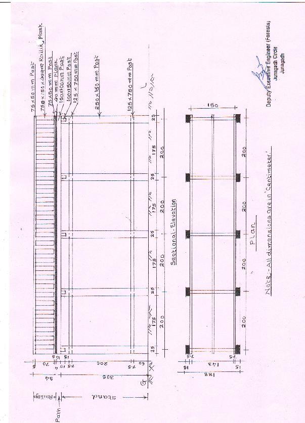
192 Page 191
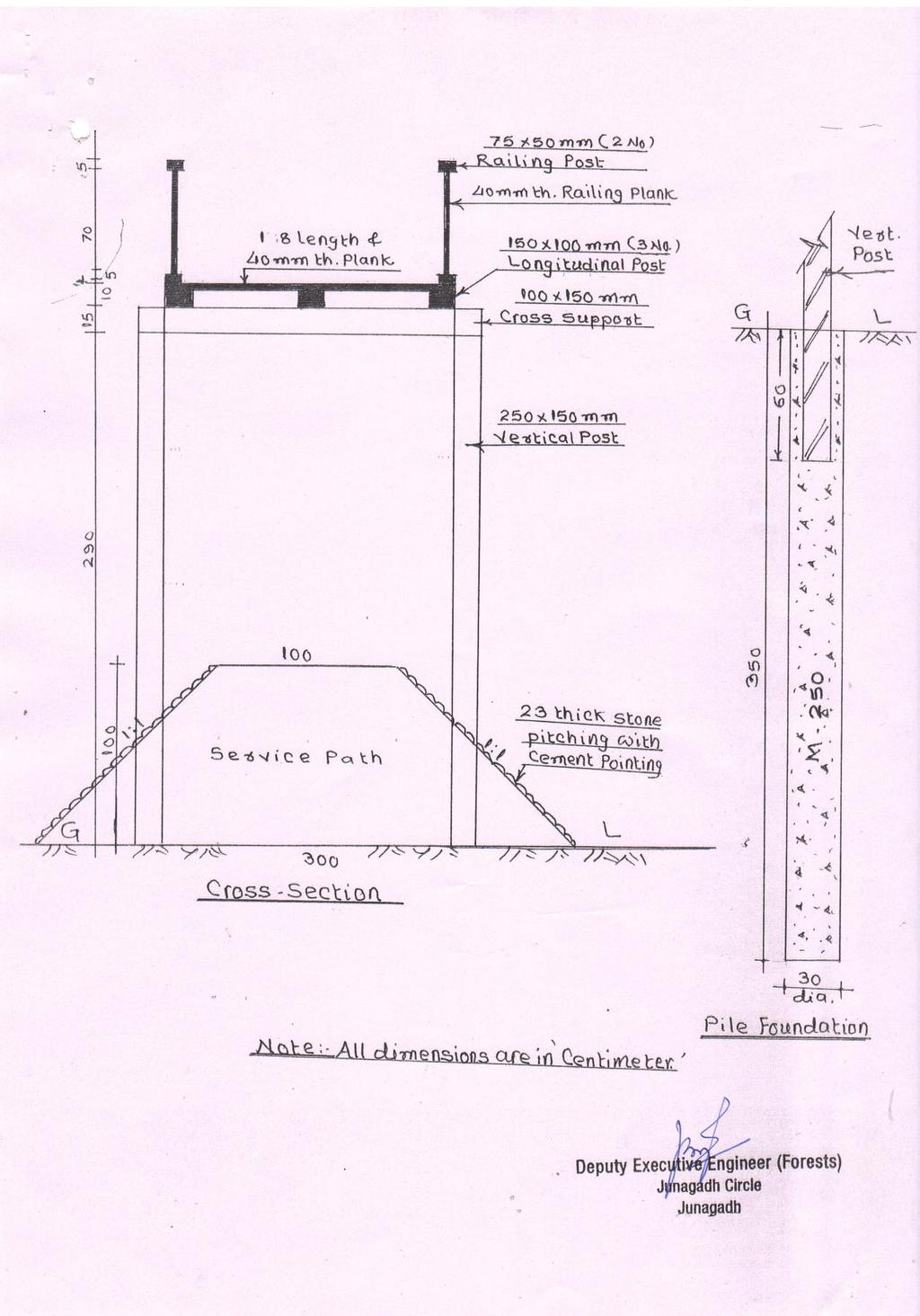
193 Page 192
BID DOCUMENT. Renovation of Hukitola Building at Hukitola Dist:Kendrapara. (Package No.- ICZM/W/WL/16/ ] ON BEHALF OF
![BID DOCUMENT. Renovation of Hukitola Building at Hukitola Dist:Kendrapara. (Package No.- ICZM/W/WL/16/ ] ON BEHALF OF](/thumbs/74/70708520.jpg "BID DOCUMENT. Renovation of Hukitola Building at Hukitola Dist:Kendrapara. (Package No.- ICZM/W/WL/16/ ] ON BEHALF OF") BID DOCUMENT INTEGRATED COASTAL ZONE MANAGEMENT PROJECT STATE PROJECT MANAGEMENT UNIT ODISHA Renovation of Hukitola Building at Hukitola Dist:Kendrapara (Package No.- ICZM/W/WL/16/2013-14] 2013 14 ON BEHALF
BID DOCUMENT INTEGRATED COASTAL ZONE MANAGEMENT PROJECT STATE PROJECT MANAGEMENT UNIT ODISHA Renovation of Hukitola Building at Hukitola Dist:Kendrapara (Package No.- ICZM/W/WL/16/2013-14] 2013 14 ON BEHALF
ASIAN UNIVERSITY FOR WOMEN PROCUREMENT OF CONSTRUCTION OF CAMPUS CENTER & AUDITORIUM BUILDING OF ASIAN UNIVERSITY FOR WOMEN AT PAHARTOLI, CHITTAGONG
 ii ASIAN UNIVERSITY FOR WOMEN ASIAN UNIVERSITY FOR WOMEN CAMPUS PROJECT PROCUREMENT DOCUMENTS PREQUALIFICATION DOCUMENTS FOR PROCUREMENT OF CONSTRUCTION OF CAMPUS CENTER & AUDITORIUM BUILDING OF ASIAN
Invitation for Bids. Deadline for Submission of Bids: July 17, 2017 up to 1200 Hours (Nepal Standard Time)
") Invitation for Bids Grant No. and Title: 2015 68 112: Reconstruction and Improvement of Electricity in Earthquake Affected Districts. Tender No. and Title: ICB-REIP-073/74-01, Lot 1: Immediate Relief Measure
Invitation for Bids Grant No. and Title: 2015 68 112: Reconstruction and Improvement of Electricity in Earthquake Affected Districts. Tender No. and Title: ICB-REIP-073/74-01, Lot 1: Immediate Relief Measure
Tender Document Fees in Rs. Date of Issue of Tender Document 1000/- 25/09/ /10/2015
 INDIAN INSTITUTE OF TROPICAL METEOROLOGY ( IITM) PASHAN, PUNE-411 008 e-tender NOTICE Director, Indian Institute of Tropical Meteorology, Dr. Homi Bhabha Road, Pashan, Pune-411 008, (India). Invites sealed
BIDDING DOCUMENTS (PROCUREMENT OF GOOD AND SERVICES)
") BIDDING DOCUMENTS (PROCUREMENT OF GOOD AND SERVICES) IOM Nigeria FRAMEWORK AGREEMENT FOR SUPPLY OF DIESEL FOR ONE (1) YEAR ITB NO: NG10-014 Prepared by DORCAS SHAIBU 11 January, 2018 IOM Nigeria No.11
BIDDING DOCUMENTS (PROCUREMENT OF GOOD AND SERVICES) IOM Nigeria FRAMEWORK AGREEMENT FOR SUPPLY OF DIESEL FOR ONE (1) YEAR ITB NO: NG10-014 Prepared by DORCAS SHAIBU 11 January, 2018 IOM Nigeria No.11
Procurement of Goods
 GOVERNMENT OF MEGHALAYA SUPPORTING HUMAN CAPITAL DEVELOPMENT IN MEGHALAYA (SHCDM) (ADB LOAN NO. 3033-IND) Bid Document for Phase-I Procurement of Lab/Workshop, Classroom, Library and IT Lab equipment,
Proposed Building and Civil Engineering Workshops for Machakos University College - Phase II
 MACHAKOS UNIVERSITY COLLEGE ISO 9001:2008 Certified (A Constituent College of Kenyatta University TENDER DOCUMENT FOR THE PROPOSED CONSTRUCTION AND COMPLETION OF BUILDING AND CIVIL ENGINEERING WORKSHOPS
MINISTRY OF TRANSPORT, ROADS, PUBLIC WORKS AND HOUSING
 COUNTY GOVERNMENT OF MACHAKOS MINISTRY OF TRANSPORT, ROADS, PUBLIC WORKS AND HOUSING PROPOSED CONSTRUCTION OF COUNTY GOVERNMENT OFFICES AT MATUU-MACHAKOS COUNTY TENDER DOCUMENTS QUANTITY SURVEYOR PUBLIC
REPUBLIC OF KENYA COUNTY GOVERNMENT OF TURKANA PROPOSED CONSTRUCTION OF 3 BEDROOMED STAFF HOUSE BLOCKS
 REPUBLIC OF KENYA COUNTY GOVERNMENT OF TURKANA PROPOSED CONSTRUCTION OF 3 BEDROOMED STAFF HOUSE BLOCKS AT ELELEA SUBCOUNTY HOSPITAL IN ELELEA WARD, TURKANA COUNTY BILLS OF QUANTITIES Tender No... County
B I D D I N G D O C U M E N T S
 REPUBLIC OF KENYA MINISTRY OF WATER AND IRRIGATION STATE DEPARTMENT OF WATER TANATHI WATER SERVICES BOARD FUNDING DESIGN AND BUILD OF NDARUGU 1 DAM WATER SUPPLY PROJECT B I D D I N G D O C U M E N T S
MINISTRY OF HEALTH & FAMILY WELFARE National AIDS Control Organization (NACO) Government of India. National AIDS Control Programme Phase-IV (NACP-IV)
 Government of India. National AIDS Control Programme Phase-IV (NACP-IV)") 1 MINISTRY OF HEALTH & FAMILY WELFARE National AIDS Control Organization (NACO) Government of India National AIDS Control Programme Phase-IV (NACP-IV) NATIONAL COMPETITIVE BIDDING BID DOCUMENT For PROCUREMENT
1 MINISTRY OF HEALTH & FAMILY WELFARE National AIDS Control Organization (NACO) Government of India National AIDS Control Programme Phase-IV (NACP-IV) NATIONAL COMPETITIVE BIDDING BID DOCUMENT For PROCUREMENT
KENYA ELECTRICITY GENERATING COMPANY LIMITED KGN-GDD
 KENYA ELECTRICITY GENERATING COMPANY LIMITED KGN-GDD-070-2018 TENDER FOR STRUCTURAL REHABILITATION OF OLKARIA II GEOTHERMAL POWER STATION (OPEN NATIONAL) Kenya Electricity Generating Company Limited Stima
INDIAN INSTITUTE OF TROPICAL METEOROLOGY PASHAN, PUNE Tender No. CE/IITM/Project/Conf./Interior/ /02 e-tender NOTICE
 INDIAN INSTITUTE OF TROPICAL METEOROLOGY PASHAN, PUNE-411 008 Tender No. CE/IITM/Project/Conf./Interior/2012-13/02 e-tender NOTICE Director, Indian Institute of Tropical Meteorology, Dr. Homi Bhabha Road,
NAIROBI CITY COUNTY TENDER NO.NCC /WATER/WDF/RT/168/2016/2017 PROPOSED CONSTRUCTION OF TOILETS BLOCK WITH ROOF SPACE HALL AT LAND MAWE WARD.
 NAIROBI CITY COUNTY Telephone: 020 344194 web: www.nairobi.go.ke City Hall, P. O. Box 30075-00100, Nairobi, KENYA. TENDER NO.NCC /WATER/WDF/RT/168/2016/2017 PROPOSED CONSTRUCTION OF TOILETS BLOCK WITH
REGISTRATION FOR SUPPLY, DELIVERY, INSTALLATION, REPAIR AND MAINTENANCE OF AIR CONDITIONERS SERVICE PROVIDERS
 UNIVERSITY OF EMBU REGISTRATION FOR SUPPLY, DELIVERY, INSTALLATION, REPAIR AND MAINTENANCE OF AIR CONDITIONERS SERVICE PROVIDERS UoEm/04/2017-2019 CLOSING DATE: APRIL 18TH 2017 AT 11.00 AM Table of Contents
PROPOSED ERECTION AND COMPLETION OF LAND REGISTRY AND OFFICES BLOCK AT KWALE TOWN, KWALE COUNTY W.P. ITEM NO. D111 CO / KWL/ 1501 JOB NO.
 REPUBLIC OF KENYA MINISTRY OF LAND, HOUSING AND URBAN DEVELOPMENT STATE DEPARTMENT OF LAND PROPOSED ERECTION AND COMPLETION OF LAND REGISTRY AND OFFICES BLOCK AT KWALE TOWN, KWALE COUNTY W.P. ITEM NO.
BIDDING DOCUMENT. Contract No. PAL 3060/61-KASP-Works ICB-03 VOLUME 1
 REPUBLIC OF PALAU PALAU PUBLIC UTILITIES CORPORATION (PPUC) KOROR-AIRAI SANITATION PROJECT (KASP) BIDDING DOCUMENT Sewage Treatment Plant Upgrade in Malakal Contract No. PAL 3060/61-KASP-Works ICB-03 VOLUME
A F R I C A N U N I O N Standard Bidding Document
 A F R I C A N U N I O N Standard Bidding Document Procurement of Goods and Services Open Tender REGIONAL COMPETITIVE BIDDING (RCB) African Peer Review Mechanism Procurement Number: 2/APRM/IT/07/17 TENDER
REPUBLIC OF KENYA RIFT VALLEY WATER SERVICE BOARD TULWOPSOO-LONTRIM WATER SUPPLY (PRIORITY FUND PROGRAMME) TENDER No: RVWSB// TUL-LON /PPP /
 TENDER No: RVWSB// TUL-LON /PPP /") REPUBLIC OF KENYA RIFT VALLEY WATER SERVICES BOARD TULWOPSOO-LONTRIM WATER SUPPLY (PRIORITY FUND PROGRAMME) TENDER No: RVWSB// TUL-LON /PPP /2016-2017 TENDER DOCUMENT EMPLOYER PROJECT MANAGER RIFT VALLEY
REPUBLIC OF KENYA RIFT VALLEY WATER SERVICES BOARD TULWOPSOO-LONTRIM WATER SUPPLY (PRIORITY FUND PROGRAMME) TENDER No: RVWSB// TUL-LON /PPP /2016-2017 TENDER DOCUMENT EMPLOYER PROJECT MANAGER RIFT VALLEY
India Tender. Construction - I VOLUME
 8th Floor, Block No. 18, Udyog Bhavan, Sector-11, Gandhinagar, Gujarat, India-382017. Tel :+91-79-23232701/4 Fax : +91-79-23222481 email: garud.gandhinagar@gmail.com ====== ========= ========== =========
REPUBLIC OF KENYA MINISTRY OF HEALTH (NATIONAL PUBLIC HEALTH LABORATORY SERVICES)
") REPUBLIC OF KENYA MINISTRY OF HEALTH (NATIONAL PUBLIC HEALTH LABORATORY SERVICES) TENDER DOCUMENT FOR CONSTRUCTION OF BIOSAFETY LEVEL II LABORATORY (BSL II) (PUBLIC HEALTH LABORATORY) AT MOI TEACHING REFERRAL
REPUBLIC OF KENYA MINISTRY OF HEALTH (NATIONAL PUBLIC HEALTH LABORATORY SERVICES) TENDER DOCUMENT FOR CONSTRUCTION OF BIOSAFETY LEVEL II LABORATORY (BSL II) (PUBLIC HEALTH LABORATORY) AT MOI TEACHING REFERRAL
National Science Foundation Ministry of Science, Technology & Research
 1 National Science Foundation Ministry of Science, Technology & Research BIDDING DOCUMENT PROCUREMENT OF IBM SPSS STASTICAL SOFT WARE NATIONAL COMPETITIVE BIDDING Minimum Specifications requested by NSF
Bidding Conditions. March 22, (Project# 0192) at the. Fresno Chaffee Zoo. Project : Warthog Exhibit. Located at. 894 West Belmont Avenue
 at the. Fresno Chaffee Zoo. Project : Warthog Exhibit. Located at. 894 West Belmont Avenue") Bidding Conditions March 22, 2018 (Project# 0192) at the Fresno Chaffee Zoo Project : Warthog Exhibit Located at 894 West Belmont Avenue Fresno, CA 93728 Page 1 of 8 DEFINITIONS Addendum - A document issued
Bidding Conditions March 22, 2018 (Project# 0192) at the Fresno Chaffee Zoo Project : Warthog Exhibit Located at 894 West Belmont Avenue Fresno, CA 93728 Page 1 of 8 DEFINITIONS Addendum - A document issued
Open National Tender (ONT) Tender Document. For the. SUPPLY OF NON-PHARMACEUTICALS (Surgical sutures, Dispensing envelopes)
 Tender Document. For the. SUPPLY OF NON-PHARMACEUTICALS (Surgical sutures, Dispensing envelopes)") Open National Tender (ONT) Tender Document For the SUPPLY OF NON-PHARMACEUTICALS (Surgical sutures, Dispensing envelopes) Invitation for Tender (IFT) Number: KEMSA/ONT 04/2017-2019 FRAMEWORK CONTRACTING
Open National Tender (ONT) Tender Document For the SUPPLY OF NON-PHARMACEUTICALS (Surgical sutures, Dispensing envelopes) Invitation for Tender (IFT) Number: KEMSA/ONT 04/2017-2019 FRAMEWORK CONTRACTING
KENYA ELECTRICITY GENERATING COMPANY LIMITED KGN-GT
 KENYA ELECTRICITY GENERATING COMPANY LIMITED KGN-GT-012-2017 Tender for Re-location of One GE Frame 6 Gas Turbine Plant from Embakasi in Nairobi to Muhoroni near Kisumu. Scope :( Dismantling, Transportation,
REPUBLIC OF KENYA COUNTY GOVERNMENT OF KIRINYAGA
 REPUBLIC OF KENYA COUNTY GOVERNMENT OF KIRINYAGA NOMINATED SUB-CONTRACT TENDER DOCUMENT FOR THE PROPOSED MEDICAL COMPLEX - PHASE 1 AT KERUGOYA COUNTY HOSPITAL IN KERUGOYA TOWN, KIRINYAGA COUNTY ERECTION
Open International Tender (OIT) Government of Kenya, Ministry of Health Nairobi/Kenya. Tender Document. For the
 Government of Kenya, Ministry of Health Nairobi/Kenya. Tender Document. For the") Open International Tender (OIT) Government of Kenya, Ministry of Health Nairobi/Kenya Tender Document For the Supply and delivery of Mobile Digital X - Ray Machines ITT No.: GF ATM TB NFM - 17/18 OIT -
Open International Tender (OIT) Government of Kenya, Ministry of Health Nairobi/Kenya Tender Document For the Supply and delivery of Mobile Digital X - Ray Machines ITT No.: GF ATM TB NFM - 17/18 OIT -
TEACHERS SERVICE COMMISSION TENDER DOCUMENT FOR DISPOSAL OF LPG CYLINDERS WITH GAS (TSC EMPLOYEES ONLY). CLOSING DATE: FRIDAY, 1 ST APRIL 2016.
. CLOSING DATE: FRIDAY, 1 ST APRIL 2016.") TEACHERS SERVICE COMMISSION TENDER DOCUMENT FOR DISPOSAL OF LPG CYLINDERS WITH GAS (TSC EMPLOYEES ONLY). TENDER NUMBER: TSC/DISP/02/2015-2016 CLOSING DATE: FRIDAY, 1 ST APRIL 2016. Teachers Service Commission
TEACHERS SERVICE COMMISSION TENDER DOCUMENT FOR DISPOSAL OF LPG CYLINDERS WITH GAS (TSC EMPLOYEES ONLY). TENDER NUMBER: TSC/DISP/02/2015-2016 CLOSING DATE: FRIDAY, 1 ST APRIL 2016. Teachers Service Commission
Bidding Conditions Attachment C
 Bidding Conditions Attachment C REV Date: November 9, 2018 Project Name (Permit Nos. xxx) at the Fresno Chaffee Zoo Project No. xxxx Located at 894 West Belmont Avenue Fresno, CA 93728 Page 1 of 8 DEFINITIONS
Section IV. Bidding Forms
 Section IV. Bidding Forms 1-1 Section IV. Bidding Forms Table of Forms Letter of Bid... 3 Form of Bid Security (Bank Guarantee)... 6 Form of Bid Security (Bid Bond)... 7 Form of Bid-Securing Declaration...
I n t e r n a t i o n a l C o m p e t i tiv e B i d d i n g D o c u m e n t
 R E P U B L I C O F L I B E R I A N A T I O N A L E L E C T I O N S C O M M I S S I O N B i d d i n g D o c u m e n t I n t e r n a t i o n a l C o m p e t i tiv e B i d d i n g D o c u m e n t F o r t
AFRICAN UNION COMMISSION PROCUREMENT OF GOODS BY OPEN TENDER SUPPLY AND DELIVERY OF MEDICAL EQUIPMENTS
 AFRICAN UNION UNION AFRICAINE UNIÃO AFRICANA Addis Ababa, ETHIOPIA P. O. Box 3243 Tel: +25 (0)-55 7700 Fax: +25 (0)-55 0430 Website : www.africa-union.org AFRICAN UNION COMMISSION PROCUREMENT OF GOODS
PRE-QUALIFICATION FOR PROVISION OF TEAM BUILDING CONSULTANCY SERVICES TENDER NO. KPPF /HRA-B/1-A/22/17-18
 PRE-QUALIFICATION FOR PROVISION OF TEAM BUILDING CONSULTANCY SERVICES TENDER NO. KPPF /HRA-B/1-A/22/17-18 (JAN 2017 DEC 2018) PRE QUALIFICATION DOCUMENT Stima Plaza, Kolobot Road, P.O. Box 1548-00600 Nairobi,
REPUBLIC OF KENYA COUNTY GOVERNMENT OF NYANDARUA
 REPUBLIC OF KENYA COUNTY GOVERNMENT OF NYANDARUA DEPARTMENT OF ROADS, PUBLIC WORKS & TRANSPORT PROPOSED COSTRUCTION AND COMPLETION OF TYPE DISPENSARIES & ASSOCIATED EXTERNAL WORKS FOR THE MIN. OF HEALTH
MADHYA PRADESH GOVERNMENT Madhya Pradesh Forest Department Satpura Bhawan, Bhopal (M.P.) EXPRESSION OF INTEREST (EOI)
 EXPRESSION OF INTEREST (EOI)") MADHYA PRADESH GOVERNMENT Madhya Pradesh Forest Department Satpura Bhawan, Bhopal (M.P.)-462003 EXPRESSION OF INTEREST (EOI) Notice Inviting Expression of Interest (EOI) for hiring the services of consultants
MADHYA PRADESH GOVERNMENT Madhya Pradesh Forest Department Satpura Bhawan, Bhopal (M.P.)-462003 EXPRESSION OF INTEREST (EOI) Notice Inviting Expression of Interest (EOI) for hiring the services of consultants
BIDDING DOCUMENT FOR PROCUREMENT OF CONSULTANCY WORK
 BIDDING DOCUMENT FOR PROCUREMENT OF CONSULTANCY WORK 1 PIMPRI-CHINCHWAD NEW TOWN DEVLOPMENT AUTHORITY NIGDI, PUNE 411 044 Tender inviting for appointment of consultants for preparing GAD and Junction Design
PREQUALIFICATION DOCUMENT FOR SUPPLY OF DISPENSERS, DRINKING WATER AND DISPOSABLE - TENDER NO KENAS NO/28/2013/2015
 PREQUALIFICATION DOCUMENT FOR SUPPLY OF DISPENSERS, DRINKING WATER AND DISPOSABLE - TENDER NO KENAS NO/28/2013/201 KENYA ACCREDITATION SERVICE P.O BOX 47400-00100 NAIROBI KENYA Tel: 0787 39 679 or 072
Tender for the installation and construction of Mwalija Solar Powered Irrigation Scheme in Chikwawa District: Publication reference: MWI
 Tender for the installation and construction of Mwalija Solar Powered Irrigation Scheme in Chikwawa District: Publication reference: MWI 1014 18-04 G O V E R N M E N T O F M A L A W I REPRESENTED BY THE
Bangalore International Airport Limited INFORMATION DOCUMENT REQUEST FOR PROPOSAL (RFP) For
 For") Bangalore International Airport Limited INFORMATION DOCUMENT ON REQUEST FOR PROPOSAL (RFP) For ENGAGING DESIGN CONSULTANT TO PROVIDE DESIGN SERVICES FOR INTERIM TERMINAL1 (T1) IMPROVEMENTS (SWEAT) AT KEMPEGOWDA
Bangalore International Airport Limited INFORMATION DOCUMENT ON REQUEST FOR PROPOSAL (RFP) For ENGAGING DESIGN CONSULTANT TO PROVIDE DESIGN SERVICES FOR INTERIM TERMINAL1 (T1) IMPROVEMENTS (SWEAT) AT KEMPEGOWDA
NAIROBI CITY COUNTY BID DOCUMENT FOR INSTALLATION OF LIGHTS AT PELICAN CROSSING POINTS ON SELECTED LOCATIONS WITHIN THE CBD
 NAIROBI CITY COUNTY BID DOCUMENT FOR INSTALLATION OF LIGHTS AT PELICAN CROSSING POINTS ON SELECTED LOCATIONS WITHIN THE CBD TENDER No. NCC/T/RPW&T/205/2017- Chief officer Roads, Public works and Transport
Tamil Nadu Road Development Company Ltd.
 Tamil Nadu Road Development Company Ltd. (TNRDC) Widening of East Coast Road (ECR) from Double Lane into Four Lane from KM 22/300 to KM 55/800, Including Improvement to Curved Stretches 13 Nos & Junctions-7
Tender for Engagement of Chartered Accountant CONTENTS
 Date Sri Aurobindo Marg, New Delhi 110016 Bidding/TENDER DOCUMENT Tender for Engagement of Chartered Accountant CONTENTS Page Contents no. 1-2 Invitation for bid 3 Procedures for submission of bid 3 Amendment
Supply of Office Furniture, Fittings, Furnishings & other Equipments.
 The Kenya Power & Lighting Co. Ltd. The Kenya Power & Lighting Co. Ltd. Central Office P.O. Box 30099 Nairobi, Kenya Telephone 254-02-3201 000/3201 323 Fax No. 254-02-310336 or 3753833 Website: www.kplc.co.ke
ETHICS AND ANTI-CORRUPTION COMMISSION
 ETHICS AND ANTI-CORRUPTION COMMISSION TENDER DOCUMENT FOR PROPOSED OFFICE PARTITIONING AND REFURBISHMENT TO ETHICS AND ANTI- CORRUPTION COMMISSION OFFICES ON 1ST FLOOR, CENTRAL SQUARE BUILDING, KISUMU
PRE-QUALIFICATION OF SUPPLIERS PROVISION OF FUMIGATION, SANITATION AND SANITAL DISPOSAL SERVICES TENDER NO.KPLC1/5BC/9A/PT-ST/113/2010
 The Kenya Power & Lighting Co. Ltd. The Kenya Power & Lighting Co. Ltd. Central Office P.O. Box 30099 Nairobi, Kenya Telephone 254-02-3201 000/3201 323 Fax No. 254-02-310336 or 3753833 Website: www.kplc.co.ke
Tender No GSO/CED/CE/TR - 410/2011
 Government of India Department of Atomic Energy General Services Organisation Civil Engineering Division Tender No GSO/CED/CE/TR - 410/2011 Sealed item rate tenders in TWO Parts in the prescribed forms
INVITATION FOR PREQUALIFICATION FOR THE CONSTRUCTION OF WORKS
 INVITATION FOR PREQUALIFICATION FOR THE CONSTRUCTION OF WORKS Title: 530 and 531 KOS 4000 restoration of wall paintings of Bogorodica Ljeviska Church in Prizren Safeguard of Cultural Page 1 of 24 INVITATION
TENDER SUPPLY, INSTALLATION, TESTING AND COMMISSIONING OF CCTV SURVEILLANCE AND ACCESS CONTROL SYSTEM
 THE KENYATTA INTERNATIONAL CONVENTION CENTRE TENDER SUPPLY, INSTALLATION, TESTING AND COMMISSIONING OF CCTV SURVEILLANCE AND ACCESS CONTROL SYSTEM KENYATTA INTERNATIONAL CONVENTION CENTRE KICCBUILDING
International Peace Support Training Centre Westwood Park P O Box Karen, Kenya
 International Peace Support Training Centre Westwood Park P O Box 24232-00502 Karen, Kenya PRE-QUALIFICATION TENDER NO.IPSTC/PREQ/2016/2017/231FOR REGISTRATION OF SUPPLIERS FOR PROVISION OF TENTS CHAIRS
PROPOSED STORAGE FACILITIES AND COMMERCIAL OFFICES AT ELDORET
 PROPOSED STORAGE FACILITIES AND COMMERCIAL OFFICES AT ELDORET SPECIFICATIONS AND BILLS OF QUANTITIES FOR ELECTRICAL INSTALLATION CLIENT Kenya Power and Lighting Co. Ltd. P. O. Box 30099-00100 NAIROBI ARCHITECT:
SIMLAW Seed CoMpAny LIMIted
 SIMLAW Seed CoMpAny LIMIted TENDER DOCUMENT TENDER FOR SALE OF BOARDED MOTOR VEHICLES AND BEANS TENDER REF: SSC/T/DC/10/2018/2019 TENDER CLOSING & OPENING DATE: -16 th NOVEMBER, 2018 SIMLAW SEED COMPANY
INDIAN INSTITUTE OF TECHNOLOGY INDORE
 INDIAN INSTITUTE OF TECHNOLOGY INDORE Notice Inviting Tender 1. Item rate tenders are invited from eligible contractors registered/enlisted with Central Government Departments/State Government Departments/
Disable friendly Washrooms at hostel blocks (A & E)
") Telephone: 080-26993580 080-26993360 Fax:080- :26584050 Email: anil.sj@iimb.ernet.in : shivakumar.k@iimb.ernet.in TENDER NOTICE: 16 th February 2015 E.M.D (Rs.) TO BE SUBMITTED ALONG WITH TENDER Tender
Telephone: 080-26993580 080-26993360 Fax:080- :26584050 Email: anil.sj@iimb.ernet.in : shivakumar.k@iimb.ernet.in TENDER NOTICE: 16 th February 2015 E.M.D (Rs.) TO BE SUBMITTED ALONG WITH TENDER Tender
SECTION I: ADVERTISEMENT/ INVITATION TO TENDER... 3 DISPOSAL NOTICE... 3 CONDITION OF SALE... 3 TENDERING INSTRUCTIONS... 3
 TABLE OF CONTENTS SECTION I: ADVERTISEMENT/ INVITATION TO TENDER... 3 DISPOSAL NOTICE... 3 CONDITION OF SALE... 3 TENDERING INSTRUCTIONS... 3 SECTION II- INSTRUCTIONS TO TENDERER... 4 ELIGIBILITY... 4
PRE-QUALIFICATION DOCUMENT FOR SUPPLY AND DELIVERY OF STAFF UNIFORMS, SPORTS GEAR AND SHOES MAY 2015 CHIEF EXECUTIVE OFFICER ATHI WATER SERVICES BOARD
 PRE-QUALIFICATION DOCUMENT FOR SUPPLY AND DELIVERY OF STAFF UNIFORMS, SPORTS GEAR AND SHOES CONTRACT NO: AWSB/HQ/PQ/09/2015-2017 MAY 2015 CHIEF EXECUTIVE OFFICER ATHI WATER SERVICES BOARD P.O BOX 45283-00100
TENDER FOR SUPPLY OF OFFICE FURNITURE (RESERVED FOR THE SPECIAL GROUPS)
") GEOTHERMAL DEVELOPMENT COMPANY LIMITED GDC/PM/OT/016/2016-2017 TENDER FOR SUPPLY OF OFFICE FURNITURE (RESERVED FOR THE SPECIAL GROUPS) CLOSING DATE AND TIME: 17th October, 2016 at 2.00Pm Geothermal Development
GEOTHERMAL DEVELOPMENT COMPANY LIMITED GDC/PM/OT/016/2016-2017 TENDER FOR SUPPLY OF OFFICE FURNITURE (RESERVED FOR THE SPECIAL GROUPS) CLOSING DATE AND TIME: 17th October, 2016 at 2.00Pm Geothermal Development
ROADS AND FLEET MANAGEMENT DEPARTMENT
 ROADS AND FLEET MANAGEMENT DEPARTMENT TENDER NO. KWS/OT/R&F/22/2017 2018 ROUTINE MAINTENANCE OF JUNCT A109 CHYULU HILLS ROAD(E1819) IN CHYULU NATIONAL PARK February 2018 (Persons With Disability) HEAD,
CIVIL DEPARTMENT. Name of the Work-RW: - GI Chainlink fencing. Name of the Bidder: - Address: - Phone No.: - Mobile: - -
 Rs. 500.00/- CIVIL DEPARTMENT Name of the Work-RW: - GI Chainlink fencing Name of the Bidder: - Address: - Phone No.: - Mobile: - Email: - (Employer) Invitation of tenders for GI Chainlink fencing Ref.
UNIVERSAL SERVICE FUND CO (USF) Request for Application PREQUALIFICATION OF INSTITUTES FOR THE BOARD OF DIRECTORS ORIENTATION AND LEARNING PROGRAMME
 Request for Application PREQUALIFICATION OF INSTITUTES FOR THE BOARD OF DIRECTORS ORIENTATION AND LEARNING PROGRAMME") UNIVERSAL SERVICE FUND CO (USF) Request for Application PREQUALIFICATION OF INSTITUTES FOR THE BOARD OF DIRECTORS ORIENTATION AND LEARNING PROGRAMME December, 2016 (TENDER DOCUMENT FOR PREQUALIFICATION
UNIVERSAL SERVICE FUND CO (USF) Request for Application PREQUALIFICATION OF INSTITUTES FOR THE BOARD OF DIRECTORS ORIENTATION AND LEARNING PROGRAMME December, 2016 (TENDER DOCUMENT FOR PREQUALIFICATION
CHIEF EXECUTIVE OFFICER ATHI WATER SERVICES BOARD P.O BOX NAIROBI
 PRE-QUALIFICATION DOCUMENT FOR PROVISION OF CREATIVE DESIGN, LAYOUT AND PRINTING OF MAGAZINES, CALENDARS, PROMOTIONAL MATERIALS, BROCHURES, NOTEBOOKS AND DIARIES CONTRACT NO: AWSB/HQ/PQ/18/2015-2017 MAY
INSTRUCTIONS TO BIDDERS
 INSTRUCTIONS TO BIDDERS CONTENTS I. Bid Documents II. Ethical Business Practices III. Contractor Qualifications IV. Performance and Quality Standards V. Bid Evaluation VI. Contract Award VII. Work Operations
NATIONAL INDUSTRIAL TRAINING AUTHORITY TENDER NO.NITA/26/
 NATIONAL INDUSTRIAL TRAINING AUTHORITY TENDER NO.NITA/26/2016-2017 TENDER FOR SUPPLY, DELIVERY, INSTALLATION, CONFIGURATION AND COMMISIONING OF A STRUCTURED CABLING LOCAL AREA NETWORK, FIBER EXTENSION
The Kenya Power & Lighting Co. Ltd.
 The Kenya Power & Lighting Co. Ltd. TENDER NO. KPLC1/6D/PT/D/02/11 SUPPLY, INSTALLATION AND COMMISSIONING OF ADDITIONAL FEEDER BREAKER AND 1MVA STEP- UP TRANSFORMER AT MANDERA AND LODWAR POWER STATIONS
Supply of 220/132/11 kv, 200 MVA & 160 MVA, Auto Transformers and Related Services for Sarusajai & Salekathi Grid Substations in Assam
 BIDDING DOCUMENT FOR Supply of 220/132/11 kv, 200 MVA & 160 MVA, Auto Transformers and Related Services for Sarusajai & Salekathi Grid Substations in Assam BID IDENTIFICATION NO:-AEGCL/MD/TECH-652/ /200,
Government of Sindh. SINDH REVENUE BOARD Shaheen Complex Building, 6 th Floor, M.R Kiyani Road, Karachi-Pakistan Bidding Document.
 Government of Sindh de SINDH REVENUE BOARD Shaheen Complex Building, 6 th Floor, M.R Kiyani Road, Karachi-Pakistan www.srb.gos.pk Bidding Document For Supply of Online Fiscal Point of Sale Integration
Supply of 40 MVA, 132/33 kv Power Transformers and Related Services for Srikona and Sipajhar Grid Substations in Assam
 BIDDING DOCUMENT FOR Supply of 40 MVA, 132/33 kv Power Transformers and Related Services for Srikona and Sipajhar Grid Substations in Assam A S S A M E L E C T R I C I T Y G R I D C O R P O R A T I O N
COUNTY GOVERNMENT OF NYERI
 COUNTY GOVERNMENT OF NYERI WHEN REPLYING PLEASE QUOTE OUR REFERENCE NO AND DATE. ALL CORRESPONDENCES TO BE ADDRESSED TO THE COUNTY SECRETARY OR THE CHIEF OFFICERS OF DEPARTMENTS P.o. Box 1112-10100 NYERI
Deadline for documents submission June 11, 2009 before 12:00 hours (local time)
") United Nations Development Programme Date: 26 May 2009 Expression of Interest Pre-Qualification for Civil Works Ref: PRQ/KRT/09/001- R1 United Nations Development Programme (UNDP), Sudan office announces
United Nations Development Programme Date: 26 May 2009 Expression of Interest Pre-Qualification for Civil Works Ref: PRQ/KRT/09/001- R1 United Nations Development Programme (UNDP), Sudan office announces
JUNE 2017 CHIEF EXECUTIVE OFFICER TANATHI WATER SERVICES BOARD KIDP BUILDING, KALAWA ROAD PRIVATE BAG KITUI
 TANATHI WATER SERVICES BOARD K.I.D.P. Bldg., Kalawa Rd., Private Bag, Kitui. Phone: 020 8009628/044-4422416 Telefax: +254 044-44221O8/4422417 Email: tanathiwsb@gmail.com PRE-QUALIFICATION DOCUMENT FOR
PREQUALIFICATION DOCUMENTS. for. Procurement of
 PREQUALIFICATION DOCUMENTS for Procurement of Design, manufacture, supply, installation, testing and commissioning of Rolling Stock Employer: Mumbai Metro Rail Corporation Country: Republic of India Project:
Design and Build of Passenger Terminal Building North Extension At Macau International Airport (RFQ-198) Section 1 Instruction to Bidders
 Section 1 Instruction to Bidders") At Macau International Airport (RFQ-198) Section 1 Instruction to Bidders Table of Contents Page S.1/ Section 1 - Instruction to Bidders ( ITB )... 3 1. Introduction... 3 2. Eligibility of Bidders... 3
At Macau International Airport (RFQ-198) Section 1 Instruction to Bidders Table of Contents Page S.1/ Section 1 - Instruction to Bidders ( ITB )... 3 1. Introduction... 3 2. Eligibility of Bidders... 3
KARATINA UNIVERSITY PROPOSED LIBRARY
 KARATINA UNIVERSITY PROPOSED LIBRARY TENDER NAME: PLUMBING AND DRAINAGE SUB-CONTRACT BILL OF QUANTITIES (Re-tender) TENDER NUMBER: KarU/OT/05/LIB/2017-2018 Project Consultants: JKUATES LTD P.O. BOX 62000-00200
BIDDING INVITATION RELATING TO ACMI LEASE OF AIRCRAFT AOAFF N 06/2018/AH-DP. Attention of Bidders is drawn to the following:
 BIDDING INVITATION RELATING TO ACMI LEASE OF AIRCRAFT Attention of Bidders is drawn to the following: Aircrafts are required on ACMI Lease To operate AIR ALGERIE regular schedule and Hadj flights as per
TAMILNADU MEDICAL SERVICES CORPORATION LIMITED 417 Pantheon Road, Egmore, Chennai - 8 Website: tnmsc.
 TAMILNADU MEDICAL SERVICES CORPORATION LIMITED 417 Pantheon Road, Egmore, Chennai - 8 Website: www.tnmsc.com E-mail: enquiry @ tnmsc.com BID REFERENCE:325/CSSD/PMSSY-GRHM/TNMSC/ENGG/2018, DT:03.05.2018
REPUBLIC OF KENYA RIFT VALLEY WATER SERVICE BOARD MILIMA TATU WATER SUPPLY PROJECT (PRIORITY PROJECTS PROGRAMME) TENDER No:
 TENDER No:") REPUBLIC OF KENYA RIFT VALLEY WATER SERVICES BOARD MILIMA TATU WATER SUPPLY PROJECT (PRIORITY PROJECTS PROGRAMME) TENDER No: RVWSB/MLM-TAT/EQ /2017-2018 TENDER DOCUMENT EMPLOYER PROJECT MANAGER RIFT VALLEY
REPUBLIC OF KENYA RIFT VALLEY WATER SERVICES BOARD MILIMA TATU WATER SUPPLY PROJECT (PRIORITY PROJECTS PROGRAMME) TENDER No: RVWSB/MLM-TAT/EQ /2017-2018 TENDER DOCUMENT EMPLOYER PROJECT MANAGER RIFT VALLEY
PRE-BID MEETING VENUE : CONFERENCE HALL ANDHRA PRADESH FOODS, ROAD No. 14, IDA, NACHARAM HYDERABAD ANDHRA PRADESH, INDIA
 ANDHRA PRADESH FOODS (A Government of Andhra Pradesh Enterprise) An ISO 9001:2000 & HACCP Certified Company ROAD No.14, IDA, NACHARAM HYDERABAD, 500076 (A.P) INDIA Email: apfoods@hotmail.com Website: http://apfoods.ap.nic.in
UTaNRMP EXPRESSION OF INTEREST FOR CONSULTANCIES AND RELATED SERVICES FOR FINANCIAL YEAR
 TO TENDERERS MINISTRY OF WATER AND IRRIGATION STATE DEPARTMENT OF WATER UPPER TANA NATURAL RESOURCES MANAGEMENT PROJECT (UTaNRMP) P.O. Box 996-60100 Embu; Tel 068 22 31376; Email: info@utanrmp.or.ke utanrmp@gmail.com
Section 6: Returnable Bidding Forms / Checklist
 Section 6: Returnable Bidding Forms / Checklist This form serves as a checklist for preparation of your Proposal. Please complete the Returnable Bidding Forms in accordance with the instructions in the
INSTRUCTIONS TO TENDERERS
 INSTRUCTIONS TO TENDERERS INVITATION TO TENDER FOR THE APPOINTMENT OF A PR AGENCY ON A PROJECT BASIS TO BRAND, POSITION AND PUBLICISE THE ASIA PACIFIC BREWERIES FOUNDATION SIGNATURE ART PRIZE 2014 FOR
KENYA WILDLIFE SERVICE
 KENYA WILDLIFE SERVICE REHABILITATION AND PERFORMANCE BASED ROUTINE MAINTENANCE OF MAKTAU-KITANI-LAKE JIPE ROADS IN TSAVO WEST NATIONAL PARK TENDER NO.KWS/OT/PBC/R&F/15/2015-2016 : NOVEMBER 2015 DIRECTOR
TENDER FOR SUPPLY, DELIVERY, TESTING AND COMMISSIONING OF UPGRADE OF THE CORE NETWORK FOR CENTRAL BANK OF KENYA (REF. NO.
 BANKI KUU YA KENYA CENTRAL BANK OF KENYA Haile Selassie Avenue P. O. Box 60000 Nairobi Kenya Telephone 2860000 Telex 2232 Fax 31060/30192 TENDER FOR SUPPLY, DELIVERY, TESTING AND COMMISSIONING OF UPGRADE
Procurement Plan. Accelerating Solar Water Pumping via Innovative Financing. Date of the Procurement Plan: December 3, 2017
 Public Disclosure Authorized I. Project Information: Country: Tanzania Procurement Plan Project Name: Accelerating Solar Water Pumping via Innovative Financing Public Disclosure Authorized Public Disclosure
NTA Metropolitan Mass Transit System. To: All Bidders Re: Tender 055/2017 for the Signaling and Train Control of the Red Line Project. Addendum No.
 Date: 12 th July 2017 #1069265 To: All Bidders Re: Tender 055/2017 for the Signaling and Train Control of the Red Line Project Addendum No. 5 Addendum no. 5 is issued for inclusion into the tender documents.
Finance Chapter STATE OF ALABAMA DEPARTMENT OF FINANCE ADMINISTRATIVE CODE CHAPTER DIVISION OF PURCHASING TABLE OF CONTENTS
 Finance Chapter 355-4-1 STATE OF ALABAMA DEPARTMENT OF FINANCE ADMINISTRATIVE CODE CHAPTER 355-4-1 DIVISION OF PURCHASING TABLE OF CONTENTS 355-4-1-.01 Repeal Of Previous Rules 355-4-1-.02 Definitions
STANDARD PROCUREMENT PRE-QUALIFICATION DOCUMENT FOR
 COUNTY GOVERNMENT OF NANDI NANDI COUNTY ASSEMBLY P. O BOX 673-30300 KAPSABET STANDARD PROCUREMENT PRE-QUALIFICATION DOCUMENT FOR (PROVISION OF AIR TRAVEL AGENCY AND AIR TICKETING SERVICES-IATA/KATA REGISTERED)
TENDER DOCUMENT FOR DESIGN, DEVELOPMENT, IMPLEMENTATION AND SUPPORT OF A CORPORATE INTRANET AND WEBSITE
 TENDER DOCUMENT FOR DESIGN, DEVELOPMENT, IMPLEMENTATION AND SUPPORT OF A CORPORATE INTRANET AND WEBSITE TENDER NO: KRA/HQS/NCB/011/2015-2016 TIMES TOWER BUILDING P.O. BOX 48240 00100 TEL: +254 02 2817022
Ref.No.Q027/M(P)/OSELT-30MG/TNMSC/2016 Date : INVITATION OF LIMITED TENDER FOR THE SUPPLY OF OSELTAMIVIR CAPSULE IP - 30MG TO THE TNMSC
/OSELT-30MG/TNMSC/2016 Date : INVITATION OF LIMITED TENDER FOR THE SUPPLY OF OSELTAMIVIR CAPSULE IP - 30MG TO THE TNMSC") TAMILNADU MEDICAL SERVICES CORPORATION LIMITED (A Government of Tamilnadu Undertaking) 417, Pantheon Road, Egmore, Chennai 600 008. Phone: 044-2819 1890, 2819 0259/ Fax: 044-2819 0636 Website: www.tnmsc.com
TAMILNADU MEDICAL SERVICES CORPORATION LIMITED (A Government of Tamilnadu Undertaking) 417, Pantheon Road, Egmore, Chennai 600 008. Phone: 044-2819 1890, 2819 0259/ Fax: 044-2819 0636 Website: www.tnmsc.com
STATE BANK OF INDIA, LOCAL HEAD OFFICE, LUCKNOW
 STATE BANK OF INDIA, LOCAL HEAD OFFICE, LUCKNOW REQUEST FOR EXPRESSION OF INTEREST FOR EMPANELMENT OF VENDORS FOR LAN/DATA CABLING WORK IN THE BRANCHES/AOs/SBLCs OF LUCKNOW, CIRCLE EOI REFERENCE NO. :
TENDER DOCUMENT FOR THE PROVISION OF ENTERPRISE RESOURCE PLANNING (ERP) SUPPORT AND MAINTENANCE
 SUPPORT AND MAINTENANCE") KENYA TRADE NETWORK AGENCY (KENTRADE) Embankment Plaza First Floor P.O. Box 36943-0000-NAIROBI Tel: +54 00 614896; email: info@kentrade.go.ke TENDER DOCUMENT FOR THE PROVISION OF ENTERPRISE RESOURCE PLANNING
KENYA TRADE NETWORK AGENCY (KENTRADE) Embankment Plaza First Floor P.O. Box 36943-0000-NAIROBI Tel: +54 00 614896; email: info@kentrade.go.ke TENDER DOCUMENT FOR THE PROVISION OF ENTERPRISE RESOURCE PLANNING
STATE DEPARTMENT FOR MARITIME AND SHIPPING AFFAIRS
 REPUBLIC OF KENYA MINISTRY OF TRANSPORT, INFRASTRUCTURE, HOUSING AND URBAN DEVELOPMENT STATE DEPARTMENT FOR MARITIME AND SHIPPING AFFAIRS PRE-QUALIFICATION/ REGISTRATION OF SUPPLIERS FOR 2017-2018 CLOSING
Proforma I. Name of work : Main plant street lighting and area lighting at KKNPP site. S.No Subject Details
 NUCLEAR POWER CORPORATION OF INDIA LTD (A Government of India Enterprise) KUDANKULAM NUCLEAR POWER PROJECT Kudankulam PO, Radhapuram Taluk, Tirunelveli Dist Tamil Nadu 627 106. Phone: 04637 282334, 282308,
OFFERS ARE INVITED FOR MANAGEMENT OF LOYALTY CARDS PROGRAM FOR CITCO S HOTEL MOUNTVIEW
 Chandigarh Industrial & Tourism Development Corporation Limited Regd Office: SCO 121-122, Sector 17-B, Chandigarh 160017 Phone No. 0172 4644430-31-32-33-34, 2704761, Fax No. 0172-4644441 Email: info@citcochandigarh.com,
University of Kelaniya Dalugama, Kelaniya, Sri Lanka Tel , Fax ,
 University of Kelaniya Dalugama, Kelaniya, Sri Lanka Tel. 0112914476, Fax. 0112911393, e-mail : supplies@kln.ac.lk 08/12/2015 Web Domains/UKSJ/15/12/20154 The Manager, Invitation of Quotations for Web
GENERAL RULES GOVERNING TENDERING
 GENERAL RULES GOVERNING TENDERING Version 1.13 dated 26 th August 2015 1. Law 1.1 By submitting their tenders, tenderers are accepting that this procedure is regulated by Maltese Law, and are deemed to
UN HABITAT AFGHANISTAN REQUEST FOR QUOTATION (RFQ) RFQ NO: UN/H/KBL/2018/155. Title of Work:
 RFQ NO: UN/H/KBL/2018/155. Title of Work:") UN HABITAT AFGHANISTAN REQUEST FOR QUOTATION (RFQ) RFQ NO: UN/H/KBL/2018/155 Title of Work: Supply and Delivery of Personal Protection Equipment (PPE) for UN-Habitat Afghanistan 15 November 2018 1 RFQ
UN HABITAT AFGHANISTAN REQUEST FOR QUOTATION (RFQ) RFQ NO: UN/H/KBL/2018/155 Title of Work: Supply and Delivery of Personal Protection Equipment (PPE) for UN-Habitat Afghanistan 15 November 2018 1 RFQ
Quaid e Azam Thermal Power (Pvt) Limited REQUEST FOR PROPOSAL (RFP)
 Limited REQUEST FOR PROPOSAL (RFP)") Quaid e Azam Thermal Power (Pvt) Limited REQUEST FOR PROPOSAL (RFP) Statutory Audit Services for the Year ending June 30,2017 (Khalid Parvaiz) General Manager (Admin & HR) Quaid-e-Azam Thermal Power (Pvt.)
Quaid e Azam Thermal Power (Pvt) Limited REQUEST FOR PROPOSAL (RFP) Statutory Audit Services for the Year ending June 30,2017 (Khalid Parvaiz) General Manager (Admin & HR) Quaid-e-Azam Thermal Power (Pvt.)
MERU UNIVERSITY OF SCIENCE & TECHNOLOGY
 MERU UNIVERSITY OF SCIENCE & TECHNOLOGY P.O BOX 972-60200 Meru-Kenya Tel: 020-2092048, 020-2069349, 061-23092, 064-30320 Cell Phone: +254712524293, +254 725330827, +254 78151411, +254 725330826,+254 752839270,+254