Strengthened Soil Wall Construction Manual
|
|
|
- Randell Johns
- 5 years ago
- Views:
Transcription
1 Strengthened Soil Wall Construction Manual This information has been prepared by Shaw Technologies, Inc. as an aid in constructing their Strengthened Soil Wall system. Final determination of the suitability of any information or material for the use contemplated, and its manner of use, is the sole responsibility of the user and does not relieve the user of responsibility to adhere to contract documents.
2 Table of Contents A. INTRODUCTION B. DELIVERY, STORAGE, AND HANDLING MATERIALS C. CONSTRUCTION PROCEDURES D. FIGURES 2
3 A. INTRODUCTION Shaw technologies, Inc. has developed the Strengthened Soil Wall system which is a retaining wall system consisting of precast concrete facing panels connected to the welded wire mesh soil reinforcement which strengthens the granular free draining soil producing a composite mass that resists lateral earth pressure. Table 1 lists the components provided by Shaw Technologies, Inc. in the Strengthened Soil Wall package. Table 2 lists the tools and materials required by the installing contractor to successfully construct the Strengthened Soil Wall. 3
4 Table 1 Components provided by Shaw Technologies, Inc. Item 1. Item 2. Item 3. Item 4. Item 5. Item 6. Item 7. Precast Facing Panels Soil Reinforcement Mesh Connecting Tie Bars Poly Pad Horizontal Joint Material Alignment Pins Filter Cloth Filter Cloth Adhesive 4
5 Table 2 Materials Supplied by the Contractor 1. Hardwood Wedges 2. Spacer Bar 3. Positioning Clamps 4. All Cast in Place Concrete 5. Lifting Equipment for unloading, placing, and storing Panels 6. Backfill compaction equipment; slings or cable lifts for unloading panels 7. Crow Bars 8. 4 Level 9. 2x4 Lumber for Bracing the first course of Panels 10. Chalk Line 11. Brooms 12. Plumbbob 13. Spray Paint 14. Plastic Shims 5
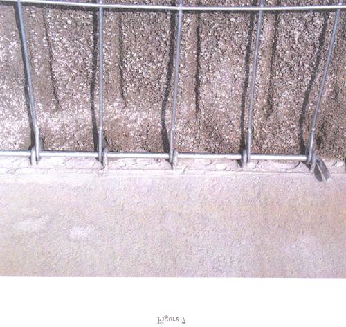
6 B. DELIVERY, STORAGE, AND HANDLING 1. Facing Panels Panels are delivered in stacks on flatbed trucks. If the panels are not to be erected directly from the delivery truck to the wall by using the lifting inserts, then the panels should be unloaded to a staging area by the use of a sling capable of handling the weight of a full stack. It should be noted that most freight companies allow one-hour time limit per load. If the panels are ever re-stacked, they should be placed face down on top of the plastic pads attached to the dunnage. Panels should never be placed directly on to the dunnage or ground as this can cause staining of the face, or damage to the connectors. Any connectors bent to such a degree to cause more than 50% of the galvanizing to be lost over a 1 section can be cause for rejection of the panel. Care should be taken to protect the panels from damage during handling. When placing the panels in the wall from the stack, wood blocks should be used as shown in Figure 1 to protect the bottom edge of the panel from damage. All unused dunnage should be collected and returned to Shaw Technologies, Inc. or its precaster. 2. Components Reinforcing Mesh the mesh comes to the jobsite bundled and can be placed directly on the ground as long as care is taken not to damage the galvanizing during handling. Alignment Pins, Poly Pads, Filter Cloth, and Adhesive these components should be stored in a secured storage area to prevent theft. The alignment pins will be bundled. The poly pads are boxed in quantities that facilitate easy handling. The filter cloth comes in 1-3 wide rolls and should be cut to length in the field and applied to the back of the panels utilizing the adhesive. 6
7 C. CONSTRUCTION PROCEDURES 1. Site Preparation Excavation the site should be excavated for the entire length, width and depth specified on the shop drawings. All unsuitable material should be removed and replaced with compacted fill if necessary. The base foundation should be proof rolled to a density suitable for the bearing pressure as per the project plans and specifications prior to forming the leveling pad. 2. Leveling Pad Construction All organics, soft soils or debris must be removed from the leveling pad location. The project engineer should inspect the leveling pad excavation prior to casting. The leveling pad shall be cast to lines and grades designated on the construction drawings. Steel reinforcement is not required in the leveling pad unless shown on the construction drawings. Care should be taken that the leveling pad is not cast above grade as high spots cause mis-alignment during construction. The leveling pads should be smooth and all stone, debris; etc. should be removed so that the pad is clean upon placement of the panels. A chalk line should be snapped on the surface of the pad to set the construction line of the wall. 3. Panel Layout Close attention to detail and accuracy will help insure rapid and trouble free construction. The leveling pad should be surveyed to indicate high and low areas so that shims may be placed underneath panels in low spots so that the top of the panel is to the correct grade. Lift the panels from the stacked position as shown in Figure 1 by use of the lifting pickup device as shown in Figure 2. Once the panel is lowered into place along the stringline, a spacer pad is used to set the correct spacing between the panel previously set and the panel that is being erected. Once the panels are in place, the alignment pins are dropped into place to aid erection of the panels above it. The panel sequence should be constructed using the sequence shown in Figure 4. The wood wedges and clamps as shown in Figure 3 are used to secure the panels together. Care should be taken to inspect the gap between adjacent panels to visually check the alignment and joint spacing around each panel. Adjustment should be made with a crowbar on the fill side of the panel on the bottom course of panels, and any shimming should be done to keep the panels at the same elevation. The vertical elevation of the panels should be checked and adjusted to insure that these panels are at the same elevation. A fourfoot level is used to verify both horizontal and vertical alignment. The next step is to set the batter of the full height panels designated as panels two, four, and six in Figure 4. These panels are given a slight batter toward the backfill side of the wall system to compensate for outward rotation caused by backfilling placement and compaction. Batter is usually measured using a four-foot level with a shim taped to the top of the level. Once the desired batter is achieved, the wedges are driven into the joints at the face of the wall. Additional clamps are secured to the top of the full height panel as shown in Figure 5. The batter boards are set in place by driving a stake into the natural ground and securing one end of the batter board to the stake and nailing the other 7
8 end to the clamp secured at the top of the full height panels. It should be noted that external bracing is only required for the first row of panels. It should also be noted that the wedges for each course of panels should remain in place during the construction of three subsequent courses and then removed. If the wedges remain in place for longer, they can be extremely difficult to remove. The amount of batter will vary depending upon the type of backfill used. Course backfills require less batter while fine backfills require more batter. The contractor should monitor the actual rotation of the panels during the initial phases of construction and adjust the batter accordingly. During construction, the overall vertical alignment of the structure should be checked periodically with the plumbbob. Once the initial course of panels has been erected and secured, the vertical joints should be covered by the filter cloth with the supplied adhesive as shown in Figure 6. As noted in Figure 5, the backfill should not be placed against the panel until the first layer of soil reinforcement has been secured and backfilled over. At that point, it is permissible to backfill against the face of the panel. 4. Soil Reinforcement Connection and Backfill Placement Place the approved backfill to the bottom of the soil reinforcement as shown in Figure 5. Backfill can be compacted t within three feet of the panels by use of a large vibratory roller. Within the three-foot zone directly behind the panels, a small hand operated compactor should be used to avoid excess panel movement. Once the backfill placement and compaction has reached the first layer of soil reinforcement, the type and length of reinforcement as designated on the plans shall be secured to the back of the precast panel. The mesh is placed into the connectors and the tie bar is pushed through the opening. It is very important that the outside longitudinal wires of the mesh are placed inside the outer most connectors as shown in Figure 7. Placement of the mesh in the correct manner restricts lateral movement of either the mesh or the precast panel. Occasionally because of manufacturing tolerances, the tie bar may not have solid contact between every connector and the longitudinal bars of the soil reinforcement. Should this occur, wood wedges can be driven between the back of the panel and the tie bar at approximately equal points along the width of the reinforcing mesh to insure positive contact. Backfill placement should continue similar to the technique used for the first lift of backfill to lock the mesh into place but not bury the wedges. Once the first lift over the mesh has been compacted, the wedges should be removed prior to the second lift being placed. All subsequent lifts should be carried up to the next level of reinforcement. The mesh should be fully supported by the compacted backfill for its full length prior to placing the next lift. The soil reinforcement should be level with no kinks or abrupt changes in direction. After the initial layer of reinforcement is secured, backfilling shall commence utilizing the same procedures as the previous steps. Extreme care must be exercised when placing backfill in the (3) three-foot area behind the initial course of panels through the reinforcing so that the mesh and connectors are not damaged (see Figure 5). The backfill should be spread by pushing the pile parallel to the panels and windrowing it toward the free ends of the soil reinforcement. If the embedment length of the soil reinforcement is long enough to require more than one dumping operation, the dumping should begin close to the panel and proceed away from the panel. In no event should a secondary dump be placed until the preceding backfill has been spread. Metal track earth moving equipment must never come in contact with the galvanized reinforcing mesh. Rubber tired vehicles may operate directly on the mesh if backfilling conditions permit and care is taken not to turn the equipment while directly on top of the mesh. Backfilling shall continue to the top of the first panel at 8
9 which time the poly pads that are used as the horizontal joint material should be placed on top of the panels. These should be placed at approximately third points along the width of the panel to distribute the load equally. 5. Subsequent Courses The alignment pins are set in the proper holes prior to placement of the subsequent course of panels. In addition, prior to placing these panels, the clamps should be removed from the lower corners similar to panels two, three and four as shown in Figure 4. When each subsequent course of panels is complete and the vertical joint material is installed, backfilling shall continue as previously constructed. After each level of backfilling, the batter and alignment should be checked and adjusted accordingly to insure that the wall is constructed within the specified tolerances. 6. Completion of the Wall The location of specific top panels is shown on the construction drawings. When installing a coping, the panels come in two variations. With cast-in-place coping, normally the panels will have rebar protruding from the tops to tie into the cast-in-place coping. With precast coping a level up strip should be cast to allow an even surface for setting the precast coping. In this instance, the top panels will not have rebar protruding from the top. After backfilling is complete and the coping is installed, all clamps and wedges should be removed from the wall. Consistency is the key to a satisfactory final wall alignment. When possible, specific crews should be assigned for the various operations to standardize procedures. 9
10 D. FIGURES 10
11 11
12 12
13 13
14 14
15 15
Reinforced Earth wall Construction Manual
 COVER PAGE CT-PE-W02 Rev: 5 Reinforced Earth wall Construction Manual Concrete Facing Reinforced Earth Malaysia Sdn Bhd 80-1, Jalan 8/62A Bandar Menjalara 52200 Kuala Lumpur Tel : 03-62746162, Fax : 03-62747212
T-WALL Retaining Wall System
 CONSTRUCTION MANUAL T-WALL Retaining Wall System The T-WALL Solution... THE NEEL COMPANY 8328 Traford Lane Springfield, VA 22152 Phone 703-913-7858 Fax 703-913-7859 T-WALL Retaining Wall System CONSTRUCTION
CONSTRUCTION MANUAL. T-WALL Retaining Wall System FOR RAILROAD PROJECTS. The T-WALL Solution...
 T-WALL Retaining Wall System CONSTRUCTION MANUAL FOR RAILROAD PROJECTS T-WALL railroad units are 5.0' high x 7.5' wide. (stem lengths will vary) The T-WALL Solution... T-WALL Retaining Wall System CONSTRUCTION
CONSTRUCTION MANUAL 2.5 x 5 UNITS
 CONSTRUCTION MANUAL 2.5 x 5 UNITS www.neelco.com 8328-D Traford Lane, Springfield, VA 22152 703 913 7858 T-WALL Retaining Wall System CONSTRUCTION Manual Contents Part I earthwork... 1 The Structure depends
CHAPTER 13 - MECHANICALLY STABILIZED EARTH WALLS AND PATENTED EARTH RETAINING SYSTEMS
 CHAPTER 13 - MECHANICALLY STABILIZED EARTH WALLS AND PATENTED EARTH RETAINING SYSTEMS DS Temple 13.1 SCOPE This section covers the inspection of mechanically stabilized earth walls and other patented earth
REINFORCED EARTH. Construction and Quality Control Procedures Manual. Construction Manual: Rectangular Panels. Rectangular Panels
 REINFORCED EARTH Construction Manual: Rectangular Panels Construction and Quality Control Procedures Manual Rectangular Panels CONSTRUCTION AND QUALITY CONTROL PROCEDURES MANUAL CONTENTS I. Preface...4
T R I C O N P R E C A S T L T D. TRICON RETAINED SOIL WALL SYSTEM CrimpLock Connection System CONSTRUCTION MANUAL
 T R I C O N P R E C A S T L T D. TRICON RETAINED SOIL WALL SYSTEM CrimpLock Connection System CONSTRUCTION MANUAL TRICON TM RETAINED SOIL WALL SYSTEM The Tricon TM Retained Soil Wall System is a mechanically
TRICON TM RETAINED SOIL WALL SYSTEM
 T R I C O N P R E C A S T L T D. TRICON TM RETAINED SOIL WALL SYSTEM CONSTRUCTION MANUAL TRICON TM RETAINED SOIL WALL SYSTEM The Tricon TM Retained Soil Wall System is a mechanically stabilized earth retaining
REINFORCED EARTH. Construction and Quality Control Procedures Manual. Construction Manual: Cruciform Panels. Cruciform Panels
 REINFORCED EARTH Construction Manual: Cruciform Panels Construction and Quality Control Procedures Manual Cruciform Panels CONSTRUCTION AND QUALITY CONTROL PROCEDURES MANUAL CONTENTS I. Preface...4 II.
Retaining Wall Systems
 Retaining Wall Systems Construction & Quality Control Tensar Earth Technologies, Inc. Manual CONSTRUCTION & QUALITY CONTROL This manual provides general guidelines for construction and quality control
SPECIFICATION FOR REINFORCED SOIL WALL
 SPECIFICATION FOR REINFORCED SOIL WALL 1.0 EXTENT OF WORK The work shall consist of Reinforced Soil walls built in accordance with this specification and in conformity with the lines, levels and details
T-WALL.
 The T-WALL Retaining Wall System is a gravity structure constructed of individual precast T-WALL units. Each T-WALL unit consists of a front face panel and a stem, which extends back into and engages the
Uwall UNIVERSAL CONSTRUCTION MANUAL
 Uwall UNIVERSAL Retaining Wall System CONSTRUCTION MANUAL TM President s Letter CSI is a leader in its industry supplying precast infrastructure products throughout New England and beyond since 1972, developing
CONSTRUCTION MANUAL 5-0 x 7-6 UNITS
 CONSTRUCTION MANUAL 5-0 x 7-6 UNITS www.neelco.com 8328-D Traford Lane, Springfield, VA 22152 703 913 7858 NOTE TO THE READER This manual has been prepared as a guide to building T-WALL Retaining Wall
CONCRETE SEGMENTAL RETAINING WALL SYSTEM
 CONCRETE SEGMENTAL RETAINING WALL SYSTEM PART 1: GENERAL SPECIFICATIONS 1.01 Work Included A. Work shall consist of furnishing and constructing a Rockwood Classic 8, Classic 6 and Legend unit segmental
Gravity Wall. A force to be reckoned with... Gravity (SRW) segmental retaining wall systems are structures
 segmental retaining wall systems are structures") A force to be reckoned with... Gravity (SRW) segmental retaining wall systems are structures lower in height that use the FrogStone unit weight combined with gravel core infill to resist earth pressures
A force to be reckoned with... Gravity (SRW) segmental retaining wall systems are structures lower in height that use the FrogStone unit weight combined with gravel core infill to resist earth pressures
ARES RETAINING WALL SYSTEMS. installation guide and construction manual
 ARES RETAINING WALL SYSTEMS installation guide and construction manual When long-term performance and speed of construction are important, ARES Retaining Wall Systems offer unmatched advantages. Tensar
T-WALL & STONE STRONG
 shawprecastsolutions.com & STONE STRONG Retaining Walls PRODUCT GUIDE & TECHNICAL REFERENCE MANUAL Providing the right solutions. The Retaining Wall System is a gravity structure constructed of individual
67665_MesaInstallationGuide_2 12/10/07 2:12 PM Page 1 E ID U G TION ALLA T INS
 INSTALLATION GUIDE Introduction The Mesa Retaining Wall Systems from Tensar International Corporation offer superior and costeffective solutions for all of your retaining wall needs. This installation
Construction Procedures
 Construction Procedures 2016 Rev. 1.7 1 Contents Introduction...... 3 Base Row Layout........ 4 Drainage and Backfill..... 6 Compaction... 7 Subsequent Rows... 8 In Pictures.... 10 Variations.. 11 Step
SECTION MECHANICALLY STABILIZED EARTH RETAINING WALLS
 SECTION 13100 MECHANICALLY STABILIZED EARTH RETAINING WALLS PART 1 -- GENERAL 1.01 THE REQUIREMENT A. Includes all labor, material, equipment, testing and submittals required to design and complete construction
Construction Procedures
 Construction Procedures 2014 Rev. 1.6 1 Introduction This manual presents the methods and procedures necessary for the proper erection of a LOCK+LOAD retaining wall. problems later during the service life
Description. This work shall consist of furnishing materials and placement of modular block wall constructed in accordance with
 MODULAR CONCRETE BLOCK RETAINING WALL WITH GROUND REINFORCING The Standard Specifications are revised as follows: 732-R-310r 1of 11 Rev. 12-03-03 SECTION 105, AFTER LINE 48, INSERT AS FOLLOWS: When constructing
SECTION TILT-UP PRECAST CONCRETE. A. Work includes, but is not limited to, the following:
 SECTION 03470 TILT-UP PRECAST CONCRETE PART 1 GENERAL 1.01 SUMMARY A. Work includes, but is not limited to, the following: 1. Precast wall panels. 2. Forms and casting beds. 3. Concrete. 4. Reinforcing
TILT-UP PRECAST CONCRETE SANDWICH PANELS. A. Work includes, but is not limited to, the following:
 PART 1 GENERAL 1.01 SUMMARY SECTION 03460 TILT-UP PRECAST CONCRETE SANDWICH PANELS A. Work includes, but is not limited to, the following: 1. Architectural precast concrete sandwich wall panels. 2. Integral
SPECIFICATION FOR MAGNUMSTONE GEOGRID REINFORCED Mechanically Stabilized Earth (MSE) SYSTEM
 SYSTEM") MagnumStone Specifications Geogrid Reinforced SPECIFICATION FOR MAGNUMSTONE GEOGRID REINFORCED Mechanically Stabilized Earth (MSE) SYSTEM PART 1: GENERAL 1.01 Description The work consists of supplying
MagnumStone Specifications Geogrid Reinforced SPECIFICATION FOR MAGNUMSTONE GEOGRID REINFORCED Mechanically Stabilized Earth (MSE) SYSTEM PART 1: GENERAL 1.01 Description The work consists of supplying
INS T A LLA T I O N G U I D E
 INS T A LLA T I O N G U I D E TENSAR GEOGRIDS The System is a costeffective and easy-to-install alternative for projects with grade changes. The System owes its long-term performance and durability to
MagnumStone Specifications Gravity
 MagnumStone Specifications Gravity SPECIFICATION FOR MAGNUMSTONE GRAVITY MECHANICALLY STABILIZED EARTH SYSTEM PART 1: GENERAL.01Description The work consists of supplying and installing all aspects of
SECTION TILT-UP PRECAST CONCRETE SANDWICH PANELS. A. Work includes, but is not limited to, the following:
 PART 1 GENERAL 1.01 SUMMARY SECTION 03460 TILT-UP PRECAST CONCRETE SANDWICH PANELS A. Work includes, but is not limited to, the following: 1. Architectural precast concrete sandwich wall panels. 2. Integral
UPRR INDUSTRIAL LEAD BRIDGE T-WALL RETAINING WALL SYSTEM 5.0 x 7.5 UNITS DESIGN UNIT 018 WORK PACKAGE 04
 UPRR INDUSTRIAL LEAD BRIDGE T-WALL RETAINING WALL SYSTEM 5.0 x 7.5 UNITS DESIGN UNIT 018 WORK PACKAGE 04 1. Description This work shall consist of the design, manufacture and construction of a T-WALL structure
SPECIFICATIONS FOR PRECAST MODULAR BLOCK RETAINING WALL SYSTEM (revised 5/8/7)
") Page 1 of 7 STONE STRONG SYSTEMS SPECIFICATIONS FOR PRECAST MODULAR BLOCK RETAINING WALL SYSTEM (revised 5/8/7) PART 1: GENERAL 1.01 Description A. Work includes furnishing and installing precast modular
Page 1 of 7 STONE STRONG SYSTEMS SPECIFICATIONS FOR PRECAST MODULAR BLOCK RETAINING WALL SYSTEM (revised 5/8/7) PART 1: GENERAL 1.01 Description A. Work includes furnishing and installing precast modular
Notes for Erection of Evergreen Maxi Wall Retaining Walls
 Notes for Erection of Evergreen Maxi Wall Retaining Walls 1. Evergreen Maxi General Notes A. Project drawings - See project drawings for complete layout of utilities, railroad tracks, existing and proposed
Installation Manual. ArchCast Bridge. 3-Sided Precast Concrete Bridge Structure
 ArchCast Bridge 3-Sided Precast Concrete Bridge Structure Installation Manual Salem Location: 749 West Commercial Ave. Salem, IL 62881 (618) 548-1190 countymaterials.com Email: info@countymaterials.com
BELMURO WALL SYSTEM INSTALLATION GUIDE
 BELMURO WALL SYSTEM INSTALLATION GUIDE TABLE OF CONTENTS TABLE OF CONTENTS... 1 SYSTEM DESCRIPTION... 2 DRY STACK SYSTEM: INSTALLATION GUIDE... 5 GEOGRID WALL SYSTEM: INSTALLATION GUIDE... 9 MASONRY WALL
CONTENT. INTrOduCTION 3. units & CONNECTOrs 4. standard INsTallaTION PrOCEdurEs 5
 CONTENT INTrOduCTION 3 units & CONNECTOrs 4 standard INsTallaTION PrOCEdurEs 5 step 1 - Preconstruction Preparation 5 step 2 - Prepare the leveling Pad 5 step 3 - Install the Base Course 5 step 4 - Geogrid
SECTION SPECIFICATION FOR STONEBRIDGE RETAINING WALL SYSTEM
 SECTION 32 32 23 SPECIFICATION FOR STONEBRIDGE RETAINING WALL SYSTEM PART 1: GENERAL 1.01 Scope Work includes furnishing all materials, labor, equipment, and supervision to install a Stonebridge segmental
SPECIFICATIONS FOR PRECAST MODULAR BLOCK RETAINING WALL SYSTEM (revised 9/17/18)
") Page 1 of 8 STONE STRONG SYSTEMS SPECIFICATIONS FOR PRECAST MODULAR BLOCK RETAINING WALL SYSTEM (revised ) PART 1: GENERAL 1.01 Description A. Work includes furnishing and installing precast modular blocks
Page 1 of 8 STONE STRONG SYSTEMS SPECIFICATIONS FOR PRECAST MODULAR BLOCK RETAINING WALL SYSTEM (revised ) PART 1: GENERAL 1.01 Description A. Work includes furnishing and installing precast modular blocks
SECTION 503 TEMPORARY PAVEMENT RESTORATION
 SECTION 503 TEMPORARY PAVEMENT RESTORATION 503-1 DESCRIPTION: This work consists of furnishing, placing, compacting, and maintaining a temporary pavement surface suitable for driving in accordance with
CONCRETE SEGMENTAL FREESTANDING WALL SYSTEM
 CONCRETE SEGMENTAL FREESTANDING WALL SYSTEM PART 1: GENERAL SPECIFICATIONS 1.01 Work Included A. Work shall consist of furnishing and constructing a Lakeland TM unit segmental freestanding wall in accordance
STANDARD SPECIFICATION FOR CRIBLOCK CONCRETE CRIBWALL
 STANDARD SPECIFICATION FOR CRIBLOCK CONCRETE CRIBWALL 1. SCOPE 2. DESIGN 3. MATERIALS 4. CONSTRUCTION 5. METHOD OF MEASUREMENT AND PAYMENT SCOPE This Specification sets out requirements for the design,
GEOGRID CONNECTION DETAIL OLYMPIA RADIUS UNIT
 PLACE TWO STANDARD CONNECTORS IN EACH UNIT AS SHOWN (VERTICAL ORIENTATION) INSERT TWO CONNECTORS PER HORIZONTALLY ORIENTED BLOCK; INSERT ONE CONNECTOR PER VERTICALLY ORIENTED BLOCK SHIM BETWEEN BLOCK COURSES
LANDSCAPE RETAINING WALLS
 SUDAS Standard Specifications Division 9 - Site Work and Landscaping Section 9070 - Landscape Retaining Walls LANDSCAPE RETAINING WALLS PART - GENERAL.0 SECTION INCLUDES A. Modular Block Retaining Walls
StormPod Arch Installation Guide
 StormPod Arch Installation Guide xx Foundation Bed Preparation Use standard construction procedures for the construction of the bed for StormPod Modular Arch Systems. As with any construction project,
Premier Railroad Grade Crossing Installtion Guide PREMIER RAILROAD GRADE CROSSING INSTALLTION GUIDE GUIDE GROUNDED IN STRENGTH
 Premier Railroad Grade Crossing Installtion Guide PREMIER RAILROAD GRADE CROSSING INSTALLTION GUIDE GUIDE GROUNDED IN STRENGTH RELIABILITY STARTS WITH A WELL-DESIGNED PLAN. THE RIGHT PRODUCT FOR THE RIGHT
CONSTRUCTION MANUAL for Railroad Projects
 CONSTRUCTION MANUAL for Railroad Projects www.neelco.com 8328-D Traford Lane, Springfield, VA 22152 703 913 7858 NOTE TO THE READER This manual has been prepared as a guide to building T-WALL Retaining
Redi Rock Specification and Installation Manual
 Redi Rock Specification and Installation Manual 1.0 General Scope This Specification covers the Design, Materials and Installation of Redi Rock modular block Retaining and Freestanding Wall systems as
ON GUIDE I T A L L A T S
 INSTALLATION GUIDE When long-term performance and speed of construction are concerns, ARES Retaining Wall Systems offer unmatched advantages. Tensar Geogrids The ARES Retaining Wall Systems owe their strength
MSE WALLS CASE STUDIES. by John G. Delphia, P.E. TxDOT Bridge Division Geotechnical Branch
 MSE WALLS CASE STUDIES by John G. Delphia, P.E. TxDOT Bridge Division Geotechnical Branch COMMON RETAINING WALL TYPES CONCRETE BLOCK MSE TEMPORARY EARTH SPREAD FOOTING Gabions Drilled Shaft Soil Nail Tiedback
A. Modular Unit - A concrete wall interlocking element, machine made from portland cement, water and aggregates.
 Section 02832 - Page 1 PART 1 - GENERAL 1.1 SUMMARY 1.2 DEFINITIONS 1.3 SUBMITTALS 1.4 JOB MOCK-UP A. This section includes furnishing and installation of modular interlocking concrete masonry units bearing
INDEX FOR SPECIFICATIONS FOR REMOVING CULVERTS AND PLACING CULVERTS SCOPE... 1
 March 2002 No. 400 INDEX FOR SPECIFICATIONS FOR REMOVING CULVERTS AND PLACING CULVERTS 400. 1 SCOPE... 1 400. 2 REMOVING CULVERTS AND TIMBER STRUCTURES 2.1 Concrete and Metal Pipe Culverts... 1 2.2 Structural
TERRASTOP SYSTEM 2 RETAINING WALLS. Section Page 1 PART 1 - GENERAL 1.1 SUMMARY
 Section 02832 - Page 1 PART 1 - GENERAL 1.1 SUMMARY 1.2 DEFINITIONS 1.3 SUBMITTALS 1.4 JOB MOCK-UP A. This section includes furnishing and installation of modular interlocking concrete masonry units bearing
SECTION MECHANICALLY STABILIZED EARTHEN SLOPES. Display hidden notes to specifier by using Tools / Options / View / Hidden Text.
 PART 1 GENERAL SECTION 02260 MECHANICALLY STABILIZED EARTHEN SLOPES Display hidden notes to specifier by using Tools / Options / View / Hidden Text. 1.1 SECTION INCLUDES A. ** NOTE TO SPECIFIER ** Delete
Rapid Axial Load Testing of Drilled Shafts
 Supplemental Technical Specification for Rapid Axial Load Testing of Drilled Shafts SCDOT Designation: SC-M-712 (9/15) September 4, 2015 1.0 GENERAL This work shall consist of performing a rapid axial
SECTION STORM DRAINAGE
 SECTION 02720 STORM DRAINAGE PART 1 - GENERAL 1.01 WORK INCLUDED A. Trenching and other excavation. B. Ground water control. C. Pipe bedding. D. Installation of storm drains and appurtenances. E. Installation
SANDERS PRE-CAST CONCRETE SYSTEMS, INC. MSE WALL SYSTEM SUBMITTAL
 SANDERS PRE-CAST CONCRETE SYSTEMS, INC. MSE WALL SYSTEM SUBMITTAL FLORIDA DEPARTMENT OF TRANSPORTATION THE SANDERS COMPANIES 605 SOUTH INDIANAPOLIS ROAD WHITESTOWN, IN 46075 09-8-5 ISSUED FOR REVIEW REVISIONS/ISSUE
INSTALLATION GUIDE A Unique Retaining Wall System That s Engineered to Last!
 INSTALLATION GUIDE A Unique Retaining Wall System That s Engineered to Last! Safety Safety is the number one concern of Big Block, Inc. It s of utmost importance that Big Block walls be installed in a
Monumental Blok. Pallet Overview. Compatible caps. Notes. code 3521 (a) 3522 (b) 3523 (c) texture Chiseled. Specifications per pallet.
 3522 (b) 3523 (c) texture Chiseled. Specifications per pallet.") Monumental Blok code 3521 (a) 3522 (b) 3523 (c) texture Chiseled Pallet Overview (see below) HALF Specifications per pallet Imperial Metric Cubing 13.80 ft 2 /pal. (1.28 m 2 )/pal. 1.73 ft 2 /unit (0.16
Monumental Blok code 3521 (a) 3522 (b) 3523 (c) texture Chiseled Pallet Overview (see below) HALF Specifications per pallet Imperial Metric Cubing 13.80 ft 2 /pal. (1.28 m 2 )/pal. 1.73 ft 2 /unit (0.16
Garden WallScape Installation Guide
 By CornerStone Wall Solutions Inc. Garden WallScape Installation Guide GRAVITY/DETAILS The perfect balance... between design and nature Garden WallScape Overview note: bolded terms are defined in our online
DIVISION 4100 SITEWORK
 DIVISION 4100 SITEWORK SECTION 4115 EARTHWORK PART 1 - GENERAL 1.01 SCOPE This section covers the grading and compaction of excavations, embankments, structural foundations, and planted areas. 1.02 REFERENCES
STATE OF OHIO DEPARTMENT OF TRANSPORTATION SUPPLEMENTAL SPECIFICATION 840 MECHANICALLY STABILIZED EARTH WALL. January 19, 2007
 STATE OF OHIO DEPARTMENT OF TRANSPORTATION SUPPLEMENTAL SPECIFICATION 840 MECHANICALLY STABILIZED EARTH WALL January 19, 2007 840.01 Description 840.02 Definitions 840.03 Materials 840.04 Design and Submittal
Bordeaux Walling. Product & Technical Information
 Product & Technical Information BORDEAUX WALLING Piece Piece Piece Block Block Block Block Pins No. per per Height Length Width Weight Layer Cube (kgs) 1 2 3 1 2 10 150 400/350 250 28 Yes 2 2 10 150 300/300
 Civil and Structural Engineering CONSTRUCTION OF BRIDGE STRUCTURES SHALL BE IN ACCORDANCE WITH THE FOLLOWING SPECIFICATIONS, LISTED IN ORDER OF PRECEDENCE: 1. CDOT STANDARD SPECIFICATIONS FOR ROAD AND
STATE OF OHIO DEPARTMENT OF TRANSPORTATION SUPPLEMENTAL SPECIFICATION 867 TEMPORARY WIRE FACED MECHANICALLY STABILIZED EARTH WALL.
 STATE OF OHIO DEPARTMENT OF TRANSPORTATION SUPPLEMENTAL SPECIFICATION 867 TEMPORARY WIRE FACED MECHANICALLY STABILIZED EARTH WALL April 15, 2016 867.01 Description 867.02 Definitions 867.03 Materials 867.04
Section ( ) SPECIFICATION FOR SEGMENTAL CONCRETE UNIT RETAINING WALL
 SPECIFICATION FOR SEGMENTAL CONCRETE UNIT RETAINING WALL") Section 02834 (32 32 23) SPECIFICATION FOR SEGMENTAL CONCRETE UNIT RETAINING WALL PART 1: GENERAL 1.01 Description A. Work shall consist of furnishing and construction of a County Materials Retaining Wall
Section 02834 (32 32 23) SPECIFICATION FOR SEGMENTAL CONCRETE UNIT RETAINING WALL PART 1: GENERAL 1.01 Description A. Work shall consist of furnishing and construction of a County Materials Retaining Wall
ThermaSteel Corporation ASSEMBLY MANUAL
 ThermaSteel Corporation ASSEMBLY MANUAL TABLE OF CONTENTS 1- INTRODUCTION 1.1 THERMASTEEL TM WALL PANELS 1.2 Drawing and Element Numbers 2- ASSEMBLY 2.1 Sequence of Assembly 2.2 Preparation of Foundation
Important: Before You Start
 Advantage ICF System Advantage ICF System TM Field Guide Important: Before You Start Does Your Building Inspector Know You Are Building with the Advantage ICF System? You are required to check with your
Section REINFORCING STEEL
 Section 03210 PART 1 GENERAL 1.01 SUMMARY This Section includes the furnishing and subsequent placing of reinforcing steel, deformed and smooth, chairs, ties, splicing devices, and other reinforcing accessory
Construction Specification for Utility Adjustments
 Engineering & Construction Services Division Standard Specifications for Road Works TS 4.50 September 2017 for Utility Adjustments Table of Contents TS 4.50.01 SCOPE... 2 TS 4.50.02 REFERENCES... 2 TS
SECTION BUILDING EARTHWORK
 Conditions of Use/ Responsibility of Data Montgomery County Public Schools Facilities Guide DIVISION 2 - SITE WORK These guideline specifications are to be used by the A/E as a base document in the development
R-TANK SPECIFICATIONS
 TECHNICAL STORMWATER MANAGEMENT R-TANK SPECIFICATIONS PART 1 GENERAL 1.01 Related Documents A. Drawings, technical specification and general provisions of the Contract as modified herein apply to this
GABIONS AND REVET MATTRESSES
 GABIONS AND REVET MATTRESSES PART 1 - GENERAL 1.01 SECTION INCLUDES A. Gabions B. Revet Mattresses (Gabion Mattresses) 1.02 DESCRIPTION OF WORK A. Assembly and installation of gabions. B. Assembly and
1 Exam Prep Placing Reinforcing Bars Tabs and Highlights
 1 Exam Prep Placing Reinforcing Bars Tabs and s These 1 Exam Prep Tabs are based on the CRSI Placing Reinforcing Bars Recommended Practices, 9 th Edition. Each 1 Exam Prep tabs sheet has five rows of tabs.
FLORIDA DEPARTMENT OF TRANSPORTATION
 TEMPORARY WIREWALL MSE RETAINING WALLS SAMPLE DETAIL DRAWINGS INDEX DESCRIPTION 1 TITLE 2 GENERAL NOTES 3-4 TEMPORARY WIREWALL DETAILS 5-6 TRI-WEB TEMPORARY WALL DETAILS 7 TYPICAL TEMPORARY WIREWALL 8
Installation Guidelines
 815 NE 172 nd Avenue Vancouver, WA 98684 877-694-0141 Installation Guidelines Installation steps include job planning, layout, excavating and preparing the soil subgrade, applying geotextiles (optional),
SECTION 39 - MANHOLES TABLE OF CONTENTS
 Section SECTION 39 - MANHOLES TABLE OF CONTENTS Page 39-1 GENERAL... 39.1 39-2 CONCRETE MANHOLES... 39.1 39-2.01 NOT USED... 39.1 39-2.02 Concrete Storm Drain Manholes... 39.1 39-3 SADDLE SEWER MANHOLES...
SECTION Segmental Concrete Unit Masonry Retaining Wall Height Over 5-0 High
 PART 1: GENERAL 1.0 0 Scope of Standards A. This standard provides general guidance concerning the specific preferences of the Texas State University for a Segmental Retaining Wall up to 5-0 high. B. Texas
Section ( ) MODULAR CONCRETE RETAINING WALL
 MODULAR CONCRETE RETAINING WALL") Section 02834 (32 32 23) MODULAR CONCRETE RETAINING WALL PART 1: GENERAL 1.01 Description A. Work shall consist of furnishing and construction of a KEYSTONE 133Elite Unit Retaining Wall System or equal
Section 02834 (32 32 23) MODULAR CONCRETE RETAINING WALL PART 1: GENERAL 1.01 Description A. Work shall consist of furnishing and construction of a KEYSTONE 133Elite Unit Retaining Wall System or equal
Technical Data Sheet NEC/GRAN/95:01
 Technical Data Sheet NEC/GRAN/95:01 Installation Guidance Notes Granular Surround Note : These guidance notes refer only to the installation of Granular surround underground tanks. These guidance notes
MODULAR CONCRETE RETAINING WALL
 MODULAR CONCRETE RETAINING WALL PART 1: GENERAL 1.01 Description A. Work shall consist of furnishing and construction of a KEYSTONE Retaining Wall System or equal in accordance with these specifications
Site Preparation... 2
 TRUFIREWALLS INSTALLATION MANUAL This Installation Manual is intended to assist in the preparation and installation of TruFireWalls products manufactured by Oldcastle Enclosure Solutions. The TruFireWalls
SECTION SEGMENTAL RETAINING WALL
 Note: This guide specification should not be included entirely as-is. Specification writers must edit areas in red which may or may not be relevant to a specific project or where mutually exclusive choices
DESIGNING AND CONSTRUCTION OF T-WALL RETAINING WALL SYSTEM
 Istanbul Bridge Conference August 11-13, 2014 Istanbul, Turkey DESIGNING AND CONSTRUCTION OF T-WALL RETAINING WALL SYSTEM T. C. NEEL and K.BOZKURT ABSTRACT This work shall consist of the design, manufacture
1 Exam Prep Prov Module: Vertical Formwork Questions and Answers
 1 Exam Prep Prov Module: 27308-14 Vertical Formwork Questions and Answers 1. The amount of formwork needed for a job can be influenced by. A. The size of the forming crew B. The project budget C. Materials
Health & Safety Policy and Procedures Manual SECTION 23 MASONRY CONSTRUCTION
 SECTION 23 MASONRY CONSTRUCTION 1. Masonry Construction: A. Whenever a masonry wall is being constructed, a limited access zone will be established prior to construction meeting the following requirements.
Interior Hangers. Application
 Application Interior bridge deck hangers are typically fabricated using two heavy duty sheet metal end clips that have been electrically resistance welded to an appropriate sized wire or formed metal connecting
Section (02830) MODULAR CONCRETE RETAINING WALL
 MODULAR CONCRETE RETAINING WALL") Section 323223 (02830) MODULAR CONCRETE RETAINING WALL PART 1: GENERAL 1.01 Description A. Work shall consist of furnishing and constructing a VERDURA Retaining Wall System (or approved equal) in accordance
Section 323223 (02830) MODULAR CONCRETE RETAINING WALL PART 1: GENERAL 1.01 Description A. Work shall consist of furnishing and constructing a VERDURA Retaining Wall System (or approved equal) in accordance
APPENDIX A MEASUREMENT AND PAYMENT
 P-150 DEMOLITION 4.01 Removal of pavement shall be measured per square yard based on the area shown on the plans. Any pavement removed outside the designed limits of removal because the pavement was damaged
A-ONE Insulated Forms Installation Manual
 A-ONE Insulated Forms Installation Manual Rockford, MN www.aoneform.com www.diversifoam.com info@diversifoam.com A-ONE Manual 180426.docx Disclaimer Notice The information in the A-ONE Insulated Forms
SECTION SEGMENTAL CONCRETE UNIT MASONRY RETAINING WALL MAXIMUM HEIGHT OF 5-0 HIGH
 DIVISION 32 EXTERIOR IMPROVEMENTS SECTION 32 32 23.13 SEGMENTAL CONCRETE UNIT MASONRY RETAINING WALL MAXIMUM HEIGHT OF 5-0 HIGH PART 1: GENERAL 1.01 Scope of Standards A. This standard provides general
Wmega Retaining Wall Specification
 Wmega Retaining Wall Specification 1. General 1.01 Description A. This work shall consist of furnishing and installing an Ωmega Segmental Retaining Wall System in accordance with these specifications and
SECTION CONCRETE FORMWORK
 SECTION 03100 CONCRETE FORMWORK PART 1 GENERAL 1.1 REFERENCES A. The following is a list of standards which may be referenced in this section: 1. American Concrete Institute (ACI): a. 117, Standard Specifications
STATE OF OHIO DEPARTMENT OF TRANSPORTATION SUPPLEMENTAL SPECIFICATION 840 MECHANICALLY STABILIZED EARTH WALL. July 18, 2014
 STATE OF OHIO DEPARTMENT OF TRANSPORTATION SUPPLEMENTAL SPECIFICATION 840 MECHANICALLY STABILIZED EARTH WALL July 18, 2014 840.01 Description 840.02 Definitions 840.03 Materials 840.04 Design and Submittal
G R A V I T Y / G E O G R I D
 GRAVITY/GEOGRID MAGNUMSTONE Overview note: bolded terms are defined in our online glossary at www.cornerstonewallsolutions.com The MagnumStone retaining wall system was developed with the installer in
COUNTY BLOCK. Construction Guidelines on County Block Steps. Special Considerations When Building Steps. Natural Beauty Absolute Strength
 Construction Guidelines on County Block Limits of Liability This County Block Installation Guide provides general information about the product, including installation procedures, technical and engineering
SECTION PERMEABLE INTERLOCKING CONCRETE UNIT PAVEMENT
 SECTION 32 14 13 19 PERMEABLE INTERLOCKING CONCRETE UNIT PAVEMENT SECTION 32 14 13 19 PERMEABLE INTERLOCKING CONCRETE UNIT PAVEMENT PART 1 - GENERAL 1.1 SUMMARY A. Section Includes: 1. Permeable Articulating
NOVEMBER 2016 GRANDWALL. retaining walls installation guide
 NOVEMBER 2016 GRANDWALL retaining walls installation guide RETAINING WALL INSTALLATION GUIDE RETAINING WALL information Austral Masonry Grandwall retaining wall blocks are an ideal choice for retaining
BIO-AQUIFER STORM SYSTEM
 BIO-AQUIFER STORM SYSTEM Specifications for Construction PART 1 GENERAL 1.01 SECTION INCLUDES A. Providing labor, materials, tools and equipment to furnish and install a permeable concrete paving stone