ALCO Cable Gland Tutorial
|
|
|
- Magnus Booker
- 5 years ago
- Views:
Transcription


1 ALCO Cable Gland Tutorial Selection and fitment of Hazardous Area SWA Cable Glands Phone:
2 Steel Wire Armoured Cable Consider the construction of SWA cables, starting at the outside diameter (OD) There is a PVC or XLPE sheath that covers the entire cable that is required to have an environmental seal. Underneath that covering are protective steel wires that are wrapped around the rest of the cable build to provide flexible/mechanical protection as well as a current path to earth for fault protection via the SWA grounding cones. Underneath the steel wires, there is another protective sheath that also requires an environmental seal. Under this sheath sometimes finds additional brass tapes or a nylon jacket. The balance of the cable build is made up of the insulated conductors which are electrical terminated to carry the required load. In Hazardous area fitment, the requirement of the gland is not only to provide tortuous path, earth bonding of the SWA and environmental sealing, But to also consider seal dimension and characteristics as well as special thread dimensions to provide managed expansion of air pressure or gas pressure from one environment to another.
3 Gland Selection It is imperative that the correct cable gland to suit the fitting environment is selected. Hazardous Areas must have compliant Hazardous Area Glands See the following page or refer to page 2 of the Alco catalogue for classifications. This information is also available online at

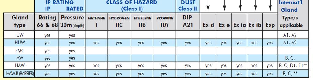
4 Hazardous Area Gland Classification
5 HAW and HAW-B HAW Hazardous Armoured gland Termination: HAW Gland Assembly HAW-B Hazardous Armoured Barrier gland Termination HAW-B Gland Assembly In most cases references to explosion proof will pertain to barrier glands.
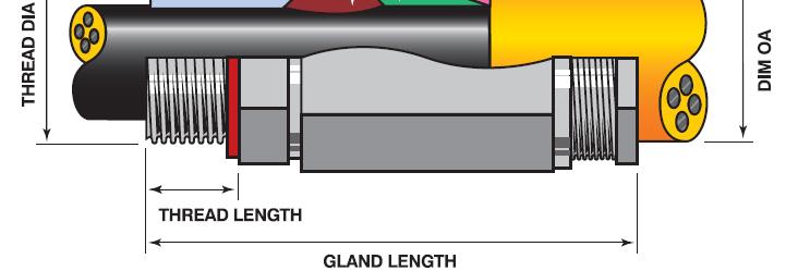
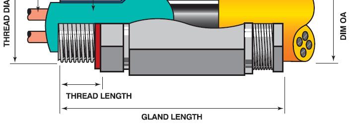
6 Critical Dimensions for Gland selection Overall Diameter (OD) This is the outside or overall diameter of the cable, where the OD seal will fit. SWA Diameter This is the individual diameter of the protective steel wires in the armour. Over Bedding Diameter (OB) This is the diameter of the insulation, underneath the SWA. Under Bedding Diameter This is the diameter underneath the bedding but over the sheath covering the multicores, where the OB seal will fit.
7 Critical Dimensions for Gland selection It is necessary that each cable is check measured prior to fitment of glands due to manufacturing inconsistencies in the dimensions of cable. It is quite common for cables to be +/-1 or 2mm different than catalogued sizes. Dimensions from the beginning, middle and end of a drum can vary as can the diameter from one batch over many cable drums.
8 Critical Dimensions for Termination In each case, HAW or HAW-B, there are dimensions quoted in the relative gland tables for exposed lengths of SWA and bedding. Arbitrary or random SWA lengths cause a lot of trouble at termination, so adherence to the quoted dimensions is critical. i.e. If SWA is left too long then there will be issues trying to fit the sleeve, affecting the seal on the bedding and OD.
9 HAW GLANDS Typically this style of gland not only offers IP68 weather protection but also offers tortuous path or mechanical securing and earth bonding of the Steel Wire Armour. In addition to the primary function of this gland is the suitability to Hazardous area fitment. Flame path threads and seals are different to the normally used AW gands.

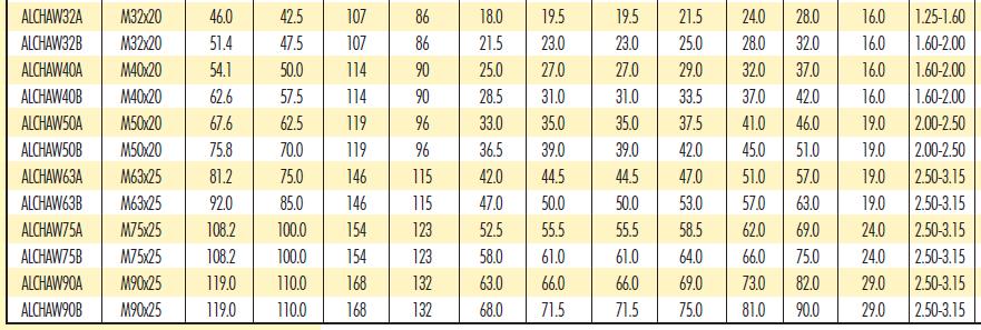
10 HAW Gland Table
11 HAW Hazardous SWA Establish the suitable HAW Gland for the termination application. In the sealed packet there will be 1 seal to suit the OD of the cable. Also there will be two seals, A and B to suit a flexible range of OB dimensions for that gland. Establish the correct seal to use and discard the other. Also discard the brass cone insert as it is not used in this application.

12 HAW Assembly
13 HAW Gland Assembly 1. Pass the Gland nut and OD seal over the end of the cable to be terminated. 2. Determine the length of the tail, removing the sheath with a cable knife or Jokari stripper 3. Remove the SWA leaving the required exposed length determined from the gland instruction sheet (Dimension E ). 4. Pass the sleeve and clamping ring over the SWA and then slide the cone over the bedding and under the SWA. You may need to pre-bend the SWA to do this with smaller size cables. 5. Screw the body of the gland into the enclosure by screwing into the tapped thread for fitment. Ensure the fibre washer provided is used to retain the IP68 and EX rating.slide the appropriate inner seal over the bedding and ensure it is butted up to the cone. 6. Slide the cable through the fitted gland body, ensuring that the SWA butts up against the cone face.
14 7. Maintaining pressure, so that the inner seal, cone and armour remain in place, slide the clamping ring, and sleeve against the SWA and tighten. 8. Slide the OD seal into the fitted gland assembly. Apply a small amount of cable pulling lubricant onto the exposed surface of the OD seal to allow for easy assembly when the gland nut is now pushed up to meet the threads of the gland assembly. 9. Tighten the gland nut as per specifications supplied. These instructions are also printed in the Alco Gland Catalogue and are also available on the website;
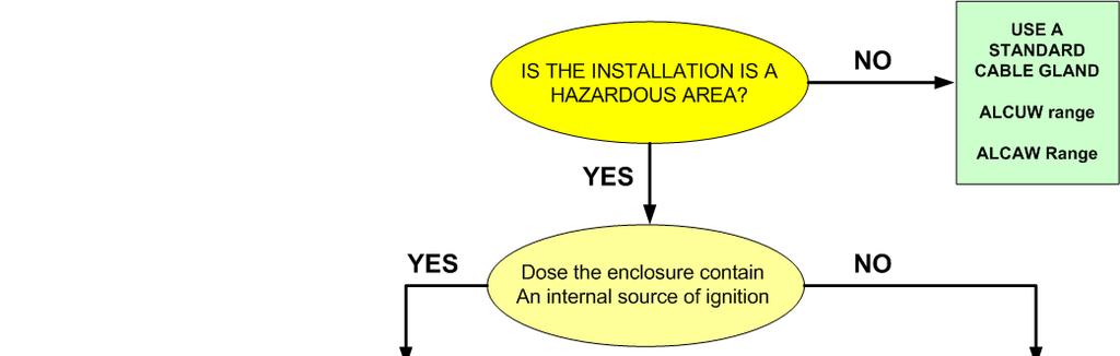
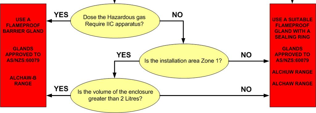
15 HAW To B or not to B Barrier glands are typically used in applications where standard glands featuring elastomeric seals are insufficient. Barrier glands are similar to standard hazardous area cable glands, except an epoxy compound sealant (insulputty) is required to be used to seal around the individual cores and the gland. This is done to ensure the inside and outside of the cable remain liquid tight. Furthermore, the following questions need to be answered to establish whether a barrier gland is required.
16 Is the cable round, compact and effectively filled? Yes-> move to next question No-> barrier gland is required Does the enclosure have an internal source of ignition? Yes-> move to next question No-> standard gland may be used Does the hazardous gas require IIC apparatus? Yes-> barrier gland should be used No-> standard to next question Is the installation area zone 1? Yes-> move to next question No-> standard gland may be used Is the volume of the enclosure greater than 2 litres? Yes-> barrier gland should be used No-> standard gland may be used
17
18 HAW-B GLANDS In addition the primary function of this gland and its suitability to Hazardous area fitment, application of epoxy putty can be applied between the cores of a multicore cable to ensure the integrity of the flame path. This is important where in cable construction, the inner cores do not allow for symmetrical or regular diameters for ordinary seals to fit well.

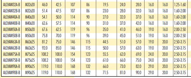
19 HAW-B Gland Table
20 HAW B Hazardous SWA BARRIER Establish the suitable HAW-B Gland for the termination application. In the sealed packet there will be 1 seal to suit the OD of the cable. Pay particular attention to the dimension Under bedding, that is over the multicores. Discard the OB seals as the brass cone insert is used in this application.

21 HAW B ASSEMBLY
22 HAW-B Gland Assembly 1. Pass the Gland nut and OD seal over the end of the cable to be terminated. 2. Determine the length of the tail, removing the sheath with a cable knife or Jokari stripper 3. Remove the SWA leaving the required exposed length Dimension E determined from the gland instruction sheet. 4. Trim the bedding so that the exposed length beyond the SWA equal to dimension G determined from the gland instruction sheet. 5. Spread the exposed cores of the cable and remove any fillers or tapes without damaging the insulation on the conductors. 6. Pass the sleeve and clamping ring over the SWA and then slide the cone over the bedding and under the SWA. You may need to pre-bend the SWA to do this with smaller size cables. 7. Screw the body of the gland into the enclosure by screwing into the tapped thread for fitment or by use of a locknut. Ensure the fibre washer provided is used to retain the IP68 and EX rating.
23 8. The epoxy filling compound is a two part product that must be thoroughly mixed so that it has an even colour. Where larger glands are supplied with multiple packets of compound, mix each pack separately and then apply collectively whilst all fill is pliable in one application. The compound has a working life of around 40 minutes at ambient temperatures of 25 degrees. Use of the supplied disposable gloves is not essential however, is recommended for those with sensitive skin or where prolonged exposure is anticipated. Mix the epoxy compound. 9. Pack the compound between the exposed cores starting at the centre and working outwards, for the length of cable equal to the length of the supplied brass insert. Ensure that as you work the epoxy compound inwards to outwards, the cable cores return to their original position and all are fully coated with the compound. Additionally ensure there is sufficient compound to completely fill the bell shaped end of the brass insert. 10. Slide the insert over the epoxy filled cores, removing excess compound as required, until the brass insert mates onto the cone. 11. Slide the cable through the fitted gland body, ensuring that the brass insert remains mated with the cone and that the SWA butts up against the cone face.
24 12. Slide the clamping ring and sleeve onto the SWA. Tighten the sleeve whilst ensuring that the SWA is not allowed to slip back from the cone face or that the brass insert does not part from the cone during this tightening process. 13. Slide the OD seal into the fitted gland assembly. Apply a small amount of cable pulling lubricant onto the exposed surface of the OD seal to allow for easy assembly when the gland nut is now pushed up to meet the threads of the gland assembly. 14. Tighten gland nut as per specifications supplied. 15. Leave the assembled gland for three hours to allow for the epoxy compound to cure. After curing, the gland may be disassembled for inspection or maintenance. These instructions are also printed in the Alco Gland Catalogue and are also available on the website;
25
26 ALCO Cable Gland Tutorial Thankyou! For your attention Phone:
EXPLOSION-PROOF CABLE GLAND - Type ICG 623 Manual
 fax. +31 (0)227-549 150 EXPLOSION-PROOF CABLE GLAND - Type ICG 623 Manual EXPLOSION PROOF Page 2 of 8 EXPLOSION PROOF Page 3 of 8 Operating temperature range -60 C +80 C Certification Details Gland Type:
SECTION EARTHING AND EARTH FAULT PROTECTION
 SECTION 16660 PART 1 - GENERAL 1.01 DESCRIPTION A. The work to be performed includes, but is not necessarily limited to, all work involved with the construction and assembly of a complete electrical earthing
INSTALLATION MANUAL PIPE SUPPORT
 INSTALLATION MANUAL PIPE SUPPORT Clock Spring Company L.P. 621 Lockhaven Dr. Houston, Texas, 77073 Phone: 281-590-8491, 800-471-0060 Fax. 281-590-9528 http://www.clockspring.com 1 Full Snap Wrap Kit Installation
Certificate of Compliance
 Certificate of Compliance Certificate: 1015065 (078713_0_000) Issued to: Hawke International A Division of Hubbell Limited Oxford St W Ashton-Under-Lyne, Lancashire OL7 0NA UNITED KINGDOM Attention: Andy
DESIGN GUIDELINES WIRING AND CONDUITS PAGE 1 of 7
 DESIGN GUIDELINES WIRING AND CONDUITS PAGE 1 of 7 1.1. REFERENCE STANDARDS 1.1.1. Publications listed below (including amendments, addenda, revisions, supplements and errata) form a part of this specification
AMIGA. Installation Instructions
 AMIGA These installation instructions are for use with Drexan Energy Systems PipeGuard Hot (PGH), PipeGuard Warm (PGW) and MultiTrace (MT) self regulating heater products. This kit may be installed in
Subject: Guidance on Corrosion Assessment of Ex Equipment
 1. Introduction Maintaining the integrity of Ex certified electrical equipment is a key barrier against Major Accident Hazards in the oil and gas industry. The integrity must be maintained to ensure that
NPS/002/018 Technical Specification for Pilot, Control and Telephone Cables
 Version: 4.1 Date of Issue: February 2016 Page: 1 of 25 NPS/002/018 Technical Specification for Pilot, Control and Telephone Cables 1. Purpose The purpose of this document is to detail the requirements
Hazardous Location Cable Glands for Non-Armored Cable (Ex d/e/tb)
") Spec-01168 Hazardous Location Enclosures Hazardous Location Enclosures and Accessories Hazardous Location Cable Glands for Non-Armored Cable (Ex d/e/tb) APPLICATION Hazloc cable glands provide strain relief,
Spec-01168 Hazardous Location Enclosures Hazardous Location Enclosures and Accessories Hazardous Location Cable Glands for Non-Armored Cable (Ex d/e/tb) APPLICATION Hazloc cable glands provide strain relief,
RESIN FILLING TYPE JOINTING KITS FOR LOW VOLTAGE UNDERGROUND CABLES
 CEB STANDARD 030-1 : 1996 Specification for RESIN FILLING TYPE JOINTING KITS FOR LOW VOLTAGE UNDERGROUND CABLES CEYLON ELECTRICITY BOARD SRI LANKA Specification for RESIN FILLING TYPE JOINTING KITS FOR
NPS/002/018 Technical Specification for Pilot, Control and Telephone Cables
 Version: 4.0 Date of Issue: October 2015 Page: 1 of 21 NPS/002/018 Technical Specification for Pilot, Control and Telephone Cables 1. Purpose The purpose of this document is to detail the requirements
L-JACK Termination Procedure
 L-JACK Termination Procedure 1.1 These instructions detail the recommended termination procedures for L-com's L-JACK, a ruggedized LC connector. 2. Contents 2.1 Please check the contents of this package
New designed XLPE-insulated cables substituting paper-insulated pipe type cables
 MODERN CABLE SYSTEMS IN STEEL PIPES New designed XLPE-insulated cables substituting paper-insulated pipe type cables Volker AUE, Nexans Deutschland Industries, Germany, Volker.Aue@nexans.com Wilfried ROSEBROCK,
SECTION WIRES AND CABLES
 SECTION 16120 PART 1 - GENERAL 1.01 DESCRIPTION A. The work to be performed includes, but is not necessarily limited to, all work involved with the supply and installation of wires and cables and the associated
UNIVERSITY OF MISSOURI Hydronic Energy Distribution 2016 Q1
 GENERAL: The scope of this document is to provide instruction for the installation and testing of chilled water piping installed for the University of Missouri. DESIGN GUIDELINES: 1. Materials 1.1. Pipe
Thomas & Betts LT & CORD FITTINGS
 Thomas & Betts LT & CORD FITTINGS Thomas & Betts Liquid Tight Sure Tight Gland Double Beveled Sealing Ring Safe Edge Ground Cone Threaded Connector Case Hardened Locknut 8Feature / Benefit Sure Tight Gland
Comparison of BS 5308, PAS 5308 and BS EN
 Comparison of BS 5308, PAS 5308 and BS EN 50288 Scope BS 5308 Part 1: 1986- Instrumentation Cables Part 1. Specification for Polyethylene Insulated Cables (withdraw, superseded by BS EN 50288-7) BS 5308
MSME Testing Centre, 65/1, G. S. T. Road, Guindy, Chennai, Tamil Nadu. Discipline Electrical Testing Issue Date
 Last Amended on - Page 1 of 7 I. TRANSMISSION LINE EQUIPMENT & ACCESSORIES ]] 1 Stockbridge Vibration dampers for Power lines Examination & IS 9708:1993 Cl. 7.2 Cl. 7.3 Mass pull off (Slip) Cl. 7.6 120
Section 4.0: The Virginia Tech Plasma Torch Design
 Section 4.0: The Virginia Tech Plasma Torch Design The Virginia Tech Plasma Torch was originally designed by Stouffer (1989) in 1988-89. It was designed to operate with argon, nitrogen, hydrogen and mixtures
MEDIUM VOLTAGE XLPE INSULATED POWER CABLES [6.35/11kV Copper XLPE Three-Core HDPE Sheathed]
![MEDIUM VOLTAGE XLPE INSULATED POWER CABLES [6.35/11kV Copper XLPE Three-Core HDPE Sheathed]](/thumbs/78/76777314.jpg "MEDIUM VOLTAGE XLPE INSULATED POWER CABLES [6.35/11kV Copper XLPE Three-Core HDPE Sheathed]") [6.35/11kV Copper XLPE Three-Core HDPE Sheathed] APPLICATION Mostly used as feeder electric cable for power distribution network such as power supply station, substation, switching system etc. They are
[6.35/11kV Copper XLPE Three-Core HDPE Sheathed] APPLICATION Mostly used as feeder electric cable for power distribution network such as power supply station, substation, switching system etc. They are
TYPE APPROVAL CERTIFICATE
 TYPE APPROVAL CERTIFICATE Certificate No: TAE000000Y This is to certify: That the Cable Gland with type designation(s) CMP Issued to CMP Products Limited Northumberland, United Kingdom is found to comply
CS-21 STREET STRUCTURES TABLE OF CONTENTS
 TABLE OF CONTENTS CS-21.0 Street Structures... 1 CS-21.1 Road Signs... 1 CS-21.2 Safety Barriers... 1 CS-21.3 Bollards and Removable Bollards... 1 CS-21.4 Pedestrian Barrier Rails and Handrails... 1 CS-21.5
GLENWOOD PLACE 2 MAR 2015
 PART 1 - GENERAL 1.01 SUMMARY: SECTION 16110 RACEWAYS A. Description: 1. Provide continuous conduit systems - beginning at the service point, to all distribution equipment and to every outlet and piece
150 mm. 1/8 BSPP brass male compression fitting with locknut included
 ENGLISH Datasheet Platinum Resistance PT100 Flat Tip Probe 4mm diameter x 150mm long 2 wire with 1 metre flying lead, complete with 1/8 BSP compression fitting & locknut 4mm 25mm 5.5/6mm(max) 150 mm General
MATERIAL STANDARD FOR CABLES AND WIRES
 MATERIAL STANDARD FOR CABLES AND WIRES CONTENTS : PAGE No. 1. SCOPE... 2 2. SERVICE CONDITIONS... 2 3. REFERENCES AND STANDARDS... 2 4. UNITS... 3 5. CABLE DESIGN AND CONSTRUCTION... 3 5.1 Applicable Cable
Division 07 Thermal and Moisture Protection Thermal Protection Blanket Insulation Page 1 of 17
 07 21 16 Blanket Insulation Page 1 of 17 Design Number UNI/BI 120-03 FIRE RESISTANT GREASE DUCT Unifrax I LLC FyreWrap Elite 1.5 Duct Insulation CAN/ULC S144 Fire Resistance Rating 2 hours Fire Inside
Cable Jointing Manual. Jointing Procedures. Module 18. Concentric Cables
 Cable Jointing Manual Jointing Procedures Module 18 Concentric Cables Version: 1.0 Date of Issue: June 2008 Author: Richard Summers Job Title: Cables Specialist Approver: Keith Nutter Job Title: Network
Model No. BWTDWFK-TRIFLO.
 Model No. BWTDWFK-TRIFLO www.bwt-uk.co.uk Before you start This tap is suitable for use at water supply pressures of 2 bar (min.) to 5 bar (max.). This product must be connected to the water supply in
Maelstrom. Installation and Specification Guide
 Maelstrom Installation and Specification Guide PRODUCT DETAILS Our revolutionary Maelstrom filters set a new standard in pre-tank rainwater filtering. Filtering multiple pipes at a single point, the Maelstrom
Division 07 Thermal and Moisture Protection Thermal Protection Blanket Insulation Page 1 of 11
 07 21 16 Blanket Insulation Page 1 of 11 Unifrax I LLC Design No. UNI/BI 120-14 FIRE RESISTANT GREASE DUCT FyreWrap Elite 1.5 Duct Insulation ASTM E 2336-16 and ICC-ES Acceptance Criteria for Grease Duct
CONTENTS INSTRUCTIONS. UK POWER NETWORKS LV JOINTING MANUAL I Version Section Index I Page 1
 CONTENTS 1 INTRODUCTION 2 JOINTING INSTRUCTIONS 2.1 Conductor Sizes 1 2.2 Comparison of Cable Ratings Based on Cable Type and Size 2 2.3 Jointers Tool Kit 3 2.4 New Harmonised Phase Colours 4 2.4.1 Single-Phase
W W W. C R I M P S U P P LY. C O M
 WWW.CRIMPSUPPLY.COM Index Terminals Terminals Butt Splices Ring Terminals Fork Terminals Hook Terminals Quick Disconnects Bullet Terminals Wire Connectors Quick Splices Terminal Kits Ferrules & Ferrule
ENGLISH. Datasheet. RS single element: Single 4 wire element, allowing connection to any Pt100 2, 3 or 4 wire instrument
 Datasheet ENGLISH Platinum Resistance Thermometer Pt100 Outdoor/Cold Store Temperature Sensors IP67 Weatherproof Housing, 4 wire single or dual element, or 4-20mA option Weatherproof IP67 rated wall mounting
Insert Fittings. For Use With Polyethylene Pipe. PRICE SCHEDULE INS Effective October 26, 2009 Supersedes INS
 ount (s): 140 PVC & PP Insert Fittings 142 PVC Reinforced Insert Fittings 143 CPVC Insert Fittings Item prices may have changed from those shown in this sheet. See Spears On-line Catalog for most current
ADC. The Greenbook of Flex. Flexible Duct Performance & Installation Standards (5 th Edition) Characteristics of flexible duct
 Characteristics of flexible duct") ADC Flexible Duct Performance & Installation Standards (5 th Edition) The Greenbook of Flex Provides information about Characteristics of flexible duct Testing, Listing, Reporting, and Certifying Installation
ADC Flexible Duct Performance & Installation Standards (5 th Edition) The Greenbook of Flex Provides information about Characteristics of flexible duct Testing, Listing, Reporting, and Certifying Installation
Cable Terminators COMMERCIAL AND INDUSTRIAL FITTINGS: RIGID AND IMC CONDUIT FITTINGS. Applications
 Cable Terminators and Sealing Fittings are used on conduit ends and cable ends to effectively seal the cable and conduit. Terminator The Terminator body is deep enough to provide an ample compound chamber
BioPrism Solid Surface
 Please read all instructions before installing products. STORAGE & HANDLING: Check for damage that may have occurred during transit. Keep receptor flat on pallet, as it was shipped, until ready to install.
SRP-AirOutshield UV Issued:
 SECTION 07276: SRP-AirOutshield UV Ultra Violet (UV) resistant, Vapour Permeable Air Barrier Underlayment and Sheathing Membrane Guide Specification This specification is a guide only and may need editing
137-1: 2015 CEB SPECIFICATION. XLPE INSULATED SINGLE CORE UNDERGROUND CABLES OF 11 kv RATED VOLTAGE
 137-1: 2015 CEB SPECIFICATION XLPE INSULATED SINGLE CORE UNDERGROUND CABLES OF 11 kv RATED VOLTAGE CEYLON ELECTRICITY BOARD SRILANKA Telephone: +94 11 232 8051 Fax: +94 11 232 5387 CONTENTS Page 1.0 Scope
SPECIFICATION SHEET JUNCTION BOXES
 SPECIFICATION SHEET JUNCTION BOXES 8484-SS8201-8010 0 DOCUMENT NO REV SHEET 1 OF 1 CLIENT : HPCL, MUMBAI PROJECT : LPG BOTTLING PLANT, ANANTAPUR PLANT : - LPG BOTTLING PLANT ISSUED FOR : PROPOSAL ENQUIRY
Accreditation No: LAB 041. Electrical Measurement & Test Laboratory (EMTL), PCSIR Labs. Complex, Lahore Pakistan.
, PCSIR Labs. Complex, Lahore Pakistan.") Issue : 10/08/15 Accreditation No: Awarded to al Measurement & Test Laboratory (EMTL), PCSIR Labs. Complex, Lahore Pakistan. The scope of accreditation is in accordance with the standard specifications
Issue : 10/08/15 Accreditation No: Awarded to al Measurement & Test Laboratory (EMTL), PCSIR Labs. Complex, Lahore Pakistan. The scope of accreditation is in accordance with the standard specifications
Vibranivo Mononivo. Series VN 4000 MN Series. Instruction manual
 Vibranivo Mononivo Series Series VN 4000 MN 4000 Instruction manual 010516 1 UWT GmbH Westendstraße 5 Tel.: +49 (0)831 57123-0 Internet:www.uwt.de D-87488 Betzigau Fax: +49 (0)831 76879 E-Mail: info@uwt.de
YF /8" YF /2" YF /4"
 Wire Over-Braided Flexible Conduit ( YF-705 ) most suitable for demanding industrial wiring applications. *Galvanized steel helically wound with PVC coating and wire over-braid. *Trade size: 3/8"~2" (square
Thermal Solutions Worldwide SECTION C. Industrial Thermocouples and RTDs. Straight Thermocouples Assemblies with Metal Protection Tubes C-5
 Thermal Solutions Worldwide SECTION C Industrial Thermocouples and RTDs Straight Base Metal Thermocouple Elements C1 Angle Base Metal Thermocouple Elements C2 Straight Noble Metal Thermocouple Elements
SPECIFICATION FOR FRLS POWER CABLES
 SPECIFICATION FOR FRLS POWER CABLES 1.0 SCOPE This specification cover the technical requirements of design, manufacture, testing and delivery to site of Power Cables of 1100V grade with FRLS PVC Sheathed,
ENGLISH Datasheet Platinum Resistance Pt100 4 wire class B Resistance Thermometer with DIN B Head
 ENGLISH Datasheet Platinum Resistance Pt100 4 wire class B Resistance Thermometer with DIN B Head With stainless steel plug (no thread) Pt100 probe with DIN B terminal head Class B, 4 wire connection Various
TYPE TEST REPORT OF 11 KV 3 x 240 mm² CU/XLPE/SWA/PVC CABLE. Kinectrics International Inc. Report No.: K RC-0001-R00.
 To: National Cables Industry P.O Box 27472 Al Dhaid Road, Al Sajja Industrial Area Sharjah U.A.E TYPE TEST REPORT OF 11 KV 3 x 240 mm² CU/XLPE/SWA/PVC CABLE Kinectrics International Inc. Report No.: K-422341-RC-0001-R00
MAINTENANCE MECHANIC TRAINING TRAINER S GUIDE
 A-09b MAINTENANCE MECHANIC TRAINING TRAINER S GUIDE Duty A: Pumps (Not Hydraulic) A-09b: Rebuild Pump (Aro Diaphragm) Issued 06/01/98 Instructions To The Trainer 1. The Learner will contact you when ready
MICROSTAT-M. Page 1/7. Data Sheet Type /2160. Type / /
 3639 Fulda, Germany Postal address: 3635 Fulda, Germany Phone: +49 661 63- Fax: +49 661 63-67 Harlow - Essex CM2 2DY, UK Data Sheet 6851 Page 1/7 MICROSTAT-M Particularities Electromechanical temperature
Installation Instructions
 Installation Instructions Flue Gas System Basic Kit GA-K - Chimney Flue Gas System for GB125 Oil Condensing Boiler For trained and certified installers Please read carefully prior to installation. 6 720
CHAPTER 11 CONDUITS AND FITTINGS
 CONDUITS AND FITTINGS CHAPTER 11 CONDUITS AND FITTINGS The standards and requirements for conduits and fittings used for traffic control signal and lighting systems are presented in this chapter. 11.1
This section includes materials and installation of ductile-iron pipe and fittings for potable and recycled water systems.
 NORTH MARIN WATER DISTRICT STANDARD SPECIFICATIONS SECTION 15056 DUCTILE-IRON PIPE AND FITTINGS PART 1 GENERAL 1.01 DESCRIPTION This section includes materials and installation of ductile-iron pipe and
Fire stop barriers FIRE - STOP. Fire stop barriers
 11 Fire stop barriers FIRE - STOP Fire stop barriers 167 11a A FIRE STOP-BAG fire stop barrier in intumescent bags Intumescent incombustible bags which stop the passage of fire through openings in walls.
Fire stop barriers FIRE - STOP. Fire stop barriers
 11 Fire stop barriers FIRE - STOP Fire stop barriers 167 11a A FIRE STOP-BAG fire stop barrier in intumescent bags Intumescent incombustible bags which stop the passage of fire through openings in walls.
Construction guideline
 1/6 1) SUMMARY OF ABBREVIATIONS FOR CABLE CONSTRUCTION ELEMENTS MSR - : EUPEN code for INSTRUMENTATION CABLES JE - : cable for INDUSTRIAL ELECTRONICS RD - : cable for CONTROL SYSTEMS INSULATION MATERIALS:
Welding Accessories
 Welding Accessories www.airliquide.ca 1-800-817-7697 Welding Accessories BLUESHIELD Welding Cables Blueshield Welding Cables: Excellent flexibility (stays flexible at -50 C) Abrasion resistant Oil, solvent
INTERNATIONAL STANDARD
 INTERNATIONAL STANDARD IEC 60502-1 Second edition 2004-04 Power cables with extruded insulation and their accessories for rated voltages from 1 kv (U m = 1,2 kv) up to 30 kv (U m = 36 kv) Part 1: Cables
EI INSTALLATION OF UNDERGROUND CABLES - LV TO 132KV
 Network(s): Summary: ENGINEERING INSTRUCTION EI 02-0019 INSTALLATION OF UNDERGROUND CABLES - LV TO 132KV EPN, LPN, SPN This engineering instruction details the minimum requirements acceptable for the installation
ECS POT ENDING LV SWA SERVICE CABLES
 Document Number: ECS 02-0067 Network(s): Summary: ENGINEERING CONSTRUCTION STANDARD ECS 02-0067 POT ENDING LV SWA SERVICE CABLES EPN, LPN, SPN The engineering construction standard details the method of
TECHNICAL SPECIFICATION FOR 1.1KV XLPE POWER CABLE SECTION-1
 ANNEXURE TO TENDER NO. PUR42396GM DATED 06 th FEBRUARY 2014 SUPPLY OF 1.1KV GRADE LT POWER CABLES FOR THE PERIOD APRIL 2014 MARCH 2016 TECHNICAL SPECIFICATION FOR 1.1KV XLPE POWER CABLE SECTION-1 1.1 SCOPE
Cold Work Cladding Fabrication & Application
 TRADE OF Industrial Insulation PHASE 2 Module 3 Substructures, Advanced Cold Work and Cladding UNIT: 4 Cold Work Cladding Fabrication & Application Produced by In cooperation with subject matter expert:
When I started tiling, we didn t do our own shower pans that BATHS
 BATHS Preventing Leaks in Tiled Showers Detail the pan properly before any tile is installed BY TOM MEEHAN Photos by Roe Osborn When I started tiling, we didn t do our own shower pans that job fell to
SPRING LOADED THERMOCOUPLE CONFIGURATIONS
 SPRING LOADED THERMOCOUPLE CONFIGURATIONS FOR USE WITH THERMOWELLS II 3G Ex na/nl TCRN/WN/TN S30 S31 S36-1 S36-2 1 FEATURES TECHNICAL SPECIFICATION ASSEMBLY The industrial spring loaded configuration guarantees
138-1: 2015 CEB SPECIFICATION. AERIAL BUNDLE CONDUCTORS - 33 kv (95mm 2 and 150mm 2 )
") 138-1: 2015 CEB SPECIFICATION AERIAL BUNDLE CONDUCTORS - 33 kv (95mm 2 and 150mm 2 ) CEYLON ELECTRICITY BOARD SRI LANKA Telephone: +94 11 232 8051 Fax: +94 11 232 5387 CONTENTS Page 1.0 Scope 3 2.0 System
138-1: 2015 CEB SPECIFICATION AERIAL BUNDLE CONDUCTORS - 33 kv (95mm 2 and 150mm 2 ) CEYLON ELECTRICITY BOARD SRI LANKA Telephone: +94 11 232 8051 Fax: +94 11 232 5387 CONTENTS Page 1.0 Scope 3 2.0 System
Contents. 3. Overview Pipe. 8. Fittings. 9. Features & benefits Installation considerations. 16. Jointing instructions
 TECHNICAL MANUAL Contents 3. Overview 4-7. Pipe 8. Fittings 9. Features & benefits 10-15. Installation considerations 16. Jointing instructions 17-22. Ezi Pex Push fitting 23. Warranty www.ezipex.com.au
Semi Rigid Duct Regaduct Acoustic ADC
 Semi Rigid Duct Regaduct Acoustic ADC High sound absorption Excellent thermal insulation Bendable down to 1D x throat radius Size range 63mm to mm Lengths up to 5 metres Light weight and self supporting
SIS Solid Insulation System
 SIS Solid Insulation System Quality Security Progress Mühlberg 1 D 97514 Oberaurach-Kirchaich Germany Phone: +49 (0) 9549 / 89-0 Fax: +49 (0) 9549 / 89-11 E-mail: info@mwb-messwandler.de Parents companies:
11-SDMS-01 REV. 02 SPECIFICATIONS FOR LOW VOLTAGE POWER AND CONTROL CABLES
 11-SDMS-01 REV. 02 SPECIFICATIONS FOR LOW VOLTAGE POWER AND CONTROL CABLES This specification is property of SEC and subject to change or modification without any notice CONTENTS Clause Page 1.0 SCOPE
Duct Wrap Flexible Wraps
 Design No. 3MU/ 60-01 December 23, 2010 VENTILATION DUCT PROTECTION 3M Company 3M Fire Barrier Duct Wraps: 615 and 615+ 3M Fire Barrier Sealants: Water-Tight 1000-NS Silicone, Water-Tight 1003-SL Silicone
FIRE STATION 55 June 14, 2010
 SECTION 15250 MECHANICAL INSULATION PART 1 - GENERAL 1.01 DESCRIPTION A. Work Includes 1. Insulation of Domestic Water Piping. 2. Pipe Insulation of refrigerant piping. 3. Insulation of ductwork. 4. Aluminum
CVO/169897A OCTOBER 29, CONVEYANCE PIPING GENERAL
 SECTION 02500 CONVEYANCE PIPING - GENERAL PART 1 GENERAL 1.1 REFERENCES A. The following is a list of standards which may be referenced in this section: 1. American Concrete Institute (ACI): 301, Standard
BioPrism Solid Surface
 Please read all instructions before installing products. STORAGE & HANDLING: Check for damage that may have occurred during transit. Keep receptor flat on pallet, as it was shipped, until ready to install.
Service Entrance Cable Fittings
 Suggested Specifications for Service Entrance Fittings All service fittings shall be approved for the purpose by a nationally recognized testing laboratory, inspection agency or product evaluation organization.
ENKASONIC FLOOR UNDERLAYMENT 9110
 ENKASONIC FLOOR UNDERLAYMENT 9110 GS1197 Section 13080 SECTION 09618 SOUND CONTROL MATTING Part I General 1.1 Summary A. Section includes a sound control material for achieving an STC and IIC rating in
TECHNICAL SPECIFICATION
 TECHNICAL SPECIFICATION TECHNICAL SPECIFICATION Request for Offer (RFO) SUPPLY AND DELIVERY OF DUCTILE IRON CEMENT LINED PRESSURE PIPES AND FITTINGS FOR HURSLEY ROAD AND TOOWOOMBA CECIL PLAINS ROAD (GREENWATTLE
Construction Standard No: 8.3.3
 Page: 1 of 6 Scope: The following procedures cover the various approved methods of attaching anode leads, test leads, and trace wire to steel, ductile iron and cast iron water mains. Other methods may
0.6/1 kv LOW VOLTAGE CONTROL CABLES. Conductors. Insulation. Assembly. Standard Colour Code. Armour (Optional) Screening (Optional) Outer Sheath
 Screening (Optional) Outer Sheath") 0.6/1 kv LOW VOLTAGE CONTROL CABLES PVC OR XLPE INSULATED, PVC SHEATHED AS PER IEC 60502-1 Conductors Conductors shall be Circular Stranded, Class 2 as per IEC 60228, BS EN 60228. Upon request, Solid Circular
0.6/1 kv LOW VOLTAGE CONTROL CABLES PVC OR XLPE INSULATED, PVC SHEATHED AS PER IEC 60502-1 Conductors Conductors shall be Circular Stranded, Class 2 as per IEC 60228, BS EN 60228. Upon request, Solid Circular
Service Saddles/ Brass Alloy/ Stainless Steel Straps for Cast, Ductile & PVC Pipe
 F 1 F 1.1 F 1.2 F 2 F 2.1 F 3 Service Saddles/ Hinged Type for 2 PVC Service Saddles/ Brass Alloy/ Stainless Steel Straps for Cast, Ductile & PVC Pipe Service Saddles/ Ductile Iron/ Stainless Steel Straps
Effective Date: Revision #: 1. Section H: Repair Sleeves, Couplings, Clamps & Non-Pressure Adapters. Pipe Adapters, Non-Pressure
 Section H: Repair Sleeves, Couplings, Clamps & Non-Pressure Adapters H 1 Pipe Adapters, Non-Pressure H 1.2 Pipe Adapters, Concrete Manhole Connection Boots: H 2 H 3 H 4 H 5 Repair Clamps/ Ductile Iron
PHP8 & PHP30 Series Hydraulic Pushers
 SPX Corporation 5885 th Street Rockford, IL 609-3699 USA Internet Address: http://www.powerteam.com Tech. Services: (800) 477-8326 Fax: (800) 765-8326 Order Entry: (800) 54-48 Fax: (800) 288-703 PHP8 PHP8H
Meter Cup Board (MCB) for Single Phase Energy Meters
 for Single Phase Energy Meters") DAKSHIN HARYANA BIJLI VITRAN NIGAM LIMITED SPECIFICATION NO.S-61/DD-161 Meter Cup Board (MCB) for Single Phase Energy Meters Issue of month:april,2006 TECHNICAL SPECIFICATION IN RESPECT OF METER CUPBOARD
DAKSHIN HARYANA BIJLI VITRAN NIGAM LIMITED SPECIFICATION NO.S-61/DD-161 Meter Cup Board (MCB) for Single Phase Energy Meters Issue of month:april,2006 TECHNICAL SPECIFICATION IN RESPECT OF METER CUPBOARD
American Flow control 2-12 Series 2500
 American Flow control 2-12 Series 2500 Resilient wedge gate valve FLOW CONTROL Construction Ductile iron operating nut Provides strength and durability. Upper O-ring seals Can be replaced while the valve
SPECIFICATIONS FOR Gas-to-Cable termination
 Product GSM-145 1.0 APPLICATION: Gas-to-cable termination is a part of high voltage gas insulated indoor switchgear equipment. The component is intended for a high voltage system of 132 kv (AC), 50 Hz.
CAJ. Combos. C-AJ of 5. Through Penetrations Series. Concrete. 3Fire Protection Products
 System No. C-AJ-8073 September 07, 2004 F Rating 2 Hr T Ratings 0, 3/4 and 2 Hr C-AJ-8073 1 of 5 1. Floor or Wall Assembly Min 4-1/2 in. thick reinforced normal weight (140-150 pcf) concrete. Wall may
Prime Shower Enclosure & Base Kit
 Prime Shower Enclosure & Base Kit SHOWER ENCLOSURE AND SHOWER BASE KIT INSTALLATION INSTRUCTIONS IMPORTANT DreamLine TM reserves the right to alter, modify or redesign products at any time without prior
Red Dot. Rigid Fittings. Table of Contents
 Table of Contents Conduit Unions Hazardous Locations... C2 C3 Conduit Fittings Hazardous Locations... C4 C5 Sealing Fittings Hazardous Locations... C6 C7 Conduit Hubs Raintight for Threaded Rigid Conduits...
CONDUITS AND FITTINGS
 CONDUIT AND FITTINGS Rigid Steel Conduit 3801 Rigid PVC Conduit 3803 HDPE Conduit 3803 Flexible Non Metallic Liquid Tight Conduit Type LFNC-B 3804 PVC Coated Urethane Lined Galvanized Rigid Steel Conduit
Busbar Joint Covers Low Voltage Switchboard Equipment
 Busbar Joint Covers Low Voltage Switchboard Equipment Publication JC 2010 Contents Descriptive 1 Use Description Technical 2 Compliance to Standards Insulation Flammability/Fire Hazard Material Details
TECHNICAL BULLETIN. Recommended Procedures For Splicing And Bonding Armored FuturePath
 TECHNICAL BULLETIN Recommended Procedures For Splicing And Bonding Armored FuturePath CONTENTS: 1.0 General Information 2.0 Recommended Tools and Material 3.0 Recommended Installation Instructions 4.0
STANDARD COAXIAL CONNECTORS
 STANDARD COAXIAL CONNECTORS COAXI-KIT ISO 9001 APPROVED RADIALL COMPANY PROFILE Since 1952, RADIALL has specialized in the field of coaxial connectors and cables assemblies. RADIALL s experience and high
3. Intermediate metal conduit (IMC). 4. Electric metallic tubing (EMT). 5. Flexible metal conduit (FLEX). 6. Polyvinyl chloride conduit (PVC).
. 4. Electric metallic tubing (EMT). 5. Flexible metal conduit (FLEX). 6. Polyvinyl chloride conduit (PVC).") SECTION 16111 CONDUITS PART 1 - GENERAL 1.01 DESCRIPTION A. General: Provide conduits, complete, as shown, specified or required per Contract Documents. Principal items include: 1. Rigid aluminum conduit.
SECTION 16111 CONDUITS PART 1 - GENERAL 1.01 DESCRIPTION A. General: Provide conduits, complete, as shown, specified or required per Contract Documents. Principal items include: 1. Rigid aluminum conduit.
CABLE TERMINALS CABLE TERMINALS
 CABLE TERMINALS CABLE TERMINALS Connection tubes 160 Isolated cable terminals 163 CABLE TERMINALS Cable terminals without isolation Connection tubes - GTY type Copper pipes with galvanic tin coating, used
Installation instructions. LORO-ATTIKASTAR siphonic drains
 instructions with clamping flange, for pressure flow for bituminous or plastic roof sealing sheets, according to EN 1253, steel, hot-dip galvanised consist of the drain body and the stainless steel suction
STEP UP SHOWER BASE INSTALLATION GUIDE FOR TIMBER AND CONCRETE FLOORS
 GUIDE FOR TIMBER AND CONCRETE FLOORS EDITION: APRIL 2016 IMPORTANT: This guide is for the installation of a Step Up shower base on a timber or concrete floor. If you require a walk in (flush with floor)
INGLEBEAMS. Our Inglebeam range is available in either solid aggregate versions or hollow light weight version.
 INGLEBEAMS Important Note: Our Inglebeam range is available in either solid aggregate versions or hollow light weight version. Ensure you select the correct fitting guidelines for the model being installed.
Multi-Gard PVC Assembly/ Field Cuts
 Multi-Gard PVC Assembly/ Field Cuts Assembly 1. Distribute Multi-gard sections along the sides of the trench with male ends pointing towards starting vault entrance.. Remove protective cap and install
INSTRUMENTATION, CONTROL AND THERMOCOUPLE CABLES
 Conducting Value INSTRUMENTATION, CONTROL AND THERMOCOUPLE CABLES 400/7 ISO 900:08 Certificate No. CS-249 MANAGEMENT SYSTEMS Assessed to ISO 900:08 Cert/LPCB ref. 27 GOST ISO 900- (ISO 900:08) certification
Prime Shower Enclosure & Base
 Prime Shower Enclosure & Base SHOWER ENCLOSURE & BASE INSTALLATION INSTRUCTIONS IMPORTANT DreamLine reserves the right to alter, modify or redesign products at any time without prior notice. For the latest
Test Report No.: Page 2 of 35
 Test Report No.: 50093959 001 age 2 of 35 Test Report AS/NZS 5000.1:2005 including amendment 1 Electric cables olymeric insulated for working voltages up to 0.6/1kV Test item particulars: 1C 4mm 2 to 16
A. Product Data: For surface pathways, wireways and fittings, floor boxes, hinged-cover enclosures, and cabinets.
 ALLIANT ENERGY CENTER PAVILIONS Project No. 2013 027 SECTION 27 05 28 - PART 1 - GENERAL 1.1 RELATED DOCUMENTS A. Drawings and general provisions of the Contract, including General and Supplementary Conditions