Commercial Design Manual for I-Joists. The GREEN. Building. Solution
|
|
|
- Kelly Maxwell
- 5 years ago
- Views:
Transcription


1 International Beams Commercial Design Manual for I-Joists The GREEN Building Solution January 2010


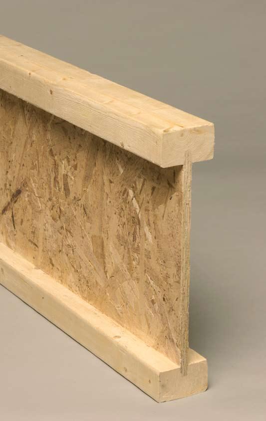
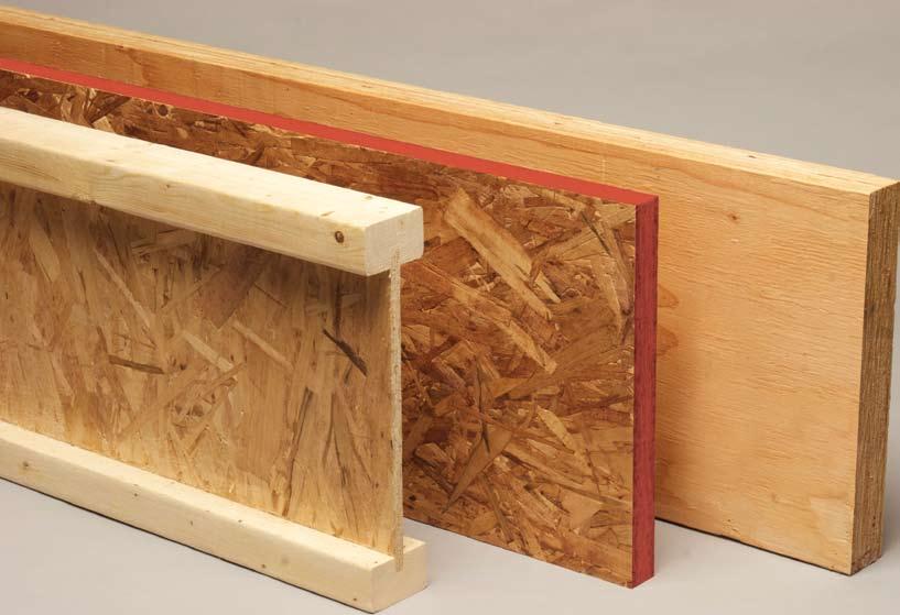
2 P A G E 1 I N T E R N A T I O N A L B E A M S Our Company At International Beams Inc. we take pride in providing our customers with premium quality products and services. Our full range of engineered wood products are manufactured to provide consistent, high performance floor and roof systems. Our technical staff consists of highly trained technical experts available to assist with any design or construction question and to provide full support for our design/layout software. Our Guarantee International Beams Inc. manufactures and tests its products to very high quality control standards. We are confident that our products will provide our customers with consistent high performance when handled and installed in accordance with our Installation Guide. We guarantee that our products are defect-free and capable of supporting loads as specified in our product literature for the life of the structure. In the unlikely event that you receive a product that has a manufacturer's defect, please contact us to have the problem remedied immediately. International Beams I-joists are made from two wood products. The flanges are made from small dimension lumber that is sawn from small trees and the tops of larger trees. Construction details reprinted with permission from the APA - The Engineered Wood Association. Table of Contents Our Company 1 Engineered Wood Products 2 Table 1, IB Commercial Product Line 3 Table 1A, Additional ER & IR 4 Table 2, 50LL+15+20DL Floor Span Table (NO web stiffeners) 5 Table 2A. 50LL+15+20DL Floor Span Table (WITH wen stiffeners) 6 Table 3, 100LL+15+20DL Floor Span Table (WITH web stiffeners) 7 Floor Framing & Construction Details 8 Floor Framing Details 9 Floor Framing Details 10 Web Stiffener Requirements 11 Cantilever Framing Details 12 Cantilever Framing & Double I-Joists Details 13 Web Hole Guidelines 14 Fire and Sound Rated Floor Assemblies 15 Roof Framing & Construction Details 16 Roof Framing Details 17 Roof Framing Details 18 Maximum Commercial Roof Spans 19 The Green Building Solution 20 Framing Connectors 21 Storage, Handling & Safety Guidelines 22 Environmental Choice In choosing wood as a construction material, The web is a special grade of oriented strand- When considering total environmental you are choosing the only building material board that is made from under-utilized wood impact including extraction of raw materials, that is made from renewable resources. Due species. Both components assist in achieving energy required during manufacturing, to sustained forest practices, the volume of total utilization of each tree harvested. emissions from manufacturing operations, wood in our forests has actually increased by and energy efficiency of buildings, International 35% over the last 25 years. Beams group of engineered wood products are among the most environmentally friendly building products available. For details on how IB products can help to meet green building standards, see page 20, or contact International Beams.


3 Engineered wood products, and specifically I-joists offer advantages over conventional lumber products that result in savings for the builder and long-term performance benefits for the homeowner. I-joists are installed using traditional framing tools and fasteners. With long lengths, I-joists are used in multiple span applications, thus reducing cutting, overlapping and material waste at the job site. Also, since I-joists span longer distances than traditional framing lumber, the joist spacing can be wider, resulting in fewer pieces to handle and install. The wide flanges used in all IB series provide a larger gluing and nailing surface for floor and roof sheathing. These lightweight joists will not twist, warp, or shrink and are more uniform in their dimensions than solid lumber. Our joists are available in depthts from 9½" to 24" and lengths up to 52 feets. For depths less than, see our Residential Design Manual or contact International Beams. International Beams Inc. s I-joists are recognized as an innovative solution to the building industry s floor and roof framing needs. Floor Performance Our broad range of I-joists provides the builder with flexibility in joist selection, spacing, and construction detail. Although all values contained in this brochure meet or exceed code requirements, long-term floor performance (comfort) should be considered in all construction projects. The following suggestions will increase the floor stiffness and reduce floor vibration: Using floor deflection of L/480 instead of the code minimum of L/360. Gluing and nailing the sub-floor to the joists. Attaching gypsum board to the bottom of the floor. Decreasing the joist spacing by one increment based on allowable span. Using full depth I-joist blocking panels at mid span between floor joists. Using deeper joists. Using a thicker sub-floor, i.e. ¾" or 7/8". Attaching strapping at 16" o/c. Design Services Design and related services include, but are not limited to: Beam sizing Component Framing Layouts Coordination with architects and builders On-site review Pricing Shipping These services are generally provided by your local International Beams distributor. There are also local lumber yards, stocking dealers, and design professionals who are familiar with our IB products and may be able to provide some of these design services. If you need help with your design project, please contact International Beams at sales@internationalbeams.com, or contact the local distributor indicated on the back cover of this literature. Engineering Responsibility Position Statement International Beams Inc. manufactures and distributes proprietary engineered wood products (EWP). We have full-time professional engineers (P.Eng.) on staff. Our engineers are active in the development, manufacture, and marketing of IB products. Our engineering services are limited to supporting the engineered wood components that we manufacture and distribute (IB I-joists, IB LVL, IB Rim Board). We review and seal component calculations produced on our software, and provide advice on proper installation. The design professional of record (P.Eng. or Architect) is responsible for design of the overall structure, global lateral stability, and interaction of various components of the structure. The limited scope of engineering services provided by International Beams Inc. does not replace the need on any project for a design professional of record.
4 P A G E 3 I N T E R N A T I O N A L B E A M S International Beams Product Line IB 600 IB 800 IB " 24" Engineering Properties of "600, 800, 900 Series Commercial Depth I-Joists" (Limit States Design) (A) Series IB600 IB800 IB900 Depth (in.) Bending Stiffness (B) EI joist (x10 6 psi) Factored Moment Resistance (C) M r (ft-lbs) Factored Shear Resistance (D) V r (lbs) Factored ER (E) Resistance 1 3/4 in. brg. (lbs) Factored IR (F) Resistance 3 1/2 in. brg. (lbs) Shear Deflection Factor (G) K (x10 6 psi) I-Joist Self- Weight (unfactored) (plf) 18 1,046 13,127 2,446 2,312 3, ,304 14,523 2,446 2,446 3, ,445 18,514 2,525 2,312 4, ,799 20,583 2,604 2,446 4, ,565 23,751 2,975 2,312 5, ,984 26,287 2,975 2,446 5, ,457 28,798 2,975 2,320 5, ,985 31,274 2,975 2,320 5, Notes: A. Design values were developed in accordance with CAN/CSA , "Engineering Design in Wood," for standard term load duration (KD=1). All values, except EI and K, are permitted to be adjusted for other load durations as permitted by CAN/CSA , "Engineering Design in Wood". B. Bending stiffness (EI) of the I-joist. C. Factored moment resistance (MR) shall not be increased by any Code-allowed system factor. D. Factored shear resistance (VR) of the I-joist with a minimum end bearing of 4 inches with web stiffeners. I-Joists without web stiffeners and reactionlimited smaller bearings may have lower capacities. See table 2 for web stiffener requirements which vary by depth and series. E. Factored end reaction (ER) resistance is for a minimum end bearing of 1 3/4" without web stiffeners. Higher end reactions are permitted with increased bearing length and web stiffeners. See table 2 for web stiffener requirements which vary by depth and series. F. Factored intermediate reaction (IR) resistance is for a minimum bearing length of 3 1/2 inches without web stiffeners. Higher interior reactions are permitted with increased bearing length and web stiffeners. See the factored end reaction table in this brochure for web stiffener requirements which vary by depth and series. G. Shear deflection factor (K), which shall be used to calculate uniform load and center-point load deflections of the I-joist in a simple span application based on equations #1 and #2 below. Equation #1 = 5wL 4 + wl 2 Where: (Uniform Load) 384EI K = Calculated deflection (inches) w = Unfactored uniform load (lbf/inch) Equation #2 = PL 3 + 2PL L = Design span (inches) (Center-Point Load) 48EI K EI = Bending stiffness of the I-joist (lbf-in.2) K = Shear deflection factor P = Concentrated load (lbf) H. For information relating to the use of International Beams products in the USA, refer to our American literature. CCMC R
5 I N T E R N A T I O N A L B E A M S P A G E 4 International Beams Product Line Factored End Reaction (ER) Resistances and Factored Interior Reactions (IR) Resistances of "600, 800, 900" Series Commercial Depth I-Joists (Limit States Design) (1) Series IB600 IB800 IB900 Factored End Reaction Resistance (2) (pounds) Factored Interior Reaction Resistance (3) (pounds) Depth (in.) 1¾" Bearing 3½" Bearing 4" Bearing 3½" Bearing 5½" Bearing No stiffeners Stiffeners No stiffeners Stiffeners No stiffeners Stiffeners No stiffeners Stiffeners No stiffeners Stiffeners 18 2,312 2,723 2,446 3,551 2,446 3,551 3,946 5,406 4,893 5, ,446 2,723 2,446 3,946 2,446 3,946 3,946 5,445 4,893 6, ,312 3,583 2,446 3,630 2,525 3,630 4,893 6,669 4,893 6, ,446 3,883 2,446 4,104 2,604 4,104 4,893 6,866 4,893 6, ,312 3,583 2,644 3,962 2,975 3,962 5,295 6,740 5,295 7, ,446 3,898 2,644 4,230 2,975 4,254 5,295 7,260 5,295 7, ,320 4,096 2,644 4,451 2,975 4,538 5,295 7,813 5,295 8, ,320 4,546 2,644 4,672 2,975 4,830 5,295 8,128 5,295 8,128 Notes: 1. Design values were developed in accordance with CAN/CSA , "Engineering Design in Wood", for standard term load duration (KD=1). All values, except EI and K, are permitted to be adjusted for other load durations as permitted by CAN/CSA , "Engineering Design in Wood". 2. Interpolation of the factored end reaction resistances between 1¾" and 3½" is permitted. 3. Interpolation of the factored interior reaction resistances between 3½" and 5½" is permitted.
6 P A G E 5 I N T E R N A T I O N A L B E A M S IB600, IB800 and IB900 Series Spans Table 2 - IB600, IB800 and IB900 Maximum Floor Spans 50 psf Unfactored Live Load 15 psf Unfactored Material Weight + 20 psf Unfactored Partition Dead Load (for a total of 35 psf Unfactored Dead Load) Limit States Design (LSD) 100% Load Duration (L/480 live load, L/240 total load deflection criteria) Series IB600 IB800 IB900 Depth 22" 24" I-Joist Floor Assembly Span 1¾" 1¾" Span Indicated in Table 5/8" OSB subfloor glued and nailed Spacing of IB joist (o.c.) 1¾" 3½" 1¾" Span 1 CL of interior bearing Span 2 Spans Indicated in Table Legend Assembly : Indicated subfloor only - NO vibration analysis Assembly : Indicated subfloor only CCMC vibration analysis applied Assembly : Indicated subfloor with one row of mid-span I-joist blocking CCMC vibration analysis applied Subfloor 3/4" OSB subfloor glued and nailed Spacing of IB joist (o.c.) 7/8" OSB subfloor glued and nailed Spacing of IB joist (o.c.) 12" 16" 19.2" 12" 16" 19.2" 24" 12" 16" 19.2" 24" 28'-5" 24'-1" 30'-7" 28'-4" 31'-4" 24'-7" 26'-11" 23'-8" 26'-4" 28'-6" 23'-4" 21'-3" 23'-4" 24'-7" 22'-8" 24'-7" 28'-6" 25'-8" 27'-8" 30'-9" 27'-3" 29'-7" 31'-6" 23'-9" 26'-11" 25'-3" 26'-11" 28'-7" 23'-4" 22'-7" 23'-4" 24'-7" 24'-1" 24'-7" 16'-5" 28'-8" 27'-0" 28'-9" 30'-11" 28'-9" 30'-8" 31'-8" 26'-11" 26'-11" 28'-9" 23'-4" 23'-4" 23'-4" 24'-7" 24'-7" 24'-7" 16'-5" 25'-10" 28'-9" 28'-5" 32'-2" 33'-9" 27'-6" 30'-7" 30'-4" 32'-4" 29'-5" 29'-0" 33'-1" 35'-0" 28'-4" 31'-5" 31'-2" 37'-7" 30'-1" 33'-11" 33'-9" 38'-11" 31'-10" 36'-8" 23'-10" 26'-3" 30'-8" 25'-5" 28'-1" 29'-1" 24'-6" 26'11" 30'-9" 26'-2" 29'-8" 28'-10" 27'-9" 22'-9" 20-'6" 23'-4" 24'-11" 27'-7" 30'-7" 29'-8" 33'-11" 29'-4" 32'-8" 31'-8" 32'-5" 28'-3" 31'-3" 30'-4" 34'-11" 35'-1" 30'-2" 33'-11" 32'-9" 37'-8" 32'-1" 35'-9" 38'-11" 34'-6" 38'-8" 25'-5" 27'-6" 30'-9" 27'-1" 29'-5" 29'-1" 26'-1" 28'-2" 30'-9" 27'-10" 30'-2" 16'-5" 16'-5" 16'-5" 16'-5" 16'-5" 19'-5" 19'-5" 19'-5" 19'-5" 19'-5" 19'-5" 29'-0" 32'-2" 30'-9" 34'-0" 30'-10" 33'-2" 32'-7" 29'-8" 33'-2" 31'-5" 35'-3" 31'-9" 34'-4" 37'-10" 34'-3" 37'-5" 38'-11" 36'-10" 38'-11" 26'-10" 28'-8" 30'-9" 28'-7" 30'-7" 29'-1" 27'-6" 29'-1" 30'-9" 29'-4" 30'-9" 16'-5" 16'-5" 16'-5" 16'-5" 16'-5" 19'-5" 19'-5" 19'-5" 19'-5" 19'-5" 19'-5" NOTES: (a) Allowable spans are applicable to floor construction. LSD load factor of 1.5 is applied to live load and 1.25 to dead load for strength calculations. If partition dead load is not required, the total design dead load of 35 psf may be used for material weight of the floor construction. (b) Allowable spans have been calculated with the CCMC vibration criteria limits only where indicated in the assembly. (c) Deflection limits indicated in the table heading are based on partial composite action with glued and nailed subfloor meeting requirements for APA Span-Rated STURD-I-FLOOR conforming to PRP-108, PS 1, PS 2, CSA 0325, or CSA Construction adhesive shall meet the requirements given in ASTM D3498 or APA Specification AFG-01. (d) Minimum bearing length shall be 1¾ for end bearing and 3 ½ for interior bearings. Allowable design spans in the table are measured from inside face of bearings for simple spans and from inside face of end bearing to center of interior bearing for continuous spans. (e) Bearing stiffeners are not required when I-joists are used with the spans given in this table, except as required by hanger manufacturers. (f) This span table is based on uniform loads. For applications with other than uniformly distributed loads, or other applications beyond the scope of the indicated design criteria, an engineering analysis may be required based on the use of the design properties accepted in the CCMC R evaluation report. Design properties are also indicated in table 1 at the front of the design manual. For technical support, contact International Beams (IB) or your local IB distributor. (g) spans given in the table above are the longest clearspan between bearings for a joist with three bearings. The ratio of the shorter span to the longer spans must be greater than 40%. For two spans with a ratio of between 40% and 76%, provide metal hangers or equivalent to withstand an uplift force at the end of the shorter span. Calculate uplift at the end of the shorter span as follows: factored total load (psf) x joist spacing (inches) x [(shorter span (feet) minus 0.76 x longer span (feet)] divided by 25. For all other applications, consult International Beams.
7 I N T E R N A T I O N A L B E A M S P A G E 6 IB600, IB800 and IB900 Series Spans Table 2A - IB600, IB800 and IB900 Maximum Floor Spans 50 psf Unfactored Live Load 15 psf Unfactored Material Weight + 20 psf Unfactored Partition Dead Load (for a total of 35 psf Unfactored Dead Load) Limit States Design (LSD) 100% Load Duration (L/480 live load, L/240 total load deflection criteria) Series IB600 IB800 IB900 Depth 22" 24" I-Joist Floor Assembly Span 3½" Bearings WITH Bearing Stiffeners 3½" 3½" Span Indicated in Table 5/8" OSB subfloor glued and nailed Spacing of IB joist (o.c.) 3½" 3½" 3½" Span 1 CL of interior bearing Span 2 Spans Indicated in Table Legend Assembly : Indicated subfloor only - NO vibration analysis Assembly : Indicated subfloor only CCMC vibration analysis applied Assembly : Indicated subfloor with one row of mid-span I-joist blocking CCMC vibration analysis applied Subfloor 3/4" OSB subfloor glued and nailed Spacing of IB joist (o.c.) 7/8" OSB subfloor glued and nailed Spacing of IB joist (o.c.) 12" 16" 19.2" 12" 16" 19.2" 24" 12" 16" 19.2" 24" 28'-04" 25'-06" 23'-03" 28'-05" 25'-06" 23'-03" 20'-09" 28'-07" 25'-06" 23'-03" 20'-09" 29'-07" 25'-07" 22'-07" 29'-07" 25'-07" 22'-07" 18'-01" 29'-07" 25'-07" 22'-07" 18'-01" 23'-11" 22'-01" 21'-02" 25'-06" 23'-07" 22'-05" 20'-09" 26'-10" 24'-11" 23'-03" 20'-09" 26'-07" 24'-08" 22'-07" 28'-04" 25'-07" 22'-07" 18'-01" 29'-07" 25'-07" 22'-07" 18'-01" 26'-04" 24'-05" 23'-03" 27'-06" 25'-06" 23'-03" 20'-09" 28'-07" 25'-06" 23'-03" 20'-09" 29'-01" 25'-07" 22'-07" 29'-07" 25'-07" 22'-07" 18'-01" 29'-07" 25'-07" 22'-07" 18'-01" 30'-06" 26'-10" 24'-05" 30'-07" 26'-10" 24'-05" 21'-10" 30'-10" 26'-10" 24'-05" 21'-10" 31'-02" 26'-11" 22'-09" 31'-02" 26'-11" 22'-09" 18'-02" 31'-02" 26'-11" 22'-09" 18'-02" 25'-06" 23'-07" 22'-06" 27'-02" 25'-01" 23'-11" 21'-10" 28'-07" 26'-06" 24'-05" 21'-10" 28'-04" 26'-03" 22'-09" 30'-02" 26'-11" 22'-09" 18'-02" 31'-02" 26'-11" 22'-09" 18'-02" 28'-03" 26'-02" 24'-05" 29'-05" 26'-10" 24'-05" 21'-10" 30'-07" 26'-10" 24'-05" 21'-10" 31'-02" 26'-11" 22'-09" 31'-02" 26'-11" 22'-09" 18'-02" 31'-02" 26'-11" 22'-09" 18'-02" 31'-03" 28'-04" 26'-08" 31'-04" 28'-05" 26'-09" 24'-08" 31'-06" 28'-08" 26'-11" 24'-08" 35'-02" 30'-05" 27'-09" 35'-02" 30'-05" 27'-09" 22'-04" 35'-02" 30'-05" 27'-09" 22'-04" 25'-09" 23'-09" 22'-08" 27'-05" 25'-03" 24'-00" 22'-08" 28'-10" 26'-08" 25'-04" 23'-10" 28'-08" 26'-06" 25'-03" 30'-06" 28'-02" 26'-10" 22'-04" 32'-01" 29'-09" 27'-09" 22'-04" 28'-03" 26'-02" 24'-11" 29'-06" 27'-05" 26'-01" 24'-08" 30'-07" 28'-06" 26'-11" 24'-08" 31'-03" 28'-11" 27'-07" 30'-04" 27'-09" 22'-04" 34'-07" 30'-05" 27'-09" 22'-04" 33'-08" 30'-07" 28'-09" 33'-09" 30'-08" 28'-10" 26'-01" 33'-11" 30'-10" 29'-00" 26'-01" 37'-01" 32'-01" 28'-09" 37'-01" 32'-01" 28'-09" 23'-00" 37'-01" 32'-01" 28'-09" 23'-00" 27'-05" 25'-03" 24'-01" 29'-02" 26'-11" 25'-07" 24'-02" 30'-09" 28'-05" 27'-00" 25'-05" 30'-06" 28'-02" 26'-10" 32'-07" 30'-00" 28'-06" 23'-00" 34'-11" 31'-07" 28'-09" 23'-00" 30'-03" 28'-00" 26'-08" 31'-07" 29'-03" 27'-11" 26'-01" 33'-00" 30'-05" 29'-00" 26'-01" 33'-11" 30'-11" 28'-09" 36'-00" 32'-01" 28'-09" 23'-00" 37'-01" 32'-01" 28'-09" 23'-00" 32'-03" 29'-03" 27'-06" 32'-04" 29'-04" 27'-07" 25'-08" 32'-05" 29'-06" 27'-10" 25'-10" 36'-06" 33'-00" 28'-03" 36'-07" 33'-01" 28'-03" 22'-07" 36'-09" 33'-03" 28'-03" 22'-07" 26'-04" 24'-04" 23'-02" 28'-01" 25'-11" 24'-08" 23'-03" 29'-06" 27'-04" 26'-00" 24'-05" 29'-04" 27'-01" 25'-10" 31'-02" 28'-10" 27'-05" 22'-07" 33'-01" 30'-05" 28'-03" 22'-07" 28'-11" 26'-09" 25'-06" 30'-02" 28'-00" 26'-08" 25'-02" 31'-04" 29'-02" 27'-09" 25'-10" 31'-11" 29'-07" 28'-03" 33'-10" 31'-00" 28'-03" 22'-07" 35'-06" 32'-04" 28'-03" 22'-07" 34'-11" 31'-08" 29'-10" 35'-00" 31'-09" 29'-11" 27'-09" 35'-02" 32'-00" 30'-01" 28'-00" 41'-11" 36'-04" 30'-05" 41'-11" 36'-04" 30'-05" 24'-04" 41'-11" 36'-04" 30'-05" 24'-04" 28'-02" 26'-00" 24'-10" 30'-00" 27'-08" 26'-04" 24'-10" 31'-07" 29'-02" 27'-09" 26'-01" 31'-05" 29'-00" 27'-08" 33'-10" 30'-10" 29'-04" 24'-04" 36'-02" 32'-08" 30'-05" 24'-04" 31'-00" 28'-09" 27'-05" 32'-07" 30'-01" 28'-07" 27'-00" 34'-02" 31'-03" 29'-09" 28'-00" 35'-02" 31'-09" 30'-04" 37'-03" 33'-08" 30'-05" 24'-04" 39'-00" 35'-06" 30'-05" 24'-04" 37'-06" 34'-00" 32'-00" 37'-07" 34'-02" 32'-02" 29'-10" 37'-09" 34'-04" 32'-04" 30'-01" 43'-11" 38'-00" 32'-09" 43'-11" 38'-00" 32'-09" 26'-02" 43'-11" 38'-00" 32'-09" 26'-02" 30'-00" 27'-08" 26'-04" 31'-11" 29'-05" 27'-11" 26'-05" 34'-01" 31'-00" 29'-06" 27'-08" 33'-10" 30'-09" 29'-04" 36'-08" 33'-00" 31'-01" 26'-02" 39'-01" 35'-04" 32'-09" 26'-02" 33'-08" 30'-08" 29'-03" 35'-07" 32'-02" 30'-06" 28'-10" 37'-03" 33'-10" 31'-09" 29'-10" 38'-05" 34'-07" 32'-05" 40'-07" 36'-09" 32'-09" 26'-02" 42'-05" 38'-00" 32'-09" 26'-02" 40'-00" 36'-04" 34'-02" 40'-02" 36'-06" 34'-04" 31'-10" 40'-04" 36'-08" 34'-06" 32'-01" 45'-09" 39'-07" 34'-01" 45'-09" 39'-07" 34'-01" 27'-03" 45'-09" 39'-07" 34'-01" 27'-03" 31'-08" 29'-02" 27'-10" 34'-04" 31'-01" 29'-06" 27'-10" 36'-08" 33'-01" 31'-01" 29'-03" 36'-05" 32'-08" 31'-00" 39'-05" 35'-06" 33'-02" 27'-03" 42'-00" 38'-00" 34'-01" 27'-03" 36'-06" 32'-10" 31'-00" 38'-06" 34'-10" 32'-07" 30'-06" 40'-03" 36'-08" 34'-04" 31'-08" 41'-08" 37'-06" 34'-01" 43'-11" 39'-07" 34'-01" 27'-03" 45'-09" 39'-07" 34'-01" 27'-03" NOTES: (a) Allowable spans are applicable to floor construction. LSD load factor of 1.5 is applied to live load and 1.25 to dead load for strength calculations. If partition dead load is not required, the total design dead load of 35 psf may be used for material weight of the floor construction. (b) Allowable spans have been calculated with the CCMC vibration criteria limits only where indicated in the assembly. (c) Deflection limits indicated in the table heading are based on partial composite action with glued and nailed subfloor meeting requirements for APA Span-Rated STURD-I-FLOOR conforming to PRP-108, PS 1, PS 2, CSA 0325, or CSA Construction adhesive shall meet the requirements given in ASTM D3498 or APA Specification AFG-01. (d) Minimum bearing length shall be 3½" for end bearing and 3 ½ for interior bearings. Allowable design spans in the table are measured from inside face of bearings for simple spans and from inside face of end bearing to center of interior bearing for continuous spans. (e) Bearing stiffeners are required when I-joists are used with the spans given in this table. (f) This span table is based on uniform loads. For applications with other than uniformly distributed loads, or other applications beyond the scope of the indicated design criteria, an engineering analysis may be required based on the use of the design properties accepted in the CCMC R evaluation report. Design properties are also indicated in table 1 at the front of the design manual. For technical support, contact International Beams (IB) or your local IB distributor. (g) spans given in the table above are the longest clearspan between bearings for a joist with three bearings. The ratio of the shorter span to the longer spans must be greater than 40%. For two spans with a ratio of between 40% and 76%, provide metal hangers or equivalent to withstand an uplift force at the end of the shorter span. Calculate uplift at the end of the shorter span as follows: factored total load (psf) x joist spacing (inches) x [(shorter span (feet) minus 0.76 x longer span (feet)] divided by 25. For all other applications, consult International Beams.
8 P A G E 7 I N T E R N A T I O N A L B E A M S IB600, IB800 and IB900 Series Spans Table 3 - IB600, IB800 and IB900 Maximum Floor Spans 100 psf Unfactored Live Load 15 psf Unfactored Material Weight + 20 psf Unfactored Partition Dead Load (for a total of 35 psf Unfactored Dead Load) Limit States Design (LSD) 100% Load Duration (L/480 live load, L/240 total load deflection criteria) Series IB600 IB800 IB900 Depth 22" 24" I-Joist Floor Assembly Span 3½" Bearings WITH Bearing Stiffeners 3½" 3½" Span Indicated in Table 5/8" OSB subfloor glued and nailed Spacing of IB joist (o.c.) 22'-01" 22'-02" 22'-01" 22'-02" 22'-01" 22'-02" 23'-09" 22'-04" 23'-09" 22'-04" 23'-09" 22'-04" 24'-04" 27'-05" 24'-04" 27'-05" 24'-04" 27'-05" 26'-03" 28'-02" 26'-03" 28'-02" 26'-03" 28'-02" 25'-02" 27'-08" 25'-02" 27'-08" 25'-02" 27'-08" 27'-03" 29'-10" 27'-03" 29'-10" 27'-03" 29'-10" 29'-04" 32'-01" 29'-04" 32'-01" 29'-04" 32'-01" 31'-04" 33'-05" 31'-04" 33'-05" 31'-04" 33'-05" 3½" 3½" 3½" Span 1 CL of interior bearing Span 2 Spans Indicated in Table Legend Assembly : Indicated subfloor only - NO vibration analysis Assembly : Indicated subfloor only CCMC vibration analysis applied Assembly : Indicated subfloor with one row of mid-span I-joist blocking CCMC vibration analysis applied Subfloor 3/4" OSB subfloor glued and nailed Spacing of IB joist (o.c.) 7/8" OSB subfloor glued and nailed Spacing of IB joist (o.c.) 12" 16" 19.2" 12" 16" 19.2" 24" 12" 16" 19.2" 24" 18'-01" 22'-02" 18'-01" 16'-02" 22'-03" 18'-01" 16'-07" 13'-10" 22'-02" 16'-07" 13'-10" 11'-00" 22'-02" 16'-07" 13'-10" 18'-01" 22'-02" 18'-01" 16'-02" 22'-03" 18'-01" 16'-07" 13'-10" 22'-02" 16'-07" 13'-10" 11'-00" 22'-02" 16'-07" 13'-10" 18'-01" 22'-02" 18'-01" 16'-02" 22'-03" 18'-01" 16'-07" 13'-10" 22'-02" 16'-07" 13'-10" 11'-00" 22'-02" 16'-07" 13'-10" 20'-11" 19'-01" 23'-10" 20'-11" 19'-01" 17'-00" 24'-00" 20'-11" 19'-01" 16'-09" 13'-11" 22'-04" 16'-09" 13'-11" 11'-01" 22'-04" 16'-09" 13'-11" 20'-11" 19'-01" 23'-10" 20'-11" 19'-01" 17'-00" 24'-00" 20'-11" 19'-01" 16'-09" 13'-11" 22'-04" 16'-09" 13'-11" 11'-01" 22'-04" 16'-09" 13'-11" 20'-11" 19'-01" 23'-10" 20'-11" 19'-01" 17'-00" 24'-00" 20'-11" 19'-01" 16'-09" 13'-11" 22'-04" 16'-09" 13'-11" 11'-01" 22'-04" 16'-09" 13'-11" 22'-00" 20'-07" 24'-05" 22'-01" 20'-08" 18'-05" 24'-06" 22'-02" 20'-10" 20'-06" 17'-01" 27'-05" 20'-06" 17'-01" 13'-07" 27'-05" 20'-06" 17'-01" 22'-00" 20'-07" 24'-05" 22'-01" 20'-08" 18'-05" 24'-06" 22'-02" 20'-10" 20'-06" 17'-01" 27'-05" 20'-06" 17'-01" 13'-07" 27'-05" 20'-06" 17'-01" 22'-00" 20'-07" 24'-05" 22'-01" 20'-08" 18'-05" 24'-06" 22'-02" 20'-10" 20'-06" 17'-01" 27'-05" 20'-06" 17'-01" 13'-07" 27'-05" 20'-06" 17'-01" 23'-08" 22'-03" 26'-04" 23'-09" 22'-04" 20'-04" 26'-05" 23'-11" 22'-05" 21'-01" 17'-07" 28'-02" 21'-01" 17'-07" 14'-00" 28'-02" 21'-01" 17'-07" 23'-08" 22'-03" 26'-04" 23'-09" 22'-04" 20'-04" 26'-05" 23'-11" 22'-05" 21'-01" 17'-07" 28'-02" 21'-01" 17'-07" 14'-00" 28'-02" 21'-01" 17'-07" 23'-08" 22'-03" 26'-04" 23'-09" 22'-04" 20'-04" 26'-05" 23'-11" 22'-05" 21'-01" 17'-07" 28'-02" 21'-01" 17'-07" 14'-00" 28'-02" 21'-01" 17'-07" 22'-09" 21'-04" 25'-03" 22'-10" 21'-05" 25'-04" 23'-00" 21'-07" 20'-09" 17'-03" 27'-08" 20'-09" 17'-03" 13'-09" 27'-08" 20'-09" 17'-03" 22'-09" 21'-04" 25'-03" 22'-10" 21'-05" 25'-04" 23'-00" 21'-07" 20'-09" 17'-03" 27'-08" 20'-09" 17'-03" 13'-09" 27'-08" 20'-09" 17'-03" 22'-09" 21'-04" 25'-03" 22'-10" 21'-05" 25'-04" 23'-00" 21'-07" 20'-09" 17'-03" 27'-08" 20'-09" 17'-03" 13'-09" 27'-08" 20'-09" 17'-03" 24'-08" 23'-02" 27'-04" 24'-09" 23'-03" 21'-06" 27'-05" 24'-11" 23'-04" 22'-04" 18'-07" 29'-10" 22'-04" 18'-07" 14'-10" 29'-10" 22'-04" 18'-07" 24'-08" 23'-02" 27'-04" 24'-09" 23'-03" 21'-06" 27'-05" 24'-11" 23'-04" 22'-04" 18'-07" 29'-10" 22'-04" 18'-07" 14'-10" 29'-10" 22'-04" 18'-07" 24'-08" 23'-02" 27'-04" 24'-09" 23'-03" 21'-06" 27'-05" 24'-11" 23'-04" 22'-04" 18'-07" 29'-10" 22'-04" 18'-07" 14'-10" 29'-10" 22'-04" 18'-07" 26'-06" 24'-11" 29'-05" 26'-07" 25'-00" 22'-08" 29'-06" 26'-09" 25'-02" 24'-01" 20'-00" 32'-01" 24'-01" 20'-00" 16'-00" 32'-01" 24'-01" 20'-00" 26'-06" 24'-11" 29'-05" 26'-07" 25'-00" 22'-08" 29'-06" 26'-09" 25'-02" 24'-01" 20'-00" 32'-01" 24'-01" 20'-00" 16'-00" 32'-01" 24'-01" 20'-00" 26'-06" 24'-11" 29'-05" 26'-07" 25'-00" 22'-08" 29'-06" 26'-09" 25'-02" 24'-01" 20'-00" 32'-01" 24'-01" 20'-00" 16'-00" 32'-01" 24'-01" 20'-00" 28'-04" 26'-07" 31'-04" 28'-05" 26'-08" 23'-10" 31'-06" 28'-07" 26'-10" 25'-00" 20'-10" 33'-05" 25'-00" 20'-10" 16'-08" 33'-05" 25'-00" 20'-10" 28'-04" 26'-07" 31'-04" 28'-05" 26'-08" 23'-10" 31'-06" 28'-07" 26'-10" 25'-00" 20'-10" 33'-05" 25'-00" 20'-10" 16'-08" 33'-05" 25'-00" 20'-10" 28'-04" 26'-07" 31'-04" 28'-05" 26'-08" 23'-10" 31'-06" 28'-07" 26'-10" 25'-00" 20'-10" 33'-05" 25'-00" 20'-10" 16'-08" 33'-05" 25'-00" 20'-10" 16'-02" 11'-00" 16'-02" 11'-00" 16'-02" 11'-00" 17'-00" 11'-01" 17'-00" 11'-01" 17'-00" 11'-01" 18'-05" 13'-07" 18'-05" 13'-07" 18'-05" 13'-07" 20'-04" 14'-00" 20'-04" 14'-00" 20'-04" 14'-00" 19'-11" 13'-09" 19'-11" 13'-09" 19'-11" 13'-09" 21'-06" 14'-10" 21'-06" 14'-10" 21'-06" 14'-10" 22'-08" 16'-00" 22'-08" 16'-00" 22'-08" 16'-00" 23'-10" 16'-08" 23'-10" 16'-08" 23'-10" 16'-08" NOTES: (a) Allowable spans are applicable to floor construction. LSD load factor of 1.5 is applied to live load and 1.25 to dead load for strength calculations. If partition dead load is not required, the total design dead load of 35 psf may be used for material weight of the floor construction. (b) Allowable spans have been calculated with the CCMC vibration criteria limits only where indicated in the assembly. (c) Deflection limits indicated in the table heading are based on partial composite action with glued and nailed subfloor meeting requirements for APA Span-Rated STURD-I-FLOOR conforming to PRP-108, PS 1, PS 2, CSA 0325, or CSA Construction adhesive shall meet the requirements given in ASTM D3498 or APA Specification AFG-01. (d) Minimum bearing length shall be 3½" for end bearing and 3 ½ for interior bearings. Allowable design spans in the table are measured from inside face of bearings for simple spans and from inside face of end bearing to center of interior bearing for continuous spans. (e) Bearing stiffeners are required when I-joists are used with the spans given in this table. (f) This span table is based on uniform loads. For applications with other than uniformly distributed loads, or other applications beyond the scope of the indicated design criteria, an engineering analysis may be required based on the use of the design properties accepted in the CCMC R evaluation report. Design properties are also indicated in table 1 at the front of the design manual. For technical support, contact International Beams (IB) or your local IB distributor. (g) spans given in the table above are the longest clearspan between bearings for a joist with three bearings. The ratio of the shorter span to the longer spans must be greater than 40%. For two spans with a ratio of between 40% and 76%, provide metal hangers or equivalent to withstand an uplift force at the end of the shorter span. Calculate uplift at the end of the shorter span as follows: factored total load (psf) x joist spacing (inches) x [(shorter span (feet) minus 0.76 x longer span (feet)] divided by 25. For all other applications, consult International Beams.
9 I N T E R N A T I O N A L B E A M S Floor Framing & Construction Details P A G E 8 Floor Framing and Construction Details Some framing requirements such as erection bracing and blocking panels have been omitted for clarity. 1D Glulam or multiple Structural Composite Lumber (SCL) headers 1E 1G Holes may be cut in web for plumbing, wiring and duct work. NOTE: Never cut or notch flanges. Glulam or multiple SCL headers 1B 1C Use code approved hangers 1J 1A 1N 1F 1H 1J 1K 1M Installation Notes 1. Before laying out floor system components, verify that IB I-joist flange widths match hanger widths. If not, contact your supplier. 2. Except for cutting to length, never cut, drill, or notch IB I-joist flanges. 3. Install IB I-joists so that top and bottom flanges are within ½ inch of true vertical alignment. 4. IB I-joists must be anchored securely to supports before floor sheathing is attached, and supports for multiple-span joists must be level. 5. Minimum bearing lengths: 1¾inches for end bearings and 3 ½ inches for intermediate bearings. 6. When using hangers, seat IB I-joists firmly in hanger bottoms to minimize settlement. 7. Leave a ¹ ₁₆ inch gap between the IB I-joist end and a header. 8. Concentrated loads greater than those that can normally be expected in residential construction should only be applied to the top surface of the top flange. Normal concentrated loads include track lighting fixtures, audio equipment and security cameras. Never suspend unusual or heavy loads from the IB I-joist s bottom flange. Whenever possible, suspend all concentrated loads from the top of the IB I-joist. Or, attach the load to blocking that has been securely fastened to the IB I-joist webs. 9. Never install IB I-joists where they will be permanently exposed to weather, or where they will remain in direct contact with concrete or masonry. 10. Restrain ends of floor joists to prevent rollover. Use rim board or equivalent, rim joists or IB I-joist blocking panels. 11. For IB I-joists installed over and beneath bearing walls, use full depth blocking panels, rim board, or squash blocks (cripple members) to transfer gravity loads through the floor system to the wall or foundation below. 12. Due to shrinkage, common framing lumber set on edge may never be used as blocking or rim boards. IB I-joist blocking panels or other engineered wood products such as rim board must be cut to fit between the IB I-joists, and an IB I-joistcompatible depth selected. 13. Provide permanent lateral support of the bottom flange of all IB I-joists at interior supports of multiple-span joists. Similarly, support the bottom flange of all cantilevered IB I-joists at the end support next to the cantilever extension. In the completed structure, the gypsum wallboard ceiling provides this lateral support. Until the final finished ceiling is applied, temporary bracing or struts must be used. 14. If square-edge panels are used, edges must be supported between IB I-joists with 2x4 blocking. Glue panels to blocking to minimize squeaks. Blocking is not required under structural finish flooring, such as wood strip flooring, or if a separate underlayment layer is installed. 15. Nail spacing: Space nails installed to the flange s top face in accordance with the applicable building code requirements or approved building plans. If nails must be installed into the sides of flanges, spacing shall not be closer than 3 inches o.c. for 8d common nails, and 4 inches o.c. for 10d common nails.
10 P A G E 9 Floor Framing Details I N T E R N A T I O N A L B E A M S Floor Framing and Construction Details All nails shown in the details below are assumed to be common nails unless otherwise noted. 10d box nails may be substituted for 8d common shown in details. Individual components not shown to scale for clarity. 1A Attach IB I-joist to top plate per 1B 1C Attach IB I-joist per 1B Attach rim joist to top plate per 1A 1E Blocking Panel or Rim Jost depth (inches) Rim joist vertical load transfer = 2000 plf maximum 1F Maximum Factored Uniform Vertical Load (plf) IB600 IB800 IB900 1⅛" IB OSB Rimboard Attach rim joist to floor joist with one nail at top and bottom. Nail must provide 1 inch minimum penetration into floor joist. Toe nails may be used. Minimum 1 ¾ " bearing required d 6" o.c. (when used for lateral shear transfer, nail to bearing plate with same nailing as required for decking) 1D 1B Use single IB I-joist for loads up to 2000 plf, double I-joists for loads up to 4000 plf (filler block not required). One 8d face nail at each side at bearing Squash block Provide lateral bracing per 1A, 1B, or 1C 1G For APA Rimboard Plus, 1⅛" thick, up to 24" depth allowable factored vertical load transfer = 8090 plf. One 8d nail at top and bottom flange Attach rim board to top plate using 8d box 6" o.c. To avoid splitting flange, start nails at least 1 ½" from end of IB I-joist. Nails may be driven at an angle to avoid splitting of bearing plate. Rim board blocking panel per 1a Joist attachment per detail 1B 1 16 " for lumber squash blocks Vertical load transfer capacity per pair of squash blocks as shown: Maximum factored vertical load per pair of squash blocks (lb) Pair of Squash Blocks 2x Lumber 1⅛" APA Rim board, Rim Board Plus, or Rated Sturd-I-Floor 48 oc 1" APA Rim Board or Rated Sturd-I-Floor 32 oc Load bearing wall above shall align vertically with the wall below. Other conditions such as offset walls are not covered by this detail. 3½" wide 5½" wide Blocking required over all interior supports Transfer load from above to bearing below. Install squash blocks per 1D. Match bearing area of blocks below to post above. Wall sheathing, as required Rim board may be used in lieu of IB I-joists. Backer is not required when rim board is used. Provide backer for siding attachment unless nailable sheathing is used. 8d nails at 6" o.c. Blocking panel for vertical load transfer capacity, see detail 1A
11 I N T E R N A T I O N A L B E A M S Floor Framing Details P A G E 1 0 Floor Framing and Construction Details All nails shown in the details below are assumed to be common nails unless otherwise noted. 10d box nails may be substituted for 8d common shown in details. Individual components not shown to scale for clarity. 1H Backer block (use if factored hanger load exceeds 360 lbs.) Before installing a backer block to a double I-joist, drive 3 additional 3" nails through the webs and filler block where the backer block will fit. Clinch. Install backer tight to top flange. Use twelve 3" nails, clinched when possible. Maximum factored resistance for hanger for this detail = 1620 lbs. Backer blocks (Blocks must be long enough to permit required nailing without splitting) Flange Width Material Thickness Required* Minimum Depth** 2 ½ " 1" 5 ½" 3 ½ " 1 ½ " 7 ¼" Top- or face-mounted hanger Double IB I-joist header Note: Unless hanger sides laterally support the top flange, bearing stiffeners shall be used. * Minimum grade for backer block material shall be Utility grade SPF (south) or better for solid sawn lumber and Rated Sheathing grade for wood structural panels. ** For face-mount hangers use net joist depth minus 3-1/4". Filler block Backer block required (both sides for face-mounted hangers) For hanger capacity see hanger manufacturer s recommendations. Verify double IB I-joist capacity to support concentrated loads. 1J Glulam or multiple structural composite lumber (SCL) beams 1K 2x plate flush with inside face of wall or beam For nailing schedules for multiple SCL beams, see the manufacturer s recommendations Top- or face-mounted hanger installed per manufacturer s recommendations Note: Unless hanger sides laterally support the top flange, bearing stiffeners shall be used. Top-mounted hanger installed per manufacturer s recommendations Note: Unless hanger sides laterally support the top flange, bearing stiffeners shall be used. 1M Install framing anchor per manufacturer s recommendations (both sides of stringer) Maximum factored support = 1620 lbs Filler block Multiple IB I-joist header with full depth filler block shown. Glulam and multiple SCL headers may also be used. Verify double IB I-joist capacity to support concentrated loads. Backer block attach per 1H. Nail with twelve 10d nails, clinch when possible. 1N Note: Blocking required at bearing for lateral support, not shown for clarity. Do not bevelcut joist beyond inside face of wall Attach IB I-joist per 1B
12 P A G E 1 1 Web Stiffener Requirements I N T E R N A T I O N A L B E A M S A web stiffener is a wood block that is used to reinforce the web of an IB I-joist at locations where: The webs of the IB I-joists are in jeopardy of buckling out of plane. This usually occurs in deeper IB I-joists. The webs of the IB I-joist are in jeopardy of knifing through the IB I-joist flanges. This can occur at any IB I-joist depth when the design reaction loads exceed a specific level. The IB I-joist is supported in a hanger and the sides of the hanger do not extend up to the top flange. With the top flange unsupported by the hanger sides, the joist may deflect laterally, putting a twist in the flange of the joist. The web stiffener supports the IB I-joist along a vertical axis as designed. (In this application, the web stiffener acts very much like a backer block.) There are two kinds of web stiffeners: bearing stiffeners and load stiffeners. They are differentiated by the applied load and location of the gap between the slightly undersized stiffener and the top or bottom flange. Bearing stiffeners are located at the reactions, both interior and exterior, when required. IB I-joists do not need bearing stiffeners at any support when subjected to normal residential form loads and installed in accordance with the allowable spans. Load stiffeners are located between supports where significant point loads are applied to the top flange of an IB I- joist. Web stiffener blocks may be comprised of lumber, rim board, or structural wood panels. The minimum grade of structural wood panels is Rated Sheathing; minimum lumber grade is Utility grade SPF (south) or better. Any rim board product would also work satisfactorily. Ideally, the depth of the web stiffener should equal the distance between the flanges of the joist minus ⅛ inch - ¼ inch. For bearing stiffeners, this gap is placed between the stiffener and the bottom of the top flange. For load stiffeners, the gap is located at the bottom of the stiffener. 1. A bearing stiffener is required in all engineered applications which exceed the "no stiffeners" factored reaction resistances indicated in table 1A on page 4. The gapbetween the stiffener and the flange is atthe top. 2. A load stiffener is required at locations where a concentrated load greater than 1500 lb. unfactored load is applied to the top flange between supports, or in the case of acantilever, anywhere between the cantilever tip and the support. The gap between the stiffener and the flange is at the bottom. 3. A bearing stiffener is required when the IB I-joist is supported in a hanger and the sides of the hanger do not extend up to, and support, the top flange. The gap between the stiffener and flange is at top. Web Stiffener Requirements Flange width 2½ " or 3½ " Tight Joint No Gap Concentrated Load (Load stiffener) End Bearing (Bearing stiffener) Gap ±2" ±2" ⅛"-¼" Gap use minimum of (6) 8d nails 10d nails required for IB I-joists with 3½" flange width (IB800 and IB900) No Gap Gap Tight Joint No Gap Web Stiffener Size Requirement Designation IB 400/600 IB 800/900 Web Stiffener Size Each Side of Web 1" x 2⁵ ₁₆ " minimum width 1½ " x 2⁵ ₁₆ " minimum width
13 I N T E R N A T I O N A L B E A M S Cantilever Framing Details P A G E 1 2 Cantilever Detail for Balconies Lumber Cantilever Detail for Balconies Cantilever extension supporting uniform floor loads only Attach IB I-joists to plate at all supports per Detail 1B IB I-joist, or rim board Full depth backer block with ⅛" gap between block and top flange of IB I-joist. See Detail 1H. Nail with 2 rows of 10d 6" o.c. and clinch. 2 x 8 min. Nail to backer block and joist with 2 rows of 10d 6" o.c. and clinch. (Cantilever nails may be used to attach backer block if length of nail is sufficient to allow clinching.) Attach IB I-joists to plate at all supports per Detail 1B Rim board, or wood structural panel CAUTION: Cantilevers formed this way must be carefully detailed to prevent moisture intrusion into the structure and potential decay of untreated IB I-joist extensions. 3½" min. bearing required L/4 4' maximum, where L is joist span Cantilever extension supporting uniform floor loads only Lumber or wood structural panel closure 3½" min. bearing required IB I-joist, or rim board L 4' maximum, where L is length of cantilever 1½" x L 4' minimum Cantilever Detail for Vertical Building Offset See cantilever reinforcement chart for appropriate reinforcement method. Method 1 Sheathing Reinforcement One Side Rim board or wood structural panel closure (²³ ₃₂" minimum thickness), attach per Detail 1B 6" Blocking panel or rim board blocking, attach per Detail 1G Attach IB I-joist to plate per Detail 1B Method 2 Sheathing Reinforcement Two Sides Use same installation as Method 1 but reinforce both sides of IB I-joist with sheathing Strength axis 8d nails 3½" min. bearing required 2'- 0" maximum 2'- 0" minimum Strength axis Use nailing pattern shown for Method 1 with opposite face nailing offset by 3"
14 P A G E 1 3 Cantilever Framing Details I N T E R N A T I O N A L B E A M S Cantilever Detail for Vertical Building Offset See cantilever reinforcement chart for appropriate reinforcement method. Alternate Method 2 Double IB I-joist Rim board, or wood structural panel closure ( 23 32" minimum thickness), attach per Detail 1B Blocking panel or rim board blocking, attach per Detail 1G See double IB I-joist construction detail - Figure A Attach IB I-joists to top plate at all supports per Detail 1B 3½" min. bearing required 2'- 0" maximum 4'- 0" minimum Block IB I-joists together with filler blocks for the full length of the reinforcement. For IB I-joist flange widths greater than 3 inches place an additional row of 10d nails along the centerline of the reinforcing panel from each side. Clinch when possible. Double Joist Construction Figure A Filler blocking per Table A ⅛" gap between top flange and filler block Notes: 1. Support back of IB I-joist web during nailing to prevent damage to web/flange connection. 2. Leave a ⅛" gap between top of filler block and bottom of top IB I-joist flange. 3. Filler block is required between joists for full length of span. 4. Nail joists together with three rows of 10d nails at 12 o.c. (clinched when possible on each side of the double IB I-joist. Total of 6 nails per foot required. If nails can be clinched, only 3 nails per foot are required. 5. Where discrete BACKER blocks are used for side-applied point loads (see detail 1H), and the remaining length of a 2-ply IB I-joist girder is top-loaded, the FILLER block need not be continuous. Install minimum 3-1/2" long FILLER blocks at maximum 4' o.c. spacing using a minimum of (6) nails from each face " Offset nails from opposite face by 6" Legend ( ) designates nails from near face (+) designates nails from far face Filler Block Requirements for Double Joist Construction Table A Flange Joist Filler Width Designation Depth Block Size 2½" IB 400/600 9½" 2⅛" X 6" IB 400/600 11⅞" 2⅛" X 8" IB 400/600 14" 2⅛" X 10" IB 400/600 16" 2⅛" X 12" 3½" IB 800/900 11⅞" 3⅛" X 8" IB 800/900 14" 3⅛" X 10" IB 800/900 16" 3⅛" X 12" IB 800/900 3⅛" X 14" IB 800/900 3⅛" X 16"
15 I N T E R N A T I O N A L B E A M S Web Hole Guidelines P A G E 1 4 Typical Holes Minimum distance from face of support to the center of hole. See chart below. See Note 12 3/4x diameter 2x diameter of larger hole IB I-joist top and bottom flanges must never be cut, notched, or otherwise modified. Holes in web should be cut with a sharp saw. For rectangular holes, avoid over-cutting the corners, as this can cause unnecessary stress concentrations. Slightly rounding the corners is recommended. Starting the rectangular hole by drilling a 1" diameter hole in each of the 4 corners and then making the cuts between the holes is another good method to minimize damage to I-joist. Allowable Webhole Sizes and Locations 50 psf unfactored live load and 35 psf unfactored dead load, 3½" bearings with bearing stiffeners (see Table 2A for maximum spans) Minimum Distance, D, from Inside Face of Any Support to Center of Web Hole (Simple or Multi-span) I-Joist Depth 22" 24" I-Joist Series IB 600 IB 800 IB 900 IB 600 IB 800 IB 900 IB 900 IB 900 Round Hole Diameter (inches) SAF ¾ ¾ 18 19'-2" 22'-9" 25'-10" 20'-2" 23'-12" 27'-2" 28'-5" 29'-8" 0'-7" 0'-7" 0'-7" 0'-7" 0'-7" 0'-7" 0'-7" 0'-7" 0'-8" 1'-0" 1'-7" 0'-8" 1'-4" 1'-1" 0'-8" 0'-8" 1'-11" 2'-7" 3'-4" 0'-9" 2'-9" 2'-9" 2'-1" 1'-6" 3'-4" 4'-3" 5'-2" 1'-5" 4'-3" 4'-5" 3'-9" 3'-1" 4'-10" 6'-0" 7'-1" 3'-0" 5'-10" 6'-3" 5'-5" 4'-8" Notes: 1. Table may be used for I-joist spacing 24 inches on center or less. 2. Hole location distance is measured from inside face of supports to center of hole. 3. Distances in this chart are based on uniformly loaded joists. 4. Joists with web hole location and/or sizes that fall outside of the scope of this table must be analyzed based on the actual hole size, joist spacing, span and loading condition. The I-joist shear capacity at the location of the circular web hole is calculated using the following equation: V (round hole) = Published Shear Value x [(Joist Depth - Hole Diameter) / Joist Depth. SAF = Span adjustment factor, used as defined below OPTIONAL: This table is based on I-joists being used at their maximum span. If the I-joists are placed at less than their full allowable span, the maximum distance from the centerline of the hole to the face of any support (D), as given above may be reduces as follows: D reduced = L actual /SAF x D Where: D reduced = Distance from the inside face of any support to center of hole, reduced for less than maximum span applications (ft). The reduced distance must not be less than 6-inches from the face of support to edge of hole L actual = The actual measured span distance between the inside faces of supports (ft) SAF = Span Adjustment Factor given above D = The minimum distance from the inside face of any support to center of hole given above. If L actual /SAF is greater than 1, use 1 in the above calculation for L actual /SAF 5. I-joist top and bottom flanges must NEVER be cut, notched, or otherwise modified. 6. Whenever possible field-cut holes should be centered on the middle of the web. 7. The maximum size hole that can be cut into an I-joist web shall equal the clear distance between the flanges of the I-joist minus 1/4 inch. A minimum of 1/8 inch should be maintained between the top or bottom of the hole and the adjacent I-joist flange. 8. The sides of square holes or longest sides of rectangular holes should not exceed three fourths of the diameter of the maximum round hole permitted at the location. 9. Where more than one hole is necessary, the distance between adjacent hole edges shall exceed twice the diameter of the largest round hole or twice the size of the largest square hole (or twice the length of the longest side of the longest rectangular hole) and each hole must be sized and located in compliance with the requirements of the table above. 10. A knockout is not considered a hole, may be utilized anywhere it occurs and may be ignored for purposes of calculating minimum distances between holes /2" holes shall be permitted anywhere in a cantilevered section of an IB Joist. Holes of greater size may be permitted subject to verification. 12. A 1-1/2" hole can be placed anywhere in the web provided that it meets the requirements of 6 above. 13. For joists with more than one span, use the longest span to determine hole location in either span. 14. All holes shall be cut in a workman-like manner in accordance with the restrictions listed above and as illustrated in figure above. 15. A group of round holes at approximately the same location shall be permitted if they meet the requirements for a single round circumscribed around them. 16. Refer to International Beams Design Software for other hole sizes and locations. 6'-7" 8'-0" 9'-1" 4'-8" 7'-5" 8'-1" 7'-2" 6'-5" 9'-6" 11'-2" 11'-5" 6'-6" 9'-10" 10'-5" 9'-2" 8'-2" 10'-9" 12'-7" 12'-7" 7'-4" 11'-1" 11'-4" 10'-0" 8'-10" 9'-6" 13'-1" 11'-9" 10'-2" 10'-10" 14'-7" 14'-5" 12'-10" 11'-2" 14'-8" 12'-11" 18 ¾ ¾ 16'-4"
16 P A G E 1 5 I N T E R N A T I O N A L B E A M S Fire and Sound Rated Assemblies Discussion Fire and sound rated assemblies are required for multi-family residential and commercial buildings. Both floor/ceiling and wall separation assemblies may be required. A townhouse may only require a 45 minutes fire-rated floor/ceiling separation assembly, but multi-family residential and commercial buildings require a fire rating of one hour (two hours for some commercial buildings). A roof/ceiling fire-rated assembly may also be required. A minimum sound transmission class (STC) rating of 50 is required for multi-family and commercial buildings under the National Building Code of Canada (NBCC-2005 edition). The specified assembly must meet both the fire rating and STC sound rating minimum requirements. Although impact insulation class (IIC) sound ratings are not a requirement of NBCC, data is available for design. A target minimum IIC sound rating of 50 is recommended for design. Generic Assemblies in NBCC-2005 International Beams I-joists are listed with Intertek Testing Service (ITS), an accredited test lab and listing service recognized by the Standards Council of Canada and NBCC This ITS listing adopts by reference all of the generic fire and sound rated assemblies which include I-joists in Table A B of NBCC-2005 edition. The ITS 1-hour fire-rated floor/ceiling assembly example below, most closely matches assembly number F11g in the NBCC table of generic assemblies. For details of construction, refer to the complete listing. Other fire and sound rated assemblies are available in the references NBCC table. 1 Design No. IBI/MWP Assembly Rating: 60 minutes Floor/Ceiling Assembly Table C - Items that may be added to the assemblies to increase sound ratings IIC Ratings (source: ITS Report Number COQ-004) a) Adding a second ⅝" sub-floor... adds 2 points b) Adding ⅝" sub-floor plus ¹ ₁₆" building paper... adds 3 points c) Adding Vinyl floor covering... adds 2 points d) Adding Hardwood floor covering... adds 2 points e) Adding Carpet and Underlay... adds 20 points STC Ratings (source: NBCC-2005, Vol. 2 Table A B footnotes) a) Each 2" of insulation added to minimum 6" thickness...adds 1 point b) Each 2" of I-joist depth over minimum depth shown...adds 1 point c) Increase I-joist spacing from 16" to 24" o.c....adds 1 point Notes for ITS F/C Assembly 60.02: Legend: 1. Gypsum underlayment (optional for fire rating) 2. Minimum 19/32" thick OSB or plywood subfloor (minimum 23/32" thickness required for 24" o.c. spacing) 3. International Beams Inc. IB-series I-joists, minimum 9½" deep, maximum 24" o.c. 4. Maximum 3½" fiberglass insulation (optional for fire rating) 5. Resilient channels at 16" o.c. 6. Two layers of ½" thick Type X gypsum wallboard finish ceiling
17 I N T E R N A T I O N A L B E A M S Roof Framing & Construction Details P A G E 1 6 Roof Framing and Construction Details Blocking panels not shown for clarity. APA rated OSB sheathing or equal. Nail according to APA recommendations 2A 2D 2G Temporary construction bracing 2B 2C 2H 2I 2J 2K Roof Installation Guidelines 1. Installation of IB I-joists must be as shown in details 2A- 2L. 2. Except for cutting to length, or for providing birdsmouth bearings as detailed in detail 2H, IB I-joist top or bottom flanges should NEVER be cut, drilled or notched. 3. IB I-joists are permitted to be birdsmouth cut at the lower end of the joist only. The birdsmouth cut must have full bearing and not overhang the inside face of the plate. Bearing/web stiffeners are required at the birdsmouth cut on both sides of the web. 4. When beveled bearing plates are used at IB I-joist supports, IB I-joist attachment to the bevel plate must be designed to transfer lateral thrust. 5. Concentrated loads should only be applied to the top surface of the top flange. At no time should concentrated loads be suspended from the bottom flange, with the exception of light loads (lighting fixtures, ceiling fans, etc.). 6. IB I- joists must be protected from the weather prior to installation. 7. IB I-joists must not be used in places where they will permanently exposed to weather (overhangs are exceptionally vulnerable) or in areas where they will reach a moisture content greater than 16%, such as in a 8. swimming pool or hot-tub enclosure. They must not be installed where they will be in direct contact with concrete or masonry. End-bearing length must be at least 1¾ in. For continuous framing and roof framing with cantilevers, the immediate support and end bearing adjacent to the cantilever both must be at least 3½ in. For multiple-span joists, intermediate bearing length must be at 13. least 3½ in. 9. Ends of roof joists must be restrained at the bearing to prevent rollover. Rim board or IB I-joist blocking panels are preferred. Cantilever-end blocking must be placed at the support adjacent to the cantilever, and ends of all cantilever extensions must be laterally braced by a fascia board or other similar method. 10. Rim board, IB I-joist blocking panels, or other means of providing lateral support must be provided at all IB I-joist bearing points. 11. lateral support of the IB I-joist's compression flange is required to prevent rotation and buckling. In simple span roof applications, lateral support of the top flange is normally supplied by the roof sheathing. Bracing of the IB I- joist s bottom flange is also required at interior supports of multiple-span joists and at the end support next to an overhang. Lateral support of the entire bottom flange may be required in cases of load reversal such as those caused by high wind. 12. Nails installed perpendicular to the wide face of the flange must be spaced in accordance with the applicable building code requirements or approved building plans but should not be closer than 3 in. o.c. per row using 8d common nails. If IB I-joists are oriented so that the knockouts provide by the manufacturer are adjacent to the top flange, they may be removed to aid ventilation. 14. The top and bottom flanges of the IB I-joist must be kept within½ in. of true alignment. The use of IB I-joist blocking panels or engineered wood rim board greatly simplifies this requirement. 15. All roof details are valid up to 12:12 slope unless otherwise noted.
18 P A G E 1 7 Roof Framing Details I N T E R N A T I O N A L B E A M S Roof Framing and Construction Details - Residential Construction All nails shown in the details below are assumed to be common nails unless otherwise noted. 10d box nails may be substituted for 8d common shown in details. Individual components not shown to scale for clarity. 2G Roof Opening, Face-Mounted Hangers Backer block on both sides of web (or backer block and filler block, if multiple IB I-joists, nail with 12-10d nails clinch when possible. Header may be IB I-joist, LVL, glulam, or lumber Bearing stiffeners required when hanger does not support IB I-joist top flange. Filler blocking (attach per Fig. 1H) Face-mount hanger per hanger manufacturer's recommendation 2H Birdsmouth Cut & Bevel Cut Bearing Stiffener Bearing stiffeners required each side of IB I-joist. Bevel cut bearing stiffener to match roof slope. 6-8d nails (three each side) clinched when possible. Birdsmouth cut shall bear fully and not overhang the inside face of plate Permitted on low end of IB I-joist only ⅛" gap at top One 10d box nail, face nail at each side of bearing (face nail where flange is ⅞" to 1" thick) Legend ( ) designates nails from near face (+) designates nails from far face 2I Bearing stiffener required each side. Birdsmouth Cut with Overhang (Permitted on low end of IB I-joist only) ⅛" gap at top Blocking panel or x-bridging. 2J Blocking Panel attach per Fig. 2A Blocking Panel at Beveled Plate Attach IB I-joist to bevelled plate per Fig. 2A Attach joist to top plate per Fig. 2H Bearing stiffener (shown on blocking panel side only) Overhang Bevelled plate Birdsmouth cut at bearing Attach blocking per Fig. 2A Note: Additional connection may be required for wind uplift. Outside corner of blocking panel may be trimmed if it interferes with roof sheathing. In such cases, position blocking panel on top plate to minimize trimming and still allow required nailing into top plate. 2K IB I-joist with Bevel-Cut End 2'- 0" maximum Do not bevel-cut joist beyond inside face of wall Note: Additional connection may be required for wind uplift. 2L Outrigger Notch 2x outrigger around IB I-joist Do not notch IB I-joist flange Maximum overhang same as rafter spacing (not to exceed 2'-0") Note: Blocking or x-bridging required at bearing for lateral support, not shown for clarity. Additional connection may be required for wind uplift. Attach per Fig. 2A Block between outriggers End wall Note: Additional connection may be required for wind uplift. Toe nail blocking to end wall for roof sheathing ⅜ ". Match nail type and spacing with roof sheathing edge nailing. Use minimum 8d nails.
19 I N T E R N A T I O N A L B E A M S Roof Framing Details P A G E 1 8 Roof Framing and Construction Details - Residential Construction All nails shown in the details below are assumed to be common nails unless otherwise noted. 10d box nails may be substituted for 8d common shown in details. Individual components not shown to scale for clarity. 2G Roof Opening, Face-Mounted Hangers Backer block on both sides of web (or backer block and filler block, if multiple IB I-joists, nail with 12-10d nails clinch when possible. Header may be IB I-joist, LVL, glulam, or lumber Bearing stiffeners required when hanger does not support IB I-joist top flange. Filler blocking (attach per Fig. 1H) Face-mount hanger per hanger manufacturer's recommendation 2H Birdsmouth Cut & Bevel Cut Bearing Stiffener Bearing stiffeners required each side of IB I-joist. Bevel cut bearing stiffener to match roof slope. 6-8d nails (three each side) clinched when possible. Birdsmouth cut shall bear fully and not overhang the inside face of plate Permitted on low end of IB I-joist only ⅛" gap at top One 10d box nail, face nail at each side of bearing (face nail where flange is ⅞" to 1" thick) Legend ( ) designates nails from near face (+) designates nails from far face 2I Bearing stiffener required each side. Birdsmouth Cut with Overhang (Permitted on low end of IB I-joist only) ⅛" gap at top Blocking panel or x-bridging. 2J Blocking Panel attach per Fig. 2A Blocking Panel at Beveled Plate Attach IB I-joist to bevelled plate per Fig. 2A Attach joist to top plate per Fig. 2H Bearing stiffener (shown on blocking panel side only) Overhang Bevelled plate Birdsmouth cut at bearing Attach blocking per Fig. 2A Note: Additional connection may be required for wind uplift. Outside corner of blocking panel may be trimmed if it interferes with roof sheathing. In such cases, position blocking panel on top plate to minimize trimming and still allow required nailing into top plate. 2K IB I-joist with Bevel-Cut End 2'- 0" maximum Do not bevel-cut joist beyond inside face of wall Note: Additional connection may be required for wind uplift. 2L Outrigger Notch 2x outrigger around IB I-joist Do not notch IB I-joist flange Maximum overhang same as rafter spacing (not to exceed 2'-0") Note: Blocking or x-bridging required at bearing for lateral support, not shown for clarity. Additional connection may be required for wind uplift. Attach per Fig. 2A Block between outriggers End wall Note: Additional connection may be required for wind uplift. Toe nail blocking to end wall for roof sheathing ⅜ ". Match nail type and spacing with roof sheathing edge nailing. Use minimum 8d nails.

20 P A G E 1 9 I N T E R N A T I O N A L B E A M S Maximum Commercial Roof Spans Table 4 - Maximum Roof Spans 30 psf Unfactored Snow Load, 15 psf Unfactored Dead Load I-Joist Slope of ¼:12 to 4:12 Slope of >4:12 to 8:12 Slope of >8:12 to 12:12 Series Depth Deflection Criteria 12" o.c. 16" o.c. 19" o.c. 24" o.c. 12" o.c. 16" o.c. 19" o.c. 24" o.c. 12" o.c. 16" o.c. 19" o.c. 24" o.c. IB 600 IB 800 IB " 24" 36'-07" 40'-01" 39'-05" 42'-03" 40'-08" 44'-08" 43'-09" 48'-01" 41'-11" 45'-11" 45'-04" 49'-09" 48'-09" 53'-05" 52'-00" 57'-01" 33'-01" 34'-09" 35'-08" 36'-06" 36'-10" 40'-05" 39'-08" 43'-06" 37'-11" 41'-08" 41'-01" 45'-01" 44'-02" 48'-05" 47'-02" 51'-08" Table 5 - Maximum Roof Spans 40 psf Unfactored Snow Load, 15 psf Unfactored Dead Load 31'-01" 31'-08" 33'-04" 33'-04" 34'-07" 37'-08" 37'-02" 39'-09" 35'-07" 39'-01" 38'-07" 42'-04" 41'-05" 44'-08" 44'-03" 44'-08" 28'-04" 28'-04" 29'-10" 29'-10" 31'-11" 33'-08" 34'-05" 35'-06" 35'-07" 35'-08" 37'-08" 35'-08" 35'-08" 35'-08" 35'-08" 36'-07" 39'-04" 39'-05" 41'-04" 40'-08" 43'-11" 43'-09" 47'-03" 41'-11" 45'-02" 45'-04" 48'-11" 48'-09" 52'-07" 52'-00" 56'-01" 33'-01" 34'-00" 35'-08" 35'-09" 36'-10" 39'-09" 39'-08" 42'-07" 37'-11" 40'-11" 41'-01" 44'-04" 44'-02" 47'-08" 47'-02" 50'-10" 31'-00" 31'-00" 32'-08" 32'-08" 34'-07" 36'-11" 37'-02" 38'-11" 35'-07" 38'-05" 38'-07" 41'-08" 41'-05" 42'-10" 42'-10" 42'-10" 27'-09" 27'-09" 29'-02" 29'-02" 31'-11" 33'-00" 34'-05" 34'-09" 34'-01" 35'-08" 36'-01" 34'-03" 34'-03" 34'-03" 34'-03" 36'-07" 37'-04" 39'-05" 40'-02" 40'-08" 41'-06" 43'-09" 44'-08" 41'-11" 42'-09" 45'-04" 46'-03" 48'-09" 49'-09" 52'-00" 53'-01" 33'-01" 33'-01" 34'-09" 34'-09" 36'-10" 37'-07" 39'-08" 40'-05" 37'-11" 38'-09" 41'-01" 41'-11" 44'-02" 45'-01" 47'-02" 48'-01" 30'-02" 30'-02" 31'-09" 31'-09" 34'-07" 35'-03" 37'-02" 37'-10" 35'-07" 36'-04" 38'-07" 39'-04" 40'-05" 40'-05" 40'-05" 40'-05" 26'-11" 26'-11" 28'-04" 28'-04" 31'-11" 32'-00" 33'-09" 33'-09" 32'-02" 32'-02" 34'-01" 34'-01" 32'-04" 32'-04" 32'-04" 32'-04" I-Joist Slope of ¼:12 to 4:12 Slope of >4:12 to 8:12 Slope of >8:12 to 12:12 Series Depth Deflection 12" o.c. 16" o.c. 19" o.c. 24" o.c. 12" o.c. 16" o.c. 19" o.c. 24" o.c. 12" o.c. 16" o.c. 19" o.c. 24" o.c. Criteria IB 600 IB 800 IB " 24" Table 6 - Maximum Roof Spans 50 psf Unfactored Snow Load, 15 psf Unfactored Dead Load I-Joist Slope of ¼:12 to 4:12 Slope of >4:12 to 8:12 Slope of >8:12 to 12:12 Series Depth Deflection Criteria 12" o.c. 16" o.c. 19" o.c. 24" o.c. 12" o.c. 16" o.c. 19" o.c. 24" o.c. 12" o.c. 16" o.c. 19" o.c. 24" o.c. IB 600 IB 800 IB " 24" 33'-01" 36'-02" 35'-08" 38'-00" 36'-10" 41'-08" 39'-08" 44'-11" 37'-11" 42'-11" 41'-01" 46'-06" 44'-02" 49'-11" 47'-02" 53'-04" 30'-08" 33'-02" 33'-00" 34'-10" 34'-01" 39'-03" 36'-08" 41'-07" 35'-01" 40'-05" 38'-00" 43'-09" 40'-10" 47'-00" 43'-08" 48'-10" 29'-11" 31'-03" 32'-03" 33'-04" 37'-02" 35'-10" 39'-02" 34'-04" 38'-11" 37'-02" 42'-01" 40'-00" 43'-06" 42'-08" 43'-06" 27'-08" 28'-08" 29'-10" 30'-02" 30'-09" 34'-01" 33'-02" 36'-00" 31'-09" 36'-05" 34'-05" 38'-07" 36'-07" 36'-07" 36'-07" 36'-07" 28'-01" 28'-07" 30'-00" 30'-00" 31'-03" 33'-11" 33'-08" 35'-09" 32'-03" 36'-01" 34'-11" 38'-02" 36'-03" 36'-03" 36'-03" 36'-03" 26'-00" 26'-02" 27'-06" 27'-06" 28'-10" 30'-04" 31'-01" 32'-01" 29'-09" 30'-04" 32'-01" 32'-01" 30'-06" 30'-06" 30'-06" 30'-06" 25'-06" 25'-06" 26'-10" 26'-10" 28'-10" 28'-10" 30'-06" 30'-06" 28'-10" 28'-10" 30'-06" 30'-06" 28'-11" 28'-11" 28'-11" 28'-11" 23'-05" 23'-05" 24'-07" 24'-07" 24'-03" 24'-03" 25'-08" 25'-08" 24'-03" 24'-03" 25'-08" 25'-08" 24'-04" 24'-04" 24'-04" 24'-04" 33'-01" 35'-06" 35'-08" 37'-05" 36'-10" 41'-02" 39'-08" 44'-04" 37'-11" 42'-04" 41'-01" 45'-11" 44'-02" 49'-04" 47'-02" 52'-07" 30'-08" 32'-08" 33'-00" 34'-04" 34'-01" 38'-10" 36'-08" 40'-11" 35'-01" 40'-01" 38'-00" 43'-05" 40'-10" 46'-08" 43'-08" 47'-05" 29'-11" 30'-09" 32'-03" 32'-04" 33'-04" 36'-07" 35'-10" 38'-07" 34'-04" 38'-04" 37'-02" 41'-07" 40'-00" 42'-00" 42'-00" 42'-00" 27'-08" 28'-03" 29'-09" 29'-09" 30'-09" 33'-07" 33'-02" 35'-05" 31'-09" 35'-05" 34'-05" 37'-06" 35'-06" 35'-06" 35'-06" 35'-06" 28'-01" 28'-01" 29'-06" 29'-06" 31'-03" 33'-04" 33'-08" 35'-02" 32'-03" 34'-10" 34'-11" 36'-11" 35'-00" 35'-00" 35'-00" 35'-00" 25'-10" 25'-10" 27'-02" 27'-02" 28'-10" 29'-06" 31'-01" 31'-02" 29'-06" 29'-06" 31'-02" 31'-02" 29'-07" 29'-07" 29'-07" 29'-07" 25'-01" 25'-01" 26'-05" 26'-05" 27'-10" 27'-10" 29'-06" 29'-06" 27'-10" 27'-10" 29'-06" 29'-06" 28'-00" 28'-00" 28'-00" 28'-00" 23'-01" 23'-01" 24'-03" 24'-03" 23'-07" 23'-07" 24'-11" 24'-11" 23'-07" 23'-07" 24'-11" 24'-11" 23'-08" 23'-08" 23'-08" 23'-08" 33'-01" 34'-08" 35'-08" 36'-06" 36'-10" 40'-05" 39'-08" 43'-06" 37'-11" 41'-07" 41'-01" 45'-01" 44'-02" 48'-05" 47'-02" 51'-08" 30'-08" 32'-00" 33'-00" 33'-08" 34'-01" 38'-01" 36'-08" 40'-02" 35'-01" 39'-06" 38'-00" 42'-09" 40'-10" 45'-07" 43'-08" 45'-07" 29'-11" 30'-00" 31'-07" 31'-07" 33'-04" 35'-08" 35'-10" 37'-08" 34'-04" 37'-08" 37'-02" 40'-10" 40'-00" 40'-01" 40'-01" 40'-01" 27'-08" 27'-09" 29'-02" 29'-02" 30'-09" 33'-02" 34'-09" 31'-09" 34'-00" 34'-05" 36'-00" 34'-02" 34'-02" 34'-02" 34'-02" 27'-05" 27'-05" 28'-10" 28'-10" 31'-03" 32'-07" 33'-08" 34'-04" 32'-03" 33'-03" 34'-11" 35'-02" 33'-05" 33'-05" 33'-05" 33'-05" 25'-03" 25'-03" 26'-07" 26'-07" 28'-04" 28'-04" 30'-00" 30'-00" 28'-04" 28'-04" 30'-00" 30'-00" 28'-05" 28'-05" 28'-05" 28'-05" 24'-06" 24'-06" 25'-09" 25'-09" 26'-07" 26'-07" 28'-02" 28'-02" 26'-07" 26'-07" 28'-02" 28'-02" 26'-08" 26'-08" 26'-08" 26'-08" 22'-07" 22'-07" 23'-09" 23'-09" 22'-08" 22'-08" 23'-11" 23'-11" 22'-08" 22'-08" 23'-11" 23'-11" 22'-09" 22'-09" 22'-09" 22'-09" Notes: 1. Allowable clear span applicable to simple-scan roof construction with unfactored design snow and dead load as specified. The maximum span is based on the horizontal distance between centerline of supports. 2. The strength limit states are based on the factored loads of 1.50L D. The serviceability limit states include the consideration of unfactored live load deflection limit of L/360 (with plaster or gypsum board ceiling) OR L/240 (suspended ceiling or other). Total load deflection limit is based on unfactored total load at L/180 deflection criteria. 3. Additional considerations: NO composite action with the sheating; NO vibration analysis; Alternate limit state of 20 psf net wind uplift normal to the surface with L/360 live load deflection limit. 4. Spans include a cantilever of up to 24" at one end of the IB I-joist. 5. Minimum bearing length shall be 1¾" for end bearing and 3½" for bearing adjacent to cantilever. 6. Bearing stiffeners are not required when I-joists are used with the spans given in this table, except as required by hanger manufacturers. 7. This span table is based on uniform loads and Limit State Design (LSD) per CSA For applications with other than uniformly distributed loads, or other applications beyond the scope of the indicated design criteria, an engineering analysis may be required based on the use of the design properties accepted in the CCMC R evaluation report. Design properties are also indicated in table 1 at the front of the design manual. For technical support, contact International Beams (IB) or your local IB distributor.
21 I N T E R N A T I O N A L B E A M S P A G E 2 0 The Green Building Solution IB products are among the most environmentally friendly building products available. The components used in our manufacturing process are harvested from certified sustainable forests.our manufacturing facility is FSC registered. The following is a list of potential points attainable by using IB products under each of the three major green standards. Our products can also contribute to other point categories that are project or site specific. If you have questions relating to green points please contact us at sales@internationalbeams.com or National Green Building Standard ICC Practice Criteria Material usage Description Building code compliant structural IB Points 3 systems or advanced framing techniques Material usage Detailed framing plans/cut list Material usage Pre-cut components Bio-based Products are used A minimum of two certified wood FSC certified products 4 based products are used in a major element of the building Manufacturing energy From renewable resources Resource EfficientMaterials Engineered wood Indigenous materials (500 mi) Available onlyincertain regions Life cycle analysis 3 pts per product, 15 pts for building Indoor environmental quality Contains no urea formaldehyde 4 IB Points Under Program 33 LEED 2009 New Construction and Major Renovations Criteria Description IB Points MR 5 Regional Materials Available only in certain regions 1 MR 7 Renewable materials FSC certified product 1 IEQ 4.4 Indoor environmental quality low emitting materials 1 IB Points Under Program 3 GREEN GLOBES DESIGN FOR NEW BUILDINGS AND RETROFITS 2004 Criteria Description IB Points Low impact systems and materials Life cycle analysis Minimal consumption of resources FSC certified Control of indoor pollutants Low VOC emitting(formaldehyde) Assemblies Bio-based products Transportation (500 miles) Certain regions Building materials Wood protected at job site and in 1 transit Conservation through design Efficient use of materials 1 IB Points Under Program 24 Wood is the world's most renewable, sustainable,and environmentally friendly building product available.
22 P A G E 2 1 I N T E R N A T I O N A L B E A M S International Beams Joists - Canadian LSD (factored lbs.) (5) Joist Height (inches) IB Joist Width = 2 ½" 18 MIT318 2 ½ 2 ⁵ ₁₆ (8) 16d (2) 10dx1 ½ 535 (2920) (2920) MIT320 2 ½ 2 ⁵ ₁₆ (8) 16d (2) 10dx1 ½ 535 (3250) (3250) 1900 IB 800 and IB Joist Width = 3 ½" MIT418 MIT420 2 ½ 2 ½ IB Joist Width = 3 ½" MIT422 MIT424 B TF Dim. Dim. (inches) (inches) ⁵ ₁₆ 2 ⁵ ₁₆ 2 ⅜ 2 ⅜ (8) 16d (2) 10dx1 ½ (8) 16d (2) 10dx1 ½ (8) 16d (2) 10dx1 ½ (8) 16d (2) 10dx1 ½ Factored Uplift - DF (K D =1.15) Factored Down Load Resistance (3) (K =1.0) D DF LVL SPF I-Joist (1) (4350) Joist Height (inches) IB Joist Width = 2 ½" IB 800 and IB Joist Width = 3 ½" IB Joist Width = 3 ½" MIU2.56/18 MIU2.56/20 MIU3.56/18 MIU3.56/20 MIU3.56/20 MIU3.56/20 B TF Dim. Dim. (inches) (inches) 2 ½ 2 ½ 2 ½ 2 ½ 2 ½ 2 ½ (26) 16d (2) 10dx1 ½ (28) 16d (2) 10dx1 ½ (26) 16d (2) 10dx1 ½ (28) 16d (2) 10dx1 ½ (26) 16d (2) 10dx1 ½ (28) 16d (2) 10dx1 ½ Factored Uplift Resistance- DF (K D =1.15) Factored Down Load Resistance (3) (K =1.0) D DF LVL SPF I-Joist (1) (2920) (2920) --- (3250) (3250) --- (3600) (3600) --- (3980) (3980) --- (4250) (4250) --- (4600) (4600) --- Notes: 1. When I-joist is used as a header, all header nails must be 10dx1 1/2", and flange shall be minimum 1 1/2" thick. 2. Web stiffeners are always required for MIU3.56/20 for 22" and 24" deep IB900 I-joists. 3. Web stiffeners are required when calculated factored downward reaction exceeds the following: Depth IB600 IB800 IB900 (inches) MIT & MIU MIT & MIU MIT HIT MIU footnote (2) footnote (2) 4. Numbers in brackets thus (4600) indicate maximum factored end reaction limit of I-joist with web stiffeners (lbs). and must not be exceeded. Numbers without brackets are limited by the indicated nails. 5. See Simpson Connector Selection Guide for all other applications. HIT
23 I N T E R N A T I O N A L B E A M S Storage, Handling & Safety Guidelines P A G E 2 2 To assure optimum performance and safe handling, International Beams I-joists must be stored and applied properly. The following guidelines will help protect joists from damage in storage, during shipment, and on the construction site, and protect the installer from jobsite injury. Storage and Handling 1. Store, stack and handle IB I-joists vertically and level only. 2. Do not store IB I- joists in direct contact with ground and or flatwise. 3. Protect IB I-joists from the weather, and use stickers to separate bundles. 4. When handling IB I-joists with a crane on the job site ( picking ), take a few simple precautions to prevent damage to the IB I-joists and injury to you work crew. Pick IB I-joists in bundles as shipped by supplier. Orient the bundles so that the webs of the IB I-joists are vertical. Pick the bundles at the 5th points, using a spreader bar if necessary. 5. To further protect IB I-joists from dirt and weather, do not open bundles until time of installation. 6. Take care not to damage IB I- joists with forklifts or cranes. 7. Do not twist or apply loads to the IB I-joist when horizontal. 8. Never use or try to repair a damaged IB I-joist. Safety Tips A. B. Do not allow workers to walk on IB I-joists until joists are fully installed and braced, or serious injuries can result. Never stack building materials over unsheathed IB I-joists. Stack only over beams or walls. Illustration 1 Illustration 2 Illustration 3 Illustration 4 Illustration A Illustration B L 5 L 5 L C. IB I-joists are not stable until completely installed, and will not carry any load until fully braced and sheathed.

24 International Beams Inc. Sales and Marketing Office 418 St-Dizier Montreal, Quebec, Canada H2Y 3P8 Tel: Fax: Toll Free Customer Service Distributed by:
MAX-CORE I-JOIST DESIGN MANUAL-US
 MAX-CORE I-JOIST DESIGN MANUAL-US FRAMED BY QUALITY BUILT WITH SUCCESS OUR COMPANY At International Beams Inc. we take pride in providing our customers with premium quality products and services. Our full
INTERNATIONAL BEAMS. Commercial Design Manual for I-Joists. The GREEN. Building. Solution
 INTERNATIONAL BEAMS Commercial Design Manual for I-Joists The GREEN Building Solution JANUARY 2010 P A G E 1 I N T E R N A T I O N A L B E A M S Our Company At International Beams Inc. we take pride in
The GREEN. Building. Solution
 The GREE uilding Solution DEEMER 03 P G E I T E R T I O L E M S Our ompany t International eams Inc. we take pride in providing our customers with premium quality products and services. Our full range
SPECIFIER GUIDE I-JOISTS. PKI 10, PKI 20, PKI 23, PKI 35 Plus, PKI 40, PKI 50 - CANADA
 SPECIFIER GUIDE I-S PKI 10, PKI 20, PKI 23,, PKI 40, PKI 50 - CANADA PKI 10 SERIES Depths: 9 1/2, 11 7/8, 14 Chord Size: 2 1/2 x 1 1/2 Webstock: 3/8 OSB CCMC # 14001-R UES 431 APA PR-L315C PinkWood manufactures
BROADSPAN. I-Joist Design Brochure. Design properties for I-joist applications in the U.S. for residential floor systems. I-Joist Design Brochure
 BROADSPAN I-Joist Design Brochure Design properties for I-joist applications in the U.S. for residential floor systems I-Joist Design Brochure Product Profiles BSI-400 Series 9¹ ₂ 11⁷ ₈ 14 16 1¹ ₄ -1³
LPI 56 Technical Guide
 LPI 56 Technical Guide Floor & Roof Applications Product Specifications & Design Values 2 Floor Tables 3 Uniform Floor Load (PLF) Tables: Simple s 4 Uniform Floor Load (PLF) Tables: Continuous s 5 Uniform
OUR COMPANY OUR WARRANTY OUR GUARANTEE
 DESIGN MANUAL-USA FRAMED BY QUALITY BUILT WITH SUCCESS OUR COMPANY At International Beams Inc. we take pride in providing our customers with premium quality products and services. Our full range of engineered
Joint Evaluation Report ICC-ES (800) (562)
 (562)") 0 Joint Evaluation Report ICC-ES (800) 423-6587 (562) 699-0543 www.icc-es.org 000 ESR-1262 Reissued 01/2018 This report is subject to renewal 01/2019. DIVISION: 06 00 00 DIVISION NAME SECTION: 06 17 33
0 Joint Evaluation Report ICC-ES (800) 423-6587 (562) 699-0543 www.icc-es.org 000 ESR-1262 Reissued 01/2018 This report is subject to renewal 01/2019. DIVISION: 06 00 00 DIVISION NAME SECTION: 06 17 33
DIVISION: WOOD, PLASTICS AND COMPOSITES SECTION: WOOD I JOISTS REPORT HOLDER: NORDIC ENGINEERED WOOD
 0 ICC ES Report ICC ES (800) 423 6587 (562) 699 0543 www.icc es.org 000 Most Widely Accepted and Trusted ESR 1742 Valid: 04/15 to 04/17 DIVISION: 06 00 00 WOOD, PLASTICS AND COMPOSITES SECTION: 06 17 33
O PEN J OIST SPECIFIER GUIDE
 US Edition O PEN J OIST SPECIFIER GUIDE Friendly Field Adjustability Built by Peace of mind underfoot www.openjoisttriforce.com This brochure is intended to provide general information for designer and
O PEN J OIST SPECIFIER GUIDE
 US Edition O PEN J OIST SPECIFIER GUIDE Friendly Field Adjustability Built by Peace of mind underfoot www.openjoisttriforce.com This brochure is intended to provide general information for designer and
Ready-to-Frame Solutions for the Fire Protection of Floors. LP SolidStart LSL and LP FlameBlock I-Joists. U.S. Technical Guide U.S.
 U.S. Technical Guide U.S. TECHNICAL GUIDE LP SolidStart LSL and LP FlameBlock I-Joists Ready-to-Frame Solutions for the Fire Protection of Floors Please verify availability with the LP SolidStart Engineered
I-Joist and LVL Installation Guide
 Engineered wood products WOOD The miracle Material Wood is the right choice for a host of construction applications. It is the earth s natural, energy efficient and renewable building material. Engineered
PFC-5804* Reissued February 1, Filing Category: DESIGN Wood
 PFC-50* Reissued February 1, 2003 ICBO Evaluation Service, Inc. 530 Workman Mill Road, Whittier, California 9001 www.icboes.org Filing Category: DESIGN Wood PACIFIC WOODTECH CORPORATION PWI JOISTS PACIFIC
ICBO Evaluation Service, Inc Workman Mill Road, Whittier, California *Revised April 2003
 PFC-5804* Reissued February 1, 2003 ICBO Evaluation Service, Inc. 5360 Workman Mill Road, Whittier, California 90601 www.icboes.org Filing Category: DESIGN Wood PACIFIC WOODTECH CORPORATION PWI JOISTS
DIVISION: WOOD, PLASTICS AND COMPOSITES SECTION: WOOD I JOISTS REPORT HOLDER: STARK TRUSS COMPANY, INC.
 0 Most Widely Accepted and Trusted ICC ES Evaluation Report ICC ES 000 (800) 2 6587 (562) 699 05 www.icc es.org ESR 2919 Reissued 11/2017 This report is subject to renewal 11/2019. DIVISION: 06 00 00 WOOD,
ICC-ES Evaluation Reports are not to be construed as representing aesthetics or any other attributes not specifically addressed, nor are they to be
 ICC-ES Evaluation Reports are not to be construed as representing aesthetics or any other attributes not specifically addressed, nor are they to be construed as an endorsement of the subject of the report
Code Compliance Research Report CCRR 0232
 Code Compliance Research Report CCRR 0232 Issued: 01 06 2016 Revised: 01 03 2018 Renewal Due: 01 06 2019 DIVISION: 06 17 00 WOOD, PLASTICS & COMPOSITES Section: 06 17 33 Wood I - Joists International Beams
Murphy LVL Limit States Design Guide 2.0 E-LVL 2.2 E-LVL
 Murphy LVL Limit States Design Guide 2.0 E-LVL 2.2 E-LVL Our Company At Murphy Company we take pride in providing our customers with premium quality products and services. Our LVL is manufactured to provide
WOOD I-JOIST AWARENESS GUIDE
 WOOD I-JOIST AWARENESS GUIDE American Wood Council Flange Web Flange American Forest & Paper Association WOOD I-JOIST AWARENESS GUIDE The American Wood Council is part of the wood products group of the
DIVISION: WOOD, PLASTICS AND COMPOSITES SECTION: WOOD I JOISTS REPORT HOLDER: LOUISIANA PACIFIC CORPORATION
 0 Most Widely Accepted and Trusted ICC ES Report ICC ES 000 (800) 423 6587 (562) 699 0543 www.icc es.org ESR 1305 Reissued 08/2016 This report is subject to renewal 08/2018. DIVISION: 06 00 00 WOOD, PLASTICS
INSTALLATION. US Version. Includes AJS 140 / 150 / 20 / 190 / 25 and VERSA-LAM BEAMS. Lifetime Guaranteed Quality and Performance
 The information in this document pertains to use in the UNITED STATES ONLY, Allowable Stress Design. Refer to the ALLJOIST Specifier Guide Canada for use in Canada, Limit States Design. INSTALLATION Guide
Roseburg Framing System
 www.roseburg.com Roseburg EWP RESIDENTIAL Design and Installation Guide Limit States Design Roseburg Framing System RFPI -Joist RigidLam LVL RigidLam LVL Columns RigidRim Rimboard CANADA July 2017 quality
18" and 20" TJI. 360 TJI 560 Joists
 #2042 SPECIFIER S GUIDE and TJI 360 TJI 560 Joists LIMITED AVAILABILITY Featuring Silent Floor Joists for Residential Applications Environmentally Responsible Uniform and Predictable Resists Bowing, Twisting,
DIVISION: WOOD, PLASTICS AND COMPOSITES SECTION: WOOD I-JOISTS REPORT HOLDER: PACIFIC WOODTECH CORPORATION
 0 Most Widely Accepted and Trusted ICC-ES Evaluation Report ICC-ES 000 (800) 423-6587 (562) 699-0543 www.icc-es.org ESR-1225 Reissued 10/2017 This report is subject to renewal 10/2019. DIVISION: 06 00
DIVISION: WOOD, PLASTICS AND COMPOSITES SECTION: SHOP FABRICATED WOOD TRUSSES REPORT HOLDER: BARRETTE STRUCTURAL DISTRIBUTION, INC.
 0 Most Widely Accepted and Trusted ICC ES Report ICC ES 000 (800) 43 6587 (56) 699 0543 www.icc es.org ESR 999 Reissued 0/07 This report is subject to renewal 0/08. DIVISION: 06 00 00 WOOD, PLASTICS AND
Training Objectives Module A
 Engineered Wood Products Simplified Module A Introduction to Engineered Wood Products New England Building Officials Education Associations 50 th Conference October 4, 2016 Robert A. Kuserk, PE Training
Trusted WOOD I JOISTS SECTION: 06 ON WEB i. Conformity! ICC-ES Evaluation. Copyright 2015
 0 ICC ES Report ICC ES (800) 42 6587 (562) 699 054 www.icc es.orgg 000 Most Widely Accepted and Trusted ESR 2974 Reissued 07/4 This report is subject to renewal 07/5. DIVISION: 06 00 00 WOOD, PLASTICS
Anchor bolts ASTM F1554, Gr. 36 Wide flange beams ASTM A992, Fy = 50 ksi Misc. structural steel ASTM A36, Fy = 36 ksi
 STRUCTURAL NOTES MATERIAL STRENGTHS Structural Steel Reinforcing Steel Concrete Masonry Structural Lumber Anchor bolts ASTM F1554, Gr. 36 Wide flange beams ASTM A992, Fy = 50 ksi Misc. structural steel
WOOD I BEAM JOISTS PAGE 4 GEORGIA-PACIFIC WOOD PRODUCTS APR 2015 ENGINEERED LUMBER RESIDENTIAL GUIDE
 WOOD I BEAM JOISTS 4 GEORGIA-PACIFIC WOOD PRODUCTS APR 2015 ENGINEERED LUMBER RESIDENTIAL GUIDE Wood I Beam Joist features and benefits Engineered to deliver consistent stiffness and strength characteristics
Technical Data for. Headers. and Beams
 L A M I N A T E D V E N E E R L U M B E R Technical Data for Headers and Beams E A S T E R N E N G I N E E R E D W O O D P R O D U C T S OUR COMPANY Our total focus on engineered wood products and providing
ESR-1405 Reissued November 1, 2013 This report is subject to renewal December 1, 2015.
 ICC-ES Evaluation Report www.icc-es.org (800) 423-6587 (562) 699-0543 ESR-1405 Reissued November 1, 2013 This report is subject to renewal December 1, 2015. A Subsidiary of the International Code Council
FIGURE R502.2 FLOOR CONSTRUCTION
 CHAPTER 5 FLOORS 11 I SECTION R501 GENERAL R501.1 Application. The provisions of this chapter shall control the design and construction of the floors for all buildings including the floors of attic spaces
CHAPTER 5 FLOORS SECTION R501
 CHAPTER 5 FLOORS SECTION R501 GENERAL R501.1 Application. The provisions of this chapter shall control the design and construction of the floors for all buildings including the floors of attic spaces used
CHAPTER 5 FLOORS SECTION R501
 CHAPTER 5 FLOORS SECTION R501 GENERAL R501.1 Application. The provisions of this chapter shall control the design and construction of the floors for all buildings including the floors of attic spaces used
TJI Pro 120TS Joists Featuring the Silent Floor System for Residential Applications
 TJI Pro Joists Featuring the Silent Floor System for Residential Applications Environmentally Responsible Uniform and Predictable Resists Bowing, Twisting and Shrinking Lightweight for Fast Installation
Roseburg Framing System
 www.roseburg.com Roseburg EWP RESIDENTIAL Design and Installation Guide Roseburg Framing System RFPI -Joist RigidLam LVL RigidLam LVL Studs RigidLam LVL Columns RigidLam LVL Stair Stringers RigidRim Rimboard
ICC-ES Evaluation Report Reissued September 1, 2011 This report is subject to renewal in two years.
 ICC-ES Evaluation Report www.icc-es.org (800) 423-6587 (562) 699-0543 ESR-1336 Reissued September 1, 2011 This report is subject to renewal in two years. A Subsidiary of the International Code Council
PRODUCT: Structural Insulated Panels (SIPs) DIVISION: Wood, Plastics, and Composites (06) SECTION: Structural Panels ( )
 DIVISION: Wood, Plastics, and Composites (06) SECTION: Structural Panels ( )") PRODUCT: Structural Insulated Panels (SIPs) DIVISION: Wood, Plastics, and Composites (06) SECTION: Structural Panels (06 12 00) Report Holder ACME Panel Company 1905 West Main St. Radford, VA 24141 Manufacturing
PRODUCT: Structural Insulated Panels (SIPs) DIVISION: Wood, Plastics, and Composites (06) SECTION: Structural Panels (06 12 00) Report Holder ACME Panel Company 1905 West Main St. Radford, VA 24141 Manufacturing
CH. 9 WOOD CONSTRUCTION
 CH. 9 WOOD CONSTRUCTION PROPERTIES OF STRUCTURAL LUMBER Grading Load carrying capacity effected by: - Size and number of knots, splits & other defects - Direction of grain - Specific gravity of wood Grading
PRODUCT: Structural Insulated Panels (SIP) DIVISION: Wood and Plastics (06) SECTION: Structural Panels ( )
 DIVISION: Wood and Plastics (06) SECTION: Structural Panels ( )") PRODUCT: Structural Insulated Panels (SIP) DIVISION: Wood and Plastics (06) SECTION: Structural Panels (06 12 16) Report Holder General Panel Corporation PO Box 279 2604 Sunset Drive Grenada, Mississippi
PRODUCT: Structural Insulated Panels (SIP) DIVISION: Wood and Plastics (06) SECTION: Structural Panels (06 12 16) Report Holder General Panel Corporation PO Box 279 2604 Sunset Drive Grenada, Mississippi
BROADSPAN. LVL Design Brochure. Design properties for LVL header and beam applications in the U.S. for residential floor and roof systems
 BROADSPAN LVL Design Brochure Design properties for LVL header and beam applications in the U.S. for residential floor and roof systems LVL Design Brochure Product Line You ve probably been building with
1¾" VERSA-LAM WESTERN HEAdER GuidE
 1¾" VERSA-LAM 1.7 2400 WESTERN HEAdER GuidE for products manufactured in White City, Oregon 11/29/2012 1¾" 1.7 2400 VL Guide 2 VERSA-LAM Products 1¾" VERSA-LAM 1.7 2400 An Introduction to VERSA-LAM Products
O PEN J OIST Installation Guide
 Friendly Field Adjustability US Edition O PEN J OIST Installation Guide Built by Peace of mind underfoot www.openjoisttriforce.com Contents Adjustment...II Identification...1 Safety Precautions...1 Storage
HILLSBOROUGH TOWNSHIP CODE ENFORCEMENT
 HILLSBOROUGH TOWNSHIP CODE ENFORCEMENT SAMPLE GUIDE FOR RESIDENTIAL DECKS revised 7 16 Call before you dig! 1 800 272 1000 New Jersey One Call. Utility Mark Out. THIS GENERIC GUIDE IS NOT ALL INCLUSIVE
GP LAM LVL WOOD I BEAM JOISTS FIBERSTRONG RIM BOARD. Edition 11. Engineered Lumber product Guide WHAT YOU DON T SEE MATTERS
 GP LAM LVL WOOD I BEAM JOISTS FIBERSTRONG RIM BOARD Edition 11 Engineered Lumber product Guide WHAT YOU DON T SEE MATTERS table of contents WOOD I BEAM JOISTS FIBERSTRONG RIM BOARD GP LAM LVL Wood I Beam
2.2E Parallam PSL Deep Beam
 #TJ-7001 SPECIFIER S GUIDE 2.2E Parallam PSL Deep Beam Featuring 20" 24" Deep Trus Joist Parallam PSL Beams Ideal for multi-family and light commercial applications Offers high strength and consistent
Roseburg Framing System
 www.roseburg.com EWP Design Guide Roseburg Framing System RFPI -Joist RigidLam LVL RigidLam LVL Studs RigidLam LVL Columns RigidLam LVL Stair Stringers RigidRim Rimboard quality engineered wood products
International Beams Revised June 15, 2018
 IB Series I-s PR-L252 International Beams Revised June 15, 2018 Products: IB400, 600, 800 and 900 Prefabricated Wood I-s International Beams, 240 South Pineapple Avenue, Suite 510, Sarasota, FL 34236 www.internationalbeams.com
Including RedForm LVL, RedForm-I65, I90 and I90H Joists. Lightweight for Fast Installation. Compatible with Standard Framing
 FORMING AND SHORING Including RedForm LVL, RedForm-I65, I90 and I90H Joists Lightweight for Fast Installation Compatible with Standard Framing Available in Long Lengths Uniform and Predictable Resource-efficient
GLOBAL LVL HEADERS, BEAMS AND COLUMNS. 1.9E-2850Fb. 1.9E-2850Fb. User guide User guide. lvlglobal.com
 GLOBAL LVL HEADERS, BEAMS AND COLUMNS 1.9E-2850Fb GLOBAL LVL HEADERS, BEAMS AND COLUMNS 1.9E-2850Fb User guide User guide lvlglobal.com Global LVL, the product of choice for all of your residential, commercial
Attachment A. USG Minimum Design and Construction Requirements for Wood Framed Structures
 Attachment A USG Minimum Design and Construction Requirements for Wood Framed Structures 1. General Design Criteria 1.1. Per Adopted Georgia State Minimum Standard Building Code 1.2. Minimum Live Loads
Mid-Rise Engineering Considerations for Engineered Wood Products
 Mid-Rise Engineering Considerations for Engineered Wood Products Presented by Frank Powell, P.E. Presented by [ Presenter s Name ] Please add relevant logo here Disclaimer: This presentation was developed
SECTION R614 STRUCTURAL INSULATED PANEL WALL CONSTRUCTION
 Section R614 Add new section to read as shown: (RB34-06/07) SECTION R614 STRUCTURAL INSULATED PANEL WALL CONSTRUCTION R614.1 General. Structural insulated panel (SIP) walls shall be designed in accordance
2.2E Parallam PSL Deep Beam
 #TJ-7001 SPECIFIER S GUIDE 2.2E Parallam PSL Deep Beam Featuring 20" 24" Deep Trus Joist Parallam PSL Beams Ideal for multi-family and light commercial applications Offers high strength and consistent
Residential Floor & Roof Systems Product Guide
 Engineered Lumber Residential Floor & Roof Systems Product Guide Edition IV Build on the strength of Today s home designs call for advanced building materials like Georgia-Pacific engineered lumber. The
CHAPTER 5 FLOORS SECTION R501
 CHAPTER 5 FLOORS SECTION R501 GENERAL R501.1 Application. The provisions of this chapter shall control the design and construction of the floors for all buildings including the floors of attic spaces used
SECTION WOOD FRAMING. A. Includes But Not Limited To 1. Furnish and install wood framing and blocking as described in Contract Documents.
 SECTION 06110 WOOD FRAMING PART 1 GENERAL 1.1 SUMMARY A. Includes But Not Limited To 1. Furnish and install wood framing and blocking as described in Contract Documents. B. Products Installed But Not Supplied
Typical Deck. CONSTRUCTION TIP SHEET 5 Basic Decks w/ 60 lb Live Loading
 CONSTRUCTION TIP SHEET 5 w/ 60 lb Live Loading April 1, 2017 This Tip Sheet reflects code requirements of the 2015 International Residential Code (IRC) with Washington State Amendments which update the
LVL Product Guide 2.0E LVL 1.5E LVL
 LVL Product Guide 2.0E LVL 1.5E LVL Our Company Anthony Forest Products Company, a family-owned business founded in 1916, is headquartered in El Dorado, Arkansas. The company operates a southern pine lumber
Building Division Informational Handout
 CITY OF SAN JOSÉ, CALIFORNIA Building Division Informational Handout Conventional Light Frame Construction Design Provisions 2007 CBC Handout No. 2-21 Published: 1/1/08 Page 1 of 3 This document summarizes
SECTION PLATE CONNECTED WOOD TRUSSES
 SECTION 06173 PLATE CONNECTED WOOD TRUSSES PART 1 GENERAL 1.01 SUMMARY A. Section Includes: 1. Shop fabricated wood trusses for roof and floor framing. 2. Bridging, bracing, and anchorage. B. Related Sections:
PERFORMANCE STANDARD CONSIDERATIONS FOR I-JOISTS USED IN RESIDENTIAL FLOOR CONSTRUCTION
 115 PERFORMANCE STANDARD CONSIDERATIONS FOR I-JOISTS USED IN RESIDENTIAL FLOOR CONSTRUCTION Borjen Yeh, Ph.D., P.E. Thomas G. Williamson, P.E. Michael R. O Halloran, Ph.D. APA - The Engineered Wood Association,
Evaluation Report CCMC R Nordic I-Joist Series
 CONSTRUCTION Evaluation Report CCMC 13032-R Nordic I-Joist Series MASTERFORMAT: 06 17 33.01 Evaluation issued: 2001-10-29 Re-evaluated: 2014-02-26 Re-evaluation due: 2016-10-29 1. Opinion It is the opinion
Open-Web Trusses. Including Red-L, Red-W, Red-S, Red-M and Red-H Trusses. Design Flexibility. Outstanding Strength-to-Weight Performance
 Open-Web Trusses Including Red-L, Red-W, Red-S, Red-M and Red-H Trusses Download your free copy at RedBuilt.com. Specify Open-Web trusses for your next project using RedSpec single-member sizing software.
Typical Deck. CONSTRUCTION TIP SHEET 5 Basic Decks w/ 60 psf Live Loading
 CONSTRUCTION TIP SHEET 5 Basic Decks w/ 60 psf Live Loading April 1, 2017 This Tip Sheet reflects code requirements of the 2015 International Residential Code (IRC) with Washington State Amendments which
Joint Evaluation Report ICC-ES (800) (562)
 (562)") 0 Joint Evaluation Report ICC-ES (800) 423-6587 (562) 699-0543 www.icc-es.org 000 ESR-1336 Reissued 09/2016 This report is subject to renewal 09/2018. DIVISION: 06 00 00 WOOD, PLASTICS AND COMPOSITES SECTION:
0 Joint Evaluation Report ICC-ES (800) 423-6587 (562) 699-0543 www.icc-es.org 000 ESR-1336 Reissued 09/2016 This report is subject to renewal 09/2018. DIVISION: 06 00 00 WOOD, PLASTICS AND COMPOSITES SECTION:
Open-Web Trusses. Including Red-L, Red-W, Red-S, Red-M and Red-H Trusses. Design Flexibility. Outstanding Strength-to-Weight Performance
 Open-Web Trusses Including Red-L, Red-W, Red-S, Red-M and Red-H Trusses Download your free copy at RedBuilt.com. Specify Open-Web trusses for your next project using RedSpec single-member sizing software.
SECTION WOOD FRAMING. A. Includes But Not Limited To: 1. Furnish and install wood framing and blocking as described in Contract Documents.
 SECTION 06 1100 WOOD FRAMING PART 1 - GENERAL 1.1 SUMMARY A. Includes But Not Limited To: 1. Furnish and install wood framing and blocking as described in Contract Documents. B. Products Installed But
DIVISION: WOOD, PLASTICS AND COMPOSITES SECTION: LAMINATED VENEER LUMBER REPORT HOLDER: REDBUILT LLC EVALUATION SUBJECT:
 0 Most Widely Accepted and Trusted ICC ES Evaluation Report ICC ES 000 (800) 42 6587 (562) 699 054 www.icc es.org ESR 299 Reissued 01/2019 This report is subject to renewal 01/2021. DIVISION: 06 00 00
PR-L274 Nordic Structures Revised April 16, 2017
 Nordic TM PR-L274 Nordic Structures Revised April 16, 2017 Products: NI-20, 40, 40x, 60, 70, 80, 80x, 90, and 90x Prefabricated Wood I-s Nordic Structures 1100 Avenue des Canadiens-de-Montréal, Suite 504
2.2E Parallam PSL Deep Beam
 #TJ-7001 SPECIFIER S GUIDE 2.2E Parallam PSL Deep Beam Featuring 20" 24" Deep Trus Joist Parallam PSL Beams Ideal for multi-family and light commercial applications Offers high strength and consistent
LP OSB Sheathing & Structural 1 Sheathing
 Rated OSB Sheathing Roof Panels Span Ratings Max. Live Load Thickness Span Rating for Roofs (lbs)** 3/8" 24/0 30 7/16" 24/16 40 15/32" 32/16 70 1/2" 32/16 70 19/32" 40/20 130 23/32" 48/24 175 1-1/8" 48
DIVISION: WOOD, PLASTICS AND I JOISTS SECTION: WOOD I JOISTS REPORT HOLDER: BOISE CASCADE WOOD PRODUCTS, LLC
 0 ICC ES Report ICC ES (800) 423 6587 (562) 699 0543 www.icc es.org 000 Most Widely Accepted and Trusted ESR 1144 Valid: 08/13 to 08/15 DIVISION: 06 00 00 WOOD, PLASTICS AND I JOISTS SECTION: 06 17 33
LAMINATED VENEER LUMBER
 LAMINATED VENEER LUMBER Kerto LVL Beams, Headers, Rafters and Columns for Floor and Roof Applications. USA VERSION KERTO LAMINATED VENEER LUMBER TABLE OF CONTENTS Design Properties... 2 Allowable Uniform
Listing Report: MUR Reissue Date: 12/07/17 This report is subject to annual review
 CSI 06 12 16 PRODUCT: Structural Insulated Panels (SIPs) DIVISION: Wood and Plastics SECTION: Structural Panels Report Holder The Murus Company PO Box 220 Mansfield, PA 16933 Manufacturing Locations The
High Performance Walls:
 High Performance Walls: Advanced Framing Walls Systems and Insulated Headers Karyn Beebe, PE, LEED AP APA The Engineered Wood Association Quality Services Division Technical Services Division Field Services
High Performance Walls:
 High Performance Walls: Advanced Framing Walls Systems and Insulated Headers Karyn Beebe, PE, LEED AP APA The Engineered Wood Association Quality Services Division Technical Services Division Field Services
Strong-Drive SDWS TIMBER Screw
 Simpson Strong-Tie Fastening Systems Structural Wood-to-Wood Connections including Ledgers Designed to provide an easy-to-install, high-strength alternative to through-bolting and traditional lag screws.
STANDARD RESIDENTIAL DECK DETAILS
 STANDARD RESIDENTIAL DECK DETAILS GUARD DECKING FLASHING OVER LEDGER BOARD EXISTING HOUSE FLOOR CONSTRUCTION GUARD POST ATTACHEMENT LEDGER BOARD ATTACHMENT TO HOUSE RIM JOIST JOIST BEAM FOOTING JOIST TO
WALL CONSTRUCTION CHAPTER 6
 CHAPTER 6 WALL CONSTRUCTION SECTION R601 GENERAL R601.1 Application. The provisions of this chapter shall control the design and construction of all walls and partitions for all buildings. R601.2 Requirements.
Featuring Selection and Installation Information for Lateral Wind Loads
 #TJ-8000 SPECIFIER S GUIDE 1¼" TIMBERSTRAND LSL RIM BOARD AND 1 1 8" TJ RIM BOARD Featuring Selection and Installation Information for Lateral Wind Loads For Use in ASCE/SEI 7-05 Basic Wind Speed Regions
Build A Better Floor, Every Step Of The Way. LPCorp.com
 Build A Better Floor, Every Step Of The Way LPCorp.com LP Engineered Wood Floor Components: The Systematic Way To Build Faster, Stronger, Better Floors All Together Now LP Engineered Wood Floor Components
DECK PERMIT APPLICATION
 DECK PERMIT APPLICATION APPLICANT S INFORMATION Name: Company Name: Current address: City: State: ZIP Code: Phone: Email: PROPERTY OWNER S INFORMATION Name: Property Address: Phone: E-mail: City: State:
STEEL STRUCTURAL SYSTEMS
 STEEL STRUCTURAL SYSTEMS Steel elements are of two basic types: Structural steel shapes are formed into their final shapes by hot-rolling. This method produces such common elements as wide flange sections,
DIVISION: WOOD, PLASTICS AND COMPOSITES SECTION: WOOD I-JOISTS REPORT HOLDER: APA- THE ENGINEERED WOOD ASSOCIATION
 0 Most Widely Accepted and Trusted ICC-ES Evaluation Report ICC-ES 000 (800) 423-6587 (562) 699-0543 www.icc-es.org ESR-1405 Reissued 12/2017 This report is subject to renewal 12/2019. DIVISION: 06 00
Deep Depth TJI. TJI 560 TJI 560D Joists
 #TJ-4005 SPECIFIER S GUIDE Deep Depth TJI 360 TJI 560 TJI 560D s Featuring Trus Silent Floor s Uniform and Predictable Resource Efficient Resists Bowing, Twisting, and Shrinking Available in Long Lengths
Power JoIst ADI-40, ADI-60, ADI-80 I-joists
 Evaluation Report CCMC 13053-R MASTERFORMAT DIVISION 06 17 33.01 Issued 2002-03-06 Re-evaluated 2008-09-19 Re-evaluation due 2011-03-06 Power JoIst ADI-40, ADI-60, ADI-80 I-joists 1. Opinion It is the
Typical Deck Details Based on the 2009 International Residential Code (Designed and Printed August 2010)
") 1307 West Lehigh Street Bethlehem, PA 18018 610-866-9663 Office info@keycodes.net www.keycodes.net Typical Deck Details Based on the 2009 International Residential Code (Designed and Printed August 2010)
1307 West Lehigh Street Bethlehem, PA 18018 610-866-9663 Office info@keycodes.net www.keycodes.net Typical Deck Details Based on the 2009 International Residential Code (Designed and Printed August 2010)
PRODUCT: Structural Insulated Panels (SIPs) DIVISION: Wood and Plastics (06) SECTION: Structural Panels ( )
 DIVISION: Wood and Plastics (06) SECTION: Structural Panels ( )") PRODUCT: Structural Insulated Panels (SIPs) DIVISION: Wood and Plastics (06) SECTION: Structural Panels (06 12 16) Report Holder Thermocore Panel Systems, Inc. 1801 Hancel Parkway Mooresville, Indiana
PRODUCT: Structural Insulated Panels (SIPs) DIVISION: Wood and Plastics (06) SECTION: Structural Panels (06 12 16) Report Holder Thermocore Panel Systems, Inc. 1801 Hancel Parkway Mooresville, Indiana
Helping You Pick the Right Products and Fire Resistance Assemblies
 Trafalgar Landing Great Gulf Homes Credit: H+ME Technologies Mid-rise Tips Helping You Pick the Right Products and Fire Resistance Assemblies Andy Teasell, P.Eng. National Manager ELP Design Services Weyerhaeuser
Typical Deck Details. Shenandoah County, Virginia. Based on the 2012 Virginia Residential Code
 Shenandoah County, Virginia Typical Deck Details Based on the 2012 Virginia Residential Code The design details in this document apply to residential decks only. Framing requirements are limited to single
Red-I Joists. Including Red-I45, Red-I65, Red-I90, Red-I90H, and Red-I90HS Joists. Lightweight for Fast Installation
 Red-I Joists Including Red-I45, Red-I65, Red-I90, Red-I90H, and Red-I90HS Joists Download your free copy at RedBuilt.com. Specify Red-I Joists for your next project using RedSpec single-member sizing software.
Nortrax Section David Manchester Road, Ottawa NON-STRUCTURAL METAL FRAMING 16 May 2014 Page 1
 16 May 2014 Page 1 PART 1 GENERAL 1.1 DESCRIPTION This section specifies steel studs wall systems, shaft wall systems, ceiling or soffit suspended or furred framing, wall furring, fasteners, and accessories
Pacific Woodtech Corporation Revised January 26, 2018
 PWI s PR-L262 Pacific Woodtech Corporation Revised January 26, 2018 Products: PWI-20, 30, 40, 45, 47, 50, 60, 70, 77, 77w, and 90 Series I-joists Pacific Woodtech Corporation, 1850 Park Lane, Burlington,
VOLUNTARY - EARTHQUAKE HAZARD REDUCTION IN EXISTING HILLSIDE BUILDINGS (Division 94 Added by Ord. No. 171,258, Eff. 8/30/96.)
") DIVISION 94 VOLUNTARY - EARTHQUAKE HAZARD REDUCTION IN EXISTING HILLSIDE BUILDINGS (Division 94 Added by Ord. No. 171,258, Eff. 8/30/96.) SEC. 91.9401. PURPOSE. (Amended by Ord. No. 172,592, Eff. 6/28/99,
DIVISION 94 VOLUNTARY - EARTHQUAKE HAZARD REDUCTION IN EXISTING HILLSIDE BUILDINGS (Division 94 Added by Ord. No. 171,258, Eff. 8/30/96.) SEC. 91.9401. PURPOSE. (Amended by Ord. No. 172,592, Eff. 6/28/99,
VERSA-LAM 2.0E SPECIFIER GUIDE EASTERN CANADA. Work. Build. Create. 3rd Edition Canada
 Versa Lam Eastern CAN EN 13/06/07 15:21 Page 1 In keeping with its ongoing product development policy, BOISE Engineered Wood Products Ltd periodically revises its literature. Contact your distributor to
Wood I Beam Joists. Wood I Beam TM. Joists
 Wood I Beam Joists Wood I Beam TM Joists Introduction......................4 System Performance...............5 Floor Joist Spans..................6 Bonus Room Floor Joist Selection Guide...................7