SDS-CAD Specialized Design Systems Copyright 2002 Website: 26' x 38' Gambrel Barn
|
|
|
- Ella Morton
- 5 years ago
- Views:
Transcription

1 26' x 38' Gambrel Barn Website: sdscad@pcu.net
2 26'-0" 4' x 4' Slab 4' x 4' Slab 4" Concrete Slab w/ww mesh over 4" Gravel Fill 38'-0" 38'-0" 26'-0" 24'-0" 16' x 24' Concrete Slab Foundation Plan Scale 3/16"=1' 16'-0" 26' x 38' Gambrel Barn Website: sdscad@pcu.net
3 26'-0" 19'-6" 6'-6" 10'-2 5/8" 9'-3 3/8" '-0" 11'-10" 26'-2" 14'-0" 9'-8" 2'-6" 5'-10" 6'-0" WP Canning Kitchen 18'-10" x 11'-2" 2x12 joists 16" OC Micro Lam Beam 5 1/2" x 14" Min GFCI 3 Bath 5'-10" x 6'-8" UP WP '-0" 8'-10" 5'-7" 2'-3" 3'-6" 3'-10" 22'-10" 7'-10" 7'-4" 38'-0" 8070 WP '-0" 12'-0" 7'-0" Main Floor Plan Scale3/16"=1' 26'-0" 26' x 38' Gambrel Barn Website: sdscad@pcu.net
4 26'-0" 5'-0" 16'-0" 5'-0" 8'-0" 8'-0" 3046 CLOSET 4'-4" x 11'-2" 6068 BEDROOM 15'-7" x 11'-2" 11'-10" 6068 CLOSET 4'-4" x 11'-2" 2868 DN 38'-0" 38'-0" 25'-1" Proposed Loft Layout Scale 3/16"=1' '-2" 9'-2" 3'-10" 18'-4" 3'-10" 26'-0" 26' x 38' Gambrel Barn Website: sdscad@pcu.net
5 Ashphalt Shingles 6/12 Pitch 24/12 Pitch Red Wood Siding Front and Right Elevation Views Scale 1/8"=1' 26' x 38' Gambrel Barn Website: sdscad@pcu.net
6 Rear and Left Elevation Views Scale 1/8"=1' 26' x 38' Gambrel Barn Website: sdscad@pcu.net
7 UP 2 x 12 Floor Joists or TJI 16" o.c. Main Floor Framing Details Scale 1/8"=1' Typical Framing 16" o.c. 26' x 38' Gambrel Barn Website: sdscad@pcu.net
8 5 1/2 x 14 Micro Lam or eq 2 x 12 Header Roof Framing Plan and Cross Sections Scale 1/8"=1' 26' x 38' Gambrel Barn Website: sdscad@pcu.net
9 3030 W3030 WR2430 WR2430 W3030 W3030 Side-by-Side Elec (medium) BDR2436 BS3636 BD3636 Washer Dryer (gas) Canning Kitchen 18'-10" x 11'-2" G Cabinets C1 1 BD3636 gar. base cab1 0 C2 1 34x6" utility cab. drawer 2 0 C /16x21 RP-3-REC 1/2" door 4 (utility) 0 C4 1 countertop - 16 marble travertine 0 sqft C5 1 front cap (utility) 13 0 ft C6 1 backsplash (utility) 8 0 ft C7 1 BDR2436 gar. base cab1 0 C8 1 22x6" utility cab. drawer 1 0 C9 1 22x21 1/2" RP-3-REC door 1 (utility) 0 C10 1 W3030 gar. wall cab3 0 C /16x28"RP-3-1CCATH 6 door (utility) 0 C12 1 BS3636 gar. base cab1 0 C13 1 WR2430 gar. wall cab2 0 C x28" RP-3-1CCATH 2 door (utility) 0 Subtotal: Cabinet Details Scale 1/4"=1' 26' x 38' Gambrel Barn Website: sdscad@pcu.net
10 Stair Cross Section Details Scale 1/4"=1' Length 145" Rise 7 1/4" Total Risers 15 Tread 10" Stair Width 36" Min Head Clearence 6'-8" Rail Height Min 32" Max 36" Angle 35 d 5' 5" Stringers 3-2 x 12 26' x 38' Gambrel Barn Website: sdscad@pcu.net
11 Brick vaneer 1/2" gypsum wall board optional R-11 batt insulation optional base R-max insulating sheathing or 1/2" plywood 2" x 4" 16" oc simpson or equal m.a.b. anchor 3'6" oc & wind straps per code conc, slab 3000 psi, 4" min. 6-6#10 w.w. mesh finished floor level fin. grade slope to drain fill (2) #4 rebar contin. 6 mil poly compacted fill conc. footing (3000 psi) undisturbed soil footing 1'6 tall 1'4 wide MONOLITHIC SLAB with Brick Option 1x8 horizontal hardboard lap siding or stucco finish coat on stucco scratch coat on wire lath on # 15 felt on 1/2" cdx plywood 1/2" gypsum wall board R-11 batt insulation base R-max insulating sheathing or 1/2" plywood 2" x 4" 16" oc simpson or equal m.a.b. anchor 3'6" oc & wind straps per code stucco fin. grade slope to drain fill (2) #4 rebar contin. carpet conc, slab 3000 psi, 4" min. 6-6#10 w.w. mesh finished floor level 6 mil poly compacted fill conc. footing (3000 psi) undisturbed soil footing 1'6 tall 1'4 wide MONOLITHIC SLAB with SIDING or STUCCO Gambrel Roof Cabin 24' x 36' sdscad@pcu.net
12 wood or hardboard siding or stucco finish coat on stucco scratch coat on wire lath on # 15 felt on 1/2" cdx plywood 1/2" gwb 7/16" osb board sheathing or 1/2" plywood r-11 batt insulation 2 x 4's 16" oc hurricane fasteners stud to sill plate every 3rd stud (or per local code) treated header block Simpson or eq. m.a.b. anchor, 3'-6" o.c. 2 4 base floor finish 4" conc. slab w/ 6x6 #10 mesh on 6 mil barrier NOTES: - footings shown are for standard soil bearing capacities - install perimeter slab #4 bar 8' oc 8" cmu fill solid w/ conc. # of blocks vary, depending on site conditions compacted fill with local codes stucco horizontal cmu wall ties 16" oc vert. where foundation wall is taller than 4 courses #3 bars. 4' oc #4 bars, continuous 8" 3000 psi conc. ftg. 1'4" RAISED SLAB with SIDING or STUCCO wood or hardboard siding or stucco finish coat on stucco scratch coat on wire lath on # 15 felt on 1/2" cdx plywood r-max sheathing or 1/2" plywood r-11 batt insulation 2 x 4's 16" oc hurricane fasteners stud to sill plate every 3rd stud 2 4 1/2" gwb base floor finish r-19 batt insulation 2 treated sill 8" cmu fill solid w/ conc. # of blocks vary, depending on site conditions stucco provide sill plate anchor bolts, joist to footing straps & stud to 2x10 band wind ties per code horizontal cmu wall ties 16" oc vert. where foundation wall is taller than 4 courses varies #3 bars. 4' oc 2 # 4 bars, continuous 8" 3000 psi conc. ftg. 1'4" CRAWL SPACE FOUNDATION with SIDING or STUCCO Gambrel Roof Cabin 24' x 36' sdscad@pcu.net
13 1/2" ANCHOR BOLTS 6' O.C. 4" CONCRETE FLOOR W/ WIRE MESH VAPOR BARRIER 4" GRAVEL BASE GRADE 6" 36" 8" POURED CONCRETE W/ VERTICAL REINF (IF REQUIRED) DAMP PROOFING (TO GRADE) 8" X 20" CONT. CONCRETE FOOTING RE-BAR (2) FOUNDATION - FROST (SLAB) - POURED CONC. BLK.8" X 34" 1/2" ANCHOR BOLT 6' O.C. 4" CONCRETE SLAB W/ WIRE MESH 6" MIN. GRADE 12" X 18" CONT. CONCRETE FOOTING REBAR (2) PERIMETER VAPOR BARRIER 4" GRAVEL BASE MONOLITHIC SLAB ON GRADE SINGLE POUR CORNER INSTALLATION ONE #4 REBAR IN SHEAR CONE 12" MINIMUM REBAR LENGTH Foundation details may vary depending on your local building conditions and codes. Consult a contractor or local building department to ensure proper techniques for your areas building codes. 2 x EMBEDMENT LENTH + 12" MINIMUN REBAR LENGTH 30" MINIMUM REBAR LENGTH Simpson Strong-Tie CORNER DISTANCE FROM EDGE OF STRAP TO CORNER HPAHD HPAHD_2.PL1 Simpson Strong-Tie HPAHD22 HPAHD_1.PL1 Foundation Details Details and Specifications Copyright 2001 SDSCAD E-Book Plans SDS - CAD Specialized Design Systems Web address sdscad@pcu.net 1
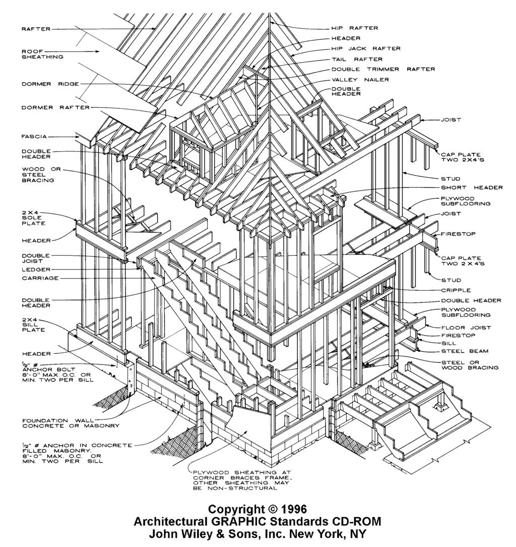
14 ROOFING AND ROOF SHEATHING 12 4 ALTERNATIVE FRIEZE BLOCK W/SCREENED VENT LOCATION FRIEZE BLOCK W/SCREENED VENT TRIM CONTINUOUS FASCIA EXPOSED RAFTER TAIL STUD WALL WITH SHEATHING AND FINISH H10 H5 LTS12 SP2 SP4 H2.5 Eave and Truss Detail Details and Specifications Copyright 2001 SDSCAD E-Book Plans SDS - CAD Specialized Design Systems Web address sdscad@pcu.net 2
15 Notes Western or Platform Framing Before any of the superstructure is erected, the first floor subflooring is put down making a platform on which the walls and partitions can be assembled and tilted into place. The process is repeated for each story of the building. This framing system is used frequently. Firestopping All concealed spaces in framing, with the exception of areas around flues and chimneys, are to be fitted with 2 in. blocking arranged to prevent drafts between spaces. Exterior Wall Framing One-story buildings: 2 x 4's 16 in. or 24 in. o.c.; 2 x 6's, 24 in. o.c. Two and three stories: 2 x 4's, 16 in o.c.; 2 x 6's, 24 in. o.c. Bracing Exterior Walls Because floor framing and wall frames do no interlock, adequate sheathing must act as bracing and provide the necessary lateral resistance. Where required for additional stiffness or bracing, 1 x 4's may be let into outer face of studs at 45 angle secured at top, bottom, and to studs. Bridging for Floor Joists May be omitted when flooring is nailed adequately to joist; however, where nominal depth-tothickness ratio of joists exceeds 6, bridging would be installed at 8 ft 0 in. intervals. Building codes may allow omission of bridging under certain conditions.
16
17 GENERAL NOTES: 2. VERIFY ALL DIMENSIONS PRIOR TO STARTING THE WORK. DO NOT SCALE DRAWINGS. WRITTEN DIMENSIONS TAKE PRECEDENCE. 3. ESTABLISH AND VERIFY ALL OPENINGS AND INSERTS FOR MECHANICAL, ELECTRICAL AND PLUMBING WITH APPROPRIATE TRADES, DRAWINGS AND SUB-CONTRACTORS PRIOR TO CONSTRUCTION. 4. CONNECT WATER, GAS, ELECTRIC LINES TO EXISTING UTILITIES IN ACCORDANCE WITH LOCAL CITY BUILDING CODES. SOIL: 1. ALLOWABLE SOIL PRESSURE P.S.F. MINIMUM MIN. FTG. DEPTH PER DETAILS. CONCRETE: 1. FOUNDATIONS DAYS. TYPE II CONC. 5 BAG. 3. PROVIDE CONSTRUCTION 400 SQ. FT. MAXIMUM. 4. WALKS AND DRIVES DAYS, NO FLY ASH. STRUCTURAL STEEL: 2. BOLTS - ASTM A-307. LATEST AISC AND AWS CODES APPLY. ALL CONST. PER LATEST AISC HANDBOOK. MIN. EMBEDMENT OF ALL BOLTS IN MASONRY, GROUT OR CONC. TO BE 7". 3. ALL EXPANSION BOLTS TO BE "WEDGIT", RAM-SET, OR RED HEAD PHILLIPS (I.C.B.O. APPROVED) TYPE WITH A 360 EXPANSIVE WEDGING ACTION. 4. SEE DETAILS FOR SIZE. WELDING: STRUCTURAL 1. COMPLY WITH ALL APPLICABLE STATE, COUNTY AND LOCAL BUILDING CODES, ORDINANCES AND REGULATIONS PERTAINING TO THIS CONSTRUCTION. 2. PROVIDE TERMITE PROTECTION OVER A.B.C. PER GOVERNMENTAL REGULATIONS. 2. FLOOR SLABS DAYS. MAX. SLUMP = 3", NO FLY ASH 1. ASTM A-36, Fy = 36 KSI, STRUCTURAL TUBES SHAL BE ASTM A-500 (Fy-46KSI) 1. E70xx LOW HYDROGEN RODS LUMBER: 1. ALL SAWN LUMBER SHALL BEAR STAMP OF WWPA OR APPROVED TESTING AGENCY. 2. ROOF JOISTS, FLOOR JOISTS, BEAMS, LEDGERS AND PLATES TO BE DOUGLAS FIR #2 OR BETTER. 3. STUDS TO BE HEMLOCK FIR, STUD GRADE OR APPROVED EQUAL. TRUSSES: 1. TO BE MANUFACTURED BY CITY AND STATE APPROVED FABRICATOR. (AS REQ'D. BY GOVERNING MUNICIPALITY). Copyright 2001 SDSCAD E-Book Plans SDS - CAD Specialized Design Systems Web address sdscad@pcu.net
18 NAILING SCHEDULE: 1. STUD TO SOLE PLATE END NAIL2-16d 2. DOUBLED STUDS FACE NAIL 24" O.C. 3. DB. TOP PLATE FACE NAIL 16" O.C. 4. TOP PLATE TO STUD END NAIL W/ 2-16d 5. HEADER TO STUD 3-16d 6. ALL OTHER NAILING SHALL BE PER U.B.C. TABLE 25-Q UNLESS OTHERWISE NOTED 7. EXTERIOR SIDING SHALL BE NAILED TO FRAMING WITH 6d 6" EDGES AND 12" O.C. AT INTERMEDIATE SUPPORTS. PLYWOOD: 1. ROOF PLYWD. SHALL BE 1/2" STD. GRADE SHEATHING (5-PLY) W/ EXTERIOR GLUE. SPAN INDEX RATIO 32/16 W/ STAMP OF APPROVED TESTING AGENCY OR ORIENTED STRAND BOARD NER ROOF PLYWOOD SHALL BE NAILED W/ 16" O.C., EDGES, BEARING & BOUNDAR & 12" O.C. INTERMEDIATE. FRAMING: 1. JOIST HANGERS AND OTHER MISCELLANEOUS FRAMING ANCHORS SHALL BE AS MANUFACTURED BY SIMPSON COMPANY OR APPROVED EQUAL. 2. ALL BEARING STUD WALLS TO BE 16" O.C. INTERIOR AND EXTERIOR AS NOTED ON PLANS. 3. ALL BEARING PARTITIONS SHALL HAVE DOUBLE TOP PLATES. 4. ROOF AND FLOOR PLYWOOD SHEATHING PANEL EDGES SHALL BEAR ON FRAMING MEMBERS AND BUTT ALONG THEIR CENTER LINES WITH PANEL EDGES STAGGERE AND FACE GRAIN PERPENDICULAR TO SUPPORT. 5. FIRE STOPS SHALL BE PLACED IN ALL CONCEALED SPACES IN WALLS, AT FURRED SPACES & AT FLOOR/CEILING LEVELS SO THAT NO CONCEALED SPACE EXCEEDS TEN FEET. REINFORCING STEEL: 1. ASTM A FY = 60 KSI. 2. STEEL REINFORCING BARS SHALL BE DEFORMED GRADE 60. LAP VERTICAL BARS A MIN. OF 36 BAR DIAMETERS. TIE W/ APPROVED WIRE TIES. Copyright 2001 SDSCAD E-Book Plans SDS - CAD Specialized Design Systems Web address sdscad@pcu.net
19 SITE WORK: 1. MAKE SURE SETBACKS ARE IN COMPLIANCE WITH THOSE SHOWN ON PLANS. 2. SEISMIC ZONE, NO ALL STUMPS ROOTS AND ORGANIC MATTER SHALL BE REMOVED FROM THE SOIL IN THE AREA OF THE BUILDING. 4. LOT MUST BE GRADED TO INSURE PROPER DRAINAGE. THIS MUST BE COMPLETED PRIOR TO FINAL INSPECTION. 5. SOIL SHOULD NOT BE A HIGHLY EXPANSIVE SOIL TYPE WITH OUT HAVING A SOIL REPORT PREFORMED BY A SOILS ENGINEER AND RECEIVING APPROVAL FROM LOCAL BUILDING DEPARTMENT TO CONSTRUCT BUILDING ON SAID TYPE SOIL. 6. SOIL BEARING CAPACITY ASSUMED TO BE 1500 PSI AT 2' BELOW ADJACENT FINISHED GRADE FOR DESIGN. 7. FINISHED FLOOR TO BE 16" MIN. ABOVE LOT'S OUTFALL. 8. THAT PORTION OF THE FOUNDATION WHICH SUPPORTS TWO STORIES SHALL HAVE AN 8" MIN. STEMWALL. 9. BOTTOM OF FOOTINGS SHALL BE PLACED 30" MIN. BELOW EXISTING GRADE AND TOPS OF STEMS SHALL BE 10" MIN. ABOVE FINISHED GRADE. CONCRETE: 1. ALL SLABS ARE TO BE 4" CONC. OVER 4" GRAVEL UNLESS OTHERWISE NOTED ON THE PLANS. 2. CONCRETE TO BE ACI , TYPE II CEMENT, 2500 P.S.I. AT 28 DAYS, 5" MAX. SLUMP. 3. REINFORCING TO BE ASTM A615-BARS WITH Fy=60 K.S.I. LAP 30 DIA. MIN. AT SPLICES OR WELD PER ACI STD. 4. CONCRETE DESIGN BASED ON Fc 2000 P.S.F., Fc 2500 P.S.I. FOR QUALITY ONLY. 5. ANCHOR BOLTS SHALL BE A-307 EMBEDDED 7" MIN. INTO CONCRETE OR MASONRY GROUT. ROOF FRAMING: 1. FASCIA TO BE 2"x 4" DOUGLAS FIR PER DETAIL SHEET. 2. FOR SOFFIT SIZE SEE DETAIL SHEET. 3. FOR SPANS AND DIMENSIONS REFER TO FLOOR PLANS. 4. TRUSSES ARE TO BE AN APPROVED TRUSS DESIGN FROM THE TRUSS MANUFACTURE'S ENGINEER. 5. USE SIMPSON H-1 HURRICANE ANCHORS AT EACH TRUSS OR RAFTER TO WALL CONNECTION. 6. SOLID BLOCKING REQUIRED BETWEEN JOISTS, RAFTERS, AND TRUSSES OVER ALL BEARING WALLS. SUCH BLOCKING SHALL BE 1 1/2" MIN. THICKNESS AND FULL DEPTH OF JOISTS, RAFTERS, OR TRUSSES. 7. MINIMUM HEADER SIZES SHALL BE ACCORDING TO THE HEADER SIZE TABLE UNLESS OTHERWISE NOTED. 8. BASIS OF DESIGN ROOF LIVE/SNOW LOAD OF 37 P.S.F., AND ROOF DEAD LOAD OF 15 P.S.F. 9. PLYWOOD ROOF DECKING TO BE 1/2" THICK, 24/0, CDX OF 7/16 WAFFER. WOODS AND PLASTICS: GENERAL FRAMING: (DOUGLAS FIR) 1. MINIMUM HEADER SIZES SHALL BE ACCORDING TO THE FOLLOWING TABLE UNLESS OTHERWISE NOTED. HEADER SIZES (SINGLE STORY CONSTRUCTION) 2'-0" TO 4'-0" SPAN 2-2x4's 4' + TO 6'-0" SPAN 2-2x6's 6' + TO 8'-0" SPAN 2-2x8's 8' + TO 10'-0" SPAN 2-2x10's 10' + TO 12'-0" SPAN 2-2x12's HEADER SIZES (TWO STORY CONSTRUCTION) 2'-0" TO 3'-0" SPAN 2-2x4's 3' + TO 5'-0" SPAN 2-2x6's 5' + TO 7'-0" SPAN 2-2x8's 7' + TO 8'-0" SPAN 2-2x10's 2. BRACE ALL EXTERIOR WALLS AND CROSS-STUD PARTITIONS AT EACH END OF BUILDING AND AT LEAST EVERY 25' OF LENGTH BUY ONE OF THE FOLLOWING: A. SIMPSON WB 126 WALL BRACING WITH 3-16d NAILS AT EACH END AND 1-8d NAILS AT EACH STUD. B. PLYWOOD SHEATHING OF A MINIMUM THICKNESS OF 3/8 INCH. 3. FIRE STOPPING: A. FIREBLOCK STUD SPACES OVER 10' IN HEIGHT, FURRED SPACES, SOFFITS, DROP CEILINGS, COVE CEILINGS, STAIR STRINGERS AT TOP AND BOTTOM OF RUN, BEARING WALLS AND CEILING JOIST LINES, ETC. FIRESTOPPING SHALL CONSIST OF 2" NOMINAL LUMBER B. FIRESTOP OPENINGS AROUND VENTS, PIPES, DUCTS, CHIMNEYS, AND FIREPLACES AT CEILING AND FLOOR LEVELS WITH APPROVED NONCOMBUSTIBLE MATERIALS. 4. CDX PLYWOOD IS NOT APPROVED WHERE EXPOSED TO WEATHER, I.E. ROOF OVERHANGS. 5. EXTERIOR WALL FRAMING TO BE 2"x 6" STUDS AT 16" O.C.. INTERIOR WALL FRAMING AT NON-BEARING WALLS TO BE 2"X 4" STUDS AT 24" O.C. AND AT BEARING WALLS 2"x 4" STUDS AT 16" O.C. WITH DOUBLE TOP PLATE. 6. SHEAR WALL TO BE 3/8" CDX PLYWOOD APPLIED HORIZONTALLY. 7. ALL STRESS GRADE LUMBER SHALL COMPLY WITH WCLA SPECS. AND BEAR APPROVAL STAMP ON ALL PIECES IN PLACE. 8. FRAMING LUMBER SHALL BE DOUGLAS FIR CONSTRUCTION GRADE Fb 1450 OR BETTER UNLESS OTHERWISE NOTED. 9. NAILING TO BE PER CURRENT U.B.C. UNLESS OTHERWISE NOTED. 10. ALL BEARING PARTITIONS SHALL HAVE DOUBLE TOP PLATES. 11. STRUCTURAL GLUED LAMINATED TIMBERS TO BE STAMPED BY AN APPROVED AGENCY. 12. USE REDWOOD OR PRESSURE TREATED SOLE PLATES AT ALL EXTERIOR WALLS. FLOOR FRAMING: 1. ALL FLOOR JOIST TO BE DOUGLAS FIR #2 OR 16" O.C. UNLESS OTHERWISE NOTED. 2. FOR SPANS AND DIMENSIONS REFER TO FLOOR PLANS. 3. USE SIMPSON H 2.5 HURRICANE ANCHORS AT EACH FLOOR JOIST TO BEARING WALL CONNECTION. 4. SOLID BLOCKING BETWEEN JOISTS OVER ALL BEARING WALLS, AND MIDSPANS SUCH BLOCKING SHALL BE 2" MIN. THICKNESS AND FULL DEPTH OF JOISTS. 5. MINIMUM HEADER SIZES SHALL BE ACCORDING TO THE HEADER SIZE TABLE UNLESS OTHERWISE NOTED. 6. BASIS OF DESIGN: FLOOR LIVE LOAD OF 40 P.S.F., AND FLOOR DEAD LOAD OF 15 P.S.F. 7. FLOOR DECKING TO BE 3/4" THICK T & G WAFER BOARD. 8. JOIST HANGERS TO BE SIMPSON U210 OR EQUAL UNLESS OTHERWISE NOTED. 9. DOUBLE JOISTS AND OR DOUBLE BLOCKING AT ALL INTERIOR WALLS. STAIRS: 1. STAIRS TO BE CONSTRUCTED WITH THE FOLLOWING MATERIALS: 2x6 KICK PLATE ANCHOR TO CONCRETE WITH EXPANSION TYPE ANCHOR BOLTS, 2x12 TREADS NOSING 1 1/8" MIN., 3-2x12 STRINGERS REQUIRED, 2x12 BLOCKING, 3/4" WAFER BOARD RISERS AND 2x6 LEDGER. 2. HANDRAIL/GUARDRAILS FINAL STYLE, MATERIAL AND COLOR TO BE OWNER'S CHOICE. DESIGN TO BE PER U.B.C GUARDRAILS TO BE 42" HIGH MIN. FROM FLOOR. 4. HANDRAILS TO BE 34"-38" ABOVE TREAD NOSING. 5. OPEN RAILING TO HAVE INTERMEDIATE RAILS OR ORNA- MENTAL PATTERN SUCH THAT A SPHERE 4" ROUND CANNOT PASS THOROUGH. 6. MINIMUM STAIR REQUIREMENTS: MAX. 8" RISE, MIN. 9" RUN, MINIMUM HEAD CLEARANCE 6'-8". 7. PREFERRED STAIR REQUIREMENTS: RISE 7" TO 7 1/2", RUN 11" TO 12", MINIMUM HEAD CLEARANCE 7'-0". THERMAL AND MOISTURE PROTECTION: 1. ASPHALT SHINGLES OVER TYPE 30 FELT OVER 7/16" MIN. WAFFER BOARD WITH FOUR NAILS EACH. 2. R-38 INSULATION IN CEILING AND R-19 INSULATION IN EXTERIOR WALLS. 3. INSTALL CAULKING COMPOUND AT ALL PENETRATIONS IN BUILDING ENVELOPE, I.E., HOLES DRILLED IN TOP PLATES AROUND WINDOWS, DOORS, SERVICE ENTRANCE PANEL. 4. ENCLOSED ATTICS AND SPACES BETWEEN RAFTERS SHALL HAVE CLEAR CROSS-VENTILATION AREAS TO THE OUTSIDE. VENTS SHALL PROVIDE AIR INTAKE TO MEET SEC (C) CURRENT U.B.C.. ATTICS SHALL BE PROVIDED WITH AN ACCESS OPENING 22"x30" WITH MIN. HEAD ROOM ABOVE ACCESS OPENING OF 30". 5. POLYSTRENE INSUL. BD. SHALL NOT BE EXPOSED TO ATTIC. REPLACE POLYSTRENE INSUL. BD. AT ATTIC WITH APPROVED BLACK INSUL. BD. OR SEPARATE POLYSTRENE INSUL. BD. FROM ATTIC WITH 1 LAYER OF 1/2" SHEETROCK (SEC. 1712(B)3, CURRENT U.B.C.). DOORS, WINDOWS, AND GLASS: 1. ALL BEDROOM WINDOWS TO BE 44" MAX. OFF OF FINISHED FLOOR. SUCH WINDOWS SHALL HAVE A CLEAR OPENING OF 5.7 SQ. FT. MIN., CLEARANCE HEIGHT OF 24" MIN., CLEARANCE WIDTH 20" MIN. PER SEC.1204 CURRENT U.B.C.. 2. ALL INTERIOR DOORS TO HAVE BASE BOARD TYPE DOOR STOPS (HINGE TYPE OPTIONAL). 3. ALL EXTERIOR DOORS TO BE SOLID CORE. 4. DOOR OPENING INTO THE GARAGE FROM THE LIVING QUARTERS TO BE SOLID CORE AND EQUIPPED WITH A SELF CLOSING DEVICE. 5. FRAMELESS GLASS DOORS, GLASS IN DOORS, FIXED GLASS PANELS AND ALL GLASS WITHIN 18" OF FLOOR OR 12" OF ANY DOOR AND SIMILAR GLAZED OPENINGS SUBJECT TO HUMAN IMPACT SHALL BE TEMPERED GLASS AND COMPLY WITH SEC CURRENT U.B.C.. FINISHES: 1. FINISHED CEILINGS TO HAVE 1/2" DRYWALL W/ SKIP TOWEL FINISH OR AS DIRECTED BY OWNER / BUILDER. 2. INTERIOR WALL TO HAVE 1/2" DRYWALL TEXTURED AS DIRECTED BY OWNER / BUILDER. 3. 5/8" DRYWALL IS REQUIRED AT STAIRWAYS WALLS, CEILING AND UNDER STAIRS. 4. 5/8" DRYWALL ON CEILING (TYPE "X") OF GARAGE AND WALLS OF GARAGE ADJACENT TO LIVING AREA. 5. USE 5/8" SHEET ROCK ON CEILING WHERE SUPPORTED AT 24" ON CENTER. 6. DRYWALL SHALL BE NAILED 4" O.C. AT EDGES & 6" O.C. IN THE FIELD OF EACH SHEET. 7. USE TYPE "WR" SHEETROCK AS BACKING AT ALL SHOWER LOCATIONS ALONG WITH CERAMIC TILE OR APPROVED EQUAL TO A HEIGHT OF 70" ABOVE FLOOR DRAIN. (SEC.5406 CURRENT U.B.C.) MASONRY: 1. PROVIDE HORIZONTAL JOINT REINFORCING AT 16" O.C. FOR ALL MASONRY WORK. 2. BRICK VENEER SHALL BE FASTENED TO WALL PER SEC , CURRENT U.B.C. 3. ALL MASONRY MATERIALS USED MUST COMPLY WITH SECTION 2403 CURRENT U.B.C. PLUMBING: 1. INSPECTION IS REQUIRED PRIOR TO BACKFILL OF WATER, GAS AND SEWER LINES. 2. INSTALL APPROVED AIR-GAP FITTINGS ON DISCHARGE SIDE OF DISHWASHER. 3. ALL EQUIPMENT TO BE NEW AND OF EQUAL QUALITY AS SPECIFIED. 4. AFTER THE PLUMBING SYSTEM INSTALLATION IS COMPLETED THE CONTRACTOR SHALL CONDUCT AN OPERATION TEST FOR APPROVAL. 5. PLUMBING SHALL BE DESIGNED FOR WATER SOFTENING EQUIPMENT EXCEPT THAT RAW WATER LINES SHALL BE PROVIDED TO OUTSIDE HOSE BIBS. 7. ALL SHOWER HEADS ARE TO BE INSTALLED AT 6'-6" ABOVE FINISHED FLOOR OF SHOWER OR TUB. 8. USE ABS FOR WASTE AND VENT PIPING AND COPPER FOR WATER PIPING. 9. PROVIDE HOT WATER RELIEF VALVE FOR WATER HEATER AND DRAIN. 10. MAIN PLUMBING STACKS SHALL RUN UNDIMINISHED IN SIZE (3" MIN.) AND DIRECT AS POSSIBLE FROM THE MAIN DRAIN TO THE OPEN AIR ABOVE THE ROOF. 11. TOILETS TO BE SET WITH A MIN. OF 15" FROM ITS CENTER TO A VERTICAL SURFACE (SEC. 907(C) U.P.C. & SEC. 511(A) CURRENT U.B.C.) CLIMATE CONTROL: 1. FOR A/C UNITS INSTALLED EITHER IN ATTIC OR ON SECOND FLOOR AN EXTRA CORROSIVE RESISTANT WATER TIGHT PAN IS REQUIRED PER U.M.C. SEC PROVIDE EXHAUST FAN AT BATHROOM AND AT THE KITCHEN WHERE SHOWN ON THE PLANS. 3. DUCTWORK SHALL COMPLY WITH CH. 10 OF CURRENT U.B.C. 4. FURNACE SYSTEM AND INSTALLATION OF FURNACE TO COMPY WITH CHAPTER 7 OF CURRENT U.B.C. 5. ALL DUCT REGISTERS TO BE OPERABLE AND ABLE TO BE SMOOTHLY CLOSED AND OPENED BY THE HOME OWNER. ELECTRICAL SYSTEMS: 1. INSPECTION IS REQUIRED PRIOR TO BACKFILL OF LINES. 2. PROVIDE 20 FT. OF NO. 4 COPPER WIRE AS GROUND ELECTRODE INFOUNDATION FOOTING. 3. BOND INTERIOR PIPING SYSTEM WITH #8 BARE COPPER. 4. PROVIDE MAIN JUMPING BOND WITH #4 BARE COPPER. 5. ELECTRICAL SERVICE IS TO BE 100 AMP SERVICE, 120/240 VOLT, 1 PHASE RAINTIGHT, UNDERGROUND. 6. PROVIDE SEPARATE 20 AMP CIRCUITS TO WASHER. 7. PROVIDE 20 AMP CIRCUITS TO FAMILY AND DINING ROOM, AND A MINIMUM OF TWO 20 AMP CIRCUITS TO KITCHEN. 8. PREWIRE FOR T.V., TELEPHONE IN KITCHEN, FAMILY ROOM, LIVING ROOM, AND IN EVERY BEDROOM. 9. INSTALL GROUND FAULT CURRENT INTERRUPTER ON EX- TERIOR, GARAGE, KITCHEN AND BATHROOM OUTLETS. 10. BOTTOM HALF OF OUTLET CONTROLLED BY SWITCH WHEN SHOWN. 11. ALL OUTLETS IN KITCHEN ARE TO BE AT +44" EXCLUDING THOSE FOR THE REF'G., RANGE, DISP., DISHWASHER. 12. MAXIMUM SPACING OF OUTLETS SHALL NOT EXCEED 12 FT. ALONG WALL LINE AND AT ANY WALL OVER 24" WIDE IN ALL ROOMS EXCEPT KITCHEN, BATH, UTILITY, GARAGE. 13. INSTALL LIGHT IN WALK-IN CLOSET 18" MIN. HORIZ. FROM ANY SHELF. 14. PROVIDE A VENTILATION FAN CAPABLE OF PRODUCING A CHANGE OF AIR EVERY 12 MINUTES FOR BATH OR UTILITY ROOMS WITHOUT THE REQUIRED WINDOW VENTILATION. 15. PROVIDE SMOKE DETECTOR ALARM CONFORMING TO SEC. 1210(A) U.B.C. AND LOCAL BUILDING CODES IN EVERY BEDROOM AND ON EACH FLOOR.
20 ID Su Flr Size Item Count Un 1 General 2 GN /4 high walfoundation 8" Concrete Stem 126 ft 3 GN /8 high walsiding ft 4 GN /8 high walinterior-4 55 ft 5 GN /16 high walsiding-8 76 ft 6 GN /8 high walsiding-8 52 ft 7 GN /16 high wainterior-4 26 ft 8 GN /8 high walinterior-4 38 ft 9 GN /8 high wainterior-4 18 ft 10 GN /16 high winterior-4 4 ft 11 GN /16 high wainterior-4 4 ft 12 GN11 2 heated ceiling area 988 sqft 13 GN12 2 heated wall area 351 sqft 14 GN13 2 heated glass area 27 sqft 15 GN /8 high walsiding-8 36 ft 16 Subtotal: 17 Foundation 18 FO1 0 8" thick Concrete Concrete 6.24 cuyd 19 FO2 0 2x6" treated mud sill 126 ft 20 FO3 0 1/2x6" foam sill seal 126 ft 21 FO4 0 foundation bolts FO5 0 16x8"h concrete footing 4.12 cuyd 23 FO6 0 no. 4 rebar (footing) 267 ft 24 FO7 0 no. 4 horiz. rebar (wall) 800 ft 25 FO8 0 no. 4 vert. rebar (wall) 259 ft 26 FO sq ft concrete slab cuyd 27 FO sq ft steel mesh for slab 988 sqft 28 Subtotal: 29 Subfloor 30 SF1 2 4x8'x3/4" sheetfloor sheathing SF2 2 2x12"-16'+ rim joists - lumber 128 ft 32 SF3 2 2x12"-26' floor joists - lumber SF4 2 2x12"-16'+ floor joists - lumber 20 ft 34 SF5 2 2x12"-10' floor joists - lumber 2 35 SF6 2 2x6"-18' ceiling joists - lumber Subtotal: 37 Framing 38 F1 1 2x6-16ft+ fir plate 393 ft 39 F2 1 2x6"-92 5/8" fir stud F3 1 2x6-16ft+ fir stud stock 112 ft 41 F4 1 2x4"-92 5/8" fir stud F5 1 2x7-16ft+ header - lumber 67 ft 43 F6 1 2x6"-9 7/8" fir stud 4 44 F7 1 2x6"-1 5/8" fir stud F8 1 2x12-16ft+ header - lumber 34 ft 46 F9 1 2x4-16ft+ fir plate 164 ft 47 F10 1 2x4"-5 7/8" fir stud 9 48 F11 1 2x4-16ft+ fir stud stock 47 ft 49 F12 1 2x4"-7 5/8" fir stud 2 50 F13 1 2x6-16ft+ header - lumber 6 ft 51 F14 2 2x6-16ft+ fir plate 417 ft 52 F15 2 2x6-16ft+ fir stud stock 119 ft 53 F16 2 2x6"-92 5/8" fir stud F17 2 2x7-16ft+ header - lumber 14 ft 55 F18 2 2x4"-92 5/8" fir stud F19 2 2x4-16ft+ fir plate 282 ft 57 F20 2 2x4"-77 1/8" fir stud 23
21 ID Su Flr Size Item Count Un 58 F21 2 2x4-92 5/8" Fir Stud 16" OC F22 2 2x4-16ft+ fir stud stock 61 ft 60 F23 2 2x4"-7 5/8" fir stud 2 61 F24 2 2x6-16ft+ header - lumber 6 ft 62 F25 2 2x4"-1 7/8" fir stud 5 63 F26 2 2x11-16ft+ header - lumber 13 ft 64 F27 3 2x6-16ft+ fir plate 78 ft 65 F28 3 2x6-16ft+ fir stud stock 61 ft 66 Subtotal: 67 Siding 68 S /2" wide Siding Wood Pine 970 ft 69 S2 1 4x8x1/2 Sheet Sheetrock S3 1 house wrap 1063 sqft 71 S /2" wide Siding Wood Pine 449 ft 72 S5 2 4x8x1/2 Sheet Sheetrock S6 2 house wrap 420 sqft 74 S /2" wide Siding Wood Pine 91 ft 75 Subtotal: 76 Ext Trim 77 EX1 1 1x4-16ft+ exterior sill - color 9, white 18 ft 78 EX2 1 1x4-16ft+ ext. window casing - color 9, w 63 ft 79 EX3 1 1x7-36" 2 80 EX4 1 1x4-16ft+ ext. door casing - color 9, whit 18 ft 81 EX5 1 7 in ext. door jamb - color 9, white 18 ft 82 EX6 1 1x4-16ft+ garage door casing - color 9, w 47 ft 83 EX7 1 7 in garage door jamb - color 9, wh 47 ft 84 EX8 1 1x4-16ft+ ext. door casing 53 ft 85 EX9 1 7 in ext. door jamb 18 ft 86 EX10 1 1x5-36" 2 87 EX in ext. door jamb 35 ft 88 EX " wide Fir Stock Std. + Btr. 21 ft 89 EX13 2 1x4-16ft+ exterior sill - color 9, white 8 ft 90 EX14 2 1x4-16ft+ ext. window casing - color 9, w 27 ft 91 Subtotal: 92 Roofing 93 R1 1 ridge cap 123 ft 94 R2 1 Roofing Dimensional Comp sqft 95 R3 1 4x8' sheets roof sheathing R4 1 2x6" 16" OC rafters - fir 1479 ft 97 R5 1 2x8" gable fascia 86 ft 98 R6 1 2x8" eave fascia 82 ft 99 R7 1 metal drip edge 168 ft 100 R8 1 gutter 82 ft 101 R9 1 downspout R10 2 2x8"-16'+ ridge board - lumber 123 ft 103 R11 2 2x6"-12' rafters - lumber R12 2 2x8"-41' rafters - lumber R13 2 2x8"-13' rafters - lumber R14 2 4x2"-16'+ rafters - lumber 80 ft 107 R15 2 2x6"-10' rafters - lumber R16 2 2x6"-11' rafters - lumber R17 2 2x8"-11' rafters - lumber Subtotal: 111 Insulation 112 IN1 2 12x16x48" battsceiling insulation IN2 2 6x16x93" batts wall insulation Subtotal:
22 ID Su Flr Size Item Count Un 115 Flooring 116 FL1 2 Carpet b4 852 sqft 117 FL2 2 4x8' sheets underlayment Subtotal: 119 Wall Brd 120 WB1 0 4x8'-1/2" ceiling wall board WB2 1 4x8x1/2 Sheet Sheetrock WB3 1 4x8'-1/2" ceiling wall board WB4 1 4x8x1/2 (wp) - sheet sheetrock WB5 2 4x8x1/2 Sheet Sheetrock WB6 2 4x8'-1/2" ceiling wall board WB7 3 4x8x1/2 Sheet Sheetrock Subtotal: 128 Windows 129 W1 1 36x36 double hung - color 9, white W2 1 36x54 double hung - color 9, white W3 2 36x54 double hung - color 9, white Subtotal: 133 Doors 134 D1 1 36x80x1 3/4R ext. - color 9, white D2 1 96x84 garage - color 9, white D3 1 36x80x1 3/4L ext D4 1 36x80x1 3/4R ext D5 1 32x80x1 3/8R D6 2 32x80x1 3/8L D7 2 36x80 bifold Subtotal: 142 Cabinets 143 C1 1 BD3636 gar. base cab C2 1 34x6" utility cab. drawer C /16x21 1/2RP-3-REC door (utility) C4 1 countertop - marble travertine 16 sqft 147 C5 1 front cap (utility) 13 ft 148 C6 1 backsplash (utility) 8 ft 149 C7 1 BDR2436 gar. base cab C8 1 22x6" utility cab. drawer C9 1 22x21 1/2" RP-3-REC door (utility) C10 1 W3030 gar. wall cab C /16x28" RP-3-1CCATH door (utility) C12 1 BS3636 gar. base cab C13 1 WR2430 gar. wall cab C x28" RP-3-1CCATH door (utility) Subtotal: 158 Int Trim 159 T1 1 1x2-16ft+ window apron - color 9, white 17 ft 160 T2 1 1x2-16ft+ sill - color 9, white 17 ft 161 T3 1 1x2-16ft+ interior casing - color 9, white 78 ft 162 T4 1 1x2-16ft+ interior casing 85 ft 163 T5 1 5 in interior jamb 17 ft 164 T6 1 36x11 3/8-1" stair tread T7 1 36x7 1/4" riser T treads stair stringer T9 2 1x2-16ft+ window apron - color 9, white 7 ft 168 T10 2 1x2-16ft+ sill - color 9, white 7 ft 169 T11 2 1x2-16ft+ interior casing - color 9, white 26 ft 170 T /2" wide int. railing 158 in 171 T /2" wide middle rail 158 in
23 ID Su Flr Size Item Count Un 172 T /4" diam. baluster T /2" square newel post T /2" square half newel post T17 2 1x2-16ft+ interior casing 74 ft 176 T in interior jamb 37 ft 177 T19 2 1x6-16ft+ base molding 281 ft 178 Subtotal: 179 Fixtures 180 FX1 1 36W36D Corner (right) - color 10, shiny FX2 1 30W19D Free Standing (rect) - color FX3 1 31W34D Standard - color 10, shiny whit FX4 1 32W21D Double 32" - marble travertine Subtotal: 185 Appliance 186 A1 1 36W31D Side-by-Side - color 10, shiny w A2 1 28W27D Dryer (gas) - color 10, shiny w A3 1 26W27D Washer - color 10, shiny white A4 1 30W26D Elec (medium) - color 10, shiny A5 1 36W7D Convection Heater - color 10, s Subtotal: 192 Electrical 193 E1 1 wall mount Duplex (low res) E2 1 wall mount 220V (low res) E3 1 wall mount Single Pole E4 1 wall mount Porch Lantern E5 1 wall mount Three Way E6 1 wall mount Weatherproof E7 1 wall mount Electrical Panel E8 1 wall mount GFCI E9 1 wall mount Half Cone E10 1 ceiling mount Smoke Detector E11 1 ceiling mount Half Dome E12 2 wall mount Duplex (low res) E13 2 wall mount Single Pole E14 2 ceiling mount Smoke Detector E15 2 ceiling mount Half Dome Subtotal: 209 Hardware 210 H1 1 utility cab drawer handle H2 1 utility cab door handle H3 1 utility cab drawer glide H4 1 utility cab door hinge Subtotal: Total:
14' x 24' Garage Plan
 14' x 24' Garage Plan SDS-CAD Specialized Design Systems www.sdscad.com email sdscad@pcu.net Copyright 2002 14'-0" (vert)-g 24'-0" 12 in 12 GARAGE 13'-4" x 23'-4" 12 in 12 3068 19'-0" 3'-0" 2'-0" 24'-0"
E-Blueprints. Shed WorkShop Loft 20' x 20' 800 sq. feet Shed Roof 2 x Framed Walls 8' Doors 8' ceiling Height E-BLUEPRINTS C ABINS G ARAGES
 SDS-CAD - Specialized Design Systems E-BLUEPRINTS C ABINS G ARAGES Shed WorkShop Loft 20' x 20' 800 sq. feet Shed Roof 2 x Framed Walls 8' Doors 8' ceiling Height E-Blueprints UP 2x12 joists 16" OC SDS-
Custom 22' x 40' - 16' Tall Garage Plan #g227 By SDS-CAD Specialized Design Systems
 P O Box 34 Mendon, Utah Custom 22' x 40' - 16' Tall Garage Plan #g22 By Page 1 Title Page Page 2 Main Floor Plan Page 3 Foundation Plan Page 4 Elevation Views Page 5 Framing and Details Page 6 Typical
Custom 30 x 48-14' Tall Garage Plan #g226 By SDS-CAD Specialized Design Systems
 P O Box 34 Mendon, Utah Custom 30 x 48-14' Tall Garage Plan #g226 By Page 1 Title Page Page 2 Main Floor Plan Page 3 Foundation Plan Page 4 Elevation Views Page 5 Framing and Details Page 6 Typical Section
E-Blueprints. 2 Car Garage 26' x 30' 780 sq. feet Trussed Roof 2 x 4 Framed Walls 7' Door 8' Ceiling Height E-BLUEPRINTS C ABINS G ARAGES
 SDS-CAD - Specialized Design Systems E-BLUEPRINTS C ABINS G ARAGES 2 Car Garage 26' x 30' 780 sq. feet Trussed Roof 2 x 4 Framed Walls 7' Door 8' Ceiling Height E-Blueprints SDS- CAD SDS-CAD - Specialized
GARAGE MAIN FLOOR PLAN
 #G389 14' X 24' X 8', Custom detached garage By Page 1 Page 2 Page 3 Page 4 Page BUILDING CONTRACTOR/HOME OWNER TO REVIEW AND VERIFY ALL DIMENSIONS, SPECS, AND CONNECTIONS BEFORE CONSTRUCTION BEGINS. GARAGE
Custom 24 x 26 Garage Plan Roy Hartmann Plan #g218 By SDS-CAD Specialized Design Systems CLIENT
 P O Box 34 Mendon, Utah Custom 24 x 26 Garage Plan Plan #g218 By Page 1 Title Page Page 2 Main Floor Plan Page 3 Foundation Plan Page 4 Elevation Views Page 5 Framing and Details Page 6 Typical Section
MAIN FLOOR PLAN. #G x 14 x 8 Shed - Chicken Coop By SDS-CAD Specialized Design Systems 10'-0" 3'-0" 1'-0" 14'-0" 14'-0" 1'-0" 6'-0" 3'-0"
 10'-0" BUILDING CONTRACTOR/HOME OWNER TO REVIEW AND VERIFY ALL DIMENSIONS, SPECS, AND CONNECTIONS BEFORE CONSTRUCTION BEGINS. BARN TO BE BUILT AS PER LOCAL CODE REQUIREMENTS 14'-0" BWP BWP BWP ABWP 101
GARAGE MAIN FLOOR PLAN
 12'-0" 4'-6" 3'-0" 4'-6" 3040 14'-0" LADDER LT LINE BUNK CABIN 11'-4" x 13'-4" 14'-0" BUILDING CONTRACTOR/HOME OWNER TO REVIEW AND VERIFY ALL DIMENSIONS, SPECS, AND CONNECTIONS BEFORE CONSTRUCTION BEGINS.
GARAGE MAIN FLOOR PLAN
 BUILDING CONTRACTOR/HOME OWNER TO REVIEW AND VERIFY ALL DIMENSIONS, SPECS, AND CONNECTIONS BEFORE CONSTRUCTION BEGINS. SHED TO BE BUILT AS PER IRC, UBC OR CURRENT LOCAL CODE To the best of my knowledge
GARAGE MAIN FLOOR PLAN 1
 30 year dimensional shingles and structural panel siding running vertical with 8" on center groove and horizontal siding in eaves. Nailing schedule is " on ends 12" on centers d nails. Trusses are engineered
GARAGE MAIN FLOOR PLAN 1
 30 year dimensional shingles and structural panel siding running vertical with 8" on center groove and horizontal siding in eaves. Nailing schedule is " on ends 12" on centers d nails. Trusses are engineered
GARAGE MAIN FLOOR PLAN SDSCAD Specialized Design Systems
 BUILDING CONTRACTOR/HOME OWNER TO REVIEW AND VERIFY ALL DIMENSIONS, SPECS, AND CONNECTIONS BEFORE CONSTRUCTION BEGINS. BARN TO BE BUILT AS PER IRC,UBC OR CURRENT LOCAL CODE To the best of my knowledge
36 x 48 Barn. SDS-CAD Specialized Design Systems Copright Website 48'-0" 6'-0" 14'-9 13/16" 14'-9 13/16"
 48'-0" 12'-0" 24'-0" 12'-0" (vert)-g (vert)-g UP 36'-0" 14'-9 13/16" 2 in 12 14'-9 13/16" 12'-0" 36'-0" 6'-0" 3'-0" 18'-0" 3'-0" 6'-0" 3046 3046 (vert)-v (vert)-v 3046 3068 3046 6'-0" 3'-0" 7'-6" 3'-0"
Sample Plan Not for Construction for pricing
 26' x 48' Screen Porch Garage Plans Trussed Roof, 2x Construction, 8' Walls Asphalt Shingles, Garage Space Office Space, Screened Porch 48'-0" 4" 5" 12'-0" 5" 4" 4'-0" 12'-0" 4'-0" 4'-0" 10'-0" 24'-0"
2x4 Construction 10' Ceilings 36" Brick. 28' x 30' Garage Plan. 28' x 30' Garage
 2x4 Construction 10' Ceilings 36" Brick Plan 28'-0" 30'-0" 5'-0" 12'-6" 12'-6" 9030 3068 8080 3068 9030 12'-6" 12'-0" 3'-6" 2'-0" 28'-0" 30'-0" 8080 7'-0" 7'-0" 7'-0" 7'-0" 14'-0" 14'-0" Floor Plan Scale
Gambrel Roof Garage 24' x 36' SDS-CAD Specialized Design Systems Copyright 2002
 S S S UP S 24'-0" 4'-6" 3'-0" 3'-0" 3'-0" 3'-0" 3'-0" 4'-6" 3046 3046 3046 36'-0" 12'-0" 24'-0" 10'-6" 3'-0" 10'-6" 4'-6" 3'-0" 4'-6" 3046 3046 S S 3068 2x12 joists 16" OC Micro Lam Beam 5 1/2" x 14" Min
SDS-CAD Specialized Design Systems Copyright 2002 Website: 26' x 36' Garage With Loft
 26' x 36' Garage With Loft SDS-CAD Specialized Design Systems Copyright 2002 Website: www.sdscad.com Email: sdscad@pcu.net 26'-0" 4" Concrete Slab w/ww mesh over 4" Gravel Fill See details for 8" x 36"
GARAGE MAIN FLOOR PLAN
 BUILDING CONTRACTOR/HOME OWNER TO REVIEW AND VERIFY ALL DIMENSIONS, SPECS, AND CONNECTIONS BEFORE CONSTRUCTION BEGINS. SHED TO BE BUILT AS PER IRC, UBC OR CURRENT LOCAL CODE To the best of my knowledge
GARAGE MAIN FLOOR PLAN
 30 year dimensional shingles and Metal Verticle siding over structural sheathing. Nailing schedule is " on ends 12" on centers d nails. Trusses are engineered on 24" and framing is 2" x " on 1" centers.
GARAGE MAIN FLOOR PLAN
 30 year dimensional shingles and Metal Verticle siding over structural sheathing. Nailing schedule is " on ends 12" on centers d nails. Trusses are engineered on 24" and framing is 2" x " on 1" centers.
#G445 Plans, 48'x28' x 10' detached garage with bonus room By SDS-CAD Specialized Design Systems
 Architectural asphalt shingles and horizontal True Wood 7" Reveal siding over structural panel. Nailing schedule is 6" on ends 12" on centers 6d nails. Trusses are engineered on Bonus attic trusses 24"
BARN MAIN FLOOR PLAN. #G457a 12 x 20 x 8 Gentleman Bunkhouse Shed By SDS-CAD Specialized Design Systems 12'-0" 3'-0" 4'-0" 1'-6" 3'-0" 1'-6" 20'-0"
 3'-0" 12'-0" '-0" 3'-0" BWP 010 BWP BUILDING CONTRACTOR/HOME OWNER TO REVIEW AND VERIFY ALL DIMENSIONS, SPECS, AND CONNECTIONS BEFORE CONSTRUCTION BEGINS. BARN TO BE BUILT AS PER LOCAL CODE REQUIREMENTS
Cabin Plan 24' x 32' DECK. BEDROOM 9'-8" x 14'-0" LIVING 23'-0" x 16'-7" DECK. Main Floor Plan Scale 3/16"=1'
 4'-0" 6'-3" 2'-4" 7'-5" 2'-6" 3'-9" 4'-11" 2'-6" 6'-0" 3050 DECK 15'-5" x 5'-7" WP 2868 32'-0" 14'-10" 17'-2" 6'-0" 6'-0" 5'-2" 4'-10" 6'-0" 4'-0" 3050 3050 3050 3050 2868 BEDROOM 9'-8" x 14'-0" UP SD
BWP BWP 8'-0" 5'-0" BWP 12'-0" 5'-0" 60'-0" GARAGE 19'-7" x 59'-0" GARAGE 14'-3" x 59'-0" BWP. 9' Ceiling Height 12'-0" 5'-0" BWP
 0 year dimensional shingles and Metal Verticle siding over structural sheathing. Nailing schedule is 6" on ends 12" on centers 6d nails. Trusses are engineered on 24" and framing is 2" x 6" on 16" centers.
Custom Home Design Plan #211 By SDS-CAD Specialized Design Systems
 Plans for as low as $9.99 BUILDING CONTRACTOR/HOME OWNER TO REVIEW AND VERIFY ALL DIMENSIONS, SPECS, AND CONNECTIONS BEFORE CONSTRUCTION BEGINS. BUILD AS PER UBC, IRC OR CURRENT LOCAL CODE REQUIREMENTS
Custom Home Design Plan #204 Summit By SDS-CAD Specialized Design Systems
 BUILDING CONTRACTOR/HOME OWNER TO REVIEW AND VERIFY ALL DIMENSIONS, SPECS, AND CONNECTIONS BEFORE CONSTRUCTION BEGINS. BUILD AS PER IRC, UBC OR CURRENT LOCAL CODE REQUIREMENTS Custom Home Design Plan #204
28' x 28' Cabin. Cabin Plan 28' x 28'
 28' x 28' Cabin Cabin Plan 28' x 28' SDS-CAD Specialized Design Systems email sdscad@pcu.net www.sdscad.net Copyright 2002 28'-0" 10'-0" 8'-0" 10'-0" 5'-0" 5'-0" 4'-4" 3'-8" 5'-0" 5'-0" 3040 2030 3040
Custom Cabin Design Plan #221 24' x 32' Custom Cabin Chris Lavier By SDS-CAD Specialized Design Systems
 BUILDING CONTRACTOR/HOME OWNER TO REVIEW AND VERIFY ALL DIMENSIONS, SPECS, AND CONNECTIONS BEFORE CONSTRUCTION BEGINS. "BUILD AS PER NATIONAL BUILDING CODE CANADA, THE UNIFORM BUILDING ACCESSIBILITY STANDARDS
Custom Home Design Plan #217 Cottage By SDS-CAD Specialized Design Systems
 BUILDING CONTRACTOR/HOME OWNER TO REVIEW AND VERIFY ALL DIMENSIONS, SPECS, AND CONNECTIONS BEFORE CONSTRUCTION BEGINS. HOME TO BE BUILT AS PER IRC, UBC OR CURRENT CODE Custom Home Design Plan #217 Cottage
Custom Cabin Design Plan #178 By SDS-CAD Specialized Design Systems
 Sign up for Free Newsletter - Sign up for free newsletter and receive free plans BUILDING CONTRACTOR/HOME OWNER TO REVIEW AND VERIFY ALL DIMENSIONS, SPECS, AND CONNECTIONS BEFORE CONSTRUCTION BEGINS. ELECTRICAL
Custom Home Design Plan #217 Cottage By SDS-CAD Specialized Design Systems
 BUILDING CONTRACTOR/HOME OWNER TO REVIEW AND VERIFY ALL DIMENSIONS, SPECS, AND CONNECTIONS BEFORE CONSTRUCTION BEGINS. HOME TO BE BUILT AS PER IRC, UBC OR CURRENT CODE Custom Home Design Plan #217 Cottage
Elevations. Front Elevation. Left Elevation. Back Elevation. Right Elevation CEDAR RIDGE H O M E S. Total Sq Ft = 1,647.
 4 12 Pitch Cement board siding 7" Lap 4" Corner boards Vertical Cedar T&G Siding 4" Window and Door Trim (Street facing facade) P.T. 6x6 : Wrapped & collared with cement board Trim. Stone Veneer on Garage
Left Elevation. Front Elevation. Back Elevation. Right Elevation CEDAR RIDGE H O M E S. Total Sq Ft = 1,842. Scale : 1/4" = 1'
 Plan Name 4 4" Window and door trim. (Street facing facades) 4" Corner Boards 4" Vertical Cedar Siding Left Elevation Lap siding over approved building wrap over 1 2" OSB sheathing. Front Elevation Stone
Elevations. Front Elevation. Left Elevation. Back Elevation. Right Elevation CEDAR RIDGE H O M E S. Total Sq Ft = 1,647.
 10" Belly Band Cement board shake siding Cement board siding 7" Lap Decorative Corbels Cement board siding 7" Lap 4" Corner boards Stone Veneer on Garage wings 48" high 4" Window and Door Trim (Street
GARAGE MAIN FLOOR PLAN
 REVIION 30 year dimensional shingles and Metal Verticle siding over structural sheathing. Nailing schedule is " on ends 12" on centers d nails. Trusses are engineered on 2" and framing is 2" x " on 1"
30 X 40 POLE BARN 12 HIGH SIDE WALLS 2-12 WIDE X 10 HIGH SECTIONAL GARAGE DOORS OPTIONAL WINDOWS DETAILS INCLUDED
 30 X 40 POLE BARN 12 HIGH SIDE WALLS 2-12 WIDE X 10 HIGH SECTIONAL GARAGE DOORS OPTIONAL WINDOWS DETAILS INCLUDED 3 ENTRY DOOR METAL ROOF METAL SIDING GABLE ROOF, 4/12 PITCH INDEX PAGE DESCRIPTION 1 FRONT
APPLICATION FOR FINISHED BASEMENT PERMIT
 APPLICATION FOR FINISHED BASEMENT PERMIT REAL ESTATE TAX I.D. #: - - _ - _ 7607 W College Drive Ph: (708) 361-1804 Fax: (708) 923-7112 building@palosheights.org APPLICANTS: COMPLETE ALL ITEMS AND SUBMIT
Carroll County Bureau of Permits and Inspection Residential Code Compliance Guidelines Detached Garage
 Carroll County Bureau of Permits and Inspection Residential Code Compliance Guidelines Detached Garage The following list of code requirements is intended to assist you in complying with the Code of Public
Section numbers refer to the 2018 International Residential Code (IRC), as modified, unless otherwise noted. Revised Effective Sept.
, as modified, unless otherwise noted. Revised Effective Sept.") Residential Plan Check Addendum Page 2 of 5 Building Permit # Section numbers refer to the 2018 International Residential Code (IRC), as modified, unless otherwise noted. Revised Effective Sept. 5 th,
Residential Plan Check Addendum Page 2 of 5 Building Permit # Section numbers refer to the 2018 International Residential Code (IRC), as modified, unless otherwise noted. Revised Effective Sept. 5 th,
Project Name: the candlelight. Project No. Scale: sewer line. water line 1 8"=1'-0"
 sewer line water line Site Plan scale: 1/8" = 1' 1709 POWERS BLVD. RYAN GLENN SUBDIVISON PHASE 1, BLOCK 5, LOT 3 10,84 SQ. FT. slope grade away from foundation min " in 10' or 5% if 10' is unavailable
2003 International Residential Building Code
 2003 International Residential Building Code Section R305 Ceiling Height Habitable rooms, hallways, corridors, bathrooms, toilet rooms, laundry rooms and basements shall have a ceiling height of not less
ACCESSORY STRUCTURE Building permit information For 1 & 2-family dwellings
 ACCESSORY STRUCTURE Building permit information For 1 & 2-family dwellings Building Safety Department 400-2 nd Street South St. Cloud, MN 56301 (320) 255-7239 A building permit is required for any accessory
BASEMENT FINISH PERMIT AND BUILDING CODE REQUIREMENTS (REVISED 3/6/2018)
") BASEMENT FINISH PERMIT AND BUILDING CODE REQUIREMENTS (REVISED 3/6/2018) PERMIT SUBMITTAL CHECKLIST: Signed and completed Building Permit application form. A separate Electrical permit is required from
BASEMENT FINISH PERMIT AND BUILDING CODE REQUIREMENTS (REVISED 3/6/2018) PERMIT SUBMITTAL CHECKLIST: Signed and completed Building Permit application form. A separate Electrical permit is required from
SECTION WOOD FRAMING. A. Includes But Not Limited To 1. Furnish and install wood framing and blocking as described in Contract Documents.
 SECTION 06110 WOOD FRAMING PART 1 GENERAL 1.1 SUMMARY A. Includes But Not Limited To 1. Furnish and install wood framing and blocking as described in Contract Documents. B. Products Installed But Not Supplied
front elevation right elevation
 Ridge Approx. 21'-7" :12 continuous ridge vents 30 year asphalt shingles 8" Lap Hardie Plank Siding 3 1 2" MiraTech window & door trim 3 1 2" MiraTech corner trim 40" Tall Foundation Wall front elevation
Table of Contents. Page Title
 Page Title Table of Contents 1 Floor plan/ Room utilization 2 Elevation (EAST) 3 Elevation (SOUTH) 4 Elevation (WEST) 5 Elevation (NORTH) 6 Foundation plan details 7 Foundation cross sections A Main grade
THE FLORIDA BUILDING CODE
 THE FLORIDA BUILDING CODE 1. According to the Florida Building Code, spiral stairway treads must all be identical and rise must be sufficient enough to provide a headroom of minimum. A. 6'- 4" B. 6'- 6"
CRM Homes BUILDER Mangan Drafting Jim Mangan
 BACK ELEVATION 1/8" = 1' LEFT SIDE 1/8" = 1' RIGHT SIDE 1/8" = 1' ROOF LINE NTS FRONT VIEW 1/4" = 1' A-1 Springfield MO 65610 Fremont Hills Lot 57 12/12 12/12 14/12 14/12 12/12 12/12 12/12 MAIN ROOF PITCH
Lonsdale Building Inspections Department 415 Central Street W. PO Box 357 Lonsdale, MN (507) fax (507)
 fax (507)") Lonsdale Building Inspections Department 415 Central Street W. PO Box 357 Lonsdale, MN 55046 (507) 744-2327 fax (507) 744-5554 2006 RESIDENTIAL CONSTRUCTION CHECKLIST The following checklist has been designed
Lonsdale Building Inspections Department 415 Central Street W. PO Box 357 Lonsdale, MN 55046 (507) 744-2327 fax (507) 744-5554 2006 RESIDENTIAL CONSTRUCTION CHECKLIST The following checklist has been designed
Pulaski County, Virginia
 Pulaski County, Virginia Typical Carport Enclosure Details Based on the 2009 International Residential Code CONTENTS General Requirements... 2 Emergency Escape and Rescue... 2 Foundation and Floor... 3
Anchor bolts ASTM F1554, Gr. 36 Wide flange beams ASTM A992, Fy = 50 ksi Misc. structural steel ASTM A36, Fy = 36 ksi
 STRUCTURAL NOTES MATERIAL STRENGTHS Structural Steel Reinforcing Steel Concrete Masonry Structural Lumber Anchor bolts ASTM F1554, Gr. 36 Wide flange beams ASTM A992, Fy = 50 ksi Misc. structural steel
BROCHURE # 108 CONSTRUCTION PLAN COMPONENTS
 BROCHURE # 108 CONSTRUCTION PLAN COMPONENTS Please note: This construction plan component list is to be used as a guide to assist you with your project. There may be elements unique to your project not
ADDITIONS BUILDING AND ZONING REQUIREMENTS (REVISED 4/22/2008)
") ADDITIONS BUILDING AND ZONING REQUIREMENTS (REVISED 4/22/2008) PERMIT SUBMITTAL CHECKLIST: Signed completed Building Permit application form. Two (2) Copies of a Certificate of Survey. Draw to scale the
ADDITIONS BUILDING AND ZONING REQUIREMENTS (REVISED 4/22/2008) PERMIT SUBMITTAL CHECKLIST: Signed completed Building Permit application form. Two (2) Copies of a Certificate of Survey. Draw to scale the
GENERAL BUILDING CODE AND ZONING REQUIREMENTS: Post and spread footings shall be designed and constructed below the minimum frost depth of 42 inches
 GENERAL BUILDING CODE AND ZONING REQUIREMENTS: Post and spread footings shall be designed and constructed below the minimum frost depth of 42 inches and shall be sized to carry the applicable roof and
Custom House Plans. Developed By SDS-CAD Specialized Design Systems Website:
 Custom House Plans Developed By S-CAD Specialized Design Systems Website: www.sdscad.com Email: sdscad@pcu.net Custom House Plans Cape Cod Country Estate Copyright 2003 sdscad 12'-6" 8'-3" 7'-0" 8'-6"
SUBJECT: NEW 2000 INTERNATIONAL RESIDENTIAL CODE (IRC) DATE:
 DATE:") IRC CODE UPDATES TO: RESIDENTIAL BUILDING CONTRACTORS FROM: GARY STABER, BUILDING OFFICIAL SUBJECT: NEW 2000 INTERNATIONAL RESIDENTIAL CODE (IRC) DATE: 6/1/2003 INTERNATIONAL RESIDENTIAL CODE (IRC) APPLICABILITY:
IRC CODE UPDATES TO: RESIDENTIAL BUILDING CONTRACTORS FROM: GARY STABER, BUILDING OFFICIAL SUBJECT: NEW 2000 INTERNATIONAL RESIDENTIAL CODE (IRC) DATE: 6/1/2003 INTERNATIONAL RESIDENTIAL CODE (IRC) APPLICABILITY:
CODE COMPLIANCE GUIDELINE GENERAL BUILDING
 CODE COMPLIANCE GUIDELINE This guideline has been prepared by The Calhoun County Building Department to assist Homebuilders, General Contractors, and Owner/Builders during the construction process. The
Residential Building Inspections
 Residential Building Inspections Foundations, Grade Beams, Pile Caps, Foundation Pads 1. All trenches or excavations and formwork shall be in accordance with the size(s) and configuration(s) as per approved
Building Division Informational Handout
 CITY OF SAN JOSÉ, CALIFORNIA Building Division Informational Handout Conventional Light Frame Construction Design Provisions 2007 CBC Handout No. 2-21 Published: 1/1/08 Page 1 of 3 This document summarizes
Typical Finished Basement Details
 Albemarle County, Virginia Typical Finished Basement Details Based on the 2012 Virginia Residential Code Finished basements must be constructed in conformance with these details. For requirements, details
THE ASHTON PERSPECTIVE VIEW
 THE ASHTON PERSPECTIVE VIEW TYPICAL DETAILS GENERAL DESIGN NOTES: 1. THESE DRAWINGS ARE OF A GENERAL NATURE AND ARE NOT INTENDED TO CONVEY THE METHOD OR MEANS OF CONSTRUCTION. IT IS ASSUMED THAT ALL WORK
STANDARD CONSTRUCTION PACKAGE Addendum A REV SITE & EXCAVATION Layout of the foundation and septic system as approved by local and state author
 STANDARD CONSTRUCTION PACKAGE Addendum A REV 7-3-18 SITE & EXCAVATION Layout of the foundation and septic system as approved by local and state authorities Excavate material to pour footings and foundation
Quality Inspection 8618 London Heights San Antonio, TX Phone: (210)
") Quality Inspection 8618 London Heights San Antonio, TX 78254 Phone: (210) 240-0476 PRE DRYWALL INSPECTION REPORT Prepared For: DELETED (Name of Client) Concerning: DELETED, San Antonio, TX 78258 (Address
Quality Inspection 8618 London Heights San Antonio, TX 78254 Phone: (210) 240-0476 PRE DRYWALL INSPECTION REPORT Prepared For: DELETED (Name of Client) Concerning: DELETED, San Antonio, TX 78258 (Address
BUILDING DIVISION 120 Malabar Road, S.E., Palm Bay, FL Phone: (321) Fax: (321)
 Fax: (321)") BUILDING DIVISION 120 Malabar Road, S.E., Palm Bay, FL 32907 Phone: (321) 953-8924 Fax: (321) 953-8925 CUSTOMER SERVICE INFORMATION ON RESIDENTIAL PLAN REVIEW REQUIRED DOCUMENTS MUST BE SUBMITTED AT TIME
BUILDING DIVISION 120 Malabar Road, S.E., Palm Bay, FL 32907 Phone: (321) 953-8924 Fax: (321) 953-8925 CUSTOMER SERVICE INFORMATION ON RESIDENTIAL PLAN REVIEW REQUIRED DOCUMENTS MUST BE SUBMITTED AT TIME
30 YR. ASPHALT ROOF SHINGLES HARDIE PLANK LAP SIDING SEE FIRST FLOOR PLAN FOR PORCH ROOF FRAMING DETAILS 3'-0" 2-2 X 8 HEADER COVERED PORCH 9'-4"
 FAMILY ROOM CLG. LINE BSMT CLG. 20" '-0" 2 x 2 TR. WD. PICKETS @ 4" O/C FL. TRUSS 4" X 4" TREATED COL. 4" HIGH " X " BRICK COL. 2-2 X TR. BAND WOOD 44" HIGH 3'-0" T J I ROOF RAFTER SOLDIER COURSE 24" o
GARAGE MAIN FLOOR PLAN
 7'-0" 0 year architectural asphalt shingles and horizontal siding over structural panel. Nailing schedule is 6" on ends 12" on centers 6d nails. Trusses are engineered on 24" and framing is 2" x 6" on
SECTION WOOD FRAMING. A. Includes But Not Limited To: 1. Furnish and install wood framing and blocking as described in Contract Documents.
 SECTION 06 1100 WOOD FRAMING PART 1 - GENERAL 1.1 SUMMARY A. Includes But Not Limited To: 1. Furnish and install wood framing and blocking as described in Contract Documents. B. Products Installed But
One & Two Family Residential ADDITIONS
 City of St. Petersburg Development Services One & Two Family Residential ADDITIONS (Effective Date: 5/1/03) This checklist is subject to change and improvement at any time. Please determine that you have
The better way to build TM. Installation Manual NAILBASE PANELS
 The better way to build TM Installation Manual PANELS November 2018 SIPs Installation Manual Table of Contents Topics General Requirements................................... 3 Materials..............................................
Framing Methods Structural Components
 Framing Methods Structural Components Balloon Framing *Balloon framing or Eastern framing the exterior studs run from the top of the foundation to the top of the highest level. Benefits of this type of
RESIDENTIAL BUILDING PLAN REQUIREMENTS
 CITY OF MANSFIELD BUREAU OF BUILDING AND CODES 30 NORTH DIAMOND STREET 3RD FLOOR MANSFIELD, OHIO 44902 Phone (419) 755-9688 Fax (419) 755-9453 www.ci.mansfield.oh.us RESIDENTIAL BUILDING PLAN REQUIREMENTS
Garage/Accessory Structures
 Garage/Accessory Structures City of New Prague Building Inspections Department 118 Central Ave N New Prague, MN 56071 (952) 758-4401 Fax (952) 758-1149 Requirements for submitted Building Plans Signed
* RESIDENTIAL PLAN REVIEW *
 CITY OF DES MOINES, IOWA COMMUNITY DEVELOPMENT DEPARTMENT PERMIT AND DEVELOPMENT CENTER 602 Robert D. Ray Drive DES MOINES, IOWA 50309 Phone: 515.283.4200 Facsimile: 515.283.4270 Based on the scope of
Minimum Requirements For One & Two Family Structures FBC 6 th Edition (2017)
") Pinellas County Building Department Reviewed : Date: Phone: Owner s Name: Permit Number: CB_ - Property Address: Contractor: Phone: Minimum Requirements For One & Two Family Structures FBC 6 th Edition
Pinellas County Building Department Reviewed : Date: Phone: Owner s Name: Permit Number: CB_ - Property Address: Contractor: Phone: Minimum Requirements For One & Two Family Structures FBC 6 th Edition
Applying for Permits to build a new house in Linn County
 Planning & Development Linn County, Iowa Building Division Linn County Building Code Residential Guidelines Single Family Dwellings Page 1 of 4 Applying for Permits to build a new house in Linn County
2'-0 1/2" 1'-8" 9'-7" TOILET BATHROOM 9 VINYL T.P. 3'-8" H.B. 48'-0" W.H. 6'-10" 13'-2" 12'-0" 6'-10" 7'-2" 6'-0" 12'-0" 6'-10" 25'-2"
 '-0" '-" '- /" '- /" '-" '-0" '-0 /" '-0" '-0" '-0" '-0" '-0" '-0" '-0" '-0" '-0" 0 Lincoln Street P O Box 0 0-0 Phone: -- Fax: -- '-0" '-0" '-0" '-0" 0'-0" '-0" '-0" '-" '-" '-0" '-0" '-" '-" '-0" '-0"
BUILDING CONSTRUCTION PERMIT PERMIT CONDITIONS AND INSPECTIONS
 BUILDING CONSTRUCTION PERMIT PERMIT CONDITIONS AND INSPECTIONS BUILDING CONSTRUCTION PERMIT PERMIT CONDITIONS AND INSPECTIONS Permit Required Any owner or authorized agent who intends to construct, enlarge,
Residential Building Plans
 Residential Building Plans 1. Building Site Plan indicating: a. Location of Proposed and Existing Buildings b. Location of Property Lines c. Building Setback Dimensions d. Location and Depth of Building
The Inspection Process. Waxhaw N.C.
 The Inspection Process In Waxhaw N.C. This information is provided by the Waxhaw Enforcement Division to assist you in the progression of your project. Nothing in this document should be considered "Code"
Work Write Up / Specification of Repairs HUD DIVISION 1. MASONRY HUD DIVISION 2. SIDING. Toll Free
 / / Paperport 2000 official estimating report Work Write Up / Specification of Repairs Toll Free 1-877-932-7177 Clients Name. GREAT CLIENT Property Address. NUMBER ONE GOOD ROAD METRO, VA 20000 Primary
TP: 89'-0" BP: 86'-6 1/4" 2'-0" Typ TP: 89'-0" BP: 86'-6 1/4" 2'-0" Typ S201 TW: 89'-0" TF: 86'-0" S201 TW: 87'-11 1/4" S201 TF: 86'-10 1/4" S201
 Resource reginc.com 0.. '-" P: '-" 0'-0" " P: '- /" 0'-" '-" '-0" '-0" 0'-0" '-0" '-" '- /" TF: '-0" TW: '-0" TF: '-0" TW: '-0" TF: '-0" TW: '- /" TF: '-" " Typ Sim. P: '-" " TF: '-0" C '- /" '-" Varies
One & Two Family Residential NEW CONSTRUCTION Plan Review Checklist
 City of St. Petersburg Development Services One & Two Family Residential NEW CONSTRUCTION Plan Review Checklist (Effective Date: 5/1/03) This checklist is subject to change and improvement at any time.
Administrative Changes
 Revised 11/29/06 Knox County Residential Building Codes Significant Changes From The 1995 CABO One And Two Family Dwelling Code To The 2006 International Residential Code All one and two family dwellings
Pulaski County, Virginia Typical Carport Enclosure Details Based on the 2012 International Residential Code
 Pulaski County, Virginia Typical Carport Enclosure Details Based on the 2012 International Residential Code Carports enclosed into one-story garages or living spaces must be constructed in conformance
U.S. EDITION RESIDENTIAL CONSTRUCTION DETAILS SAMPLE. A visual guide to construction detailing. Emma Walshaw
 RESIDENTIAL CONSTRUCTION DETAILS U.S. EDITION A visual guide to construction detailing Emma Walshaw Contents INTRODUCTION 4 PRINCIPLES OF CONSTRUCTION DETAILING 6 FOUNDATIONS 9 PRINCIPLES OF FOUNDATION
Price, plans, and specifications are subject to change without notice. MAPLE 2,081 SQ.FT. 3 BEDROOMS 3.5 BATHROOMS 2 STORIES
 MAPLE 2,081 SQ.FT. 3 BEDROOMS 3.5 BATHROOMS 2 STORIES OAKWOOD 2,094 SQ.FT. 3 BEDROOMS 3.5 BATHROOMS 2 STORIES B RO O K 1,985 SQ.FT. 3 BEDROOMS 3.5 BATHROOMS 2 STORIES ELM 1,929 SQ.FT. 3 BEDROOMS 3 BATHROOMS
COOPERSMITH COURT. For more information, contact: Maggie Houston
 COOPERSMITH COURT MAPLE 2,081 SQ.FT. 3 BEDROOMS 3.5 BATHROOMS 2 STORIES OAKWOOD 2,094 SQ.FT. 3 BEDROOMS 3.5 BATHROOMS 2 STORIES B RO O K 1,985 SQ.FT. 3 BEDROOMS 3.5 BATHROOMS 2 STORIES ELM 1,929 SQ.FT.
COOPERSMITH COURT. For more information, contact: Maggie Houston
 COOPERSMITH COURT MAPLE 2,081 SQ.FT. 3 BEDROOMS 3.5 BATHROOMS 2 STORIES OAKWOOD 2,094 SQ.FT. 3 BEDROOMS 3.5 BATHROOMS 2 STORIES B RO O K 1,985 SQ.FT. 3 BEDROOMS 3.5 BATHROOMS 2 STORIES ELM 1,929 SQ.FT.
One and Two Family Additions
 One and Two Family Additions An addition to a house, duplex, garage, or an accessory structure requires a building permit prior to performing any construction. Building Department & Permit Office Mon-Fri
ADDENDUM A CONSTRUCTION SPECIFICATIONS
 ADDENDUM A Description of Improvements: CONSTRUCTION SPECIFICATIONS The Improvements shall consist of constructing an approximate square foot single-family residence including car garage on the real property
RESIDENTIAL NEW CONSTRUCTION PLAN REVIEW CHECKLIST
 This list is provided as a guide to help you understand the information that must be contained on the construction drawings. This list is not all-inclusive of all building codes but is used as a general
TNH-SC-43-B DRAWING INDEX SYMBOLS AND ABBREVIATIONS AUG. 22, 2014 TNH-SC-43-B TRADITIONAL HOME SERIES C S 1.0 A 1.0 A 1.1 A 2.0 A 2.1 A 3.0 E 1.
 TRADITIONAL DRAWING INDEX SYMBOLS AND ABBREVIATIONS 5 DISCLAIMER OF WARRANTIES To the maximum extent permitted by law, Moser Design Group, Inc disclaims all warranties, express or implied, including the
Price, plans and specifications are subject to change without notice. Revised 01/2018
 CEDARPOST SQUARE THE OAK 2,1 2 5 SQ.FT. FIRST FLOOR SECOND FLOOR THIRD FLOOR OAK - 2,125 SQ.FT. Starting at $364,900 ARBOR 2,241 SQ.FT. 3 BEDROOMS 2.5 BATHS 2 STORIES FIRST FLOOR SECOND FLOOR ASPEN 2,327
RESIDENTIAL DETACHED ACCESSORY STRUCTURES
 RESIDENTIAL DETACHED ACCESSORY STRUCTURES *A Building permit is required for any alteration or addition to any existing building or structure. MN State Building Code Section 1300.0120 Subpart 1 Permit
Fairfax County, Virginia
 Fairfax County, Virginia Typical Finished Basement Details Based on the 2009 International Residential Code CONTENTS General Requirements... 2 Emergency Escape and Rescue... 2 Wall Construction... 3 Floor/ceiling
EXW3 EXISTING DOWEL NEW FOOTING TO EXISTING WALL WITH 3-15M DOWELS, DOWEL THE NEW
 -4 /4" 8" 4'-9 /" 6'-4" '-8" DEPRESS TO ACCOMODATE DOOR ABOVE DOWEL NEW FOOTING TO WITH 3-5M DOWELS, DOWEL THE NEW S TO THE S WITH 5M @ 4" O.C. VERTICALLY, PROVIDE -5M BARS 6" LONG IN THE FOOTING 4'-9"
SCREEN PORCHES 101 DEVELOPMENT RESOURCES, INC Permit Requirements
 SCREEN PORCHES 101 DEVELOPMENT RESOURCES, INC. 320-226.5189 www.101developmentresources.com While every attempt has been made to insure the correctness of this handout, no guarantees are made to its accuracy
HUMBOLDT COUNTY BUILDING & SAFETY DEPARTMENT CITY OF WINNEMUCCA BUILDING DEPARTMENT
 HUMBOLDT COUNTY BUILDING & SAFETY DEPARTMENT CITY OF WINNEMUCCA BUILDING DEPARTMENT FOR PRIVATE THREE-SIDED POST FRAMED (NON-ENGINEERED) OUTBUILDINGS LOCATED ON RESIDENTIAL LOTS ONLY Buildings must meet