RETAINING WALLS AND STAIRCASES
|
|
|
- Kelly Lucas
- 5 years ago
- Views:
Transcription


1 VIBROCOMPACTING CONCRETE ELEMENT SYSTEM RETAINING WALLS AND STAIRCASES - RECOMMENDED INSTRUCTION MANUAL - STAVOBLOCK retaining wall elements Use methods in retaining wall structures Recommended constructional procedure for retaining wall structure Design tables


2 CONTENTS 1. INTRODUCTION 2. OVERVIEW OF ELEMENTS 2.1. CONCRETE ELEMENTS FORMING ELEMENTS ANCHORING ELEMENTS 3. RETAINING WALL STRUCTURES 3.1 DIFFERENCE BETWEEN RETAINING WALL AND ESCARP 3.2 HORIZONTALLY FLAT RETAINIG WALLS FLAT RETAINING WALLS FROM SEPARATED JUMBO, FLAT, STANDARD and PONY ELEMENTS FLAT RETAINING WALLS FROM COMBINED JUMBO, FLAT, STANDARD and PONY ELEMENTS REVEGETATION OF FLAT RETAINING WALLS 3.3 HORIZONTALLY CURVED RETAINING WALLS OUTER CURVES INNER CURVES STAIRCASES 4. DESIGNING OF RETAINING WALLS FROM STAVOBLOCK SYSTEM 4.1 GEOLOGICAL SURVEY 4.2 PRELIMINARY DESIGN OF RETAINING WALL 4.3 DETAILED DESIGN OF RETAINING WALL 4.4 CONSTRUCTIONAL PLANNING 4.5 CALCULATION OF MATERIAL CONSUMPTION 5. DESIGN OF STAVOBLOCK RETAINING WALL SYSTEM 5.1 SYSTEM CONCRETE ELEMENTS 5.2 STAVOBLOCK SYSTEM ANCHORING PRINCIPLE SINGLE ANCHORING MULTIPLY ANCHORING 5.3 ASSEMBLY AND BACKFILL OF STAVOBLOCK WALLS WALL BOND WALL BACKFILLING BACKFILL MATERIAL WALL INCLINATION 5.4 ADAPTABILITY OF STAVOBLOCK SYSTEM TO LOCAL CONDITIONS OBSTACLES UNDERGROUND UTILITY LINES VERTICAL PENETRATIONS HIGH LOADING OF SURFACE ABOVE WALL 6. RULES FOR CONSTRUCTION OF RETAINING WALL FROM STAVOBLOCK SYSTEM 6.1 WALL POSITION LAYOUT 6.2 DUGOUT FOR RETAINING WALL STRUCTURE MAIN DUGOUT DUGOUT FOR GRAVEL BED
3 6.2.3 DUGOUT FOR INCLINED GRAVEL BED SUNK DUGOUT FOR DRAIN PIPE POSITIONING OF GRAVEL BED AND DRAINAGE SYSTEM POSITIONING OF GEOTEXTILE FILTER POSITIONING OF MAIN COLLECTING DRAIN PIPE SPECIAL DRAINAGE SYSTEMS FOR REINFORCED WALLS STANDARD GRAVEL BED INCLINED GRAVEL BED 6.3 SETTING OF FIRST LAYER OF SHAPE ELEMENTS POSITIONING OF FIRST LAYER OF BASIC MODULE LAYING OF SECOND AND OTHER ROWS OF ANCHORING ELEMENTS FILLING OF FIRST LAYER COMPACTING OF FIRST LAYER HEIGHT ADJUSTMENTS IN LAYING OF FIRST LAYER OF SHAPE ELEMENTS 6.4 POSITIONING OF WALL CLEANING OF STAVOBLOCK SHAPE ELEMENT UPPER SURFACE LAYING OF NEXT LAYER OF STAVOBLOCK SHAPE ELEMENTS FILLING OF SUPPORTING WALL IN INDIVIDUAL LAYERS BACKFILL COMPACTING IN INDIVIDUAL LAYERS TERMINATION OF MASONRY INDIVIDUAL LAYERS 6.5. LAYING OF REINFORCEMENT PIECES FROM JOIN ROD AND GEOGRID GEOGRID POSITIONING PROCEDURE POSITIONING AND FILLING OF NEXT MASONRY LAYER STRETCHING OF GEOGRIDS POSITIONING AND COMPACTING O SOIL ABOVE GEOGRIDS 6.6. COMPLETION OF RETAINING WALL TERMINATION OF RETAINING WALL COVERING OF RETAINING WALL DRAINAGE TRENCH FINAL TERRAIN WORKS TERRACE WALLS LANDSCAPING WORKS PROTECTION AGAINST SCOURING 6.7. FITTING THE COLUMN TO RETAINING WALLS 7. HORIZONTALLY ANGLED AND CURVED RETAINING WALLS 7.1 CURVED RETAINING WALLS AND CURVES CONCAVE RETAINING WALLS CONVEX RETAINING WALLS 7.2 RIGHT-ANGLED RETAINING WALLS INNER CORNERS OUTER CORNERS APPENDIX A APPENDIX B APPENDIX C APPENDIX D DESIGN TABLES FOR STAVOBLOCK MODULAR WALLS DESIGN TABLES FOR STAVOBLOCK WALLS REINFORCED BY MEANS OF JOIN RODS DESIGN TABLES FOR STAVOBLOCK WALLS REINFORCED BY MEANS OF GEOGRID AUXILIARY DRAINAGE SYSTEM FOR STAVOBLOCK REINFORCED RETAINING WALLS
4 1. INTRODUCTION STAVOBLOCK modular building system is designed for creation of retaining and/or partition walls with use of STAVOB- LOCK concrete forming elements together with STAVOBLOCK anchoring elements. AESTHETIC APPEARANCE The retaining walls made from the STAVOBLOCK system are very aesthetic and practical. During the implementation design it is possible to select from four types of face blocks or their combinations in split, smooth or grinded finish in several colour variants. UNIVERSAL USE The STAVOBLOCK retaining wall constructional system adopts to any ground-plan shape. The walls may be flat, waived, concave, convex or inner- /outer angled. The STAVOBLOCK system elements enable building of auxiliary structures, such as staircases, platforms, ledges, height stepping in variable terrain slope etc. The walls and panels from the STAVOBLOCK system may be designed as modular walls (from separate elements) or reinforced walls (soil behind the wall is reinforced with join rods). The modular supporting walls are suitable to height 1.2 m without increased pressure to the soil behind the wall (road, pavement, playground etc.). The reinforced walls should be purposefully designed in low-quality soils, at increased dynamic load and with the wall heights above 1.2 m. REALISATION The STAVOBLOCK system elements are intended particularly for mortar-free constructions. Dry-assembled structures enable relative displacement between individual shape elements caused by uneven settling, different loading and other effects. Dry joints prevent ugly cracks in support and contacting joints, where the water may be pressed in front of the wall and this decreases hydrostatic pressure behind the wall. The STAVOBLOCK system elements may be also integrated into the construction by penetration with concrete or mortar. This method is used particularly in construction of fence pillars in partition walls to increase their static load capacity. ASSEMBLY Assembly of the STAVOBLOCK retaining walls is simple. It represents only few simple repeated actions, which do not require qualified or professionally trained workers. Optimum productivity is achieved after relatively short praxis, generally after several constructions. Upon request, the manufacturer can provide professional training for fee. DURABILITY The STAVOBLOCK shape elements are made by vibrocompacting of high-strength concrete mixture with low water- -cement ratio. If the retaining or partition wall from the STAVOBLOCK system is positioned in typical environment, then its quality will not deteriorate for expected lifetime, i.e. ca 100 years. MAINTENANCE The Stavoblock shape elements need not be fitted with any finishing coat. The shape elements may be cleaned with pressure water as needed. When the shape elements are contaminated with cement bloom, remove it by cleaning agent for cement products Betonclener produced by Stachema Kolín, in compliance with the manufacturer s instruction manual. The concrete products may be fitted with protecting coating Terratex produced by Xintex Czech, in compliance with the manufacturer s instruction manual. This coating provides protection against weather and/or chemical effects, increases lifetime of the treated surfaces, prevents deposition of algae, must and moss on the treated surface. PRICE Investment costs related to acquisition of the STAVOBLOCK system retaining wall are comparable with other systems and are substantially lower than acquisition costs of monolithic concrete wall. The price depends on type of used shape elements, face surface finish, colour, as well as transport.


5 2. OVERVIEW OF ELEMENTS The STAVOBLOCK modular building system includes particularly concrete elements, which can make retaining and/or partition walls, incl. their combination, of various surface finish and colour variants. In the STAVOBLOCK system the walls and panels may be modified in many ways to significantly increase the aesthetic design. The system includes also anchoring elements ensuring stability of the retaining walls CONCRETE ELEMENTS The STAVOBLOCK modular system consists from ten concrete elements. These may be subdivided into two basic groups, i.e. the forming elements providing the face of the construction, and anchoring elements ensuring stability of the construction. Individual groups of the elements can be used for building of separate retaining or partition walls, or they can be combined together and thus create various face variants of both retaining and partition walls. All elements of these four groups are produced in three basic colours and in split, smooth or grinded surface finishes FORMING ELEMENTS The forming elements are produced in four different modules. The construction itself may be made either from single module, or from combination of all four modules. The largest element is STAVOBLOCK JUMBO, the STAVOBLOCK FLAT element features half height, the STAVOBLOCK STANDARD element features half width and the STAVOBLOCK PONY element features other half height. Whole set of the elements is supplemented with cover panels, which are also used for construction of staircases, and with angled block for 90 angle. These group of elements thus provides appearance of the retaining or partition wall itself. STAVOBLOCK JUMBO The JUMBO element is largest element of whole group. Its back part is fitted with two vertical dovetail grooves for positioning of anchoring elements and it can be used for construction of retaining and partition walls separately, or in combination with the other forming elements. It is particularly intended to construction of fence pillars. Its face size is 400 x 200 mm, depth 100 mm and height 13.5 kg. STAVOBLOCK FLAT Back part of the FLAT element is fitted with two vertical dovetail grooves for positioning of anchoring elements and it can be used for construction of retaining and partition walls separately, or in combination with the other forming elements. It is particularly intended to construction of staircase steps and fence pillars. Its face size is 400 x 100 mm, depth 100 mm and height 7 kg. STAVOBLOCK STANDARD Back part of the STANDARD element is fitted with single vertical dovetail groove for positioning of anchoring elements and it can be used for construction of retaining and partition walls separately, or in combination with the other forming elements. Its face size is 200 x 200 mm, depth 100 mm and height 6.5 kg. STAVOBLOCK PONY Back part of the PONY element is fitted with single vertical dovetail groove for positioning of anchoring elements and it can be used for construction of retaining and partition walls separately, or in combination with the other forming elements. Its face size is 200 x 100 mm, depth 100 mm and height 3.4 kg.

 features the smaller face area at the right side (size 200 x 200 mm) see fig. a).")

6 ANGLED ELEMENT Back part of the angled element features single vertical dovetail groove for positioning of anchoring elements and cavity for eventual pouring with concrete. This is universal element for construction of both retaining, and partition walls. Its face size is 400 x 200 x 200 mm, depth 100 mm and height 20 kg. The angular element is produced in left-hand and right-hand variant. The right-hand angled element viewed to larger face surface of the block (size 400 x 200 mm) features the smaller face area at the right side (size 200 x 200 mm) see fig. a). The left-hand angled element viewed to larger face surface of the block (size 400 x 200 mm) features the smaller face area at the left side (size 200 x 200 mm) see fig. b). CONTINUOUS COVERING PANEL Retaining and partition walls are terminated by means of two types of covering panels, either by means of reverse covering panel, or by means of right-angled covering panel. It is intended for termination of continuous partition and retaining walls by covering panel, which may be also used for the staircase steps. Covering panel in smooth variant features ground-plan size 350 x 200 mm and 10 kg, panel in split variant features the ground-plan size 290 x 200 mm and weight 7 kg, and panel in grinded variant features ground-plan size 290 x 200 mm and weight 7 kg. Right-angle covering panel in smooth variant features ground-plan size 400 x 200 mm and weight 8.4 kg, panel in grinded variant features ground-plan size 380 x 180 mm and weight 8 kg, the panel in split variant is not available. Both variants are to be installed onto freeze-resistant glue ANCHORING ELEMENTS The anchoring elements are used for construction of all types of the retaining and partition walls, incl. auxiliary structures, such as staircases, garden benches, barbecue grills or garden kitchens. In construction of retaining wall, the main function of these elements is supporting of tensile loads occurring in the retaining wall ground body. Within the partition wall structure, they are mainly indented to connection function for left-hand ad right-hand face sides, as well as to stabilization function. DOUBLE JOIN ROD The double join rod, which is mainly used for building of retaining walls, however it may be used also for construction of partition walls with structure width above 200 mm. This element is fitted with two dovetail keys at the leg base and with two dovetail grooves at the head. In addition, such structure enables simple chaining of the elements and connection with the anchoring elements by means of long and/or short coupler. The element ground-plan size is 392 x 247 mm and height 200 mm. The element weight is 12.7 kg. T-COUPLER The T-coupler is element used mainly for construction of retaining walls but also of partition walls with weight than 200 mm. This element has shape like rounded type Y and is fitted with dovetail key at the leg base and one dovetail groove at the head. In addition, such structure enables simple chaining of the elements and connection with the anchoring elements by means of long and/or short coupler. The element ground-plan size is 146 x 110 mm and height 200 mm. The element weight is 3.1 kg.


7 3. RETAINING WALL STRUCTURES 3.1. DIFFERENCE BETWEEN RETAINING WALL AND ESCARP The difference between retaining wall and escarp can be defined only with difficulties. Retaining wall usually means a structure, whose slope exceeds 70 from vertical plane. If the structure slope does not exceed 70 from the vertical plane, then the structure is considered for an escarp. It is recommended to solve these escarps b means of Tri - Lock system. Such described difference is important for design of the structure and choice of the calculation method. Retaining walls are designed by method similar to the gravitation wall design method, whereas in escarps we assess stability of the escarp on pre-defined area. Fig shows difference between retaining wall and escarp. retaining wall slope Fig Difference between supporting wall and escarp 3.2. HORIZONTALLY FLAT RETAINING WALLS Flat retaining walls from separated JUMBO, FLAT, STANDARD and PONY elements The JUMBO, FLAT, STANDARD and PONY concrete elements are intended for construction of reinforced retaining walls. The wall reinforcement is realised by means of the anchoring elements, i.e. by join rod or by combination of join rods and long coupler. The concrete forming elements are laid in individual layers above each other by dry method, without any mortar and/or glue, and the connecting element, i.e. join rod, is inserted into the dovetail grooves in back part of the back- -to-back positioned elements, by means of lock positioned at the back of the join rod downward. Fig a Basic positioning of JUMBO blocks Basic consumption per 1 m² from modular block: 12.5 pcs. of face elements JUMBO; 25 pcs. of join rods. Basic consumption per 1 running meter, height 200 mm, from modular block: 2.5 pcs. of face elements STANDARD; 5 pcs. of join rods. Fig b Basic positioning of FLAT blocks Basic consumption per 1 m² from modular block: 25 pcs. of face elements FLAT; 25 pcs. of join rods. Basic consumption per 1 running meter, height 200 mm, from modular block: 5 pcs. of face elements STANDARD; 5 pcs. of join rods.


8 Fig c Basic positioning of STANDARD blocks Basic consumption per 1 m² from modular block: 25 pcs. of face elements STANDARD; 25 pcs. of join rods. Basic consumption per 1 running meter, height 200 mm, from modular block: 5 pcs. of face elements STANDARD; 5 pcs. of join rods. Fig d Basic positioning of PONY blocks Basic consumption per 1 m² from modular block: 50 pcs. of face elements STANDARD; 25 pcs. of join rods. Basic consumption per 1 running meter, height 200 mm, from modular block: 10 pcs. of face elements STANDARD; 5 pcs. of join rods. Note: construction of the retaining wall only from the Pony element is not suitable due to static assessment. The Pony element can be used in the retaining wall structure in combination with the Jumbo, Standard or Flat elements. Note: If we make retaining wall from STANDART elements on bond, it is necessary to use JUMBO (truncated as needed) for finishing row. For thorough bond od retaining walls are blocks interlocked by drawbars, which are from 1/3 inserted to lower block and from 2/3 entered to upper block. Fig e When the retaining wall will be higher than 1.2 m, or when higher pressure load is expected above the upper level of lower retaining wall (road, parking lot, playground etc.), whole retaining wall body must be stabilized by means of reinforcement composed from join rods, which shall penetrate the retaining wall body. Generally, such join rod chain with view to create area tensile grid is designed each mm of height up to escarp depth min mm. This proposal is only informative and we recommend to elaborate the static assessment for construction of such retaining wall; it can be purchased from the manufacturer. Fig f Fig e Interlocked block by join rod Fig f Reinforcement of retaining wall by join rods Flat retaining wall from combined JUMBO, FLAT, STANDARD and PONY elements The JUMBO, FLAT, STANDARD and PONY concrete elements can be mutually combined and they thus create architectonic sophisticated face surfaces. Two-row and three-row models are examples for recommended basic combinations a Two-row model The two-row model features constructional height of single-layer module 400 mm. Consumption per 1 m²: JUMBO 6 pcs.; FLAT 7 pcs.; STANDARD 4 pcs.; PONY 7 pcs. + anchoring elements. Fig a Layout of two-row model

 at required height by max.")
9 3.2.2b Three-row model The three-row model features constructional height of single-layer module 600 mm. Consumption per 1 m²: JUMBO 6 pcs.; FLAT 6 pcs.; STANDARD 6 pcs.; PONY 4 pcs. + anchoring elements. Fig b Layout of three-row model Revegetation of flat retaining walls To vitalize the view to the concrete wall or when required by architectonic design or other circumstances, the retaining walls made from the JUMBO, FLAT, STANDARD and PONY blocks or their combinations can be simply revegetated by planting of climbing or projecting plants, i.e. by simple moving the block row (whole module at multi-row modules) at required height by max. 250 mm towards the escarp. There occurs a cavity made from the forming block and join rod, which may be filled with soil and plant the vegetation into this space. 3.3 HORIZONTALLY CURVED RETAINING WALLS Also curved and arcuated walls may be simply created from the STAVOBLOCK system elements. Walls are in straight. The STAVOBLOCK system elements can create also curves, which do not feature round circle in the ground-plan, but feature general curving. Always take into account that the adjacent elements at the highest layer in outer wall and at lowest layer at the inner wall can be mutually swivelled. In horizontally flat or curved walls it shall be considered that the butt joints do not run vertically above each other, but they are always moved in each layer Outer curves Minimum radius is at highest layer. This radius shall not be lower than minimum allowed radius of the all, which is ca 0.8 m. During realisation of the outer curve the butt joint of the face blocks opens and the join rod on back part is shortened to required length. The join rod may be modified by cutting the anchoring hooks as needed. This modification does not impair the static of retaining walls. If we do not want an open butt joint of the blocks, then we must cut the individual forming blocks by means of diamond wheel by required angle. Fig Inner curves Minimum wall radius is at lowest layer. This radius should not decrease 0.8 m. With increased wall rows the radius increases, always by an offset. Fig Fig Fig.3.3.2


10 3.3.3 Staircases The STAVOBLOCK system elements may be used for construction of external flat, curved convex, curved concave integral or separate staircases. The staircase step can be solved by the JUMBO element with join rod and read made from the reverse covering plate. The tread height is 200 mm and tread width depends on selected type of covering plate. The staircase can be designed as closed or opened. Consumption per 1 running meter staircase: JUMBO 2,5 pcs.; Join rod 4 pcs.; Continuous covering panel 5 pcs. Fig a Closed staircase between retaining walls Ground-plan Section Fig b Opened staircase (join rods modified as needed) Ground-plan Section Fig b Combination (from one side opened, from the other side closed) Ground-plan Section

11 4. DESIGNING OF RETAINING WALLS FROM STAVOBLOCK SYSTEM Successful realisation of the partition / retaining wall from the STAVOBLOCK system starts with a design. A design project and geological survey should be elaborated before realisation of each construction in scope in compliance with the size and complexity of the construction. 4.1 GEOLOGICAL SURVEY Before launching corresponding to size and complexity of the construction. It is not recommended to realise the project or construction without geological survey. For simpler constructions it may be sufficient to perform simplified geological survey, which may be realised by means of trial holes. A geologist must be present at performing of the trial holes, who will macroscopically (i.e. o site without a laboratory) assess and sort the soils. For more complex constructions it is necessary to perform detailed geological survey covering probing by means of dug or drilled trial holes and also laboratory analysis of the soils particularly analysis of the grain composition, determination of the soil inner friction angle, cohesion, volumetric weight etc. The analysis should be performed for base soil (soil supporting the wall), for soil, which will apply the pressure to the wall back face and reinforcing elements. When the soils are the same, then single analysis is sufficient. In any case before probing it is recommended to inspect the archive trial holes, when available for particular locality. In any case the geological survey should cover verification of the ground water level. Increased ground water level sometimes requires increased demands to the wall drainage structure, which can be performed below the wall (blanket drainage) or behind the wall (stack drainage) depending on specific conditions. Function of the drainage structure is keeping of the retaining wall in dry condition. 4.2 PRELIMINARY DESIGN OF RETAINING WALL The preliminary design shall cover decision on the type of the wall suitable for the construction. The STAVOBLOCK system retaining walls can be divided to two main groups: modular and reinforced. The modular walls are made from the STAVOBLOCK shape elements. Wall inner space is filled with backfill material. The modular walls do not feature so strict requirements to horizontal space, as the reinforced walls. They are suitable in situations, when space for the wall is limited and the access of machine tools is limited. The modular walls should be designed in higher-quality soils, where the incised modular wall is economically advantageous than the reinforced wall. The reinforced walls - soil behind the wall is reinforced with chained join rods or geogrid. Walls reinforced with join rods feature minimum requirements to amount of material and work compared to walls reinforced with the geogrid. For the wall structure (space for backfill of join rods or geogrid) it is possible to use the lower-quality soil, which is usually cheaper or available directly on site. These walls may be designed for higher heights as compared to the modular walls. The reinforced filling wall is economically advantageous as compared to the incised wall. Note.: Both groups may be combined within structure of single retaining wall and thus the local conditions may be covered as much as possible. Fig. 4.2a Cross-section through modular wall


12 Fig. 4.2b Cross-section through wall reinforced Fig. 4.2c Cross-section through wall reinforced with Geogrid Fig. 4.2d Example of incised wall: Fig. 4.2e Example of filling wall Table 4.2e Preliminary design of retaining wall type:

13 Note: Incised wall wall requiring large amount of dugout, Filling wall wall with minimum dugout ZP = (VZ/H) * 100%, where: ZP = incised ratio, VZ = incise height, H = wall height (see fig. 4.2.f) Fig. 4.2f Determination of incised ratio Preliminary design of the retaining wall dimensions may be based on design tables given in the Annex A. These tables can be used for design and construction of walls in simple cases, where the design tables comply with local conditions. However in any case at least basic geological survey and wall drawing documentation must be performed, at least in simplified form. 4.3 DETAILED DESIGN OF RETAINING WALL Detailed design of the wall is performed after preliminary design of the wall in situation, when the design tables cannot be used. Detailed design of the wall represents: Static calculation Static calculation of the wall shall be performed acc. to applicable standards and on basis of characteristics of soil determined by the geological survey. Technical report The technical report shall specify particularly required granular composition of backfill material and drainage backfill, and also ground materials, which may be used as riprap. The report should specify technological procedure for compacting of individual layers and materials and compacting mechanisms. In addition, there should be technical description of the drainage, material, strength, profile, perforation, method for protection of drain against clogging with fine particles etc. For face elements, the report should specify required colour and surface finish. Construction ground-plan layout drawing The drawing should contain situation layout sketch of the retaining drawing. The situation sketch in scale 1:100, 1:200, 1:250, 1:500 seems to be most suitable. The drawing should cover adjacent structures, parking lots, water courses, abuttal, ground lot numbers, fences, actual and proposed utility lines, contour lines, cardinal point orientation. The retaining wall should be drawn in top view. Visible wall head and wall footing face edge. The visible edges are drawn by thin continuous line. The dash line marks edges between the wall and adjacent soil at point, where the wall is widest. The top view should also indicate the drainage trench, which is located just behind the wall head. Distances between the retaining wall and important points must be dimensioned. At reinforced support lines, it is necessary to draw the tensile grid in top view by set of perpendicular thick lines. The drawing shall mark the drainage, its ground- -plan location, slope, profile, material and its outlet. The drawing should contain design of rain water removal during construction period. Views to construction The drawings of views to the retaining wall should contain views to the face wall, resp. to all faces in angled or curved walls. The views should contain most important height quotes, such as quote of bed joint of the gravel bed,
14 quote of wall bed joint, treated terrain and wall head. At walls with variable height level of the base joint of the gravel bed or wall, or with variable wall head height level, it is necessary to dimension all the height levels and also to dimension the ground-plan of the wall range with the same height quote. Edges visible in the view, such as height offset or the wall head, are drawn by the thin continuous line. Edges, which are not visible, are covered by soil, such as bed joint of the gravel bed or wall, are drawn by the thin dash line. Treated terrain is drawn by very thick continuous line. The wall view should contain cross-section through joints. For sake of clarity, it is suitable to draw all bed joints, and it is sufficient to indicate the but joints only at important points, such as the wall starts and ends, all angles, height offsets etc. It is not necessary to draw all but joints on monotonous run wall. The bed and but joints are drawn by thin continuous line. View of the modular walls should indicate number of wall anchoring at individual points. The reinforcing join rods shall be drawn at reinforced walls. They shall be drawn by thick dash line. Te drawing shall mark the join rod reinforcing depth. The drawings of views shall cover also drainage. It shall be drawn in compliance with ČSN Drawings of building constructions drawing of groundwork. The drainage is marked by symbol made by thick line in the pipe axis. The mark symbol must contain relevant description related to the pipe slope, material, profile, perforation, etc. Also outlets of the drainage above the terrain should be drawn at the wall start and end but also the interim outlets as necessary. Characteristic cross-section Characteristic cross-sections of the wall are integral part of the project documentation. The cross-section plane should be drawn in the wall ground-plan, as well as in the views. The cross-sections describe the walls mainly in the cross direction, i.e. they give information on its width at individual height levels. At modular walls it is number of anchoring in individual masonry layers, at reinforced walls it is height position of join rods and mainly length of anchorage of the join rods in individual layers. Anchoring length of the join rod shall be specified. In addition, the cross-sections should specify thickness and shape of the gravel bed, position of the drain pipe, level and slope of the terrain before and behind the wall, expected shape of the dugout, drain trench behind the wall head etc. Details For some part of the wall the detail drawings are made in more detailed scale. It may be e.g. detail of join rod fixing to the shape elements, detail of drain trench, details of wall corners or curves, staircases etc. The details often cover structures which are embedded to the retaining wall, such as pillars for handrails, fences etc. 4.4 CONSTRUCTIONAL PLANNING Before launching with the construction, the building company should perform the constructional planning, which should in detail cover following items: Drainage The building company should elaborate site plan for protection against flooding and clogging of the wall by fine particles in case of storm rainfall. The storm rainfall should be removed by suitable system of ditches and barriers outside the main dugout into temporary well or other dewatering system. Such temporary drainage system should be operable for whole construction period. In addition, the building company should by suitable measures, such as barrier, ditch, temporary sedimentation well etc. ensure that during construction the adjacent communications are not contaminated by the mud from construction in rain. Backfills Before launching of the construction suitable sources for backfill material must be determined. Arable soil and other organic soils cannot be used and must be removed. Various types of soils can be used for different types of backfills: a) Backfill material - material, by which the STAVOBLOCK shape elements are backfilled. Only sorted and washed aggregate, which complies to the grain composition requirements, is used. b) Drainage backfill - is sorted and washed aggregate, which fulfil the filtering conditions. The drainage materials is used at points with requirements to quick removal of water. Usually the same material as for backfill material is used. The drainage material is often protected by geo-textile filter against clogging by fine particles. c) Reinforced soil - is soil between individual layers of drawbars. Any inorganic soil with low plasticity available on site or in its close proximity can be used to this purpose. Soils of type Pt, OH, OL, CH, MH - identification see Table 4.4a are unsuitable due to required compacting. Soils with coarser grain composition feature better drainage capacity, are
 Clay seal - is used at thickness 200 mm above reinforced soil and riprap.")
15 more compactible and accelerate the construction. d) Riprap - is material for filling of space between wall back face and dugout. Any inorganic soil available on site or in its close proximity is suitable. Soils of type Pt, OH,OL are not suitable. e) Clay seal - is used at thickness 200 mm above reinforced soil and riprap. Soils with high organic content and high plasticity are suitable. e.g. the soil of type MH, CH, OH. The clay seal should prevent penetration of the water to space behind the wall and into the wall. The clay seal should be covered by arable soil at thickness 100 mm, e.g. by soil of type Pt, OL, which enables growth of suitable vegetation. The clay seal may be omitted in situations, where there is a pavement, parking lot or other structure above the reinforced soil and riprap. Guidance for selection of suitable types of soils and compacting methods is given in Table 4.4a. The table applies for following soils: Soil 1 - sand and gravel: It is soil with gravel grain of size 2 mm to 60 mm and with sand grain of size 0.06 mm to 2 mm. Soil 2 - sand ad gravel with additive of fine-grain soils: Majority of grains in the soil is visible by naked eye, the soil is coarse in touch. The soil features significant ratio of fine-grained fraction, which exceeds 12%. Soil 3 - fine sand and loam sand: The soil consists mainly from fine particles, which are visible by naked eye. The soil is coarser in touch. The fine-grained particles are in soil mixed to the sand. In effort to create roll the soil is easily crumbl Soil 4 - loam and clay with low plasticity: It is mainly fine soil, which is easily broken in effort to create the roll. The clay is slick in touch, silts (dust grains) are dull at the cut sample. Soil 5 - high plastic loam and clay: Fine soil, from which the roll can be made relatively easily. The clay is slick or greasy in touch, silts (dust grains) are dull at the cut sample. Soil 6 - peat and organic soil: Generally they are fibrous soils with visible rotting and decaying residues of the plants. They feature dark grey or black colour. Sometimes they smell and are stick in in touch. Table 4.4a Guidance for selection of suitable types of soils and compacting methods
16 Equipments Various equipments and work tools are needed for construction of the wall: a) Manual work tools: spade, pick, broom, manual ram, strike hammer, rubber hammer, waling hammer, short and long tape, 30 cm short spirit level, 1.2 m long spirit level, angle-meter, cord, caulking gun, finishing textile towel, multipurpose knife b) Tools and equipments for handling with material: barrow, wheel or band multipurpose loader with deep or height blade for excavation of soil, loader for transport and distribution of various types of backfills (backfill material, material for reinforced soil, riprap, clay seal), fork loader for lifting and handling with pallets. c) Compacting equipment: Selection of compacting equipment depends on the compacting method (see tab le 4.4a) and on distance of the STAVOBLOCK shape elements from the compacting place. Vibration ram is used for compacting of the backfill material and drainage backfill. Within distance to 1000 mm from the wall back face, the vibration plate for vibration or manual porcupine or sheep foot roller for pugging are most often used tools. From distance 1000 mm from the STAVOBLOCK shape element face it is possible to use motor-driven compacting rollers in relation to the type of soil, size of construction and possible access. d) Others: Tools, which can increase the productiveness and quality at certain constructions, such as: theodolite and surveyor level, diamond wheel saw for concrete, hydraulic slitter, tarpaulin or other protection against weather effects. In hard soils or in rocks with worse workability machines for soil excavation, such as rippers, will be needed. Occupational safety Workers performing the construction should have available suitable protection aids, such as shoes with steel toe, gloves, working helmet and eye protection. The workers should be instructed on operation of the equipments and methods of splitting and/or cutting of the concrete. 4.5 CALCULATION OF CONSUMPTION OF BACKFILL MATERIAL Simple calculation program, which is available to the manufacturer, may be used for basic calculation of the STAVO- BLOCK shape elements. Generally the amount of shape elements is calculated from the ground-plan and cross-sections. The same way determines amount of aggregate for the gravel bed and for drainages, amount of drawbacks for reinforced soil, non-woven geo-textiles for protection of drainage against clogging with fine particles and clay seal. Amount of backfill material is calculated on basis of below specified unit areas of the modular walls. Total amount of backfill material is calculated by multiplication of the unit backfill areas by length of wall, height of wall, resp. number of anchoring at the multi-anchored walls. Determination of unit areas of the filling material for modular walls: 1. Modular width of the shape element is 200 mm (STANDARD, PONY), i.e. 1 running meter of the wall requires 5 pcs. of the shape elements. 2. Modular width of the shape element is 400 mm (JUMBO, FLAT), i.e. 1 running meter of the wall requires 2.5 pcs. of the shape elements. Unit area of filling material is determined acc. to point 1. Area of inner space of the face module (face element + long join rod + face element): - Space inside the element 5 * (0.182 * 0.164) = 0.15 m²/running meter Unit filling area - face elements A1 = 0.15 m²/running meter Area of anchoring inner area (anchoring by adding of next row of join rods or long coupler), where X means number of join rods in series: - Space between anchoring join rods 5 * (0.182 * 0.164) = 0.15*x m²/ running meter Unit backfill area - anchoring A2 = 0.15*X m²/ running meter Example 1) Retaining wall long D 10 m and high H 1.2 m, slope of terrain above wall 1:12, Calculation of backfill: A 1 * D * H = 0.15 * 10 * 1.2 = 1.8 mᵌ Example 2) Retaining wall long D 10 m and high H 1.6 m, slope of terrain above wall 1:12: Designed modular retaining wall: Calculation of backfill: (A 1 * D * H) + (A2 * X *D * H) = (0.15 * 10 * 1.6) + (0.15 * 5 * 10 * 1.6) = = 14.4 mᵌ


17 Fig. 4.5a Definition of backfill areas for determination of backfill material amount 5. DESIGN OF STAVOBLOCK RETAINING WALL SYSTEM Retaining walls from the STAVOBLOCK system consists from mutually replaceable parts, which may be used in various combinations and thus different cases of retaining walls may be solved. The designer should make acquainted with this simple system to be able to use its universal features. 5.1 SYSTEM CONCRETE ELEMENT STAVOBLOCK system concrete elements are made by vibrocompacting technology. This technology presumes use of very low water-cement ratio. The production technology, consistency of concrete mixture and use of high-strength cements enable shaping of special system of vertical keys and grooves, which mutually interlock. This joint is also simply called dovetail lock. The dovetail lock connects individual elements of the system, enables mutual replaceability and ensures fixed joint between individual elements of the system, which are specified in sections and STAVOBLOCK SYSTEM ANCHORING PRINCIPE To create required weight of the gravitation retaining wall the system individual elements are mutually connected to various anchoring assemblies. The connection is realised by the key and groove joint of dovetail lock, which is formed in each element. This connection is realised quickly and simply, it does not require any tools or mortar / glue. There are three basic groups of the anchoring layout: Single anchoring This arrangement consists from basic block (face element with join rod) and one join rod. Total width of the arrangement is 527 mm.fig Multiply anchoring This arrangement consists from basic block (face element with join rod) and from multiply anchoring join rods. Fig Fig Single anchoring, width 527 mm Fig.5.2.2a Two anchoring, width 727 mm

18 Fig.5.2.2bThree anchoring, width 927 mm ( - each new anchoring + 200mm) Four anchoring, width 1127 mm 5.3 ASSEMBY AND BACKFILL OF STAVOBLOCK WALLS Construction of walls from the STAVOBLOCK system is realised mainly by dry assembly method, the construction is simpler and quicker to construction of traditional mortar walls. Assembly of walls is simple and may be performed by non-qualified workers under supervision of experienced and trained foreman Wall bond The shape elements from the STAVOBLOCK JUMBO, STANDARD and FLAT system are erected to the facing bond in each row, i.e. upper shape element is offset by its half to the shape element below, as shown on fig a, 3.2.1b and 3.2.1c. The shape element from the STAVOBLOCK PONY system is erected to the facing bond in each other row in case of separate use for construction of retaining wall, as shown on fig d. The butt joints between adjacent shape elements need not to be necessarily aligned vertically, but they can deviate, and two vertical joints above themselves are not considered for an error. Following instructions are recommended for erection of the retaining wall to prevent the occurrence of major inaccuracies during erection: In walls with foundation base at different levels, start the erection at lowest point Select face elements alternatively from various pallets to uniformly mix eventual slight deviations in colours within face area of the wall Adjacent blocks in the same layer are positioned mutually closely In flat wall, start the erection in the centre and proceed towards both ends In curved wall, start the erection in the centre of the curve and proceed towards the ends In wall with multiply curves start the erection at the cure centre with the lowest radius In walls, which are curved and angled simultaneously, start the erection in corners, which feature angle 90 or angle closes to the right angle In curved or angled walls omit only the anchoring join rods as necessary In setting of other row start at the same points, as in the previous row Before start the backfill inspect the layer level both along the wall length, and the wall width Never backfill or compact the wall for more than two layers of the masonry, as the layer above 400 mm cannot be properly compacted Wall backfilling Each masonry layer should be backfilled by filling material. The material is compacted, excessive material is removed, the shape elements are wiped and only then it is possible to start the erection of next layer. Compacting of the reinforced soil or soil behind the wall is realised also in individual layers. The backfill is performed ca 40 mm above the shape element upper face and also behind the shape elements, as shown in fig a. Before compacting of the backfill material it is necessary to perform backfill by dugout soil in the space between the wall back face and dugout (so-called riprap), or reinforced soil is settled. The backfill is compacted in such manner that whole wall base area is two times run vibration plate,
 the base area shall be properly cleaned by the spade and broom to enable positioning of the next shape element layer")

19 however not closer than 400 mm to the wall face. Here the compacting s performed by hand rammer. After compacting of the reinforced soil or soil behind the wall (so-called riprap) the base area shall be properly cleaned by the spade and broom to enable positioning of the next shape element layer directly on the shape elements of the lower layer. Fig a Realisation of backfill at walls composed from face element and join rod (basic module) Backfill material Sorted ad washed aggregate is used as the backfill material. Requirements to the grain composition of the aggregate may be determined from the grain size curve shown in fig a. Cross-hatched area represents area of aggregate (gravel) grain composition suitable as the backfill material. Fig a Grain size curve of suitable backfill material Note: The backfill material can be used also into foundation gravel bed Wall inclination The STAVOBLOCK system enables realisation of walls with various slope. Basic slope is determined by the back lock and is 7. Wall of higher slope may be achieved by moving the whole element back or by tilted settling of the wall. Assembly of horizontal wall is simpler than assembly of wall with tilted settling. Realisation of the gravel bed is simpler and quicker. Horizontal settling prevents difficulties, which may occur with tilted settling in corners, curves ad staircases. Tilted settling of the wall may achieve higher wall inclination angle and higher stability against tripping. The settling slope should not exceed 12 (i.e. ratio ca 1:5). The tilted settled walls are designed for flat long sections. It is less suitable for curved or angled walls. Combination of tilted settling and offset of shape elements can achieve may variants of wall slopes. However such combination causes problems in corners, curves and staircases. In addition to the slopes specified above and with special requirements to the wall face side it is possible consider also offset of face shape elements by part of the face element, resp. by whole face element. Upper face of the retreating wall may be then covered by covering elements, resp. revegetated.


20 5.4 ADAPTABILITY OF STAVOBLOCK SYSTEM TO LOCALCONDITIONS Within single structure it is possible to combine both reinforced, and modular wall. This combination potential results in higher adaptability of the wall to local conditions. Some examples are described in the paragraphs below Obstacles In situations, when the reinforced wall structure intervenes with some external obstacles, such as revision inspection wells, large stones, projecting rocks etc., part of the wall can be replace with modular wall without change of the wall external appearance. Such obstacles may be easily avoided also in modular walls. Example of such solution is shown in fig a Underground utility lines Reinforcement from the join rods may be positioned below or parallel along the utility lines, such as water supply and sewerage lines, electric and gas supply lines, lines for cable television etc. In reinforced wall with single anchoring and with join rods it is possible to design the join rods in sufficient distance to enable running of the piping between individual layers of the join rods both perpendicularly to the block face, and in parallel with the wall. Example of the modular wall structure near the utility lines is shown in fig a Vertical penetrations The upper layers of the STAVOBLOCK shape elements (into holes between the face elements and join rods) in close proximity of the wall face accommodate sometimes the pillars for handrails, guard walls, fences, lighting etc. In these shape elements there are sometimes omitted cavities for revegetation by trees or bushes. The plant roots are able to penetrate into the drawbar reinforcement. Example of positioning of the guard wall into the wall is shown in fig a High loading of surface above wall With high loading of the surface above the wall, e.g. storage of materials or transport, it is usually necessary to increase number of anchoring in the wall. Sometimes it may be necessary to use multiply anchoring also in upper parts of the wall. It may be suitable for positioning of certain types of the concrete guards, which are to prevent run-out of the vehicle from the road. Fig a Example of adaptation of modular wall to local obstacle Fig a Example of sewerage line:

21 Fig a Example of guard wall anchoring 6. RULES FOR CONSTRUCTION OF RETAINING WALL FROM STAVOBLOCK SYSTEM Building of the wall from the STAVOBLOCK system is quick and simple in case the construction standard procedures are adhered to. This section describes the basic rules, which should be adhered to during construction of the wall. The construction schedule should be elaborated before launching of the construction. If the detailed design project specifies other rules, then the design project takes priority. 6.1 WALL POSITION LAYOUT The retaining wall layout must be positioned acc. to preliminary or detailed design project. In more complex cases the position layout shall be made by geodesist, in simpler cases the layout may be made by qualified worker, if the company does not have a geodesist available. The position layout shall be made by means of theodolite in relation to actual structures, parking lots, buildings etc. 6.2 DUGOUT FOR RETAINING WALL STRUCTURE Stable and uniform foundation is required for successful realisation and long lifetime of the wall from the STAVOB- LOCK system. Amount of needed dugout is determined by actual slope of terrain and designed slope of the retaining wall. The walls requiring large amount of dugout are called incised walls, and walls requiring minimum dugout are called filling walls. Dugout for retaining wall may be divided to following stages: Main dugout Goal of the main dugout is ensuring relatively flat working surface for whole wall width. The dugout shall be made for whole length of the wall. If the terrain is sloppy in the longitudinal direction, then a stepped dugout shall be made - see fig The dugout shall enable comfort construction of the wall and easy access for supply of material. Typical dugout is shown in fig a and should fulfil following conditions: Total volume of the dugout should be minimized. Bottom of the main dugout should be flat as much as possible. The level of the dugout bottom should be ca 150 mm to 200 mm below lower face of future gravel bed. The dugout width should exceed 200 mm before and behind the wall Slope of the dugout back wall depends in type of soil, in which the dugout is performed, and it should be specified in the design project. Maximum slope is 1:2. During realisation of the dugout, special attention shall be paid to prevent undercutting of the foundation of adjacent buildings, roads, parking lots etc. or endangering of their stability. In more complex cases, the

22 stability of back wall and adjacent structures can be ensured by some of the methods of special building settlement. Dugout soil should be sorted acc. to type and stored in separate dumps. The soil can be used acc. to the type and need as compacted soil, backfill or clay seal. Before making the dugout the measures against the storm water shall be taken. The dugout should be pro tected against running water by drainage ditches, kennels, dams, resp. dewatering wells Dugout for gravel bed The dugout for gravel bed, which form base of the wall, is made in narrow dugout, which exceeds ca 200 mm on both sides of the wall width at lowest point - see fig a. Dugout for gravel bed should fulfil following criteria: Upper face of the gravel bed (i.e. bed joint between the ravel bed and shape element) shall be minimum 200 mm, resp. min. 150 mm below adjusted terrain. Upper face of the gravel bed should be determined by designer. The gravel bed need not to be necessarily below the non-freezing depth. The dugout bottom for gravel bed should be sloped at min. angle 1:12, i.e. ca 5, or ca 8% towards the wall back face. The bottom slope should improve removal of water to drainage pipe. Fig a Example of dugout for gravel bed Gravel bed thickness The gravel bed should guarantee uniform and flat base, onto which the first layer of shape elements is settled (face elements and first row of drawbars). Thickness of the gravel bed areas, as the dugout bottom shall follow slope of the drainage pipe. Minimum thickness of gravel beds are as follows: 150 mm... for reinforced walls, 200 mm... for modular walls Height location of gravel bed The gravel bed need not to be necessarily below the non-freezing depth. It is expected that gravel bed interrupts the capillary ascension of the water from bedrock. In addition it is expected that the water contained in the gravel bed main expand after freezing into the space between grains and thus it does not apply the pressure to the structure of retaining wall. Exceptions are soils, which tend to freeze and are running and instable after de-freezing. With these soils it is necessary to prevent their freezing, i.e. the foundation base must be situated between the gravel bed and foundation soil below the non-freezing depth. In this case, the structure of the wall below terrain may form higher thickness of the gravel bed and/or minimum thickness of the gravel bed and further the blocks of the retaining wall. Height location of the gravel bed also depends on slope of the terrain in front of the wall. Table 6.2.2a gives minimum values of embedding of the gravel bed below terrain. These are D values, whose meaning is obvious from fig a. The D value is determined as fraction of H value, which is the wall height - see fig. 4.2f. Rolling of the dugout bottom: The dugout bottom for gravel bed shall be compacted by rolling. Before rolling it is necessary to remove the running soil from the dugout bottom and replace it with stable soil. The dugout bottom should be rolled to min. 95% of Proctor standard test.
. The dugout bottom shall be sloped to improve removal of water to drainage, similarly as in dugout for standard gravel bed.")


23 Table 6.2.2a Approximate determination of D depth below treated terrain in relation to slope of terrain before the wall Dugout for inclined gravel bed Inclined wall face is sometimes achieved by tilted gravel bed upper face (i.e. bed joint between gravel bed and base shape element). The dugout bottom shall be sloped to improve removal of water to drainage, similarly as in dugout for standard gravel bed. All instructions and recommendations are the same as in the standard (flat) gravel bed. Design principles for inclined wall are stated in Tilted gravel bed is not recommended for angled walls, curved walls and for walls with staircase. For easier and more accurate achieving of the tilted plane, it is recommended to create an auxiliary plane by means of wood pegs and wood horizontal strong-backs. Pegs with horizontal wood-backs should be driven after treatment and rolling of the bottom and should not prevent installation of the drain pipe Sunk dugout for drain pipe The drain pipe may be alternatively located to sunk dugout before or after the STAVOBLOCK wall. Such design may increase slope of the drain pipe and thus to improve the water gravitation drainage. Fig a shows example realisation of the dugout for drain pipe, whose width is minimum 200 mm and height depends on slope of the drain pipe. All other instructions and recommendations remain the same as in dugout for standard gravel bed. Fig a Example of dugout for tilted gravel bed Fig a Example sunk dugout for drain pipe Positioning of gravel bed and drain system The gravel bed form base for gravitation wall composed from individual shape elements. Its quality principally affects quality of whole wall. The gravel bed is also key element in whole drain system of the retaining wall. Following section describes individual conditions, which shall be met to fully use the function of the gravel bed.
, which could penetrate from adjacent soil into the wall drainage system and thus damage it.")
24 6.2.6 Positioning of geo-textile filter The drainage system should be protected by geo-textile filter against clogging with fine particles. Function of this geo-textile filter is penetration of water and catching of the fine particles (loam, clay), which could penetrate from adjacent soil into the wall drainage system and thus damage it. Suitable geo-textile filter is non-woven geo-textile of weight ca 130 g/m2. Use of the geo-textile filter is as follows: At reinforced walls: Non-required, unless blanket or stack drainage is used - see Annex D. At modular walls: The geo-textile filter should be pulled below the gravel bed min. 300 mm, then it should pass along the wall back side. On top, it should be pulled bellow the wall first layer and / or below the covering elements and it should be fixed to the wall by plastic pins. Position of the geo-textile filter is shown on fig a. The geo-textile filter should be continuous along the wall height. Along the wall length, the geo-textile filter shall be folded. The folding is performed by overlap of adjacent geo-textiles min. by 300 mm. Fig a Positioning of geo-textile filter Positioning of main collecting drain pipe The main collecting drain pipe is to be positioned to lowest point of the gravel bed and ensures drain of water from whole drain system of the wall. The drain pipe is usually sloped toward ends of the wall. When the wall is too long or when sufficient slope cannot be achieved, it is necessary to make interim outfalls. Position of the main collecting pipe, its slope and outfalls should be drafted in the project documentation. Requirements to the drain pipes are as follows: Main collecting drain pipe and outlet pipe should have diameter 100 mm or 150 mm and made from corrugated or profiled HDPE or PVC Main collecting drain pipe - serves to collecting of water, which penetrated through the wall, and to its drainage into the outlet pipe. Installation is as follows - slight layer of drainage material is to be housed in required slope to treated dugout bottom and then it is to be well compacted. Then main drain pipe is located; a perforated pipe is to be used. Outlet pipe - serves to drainage of water from the main collecting drain pipe out of the wall. It is to be located in dugout, which is perpendicular to the gravel bed. The outlet pipe is not perforated and dugout outside the gravel bed may be backfilled by dugout soil. Pipe joints - perforated main drain pipe and non-perforated outlet pipe are mostly jointed by the T-shape couplers Special drainage systems for reinforced walls Some reinforced walls require more efficient drainage system, which would ensure increased protection of the wall against penetrating water They are horizontal blanket or vertical stack drainages and their principle is described in Annex C. These special drainage systems are not used at the modular walls Standard gravel bed Mostly the standard gravel bed is used, as its realisation is quick and simple. By standard bed we mean the bed with
 is positioned ca by")

25 flat upper face. Following rules shall be adhered to during positioning of the gravel bed: Positioning of the gravel bed should start from lowest level point Drain material (gravel bed material) is positioned ca by 30 mm above the value specified by the design project Compacting of the gravel bed uses vibrating plate - see fig a. During compacting the plate runs three times over the bed surface Before each run of the vibrating plate it is necessary to level the projecting grain and to backfill the caverns Level adjustment of the bed upper face shall be inspected before setting of other row of the shape elements. Setting depth of the shape elements below the treated terrain shall be correspond to table or acc. to the design project. Alternatively, the gravel bed may be established as follows: Lean plain concrete, resp. other liquid fill, which will gain certain strength Well sorted and worked stones, which forms zero layer of the masonry In all cases the drainage of water from the wall to the drain pipe shall be enabled. It for example means that eventual concrete layer must not be continuous, but interrupted, to enable drainage of water in points without concrete cover. Performing of upper part of the grave bed with concrete layer is suitable particularly at walls in inclined bed - see fig a. The concrete layer significantly simplifies establishment of the masonry first layer. Fig a Compacting of gravel bed Inclined gravel bed Construction of inclined modular walls is sometimes performed by inclined - tilted - gravel bed, which enables higher inclination of the wall and increases resistance of the wall against sliding - see fig a. Making of the bed is based on the same principles as the standard bed, but with following exceptions: Pegs and strong-backs are used to achieve required slope of the bed upper face Use of alternative material at upper 100 mm of the bed simplifies and accelerates the construction It is purposeful to make the dugout and bed slightly wider due to positioning of the pegs behind the drain pipe Fig a Inclined gravel bed with alternative material 6.3 SETTING OF FIRST LAYER OF SHAPE ELEMENTS First layer of the shape elements is set onto prepared gravel bed. This stage is most demanding regarding the time.
26 Preparation of the gravel bed and laying of first layer of the shape elements take ca 15% to 25% from total wall construction time. Proper setting of the first layer is very important for proper construction of whole wall. The construction usually starts at the wall lowest point. The procedures described below apply both for flat, and for sloped gravel bed Positioning of first layer of basic module Face elements from the STAVOBLOCK system are used both for modular walls (with single or multiply anchoring), and for reinforced walls with single anchoring. Procedure for laying of the first layer is as follows: Precise horizontal position is ensured by tracing picket and cord In walls, at which the first layer is set to the lean concrete layer, the correct position (see par , par and fig ) of the face elements may be marked with chalk Each face element is set to correct horizontal position and height-adjusted in relation to the adjacent elements, the anchoring join rods are inserted to dovetail grooves. Minor adjustments downward are carried out by rubber hammer, upward by adding the drainage material Laying of second and other rows of anchoring elements Anchoring beams and elements of the STAVOBLOCK systems are used to achieve needed width of te gravitation supporting wall. Procedure for laying of the first layer is as follows: When the first row of the face elements with join rods is laid, then the anchoring elements (join rods) of the second and other row are laid by simple insertion of the join rod dovetail key into dovetail groove of previous element At curved walls with large radius, one arm at the anchoring elements (join rods) is cut to maintain the dovetail groove Each element is located into correct horizontal position and height-adjusted in relation to the adjacent elements - both laterally, and in forward-backward direction. Minor adjustments of the elements downward are carried out by rubber hammer, upward by adding the drainage material. At walls with inclined gravel bed it is necessary to check the inclination angle of the masonry first layer by the angle spirit level - see fig b Fig a Positioning of first row of basic module (face element with join rod) Laying of second and other rows of anchoring elements Anchoring beams and elements of the STAVOBLOCK systems are used to achieve needed width of te gravitation retaining wall. Procedure for laying of the first layer is as follows: When the first row of the face elements with join rods is laid, then the anchoring elements (join rods) of the second and other row are laid by simple insertion of the join rod dovetail key into dovetail groove of previous element At curved walls with large radius, one arm at the anchoring elements (join rods) is cut to maintain the dovetail groove Each element is located into correct horizontal position and height-adjusted in relation to the adjacent elements - both laterally, and in forward-backward direction. Minor adjustments of the elements downward are carried out by rubber hammer, upward by adding the drainage material. At walls with inclined gravel bed it is necessary to check the inclination angle of the masonry first layer by the angle spirit level - see fig b

27 Fig a: Adjusting of second and other rows of anchoring elements Fig b: Checking of inclination angle of masonry first layer Filling of first layer Standard procedure for filling of shape elements and requirements to backfill material are given in par During backfilling it is recommended to increase the backfill material by ca 40 mm to 50 mm above the shape element upper face. This material both serves for adding of material during compacting, and covers and protects the shape elements during compacting. Simultaneously with filling of the STAVOBLOCK shape elements with backfill material, the soil is positioned behind the wall back face acc. to following rules: At the reinforced walls and modular walls with single anchoring the drainage material fills the space within of 200 mm behind the wall back side. This is a measure to improve the drainage. Backfilling of the reinforced soil or riprap is performed by increase by 50 mm. The soil must feature suitable humidity. Backfill is performed just behind the back side of drainage material; it s recommended to protect the drainage material with the geo-textile filter against clogging with fine particles from riprap. Spacein front of the face element face surface below the terrain level is filled by riprap. Filling of blanket and stack drainage at reinforced wall, see Annex D Compacting of first layer Compacting of the backfill material is performed by running the vibration plate over the shape element surface - two times. To prevent damage of the shape elements the vibration plate shall not impact directly the shape elements. During whole compacting, the shape element surface shall be protected by layer of backfill material of minimum thickness 30 mm. At the same time, the residual soil behind the wall is compacted acc. to following recommendations: Compacting of the drainage material behind the STAVOBLOCK shape elements (at modular walls with single anchoring of at reinforced walls) is performed by two-times running the vibration plate over the compacted surface. Compacting of the blanket drainage see Annex D Compacting of reinforced soil and riprap is performed by relevant compacting methods and equipments - see par The soil with controlled humidity is compacted to required compacting grade specified by the design project. When the grade is not specified in the design project, then requirements of par and table 4.4a apply.

28 Fig a: Compacting of backfill of the shape elements by means of vibration plate Height adjustments in laying of first layer of shape elements In certain cases of the retaining walls the terrain along the wall - and also wall height - lowers. Bed joint between the gravel bed and establishing shape elements are in this case adjusted in steps according to the terrain. Even the gravel be must be adjusted in steps. Height of individual step mostly equals to height of the shape element. With heavy slopes or at walls around the terrain staircases, the step height may equal to the height of two shape elements. Procedure for laying of the first layer of shape elements is the same as for laying of the first layer of shape elements with flat setting with following exceptions: Slope of the drain pipe will usually follow the terrain slope. At point of the drain pipe it is necessary to adjust the stepped bottom to the sloped bottom In inclined walls it is necessary to take into account that base shape elements of the higher step cannot be set in the same ground-plan line as the base shape elements of the lower step, but they shall be offset. This fact must be taken into account during realisation of the main dugout for the wall, resp. - acc. to the terrain slope - in dugouts for gravel bed, which are usually done simultaneously before the wall construction is started The wall construction usually starts at the wall lowest point. It is recommended to lay the first layer of the shape elements only in such length of the wall, which is at the same level. After completion of this layer, i.e. after it is backfilled and compacted, proceed with laying of the layer of the next step. The base layer of this level continually became the second layer in area of deeper wall. If the base layers are laid in various height levels, then the horizontal and vertical inaccuracies may occur. Fig a: View to wall with height adjustments in laying 6.4 LAYING OF RETAINING WALL Laying of other layers of the STAVOBLOCK shape elements should continue up to planned head of the wall acc. to below specified rules. This part of the construction covers mostly repeated the actions, which leads to more effective

29 construction and time savings Cleaning of STAVOBLOCK shape element upper surface Upper surface of the STAVOBLOCK blocks shall be cleaned and prepared for laying of next layer. Residual backfill material on the shape elements after compacting of previous layer must be remove e.g. by flat spade, then the shape elements shall be wiped by broom - see fig Other recommendations are as follows: For easier positioning of the anchoring join rods it is recommended to align the backfill material between the anchoring join rods previous layer of masonry to the spade width and to height of concrete elements Anchoring join rods of the lower layer need not to be cleaned, as they do not support other join rods Redundant backfill material may be accumulated above the anchoring join rods of previous layer, i.e. at points between anchoring join rods of following layer At modular walls with multiply anchoring it is necessary to clean and prepare all rows of join rods Cleaning shall be carried out properly, as small grains of sand and gravel, which eventually remain on the shape element surface, onto which shape elements of next layer will be fitted, can cause masonry inaccuracies Fig a: Preparation of the shape element upper face for next row of masonry Laying of next layer of STAVOBLOCK shape elements Each additional layer of masonry from the STAVOBLOCK shape elements should be laid to running bond as described in chapter and shown in fig a-d. (Each second and additional layer in PONY shape elements.) In flat walls, the anchoring join rods are geared in series into the elements of lower row. Following recommendations should be followed during construction of other wall layers: Select the face elements from different pallets. This will ensure uniform alternation of eventual minor differences in colour tone Inspect in each layer, whether the shape elements are adjusted both horizontally, and in height Occasionally adjusting backing shall be used under the shape elements. Bituminous shingles or preferably backfill by fine (cut-out) sand may be used as backing. Max. backing thickness is 3 mm. Adjacent face elements are positioned closely Butt joints need not to be aligned from top to bottom in line, but they may deviate Embedding of cut face elements shall be minimized as much as possible. The elements should be laid as close to the ends of walls or wall corners as possible and hey shall enable fitting of anchoring join rod. Fig a: Laying of next layer of STAVOBLOCK shape elements
30 6.4.3 Filling of retaining wall in individual layers The wall should be filled and compacted in layers, which equal the height element; exception is modular wall with single anchoring, which may be filled to height of max. two shape elements. Each layer of the wall may be filled with two to four different materials. - Backfill material - should be used acc. to the STAVOBLOCK standard procedures - see fig a. The backfill material fills the space of the shape elements and further it is filled to ca mm above the shape elements. The reason is decrease of material during compacting and protecting of the shape elements against direct running of vibration plate. At modular wall with multiply anchoring, the backfill material fills all join rods. - Reinforced soil - is used only at reinforced walls. The soil is positioned directly behind the backfill material and is in direct contact with reinforcing geogrid. It is recommended to use a geo-textile filter between reinforced soil and backfill material; the filter penetrates the material, but catches fine particles of the loam or clay type. Such measure protects the backfill material against clogging by fine particles and against impairment of its drainage capabilities. For sake of optimum compacting it is necessary to position the soil, which features suitably treated humidity. At each layer the material is filled ca by 50 mm above upper face of the layer. - Drainage backfill - is used at reinforced walls to eventual stack drainage, which is located behind the reinforced soil. Details see Annex D. - Riprap - at modular walls it is positioned directly behind the backfill material or drainage backfill. It is recommended to use the geo-textile filter between the riprap and backfill material to catch fine particles. At reinforced walls, it is to be positioned behind the reinforced soil or drainage backfill. The riprap fills the space between the back face of the wall and dugout. For sake of optimum compacting it is necessary to position the soil, which features suitably treated humidity. At each layer the material is filled ca by 50 mm above upper level of the shape elements Backfill compacting in individual layers The backfill compacting is performed in individual layers. Only at the modular wall with single anchoring it is possible to perform compacting after two layers. At strip of width 0.8 m behind the last shape elements it is possible to use only such compacting device, which is operated by walking worker, e.g. vibrating plate. At such places the compacting roll shall not be used. Compacting is performed in strips parallel to the wall face - see fig a. At reinforced walls, the reinforced soil and riprap are filled ca to the same height as the backfill of the shape elements. This recommendation applies due to easier compacting of all types of the soils. Various types of backfill are compacted as follows: - Backfill material - is compacted by two-times running of the vibration plate over the shape element surface. The plate shall not run directly on the shape elements, but there must be min. 30 mm of backfill material between the plate and shape elements. - Reinforced soil - various types of vibration rolls may be used for compacting or rolling of the reinforced soil - see fig b. We should adhere to the rule that heavy compacting rolls can be used at distance exceeding 2 m from the wall face. Within distance of 2 m from the wall face it is possible to use only light compacting rolls of weight up to 1300 kg, or vibrating plate or vibration ram. The compacting methods and equipments are selected acc. to type of the soil and should be specified in the design project, as well as the required compacting grade. - Drainage backfill - procedure for compacting of the drainage backfill for stack drainage is given in Annex D. - Riprap - compacting method and equipment depend on type of the soil. It should be specified in the design project, together with the required compacting grade. Various types of vibrating rolls can be used for compacting or rolling - see fig b. Methods and equipment for compacting of the riprap ar the same both for modular nd for reinforced walls Termination of masonry individual layers During wall construction it is recommended to terminate and inspect the performed works after each layer of masonry, max. after two layers. Such inspection of quality minimizes effects of eventual errors to total work and saves time and money caused by eventual repairs. Particularly following items are to be checked: Horizontal levelling of the wall, verticality, resp. inclination of the wall, eventual offset of shape elements, level adjustment of the layer, alignment between designed and actual height level of the layer. Quality of compacting of reinforced soil and backfill by verification tests at each other layer of the masonry, max. after 0.6 m of the all height Curve radius at curved walls and ground-plan angle at wall corners

31 After completion of the second layer the space behind the wall is filled with backfill or with clay seal and compacted Fig a: Compacting a strip of 0.8 m behind the shape elements Fig b: Compacting by vibrating rolls 6.5 LAYING OF REINFORCEMENT FROM JOIN RODS AND GEOGRID The reinforcing join rods or geogrid should be laid acc. to static project / design. The design should specify the ground plan range, height and length positioning of used reinforcement. Before laying of the geogrid the surface must be properly compacted and cleaned Geogrid positioning procedure The geogrid should be laid to the STAVOBLOCK shape elements and its reel should be unwind backward, i.e. perpendicularly to the wall face. Recommendations for laying of geogrids are as follows: Verify proper type and strength of used geogrid acc. to the design project Train staff on se of the geogrid and instruct them on main load-carrying direction of the geogrid Cut the geogrid acc. to anchoring length specified in the design project, consider eventual wall curving Connection of the geogrids i cross direction is not allowed Follow instructions of the geogrid manufacturer Reinforcement by the geogrids should be continuous, whole-area, areas without reinforcement are not allowed. The geogrids should ensure 100 % covering. Joining of the geogrids in longitudinal direction (due to limited reel length) is performed as follows: Adjacent geogrids are put to close contact without any overlap At convex walls and outer corners the geogrid overlapping cannot be prevented. In this case it is not possible to locate the overlapping geogrids to the same joint in the walls, but it is necessary to locate them to the next wall joint. The geogrid must be cut acc to the line or curve, which connects outer contacting corners of individual face elements Positioning and filling of next masonry layer Next masonry layer from the STAVOBLOCK shape elements is laid to the geogrid. Laying of shape elements should comply to conditions given in par to Filling of the shape elements is performed normally acc. to the STA- VOBLOCK system and is described in detail in section At compacting of the backfill the shape element surface must be protected by layer of backfill material at min. thickness 30 mm Stretching of geogrids Before laying of the reinforced soil and also during its positioning the geogrid must be stretched to prevent its installation in wrinkled or waved conditions. Stretching of the geogrid is performed either manually (e.g. by rakes) or preferably by hammered pin. The geogrid need not to be stretched by high force. It is only required to prevent its installation in waved condition. It is crucial to stretch all geogrids by the same force both along the wall length, ad its height Positioning and compacting of soil above geogrids When the geogrid is stretched, then the soil named reinforced soil shall be laid. The positioning is performed for layer equal to the shape element height. The sol is positioned to the geogrid, just behind the backfill material backward to the wall. To protect the backfill material against clogging with the fine particles of loam or clay type from


32 the reinforced soil, it is recommended to separate these two types of the soil by geo-textile filter, which penetrates the water, but catches the fine particles. The stack drainage with drainage backfill is used in special cases only. The riprap is positioned between the back face of the reinforced soil or back face of the drainage backfill and dugout. After backfill these materials shall be compacted. Compacting methods and equipments suitable for the backfill material are the same as for the modular walls or walls reinforced by means of the join rods. Compacting of the reinforced soil can be performed by vibrating rolls with following limitations: The exposed geogrid can be run over only by rubber tyres Caterpillar vehicles may run over the geogrid only if it is covered by the soil of min. thickness 150 mm Compacting machines should run during compacting only with low speed Abrupt braking or turning of the compacting machine is not recommended Compacting is performed in strips parallel to the wall face After compacting of the reinforced soil it is possible to remove the stretching pins and use them in next layer. However the stretching pins may be left in the soil. When the layer compacting is completed, then the compacting test should be performed. 6.6 COMPLETION OF RETAINING WALL Completion of the wall represents realisation of several final details, which are to lead to increase of its durability and improve its aesthetic appearance Termination of retaining wall At end of each wall it is necessary to perform end termination. Such termination may be curved termination or stepped termination. Both variants maybe performed at any point along the wall length. Usually it is performed at height of one to three layers. The wall end termination should be specified in the design project. Curved termination - The masonry is bent by curve back behind the wall into the slope and then it is terminated. It is very nice and effective termination, see fig a, which covers side surfaces of face elements and limits the areas for eventual revegetation. Stepped termination - The masonry is simply terminated in single or multiply rows and thus steps are created - see fig b. Such finish is particularly suitable, when there is not sufficient space behind the wall, or when the rain age trench to catch the surface water is necessary (see par ). The stepped termination does not feature such requirements to the material consumption and to work demands as compared to the curved termination. The highlight the aesthetic function it is possible to use fence roofs for covering of the individual steps instead of typical covering elements. Fig a: Curved termination of retaining wall Fig b: Stepped termination of retaining wall Covering of retaining wall When the wall is built up to designed edge, it shall be terminated. The wall may be terminated by means of the covering elements. Surface of last face elements must be cleaned acc. to standard procedure described in par Choice and position of the covering elements may create different architectonic appearance of the wall. The covering elements may be located onto the face elements in shear (one covering element per each face element) or to running bond (offset of half length of the shape element), as in lower rows. The covering elements may be set in cross direction: With offset - standard offset is 15 mm. This type of covering is selected in case the whole wall in each layer is offset by 15 mm - Minimizes perception of covering elements


33 - Perceived covering elements match their geometric pattern Aligned with the face shape elements below - Covering shape elements are perceived as the boundary element With offset - Standard offset is 15 mm - It features strong boundary effect - Offset puts shade to the lower shape elements - It enables covering of minor inaccuracies at the wall plane The covering element features flat surface, as it is suitable also as the thread board of terrain staircases. In some cases the covering elements require adjustment. Preferably they can be adjusted by means of high-speed saw with diamond wheels, resp. by boaster. To prevent vandalism it is recommended to bond the covering elements to the face elements by anti-freeze glue. Before gluing the covering and face elements must be clean and dry. The glue is applied in two continuous beads parallel to the wall, before and after the holes for connecting pins. The covering elements are laid onto face elements and pressed to distribute the glue to width. Maximum three elements shall be glued simultaneously. Then it is necessary to follow the glue setting time, usually 24 hours Drainage trench The drainage trench is made just behind the wall head and its purpose is prevention of overflowing of the surface water over the wall head and penetration of the surface wall into the wall. The overflowing water results in contamination of the wall. The drainage trench is made within laying of the soil last layer. The trench removes the water to the wall ends or into gully. The water drainage system shall be specified in the design project. The drainage trench can be made from various materials see fig a. Usually it is bitumen or impermeable concrete. However it can be also layer of low-permeable soil (such as clay), which must be separated from the wall drainage system by geogrid (it does not penetrate water and fine particles), resp. by geo-textile filter (it penetrates the water, but does not penetrate the fine particles) Final terrain works The terrain works in front and behind the wall should be specified in the design cross sections. The terrain works n front of the wall are made by filling of the dugout for the gravel bed. The backfill is made by arable soil in case of required revegetation, or by dug, preferably less-permeable soil in all other cases, such as pavements, ways etc. The terrain works behind the wall is made in consideration that suitable soil should be used in last 200 mm. The landscaping works in the space above the wall should consider that the last layer enabling grow of the vegetation should be arable soil or greensward of thickness 100 mm. Below this layer there should be a sealing layer, such as clay seal of thickness 100 to 200 mm, which limits penetration of the water into the wall. Below the clay sea layer there is yet geo-textile filter, wall backfill material and shape elements. Fig a Covering of retaining wall Fig a Drainage trench Terrace retaining walls When there are two wall located in the slope, prevention of their mutual influence is conditioned by the fact that the upper wall must be ground-plan offset from the lower wall by distance equal to min. doubled height of the lower wall. Walls, which do not comply with this condition, mutually influence and should be verified by the static calculation Landscaping works
. The vegetation provides protection to the terrain above the wall against erosion or scouring of the soil during heavy rains. 6.")

34 6.6.6 Landscaping works Within realisation of the terrain works, the arable soil, bog muck and other suitable soil is laid to the places, where planting of vegetation is planned (plants, bushes, trees etc.). The vegetation provides protection to the terrain above the wall against erosion or scouring of the soil during heavy rains Protection against scouring Particularly dangerous period for the soil scouring is period just after construction of the wall, until the terrain above the wall is revegetated. During this period it is necessary to protect the terrain against scouring by mats or grids. Scoured fine particles of the soil can endanger the wall both from aesthetical, and constructional view. 6.7 FITTING THE COLUMN TO RETAINING WALLS STEEL COLUMN FOUNDATION BY COLUMN LENGHT MIN. 400 MM JOIN ROD GRAVEL BACKFILL CONCRETE FORMING ELEMENT STEEL COLUMN Fig Fitting the column to retaining walls 7. HORIZONTALLY ANGLED AND CURVED RETAINING WALLS In certain situations it is necessary to horizontally curve the wall, resp. to make a right angle. Following section specifies informative overview on possible realisations of these structures. Proper understanding of these details can be achieved with help of description of the system elements - see section CURVED RETAINING WALLS AND CURVES Curved retaining walls may be concave (or dished or inner) or convex (or bowed or outer). Designing of the curved walls represents more complex task within the whole system. Laying of curved wall requires wider gravel bed than laying of the flat wall. A pin is driven to the circle centre and a circle is marked on the gravel bed by means of a cord; first layer of the shape elements (face blocks with join rods) is positioned to the circle Concave retaining walls Radius of the concave wall is determined by rotation angle of two face elements to each other. It is recommended to chose the angle max see fig a. Fig b shows circle segment with marked minimum radius, which is approximately 1.0 m. When the individual face elements will be rotated by 15, then a right-angle is created. Fig c shows part of the wall with two join rods of higher curve radius. Regarding fan-shaped opening of the


35 join rods, at concave walls the anchoring elements of particular layer usually do not rest on the anchoring elements of previous layer as at the flat wall, but they rest on compacted backfill of the wall. Fig a Rotation of face elements: Fig b Minimum radius of concave retaining wall Fig c Example of concave retaining wall of larger radius Convex retaining walls Minimum radius of the convex retaining wall is determined by chamfer angle of side edges of the face element at its back part. This angle equals 30. Subsequently the maximum angle of rotation of two adjacent face elements equals up to 60. Fig a shows rotation by 20. Fig a Rotation angle of adjacent elements Fig b shows circle segment with marked minimum radius, which is approximately 0.8 m. Such curve is usually designed in such manner that first anchoring uses the long coupler at each other bond instead of the anchoring join rod. At convex walls some anchoring join rods must be omitted, and they must be replaced by the long coupler, or the anchoring join rods must be cut. The lower the wall radius, the more anchoring join rods shall be replaced or cut. Cut is made preferably by saw with diamond wheel. Second layer in the ground-plan is moved by one position to the right, thus a join rod will be above the long coupler and the long coupler will be above the join rod. Procedure for other layers is the same. Fig c shows connection of perpendicular wall by means of the convex curve. Individual elements are mutually rotated by 15. The figure shows that anchoring join rods must be modified by cutting. Fig d shows part of the convex supporting wall of higher curve radius. The face elements are mutually rotated only by 6. Anchoring join rods of the first anchoring closely contact and are shortened, and the second anchoring yet feature anchoring elements omitted a each other anchor. Radius of such designed wall is ca 4 m.
36 Fig b Minimum radius of convex retaining wall Fig c Perpendicular connection of retaining wall by means of convex curve Fig d Example of convex retaining wall of larger radius 7.2 RIGHT-ANGLED RETAINING WALLS The STAVOBLOCK system can also construct the right-angled walls. During construction, it is necessary to adhere to following recommendations related both to the correct design, and also to aesthetic appearance of inner and outer corners. At laying of the shape element first layer it is recommended to start at corner and proceed towards both ends. Thus correct bonding of the corner can be ensured Dugout for gravel bed and the ravel bed itself may be sometimes expanded towards the wall due to running of the main drain pipe and due to sufficient working space Corner position should be properly locate and outlined by means o pins and cord in both directions. At walls with the gravel bed with concrete upper face the corner position can be marked by chalk onto the concrete surface. The corner perpendicular shape can be checked e.g. by triangle method At all corner structures, the face corner elements should be positioned firstly. Then the adjacent face elements are laid in both directions and further the procedure described in par. 6.3 to 6.5 applies When any corner elements is not fixed by the join rod, it must be glued by suitable anti-freeze glue for concrete Inner corners The corner bond is crucial for realisation of inner corners. Fig a shows example of the wall inner corner with single anchoring Outer corners The outer corners are made to bond by means of corner shape element. Example bonding of the outer corner is shown at fig a. Each layer of the bond uses the corner block. I.e. the left-hand block in the first layer an righthand block in the second layer. At the same time the join rod in the corner block is adapted by cutting.

37 Fig a Example of the wall inner corner with single anchoring Fisrt layer Second layer Fig a Example of the wall outer corner Fisrt layer Second layer ANNEX A DESIGN TABLES FOR THE STAVOBLOCK MODULAR WALLS Design tables for modular walls should serve to preliminary design of the wall. The tables are compiled for soil inner friction angle behind the wall ȹ 27, which can be generally considered for inner friction angle of loam-sand soil, which is most occurring soil. The tables are divided to three groups acc. to the terrain additional loading: Table of first group - applies for cases, when the terrain above the wall is flat or slightly sloppy with max. terrain slope 1:12, i.e. max. ca 5 Table of second group - applies for cases with additional loading above the wall of 12 knm-2 at distance ca 1.2 m from the face wall Table of third group - applies for cases, when the terrain above the wall is flat or slightly sloppy with max. terrain slope 1:3, i.e. max. ca 18 First column is the tables is wall height above the terrain (terrain height difference). Select in the table the wall height, which equals or exceeds the height of designed wall. Then the third column gives total height of wall, incl. wall underground part. Fourth to tens columns specify numbers of anchors in cross-section for given wall height. Head of table of 4th to 10th columns specify number of anchors and the columns below he head state numbers of the masonry layers, which should feature corresponding number of anchors. The layers are numbered from bottom to top, see figure. Basic height of the face block equals 200 mm. The numbers stated in parenthesis apply for the FLAT and PONY blocks.


.")


38 These tables can be used, when the soil inner friction angle behind the wall ȹ 27 and volumetric weight of naturally humid soil γ 19,5 knm-3. The values are typical for clays with low plasticity, loam, and loam with addition of sand (identification CL, ML, SC, SM). TERRAIN ABOVE THE WALL IS FLAT OR GENTLY SLOPING WITH SLOPE MAX. 1 : 12 (Fig.a) * table for FLAT and PONY TERRAIN ABOVE THE WALL IS FLAT WITH LOAD TO 12 knm2 (Fig.b) * table for FLAT and PONY TERRAIN ABOVE THE WALL IS SLOPING WITH SLOPE MAX. 1:3 (Fig.c)


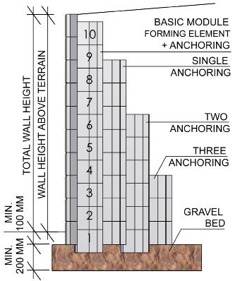
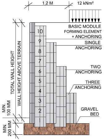
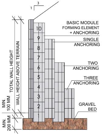
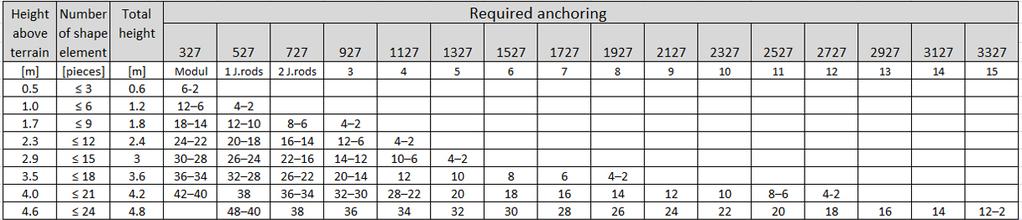
39 * table for FLAT and PONY Fig.a Fig.b Fig.c


40 ANNEX B DESIGN TABLES FOR STAVOBLOCK WALLS REINFORCED BY MEANS OF JOIN RODS Design tables for walls reinforced by join rods should serve to preliminary design of the wall. The tables are compiled for soil inner friction angle behind the wall ȹ 27, which can be generally considered for inner friction angle of loam-sand soil, which is most occurring soil. The tables are divided to three groups acc. to the terrain additional loading: Table of first group - applies for cases, when the terrain above the wall is flat or slightly sloppy with max. terrain slope 1:12, i.e. max. ca 5 Table of second group - applies for cases with additional loading above the wall of 12 knm-2 at distance ca 1 m from the face wall Table of third group - applies for cases, when the terrain above the wall is flat or slightly sloppy with max. terrain slope 1:3, i.e. max. ca 18 First column is the tables is wall height above the terrain (terrain height difference). Select in the table the wall height, which equals or exceeds the height of designed wall. Then the third column gives total height of wall, incl. wall underground part. Fourth column specifies number of anchoring join rod layers, the fifth column specifies their basic length. Height level of anchoring join rod positioning equals to upper face of numbered layers of the shape elements. The height levels are given in sixth (last) column. Numbering starts from the wall bottom - see wall diagram. Basic height of the face block equals 200 mm. The numbers stated in parenthesis apply for the FLAT and PONY blocks. INFORMATIVE DIMENSIONING TABLES FOR REINFORCED WALLS WITH FACE ELEMENTS TERRAIN ABOVE THE WALL IS FLAT OR GENTLY SLOPING WITH SLOPE MAX. 1 : 12 (Fig.d) TERRAIN ABOVE THE WALL IS FLAT WITH LOAD TO 12 knm2 (Fig.e)


41 TERRAIN ABOVE THE WALL IS SLOPING WITH SLOPE MAX. 1:3 (Fig.f) Note.: numbers in brackets are for FLAT and PONY. Fig.d Fig.e Fig.f

42 ANNEX C DESIGN TABLES FOR STAVOBLOCK WALLS REINFORCED BY MEANS OF GEOGRIDS Design tables for walls reinforced by geogrids should serve to preliminary design of the wall. The tables are compiled for soil inner friction angle behind the wall ȹ 27, which can be generally considered for inner friction angle of loam-sand soil, which is most occurring soil. The tables are divided to three groups acc. to the terrain additional loading: Table of first group - applies for cases, when the terrain above the wall is flat or slightly sloppy with max. terrain slope 1:12, i.e. max. ca 5 Table of second group - applies for cases with additional loading above the wall of 12 knm-2 at distance ca 1 m from the face wall Table of third group - applies for cases, when the terrain above the wall is flat or slightly sloppy with max. terrain slope 1:3, i.e. max. ca 18 First column is the tables is wall height above the terrain (terrain height difference). Select in the table the wall height, which equals or exceeds the height of designed wall. Then the third column gives total height of wall, incl. wall underground part. Fourth column specifies number of anchoring geogrid layers, the fifth column specifies their basic length. First reinforcing geogrid below the terrain is usually slightly longer than the other geogrids and its length is given in the sixth column. Height level of anchoring geogrid positioning equals to upper face of numbered layers of the shape elements. The height levels are given in seventh (last) column. Numbering starts from the wall bottom - see wall diagram. Basic height of the face block equals 200 mm. The numbers stated in parenthesis apply for the FLAT and PONY blocks. INFORMATIVE DIMENSIONING TABLES FOR REINFORCED WALLS WITH FACE ELEMENTS These tables can be used, when the soil inner friction angle behind the wall ȹ 27 and volumetric weight of naturally humid soil γ 19,5 knm-3. The values are typical for clays with low plasticity, loam, and loam with addition of sand (identification CL, ML, SC, SM). We presume gravel-sand reinforced soil (soil between reinforcing join rods). TERRAIN ABOVE THE WALL IS FLAT OR GENTLY SLOPING WITH SLOPE MAX. 1:12 (Fig.g)

 Note.")
43 TERRAIN ABOVE THE WALL IS FLAT WITH LOAD TO 12 knm2 (Fig.h) TERRAIN ABOVE THE WALL IS SLOPING WITH SLOPE MAX. 1:3 (Fig.ch) Note.: numbers in brackets are for FLAT and PONY.


44 Fig.g Fig.h Fig.ch ANNEX D AUXILIARY DRAIN SYSTEM OF REINFORCED WALLS STAVOBLOCK The auxiliary drainage system of the STAVOBLOCK reinforced walls includes blanket and stack drainage. The blanket drainage is usually made from the drainage material, which is located in horizontal direction below whole wall, i.e. at length of reinforcing join rods. Purpose of the blanket drainage is catching of ground water, which ascended up to the wall, and in addition removing of the water caught in the stack drain to the main drain pipe. The drainage material is usually protected by geo-textile filter against clogging with fine particles from adjacent soil. The stack drainage is usually performed in vertical direction between reinforced ground body and adjacent soil. The stack drainage can be made from drainage material, which is wrapped by fabric and/or it can be made from prefabricated drainage geo-composite. The stack drainage catches the water running from the soil behind the wall and prevents its penetration into reinforced ground body. The stack drainage is made to height of 70 % of the total wall

, which is protected from both sides by geo-textile filter, or the can be made from prefabricated drainage composite consisting from plastic core (e.g. webs of certain thickness) protected on both sides by geo-textile filter.")

45 height. The blanket and stack drainages are schematically shown on following figure: DRAINAGE PIPE 0,7 H - CHIMNEY DRAINAGE DRAINAGE COVER 150 MM Fig. D.1 Blanket and stack drainage: Possible realisation of the stack and blanket drainage The blanket and stack drainages can be made either from drainage material (e.g. gravel), which is protected from both sides by geo-textile filter, or the can be made from prefabricated drainage composite consisting from plastic core (e.g. webs of certain thickness) protected on both sides by geo-textile filter. The geo-composite plastic core is able to remove the water, the geo-textile filter prevents clogging of the drainage layer with fine particles of the loam / clay type. Due to their non-guaranteed pressure load capacity, it is recommended to use the geo- -composite drainages only to the stack drainages and to the height of 0.7 x H, where H is the wall height. Following figures show basic diagrams of both types. Fig. D.2 Drainage from classic drainage material: Fig. D.3 Drainage from prefabricated geo-composite:
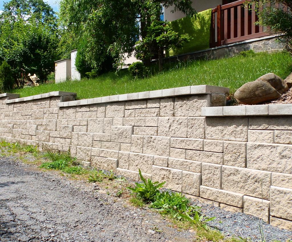
46
NOVEMBER 2016 GRANDWALL. retaining walls installation guide
 NOVEMBER 2016 GRANDWALL retaining walls installation guide RETAINING WALL INSTALLATION GUIDE RETAINING WALL information Austral Masonry Grandwall retaining wall blocks are an ideal choice for retaining
AUGUST 2017 HASTINGS. retaining walls installation guide
 AUGUST 2017 HASTINGS retaining walls installation guide RETAINING WALL INSTALLATION GUIDE RETAINING WALL information Austral Masonry retaining wall blocks are an ideal choice for retaining walls in gardens,
Construction Procedures
 Construction Procedures 2016 Rev. 1.7 1 Contents Introduction...... 3 Base Row Layout........ 4 Drainage and Backfill..... 6 Compaction... 7 Subsequent Rows... 8 In Pictures.... 10 Variations.. 11 Step
Construction Procedures
 Construction Procedures 2014 Rev. 1.6 1 Introduction This manual presents the methods and procedures necessary for the proper erection of a LOCK+LOAD retaining wall. problems later during the service life
PISA. Retaining Wall System. The choice of professional contractors
 PISA Retaining Wall System The choice of professional contractors PRODUCT CODE DESCRIPTION & DIMENSIONS (H x W x D) ~ WEIGHT PER UNIT No./M² No./ Lin M² UNITS PER PALLET 5501 Light Vertical Straight Unit
Retaining Wall System
 Your local distributor Retaining Wall System Prestige & Quality Near Vertical Walls Do It Yourself No Concrete Footings Flexible - 90 o Corners, Steps, Straight or Curved Walls Commercial or Civil Walls
Tasman Retaining Wall System
 Tasman Retaining Wall System The Tasman Retaining Wall System incorporates purpose made corners and capping units to provide classical reconstructed stone retaining walls for any landscape situation. From
Steps And Stairs Installation Steps In Wall - Option 1 Steps In Front of Walls - Option 2 Steps In Wall; 10 (25cm) Tread - Option 3 Step Parallel to
 Tread - Option 3 Step Parallel to") Steps And Stairs Installation Steps In Wall - Option 1 Steps In Front of Walls - Option 2 Steps In Wall; 10 (25cm) Tread - Option 3 Step Parallel to Wall - Option 4 Steps and Stairs Q & A E CONSTRUCTION
Steps And Stairs Installation Steps In Wall - Option 1 Steps In Front of Walls - Option 2 Steps In Wall; 10 (25cm) Tread - Option 3 Step Parallel to Wall - Option 4 Steps and Stairs Q & A E CONSTRUCTION
Features Include: Near Vertical Walls Do it Yourself No Concrete Footings Required
 Features Include: Near Vertical Walls Do it Yourself No Concrete Footings Required Tel: Office: +27 (0)11 964 2995 Fax number: +27 (0)86 601 6692 info@dsmmasonry.co.za www.dsmmasonry.co.za Range three
Steps And Stairs Installation Option 1 - Steps In Wall Option 2 - Steps With Plant Space Option 3 - Steps In Front of Walls Option 4 - Steps Along
 Steps And Stairs Installation Option 1 - Steps In Wall Option 2 - Steps With Plant Space Option 3 - Steps In Front of Walls Option 4 - Steps Along Wall Face Option 5 - Steps In Wall; 10 (25cm) Tread Option
Redi Rock Specification and Installation Manual
 Redi Rock Specification and Installation Manual 1.0 General Scope This Specification covers the Design, Materials and Installation of Redi Rock modular block Retaining and Freestanding Wall systems as
SPECIFICATIONS FOR PRECAST MODULAR BLOCK RETAINING WALL SYSTEM (revised 5/8/7)
") Page 1 of 7 STONE STRONG SYSTEMS SPECIFICATIONS FOR PRECAST MODULAR BLOCK RETAINING WALL SYSTEM (revised 5/8/7) PART 1: GENERAL 1.01 Description A. Work includes furnishing and installing precast modular
Page 1 of 7 STONE STRONG SYSTEMS SPECIFICATIONS FOR PRECAST MODULAR BLOCK RETAINING WALL SYSTEM (revised 5/8/7) PART 1: GENERAL 1.01 Description A. Work includes furnishing and installing precast modular
Anchorplex retaining wall construction guide. Building. Anchorplex. Retaining Wall Systems
 Anchorplex retaining wall construction guide Building Anchorplex Retaining Wall Systems Table of Contents and ow to Use This Guide table of contents ow to Use This Guide. 2 About the Anchorplex System.
Anchorplex retaining wall construction guide
 Anchorplex retaining wall construction guide Building Anchorplex Retaining Wall Systems Table of Contents and Introduction table of contents ow to Use This Guide......................... 2 About the Anchorplex
Tasman Retaining Wall System
 Tasman Retaining Wall System The Tasman Retaining Wall System incorporates purpose made corners and capping units to provide classical reconstructed stone retaining walls for any landscape situation. From
Building. Anchorplex. Retaining Wall Systems
 Building Anchorplex Retaining Wall Systems Table of Contents and Introduction table of contents ow to Use This Guide 2 About the Anchorplex System 2 Anchorplex System Material Specifications 3 Anchorplex
MagnumStone Specifications Gravity
 MagnumStone Specifications Gravity SPECIFICATION FOR MAGNUMSTONE GRAVITY MECHANICALLY STABILIZED EARTH SYSTEM PART 1: GENERAL.01Description The work consists of supplying and installing all aspects of
freestone eco Prestige & quality DIY vertical wall Large blocks - 10/m 2 Smooth surface finish No concrete footings
 freestone eco Retaining Wall SystemTM The Freestone ECO Retaining Wall System TM is a more sustainable DIY, vertical retaining wall which is manufactured with up to 40% recycled glass aggregate to provide
Garden WallScape Installation Guide
 By CornerStone Wall Solutions Inc. Garden WallScape Installation Guide GRAVITY/DETAILS The perfect balance... between design and nature Garden WallScape Overview note: bolded terms are defined in our online
STANDARD SPECIFICATION FOR CRIBLOCK CONCRETE CRIBWALL
 STANDARD SPECIFICATION FOR CRIBLOCK CONCRETE CRIBWALL 1. SCOPE 2. DESIGN 3. MATERIALS 4. CONSTRUCTION 5. METHOD OF MEASUREMENT AND PAYMENT SCOPE This Specification sets out requirements for the design,
GEOGRID CONNECTION DETAIL OLYMPIA RADIUS UNIT
 PLACE TWO STANDARD CONNECTORS IN EACH UNIT AS SHOWN (VERTICAL ORIENTATION) INSERT TWO CONNECTORS PER HORIZONTALLY ORIENTED BLOCK; INSERT ONE CONNECTOR PER VERTICALLY ORIENTED BLOCK SHIM BETWEEN BLOCK COURSES
SECTION MECHANICALLY STABILIZED EARTH RETAINING WALLS
 SECTION 13100 MECHANICALLY STABILIZED EARTH RETAINING WALLS PART 1 -- GENERAL 1.01 THE REQUIREMENT A. Includes all labor, material, equipment, testing and submittals required to design and complete construction
BELMURO WALL SYSTEM INSTALLATION GUIDE
 BELMURO WALL SYSTEM INSTALLATION GUIDE TABLE OF CONTENTS TABLE OF CONTENTS... 1 SYSTEM DESCRIPTION... 2 DRY STACK SYSTEM: INSTALLATION GUIDE... 5 GEOGRID WALL SYSTEM: INSTALLATION GUIDE... 9 MASONRY WALL
Bordeaux Walling. Product & Technical Information
 Product & Technical Information BORDEAUX WALLING Piece Piece Piece Block Block Block Block Pins No. per per Height Length Width Weight Layer Cube (kgs) 1 2 3 1 2 10 150 400/350 250 28 Yes 2 2 10 150 300/300
DRIVABLE GRASS GUIDELINE FOR DRIVABLE TURF INSTALLATION
 DRIVABLE GRASS GUIDELINE FOR DRIVABLE TURF INSTALLATION Please read through this instruction completely before beginning your installation. Be sure the proper equipment, and safety precautions are in place.
INTRODUCTION FEATURES DESIGN AND SPECIFICATION A. PROFESSIONAL DESIGN
 INTRODUCTION Terraforce & Terravert are a cost effective, segmented and mortarless retaining system which is fullly interlocking and truly plant supportive. The unit by itself or in combination with other
Every effort has been made to accurately represent the colors. However, the colors may vary slightly due to the concrete manufacturing process or
 1 Every effort has been made to accurately represent the colors. However, the colors may vary slightly due to the concrete manufacturing process or this printing process. We recommend viewing actual color
SECTION CONCRETE SEGMENTAL RETAINING WALL SYSTEM
 SECTION 02832 CONCRETE SEGMENTAL RETAINING WALL SYSTEM PART 1.: GENERAL 1.01 WORK INCLUDED A. This section includes the following: The Specifications on furnishing the design, materials and labor required
MACHINE-LAY Installation Manual
 MACHINE-LAY Installation Manual PaveDrain Installation Manual Table of Contents Section 1: Base Preparation (pages 3 6) Section 2: Machine-Lay PaveDrain Blocks (pages 8 11) Section 3: Edge Restraints (pages
LANDSCAPE RETAINING WALLS
 SUDAS Standard Specifications Division 9 - Site Work and Landscaping Section 9070 - Landscape Retaining Walls LANDSCAPE RETAINING WALLS PART - GENERAL.0 SECTION INCLUDES A. Modular Block Retaining Walls
A. Modular Unit - A concrete wall interlocking element, machine made from portland cement, water and aggregates.
 Section 02832 - Page 1 PART 1 - GENERAL 1.1 SUMMARY 1.2 DEFINITIONS 1.3 SUBMITTALS 1.4 JOB MOCK-UP A. This section includes furnishing and installation of modular interlocking concrete masonry units bearing
Retaining Walls. Made Easy
 Retaining Walls Made Easy Retaining Walls Made Easy! Contents Page 1 Contents Page 2 Foreword Page 3 Demolition Page 3 Removal Vegetation Page 3 Excavation Page 4 Reinforcement Steel Page 6 Concreting
SPECIFICATION FOR CORNERSTONE GEOGRID REINFORCED SEGMENTAL RETAINING WALL SYSTEM
 CornerStone Specifications Geogrid Reinforced SPECIFICATION FOR CORNERSTONE GEOGRID REINFORCED SEGMENTAL RETAINING WALL SYSTEM PART 1: GENERAL 1.01 Description The work consists of supplying and installing
TERRASTOP SYSTEM 2 RETAINING WALLS. Section Page 1 PART 1 - GENERAL 1.1 SUMMARY
 Section 02832 - Page 1 PART 1 - GENERAL 1.1 SUMMARY 1.2 DEFINITIONS 1.3 SUBMITTALS 1.4 JOB MOCK-UP A. This section includes furnishing and installation of modular interlocking concrete masonry units bearing
SPECIFICATIONS FOR PRECAST MODULAR BLOCK RETAINING WALL SYSTEM (revised 9/17/18)
") Page 1 of 8 STONE STRONG SYSTEMS SPECIFICATIONS FOR PRECAST MODULAR BLOCK RETAINING WALL SYSTEM (revised ) PART 1: GENERAL 1.01 Description A. Work includes furnishing and installing precast modular blocks
Page 1 of 8 STONE STRONG SYSTEMS SPECIFICATIONS FOR PRECAST MODULAR BLOCK RETAINING WALL SYSTEM (revised ) PART 1: GENERAL 1.01 Description A. Work includes furnishing and installing precast modular blocks
Gravity Wall. A force to be reckoned with... Gravity (SRW) segmental retaining wall systems are structures
 segmental retaining wall systems are structures") A force to be reckoned with... Gravity (SRW) segmental retaining wall systems are structures lower in height that use the FrogStone unit weight combined with gravel core infill to resist earth pressures
A force to be reckoned with... Gravity (SRW) segmental retaining wall systems are structures lower in height that use the FrogStone unit weight combined with gravel core infill to resist earth pressures
SPECIFICATION FOR PIPE CULVERT CONSTRUCTION
 SPECIFICATION FOR PIPE CULVERT CONSTRUCTION 1. SCOPE Pipe culverts shall be constructed in accordance with this specification and in conformity with the lines, levels and cross-sections shown on the drawings.
CONSTRUCTION SPECIFICATION FOR PRECAST REINFORCED CONCRETE BOX CULVERTS AND BOX SEWERS IN OPEN CUT
 ONTARIO PROVINCIAL STANDARD SPECIFICATION METRIC OPSS 422 APRIL 2004 CONSTRUCTION SPECIFICATION FOR PRECAST REINFORCED CONCRETE BOX CULVERTS AND BOX SEWERS IN OPEN CUT TABLE OF CONTENTS 422.01 SCOPE 422.02
G R A V I T Y / G E O G R I D
 GRAVITY/GEOGRID MAGNUMSTONE Overview note: bolded terms are defined in our online glossary at www.cornerstonewallsolutions.com The MagnumStone retaining wall system was developed with the installer in
Building Construction
 Building Construction Shallow Foundations Module-III Introduction The foundation can be classified broadly into two types: Shallow foundations Deep foundations Shallow foundations Shallow Foundations When
ARMOR-BLOCK. Installation guide. Installation Manual: ARMOR-BLOCK Retaining Wall System. Cap Block. Exposed void for planting.
 ARMOR-BLOCK Installation guide Cap Block Exposed void for planting In situ soil Engineered backfill Compacted and prepared base Setback Lip Ph 0800 655 00 or visit www.csppacific.co.nz 19 February 08 /
Retaining Wall Products
 Retaining Wall Products BCP Building Products 18 Kirkcaldy Street Bathurst NSW 2795 Phone 02 6331 2777 Fax 02 6331 6510 sales@bcpbuildingproducts.com.au www.bcpbuildingproducts.com.au Garden Lockstone
PENTABLOCK Technical Information 190mm Series
 PENTABLOCK Technical Information 190mm Series The PENTABLOCK Walling System was developed in consultation with masonry construction stakeholders with an aim of reducing labor time and material costs required
GRADING, FILL, EXCAVATION AND LANDSCAPING 2012 EDITION
 CHAPTER 23.105 GRADING, FILL, EXCAVATION AND LANDSCAPING 2012 EDITION Sections 23.105.101 General... 1 23.105.102 Definitions... 1 23.105.103 Permits required... 3 23.105.104 Hazards.... 4 23.105.105 Permit
Five Stone System. Trench Depth Compactible Rock. Foundation. 57 lbs 41 lbs 31 lbs 47 lbs. Patent Pending. Approximate Weight
 Five Stone System Patent Pending Introduction to the Multi-Use, Multi-Stone System The multi-use, multi-stone system has been developed to give a natural stone appearance to a manufactured system. The
Tasman Retaining Wall
 Tasman Retaining Wall EVALUATION AND INSTALLATION GUIDE Landscaping Tasman Retaining Wall Evaluation and Installation Guide This installation guide demonstrates the basics on how to construct: A. Tasman
GreenLock L9 Heavy Duty Retaining Wall Block (RWB) Features and advantages of the L9 retaining wall block
 Features and advantages of the L9 retaining wall block") GreenLock L9 Heavy Duty Retaining Wall Block (RWB) Features and advantages of the L9 retaining wall block 1. The L9 RWB has the ideal weight to size ratio and is designed to build strong, heavy duty and
GreenLock L9 Heavy Duty Retaining Wall Block (RWB) Features and advantages of the L9 retaining wall block 1. The L9 RWB has the ideal weight to size ratio and is designed to build strong, heavy duty and
On-Site Leaching Chamber Specifications & Features. Design & Installation Manual New York
 On-Site Leaching Chamber Specifications & Features Design & Installation Manual New York 1 This manual provides general design and installation information for use of Arc plastic leaching chambers in the
CITY OF SCHERTZ TEXAS ENGINEERING AND PUBLIC WORKS
 TEXAS STANDARD CONSTRUCTION NOTES DRWN. BY: DSGN. BY: KJW 1 of 2 *Place geotextile fabric as a permeable seperator to prevent mixing of coarse aggregate and underlying soil. (as needed). 1. GEOTEXTILE
SPECIFICATION FOR MAGNUMSTONE GEOGRID REINFORCED Mechanically Stabilized Earth (MSE) SYSTEM
 SYSTEM") MagnumStone Specifications Geogrid Reinforced SPECIFICATION FOR MAGNUMSTONE GEOGRID REINFORCED Mechanically Stabilized Earth (MSE) SYSTEM PART 1: GENERAL 1.01 Description The work consists of supplying
MagnumStone Specifications Geogrid Reinforced SPECIFICATION FOR MAGNUMSTONE GEOGRID REINFORCED Mechanically Stabilized Earth (MSE) SYSTEM PART 1: GENERAL 1.01 Description The work consists of supplying
Tasman and Norfolk Retaining Wall
 Tasman and Norfolk Retaining Wall Evaluation and Installation Guide BAINES We deliver Sydney s Best! Order online: bcsands.com.au Call: (02) 8543 3400 Taren Point & Mascot Tasman and Norfolk are registered
CONCRETE TILE PAVERS
 Section 32 14 13 CONCRETE TILE PAVERS (1995 MasterFormat Section 02780) Note: This guide specification for the U.S. is for the installation of concrete tile paving units whose thickness are less than the
SLAB ON GRADE Insul-Joint or Expansion Joint Material as Required by A/E Specifications AquaCheck Liquid Coating 400 (Waterproofing Membrane) with Aqu
 with Aqu") INSTALLATION INSTRUCTIONS Note: The following installation instructions are based off of ASTM E 1643 (Standard Practice for Installation of Water Vapor Retarders Used in Contact with Earth or Granular
INSTALLATION INSTRUCTIONS Note: The following installation instructions are based off of ASTM E 1643 (Standard Practice for Installation of Water Vapor Retarders Used in Contact with Earth or Granular
COUNTY BLOCK. Construction Guidelines on County Block Steps. Special Considerations When Building Steps. Natural Beauty Absolute Strength
 Construction Guidelines on County Block Limits of Liability This County Block Installation Guide provides general information about the product, including installation procedures, technical and engineering
2-16 EROSION, SEDIMENT & STORM WATER CONTROL REGULATIONS APPENDIX B1
 2-16 EROSION, SEDIMENT & STORM WATER CONTROL REGULATIONS APPENDIX B1 There are three ways to accomplish urban soil erosion and sedimentation control: Allow erosion to take place and then control sediment
SPECIFICATION FOR REINFORCED SOIL WALL
 SPECIFICATION FOR REINFORCED SOIL WALL 1.0 EXTENT OF WORK The work shall consist of Reinforced Soil walls built in accordance with this specification and in conformity with the lines, levels and details
DRIVABLE GRASS GUIDELINE FOR NON PLANTED DRY INFILL INSTALLATIONS
 DRIVABLE GRASS GUIDELINE FOR NON PLANTED DRY INFILL INSTALLATIONS Please read through this instruction completely before beginning your installation. Be sure the proper equipment, and safety precautions
CONCRETE SEGMENTAL RETAINING WALL SYSTEM
 CONCRETE SEGMENTAL RETAINING WALL SYSTEM PART 1: GENERAL SPECIFICATIONS 1.01 Work Included A. Work shall consist of furnishing and constructing a Rockwood Classic 8, Classic 6 and Legend unit segmental
Monumental Blok. Pallet Overview. Compatible caps. Notes. code 3521 (a) 3522 (b) 3523 (c) texture Chiseled. Specifications per pallet.
 3522 (b) 3523 (c) texture Chiseled. Specifications per pallet.") Monumental Blok code 3521 (a) 3522 (b) 3523 (c) texture Chiseled Pallet Overview (see below) HALF Specifications per pallet Imperial Metric Cubing 13.80 ft 2 /pal. (1.28 m 2 )/pal. 1.73 ft 2 /unit (0.16
Monumental Blok code 3521 (a) 3522 (b) 3523 (c) texture Chiseled Pallet Overview (see below) HALF Specifications per pallet Imperial Metric Cubing 13.80 ft 2 /pal. (1.28 m 2 )/pal. 1.73 ft 2 /unit (0.16
ITEM D-701 PIPE FOR STORM DRAINS AND CULVERTS
 ITEM D-701 PIPE FOR STORM DRAINS AND CULVERTS 701-1 DESCRIPTION 701-1.1 This item shall consist of the construction of pipe culverts, and storm drains, removal of existing storm pipes, connections to existing
h Installation Manual
 h Installation Manual 1 General Information The installation of HOBAS GRP Pipes is subject to applicable standards and guidelines such as EN 1610 and ISO/ TS 10465-1. Correct installation always requires
HUITEX GEOCELL INSTALLATION MANUAL
 Table of Contents 1 Site Preparation 2 Installation for the Retaining Wall 2.1 Base Preparation 2.2 Footing Installation 2.3 Placement of the Drainage System 2.4 Placement of the HUITEX Geocell panels
Construction Specification for Concrete Unit Pavers
 Engineering & Construction Services Division Standard Specifications for Road Works TS 3.80 September 2017 for Concrete Unit Pavers Table of Contents TS 3.80.01 SCOPE... 2 TS 3.80.02 REFERENCES... 2 TS
MODULO GEOBENT Installation Guidelines
 MODULO GEOBENT Installation Guidelines SUBGRADE PREPARATION The relative thinness of GCLs requires that more attention be given to subgrade preparation than should be given during the construction of a
Interiors Sources Decor LLC. Method Statement BLOCK WORK. Civil Works 6/26/2016
 Method Statement BLOCK WORK Civil Works 6/26/2016 The purpose of this Work Method Statement for Block Works (Concrete Masonry Units) is to outline and describe in detail the procedure such as setting and
shaped for imagination
 Installation Guide Straight or curved garden, retaining & seat walls steps pillars planters tree-rings fireplaces fire-pits water features grill islands BBQ s S-Shape Design shaped for imagination The
Reinforced Earth wall Construction Manual
 COVER PAGE CT-PE-W02 Rev: 5 Reinforced Earth wall Construction Manual Concrete Facing Reinforced Earth Malaysia Sdn Bhd 80-1, Jalan 8/62A Bandar Menjalara 52200 Kuala Lumpur Tel : 03-62746162, Fax : 03-62747212
INDEX FOR SPECIFICATIONS FOR REMOVING CULVERTS AND PLACING CULVERTS SCOPE... 1
 March 2002 No. 400 INDEX FOR SPECIFICATIONS FOR REMOVING CULVERTS AND PLACING CULVERTS 400. 1 SCOPE... 1 400. 2 REMOVING CULVERTS AND TIMBER STRUCTURES 2.1 Concrete and Metal Pipe Culverts... 1 2.2 Structural
Heron Retaining Walls
 Heron Retaining Walls masonry. build in style build in style Our range of coloured, standard and premium masonry have set a new standard in quality and style for the versatile concrete block. By adding
NOVEMBER 2016 MAGNUMSTONE. retaining walls installation manual
 NOVEMBER 2016 MAGNUMSTONE retaining walls installation manual AUSTRAL MASONRY CONTENTS Magnumstone Installation Guide 04 Overview 07 Unit Specifications 08 Installation 08 Gravity MagnumStone Wall 16 Geogrid
Retaining Wall Systems
 Retaining Wall Systems Construction & Quality Control Tensar Earth Technologies, Inc. Manual CONSTRUCTION & QUALITY CONTROL This manual provides general guidelines for construction and quality control
SECTION UTILITY BACKFILL MATERIALS
 SECTION 31 23 23 UTILITY BACKFILL MATERIALS PART 1: GENERAL 1.01 SECTION INCLUDES A. Material Classifications B. : 1. Concrete sand 2. Gem sand 3. Pea gravel 4. Crushed stone 5. Crushed concrete 6. Bank
Construction Specification for Utility Adjustments
 Engineering & Construction Services Division Standard Specifications for Road Works TS 4.50 September 2017 for Utility Adjustments Table of Contents TS 4.50.01 SCOPE... 2 TS 4.50.02 REFERENCES... 2 TS
PAVING SLABS ON A CONCRETE BASE
 SECTION 32 14 13.16 PAVING SLABS ON A CONCRETE BASE (1995 MasterFormat Section 02784) Note: This guide specification for the U.S. is for paving slabs on a sand bed over concrete for pedestrian applications.
INSTALLATION GUIDE A Unique Retaining Wall System That s Engineered to Last!
 INSTALLATION GUIDE A Unique Retaining Wall System That s Engineered to Last! Safety Safety is the number one concern of Big Block, Inc. It s of utmost importance that Big Block walls be installed in a
VERSA-Green TM Plantable Retaining Wall System
 www.versa-lok.com VERSA-Green TM Plantable Retaining Wall System VERSA-GREEN INSTALLATION The VERSA-Green Plantable Wall System from VERSA-LOK is truly the greenest retaining wall available. It combines
SECTION Segmental Concrete Unit Masonry Retaining Wall Height Over 5-0 High
 PART 1: GENERAL 1.0 0 Scope of Standards A. This standard provides general guidance concerning the specific preferences of the Texas State University for a Segmental Retaining Wall up to 5-0 high. B. Texas
GRANDE WALL large CONCRETE BLOCKS FOR THE CONSTRUCTION OF RETAINING WALLS. 1339_Feuillet_Permacon_Grande_ang.indd 1
 GRANDE WALL large CONCRETE BLOCKS FOR THE CONSTRUCTION OF RETAINING WALLS 1339_Feuillet_Permacon_Grande_ang.indd 1 27-05-15 14:03 GRANDE WALL The Grande wall system is designed for building retaining walls
Installation Information 2018
 Installation Information 2018 DENDRO-SCOTT Root Barrier... why use anything else? DENDRO-SCOTT Root Barrier, recognised by the Environment Agency, is known for its quality and reliability. It is flexible
Installation Manual. Foundations. Version 2
 Installation Manual Foundations Version 2 Contents Overview...1 Planning the Job... 2 Introducing DMX FlexSheet...2 Supplies Required...3 Tools Required...4 Preparing the Site...4 Where to Start?...5 Installing
FREESTONE ECOTM. Retaining Wall SystemTM. No one knows Blocks and Pavers better
 FREESTONE ECOTM Retaining Wall SystemTM The Freestone ECO Retaining Wall System TM is a more sustainable DIY, vertical retaining wall which is manufactured with up to 40% recycled glass aggregate to provide
Installation Information 2016
 Installation Information 2016 DENDRO-SCOTT Root Barrier... why use anything else? DENDRO-SCOTT Root Barrier, recognised by the Environment Agency, is known for its quality and reliability. It is flexible
SECTION A1 EXCAVATION AND BACKFILL GENERAL
 SECTION A1 EXCAVATION AND BACKFILL GENERAL The work under this section shall include all excavation to such width and depth as shown on the drawings, specified herein, or ordered by the Engineer. Such
Corners VERSA-LOK solid concrete units may be easily used to create an unlimited variety of corners. Basic Wall Design Elements.
 Landscape Steps Landscape Steps Size Pieces per Pallet Weight per Piece Weight per Pallet 6 x 16 x 48 10 420 4200 6 x 16 x 36 10 300 3000 Colors: Brown & Grey Basic Wall Design Elements Half units on outside
PYZIQUE FRESTANDING & RETAINING WALL
 PYZIQUE FRESTANDING & RETAINING WALL 120 Cambridge Wall Book Pyzique Cambridge Wall Book 121 Pyzique Wall PYZIQUE WALL ONE STONE DOES IT ALL! The Trapezoid shape (4 in. high x 9in. deep x 11 in. and 7
SECTION SPECIFICATION FOR MECHANICALLY STABILIZED EARTH TWO STAGE WALL SYSTEM
 SECTION 02830 SPECIFICATION FOR MECHANICALLY STABILIZED EARTH TWO STAGE WALL SYSTEM ## THIS SECTION IS WRITTEN IN CSI 3-PART FORMAT AND IN CSI PAGE FORMAT. NOTES TO THE SPECIFIER, SUCH AS THIS, ARE INDICATED
SECTION TRENCHING, BACKFILLING, COMPACTION AND GENERAL GRADING
 PART 1 GENERAL SECTION 02221 TRENCHING, BACKFILLING, COMPACTION AND GENERAL GRADING 1.01 SECTION INCLUDES A. Excavation, dewatering and backfilling with compaction of trenches for pipes, conduits, channels
EDGE RESTRAINT SYSTEM
 EDGE RESTRAINT SYSTEM Whether its decorative block paving or precast flags, alternate edge restraint systems are taking the world of paving by storm and IrandiPRO is South Africa s first such system. Proudly
SECTION TRENCHING
 SECTION 31 23 17 TRENCHING PART 1 GENERAL 1.1 SUMMARY A. Section Includes: 1. Excavating trenches for utilities and utility structures. 2. Bedding. 3. Backfilling and compacting to subgrade elevations.
Michigan State University Construction Standards SEGMENTAL CONCRETE RETAINING WALLS PAGE SECTION SEGMENTAL CONCRETE RETAINING WALLS
 PAGE 323223-1 SECTION 323223 PART 1 - GENERAL 1.1 RELATED DOCUMENTS A. Drawings and general provisions of the Contract, including General and Supplementary Conditions and Division 01 Specification sections,
CONTENT. INTrOduCTION 3. units & CONNECTOrs 4. standard INsTallaTION PrOCEdurEs 5
 CONTENT INTrOduCTION 3 units & CONNECTOrs 4 standard INsTallaTION PrOCEdurEs 5 step 1 - Preconstruction Preparation 5 step 2 - Prepare the leveling Pad 5 step 3 - Install the Base Course 5 step 4 - Geogrid
Palm Retaining Walls. masonry. build in style
 Palm Retaining Walls masonry. build in style build in style Our range of coloured, standard and premium masonry have set a new standard in quality and style for the versatile concrete block. By adding
Installation guide WALLS
 WALLS Installation outline 6" (150 mm) min. 6" (150 mm) min. 12" (300 mm) min. 6" (150 mm) min. 01 EXCAVATION A. Check the location of existing structures and utilities before starting the excavation.
Installation guide WALLS
 WALLS Installation outline 6" (150 mm) min. 6" (150 mm) min. 12" (300 mm) min. 6" (150 mm) min. 01 EXCAVATION A. Check the location of existing structures and utilities before starting the excavation.
Installation Guidelines
 815 NE 172 nd Avenue Vancouver, WA 98684 877-694-0141 Installation Guidelines Installation steps include job planning, layout, excavating and preparing the soil subgrade, applying geotextiles (optional),
SERIES 1100 KERBS, FOOTWAYS AND PAVED AREAS
 MANUAL OF CONTRACT DOCUMENTS FOR HIGHWAY WORKS VOLUME 1 THE SPECIFICATION FOR HIGHWAY WORKS SERIES 1100 KERBS, FOOTWAYS AND PAVED AREAS Contents Clause Title Page 1100 (02/17) General 2 #1101 Precast Concrete
CONSTRUCTION SPECIFICATION FOR PRECAST REINFORCED CONCRETE BOX CULVERTS AND BOX SEWERS IN OPEN CUT
 ONTARIO PROVINCIAL STANDARD SPECIFICATION METRIC OPSS 422 APRIL 2004 (Reissued November 2010) CONSTRUCTION SPECIFICATION FOR PRECAST REINFORCED CONCRETE BOX CULVERTS AND BOX SEWERS IN OPEN CUT TABLE OF