Firms may request consideration by submitting a letter of interest and completed TDOT Form DT0330, Part I & II to:
|
|
|
- Patrick Wade
- 5 years ago
- Views:
Transcription
1 NOTICE TO CONSULTANT ENGINEERS REGARDING A REQUEST FOR LETTERS OF INTEREST April 1, 2018 The City of Knoxville, an Equal Opportunity/Affirmative Action Employer, seeks to retain the services of a professional engineering consulting firm or team of firms with extensive experience in roadway design, structural design, and railroad coordination to provide professional design services to prepare bid specifications, contract documents, and construction plans for the Amherst Road Slope Stabilization Project. The City of Knoxville intends to stabilize the south side of Amherst Road between 1950 Amherst Road and 2004 Amherst Road. The project will re-establish the roadway shoulder including the installation of guardrail and retaining wall within CSX railroad right-of-way. Results of previous subsurface exploration in this section of roadway shoulder and slope leading down to the railroad tracks are included with this solicitation on the Purchasing Division s website as background information. The scope of service for this project will include survey, design, and preparation of bid specifications, contract documents, and construction drawings. The City of Knoxville will require interested firms have successfully completed roadway and structural design projects in the last five (5) years and provide information about these projects in their proposal. This project is funded locally by the City of Knoxville and not with Federal of State funds. As such, firms are not required to be Pre-Qualified by TDOT. However, in the interest of uniformity of submissions and simplicity in comparison/evaluation of the submissions, the City does require that submitters provide their statements of qualifications in the TDOT format. With this in mind, the City will require six (6) copies of TDOT prequalification forms DT0330, Parts I & II be completed and submitted with the letter of interest. The TDOT Form DT-0330 Parts I & II may be found on the Internet at: Firms may request consideration by submitting a letter of interest and completed TDOT Form DT0330, Part I & II to: City of Knoxville Office of the Purchasing Agent City County Building, Suite Main Street Knoxville, TN Letters of interest shall indicate the anticipated scope of services to be completed by subcontractors. All letters of interest must be received on or before 11:00 AM (Eastern Time) Friday, April 27, Late submissions will not be considered.
2 For additional details regarding this project, please visit the Purchasing Division's website at under "Sealed Submissions." All questions must be submitted in writing by end of business day April 20, 2018 to Mr. Boyce Evans, Purchasing Agent by letter, at or fax (865) The factors that will be considered in evaluation of submissions are: a. Qualifications, relevant experience, past experience with the City of Knoxville, TDOT and other clients, especially as it relates to roadway design, structural design, and railroad coordination. (25%) b. Availability of staff to be assigned to work on this project. (25%) c. Demonstrated ability to meet schedules and perform work efficiently without compromising sound engineering practice. (25%) d. Evaluations on prior projects. (20%) e. Amount of work currently under contract with the City of Knoxville. (5%) Evaluation proceedings will be conducted within the established guidelines regarding equal employment opportunity and nondiscriminatory action based upon the grounds of race, color, religion, national origin, sex, creed, age, and disability. Interested certified Disadvantaged Business Enterprise (DBE) firms as well as other minority and/or women-owned firms are encouraged to respond to all advertisements by the City. City of Knoxville, Tennessee Date Purchasing Agent
3 Subsurface Exploration Amherst Road Slope Stability Investigation Knoxville, Tennessee 5/10/2016 FSE Project No Prepared For: City of Knoxville


4 May 10, 2016 Mr. Shawn E. Fitzpatrick, P.E. City of Knoxville Department of Engineering Civil Division 1400 Loraine Street Knoxville, Tennessee RE: Subsurface Exploration Amherst Road Slope Stability Investigation Knoxville, Tennessee FSE Project No Dear Mr. Fitzpatrick: As authorized by your acceptance of our proposal dated May 20, 2015, we have completed a subsurface exploration of the slope on the south side of Amherst Road, located approximately between 1950 and 2004 Amherst Road. The section of slope that was investigated is approximately 540 feet in length. The purpose of the exploration was to provide engineering recommendations for stabilization/repair of the south side of the road (shoulder) and slope leading down to the CSX rail line. The firms of Foundation Systems Engineering, P.C. and Construction Materials Laboratory completed this work. Please give us a call if you have any questions concerning the data obtained or our recommendations. It has been a pleasure to be of service on this project. Sincerely, Foundation Systems Engineering, P.C. 05/10/2016 Eric M. Peterson, P.E. Jack F. Llewellyn, Jr., P.E. Geotechnical Engineer Principal-In-Charge Tennessee No Tennessee No JFL/EMP/sf Enclosures
5 TABLE OF CONTENTS 1.0 EXECUTIVE SUMMARY OBJECTIVE OF SUBSURFACE EXPLORATION SCOPE OF SERVICES SITE LOCATION AND CONDITIONS SUBSURFACE STRATIFICATION Drilling And Sampling Procedures Soil Overburden Soil Overburden Ground Water GEOLOGY LABORATORY TESTING Atterberg Limits And Natural Moisture Content Triaxial Shear Test Data Summary SLOPE STABILITY ANALYSIS RECOMMENDATIONS Roadway Preparation Pavement Repair Erosion Control Measures ESTIMATED COSTS ADDITIONAL RECOMMENDED WORK GENERAL QUALIFICATIONS... 22
6 LIST OF APPENDICIES I. Typical Cross Section II. Slope Stability Analysis - Slide v. 5.0 III. Gabion Wall Analysis - GawacWin 2003 IV. Boring Location Plan & Auger Boring Records V. Laboratory Test Results a. Atterberg Limits b. Natural Moisture Content c. Triaxial Shear Test VI. ASFE
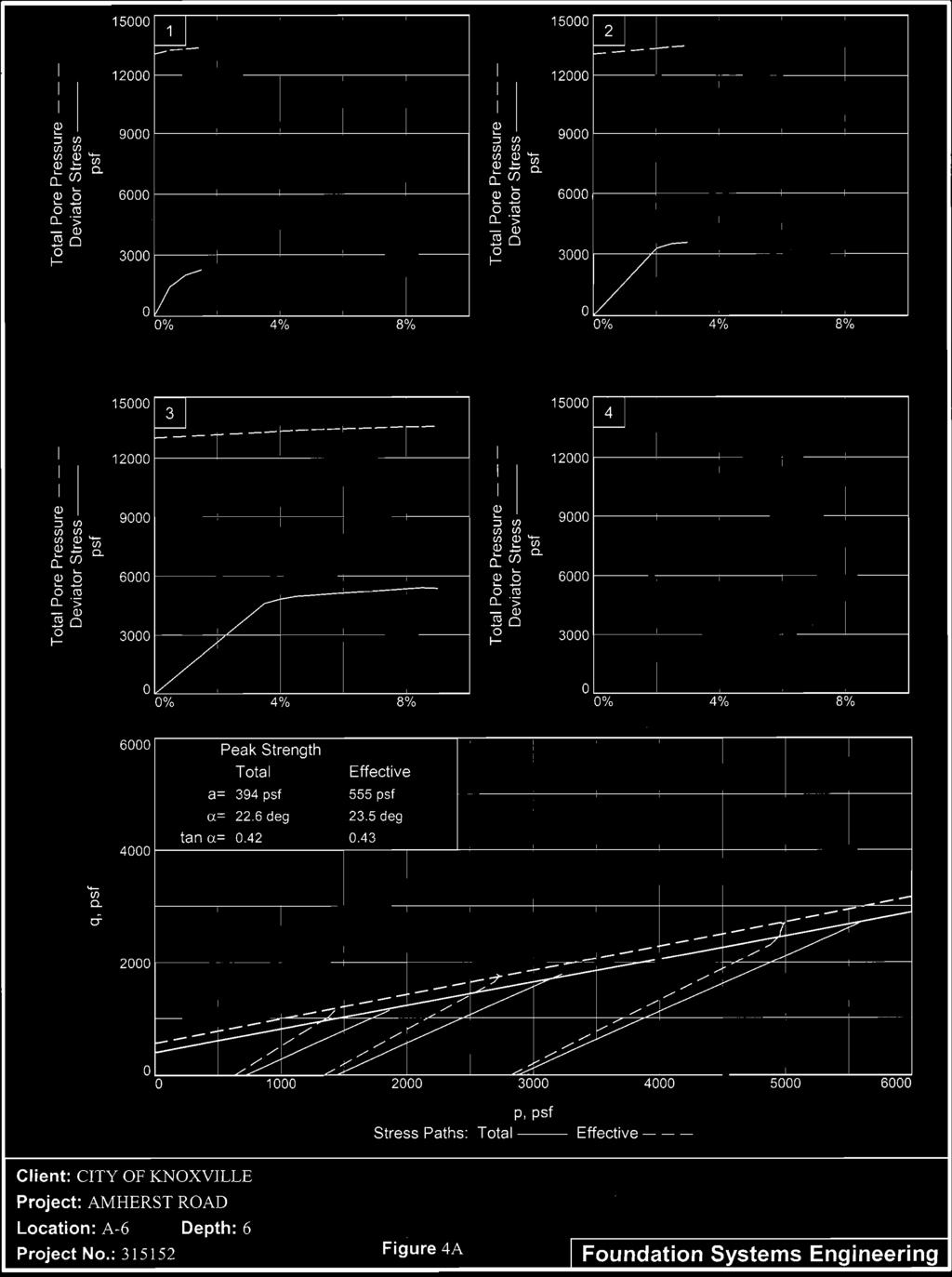
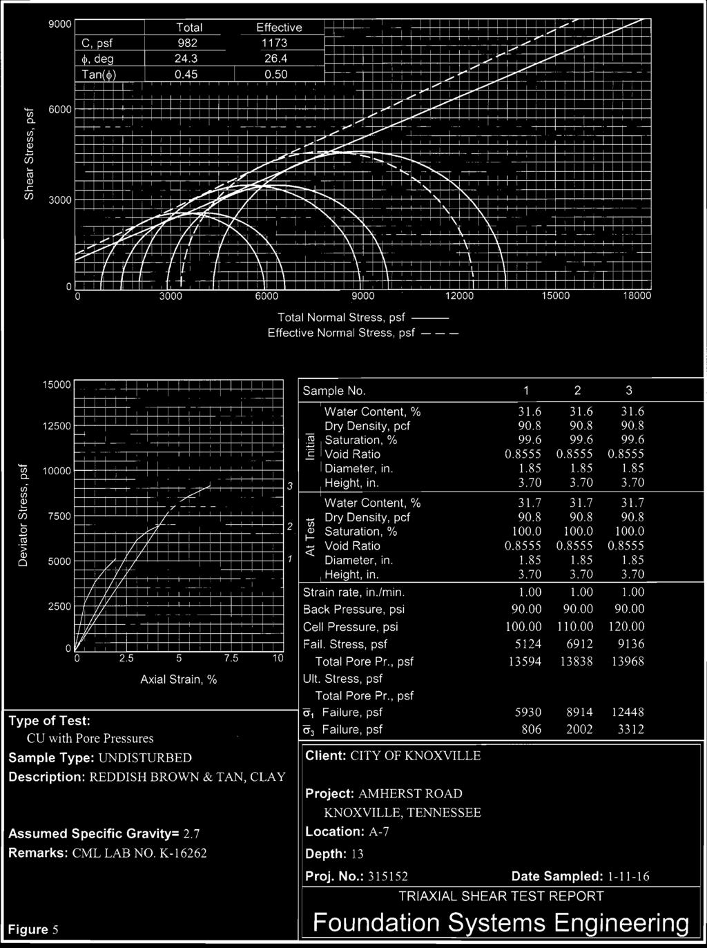
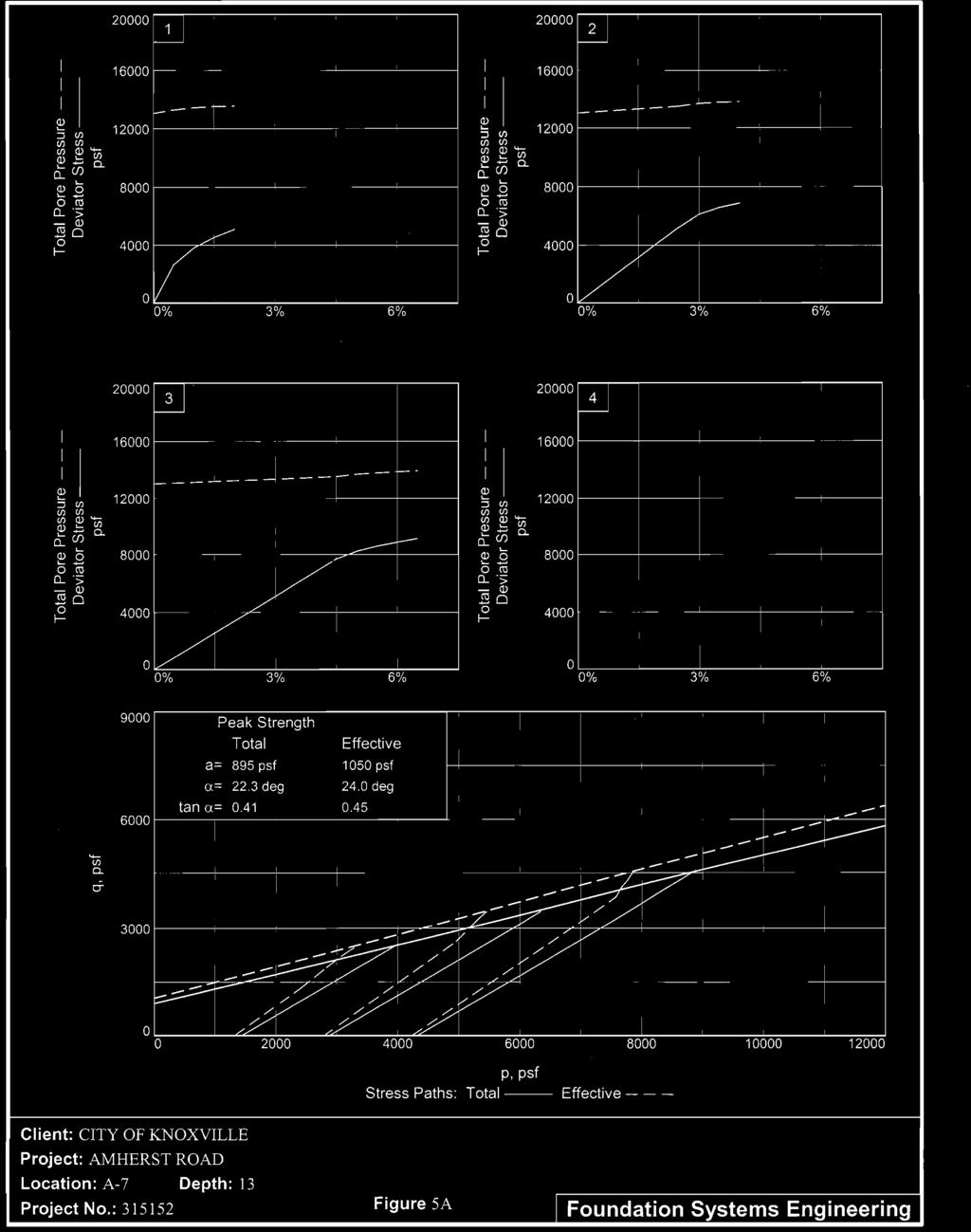
7 Mr. Shawn Fitzpatrick, P.E. May 10, 2016 Page EXECUTIVE SUMMARY The focus of this subsurface exploration is the section of roadway shoulder and slope leading down to an existing CSX railroad track, located on the south side of Amherst Road. The section of roadway that was explored was between the addresses of 1950 Amherst Road and 2004 Amherst Road. Within this area, several slope face failures have occurred resulting in the loss of the roadway shoulder, including a loss of a portion of the roadway pavement at locations. In order to investigate the stability of the slope, seven soil borings (A-1 through A-7) with Dynamic Cone Penetrometer testing and undisturbed Shelby tube sampling, were placed at the site. The borings were drilled to depths of 25 to 30 feet below existing grade or auger refusal. Laboratory plasticity, natural moisture content, and triaxial shear testing was performed on selected samples within the laboratory to determine soil plasticity and strength characteristics. In general, the borings encountered approximately 4 to 4.5 inches of asphalt pavement at existing grade. The pavement was typically underlain by a combination of limestone aggregate base, limestone gravel, and/or additional layers of pavement. The limestone gravel was typically mixed with soil. Fill soils were encountered beneath the pavement and base at three of the boring locations (A-3, A-4, and A-6), ranging in depth from approximately 9 feet to approximately 22 feet below existing grade. The consistency of the fill at borings A-3 and A-4 was firm to stiff, whereas A-6 was soft to firm. Residual soils were encountered beneath the base and/or fill at each of the boring location. The consistency of the residual soil was typically stiff to hard. Borings A-1 and A-3 refused at depths of 7.5 feet and 13 feet below existing grade, respectively. All remaining borings were terminated at their predetermined drill depth of 25 or 30 feet. The soil samples selected for testing are classified under the Unified Soil Classification System (USCS) as inorganic clays of low to medium plasticity (CL), high plasticity clays (CH) and inorganic silts (ML). The result of the Atterberg limits testing indicates that the soil liquid limit values for the samples selected for testing varied from approximately 22 percent to approximately 56 percent, with an average of approximately 39 percent. Soil plastic limit values varied from approximately 12 percent to approximately 30 percent, with an average soil plastic limit value of was approximately 22 percent. Soil natural moisture content values varied from approximately 11.4% to approximately 34.8%. Five of the soil samples obtained from the Shelby tube sampling were selected for consolidated, undrained, effective stress triaxial shear testing. The triaxial shear testing
8 Mr. Shawn Fitzpatrick, P.E. May 10, 2016 Page 2 was performed to determine the strength parameter of the soil, including soil unit weight, friction angle, and cohesion. The results of the triaxial shear testing were used for slope stability analysis for the slope located on the south side of Amherst Road, between the road and CSX rail line. Slope stability analysis was completed using Slide (version 5.044) 2D Limit Equilibrium Slope Stability Analysis Software by Rocscience, Inc. Three typical cross sections of the existing site was adapted from topographic data collected at the site by our firm. The existing slope geometry at each of the three cross sections along with estimated traffic loading was used in our analysis. Subsurface data utilized in our analysis is based on data obtained from site reconnaissance, soil auger borings, laboratory plasticity testing, and triaxial shear testing. The stability of slopes is discussed in terms of factor of safety values. Factor of safety values are the ratio of the soil driving force to the soil resisting force. We recommend that a Factor of Safety of >1.5 be utilized for minimum allowable slope stability. This recommendation considers that the slope provides support to a roadway, and slope failure could encroach onto CSX rail lines. The results of our stability analysis indicated factor of safety values with respect to global slope stability ranging from to In our professional opinion the results of the testing performed indicate that the slope is stable with respect to mass instability. A global slope failure is not predicted to occur. However, we did observe raveling and sluffing of the slope surface (slope face failures). There are sections where the shoulder and edge of the paved portion of the road have been lost. As such, while the slope is stable with regard to mass movement, loss of the roadway due to erosion and sluffing of the exposed outer surface material is occurring. We recommend the use of Gabion baskets to re-establish the roadway shoulder and protect the roadway from additional shoulder failures. In general, we recommend the following procedures be performed: We recommend that the southernmost (eastbound) traffic lane and proposed shoulder area be undercut down to firm, stable soil. We estimate undercut depths ranging from approximately 3 feet to approximately 6 feet below finished subgrade elevation in order achieve a suitable bearing surface area for the Gabion baskets. The temporary construction excavation behind the wall should be sloped no steeper than 0.5H to 1V, or otherwise braced. Once the required undercut has been performed, the upper 6 inches of the in-place soil at the undercut level should be reworked and recompacted. Fine grading
9 Mr. Shawn Fitzpatrick, P.E. May 10, 2016 Page 3 should be performed as necessary to ensure that the area has been adjusted to the proper elevation. The bottom and sides of the excavation should be lined with a minimum 8-ounce per square yard weight non-woven geotextile. The Gabion baskets should be constructed, filled, and set into place as per the Gabion basket manufacturer s specifications, and City of Knoxville technical specifications. A drain, consisting of a perforated pipe, surrounded by No. 57 sized stone, with stone and pipe encased in a non-woven drainage geotextile, should be placed behind the baskets to ensure no ponding of water occurs. Once the Gabion baskets have been constructed up to finished subgrade elevation as outlined above, the roadway undercut/backfilled area should be covered with a high modulus geotextile. The geotextile should be covered with 4 inches of No. 57 stone, compacted to 95%. The roadway should be repaved utilizing 8 thickness of TDOT 303D aggregate base, 3 thickness of TDOT 307BM Asphalt Base Course, and 1.5 thickness of TDOT 411D Asphalt Surface Course. The guardrail may be reinstalled and anchored into the Gabion shoulder utilizing a formed (sono-tube) concrete base. The remaining slope located south (down gradient) of the Gabion baskets and roadway should be protected from erosion utilizing a turf reinforcement mat, such as Propex TRM The attached sketch graphically depicts the above outlined recommendations. Based on the results of the subsurface exploration, preliminary design work, and similar past projects, we estimate the cost for construction, construction administration, and quality control services for the above outlined recommendations to be approximately $357, This estimate does not include the costs of permits, flagmen, insurance, etc. that will be required by the CSX railway. Based on our familiarity with the site and the geotechnical considerations present, we believe that we are uniquely qualified to provide construction observation services during site grading and future building construction. We recommend that our firm be retained to provide quality control testing and observation services during construction. The above summary provides an overview only and should not be used as a separate document or in place of reading the entire report including the appendices. The summary is not a substitute for the following detailed sections of this report. A complete discussion of finding and recommendations are included in the following sections of this report.
10 Mr. Shawn Fitzpatrick, P.E. May 10, 2016 Page OBJECTIVE OF SUBSURFACE EXPLORATION The purpose of our exploration was to gather subsurface data to allow geotechnical engineering recommendations for repair of the Amherst Road south roadway shoulder and stabilization of the roadway slope leading down to a CSX railroad line. The section of roadway that was explored was between the addresses of 1950 Amherst Road and 2004 Amherst Road. To meet the objectives of the subsurface exploration, seven soil borings with Dynamic Cone Penetrometer testing and undisturbed Shelby tube sampling, were placed along the subject section of the roadway. The boring locations were identified/located in the field by our personnel. The borings were drilled to depths of 25 to 30 feet below existing grade or auger refusal. Laboratory plasticity, natural moisture content, and triaxial shear testing was performed to determine soil plasticity and strength characteristics. 3.0 SCOPE OF SERVICES Seven (7) soil auger borings with Dynamic Cone Penetrometer (DCP) testing were used to investigate the section of Amherst Road where the south roadway shoulder and slope leading down to the CSX rail line have experienced surface failure and sluffing. The borings were placed at locations as selected by our personnel. The borings were drilled to depths of 25 to 30 feet below existing grade, or auger refusal. The approximate locations of the borings may be seen on the attached Boring Location Plan. Upon completion, the borings were backfilled with concrete. Dynamic Cone Penetrometer (DCP) testing, ASTM STP 399, was performed at 2.5 foot intervals to a depth of 10 feet below existing grade. Below a depth of 10 feet the penetrometer testing was performed at 5 foot intervals to auger refusal or proposed boring termination depth. Twenty-three (23), 2-inch diameter, undisturbed, Shelby tube samples of the in-place soils were collected from the site as the borings were advanced. The Shelby tubes were sealed in the field and transported to the laboratory, at which location the soil was extruded from the tubes. The undisturbed samples were visually classified by an engineer. The locations and depths at which the undisturbed samples were taken may be seen in Table II of this report.
11 Mr. Shawn Fitzpatrick, P.E. May 10, 2016 Page 5 A drilling log was prepared by a geotechnical engineer for the borings. The logs include the results of the DCP testing, Shelby tube sampling intervals, groundwater levels, and soil stratification with description. Five (5) Atterberg limits and seventeen (17) natural moisture content determination tests were performed on selected samples of soil encountered at the boring locations. The Atterberg limits and moisture testing was performed to determine soil plasticity characteristics. The results of the Atterberg Limits test may be seen in Table III of this report, and the results of the natural moisture content testing may be seen in Table IV of this report. Laboratory Atterberg limits and natural moisture content data sheets may be found in the report appendix. Five (5) consolidated, drained, effective stress, triaxial shear tests were performed on undisturbed samples of soil encountered as the borings were advanced. The triaxial shear test samples were selected from samples collected during undisturbed Shelby tube sampling. The results of the triaxial shear testing may be seen in Table V of this report. Laboratory triaxial shear test data sheets may be found in the report appendix. A brief summary of the test procedures utilized on this project are located in the Appendix of this report. 4.0 SITE LOCATION AND CONDITIONS Amherst Road parallels the CSX Railway for approximately 600 feet between the addresses of 1950 Amherst Road and 2004 Amherst Road. This section of the roadway is located on the Railroad right-of-way. Topographically, the roadway is situated at the crest of a steep slope, at an elevation of approximately 15 to 20 feet above the railroad. The slope was measured to be sloped at an angle ranging from approximately 1.4H:1V to approximately 0.75H:1V. Steeper or gentler grades may be located between the measurement locations. Slope surface failures along the southern edge of the roadway have left little to no shoulder. In some areas, the failures have extended into the roadway, undermining and failing the pavement. Some temporary measures have been taken to stabilize the shoulder in these areas, including the use of guardrail posts (as piling), guardrails (as lagging), and sacks of concrete mix.
12 Mr. Shawn Fitzpatrick, P.E. May 10, 2016 Page Drilling And Sampling Procedures 5.0 SUBSURFACE STRATIFICATION Seven soil auger borings (A-1 through A-7) were used to investigate the subject section of Amherst Road. The borings were placed using a Bobcat T 200 skid steer with auger head attachment. Dynamic Cone Penetrometer (DCP) testing, ASTM STP 399, was performed through nominal 8-inch diameter Hollow-stem augers as the borings were advanced. A brief summary of the soils encountered at the boring locations follows. Additional subsurface details may be seen on the attached Auger Boring Records. Subsurface stratification indicated on the boring logs is approximate, and represents our interpretation of the soils encountered in the borings at the Shelby tube sampling intervals and on soil auger cuttings returned to the surface on the auger flights. DCP testing was typically performed at 2.5-foot intervals to a depth of 10 feet below existing grade. Thereafter DCP testing was performed at 5-foot intervals. Twenty-three, 2-inch diameter, undisturbed, Shelby tube samples of the in-place soils were collected at the site as the borings were advanced. The locations and depths at which undisturbed Shelby tube sampling and DCP testing was performed may be seen on the attached Auger Boring Records. The boring depths and approximate ground surface elevation at each of the boring locations may be seen in the following table. Table I Boring Data Summary Boring Number Surface Elevation Drill Depth, Ft. Boring Number Surface Elevation Drill Depth, Ft. A R A T A T A T A R A T A T Elevation interpolated from topographic map. T = Terminated. R = Refusal The locations and depths at which the Shelby Tube samples were taken may be seen in the following table.
13 Mr. Shawn Fitzpatrick, P.E. May 10, 2016 Page 7 Table II Shelby Tube Sample Locations Boring Number Shelby Tube Depth, Ft. Boring Number Shelby Tube Depth, Ft. A A A A A A A A A A A A A A A A A A A A A A A Soil Overburden The subsurface stratification indicated on boring logs is approximate, and was developed by a geotechnical engineer based on his interpretation of the driller s field log, soil auger cuttings returned to the ground surface on auger flights, and on undisturbed Shelby tube sampling. The soil test borings were drilled vertically. The data indicated on the boring logs, and as summarized in the abbreviation below, indicates the findings at the boring locations only. The typical boring cross sections accompanying the boring logs is generalized, and briefly summarizes graphically the material encountered at the boring locations. The ground surface elevation indicated on boring logs is approximate. Following is a brief summary of the soils encountered at the boring locations. 5.3 Soil Overburden Boring A-1 encountered approximately 4 inches of asphalt pavement at existing grade. The asphalt pavement is underlain by approximately 20 inches of alternating layers of aggregate base and asphalt pavement. Residual soil was encountered beneath the aggregate base/asphalt layers. The residual soils have been derived from the in-place weathering of the underlying bedrock unit. From a depth of approximately 2 feet (24
14 Mr. Shawn Fitzpatrick, P.E. May 10, 2016 Page 8 inches) to a depth of approximately 7.5 feet, stiff to very stiff, moist, tan, reddish tan and reddish brown, silty clay mixed with chert was encountered. The augers refused at a depth of 7.5 feet below existing grade. No groundwater was encountered at the time of drilling. Boring A-2 encountered approximately 4.5 inches of asphalt pavement at existing grade. The asphalt pavement is underlain by approximately 7.5 inches of limestone base mixed with moist, brown silty clay. Residual soil was encountered at a depth of approximately 12 inches. The residual soil consists of very stiff to hard, moist, tan, reddish tan, and reddish brown, silty clays. The boring was terminated at a depth of 30 feet below existing grade. No groundwater was encountered at the time of drilling. Boring A-3 encountered approximately 4 inches of asphalt pavement underlain by approximately 14 inches of crushed limestone base mixed with broken asphalt and topsoil. Fill soils were encountered at a depth of approximately 18 inches below grade. The fill soils were encountered to a depth of approximately 9 feet below existing grade. The fill soils consist of firm to stiff, moist, tan and reddish brown, silty clay. Residual soil was encountered at a depth of approximately 9 feet. The residual soil consists of very stiff, moist, tan and reddish brown, silty clay. The augers refused at a depth of 13 feet. No groundwater was encountered at the time of drilling. Boring A-4 encountered approximately 4 inches of asphalt pavement underlain by approximately 5 inches of crushed limestone aggregate base. The aggregate base course was underlain by approximately 9 inches of limestone gravel mixed with gray and black, organic, silty clay. Soil fill was encountered beneath the soil/gravel mixture. The fill soils consist of stiff, very moist to moist, tan and reddish brown, silty clay mixed with chert. Residual soil was encountered at a depth of approximately 15 feet. The residual soil consists of stiff, moist, tannish gray, tan and reddish tan, silty clay mixed with chert. Boring A-4 was terminated in very stiff residual soil at a depth of 30 feet below existing grade. No groundwater was encountered at the time of drilling. Boring A-5 encountered approximately 4.5 inches of asphalt pavement at existing grade. The asphalt pavement was underlain by approximately 7.5 inches of crushed limestone aggregate base mixed with moist to very moist, gray and black, organic, silty clay. Residual soil was encountered at a depth of approximately 12 inches below existing grade. From a depth of approximately 12 inches to a depth of approximately 25 feet, stiff to very stiff, moist, tan, reddish tan and reddish brown, silty clay mixed with fine to coarse chert was encountered. Boring A-5 was terminated in very stiff residual soil at a depth of 25 feet below existing grade. No groundwater was encountered at the time of drilling.
15 Mr. Shawn Fitzpatrick, P.E. May 10, 2016 Page 9 Boring A-6 encountered approximately 4 inches of asphalt at existing grade. Fill was encountered beneath the asphalt pavement. From a depth of approximately 4 inches to a depth of approximately 5 feet, very soft, very moist, dark gray and black, organic silty clay mixed with limestone gravel was encountered beneath the asphalt pavement. Firm, very moist, brown and gray, silty clay fill was encountered at a depth of approximately 5 feet. This material extended to a depth of approximately 6 feet. From a depth of approximately 6 feet to a depth of approximately 14 feet the fill consists of firm, very moist, gray silty clay mixed with clayey silt. From a depth of approximately 14 feet to a depth of approximately 22 feet the fill consists of firm, very moist, gray silty clay mixed with fine to coarse chert. What we believe to be residual soil as encountered at a depth of approximately 22 feet below existing grade. The residual soil consists of stiff, very moist, tannish gray and light gray, sandy, clayey silt mixed with fine to coarse chert. Boring A-6 was terminated at a depth of 25 feet below existing grade. No groundwater was encountered at the time of drilling. Boring A-7 encountered approximately 4 inches of asphalt pavement at existing grade. The asphalt pavement was underlain by approximately 14 inches of alternating layers of aggregate base and asphalt pavement. Residual soil was encountered at a depth of approximately 18 inches below existing grade. The residual soil consists of firm to very stiff, moist, tan, reddish tan and reddish brown, silty clay mixed with variable amounts of chert gravel. Boring A-7 was terminated in stiff residual soil at a depth of 30 feet below existing grade. No groundwater was encountered at the time of drilling. 5.4 Ground Water By definition, ground water is the continuous body of subsurface water that fills the soil, rock voids and fissures and is free to move under the influence of gravity. The water table or phreatic surface is the level of zero (atmospheric) pressure in a continuous body of ground water. The ground water level is not a static level surface as the term water table implies. Instead, it is the sloping surface of a moving stream of water in the voids and fissures. Ground water was not encountered at the boring locations at the time of drilling. For reasons of safety the bore holes were backfill with bag mix concrete after augers were removed from the ground. A deeper bedrock aquifer will typically be encountered at some depth into the bedrock below the ground surface. This water level is below the level of our 25 to 30 foot boring depths. A study of the deeper bedrock aquifer was beyond the scope of our exploration.
16 Mr. Shawn Fitzpatrick, P.E. May 10, 2016 Page GEOLOGY Geologic mapping indicates that the site is underlain by the Knox Group, lower and middle part undifferentiated. The Knox Group was deposited in a pretidal environment on the Late Cambrian Early Ordovician North American passive margin. The Knox Group has been divided into five formations based primarily on the characteristics of chert and sandstone blocks present in the residuum. The five formations are as follows: Mascot Dolomite, Kingsport Formation, Longview Dolomite, Chepultepec Dolomite and Copper Ridge. In some areas the Longview Dolomite and Chepultepec Dolomite are undifferentiated, and are referenced as the Newala. The Knox Group consists primarily of dolostone (dolomite) and secondarily of limestone. The middle and lower units consist of the Longview Dolomite, Chepultepec Dolomite and Copper Ridge. Mapping indicates that the site is underlain by the Copper Ridge member of the Knox Group. The site is located on the Bearden Geologic Quadrangle map (Tennessee) GQ-126. This quadrangle has been geologically mapped at a 1:24,000 scale. The quadrangle was geologically mapped in Geologic mapping was published in 1960 by Mr. J. Mark Cattermole (State Geologist). Base mapping was completed by the Topographic Division of the U.S. Geological Survey, Published mapping indicates that the crest line of a northeast to southwest plunging anticline is located to the southeast of the site. The mapped location of the crest line is approximate. Rock strike is northeast to southwest and rock dip is to the northwest. The Copper Ridge Dolomite is described as follows: Dolomite, medium- to coarsecrystalline, dark-gray, asphaltic, thick bedded; with stromatolite bioherms, thin sandstones, lower part upper part is light- to medium- gray dolomite and generally not as thick bedded; cherty, with oolites, cryptozoans preserved in residuum. Weathering has resulted in an irregular, pinnacled, top of rock. Cavities and sinkholes are common. The unweathered limestone is hard to very hard. Data published by TVA indicates rock compressive strength values of up to 40,000 psi. The Copper Ridge dolomite is a soluble carbonate bedrock unit that is subject to solutioning and sinkhole development. Open and soil filed cavities are common. Several very large sinkholes are located to the northeast and southwest of the subject sinkhole, along rock strike. The Copper Ridge is one of the formations responsible for much of the cavern development in Knox County.
17 Mr. Shawn Fitzpatrick, P.E. May 10, 2016 Page 11 The formation of sinkholes is the result of chemical solution of limestone, dolomite, marble and other carbonate rock units by percolating groundwater containing dissolved carbon dioxide that makes the water slightly acidic. During the early stages of solution, cavities will tend to form on joints and bedding along which the water flow is concentrated and the cavities may follow a reasonably regular pattern. As the solution process develops and the cavities enlarge, their size, location, and shape become impossible to predict with certainty. Soil fines located at the soil/bedrock interface are carried by percolating groundwater into cavities within the rock. With time, a small dome shaped void forms at the location where soil is lost into the rock. As additional soil material is lost (eroded) from the roof of the dome, the soil cavity enlarges. When sufficient material is lost from the roof of the dome that the dome is unable to support the overlying material, a ground surface collapse occurs. It is also possible for soil fines that surround rock pinnacles to be eroded into cavities within the bedrock. Depending upon the amount of soil overlying the rock pinnacle, this may result in a roof dome collapse or the eroded area may increase in size based on the amount of erosion that occurs as surface water drains to the pinnacle. Ground surface subsidence can also occur as a result of distortion (settlement) of the residual soil overlying a pinnacled bedrock surface, where the residual soils are impaled onto narrow rock pinnacles. The addition of significant new loading from fill or a building area, particularly in conjunction with site grading activities that result in removal of the stiff upper crust of residual soil, can result in the downward movement of the residual soil mass and subsidence (settlement) at the ground surface. It is not unusual to discover that there are numerous sinkhole throat areas within and surrounding collapse areas. As some become clogged with soil fines, others develop, and the soil collapse overlying the bedrock enlarges. The volume of surface water flowing into an open sinkhole will typically flush partially filled cavities. This can result in an increase in size of existing sinkholes and result in development of dropouts. Geologists and geotechnical engineers generally recognize three (3) different types of sinkholes. These are; Dissolution; Cover-subsidence; and Cover-collapse. Dissolution sinkholes are typical in areas of thin soil overburden, where aggressive dissolution of limestone and dolostone occurs. A ground surface depression develops as a result of bedrock dissolution, with the thin layer of soil overburden washing/collapsing into cavities within the bedrock.
18 Mr. Shawn Fitzpatrick, P.E. May 10, 2016 Page 12 Cover-subsidence sinkholes tend to develop gradually where the covering soil overburden is permeable and contains sand. The slow downward erosion of the sandy overburden into cavities within the rock results in a ground surface depression. Cover-collapse sinkholes may develop abruptly (over a period of hours) and cause catastrophic damages. They occur where the covering soil overburden contains a significant amount of clay. A cover-collapse sinkhole is the most common type of sinkhole in East Tennessee. All structures (buildings, roadways, utility lines, basins, etc.) supported on soil overlying soluble carbonate rock units (such at this site) are at risk of damage due to sinkhole development. This risk can be minimized but can rarely be eliminated. As the degree of risk is minimized, the cost of the technique used to minimize the risk typically increases. Sinkhole development (solutioning of the bedrock, roofing of the soil overburden, and ground surface subsidence) is an ongoing progress. Sudden and dramatic sinkhole collapse is possible, as well as slower insidious development. 7.0 LABORATORY TESTING Construction Materials Laboratory (CML) has demonstrated proficiency for the testing of construction materials and has met the requirements of AASHTO R18 set forth by the AASHTO Highway Subcommittee on Materials. CML received a Certificate of Accreditation from the American Association of State Highway and Transportation Officials AASHTO Accreditation Program. 7.1 Atterberg Limits And Natural Moisture Content Five samples of soil obtained from the undisturbed Shelby tube sampling were selected for Atterberg Limits testing. The samples were collected from boring A-2, A-3, A-5, A-6 and A-7. Seventeen natural moisture content determination tests were performed on selected undisturbed samples obtained from all boring locations. The soil liquid limit is the moisture content at which the soil passes from a plastic to a liquid state. Since soil cohesion retards flow, the liquid limit test is an index of soil cohesion. Soil cohesion is negligible at the liquid limit. High liquid limit values (greater than 50) indicate soils of high clay content and low load carrying characteristics.
19 Mr. Shawn Fitzpatrick, P.E. May 10, 2016 Page 13 The soil plastic limit is the moisture content at which the soil changes from a semisolid to a plastic state. Some silts and sands are non-plastic; however, most soils composed of silts and clays do have a plastic limit. The moisture content of silts and clays does have a direct bearing on their load carrying characteristics. A very important change in load carrying capacity of soil occurs at the plastic limit. Load carrying capacity decreases rapidly as the soil moisture content increases above the plastic limit. Boring Number Depth, Feet Table III - Atterberg Limits Data Summary Liquid Limit, % Plastic Limit, % Plasticity Index Natural Moisture Content, % USCS Soil Classification A ML A CL A CH A CL A CL The soil samples selected for testing are classified under the Unified Soil Classification System (USCS) as inorganic clays of low to medium plasticity (CL), high plasticity clays (CH) and inorganic silts (ML). The low to medium plasticity clays (CL) typically have good to fair compaction characteristics, with compaction typically achieved using a sheepsfoot or rubber tired roller. In general, the required compaction (percentage of Standard Proctor maximum dry density) for the upper 8 feet of fill beneath modestly loaded structures is 100 percent. Such soils have medium compressibility and expansion characteristics, and poor drainage characteristics. The inorganic silts (ML) have good to poor compaction characteristics, with compaction typically achieved using a sheepsfoot or rubber tired roller. In general, the required compaction for the upper 8 feet of fill beneath modestly loaded structures is 100 percent. Such soils have slight to medium compressibility and expansion and poor drainage characteristics. The high plasticity clays (CH) typically have fair to poor compaction characteristics, with compaction typically achieved using a sheepsfoot roller. Such soil is not recommended for use beneath building and paved areas. When such soil must be used it is typically not placed within the upper 8 feet of fills beneath buildings. In general, the required
20 Mr. Shawn Fitzpatrick, P.E. May 10, 2016 Page 14 compaction (percentage of Standard Proctor maximum dry density) for the fill below a depth of 8 feet beneath building areas is 100 percent. Such soils typically have moderate to high compressibility and expansion characteristics, and poor drainage characteristics. Soil strength values decrease rapidly as the soils reach and exceed the soil plastic limit. The soil will typically flow as a heavy viscous fluid at the liquid limit. In general, the required compaction for fill soils placed beneath modestly loaded structures is 100 percent of its maximum dry density as determined by the Standard Proctor test, ASTM D 698. Table IV - Natural Moisture Content Data Summary Boring Number Depth, Ft. Moisture Content - % Boring Number Depth, Ft. Moisture Content - % A A A A A A A A A A A A A A A A A Bold = Above Plastic Limit The result of the Atterberg limits testing indicates that the soil liquid limit values for the samples selected for testing varied from approximately 22 percent to approximately 56 percent, with an average of approximately 39 percent. Soil plastic limit values varied from approximately 12 percent to approximately 30 percent, with an average soil plastic limit value of was approximately 22 percent. Soil natural moisture content values varied from approximately 11.4% to approximately 34.8%. The soil will typically flow as a heavy viscous fluid at the liquid limit. Soil strength values decrease rapidly as the soil moisture content exceeds the plastic limit.
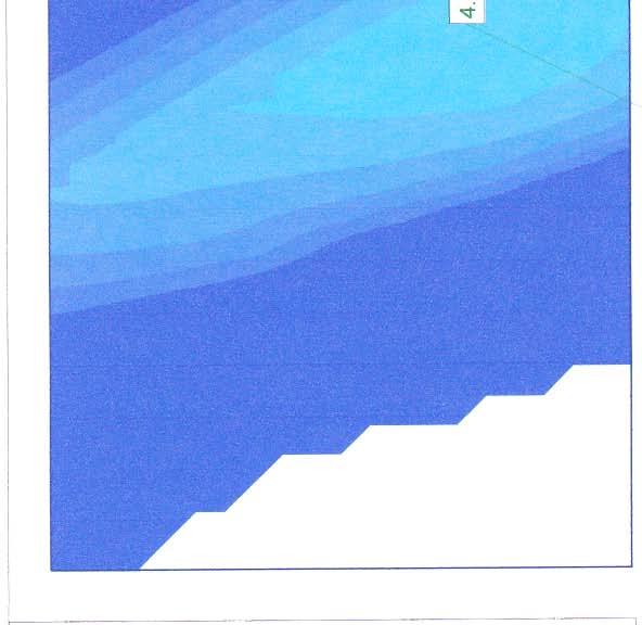
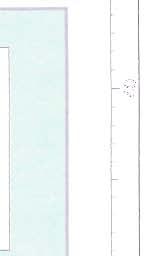
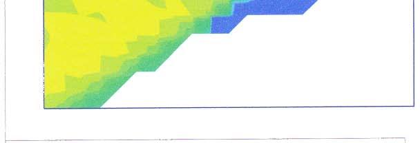
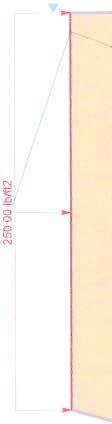
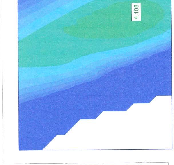
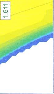
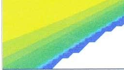
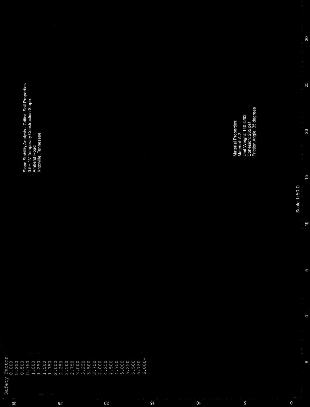
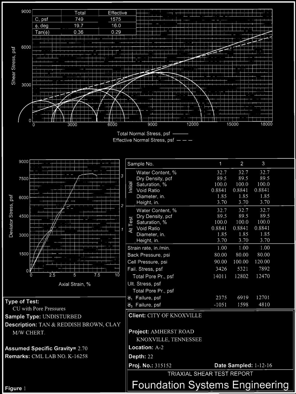
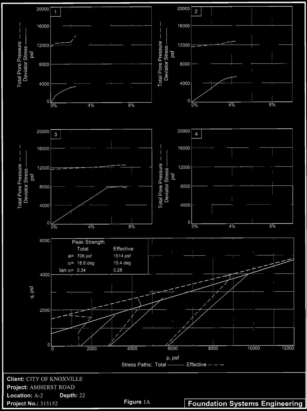
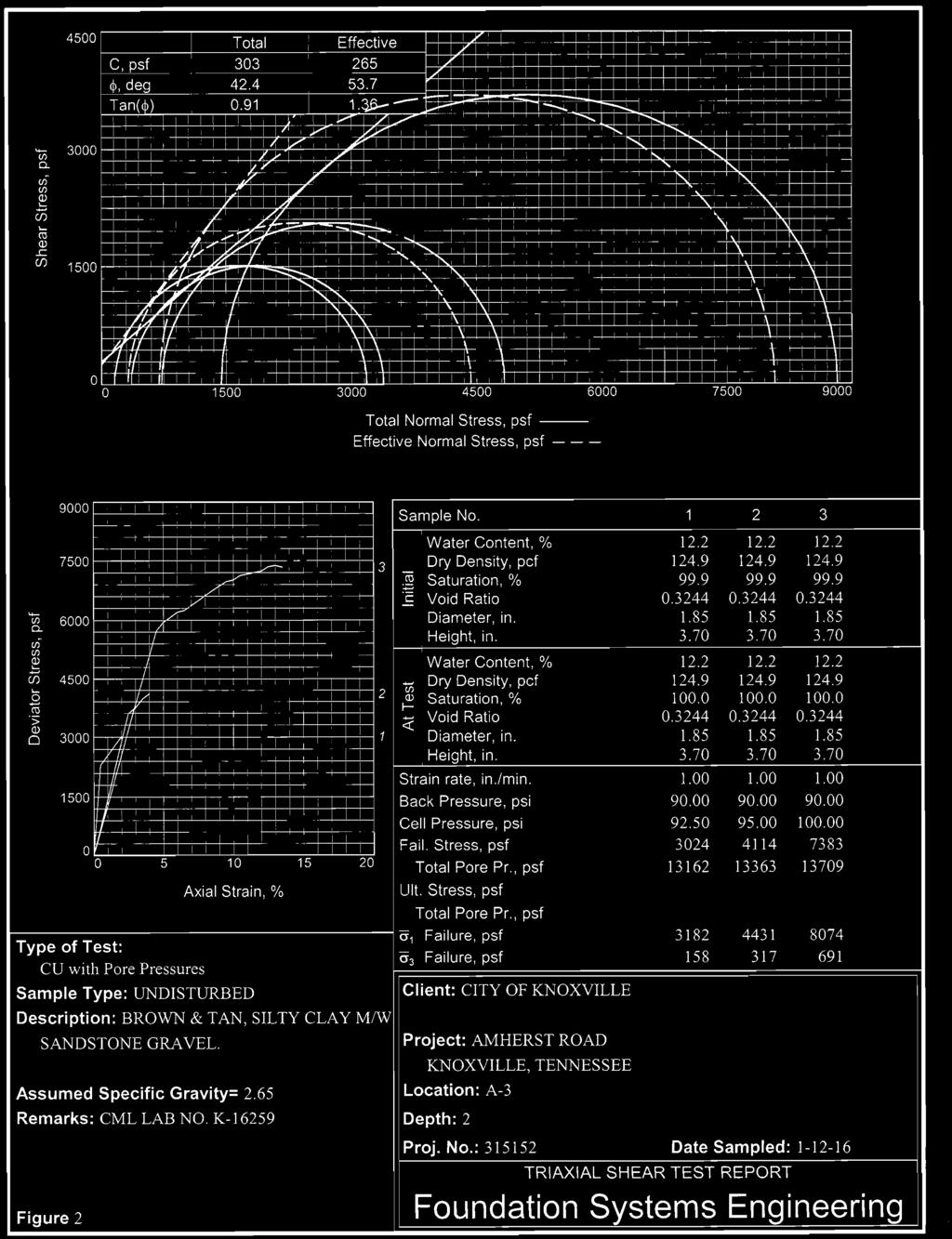
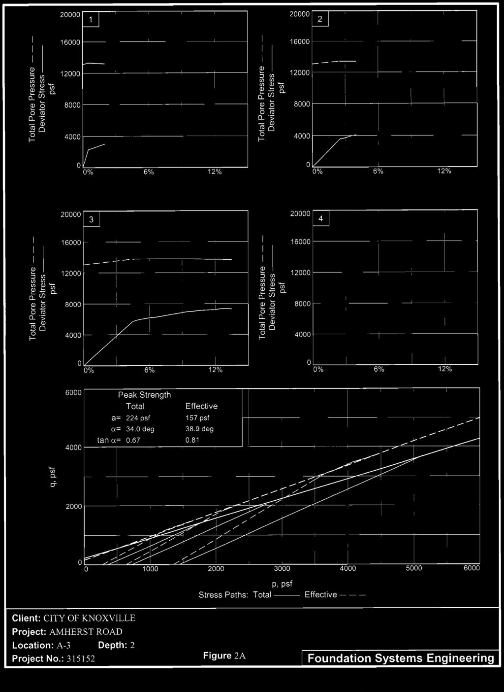
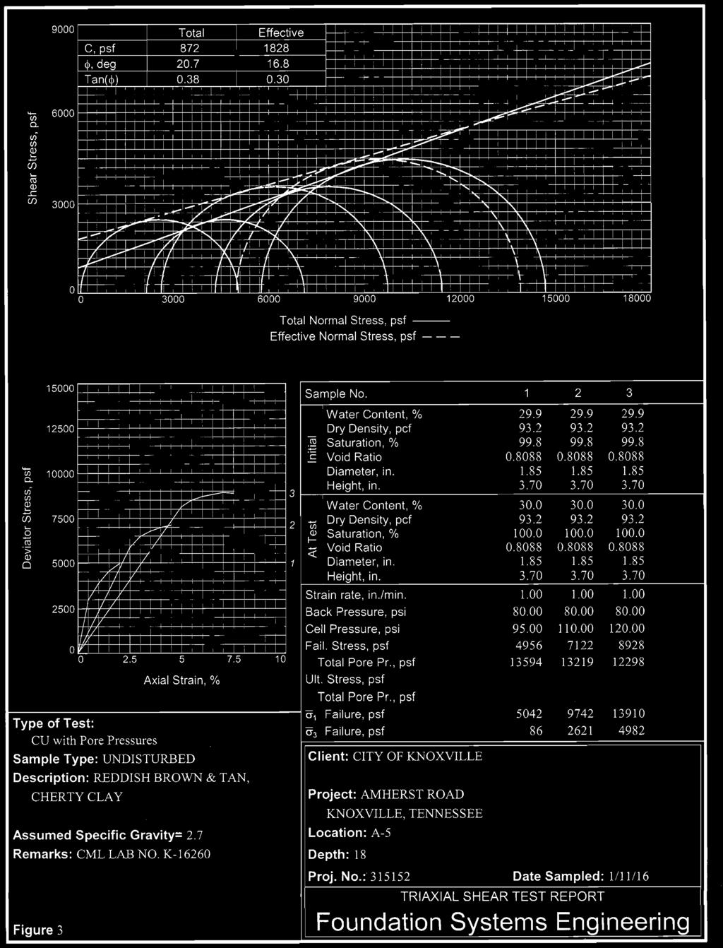
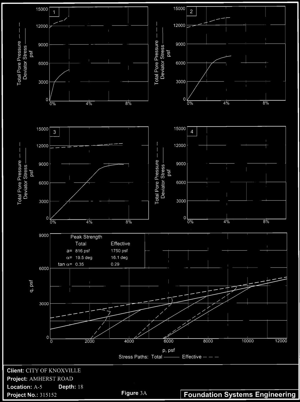
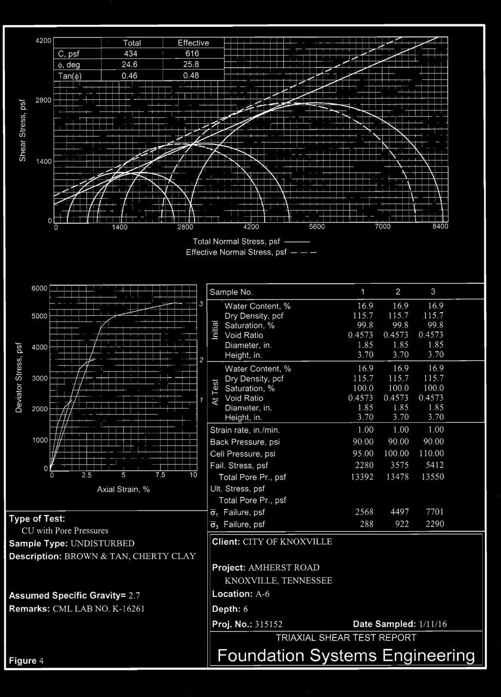
21 Mr. Shawn Fitzpatrick, P.E. May 10, 2016 Page Triaxial Shear Test Data Summary Five (5) samples of soil obtained from the Shelby tube sampling were selected for consolidated, undrained, effective stress triaxial shear testing. Samples were collected from each of the borings. The results of the triaxial shear testing may be seen in the following table. Boring Number Sample Depth, Ft. Table V Triaxial Shear Test Data Summary Wet Density, PCF Water Content - % Effective Cohesion PSF Effective Phi Angle Degrees Initial Void Ratio* A A A A A *Based on assumed specific gravity of The results of the triaxial shear testing were used for slope stability analysis for the slope located on the south side of Amherst Road, between the road and CSX rail line. The results of the slope stability analysis are discussed in the following section. 8.0 SLOPE STABILITY ANALYSIS Our stability analysis was completed using Slide (version 5.044) 2D Limit Equilibrium Slope Stability Analysis Software by Rocscience, Inc. Slide was developed to handle slope stability problems utilizing a number of methods. A circular search (global slope stability) using the Bishop Simplified and Spencer method of slices was utilized in the analysis of the slope. Three typical cross sections of the existing site was adapted from topographic data collected at the site by our firm. The existing slope geometry at each of the three cross sections along with estimated traffic loading was used in our analysis. Subsurface data utilized in our analysis is based on data obtained from site reconnaissance, soil auger borings, laboratory plasticity testing, and triaxial shear testing. The stability of slopes is discussed in terms of factor of safety values. Factor of safety values are the ratio of the soil driving force to the soil resisting force. The driving force consists of the weight of the soil or rock mass, plus any surcharge loading such as from
22 Mr. Shawn Fitzpatrick, P.E. May 10, 2016 Page 16 roadway traffic. The resisting force is the strength of the in-place soil or rock mass (soil friction angle and cohesion). Based on our past experience and data from published engineering texts, we offer the following general guidelines for evaluation of slope stability factor of safety values. At a factor of safety of less than 1, a slope failure can be expected. At a factor of safety of between 1 and 1.1, slope failures are common. At a factor of safety of between 1.1 and 1.25, slope failures do occur. At a factor of safety of greater than 1.25, slope failures almost never occur. The greater the factor of safety value, the less likely that a failure will occur. In their text entitled Soil Mechanics, T. W. Lambe and R. V. Whitman provide the following guidelines For intact homogenous soils, when the strength parameters have been chosen on the basis of good laboratory tests and a careful estimate of pore pressure has been made, a safety factor of at least 1.5 is commonly employed. With fissured clays and for non-homogenous soils larger uncertainties will generally exist and more caution is necessary. The on-site, in-place soils are non-homogenous. Data representing the inplace soil and rock is believed to be generally representative of the in-place soil. Based on the guidelines as outlined above, we recommend that a Factor of Safety of >1.5 be established as the minimum allowable slope stability. This recommendation also considers that the slope provides support to a roadway, and slope failure could encroach onto CSX rail lines. The results of our stability analysis of the existing slope are summarized in the following table. Illustrations of our analysis are included with this report. Table VI Slope Stability Analysis Summary Boring Location Factor of Safety (FS) A A A A A Based on the results of the testing performed, in our professional opinion the results of the testing performed indicate that the existing slope is stable with respect to mass instability. A global slope failure is not predicted to occur.
23 Mr. Shawn Fitzpatrick, P.E. May 10, 2016 Page 17 As described above, we did observe raveling and sluffing of the slope surface. There are sections where the shoulder and edge of the paved portion of the road have been lost. As such, while the slope is stable with regard to mass movement, loss of the roadway due to erosion and sluffing of the exposed outer surface material is occurring. As per our discussion with you, we understand that it is desirable to re-establish a portion of the roadway shoulder and the asphalt paved road. Also, it is desirable to construct a guard rail along the south shoulder, at the crest of the slope leading down to the railroad. In this regard we have considered several methods of slope retention to allow the shoulder reconstruction. Most methods would allow re-establishment of the roadway shoulder and construction of a guard rail system, and would add to the slope stability factor-of-safety value. However; given the existing good slope stability factor-of-safety values, in our opinion many of the considered systems would be costly without meaningful benefit. One system that was considered, and is recommended, is the use of Gabion Baskets placed at the crest of the slope to allow the roadway shoulder to be widened and a guard rail system to be constructed. The attached sketch graphically depicts our recommended stabilization technique. A slope stability analysis was performed using the Maccaferri Inc. GawacWin slope stability analysis program. The results of the analysis indicates an overall stability safety coefficient of With respect to sliding and overturning of the Gabion baskets, the results of the analysis indicates factors of safety of greater than The results of our analysis are included within the appendix of this report. A temporary construction slope with a slope geometry of 0.5H:1V and a maximum height of 10 feet was evaluated utilizing Slide. The temporary slope was modeled based on data obtained from soil auger borings, laboratory plasticity testing, and triaxial shear testing. The results of the temporary slope stability analysis indicate a factor of safety coefficient of The results of our analysis are included within the appendix of this report.
24 Mr. Shawn Fitzpatrick, P.E. May 10, 2016 Page RECOMMENDATIONS We offer the following geotechnical engineering recommendations for stabilization and reconstruction of the roadway shoulder, and placement of a guard rail system. Our recommendations are based on our site visit, review of available topographic and geologic mapping, field exploration, laboratory testing and engineering analysis. 9.1 Roadway Preparation We recommend that the roadway shoulder be widened and stabilized using Gabion baskets placed at the crest of the slope. A sketch that graphically depicts our recommended stabilization technique is included with this report. In preparation for the areas where the roadway shoulder needs to be re-established, we recommend that the southernmost (eastbound) traffic lane and proposed shoulder area be undercut down to firm, stable soil. The depth of undercut will be dependent on existing site topography, and the required depth to establish a 3-foot wide shoulder. We estimate undercut depths ranging from approximately 3 feet to approximately 6 feet below finished subgrade elevation in order achieve a suitable bearing area for the Gabion baskets. The existing asphalt pavement should be saw-cut prior to excavation. The temporary construction excavation behind the wall should be sloped no steeper than 0.5H to 1V, or otherwise braced. The temporary construction slope should be constructed no taller than 8 feet vertically. Traffic barriers should be placed along the crest of the excavation. Truck traffic and other heavy loads should not be allowed behind the temporary construction excavation. We recommend that truck traffic and other heavy traffic loads be diverted around the construction area. Once the lane and shoulder has been undercut to the necessary depth, the upper 6 inches of the in-place soil at the undercut level should be reworked and recompacted to a minimum of 95% Standard Proctor maximum dry density. Once reworked and recompacted the surface of the subgrade should be smoothed/leveled to remove clods, low areas, etc. Fine grading should be performed as necessary to ensure that the area has been adjusted to the proper elevation. ASTM C 33 size No. 57 crushed limestone gravel should be used as bedding and backfill material. The No. 57 sized stone should be compacted to the equivalent of a minimum of 95% Standard Proctor maximum dry density. Backfill lift thickness should be limited to a maximum of 12 inches, loose. In-place density testing should be performed concurrent with fill placement to ensure that the required compaction is achieved.
25 Mr. Shawn Fitzpatrick, P.E. May 10, 2016 Page 19 Once the surface has been smoothed, the bottom and sides of the excavation should be lined with a minimum 8-ounce per square yard weight non-woven geotextile. The geotextile should be placed hand-tight, such that wrinkles and grabs are removed. The geotextile should be lapped a minimum of 2 feet between roll widths and at the ends of the rolls. Once prepared as outlined above, the Gabion baskets should be constructed and filled. Gabion baskets are typically sized 3 feet wide; and range in height from 1 foot to 3 feet; and range in length from 4.5 feet to 12. The Gabion baskets should be constructed, filled, and set into place as per the Gabion basket manufacturer s specifications, and City of Knoxville technical specifications. The Gabion baskets should be filled with clean, crushed limestone cobbles (particle size range 5-12 ). The Gabion baskets should be set into place, with the baskets placed lengthwise back beneath the roadbed. A drain should be placed behind the baskets to ensure no ponding of water occurs. The drain system should consist of a perforated pipe, surrounded by No. 57 sized stone, with stone and pipe encased in a non-woven drainage geotextile. The drainage pipe should be sloped to ensure that positive drainage is maintained. All backfill material placed behind the Gabion baskets should consist of size No. 57 stone. 9.2 Pavement Repair Once the Gabion baskets have been constructed up to finished subgrade elevation as outlined above, we recommend that the roadway undercut/backfilled area be covered with a high modulus geotextile, such as Propex Geotex 315ST. The geotextile should be placed and secured in tension to ensure that wrinkles and grabs are removed. Successive sheets should be lapped a minimum of 2 feet. Once the geotextile has been placed and secured, the geotextile should be covered with 4 inches of ASTM C-33 No. 57 stone. The No. 57 stone should be compacted to the equivalent of a minimum of 95% Standard Proctor maximum dry density. With the roadway prepared as outlined above, we recommend that the roadway asphalt pavement section be replaced utilizing the following section thicknesses.
26 Mr. Shawn Fitzpatrick, P.E. May 10, 2016 Page 20 Table VII Asphalt Pavement Section Thickness Pavement Course Thickness, inches Tennessee Department of Transportation Amherst Road (TDOT) Specifications Asphalt Surface Course TDOT 411D 1.5 Asphalt Base Course TDOT 307BM 3.0 Aggregate Base TDOT 303D 8.0 The aggregate base should consist of a crushed limestone meeting the requirement of the Tennessee Department of Transportation (TDOT) specification for Mineral Aggregate Base, Section 303, for Type A base, Class A aggregates, utilizing aggregate gradation D. The aggregate base should be compacted to a minimum of 100% of its maximum dry density as determined by the Standard Proctor test, ASTM D698. The asphaltic base course should meet the specifications of TDOT, Section 307, Bituminous Plant Mix Base. The aggregates for the base course should meet the gradation requirements of Grading B Modified. The asphalt surface course should meet the specifications of TDOT 411, Asphaltic Concrete Surface, the aggregates for the mixture meeting the requirements of Grading D. The asphalt surface and base courses should be compacted to a minimum of 92% of their maximum theoretical density (MTD), ASTM D2041. The materials and placement method for the aggregate base and asphaltic surface and base courses should meet the specifications of the Tennessee Department of Transportation (TDOT) Road and Bridge Specifications. The new pavement should be sloped to taper/feather into the surrounding (existing) pavement such that the existing pavement slope and pavement drainage patterns are maintained. A slight crown in the pavement surface elevation over the center of the roadway is preferred; but, only if overall existing pavement drainage can be maintained. Under no circumstances should the repair area be left as a topographic low area, with water draining to and ponding in the repair area. The guardrail may be reinstalled and anchored into the Gabion shoulder utilizing a formed (sono-tube) concrete base.
27 Mr. Shawn Fitzpatrick, P.E. May 10, 2016 Page Erosion Control Measures The remaining slope located south (down gradient) of the Gabion baskets and roadway should be protected from erosion. We recommend that the slope be protected utilizing a turf reinforcement mat, such as Propex, Inc. Landlok TRM 1060 or engineer-approved equal. Installation of the turf reinforcement mat should be performed in accordance with the manufacture s specifications. Fine grading should be performed on the down gradient slope to ensure that the slope is no steeper than 1H:1V prior to placement of the mat. The seed selected for growth on the on the slope should meet CSX Railway and City of Knoxville requirements ESTIMATED COSTS Based on the results of the subsurface exploration, preliminary design work, and similar past projects, we offer the follow cost estimate breakdown for construction and quality control services in order to carry out the recommendations outlined within this report. This estimate does not include the costs of permits, flagmen, insurance, etc. that will be required by the CSX railway. Table VIII Engineers Estimate Service Estimated Cost Construction $325, Quality Control Services $32, Total $357, ADDITIONAL RECOMMENDED WORK Based on our familiarity with the site and the geotechnical considerations present, we believe that we are uniquely qualified to provide construction observation services during site grading and future building construction. We recommend that our firm be retained to provide quality control testing and observation services during construction.
28 Mr. Shawn Fitzpatrick, P.E. May 10, 2016 Page GENERAL QUALIFICATIONS This report has been prepared for the exclusive use of the City of Knoxville. This report has been prepared in accordance with generally accepted geotechnical engineering practice. Any conclusions and recommendations contained in this report are based upon applicable standards of our practice in this geographic area at the time this report was prepared. No other warranty, expressed or implied, is made. Foundation Systems Engineering, P.C is not responsible for any claims, damages, or liability associated with any other party s interpretation of this report s subsurface data or reuse of this report s subsurface data or engineering analysis without our express written authorization, nor for the conclusions, opinions, or recommendations made by others based on these data. The analyses and recommendations submitted herein are based, in part, upon the data obtained from our site visit and the subsurface exploration. The nature and extent of variations between the borings will not become evident until repair/stabilization. If variations appear evident, then it will be necessary to re-evaluate the opinions and recommendations contained in this report. In the event that any change in the nature, design, location, evaluation, etc. of the roadway shoulder failure occurs, the conclusions and recommendations contained in this report will not be considered valid unless the changes are reviewed and conclusions modified or verified in writing. If any subsurface variations become evident, a reevaluation of the opinions contained in this report will be necessary after we have had an opportunity to observe the characteristics of the conditions encountered. Any and all variations from the above outlined recommendations are considered as material changes/variations, and the recommendations and opinions contained in this report will not be considered valid unless these changes/variations are reviewed and conclusions modified or verified in writing. This report should not be made a part of project plans and specifications; but may be included with bidding documents for the convenience of the bidders.
29 APPENDICIES I. Typical Cross Section II. Slope Stability Analysis - Slide v. 5.0 III. Gabion Wall Analysis - GawacWin 2003 IV. Boring Location Plan & Auger Boring Records V. Laboratory Test Results a. Atterberg Limits b. Natural Moisture Content c. Triaxial Shear Test VI. ASFE
30 APPENDIX I Typical Cross Section
31 FOUNDATION SYSTEMS ENGINEERING, P.C. Geotechnical Engineering and Consulting TYPICAL CROSS SECTION AMHERST ROAD SHOULDER RESTORATION & STABILIZATION KNOXVILLE, TENNESSEE CITY OF KNOXVILLE 2203 ATCHLEY STREET P.O. BOX 9449 KNOXVILLE, TN FAX
32 APPENDIX II Slope Stability Analysis Slide v. 5.0


33


34


35


36


37


38
39 APPENDIX III Gabion Wall Anlaysis GawacWin 2003
40
41
42
43
44
45 APPENDIX IV Boring Location Plan & Auger Boring Records


46 FOUNDATION SYSTEMS ENGINEERING, P.C. Geotechnical Engineering and Consulting BORING LOCATION PLAN AMHERST ROAD SHOULDER RESTORATION & STABILIZATION KNOXVILLE, TENNESSEE CITY OF KNOXVILLE 2203 ATCHLEY STREET P.O. BOX 9449 KNOXVILLE, TN FAX
47
48
49
50
51
52
53
54
55
56
57
58
59 APPENDIX V Laboratory Test Results Atterberg Limits Natural Moisture Content Triaxial Shear Test
60
61
62
63
64
65
66
67
68
69
70
71
72 APPENDIX VI ASFE
73
74
May 2, Mr. Tim Kurmaskie, AIA ARCHITECT KURMASKIE ASSOCIATES, INC Washington Street Raleigh, NC
 Mr. Tim Kurmaskie, AIA ARCHITECT KURMASKIE ASSOCIATES, INC. 1030 Washington Street Raleigh, NC 27605-1258 May 2, 2017 Re: Report of Subsurface Investigation Westfield Rehabilitation & Health Care Additions
GEOTECHNICAL ENGINEERING REPORT
 GEOTECHNICAL ENGINEERING REPORT 58.6 ROAD (KIMBALL CREEK) 58.9 ROAD TO 58.7 ROAD MESA COUNTY, COLORADO February 9, 2018 Prepared By: Prepared For: Mr. Eric Krch, P.E. SGM, Inc. 744 Horizon Court, Suite
Geotechnical Investigation Long Timber Brewing Building Highway 99 and Kelly Street Monroe, Oregon TABLE OF CONTENTS
 Highway 99 and Kelly Street TABLE OF CONTENTS PROJECT INFORMATION... 1 FIELD EXPLORATION... 1 SITE CONDITIONS... 2 Surface Conditions:... 2 Subsurface Conditions:... 2 FILL.... 2 Topsoil.... 2 Clay Alluvium....
June i TABLE OF CONTENTS
 June 2005 - i - 05-526 TABLE OF CONTENTS SECTION PAGE 1.0 INTRODUCTION... 1 1.1 Purpose of the Investigation... 1 1.2 Description of the Project and Scope of Work... 1 1.3 Site Geology... 1 1.4 Site Description
GEOTECHNICAL INVESTIGATION PROPOSED OUTFALL LOCATION CITY OF MORGAN S POINT DRAINAGE HARRIS COUNTY, TEXAS REPORT NO
 GEOTECHNICAL INVESTIGATION PROPOSED OUTFALL LOCATION CITY OF MORGAN S POINT DRAINAGE HARRIS COUNTY, TEXAS REPORT NO. 1140198001 Reported to: SIRRUS ENGINEERS, INC. Houston, Texas Submitted by: GEOTEST
April 7, Webster Street Sub-Surface Stormwater Storage System Bid No Bid Date: 4/13/17 ADDENDUM NO 1
 PUBLIC WORKS DEPARTMENT David A. Jones, P.E., Director April 7, 2017 Webster Street Sub-Surface Stormwater Storage System Bid No. 2017-022 Bid Date: 4/13/17 ADDENDUM NO 1 Please make the following changes
Subsurface Investigation Report. Proposed New 1-Story Building 6447 Grand Avenue Gurnee, Illinois
 AGI Project No. -11 Subsurface Investigation Report For the Proposed New 1-Story Building 6447 Grand Avenue Gurnee, Illinois Prepared for Mr. Steve Panko Key Development Partners, LLC North State Street,
Ohio Department of Transportation Division of Production Management Office of Geotechnical Engineering. Geotechnical Bulletin
 Ohio Department of Transportation Division of Production Management Office of Geotechnical Engineering Geotechnical Bulletin GB 2 SPECIAL BENCHING AND SIDEHILL EMBANKMENT FILLS Geotechnical Bulletin GB2
EEI PROJECT NUMBER 5891G-NC PREPARED FOR: HILCO LTD 1435 US HIGHWAY 285 N KINSTON, NC SUBMITTED BY: MATTHEW C. KIRCHNER, E.I.
 SUMMARY REPORT OF GEOTECHNICAL SUBSURFACE EXPLORATION AND ENGINEERING EVALUATION PROPOSED PINEY GROVE NURSING & REHABILIATION CENTER EXPANSION 728 PINEY GROVE RD KERNERSVILLE, NORTH CAROLINA EEI PROJECT
mtec REPORT OF GEOTECHNICAL EXPLORATION FTFA Construct Bin Wall at HERD Eglin AFB, Florida
 mtec REPORT OF GEOTECHNICAL EXPLORATION FTFA 14-3001 - Construct Bin Wall at HERD Eglin AFB, Florida MTEC Project Number 2014-101 November 10, 2014 Revised: January 5, 2015 Prepared For: Peterson Engineering,
DEPARTMENT OF TRANSPORTATION DIVISION: MATERIALS REPORT COVER SHEET. Revised Soil Survey Report November 24, 2015 Matthew G. Moore, P.E.
 LD-0 /12/09 DEPARTMENT OF TRANSPORTATION DIVISION: MATERIALS REPORT COVER SHEET Revised Soil Survey Report November 2, 201 Matthew G. Moore, P.E. VDOT (Division) or Company Name Insert Location, Virginia
Applied GeoScience, Inc Hammond Dr., Suite 6 Schaumburg, Illinois
 AGI Project No. 13-276 Subsurface Investigation Report For the Proposed New Retail Center 9601 South Pulaski Road Evergreen Park, Illinois Prepared for Mr. Feras Sweis FHS Design + Build LLC 2010 West
Civil Geotechnical Surveying
 Civil Geotechnical Surveying Mr. David Burnett Cabarrus County Schools 4425 Old Airport Road Charlotte, North Carolina 28025 May 16, 2017 Reference: Geotechnical Engineering Evaluation Future PLC Site
Geotechnical Exploration and Evaluation Report
 Geotechnical Exploration and Evaluation Report Nassau Reclaimed Water Main From Radio Avenue to Harts Road Nassau County, Florida CSI Geo Project No.: 71-17-329-04 Client Project No.: JEA 09302-049-01
Geotechnical Engineering Report Proposed Communications Tower Spain Park Site Hoover, Alabama
 Geotechnical Engineering Report Proposed Communications Tower Spain Park Site Hoover, Alabama July 24, 2014 Terracon Project No. E1145095 Prepared for: The City Of Hoover Hoover, Alabama Prepared by: Terracon
GEOTECHNICAL STUDY PROPOSED CONCRETE ROADWAY TIKI ISLAND COMMUNITY GALVESTON COUNTY, TEXAS PROJECT NO E
 GEOTECHNICAL STUDY PROPOSED CONCRETE ROADWAY TIKI ISLAND COMMUNITY GALVESTON COUNTY, TEXAS PROJECT NO. 15-945E TO VILLAGE OF TIKI ISLAND TIKI ISLAND, TEXAS BY SERVICING TEXAS, LOUISIANA, NEW MEXICO, OKLAHOMA
SUBSURFACE INVESTIGATION & GEOTECHNICAL RECOMMENDATIONS PROPOSED MONOPOLE CELL TOWER INDIANAPOLIS, INDIANA A&W PROJECT NO: 15IN0464
 SUBSURFACE INVESTIGATION & GEOTECHNICAL RECOMMENDATIONS PROPOSED MONOPOLE CELL TOWER INDIANAPOLIS, INDIANA A&W PROJECT NO: 15IN0464 PREPARED FOR: AAA DEVELOPMENT AND CONSULTING, INC GREENFIELD, INDIANA
GEOTECHNICAL ENGINEERING REPORT. KU Parking Lot 300E Southeast of Lied Center Lawrence, Kansas. Project No. D16G1696. KU No. Lz_n/11062.
 GEOTECHNICAL ENGINEERING REPORT KU Parking Lot 300E Southeast of Lied Center Lawrence, Kansas April 1, 2016 Prepared for: University of Kansas Bartlett & West Prepared by: GeoSource, LLC April 1, 2016
MEMORANDUM. TO: STUART OLSON DOMINION CONSTRUCTION LTD. DATE: JANUARY 31, 14 ATTENTION: MR. Dave Bauder, Construction Manager KENNY K. C.KO, P.ENG.
 MEMORANDUM Levelton Consultants Ltd. 150-12791 Clarke Place Richmond, BC V6V 2H9 Canada Tel: 604 278-1411 Fax: 604 278-1042 E-Mail: rhillaby@levelton.com Web Site: www.levelton.com TO: STUART OLSON DOMINION
PRELIMINARY GEOTECHNICAL INVESTIGATION UCCS ACADEMIC OFFICE BUILDING COLORADO SPRINGS, COLORADO
 PRELIMINARY GEOTECHNICAL INVESTIGATION UCCS COLORADO SPRINGS COLORADO Prepared for: UNIVERSITY OF COLORADO AT COLORADO SPRINGS Facilities Services 1420 Austin Bluffs Parkway Colorado Springs Colorado 80918
Report of CCR Rule Stability Analyses AEP Clifty Creek Power Plant Boiler Slag Pond Dam and Landfill Runoff Collection Pond
 Report of CCR Rule Stability Analyses AEP Clifty Creek Power Plant Boiler Slag Pond Dam and Landfill Runoff Collection Pond Madison, Jefferson County, Indiana Prepared for: American Electric Power Columbus,
REPORT OF GEOTECHNICAL CONSULTING SERVICES
 REPORT OF GEOTECHNICAL CONSULTING SERVICES Escambia County Public Works Department Thompson, Crary and McNeal Roadway Project Escambia County, Century,FL Thompson Engineering Project No.: 15-1101-0297
Geotechnical Investigation Report
 Geotechnical Investigation Report Proposed,000-Gallon Water Storage Tank Fagasa Pass Tank Upper Pago Pago, American Samoa Prepared for: ASPA Water Engineering Division Tafuna, American Samoa PO Box PPB
SPECIFICATIONS FOR PRECAST MODULAR BLOCK RETAINING WALL SYSTEM (revised 5/8/7)
") Page 1 of 7 STONE STRONG SYSTEMS SPECIFICATIONS FOR PRECAST MODULAR BLOCK RETAINING WALL SYSTEM (revised 5/8/7) PART 1: GENERAL 1.01 Description A. Work includes furnishing and installing precast modular
Page 1 of 7 STONE STRONG SYSTEMS SPECIFICATIONS FOR PRECAST MODULAR BLOCK RETAINING WALL SYSTEM (revised 5/8/7) PART 1: GENERAL 1.01 Description A. Work includes furnishing and installing precast modular
Lantz-Boggio Architects, P.C LBA Project No
 SECTION 313430- PART 1 GENERAL 1.1 WORK INCLUDED A. Provide all equipment, material, labor and supervision to design and install Engineered Aggregate Piers for the soil reinforcement. Design shall rely
Geotechnical Exploration and Evaluation Report
 Geotechnical Exploration and Evaluation Report Pavement Coring and Evaluation UNF Parking Lot 3 Jacksonville, Florida CSI Geo Project No.: 71-18-135-23 Prepared by CSI Geo, Inc. 2394 St. Johns Bluff Road
ORLANDO SANFORD INTERNATIONAL AIRPORT OUTPARCEL 6 SANFORD, FLORIDA
 PRELIMINARY GEOTECHNICAL STUDY ORLANDO SANFORD INTERNATIONAL AIRPORT OUTPARCEL 6 SANFORD, FLORIDA November 9, 2015 Prepared For: Ms. Diane H. Crews, A.A.E. Sanford Airport Authority 1200 Red Cleveland
REPORT OF GEOTECHNICAL EXPLORATION WEST MARJORY AVENUE TAMPA, FLORIDA
 REPORT OF GEOTECHNICAL EXPLORATION WEST MARJORY AVENUE TAMPA, FLORIDA AREHNA PROJECT NO. B-15-008 March 11, 2015 Prepared For: City of Tampa Stormwater Division 306 W. Jackson Street, 6N Tampa, Florida
SECTION TRENCHING, BACKFILLING AND COMPACTION. B. Provide necessary sheeting, shoring and bracing.
 SECTION 02221 TRENCHING, BACKFILLING AND COMPACTION PART 1 GENERAL 1.01 WORK INCLUDED A. Excavation for piped utility material. B. Provide necessary sheeting, shoring and bracing. C. Prepare trench bottom
PROJECT INFORMATION... 1 SITE AND SUBSURFACE CONDITIONS... 2 EVALUATION AND RECOMMENDATIONS... 4 CONSTRUCTION CONSIDERATIONS... 5
 TABLE OF CONTENTS Page No. PROJECT INFORMATION... 1 Project Authorization... 1 Project Description... 1 Purpose and Scope of Services... 1 SITE AND SUBSURFACE CONDITIONS... 2 Site Location and Description...
T. Brian Williamson, P.E. Matthew B. Haston, P.E.
 September 22, 2017 Realty Link, LLC 550 South Main Street Greenville, South Carolina 29601 ATTENTION: Subject: Mr. Chris Swale cswale@realtylinkdev.com REPORT OF GEOTECHNICAL EXPLORATION Oak Ridge Main
March 10, 2017 SITE AND PROJECT INFORMATION
 March 10, 2017 Derek Hawkes, PE NASH COUNTY 120 W. Washington Street - Suite 2004 Nashville, NC 27856 Re: Report of Subsurface Investigation Middlesex Corporate Park, Lot 3 Middlesex, North Carolina GeoTechnologies
SECTION / ENGINEERED AGGREGATE PIERS (SOIL REINFORCEMENT AND FOUNDATION SYSTEM)
") PART 1 GENERAL 1.01 WORK INCLUDED SECTION 02360 / 31 34 30.13 ENGINEERED AGGREGATE PIERS (SOIL REINFORCEMENT AND FOUNDATION SYSTEM) A. Provide all equipment, material, labor and supervision to design and
PART 1 GENERAL 1.01 WORK INCLUDED SECTION 02360 / 31 34 30.13 ENGINEERED AGGREGATE PIERS (SOIL REINFORCEMENT AND FOUNDATION SYSTEM) A. Provide all equipment, material, labor and supervision to design and
REPORT OF GEOTECHNICAL EXPLORATION AND ENGINEERING ANALYSIS
 FIGURE 3 Geotechnical Report (2) REPORT OF GEOTECHNICAL EXPLORATION AND ENGINEERING ANALYSIS RIVER TOWER RESTORATION RIVER TOWER PARK TAMPA, FLORIDA AREHNA PROJECT NO. B-13-002 February 22, 2013 Prepared
1.0 PROJECT INFORMATION. 1.1 Site Location and Description. October 31, 2017
 October 31, 2017 City of Oelwein c/o Fox Engineering 414 South 17 th Street, Suite 107 Ames, IA 50010 Attn: Re: Ms. Jessica M.B. Fisher, P.E. Project Manager P: (515) 233-0000 E: jmf@foxeng.com Proposal
SPECIFICATIONS FOR PRECAST MODULAR BLOCK RETAINING WALL SYSTEM (revised 9/17/18)
") Page 1 of 8 STONE STRONG SYSTEMS SPECIFICATIONS FOR PRECAST MODULAR BLOCK RETAINING WALL SYSTEM (revised ) PART 1: GENERAL 1.01 Description A. Work includes furnishing and installing precast modular blocks
Page 1 of 8 STONE STRONG SYSTEMS SPECIFICATIONS FOR PRECAST MODULAR BLOCK RETAINING WALL SYSTEM (revised ) PART 1: GENERAL 1.01 Description A. Work includes furnishing and installing precast modular blocks
SECTION SOILS REPORT
 SECTION 02300 SOILS REPORT 1. GENERAL: 1.1 All work included under this heading shall be subject to the General Conditions of the entire operation. This Contractor is required to refer especially thereto.
ADDENDUM NO. 1. PROJECT NAME: Bostic Pelt Road NRCS Drainage Improvements PRI PROJECT NO: Wakulla Co ITB#
 ADDENDUM NO. 1 DATE: January 22, 214 TO: Prospective Bidders via individual e-mails FROM: Alan Wise, P.E. PROJECT NAME: Bostic Pelt Road NRCS Drainage Improvements PRI PROJECT NO: 23.15 ---- Wakulla Co
Reinforced Soil Slopes (RSS)
") Supplemental Technical Specification for Reinforced Soil Slopes (RSS) SCDOT Designation: SC-M-206-1 (4/16) 1.0 DESCRIPTION 1.1 Construct a reinforced soil slope in accordance with these specifications,
Supplemental Technical Specification for Reinforced Soil Slopes (RSS) SCDOT Designation: SC-M-206-1 (4/16) 1.0 DESCRIPTION 1.1 Construct a reinforced soil slope in accordance with these specifications,
GEOTECHNICAL ENGINEERING REPORT
 GEOTECHNICAL ENGINEERING REPORT PROJECT MINECRAFT ACCESS ROAD BOYDTON PLANK ROAD DINWIDDIE COUNTY, VIRGINIA JOB NUMBER: 37775.003 PREPARED FOR: DINWIDDIE COUNTY PO BOX 70 DINWIDDIE COUNTY, STATE 23841
ORLANDO SANFORD INTERNATIONAL AIRPORT OUTPARCEL 1 SANFORD, FLORIDA
 PRELIMINARY GEOTECHNICAL STUDY ORLANDO SANFORD INTERNATIONAL AIRPORT OUTPARCEL 1 SANFORD, FLORIDA November 9, 2015 Prepared For: Ms. Diane H. Crews, A.A.E. Sanford Airport Authority 1200 Red Cleveland
CHAPTER 11: WALLS.
 CHAPTER 11: WALLS MODULAR BLOCK WALL (DRY CAST) Rather than being pre-approved as systems, the components of Modular block walls (dry cast) are pre-approved separately. The approved MBW components are
GEOTECHNICAL EXPLORATION FOR PROPOSED PAVEMENT IMPROVEMENTS, SIERRA MIDDLE SCHOOL, 4950 CENTRAL AVENUE, CITY OF RIVERSIDE, CALIFORNIA.
 GEOTECHNICAL EXPLORATION FOR PROPOSED PAVEMENT IMPROVEMENTS, SIERRA MIDDLE SCHOOL, 4950 CENTRAL AVENUE, CITY OF RIVERSIDE, CALIFORNIA Prepared for: RIVERSIDE UNIFIED SCHOOL DISTRICT 3070 Washington Street
DEPARTMENT OF TRANSPORTATION DIVISION: MATERIALS REPORT COVER SHEET. Soil Survey Report March 29, 2015 Matthew G. Moore, P.E.
 LD-40 /12/09 DEPARTMENT OF TRANSPORTATION DIVISION: MATERIALS REPORT COVER SHEET Soil Survey Report March 29, 201 Matthew G. Moore, P.E. VDOT (Division) or Company Name Insert Location, Virginia Insert
Ardaman & Associates, Inc. Geotechnical, Environmental and Materials Consultants
 SUBSURFACE SOIL EXPLORATION ANALYSIS AND RECOMMENDATIONS PROPOSED WEIRS AT STATIONS 130+00 AND 16+00 DRAINAGE IMPROVEMENTS TO THE FOUR CORNERS MSBU HENDRY COUNTY, FLORIDA Ardaman & Associates, Inc. Geotechnical,
SECTION TRENCHING
 SECTION 31 23 17 TRENCHING PART 1 GENERAL 1.1 SUMMARY A. Section Includes: 1. Excavating trenches for utilities and utility structures. 2. Bedding. 3. Backfilling and compacting to subgrade elevations.
B. Borrow: Satisfactory soil imported from off-site for use as fill or backfill.
 SECTION 312000- EARTHWORK PART 1 - GENERAL 1.1 RELATED DOCUMENTS Drawings and general provisions of the Contract, including General and Special Conditions, apply to this Section. 1.2 SUMMARY This Section
Results of Onsite Percolation Testing Ellis Commons Senior Housing Development APN City of Perris, California
 Lansing Companies 12671 High Bluff Drive, Suite 150 San Diego, California 92130 April 18, 2017 Project No. 11607.001 Attention: Subject: References: Mr. Casey Malone Results of Onsite Percolation Testing
PROJECT INFORMATION EVALUATION PROCEDURES
 April 10, 2012 Board of Directors Hunters Ridge Amenities Association, Inc. 422 Hunters Circle Greenville, SC 29617 Attention: Mr. Jerry Miller Mr. Bruce Williams Re: Engineering Evaluation of Existing
Geotechnical Engineering Report
 Geotechnical Engineering Report Caswell County Public Library Yanceyville, North Carolina June 15, 2017 Project No. 75175054 Revised Prepared for: Gunn Memorial Public Library Yanceyville, North Carolina
GEOTECHNICAL INVESTIGATION ADDENDUM Pavement Improvements for Imperial Avenue, Wake Avenue, and Danenberg Drive, El Centro, California
 Mr. Victor Garcia The Holt Group 1601 N. Imperial Ave. El Centro, California 92243 September 28, 2017 Project No. EC595 SUBJECT: REFERENCE: GEOTECHNICAL INVESTIGATION ADDENDUM Pavement Improvements for
REPORT OF LIMITED SUBSURFACE AND EXISTING PAVEMENT EVALUATION Melrose Street Reconstruction Winston-Salem, North Carolina S&ME Project No.
 REPORT OF LIMITED SUBSURFACE AND EXISTING PAVEMENT EVALUATION Melrose Street Reconstruction Winston-Salem, North Carolina S&ME Project No. 1583-12-129 Prepared for: City of Winston-Salem Engineering 100
 FIGURES Printed By: aday Print Date: 3/23/2011 12:48:08 PM File Name: \\geodesign.local\files\jobs\m-r\penskeauto\penskeauto-1\penskeauto-1-01\figures\cad\penskeauto-1-01-vm01.dwg Layout: FIGURE 1 VICINITY
April 6, TN Oak Ridge Rutgers, LLC 550 South Main Street, Suite 300 Greenville, South Carolina 29601
 April 6, 2018 TN Oak Ridge Rutgers, LLC 550 South Main Street, Suite 300 Greenville, South Carolina 29601 ATTENTION: Subject: Ms. Maude Davis, Director of Legal mdavis@realtylinkdecv.com REPORT OF GEOTECHNICAL
Section 1: Geotechnical Report Manual
 Version 1.0 Tennessee Department of Transportation Geotechnical Engineering Section Geo Manual Section 1 Issued: 3/15/07 Section 1: Geotechnical Report Manual 6601 Centennial Boulevard Nashville, TN 37243-0360
Typical Subsurface Profile. November 28, 2016
 November 28, 2016 RSCCD Facility Planning, District Construction and Support Services 2323 N. Broadway, Suite 112, Santa Ana, CA 92706 Attn: Re: Ms. Allison Coburn Facilities Project Manager P: (714) 480-7530
Required liner. thickness depends on acceptable seepage rate, soil permeability characteristics, and manure depth according to Darcy s Law.
 Soils Considerations for Earthen Impoundments Many natural soils will tend to partly seal due to manure solids plugging pore spaces between soil particles. Chemicals (salts) in manure tend to disperse
SECTION 10 - TRENCHING AND BACKFILLING
 SECTION 10 - TRENCHING AND BACKFILLING 10.1 General A. Work included in this Section includes trenching and backfilling for underground pipelines and related structures only. 10.1.1 Related requirements
6980 Sierra Center Parkway, Suite 90 Reno, NV 89511
 6980 Sierra Center Parkway, Suite 90 Reno, NV 89511 January 8, 2018 Project No: 2004 Mr. Tracy Carter SOMERSETT OWNERS ASSOCIATION 7650 Town Square Way Reno, NV 89523 RE: Rockery Wall Preliminary Failure
COMPACTED CLAY LINERS
 Technical Reference Document for Liquid Manure Storage Structures COMPACTED CLAY LINERS Table of Contents SECTION 1 - PURPOSE AND SCOPE 1.1. Purpose of the Technical Reference Document 1.2. Requirement
EXHIBIT G GEOTECHNICAL REPORT (DRAFT)
") EXHIBIT G GEOTECHNICAL REPORT (DRAFT) APPENDIX 1 PROJECT SITE 'B' B-1 B-2 I-2 B-3 B-4 B-5 I-1 PROJECT LOCATION LEGEND B-1 = APPROXIMATE BORING LOCATION I-1 = APPROXIMATE INFILTRATION
EXHIBIT G GEOTECHNICAL REPORT (DRAFT) APPENDIX 1 PROJECT SITE 'B' B-1 B-2 I-2 B-3 B-4 B-5 I-1 PROJECT LOCATION LEGEND B-1 = APPROXIMATE BORING LOCATION I-1 = APPROXIMATE INFILTRATION
SECTION 14 - RESTORATION OF SURFACES TABLE OF CONTENTS
 SECTION 14 - RESTORATION OF SURFACES TABLE OF CONTENTS Section Page 14-1 GENERAL... 14.1 14-2 PRIVATE ROADS... 14.1 14-3 STREETS AND PARKING LOTS... 14.1 14-3.01 Aggregate Base... 14.1 14-3.02 Asphalt
SECTION 14 - RESTORATION OF SURFACES TABLE OF CONTENTS
 SECTION 14 - RESTORATION OF SURFACES TABLE OF CONTENTS Section Page SECTION 14 RESTORATION OF SURFACES... 14.1 14-1 GENERAL... 14.1 14-2 PRIVATE ROADS... 14.1 14-3 STREETS AND PARKING LOTS... 14.1 14-3.01
MagnumStone Specifications Gravity
 MagnumStone Specifications Gravity SPECIFICATION FOR MAGNUMSTONE GRAVITY MECHANICALLY STABILIZED EARTH SYSTEM PART 1: GENERAL.01Description The work consists of supplying and installing all aspects of
APPENDIX F GEOTECHNICAL INVESTIGATION UPDATE CITY OF SANTA CRUZ D RAFT EIR L A B AHIA H OTEL JANUARY 2014
 GEOTECHNICAL INVESTIGATION UPDATE. CITY OF SANTA CRUZ D RAFT EIR L A B AHIA H OTEL JANUARY 2014 October 5, 2013 Project No. SCR-0720 SANTA CRUZ SEASIDE COMPANY Craig French 911 Center Street, Suite B Santa
B. Base Course: Aggregate layer placed between the subbase course and hot-mix asphalt paving.
 SECTION 312000 - EARTH MOVING PART 1 - GENERAL 1.1 SUMMARY A. Section Includes: 1. Excavating and filling for rough grading the Site. 2. Preparing subgrades for walks, curbs, pavements, and turf and grasses.
DIVISION 2100 SITEWORK
 DIVISION 2100 SITEWORK SECTION 2120 STABILIZED SUBGRADE PART 1 - GENERAL 1.01 SCOPE This section covers the preparation of subgrade for pavement, sidewalks, recreational trails, and drive approaches. 1.02
Geotechnical Engineering Study Report
 Geotechnical Engineering Study Report The report has been prepared for use in developing an overall design concept. Paragraphs, statements, test results, boring logs, diagrams, etc., should not be taken
REVISED REPORT OF GEOTECHNICAL EXPLORATION. Proposed Dollar Tree East 17 th Street and Old Greenbrier Road Springfield, Tennessee.
 REVISED REPORT OF GEOTECHNICAL EXPLORATION Proposed Dollar Tree East 17 th Street and Old Greenbrier Road Springfield, Tennessee Prepared for: Mr. K. Scott Brown Clark, Geer, Latham & Associates, Inc.
Table of Contents 5.1 GENERAL Overview Investigation and Engineering Information
 Table of Contents Section Page 5.1 GENERAL... 5.1-1 5.1.1 Overview... 5.1-1 5.1.2 Investigation and Engineering Information... 5.1-2 5.2 PRELIMINARY GEOTECHNCIAL REPORTS... 5.2-1 5.2.1 Preliminary Geotechnical
204 - EXCAVATION AND BACKFILL FOR STRUCTURES SECTION 204 EXCAVATION AND BACKFILL FOR STRUCTURES. Granular Backfill (Wingwalls) (Set Price)
 (Set Price)") SECTION 204 EXCAVATION AND BACKFILL FOR STRUCTURES 204.1 DESCRIPTION Excavate for the structures as shown in the Contract Documents. Unless specified otherwise, backfill the completed structures to the
SECTION 204 EXCAVATION AND BACKFILL FOR STRUCTURES 204.1 DESCRIPTION Excavate for the structures as shown in the Contract Documents. Unless specified otherwise, backfill the completed structures to the
SECTION 19 - TRENCH EXCAVATION, BEDDING AND BACKFILL TABLE OF CONTENTS
 SECTION 19 - TRENCH EXCAVATION, BEDDING AND BACKFILL TABLE OF CONTENTS Section Page 19-1 TRENCH EXCAVATION... 19.1 19-1.01 Exploratory Excavation... 19.1 19-1.02 Trench Width... 19.1 19-1.02.A Storm Drain
August 15, 2006 (Revised) July 3, 2006 Project No A
 July 3, 2006 Project No A") August 15, 2006 (Revised) July 3, 2006 Project No. 01-05-0854-101A Mr. David Reed, P.E. Protean Design Group 100 East Pine Street, Suite 306 Orlando, Florida 32801 Preliminary Soil Survey Report Polk Parkway
August 15, 2006 (Revised) July 3, 2006 Project No. 01-05-0854-101A Mr. David Reed, P.E. Protean Design Group 100 East Pine Street, Suite 306 Orlando, Florida 32801 Preliminary Soil Survey Report Polk Parkway
SECTION XXXXX AGGREGATE PIERS PART 1 - GENERAL
 SECTION XXXXX AGGREGATE PIERS PART 1 - GENERAL 1.1 RELATED DOCUMENTS: Drawings and general provisions of the Contract, including General and Supplementary Conditions and other Division 00 and Division
PRELIMINARY GEOTECHNICAL INVESTIGATION UCCS PARKING GARAGE STANTON STREET AND AUSTIN BLUFFS PARKWAY COLORADO SPRINGS, COLORADO
 PRELIMINARY GEOTECHNICAL INVESTIGATION UCCS PARKING GARAGE STANTON STREET AND AUSTIN BLUFFS PARKWAY COLORADO SPRINGS, COLORADO Prepared for: UNIVERSITY OF COLORADO AT COLORADO SPRINGS Facilities Services
DIVISION 4100 SITEWORK
 DIVISION 4100 SITEWORK SECTION 4115 EARTHWORK PART 1 - GENERAL 1.01 SCOPE This section covers the grading and compaction of excavations, embankments, structural foundations, and planted areas. 1.02 REFERENCES
Geotechnical Investigation
 Geotechnical Investigation Prepared for: Precision Approach Engineering, Inc. Corvallis, Oregon January 16, 2017 Professional Geotechnical Services Foundation Engineering, Inc. GEOTECHNICAL INVESTIGATION
Geotechnical Engineering Study
 Geotechnical Engineering Study SAWS Service Road Brackish Desalinization Production Well Services Package I Bexar County, Texas Arias Job No. 09-1122 Prepared For LBG Guyton & Associates March 9, 11 TABLE
PREPARED FOR: NORTH WEBSTER PARISH INDUSTRIAL DISTRICT SPRINGHILL, LOUISIANA
 PRELIMINARY REPORT OF SUBSURFACE EXPLORATION AND GEOTECHNICAL EVALUATION 64 ACRES, 5 SECTIONS NWPID CULLEN, LOUISIANA DAVE RAMBARAN GEOSCIENCES, LLC PROJECT NUMBER: 3021 DATE: MARCH 31, 2013 PREPARED FOR:
KU Design Guidelines APPENDIX II PERMEABLE BITUMINOUS PAVEMENT
 PERMEABLE BITUMINOUS PAVEMENT PART 1: GENERAL 1.01. RELATED DOCUMENTS: A. Drawings and general provisions of Contract, including Special Requirements General Conditions and Division 1 Specifications Sections,
SOIL AND FOUNDATION INVESTIGATION PROPOSED DUPLEX 3966 VRAIN STREET DENVER, COLORADO
 SOIL AND FOUNDATION INVESTIGATION PROPOSED DUPLEX 3966 VRAIN STREET DENVER, COLORADO Prepared for: G.J. GARDNER HOMES ATTN: DAVE PAGANO 7660 RALEIGH STREET WESTMINSTER, COLORADO 80030 PROJECT NO. 1090
Utility Cut Restoration
 Design Manual Chapter 9 - Utilities 9D - Utility Cut Restoration 9D-1 Utility Cut Restoration A. General Utility cuts are made in existing pavement sections to install a myriad of utilities and to repair
Union County Vocational - Technical Schools Scotch Plains, New Jersey
 SECTION 02222 - EXCAVATION, BACKFILL, AND COMPACTION FOR UTILITIES PART 1 - GENERAL 1.01 SECTION INCLUDES A. Excavating trenches for the installation of utilities and stormwater detention facilities. B.
Date: December 7, 2017 Project No.:
 Date: December 7, 2017 Project No.: 608-5-2 Prepared For: Mr. Alberto Vasquez SAN FRANCISCO UNIFIED SCHOOL DISTRICT 135 Van Ness Avenue - Room 207a San Francisco, California 94102 Re: Geotechnical Consultation
SECTION 14 EMBANKMENT
 SECTION 14 EMBANKMENT 14.1 DESCRIPTION A. General: This work consists of constructing roadway embankments, including preparation of the areas upon which embankments are to be placed; the construction of
Upon speaking with the representatives with Technical Foundations as well as Walder Foundations, it was determined that:
 As part of our analyses, we have considered the design and construction of the cantilever retaining wall that will be located along the north side of Lucks Lane, between Falling Creek and Gladstone Glen
SECTION FILL AND BACKFILL
 PART 1 GENERAL 1.1 SECTION INCLUDES A. Filling, backfilling, and compacting for building volume below grade, footings, slabs-on-grade, paving, site structures, and utilities within the building. B. Backfilling
SECTION TRENCHING & BACKFILLING
 SECTION 02225 - TRENCHING & BACKFILLING 1.0 GENERAL 1.1 Work included in this Section includes trenching and backfilling for underground pipelines and related structures only. 1.2 Reference Specifications
Washtenaw Community College Design & Construction Facilities Management 4800 East Huron River Drive Ann Arbor, MI
 Washtenaw Community College Design & Construction Facilities Management 4800 East Huron River Drive Ann Arbor, MI 4810-4800 GEOTECHNICAL INVESTIGATION FOR Proposed Pavement Rehabilitation Parking Lots
Site Location. Figure 1: Site Location Map US-24 and I-275 Interchange Ash Township, Monroe County, Michigan
 Site Location 0606 1771 North Dixie Highway Monroe, Michigan 48162 Tel: 734-289-2200 Fax: 734-289-2345 www.manniksmithgroup.com Figure 1: Site Location Map US-24 and I-275 Interchange Ash Township, Monroe
POND SEALING OR LINING COMPACTED SOIL TREATMENT
 NATURAL RESOURCES CONSERVATION SERVICE CONSERVATION PRACTICE STANDARD POND SEALING OR LINING COMPACTED SOIL TREATMENT CODE 520 (FT. 2 ) DEFINITION A liner for an impoundment constructed using compacted
REPORT OF PRELIMINARY GEOTECHNICAL EXPLORATION River Road Development Nashville, Tennessee GEOServices Project No
 November 11, 2015 LIV Development 2204 Lakeshore Drive Suite 450 Birmingham, Alabama 35209 Attention: Subject: Mr. Andrew Murray andrew@livdev.com REPORT OF PRELIMINARY GEOTECHNICAL EXPLORATION River Road
This report presents the findings of the subsurface exploration concerning the design of the taxiway rehabilitation. Description
 September 22, 2016 American Infrastructure Development, Inc. 3810 Northdale Boulevard, Suite 170 Tampa, Florida 33624 Attn: Mr. Mohsen Mohammadi, Ph.D., P.E. Senior Consultant Mob: (813) 244-6609 E-mail:
April 21, Odom Investments, Inc. Attn: Mr. Jerry Odom 7100 Westwind Dr., Suite 230 El Paso, TX 79912
 April 21, 2016 Odom Investments, Inc. Attn: Mr. Jerry Odom 7100 Westwind Dr., Suite 230 El Paso, TX 79912 Re: GEOTECHNICAL ENGINEERING REPORT Proposed San Elizario Retail Center Socorro Road & Chicken
SUBSURFACE SOIL INVESTIGATION
 Architecture Forensic Civil/Planning SUBSURFACE SOIL INVESTIGATION The Overlook Subdivision Phase 3 S1/2 Sec. 2 & SE 1/4 Sec. 3, T6N, R67W of the 6th P.M. Severance, Colorado PREPARED FOR: Journey Homes,
WILLMER ENGINEERING INC. Willmer Project No Prepared for. Clark Patterson Lee Suwanee, Georgia. Prepared by
 SOIL SURVEY REPORT (Revised March 6, 2013) New Hospital Connector Road GDOT Project No. CSSTP-0006-00(276), PI No. 0006276 Duluth, Gwinnett County, Georgia WILLMER ENGINEERING INC. Willmer Project No.
geotechnical and construction materials consultants
 geotechnical and construction materials consultants City of Dallas Public Works and Transportation Department 320 E. Jefferson Blvd, Room 307 Dallas, Texas 75203 ATTN: Mr. Vincent Lewis, P.E. Email: Vincent.lewis@dallascityhall.com
CONDUCTED FOR: PREPARED FOR: 18 October 2010 YPC Project No. 10GY133
 GEOTECHNICAL EXPLORATION AND ENGINEERING SERVICES REPORT CONDUCTED FOR: Immokalee Stormwater Master Plan Implementation Immokalee, Collier County, Florida PREPARED FOR: Mr. Marc Stonehouse, P. E. Project
SECTION SITE GRADING. Part 1 - General Work Included Related Requirements Reference Standards...
 SECTION 02210 - SITE GRADING CONTENTS: Part 1 - General... 1 1.01 Work Included... 1 1.02 Related Requirements... 1 1.03 Reference Standards... 1 1.04 Quality Assurance... 1 1.05 Measurement and Payment...
Geotechnical Engineering Report
 Geotechnical Engineering Report Parking Lot Evaluation & Physical Plant Additions Rogers State University Claremore, Oklahoma May 20, 2015 Terracon Project No. 04155080 Prepared for: Rogers State University