ON THE 21 AUGUST 1988 EARTHQUAKE IN THE NEPAL-INDIA BORDER REGION
|
|
|
- Mervyn Jordan
- 5 years ago
- Views:
Transcription
1 March 1989 No.B-63-4 Reconnaissance Report ON THE 21 AUGUST 1988 EARTHQUAKE IN THE NEPAL-INDIA BORDER REGION Research Report on Natural Disasters, Supported by the Japanese Ministry of Education, Science and Culture (Grant No ) Japanese Group for the study of :'i atural Disaster Science T. Fujiwara T. Sato T. Kubo flo. Murakami
2 3. STRUCTURAL DAMAGE 3.1 Introductory Remarks example 1 F MUD LAYER BRICK LAYER SUB WOODEN BEAM /f---wooden BEAM The outstanding characteristic of the structural damage caused by the 1988 Nepal-India Earthquake is that it was limited to clay or brick masonry buildings and to the so-called mud-stone buildings. Among the small number of wooden and reinforced concrete buildings that exist, we found no serious earthquake damage; there were no buildings constructed of steel in any of the damaged areas ofindia or Nepal. The next most important characteristic of the damage done by this earthquake is that the buildings affected were almost all rural houses (including small shops). The structural damage done to brick masonry) lund-stone) wooden and reinforced concrete buildings is first discussed, then the seismic capacity of the structures or their structural elements is evaluated. Statistical data for Dharan Panchayat in Sunsari District, Nepal (one of the most severely damaged areas) as well as the adual damage done to civil structures there is reviewed. 3.2 Damage to Brick Masonry and Mud-Stone Buildings Structure of brick masonry buildings / BRICK MASONRY WALL ( a) example 2, MUD L YER,BRICK ~AYE ~ I WOODEN PLANKS / WOODEN B EAM. - The dimensions of a typical Indian brick are 200x100x50mm and of a Nepalese brick 235x115x65mm. The Japanese standard, JIS R 1250, specifies 210x100x60mm as the dimensions for a day brick. Burnt clay bricks in India or Nepal vary greatly in strength based on the place of production. The typical method used to construct a brick masonry building is shown in Fig The exterior walls first are built up with cemented bricks, then wooden floor beams are laid across the space between the four walls. More bricks are arranged on these beams, and mud layered over them. Photo. 3.1 shows an interior view and Photo. 3.2 a cross section of the roof slab of a damaged house. For buildings of three or more stories, the usual brick floor slab with a mud layer is replaced by a brick floor slab reinforced with steel bars about 12mm in diameter. Photos. 3.3 and 3.4 show the details of the actual floor slab construction in another building. The transverse wooden floor beams can be seen in Photo In this building, thin wooden planks have been placed across the wooden beams, and a layer of bricks placed on the planks. Its exterior longitudinal brick wall is shown in Photo. 3.4; the ends of the transverse wooden floor beams penetrate the brick wall above the entrances. An important feature of this structural system is shown in BRICK MASONRY WALL (b) example 3 Fig. 3.1 Typical construction of a brick masonry building - 37 ~

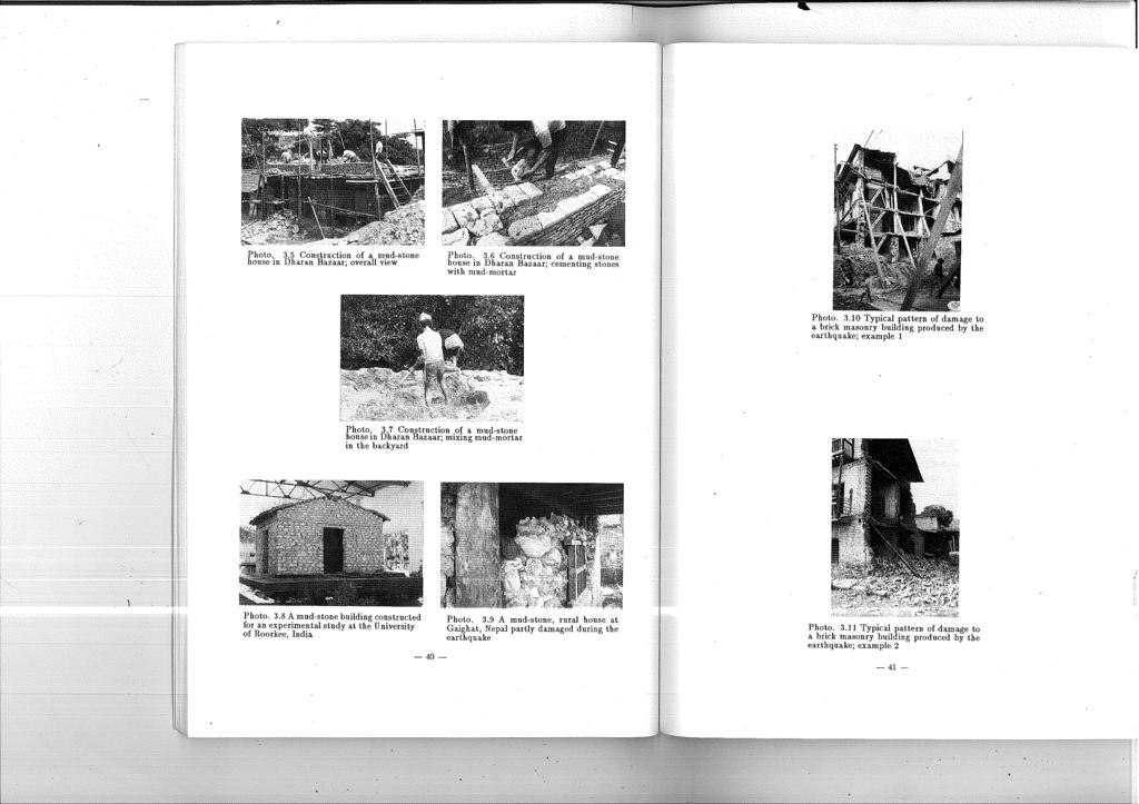
3 Photo. 3.3; the staircase positioned along the transverse axis of the building. The stiffness of a staircase, even one of wooden construction, improves the stiffness of a building in the transverse direction and helps it to resist lateral load during an earthquake Structure of mud-stone buildings Photo. 3.1 Interior view of the floor slab system of a damaged brick masonry house Photo. 3.2 Cross-sectional view of th~ floor slab system of the same damaged buck masonry house In rural regions of India and Nepal, what"are called mud-stone buildings are common. Their construction is very simple: Stones piled up to form the exterior and interior walls are cemented with a clay-mud mortar. In the house under construction which we examined in Nepal, they were using day mud without a reinforcing material. Photos. 3.5 through 3.7 show the construction process. Note that the mud-mortar being mixed in the backyard (Photo. 3.7) contains no straw or cloth for reinforcement. A mud-stone building typical of rural regions (Photo. 3.8) has been constructed at the Department of Earthquake Engineering, the University of Roorkee, India for use in experimental studies. A dose-up of the mud-stone wall of a rural house partly damaged during the earthquake is shown in Photo General description of the damage done Photo. 3.3 Interior view of (he. floor slab system of a bnck masonry building Photo. 3.4 Exterior view of the ftoor slab system of the same bnck masonry building The damage done to clay brick masonry houses and to mud-stone houses was severe. The pattern of damage being the collapse of the brick masonry or mud-stone walls followed by the collapse of the heavily weighted floors and roof slabs made of day bricks covered with a layer of mud. Because the ductility of the walls against lateral loading is poor, t.he collapse of such' buildings may be abrupt thereby resulting in a large number of casualties. The typical pattern of damage for brick masonry buildings is the collapse of the gable walls (Photos and 3.11). This pattern was seen at almost every site of damage in Nepal; but in damaged sections of Bihar State, India it was absent. One reason may be that the intensity of the shock experienced in the Indian area was not high enough to produce this kind of structural damage. The typical damage pattern for brick masonry structures was seen in buildings of two or more stories, possibly because the gable walls of such buildings are exclusively selfsupporting, there being no connecting seismic component. As shown) the wooden beams run transversely, and no specific seismic structural components are positioned to strengt.hen the gable wall. Therefore when out-of-plane lateral forces are applied in the longitudinal direction, the gable wall sloughs off (Photos and 3.11). Lack of stiffness in the floor slab system, in particular longitudinally, might cause major deformation during excitation and thrust the gable wall into an out-of-plane position
4
 Patna Patna, the capital of Bihar State, is located at the confluence of the Ganges and Sone Rivers about 860km east-southeast of Delhi. The distance of Pat.")
5 3.2.4 Damage in the stricken areas The damage done to buildings seen in the stricken areas visited during our field survey is summarized as follows: (a) Patna and Darbhanga: Bihar State, India (a.1) Patna Patna, the capital of Bihar State, is located at the confluence of the Ganges and Sone Rivers about 860km east-southeast of Delhi. The distance of Pat.na from the reported epicenter of the earthquake is about 200km. Because the epicenter was iar {Torn the city, there was no serious damage done. The Ina-in office of the State Government Secretariat, built in 1912 of brick masonry, is shown in Photo The only damage to this building was the cracking of its floor slabs and the peeling off of a small amount of plaster-finish coating of a w~b (Photo. 3.13). Photo The State Government Secretariat Main Office, Patua, India Phot.o Peeling off of the finish on a wal). in the State Government Secretariat Main Office, Patna (a.2) Darbhanga Darbhanga is about 100km northeast of Pat.na. It and Madhubhani, both district headquarters) are almost on a line from Patna to the reported epicenter. The distance to the epicenter from Darbhanga is 100km and from Madhubhani 60km. Photo shows the damage done t.o a kiosk in the backyard of the District. Headquarters Office. Shear cracks have appeared in its brick masonry walls and roof tiles have fallen, but the building has not collapsed. The District Headquarters Office has a large number of serious cracks in it.s brick masonry walls (Photo. 3.15), but it. remains open for general business. Int.ernal damage to the residence and to t.he office of tho Civil Sergeant, Darbhanga Dist.rict was severe (Photo. 3.16); both buildings have been closed. Damage to an entrance of t.he dormitory at the Medical College Hospit.al is shown in Photo Photo gives a close-up view. There are no reinforcing bars for the girders and beams, nor for the floor system composed of layers of bricks and mud. building consequently is extremely heavy and has poor ductility for deformation. Numerous cracks have appeared within the dormitory in its transverse walls and in its longitudinal walls around t.he windows and doors. Note t.hat. t.he one-story buildings located less than 20m from the damaged dormitory show no exterior seismic damage, not even small cracks around their window frames (Photo. 3.19) The PIlOtO A damaged kiosk in the backyard of the Darbhanga District Headquarters Office, Darbhanga, India Photo The damaged Civil Sergeant's Residence, Darbhanga District, Darbhanga Photo Cracks on the brick masonry wall in the Darbhanga District Headquarters Office, Darbhanga

6 Photos and 3.21 show vividly the damage done by the earthquake in Darbhanga District.. (b) Kathmandu and Bhaktapur: Bagmati Zone, Nepal (b. 1) Kathmandu Photo The damaged Medical College Hospital) Darbhanga Photo Close-up of a cross-sectional view of the damaged Medical College Hospital. Darbhanga Kathmandu is the capital of Nepal and headquarters of the Kathmandu District, Bagmati Zone, Central Sector. Thereport.ed epicenter was approximately 150km southeast of the city. Alt.hough a small number of injuries were reported in the newspaper! Rising Nepal} we found no structural damage caused by the 1988 Earthquake during our survey. (b.2) Bhaktapur Photo Undamaged buildings located close to the damaged Medical College Hospital, Darbhanga Bhaktapur is the headquar-ters of Bhakt.apur District, Bagmati Zone and is about 10km east of Kathmandu. The epicenter was about 140lan east-southeast of this town. The damage in Bhaktapur is concentrated in the old town which is spread Over the hillside (Photo. 3.22). The buildings damaged by the 1988 Eart.hquake are t.hose which were not effect.ed by a previous one in January Buildings reconstructed after t.hat eart.hquake have not. been seriously damaged by recent earthquakes. The typical damage pattern from the 1988 Eart.hquake, the collapse of gable walls, is present in Bhaktapur. Photos and 3.24 show such collapses. Photo shows a wall that has expanded in the out-of-plane direction and is indicative of the hazard of sudden collapse. These photographs also show the construction system used in brick masonry buildings. Bricks have been piled up and cemented to form an exterior wall that is almost 500Ihm t.hick by placing four bricks side-by-side. A wooden frame has been built in the longitudinal direction within t.he space formed. Photo shows wooden beams placed in the longit.udinal wall. Not.e the wooden st.aircases positioned transversely. (c) Gaighat., Udayapur District, Sagarrnatha Zone, Nepal Photo Damage in the Darbhanga area, view 1 (courtesy of the Building Construction Department, Government of Bihar) Photo Damage in the Darbhanga area, view 2 (courtesy of the Building Construction Department, Government of Bihar) Gaighat is located within the reported epicentral region of t.he 1988 earthquake about 35km north of the Mehandro Highway which runs almost due east-west along t.he foot of the Himalaya Mountains. Although the town is the headquarters of Udayapur District, it is very small. Along t.he road to Gaighat. we found a large number of liquefaction spots, and within the town several houses built of brick masonry or of stones cemented with mud-morta.r

7 that showed seismic damage. Photos and 3.27 record some of the damage done in Gaigha.t; the former shows the typical collapse of the gable wall of a brick masonry farm house, and the latter the' fallen wall stones of a mud-stone farm house. Both houses are two-storied, the upper story having a wooden frame. These wooden second stories were not seriously damaged. Inhabitants of a small village to the west of Gaighat told us that the shock was very frightening and that almost all the roof tiles were dislodged. (d) Dharan, Sunsari District, Kosi Zone, Nepal Photo Damage zone in the old town, Bhaktapur Photo Collapse of the gable wall of a brick masonry building; example 2, Bhaktapur, Nepal Photo Collapse of the gable wall of a brick masonry building; example 1, Bhaktapur, Nepal Photo The expanded wall of a brick masonry building, Bhaktapur 1 Nepal (d.1) Dharan Bazaar Dharan Bazaar is located on the border between the Himalaya Mountains and the Tera.i, the plain at the foot of the mountains. Although Dharan is not the headqua.rters of the district, it is one of the largest bazaars for the exchange of products from tho mountains and plain. It is about 75km east-northeast of the reported epicenter. Our observations of seismic damage indicate that the actual epicentral region, the center of maximum energy release of the 1988 earthquake, must have been located closer to Dharan or Dhankuta. The newspaper Rising Nepal of September 15, 1988 gave the number of houses destroyed as 1,626, and the number partially damaged as 773. A total of 787 dangerous buildings were demolished by the Army or the Police. The estimated loss of property totaled million Nepalese Rupees, the equivalent of U.S. $10 million. Damage done to Dharan Bazaar is shown in Photos to The nurses' headqua.rters at Dharan Hospital(Photo. 3.28) has been reduced to a pile of bricks; whereas, the yellow-colored emergency ward next to it is without serious damage. Beyond the demolished nurses' headquarters, an elevated reinforced concrete water tank stands undamaged. Examples of the total collapse of brick masonry houses are shown in Photos through A pile of logs tha.t had been wooden beams in a collapsed brick masonry house is shown in Photo The exposed ends of these logs have rotted with a.ge, which may have been why this house collapsed. (d.2) British Army Recruit Camp Photo A damaged brick masonry farm house, Gaighat, Nepal Photo A damaged mud-stone farm house, Gaighat. Nepal The site of the British Army Recruit Camp is near Dha.ran Baaaar. Buildings within the camp, mostly single-story cement block structures, were damaged (Photo. 3.32). An administrative officer at the Camp informed 11S that the buildings were constructed to the seismic design specified in the U.K. code, but that their construction had not been certified by an appropriate engineer

8 Photo Collapse of a brick masonry building: the nurses' headquarters, Dharan Hospital, Dharan Bazaar, Nepal Photo A collapsed brick masonry house; example I, Dharan Bazaar, Nepal Photo Damage to a single-story block building in the British Recruit Camp, Dharan Bazaar, Nepal Photo A collapsed brick masonry house; example 2, Dharan Bazaar, Nepal Photo A collapsed brick masonry house; example 3, Dharan Bazaar, Nepal Photo Shear failures in the short-span brick masonry wall of a special classroom, the Engineering College Campus, Tribhuvan University, Dharan Bazaar, Nepal -48- Photo Seriously and slightly damaged classroom buildings, the Engineering College Campus, Trlbhuvan University, Dharan Bazaar, Nepal - 49-

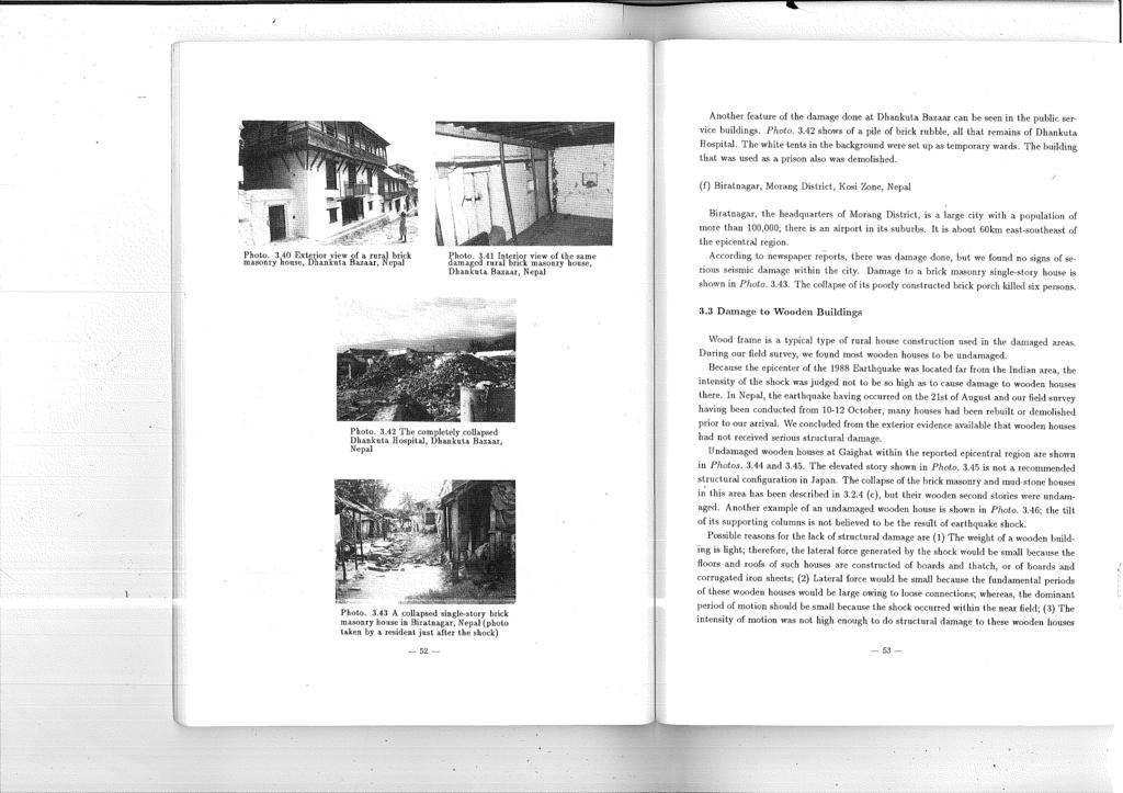
9 (d.3) Engineering College Campus, Tribhuvau University The Engineering College Campus of Tribhuvan University, Dharan is in the suburbs of Dharan Bazaar. It has several brick masonry buildings that are used for class rooms and laboratories. A single-story canteen was not damaged, but its two-story buildings, including the library, were. Serious shear failures arc present in the short-span walls containing window frames(photo. 3.33). On this campus, buildings of identical construction are oriented in east-west and northsouth directions. Our survey showed that serious damage was produced by excitation in the east-west direction. The intensity of east-west motion (parallel to the Himalaya Mountains and corresponding to the direction perpendicular to the probable subduction movement of the fault) would be higher than that of north-south motion (perpendicular to the Himalaya Mountains and parallel to the subduction movement. of the fault). The building seen in the foreground of Photo has suffered no damage to its short-span walls; whereas, the one in the background has severe cracks in its east-west wall. Photo: Damage zone in Dhankuta Bazaar, Nepal (e) Dhankuta, Dhankut.a Dist.rict, Kosi Zone, Nepal Dhankuta District is north of Sunsari District. The town of Dhankuta Bazaar, its headquarters, is within the mountain area. and 20km north of Dharan Bazaar. Between Dharan and Dhankuta, roads had to be closed at several places for reconstruction because of landslide damage. Dhankuta Bazaar is spread over a gently sloping hill (Photo ). The typical damage done to ga.ble walls of brick masonry constructions, is seen in Photos to Almost every brick masonry building showed some seismic damage to its gable walls. The damaged brick masonry buildings in Dhankut.a Bazaar had all been roofed with thatch or corrugated iron sheets. Because these t.ypes of roofs are light. in weight, tho collapse of gable walls would be due to lateral forces produced from their own weights because such walls are constructed to be almost self-standing and are peeled off a building when lateral force is applied in the out-of-plane direction. Provided that such lateral force can be carried by wooden floor beams, longit.udinal wall components, or both, gable walls of brick masonry buildings would not be seriously damaged. Almost. every building in Dhankut.a Bazaar appears to have been harmed by the 1988 eart.hquake. The house shown in Photo does not. look seriously damaged. Its exterior facade may have been reconditioned; the interior, however, shows large cracks in the walls (Photo. 3.41). The inhabitants told us t.hat blocks of wall fell during the earthquake. Photo Damage to t.he gable wall of a brick masonry building; example 1, Dhankuta Bazaar, Nepal Photo Damage t.o the gable wall of a brick masonry building; example 3, Dhankuta Bazaar, Nepal Phot.o Damage to t.he gable wall of a brick masonry building; example 2, Dhankuta Bazaar, Nepal Photo Damage to the gable wall of a brick masonry building; example 4, Dhankuta Bazaar, Nepal
10
11 whose seismic capacities we had concluded were not great. 3.4 Damage to Reinforced Concrete Buildings Structure of reinforced concrete buildings Photo An undamaged rural wooden house; example 1, Gaighat Photo An undamaged rural wooden house; example 2, Gaighat There were few reinforced concrete buildings found within the damage areas surveyed. The most widely used method of construction for reinforced concrete buildings is a reinforced concrete frame with filled-in walls of brick masonry. We found no steel frame buildings during our field survey. The Indian Standard for strueturaldesign includes seismic design provisions based on an ultimate strength design procedure [Ref.3.1]' These standards have been used exclusively for federal and state public buildings, not for small scale private construction. In Nepal, they are now establishing structural standards, but have also used established standards such as those of the U.K. or India. In most cases, structural designs a.gainst dead and live loads have been made without incorporating specific processes for lateral loads. A typical reinforced concrete building under construction in an area damaged by the earthquake is shown in Photo It consists of reinforced concrete frames with filled-in walls constructed of day bricks. This building will be two-stories high. The dimensions are about 20x20cm for a column and about 10x20cm for a girder. The quality of the concrete being used is not high. The reinforcing steel bars are cold-formed, deformed bars with diameters of about 0.5 inches. The tie bars used in the columns are spaced about 25cm apart. Another example of a typical reinforced concrete building is shown in Photo A reinforced concrete building is being constructed for use as a ward at Dharan Hospital, where several brick masonry buildings were demolished (Photo ). Its construction has beeninterrupted for lack of funds. This building will be 36m long with 6 longitudinal spans and 18m wide with 3 transverse spans. The dimensions of the columns used are 36 x 10cm. Three tensile reinforcing bars 0.75in(19mm) in diameter are positioned longitudinally and two bars transversely (Photo. 3.50). A Nepalese building engineer told us that they would construct brick masonry walls in the transverse direction. For reinforcement, the tie bars used in the columns in order to resist lateral loads are about. 0.38in. (9mm) in diameter and spaced about 30cm apart Damage done in the stricken areas Photo An undamaged rural wooden house; example 3, near Biratnagar, Nepal No notable damage was seen in the few reinforced concrete buildings checked during our - 55-

12 field survey, which led us to conclude that the intensity of the shock was not great enough to damage a reinforced concrete building. But, because theso constructions do not have great lateral strength, and have only a small amount of tensile reinforcement as well as an inferior ductility with only a small amount of shear reinforcement, their seismic capacities would not be sufficient to protect them from severe excitation. Should a shock with an intensity higher than that of 20 August 1988 be experienced, catastrophic damage leading to complete collapse similar to that observed for brick masonry buildings might well take place, Photo A reinforced concrete buil~ing under construction in Bihar State, India Photo A reinforced concrete building under construction in Biratnagar, Nepal Summary of the survey of reinforced concrete buildings: (a) Darbhanga, Bihar State, India A two-story reinforced concrete building next to the Civil Sergeant's brick masonry residence is shown in Photo. 3.51, the latter having had severe internal damage (Section and Photo. 3.15). There was no notable damage to this 2-story building: rnoroover, a twostory reinforced concrete building next to the Civil Sergeant's Office suffered uo damage. as judged from our exterior examination. (b) Dharan Bazaar, Nepal Photo A reinforced concrete building under construction at Dharan Hospital, Dharan Bazaar, Nepal Photo Reinforcement of the steel bars in the building under construction at Dharan Hospital, Dharan Bazaar, Nepal A ward of Dharan Hospital is shown in Photo At this place both the residence of the chief superintendent and the nurses' headquarters (both constructed of brick masonry) collapsed completely, and here a ward that is under construction has been described(.3a.1). There was no structural damage, not even small cracks around window frames. A shear wall positionedlongitudinaily(photo. 3.53) is not even slightly cracked. The partition wall constructed of brick masonry that is parallel to the reinforced concrete wall shows a long deep crack (Photo. 3.54) which indicates that the lateral force generated could be carried by the reinforced concrete shear wall. A two-story building used as the medical office showed slight damage to its exterior staircase (Photo. 3.55). The two-story telecommunications office in Dharan, built with a reinforced concrete frame and a partially filled in brick masonry wall, is shown in Photo Our exterior examination showed that there was no external damage. The foregrouud of Photo shows the rubble of a nearby brick masonry building. Private buildings (Photos and 3.58) showed no signs of seismic damage. Photo gives a close up of the top of a column. Generally, when subjected to a major earthquake, cracks form at the corners of such column-girder connections, but none are present

13 Photo An undamaged reinforced \ concrete building located next to the Civil Sergeant's Residence, Darbhanga District, Darbhanga, Nepal Photo An undamaged reinforced concrete ward at Dharan Hospital, Dharan Bazaar, Nepal Photo An undamaged reinforced concrete private horne; example 1, Dhatan Bazaar, Nepal Photo An undamaged reinforced concrete private home; example 2, Dharan Bazaar, Nepal Photo A reinforced concrete shear wall positioned within the ward longitudinally, Dharan Hospital, Dharan Bazaar, Nepal Photo Shear cracks in a brick masonry wall placed within the ward parallel to the undamaged reinforced concrete shear wall (Photo. 3.53), Dharan Hospital, Dharan Bazaar, Nepal Photo Close-up of the top of the column of a third reinforced concrete private home, Dhatan Bazaar, Nepal Photo An undamaged reinforced concrete private home, Dhankuta Bazaar, Nepal Photo The damaged two-story reinforced concrete medical office at Dharan Hospital, Dharan Bazaar, Nepal Photo The telecommunications office, Dharan Bazaar, Nepal
 Biratnagar, Nepal A six-story hotel is being constructed in downtown Biratnagar.Photo. 3.61 shows an, exterior view of it.")
14 here. (c) Dhankuta Bazaar, Nepal There are a few reinforced concrete buildings in Dhankuta Bazaar, one of which is shown in Photo No seismic damage was done to this house. (d) Biratnagar, Nepal A six-story hotel is being constructed in downtown Biratnagar.Photo shows an, exterior view of it. The frame is constructed of columns and beams of reinforced concrete with filled-in walls of brick masonry (Photo. 3.62). The dimensions of the original columns are 12x 12in (30x30cm). According to construction engineers at this site, because of cracking that took place during the earthquake, the columns for both the first and second stories have been enlarged to 60x60cm (compare Photos and 3.62). The beams examined had a thickness of about 30cm, and the concrete floor slab a: thickness of locm. The arrangement of the reinforcing bars is seen at the top of the building (Photo. 3.64), where the bars have been left exposed for possible future extension of the building; a common practice in the areas we visited in Bihar State, India and in Nepal. The arrangement of the tensile and shear tie reinforcing bars is shown. Six cold-formed tensile bars with diameters of about 0.5in(12mm) are positioned within a 30x30cm cross section. The ratio of this cross sectional area to the total column area (Pg) is about The shear reinforcing bars, about 4 to 5mm in diameter, are spaced 20cm apart. The shear reinforcement ratio (p,) is approximately Photo Exterior view of the six-story hotel under construction at Biratnagar, Nepal Photo Interior view of the six-story hotel under construction at Biratnagar. Nepal 3.5 Seismic Capacity of a Building in the Earthquake-damaged Area Evaluation of seismic capacity We evaluated the seismic capacity of a building in the area struck by the 1988 Earthquake in order to determine the intensity of ground motion during the shock. The results have been used to make recommendations for the improvement of the seismic capacities of buildings against future earthquakes. As the buildings examined during our field survey constructed of brick masonry, mudstone, or a reinforced concrete frame with filled-in brick masonry 'walls have inferior ductility, we have been able only to estimate the strength of a building in our determination of its seismic capacity. Lack of other pertinent information, such as drawings of building plans Photo Enlarged columns on the first and second story levels of the six-story hotel under construction at Biratnagar, Nepal Photo Arrangement of the reinforcing bars for a column of the six-story hotel under construction at Biratnagar, Nepal
15 and calculation notes, means that the evaluated strength is only roughly representative of the actual seismic capacity of a buildiug Brick masonry aud mud-stone buildings (a) Brick masonry buildings The strength of this type of building geuerally can be determined from the strength of the cement or mud-mortar used. The compressive strength of a burnt clay brick taken from an existing brick masonry building constructed in Japan in 1914 is reported to be approximately 300kg/cm'. The shear strength of its mortar made with cement:lime:sand (1:1:5) is in the range of kg/cm', but shear strength values fluctuate greatly with the type of mortar used. The respective compressive and shear st.rengths of a brick masonry wall of this Japanese building are llo-170kg/cm 2 and about 7kg/cm 2 with a deflection angle of 1.7x10⁻³, this last value varying greatly with the amount of normal stress [Ref.3.2J. The ultimate shear strength of a brick masonry wall from another building in Japan has been reported to be about 3kg/cm 2 The type of earthquake damage common to brick masonry buildings is the collapse of a gable wall in the out-of-plane direction. Let a gable wall be represented by a self-supporting panel of height H, length L and thickness t as shown in Fig And, let w denote the unit weight of the brick masonry gable wall. The axial force, No, at the bottom of the wall is obtained from Fig. 3.2 Analytical model of a gable wall represented by a self-supporting panel N o N o No = whlt (3-1) M o M o Assuming that the rigidity of the wall is nearly infinite, we can estimate the overturning moment, M o, at the bottom of the wall from Eq.(3-2). u, = cwh'lt /2 (3-2) in which c is given by (3-3) in which a o denotes the peak acceleration of the ground motion and G the acceleration of gravity, 980cm/sec 2 Assuming that deformation at the cross-section is linear (following the Bernoulli-Euler approximation) and that the stress block at the cross section can be represented as linear, as shown in Fig. 3.3.(a) ( i.e., the stress-strain relation remains linear- elastic), we can obtain the fiber stress on the tensile end from: Fig. 3.3(a) Triangular stress-block at the bottom of a gable wall that corresponds to the linear elastic condition Fig. 3.3(b) Rectangular stress-block at the bottom of a gable wall that corresponds to the ultimate condition
 is given by Substituting t = 45.7cm (18in.")
16 Suppose that the wall collapses in the out-of-plane direction when the fiber stress equals zero (i.e., the tensile strength of the cement or mud mortar would be zero), then coefficient c in Eq.(3-3) is given by Substituting t = 45.7cm (18in.) for the average thickness of the wall, and assuming each story of the building to be 3 meters high, = No/(Lt) - Mo/(l/6Lt') = wh - 3cwH'/t c = t/(3h) c = 0.33 x 45.7/(300 x n) = 0.05/n in which n is the number of stories in the building. (3 -.1) (3-5) (3-6) If we assume that the stress block at the bottom of the wallis rectangular (Fig. 3.3(b)), rather than triangula.r (Fig. 3.3(a)), coefficient c in Eq.(3-3) becomes in which a c is the ultimate compressive strength of the brick masonry wall. Assuming that w equals 2ton/m 3, and ", equals 100kg/cm 2, and substituting t = '15.7cm and 11 = 300ncm, we obtain the relation c = c = t/h(i- wh/",) (1-6n/l000) x 0.15/n '" 0.15/n (3-7) (3-8) Provided that our condition that a gable wall is self-supporting is realist.ic, Eq.(3-6) gives a possible minimum coefficient c, and Eq.(3-8) a possible maximum coefficient. When the shear capacity determines the strength of the wall, coefficient c is given by c = r,/(wh) (3-9) in which, r, is the shear strength of the brick masonry wall. \Vhen r, equals lkg/cm 2, w equals 2ton/m 3, and H equals 300n ern, coefficient c is given by The strength of the wall against the overturning moment in the ou t-of- plane direction is given by Eq.(3-6) or (3-8) depending on the stress distribution assumed, and the strength against the shear force is given by Eq,(3-10). Taking into account that the gable wall is fastened to a wooden roof and a floor slab framework, or to brick masonry walls posit.ioned longitudinally, the strength of the wau against. the overturning moment will be larger than that given by the above equations because the wooden framework would cramp the top of the wall against deflection, The seismic capacity of the wau against. the shear force will be less than that given by Eq.(3-10) because a 'certain amount of lateral force is applied by both the roof and floor slab frames. This quantitative discussion cannot be extended because we cannot evaluate the behavior of the wooden frames or walls-in the longitudinal direction, The actual damage observed is evidence that the seismic capacity of a gable wall is determined from its resistance to the overturning moment which produces the out-of-plane deformation. The resulting coefficient c is for n equal to unity, ,075 for n equal to 2, and ,0.5 for n equal to 3, (b) Mud-stone buildings For mud-stone buildings, a discussion similar to that made for brick masonry buildings holds true. (c) Concrete block buildings lu the British Army Recruit Camp at Dharan, Nepal, a group of reinforced block masonry buildings suffered seismic damage (described in 3.2.4). As shown in Photo.,3..32, cracks were generated aiong the joint mortar between the blocks. We have several architectural drawings for these buildings that give the dimensions and the rough arrangement of the reinforcing bars. Because our observation of the damage done to the buildings revealed shear failure of the mortar joints between blocks, we can estimate the shear strength of a concrete block building in the transverse direction as follows: Let the dimensions of a typical building in the Camp be 100ft by 22ft 4in (.10.5x6.8m), Within that building, seven shear wails constructed of hollow concrete blocks 8in (20cm) thick are positioned transversely. The length of each wall is about 16ft 8in (5m). Suppose that the building has a set of seven shear walls; on the average one shear wall should support the lateral fo.rce, Q, given by c = 1.7/n (3-10)
17 = 30c (ton) (3-11) strength of the concrete, which we found to be lean, is 180kg/cm 2 in which c is the coefficient given by Eq.(3-3) when the weight of the building averages Iton/rrr'. Suppose the shear strength of the concrete block masonry wall to be 1.5kg/cm 2 [Ref.3.3], On this basis, the flexural capacity, My, can be estimated as follows [Ref.3.4]; My = 0.8atO"yD + 0.5ND(l - N/bDF',) (3-14) then the maximum shear capacity of the wall, Qmax., is in which at is the cross-sectional area of the tensile bar, O"y the yielding strength of the reinforcing bar, D the depth and b the width of a column, N the axial force, and F, the by which, taking into account penetration for window frames and doors within the wall, we have estimated the effective cross-sectional area of the wall to be half that of the gross cross-sectional area. When the lateral load to the wall equals its maximum shear capacity, coefficient c is Q = c x 30.5 x 6.8 x 1.0/7 Qma" = 1.5 x 500 x 20/2 = 7,500 (kg) (3-12) order to estimate the strength of a column; (1) The average weight of the building per unit area is ldton/rn? based on the floor slab at the t.op of the building being 10cm thick; (2) The yield st.rength of the cold-formed tensile bars is 4,000kg/cm 2 ; and (3) The compressive compressive strength of the concrete. Substitution of at = 3.81cm', O"y = 4000kg/cm', D = b = 30cm, N = 60ton and Fe = 180kg/cm' in the equation, gives a flexural capacity for a column on the first story of Suppose the clear span column Qmy is My = 9.3 (ton m) (3-15) of a first-story column to be 4m, then t.he lateral capacit.y of The assumed value of the shear strength of the block masonry wall or of the average weight of the building in Eq.(3-11) or (3-12) could produce a much lower coefficient c than the value given by Eq.(3-13). The estimated coefficient c given by the Eq.(3-13) is larger than the actual value, if any, because the damage to concrete block masonry buildings seen in the Camp was not severe enough to produce the complete collapse of the joint mortar due to shear failure Reinforced concrete building c = 7.5/30 = 0.25 (3-13) In Biratnagar, Nepal, a six-story reinforced concrete hotel is under const.ruction (described in 3.4.2). This building has been reported to have had some cracks in its columns; therefore, the colnmns on both the first and second floors were enlarged from 12 to 24 in (30 to 60cm). We estimated the seismic capacity of the original building against lateral force. The plan of the hotel shows a length of about 20 meters with 5 spans and a width of about 12 meters with 3 spans. As a result, each column on each story supports an average floor area of 10m 2. The arrangement of the reinforcing bars has been reconstructed from Photo There are three tensile bars, each with a diameter of about 13mm, and shear reinforcing bars positioned about 20cm apart. The following conditions were assumed in Provided that the dynamic amplification factors for t.his six-story building are assumed to be unity for the approximation in this estimation, the corresponding base shear coefficient obtained from the lateral capacity given by Eq.(3-16) is Based on the assumption that the shear strength is 9kg/cm 2 ca.p~.city of the column Qsy is Qm. = 2My/ H = 4.7 (ton) c = 4.7/60 = Estimation of seismic intensity based on building responses (3-16) (3-17) for concret.e, the shear Q,y = 8.1 (t.on) (3-18) This indicates that. the seismic capacity of t.he column can be determined from the flexural capacity given in Eq.(3-16). Provided that half of any lateral force applied during the earthquake would be carried by the brick masonry walls that fill in the frame, the seismic capacity of the building would be twice as large (c = 0.16) as the value given in Eq.(3-17). Our examinations of the apparent damage to and the evaluated seismic capacity of a building enabled us to estimate the probable seismic intensity of the ground motion in
18 Table 3.1 Estimated seismic intensity during the 1988 Nepal-India Earthquake shock of 21 Angnst 1988 Place of Dama.ge Bhaktapur Gaighat Dharan Bazaar British Army Recruit Camp, Dharan Dhankuta Bazaar Biratnagar Estimated Intensity (acceleration in gal) Remarks Gable walls of 3-story high buildings collapsed but a large number of brick masonry buildings suffered no serious damage. Brick masonry and mud-stone houses of 2-stories high were damaged. Wooden houses did not suffer serious damage. A large number of brick masonry houses l 2-st6ries or higher, collapsed completely. Wooden houses and several reinforced concrete buildings suffered no serious damage. Serious shear cracks appeared in one-story high concrete block buildings. A large number of gable walls collapsed. A few gable walls that were one-story high collapsed; but, some 2-story high ones did not collapse even though serious crack appeared. A 6-story reinforced concrete building suffered cracks but no serious damage. Some poorly constructed brick masonry houses were damaged. the areas damaged during the earthquake. Obviously, our estimate of the intensity must include a fair amount of variation because of the hypothetical assumptions made throughout the analysis. The estimated seismic intensity at selected points, expressed in terms of ground acceleration, is tabulated in Table Statistics on the Damage Done in Dharan Bazaar To establish the distribution of the types of buildings damaged, we surveyed.500 houses in Dharan Town Panchayat, Sunsari district, Nepal, on the border between the hill area and alluvial plain, it being theplace most damaged. The population is 118,218 and the number of houses about 20,000. The town is divided into 19 administrative wards.the data for the physical and human losses by ward for the 1988 earthquake, obtained from the Dh aran administrative office, are tabulated in Table 3.2. The total of lives lost in this town was 122, about one-sixth of the total earthquakerelated deaths in Nepal. Collapsed buildings numbered 1671, about one-eighth of the total buildings destroyed in the country. A map of Dharan Bazaar, with ward numbers encircled is shown in Fig Dharan town hospital marked [H] (shown in Photos. 3.28, and 3.53) is located in ward 4, and the British Army Recruit Camp (described in section 3.4.2) is in ward 18. Our basic area of research consisted of wards 1 to 5 (shaded in the figure) which make up the center of Dharan Bazaar, the most heavily damaged area in the town. We checked the number of stories and the type of construction used for each house along the two main streets with the assistance of Ms. S. Mallo" Chief Engineer of the Nepalese Government, and Messrs. S. Sharma and J. Satyal, translators, and the residents. numbers of collapsed, damaged and undamaged buildings classified by building material and the number of stories are shown in Table 3.3 and Fig One-third of the buildings in these wards are constructed of brick masonry and one-third of wood. Engineered bnildings of reinforced concrete and reinforced concrete fined-in brick walls make up about one-fourth of the total number of buildings. The No mud-stone houses were found. Our information shows that more than 80% of the three-story brick masonry buildings, 50% of the two-story brick buildings, and 30% of the single- story brick buildings collapsed, but that most of the wooden houses survived and no reinforced concrete buildings collapsed. This indicates that reinforced concrete buildings and reinforced concrete buildings with filled-in brick walls are relatively strong because of the rigidity of their floor slabs and that the frequency characteristics of the input ground motion might be much higher than the fundamental frequency of the wooden houses. Unfortunately, there is no available acceleration record for this area, Damage ratios for such hill areas as Sunsari, Dhankuta, Ham and Panchthar districts, however, provide evidence for our supposition
19 TO DHANKUTA Table 3.2 Material and human loss caused by the 1988 Nepal-India Earthquake in Dharan Town I'anchayat, Sunsari District, Kosi Zone.Nepal Population No. Houses No. Wards Damaged pamage Category oss Yard beaths louses Domo Let e artial 000 Rs. 1! ! ~ I I I atal I I BRITISH CAMP QJ) Death Ratio = 122*100/ = 0.108% Damage Ratio =4275*100/ = 21.4% Complete Damage Ratio =1671*100/20000 = 8.4% Rs. = Rupees TO BIRATNAGAR Fig. 3.4 Map of Dharan Bazaar Table 3.3 Statistics on building damage in wards 1-5 in Dharan Bazaar Damage Wood Wood & Brick RIC Brick RIC Total if 2F Brick IF 2F 3F- IF 2F 3F IF 2F Total Number _.- Collapsed I 107 Half Collapsed I I 24 3 I 5 I 62 Cracked I I 6 48 Ti!ted No Damage Coi lapse Ratio % Damage Ratio %
20 Table 3.4 Damaged facilities and estimated monetary loss in Dharan Bazaar No. of bufldfngs 50._._--- \\\\\1 Col-lapsed [] Damaged ---._-_._ '\ :j;:' \ Damage % :c:: \ }: \ 1\ :::. \ I \. V._.\..._. \ Collapse '% \ Damage ratio 100% 50% Category A. Government Facilities B. Semi-Governmental Offices C. Educational Establishments 0. Schools I E. Hospitals and HealthOffi.C.e1 1F. Social Organization G. Major Temples and Mosques H. Private Houses I ~umber of ~urnber of ~acilltiespamaged buildings ' [ 23 4p5 118~18 people effected by the earthquake ame ee Category pomplete artial 34 o , I 2,604 4,625 2,370 11,239 2,,514 1, ; ,507 Rs. :::: Rupees \ No. of buildings Story Material 1 2 Wood Wood & Brick Brick RIC-Brick 1 2 Ric Fig. 3.5 Damage classified by the construction material and number of stories of a building Q. No. of deaths I No. o-f collapsed buildings No. of deaths Table 3.5 Types of assistance received from Dhatan Town Panchayat Item Rice Medicines Instruments Water Containers Fuel Food for Volunteersand Drivers Plastic Iron and Cotton Ropes Given to Ward Relief Committee StationarY and Other ;~oods Total Rs ,I.,\, \ /' " I \ I \, 200 'J ~amage I \ I ( 10%) \ / \ / V / ~ /"'" Fig. 3.6 Numbers of collapsed and damaged buildings and deaths per ward, in Dharan Town Panchayat Other help from Dharan Town Panchayat (1) Exemption of registration fee for reconstruction (2) Exemption of tax on construction materials Table 3.6 Types of assistance received from the central and district governments entral overnment unsari istrict anchayat Cash Rice Other Blanket/Tentsl Corrugated Iron Plastic Relief Cash to Kin of the Dead Total Rs Quintal Binding 791 (1 quintal=112 Lb) (1 bind.=15 sheets) 1000 Rs./dead Rs. Hs. :::: Rupees -73 -

21 (see section 4.1). On the assumption that the dimensions of a typical brick masonry building ate,5x6m 2 ; a unit, 3-m story height; a wall thickness of 50 em; an average weight of 1000kg/m'; and an ultimate shear stress of fired brick of kg/cm', the shear capacity of the first story is estimated to be tons for a wall 350 cm long. The approximate respective total weights are 30, 60 and 90 tons for one-, two- and three-story buildings. As stated, half of the two-story and most of the three-story brick masonry buildings in Dharan Bazaar collapsed. Taking this into consideration and assuming a magnification factor of 1.5, t.he maximum acceleration of the ground motion was cm/sec 2 The ultimate stress of adobe is about kg/cm', less than that for fired brick, but similar to the value for mud-stone; and, as it is similar to the values obtained from other estimations (see sections 2.3, 2.4, 2.5 and 3.4) it explains why severe damage was done to buildings of mud-stone construction. The relation between the number of dead and the number of damaged buildings per ward is showu in Fig The rat.io of deaths to collapsed houses, marked by circles, is roughly 10%. A detailed explanation is given in the next section. The estimated value of lost property in Dharan Panchayat was 312 million Nepalese Rupees (equivalent to U.S. $13 million), about 90 % representing the cost of damage to private houses (Table 3.4). According to the report by S.P.Gupt.a [Ref.3.5], the total loss in Nepal amounted to 827 million Nepalese Rupees (U.S. $3'1 milliou). The monetary assistance received from Dharan Town Panchayat and the central government is tabulated in Tables 3.5 and 3.6. Relief cash to families of the dead from Sunsari District was 1000 Rs/dead person (U.S. $ 40 ). i~mi6toi9,. i "M27 TO 32. ""...00 "''''''''"0 ~WAY ;»''''0 0 C'USEO To, c<: S MID OJl\fE~lS... -CAI~~A1 ROAD,~""2TOI8 ( H H 3.7 Damage to Roads and Bridges in Nepal There are two main roads in the earthquake-stricken area in Nepal; the Mehandro (Eastwest) Highway and the Dhankuta-Dharan-Jogabini road. Mehandro Highway is a blacktopsurfaced one lane road that runs along the border between India and Nepal. This road developed cracks at many locations (Fig. 3.7). Also, some culverts and bridges were reported damaged. We also visited Gehari Bridge, the only bridge on the highway which was so severely damaged that there was still a detour there at the time of our visit. This is a single span bridge constructed with three Tvbeams and a slab with a proper diaphragm. The roller shoe was dislodged (Photo. 3.65) because of the relative movement of the beams to t.he abutment, probably because the abutment. tilted (Photo. 3.(6). The Dhankuta-Dharan section of the second road is a paved mountain road with several well designed bridges that were not damaged (Photos and 3.68). This road had been Fig. 3.7 Damage to roads in the eastern development region of Nepal I, I i 1,! ~"._.'LO"'U"" 'CttA'H4Ct SlAlITS RAJ ",ARG (... R.MI,Aa'" 0""""''' ';M.. U><.o.~"'TT. m,; _'E"D~' ro'l O...nAH D~...><UTA ~NO,~o... ~"B'A" ro~ RAje,RAJ- KUN',"-',~.

22 Photo Displacement of the shoe at Gehari Bridge, Nepa! Photo Rockslide site undergoing restoration Photo Tilting of an abutment at Gehari Bridge, Nepal, Photo Road damaged by a landslide Photo Undamaged truss bridge Photo Undamaged arch bridge Photo Retaining wall failure
23 closed for several days after the 1988 Earthquake because of landslides at several places. When we visited the sites, restoration work was still going on at many places. In the area 16 to 19 km from Dharan there were very large rock- and landslides caused by the earthquake (Photo. 3.69). Along the road 27 to 32 km from Dharan we had been informed that there were landslides that had been triggered by the earthquake but several had been caused by the heavy rains which followed the earthquake and which lasted for a few days (Photo. 3.70). As seen in this photograph the retaining wall has been constructed by the gavian method. Blocks 0.5 x 1 x 2.5m, composed of wire cages filled with rubble, have been laid zigzag. At several points along this road, where the Leoti Khola River flows alongside, the retaining wall for the embankment had moved into the river, and part of the road had been washed away (Photo. 3.71). 3.8 Discussion and Recommendations The earthquake of 22 August 1988 produced catastrophic seismic damage in areas of northern Bihar State, India and the southeastern zone of Nepal, even 1hough, as discussed earlier, the intensity of the shaking was moderate. It has been suggested by Indian authorities that heavy rainfall prior to the shock, which produced'great flooding, may have weakened the mud-stone and brick masonry buildings which showed the greatest damage. The characteristic features of the typical types of construction found in the zones effected by the earthquake (listed below) may constitute the major reason for there having been catastrophic damage: 1. Heavy roofs or upper floor slabs constructed of a layer of bricks topped by a layer of mud. 2. Insufficient joint strength between the gable walls and such structural components as cross walls and wooden frameworks positioned perpendicular to those walls, 3. High rigidity of the unreinforced brick masonry or mud-stone construction, thereby producing an inferior ductility for lateral deformation. 4. Lack of stiffness in the framework of a building; in particular, in the floor slab.therefore, an applied lateral force is not distributed properly to a stiffened frame that has a large resistance capacity. 5. Weak mortar composed of lean cement or mud-mortar used in the jointing of bricks and stones. 6. Lack of strength against lateral loading attributable to the inferior joint mortar used in the construction of a building The recommendations framed from the results of our field survey of the damage zones and our analytical examination of the observed damage are [Ref.3.6] [1] Make buildings as light as possible. Use light materials such as wooden planks for floor slabs rather than bricks topped with a mud layer. Construct roofs of thatch or corrugated iron sheets instead of brick tiles cemented by a mud layer. [2] Cramp the top of gable walls by using wooden or reinforced concrete roof bands, collar girders, or beams. It is advisable, and desirable, that gable walls and walls following the longitudinal axis of a building be fastened tightly together to form a rectangular wall box. A number of cross walls constructed within such a. box will greatly improve t.he seismic capacity of a building. [3J Place columns and collar beams made of reinforced concrete appropriately, wherever possible. Such columns and beams will improve both the strength of a brick masonry wall, owing to their confinement, and the ductility of the frame. [4] Place horizontal braces in the planes of roof and floor slabs, or usc appropriate joints to stiffen floor slabs when adding wooden planks. Placement of wooden braces diagonally in corners is a feasible and easy method for stiffening a floor slab frame. When the frames of a. building are stiffened, lateral forces applied to the entire structure can be carried adequat.ely by individual frames in proportion to their seismic capabilities. [5J Improve the quality of the cementing mortar used in order to produce high joint strength. Avoid the use of structurally weak mud-mortar. The strength of a brick masonry building is determined by the strength of its joints; the greater the strength of the mortar, the greater the strength of the building against lateral loading during shaking. The addition of a tensile-fiber material (such as jute) to mud and to cement improves the strength of these mortars; but, use of a rich cement mortar is strongly recommended for the greatest strength. Neither a lean mixture of inferior mortar nor lime mortar should be used to cement the joints between bricks. [6] Placement of reinforced concrete collar columns and girders appropriately spaced is necessary to give high strength to filled-in brick masonry walls within the reinforced concrete frame. Such strong reinforced concrete frameworks also should provide ductility against lateral deformation such that there will be no sudden, brittle collapse of the building when its ultimate seismic resistance is reached
4. BUILDINGS, DWELLINGS AND BRIDGE
 The June 22, 2002, Changureh (Avaj) Earthquake, Iran 4. BUILDINGS, DWELLINGS AND BRIDGE A large number of engineered as well as non-engineered buildings were severely damaged and collapsed during the earthquake.
Performance of Buildings During the January 26, 2001 Bhuj Earthquake. Abstract
 Performance of Buildings During the January 26, 2001 Bhuj Earthquake Rakesh K. Goel, M. EERI Department of Civil and Environmental Engineering California Polytechnic State University San Luis Obispo, CA
Masonry and Cold-Formed Steel Requirements
 PC UFC Briefing September 21-22, 2004 Masonry and Cold-Formed Steel Requirements David Stevens, ARA Masonry Requirements Composite Construction Masonry is often used in composite construction, such as
An Experimental Study on the Effect of Opening on Confined Masonry Wall under Cyclic Lateral Loading
 An Experimental Study on the Effect of Opening on Confined Masonry Wall under Cyclic Lateral Loading M. Suarjana, D. Kusumastuti & K.S. Pribadi Department of Civil Engineering, Institut Teknologi Bandung
Reconnaissance Report on the China Wenchuan Earthquake May 12, 2008
 1 NCREE Newsletter Volume 3 Number 3 September 2008 I-1 Reconnaissance Report on the China Wenchuan Earthquake May 12, 2008 Chu-Chieh J. Lin, Associate Research Fellow of NCREE Juin-Fu Chai, Research Fellow
BEHAVIOR OF NON-ENGINEERED HOUSES DURING PISCO EARTHQUAKE 15/8/2007
 BEHAVIOR OF NON-ENGINEERED HOUSES DURING PISCO EARTHQUAKE 15/8/2007 C. Zavala 1, M. Estrada 1, L. Chang 2,L. Cardenas 2, J. Tayra 2,L. Conislla 2 and G. Guibovich 2 1 Professor, CISMID, Faculty of Civil
NSET EXPERIENCE ON SEISMIC RETROFITTING OF MASONRY AND RC FRAME BUILDINGS IN NEPAL
 NSET EXPERIENCE ON SEISMIC RETROFITTING OF MASONRY AND RC FRAME BUILDINGS IN NEPAL 1. INTRODUCTION National Society for Earthquake Technology Nepal (NSET) was established in June 1993 and started its first
Strengthening or Retrofitting
 Post-earthquake School Reconstruction Project Workshop on Earthquake Resilient Design for School Buildings Day-2 Session 4 Strengthening or Retrofitting Chandani Chandra Neupane Various Terms used with
SEISMIC RETROFITTING OF EXISTING BUILDINGS
 SEISMIC RESILIENT SCHOOL BUILDING CONSTRUCTION OF SCHOOL BUILDINGS FOR SUB-ENGINEER SEISMIC RETROFITTING OF EXISTING BUILDINGS R.K. MALLIK Structural Engineer RND CENTRE PVT. LTD. OBJECTIVE KNOW RETROFITTING
Design Requirements of Buildings and Good Construction Practices in Seismic Zone
 Design Requirements of Buildings and Good Construction Practices in Seismic Zone CII Safety Symposium & Exposition 2015: 11th September 2015: Kolkata Stages of Structural Design Concept Finalisation of
ENG.ACA.0001F Madras. New Zealand significant. (a) spandrel 2010) were solid
 spandrel 2010) were solid") ENG.ACA.0001F.111 Figure 5.15 137 Manchester Street, pull out of the canopy supports 5.4 Clay brick URM building that have been partially or fully demolished 5.4.1 192 Madras Street This building was designed
ENG.ACA.0001F.111 Figure 5.15 137 Manchester Street, pull out of the canopy supports 5.4 Clay brick URM building that have been partially or fully demolished 5.4.1 192 Madras Street This building was designed
UNREINFORCED MASONRY STRUCTURES -PART I - DEFINITIONS AND PROBLEMS UNDER LATERAL LOADS
 UNREINFORCED MASONRY STRUCTURES -PART I - DEFINITIONS AND PROBLEMS UNDER LATERAL LOADS Some Definitions UnReinforced Masonry (URM): Defined as masonry that contains no reinforcing in it. Masonry Unit:
Wenchuan Earthquake May 12 th, 2008
 Wenchuan Earthquake May 12 th, 2008 EERI/GEER Reconnaissance Team Field Report 8/3/08 to 8/11/08 By David A. Friedman, SE Senior Principal & Board Chair, Forell/Elsesser Engineers Inc. and Kenneth J. Elwood,
MOUNTAIN STATE BLUE CROSS BLUE SHIELD HEADQUARTERS
 MOUNTAIN STATE BLUE CROSS BLUE SHIELD HEADQUARTERS PARKERSBURG, WEST VIRGINIA DOMINIC MANNO STRUCTURAL OPTION FACULTY CONSULTANT: DR. ANDRES LEPAGE Technical Report 3 11-21-08 TABLE OF CONTENTS TABLE OF
SEISMIC DESIGN OF STRUCTURE
 SEISMIC DESIGN OF STRUCTURE PART I TERMINOLOGY EXPLANATION Chapter 1 Earthquake Faults Epicenter Focal Depth Focus Focal Distance Epicenter Distance Tectonic Earthquake Volcanic Earthquake Collapse Earthquake
MASONRY INFLUENCE IN SEISMIC PERFORMANCE OF BUILDINGS - CASE STUDY IN PERU. DANIEL QUIUN Professor, Pontifical Catholic University of Peru, Lima, Peru
 MASONRY INFLUENCE IN SEISMIC PERFORMANCE OF BUILDINGS - CASE STUDY IN PERU DANIEL QUIUN Professor, Pontifical Catholic University of Peru, Lima, Peru ANGEL SAN BARTOLOMÉ Professor, Pontifical Catholic
EARTHQUAKE DESIGN CONSIDERATIONS OF BUILDINGS. By Ir. Heng Tang Hai
 EARTHQUAKE DESIGN CONSIDERATIONS OF BUILDINGS By Ir. Heng Tang Hai SYPNOSIS 1. Earthquake-Induced Motions 2. Building Configurations 3. Effectiveness Of Shear Walls 4. Enhancement Of Ductility In Buildings
Garhwal Earthquake of Oct. 20, 1991
 Garhwal Earthquake of Oct. 20, 1991 EERI Special Earthquake Report, EERI Newsletter, Vol.26, No.2, February 1992 Sudhir. K. Jain, Ramesh P. Singh, Vinay K. Gupta and Amit Nagar Department of Civil Engineering
Sri Rama Krishna Institute of Technology Basic civil engineering Unit-2(BUILDING COMPONENTS AND STRUCTURES) 2 mark questions
 2 mark questions") Sri Rama Krishna Institute of Technology Basic civil engineering Unit-2(BUILDING COMPONENTS AND STRUCTURES) 2 mark questions 1. What is masonry? Masonry is defined as construction of building units bonded
Sri Rama Krishna Institute of Technology Basic civil engineering Unit-2(BUILDING COMPONENTS AND STRUCTURES) 2 mark questions 1. What is masonry? Masonry is defined as construction of building units bonded
VARIOUS TYPES OF SLABS
 VARIOUS TYPES OF SLABS 1 CHOICE OF TYPE OF SLAB FLOOR The choice of type of slab for a particular floor depends on many factors. Economy of construction is obviously an important consideration, but this
VOLUNTARY - EARTHQUAKE HAZARD REDUCTION IN EXISTING HILLSIDE BUILDINGS (Division 94 Added by Ord. No. 171,258, Eff. 8/30/96.)
") DIVISION 94 VOLUNTARY - EARTHQUAKE HAZARD REDUCTION IN EXISTING HILLSIDE BUILDINGS (Division 94 Added by Ord. No. 171,258, Eff. 8/30/96.) SEC. 91.9401. PURPOSE. (Amended by Ord. No. 172,592, Eff. 6/28/99,
DIVISION 94 VOLUNTARY - EARTHQUAKE HAZARD REDUCTION IN EXISTING HILLSIDE BUILDINGS (Division 94 Added by Ord. No. 171,258, Eff. 8/30/96.) SEC. 91.9401. PURPOSE. (Amended by Ord. No. 172,592, Eff. 6/28/99,
A Summary Report on Muzaffarabad Earthquake, Pakistan
 A Summary Report on Muzaffarabad Earthquake, Pakistan by Dr. A. Naeem, Dr. Qaisar Ali, Muhammad Javed, Zakir Hussain, Amjad Naseer, Syed Muhammad Ali, Irshad Ahmed, and Muhammad Ashraf Earthquake Engineering
RESULTS OF FIRST RECONNAISSANCE ON DAMAGE TO REINFORCED MASONRY BUILDINGS AND GARDEN WALLS CAUSED BY THE GREAT EAST JAPAN EARTHQUAKE IN 2011
 Proceedings of the International Symposium on Engineering Lessons Learned from the 2011 Great East Japan Earthquake, March 1-4, 2012, Tokyo, Japan RESULTS OF FIRST RECONNAISSANCE ON DAMAGE TO REINFORCED
Seismic Design and Performance of Metal Buildings
 Seismic Design and Performance of Metal Buildings By W. Lee Shoemaker, P.E., Ph.D. March 31, 2006 The performance of metal building systems in earthquakes has been excellent over the years because they
Seismic Reinforcement of Existing Masonry Structure On Conceptual Design
 The Open Construction and Building Technology Journal, 2011, 5, 19-24 19 Open Access Seismic Reinforcement of Existing Masonry Structure On Conceptual Design Hongwei Qi 1, *, Xiaoning Huang 2 1 Department
Lateral System Analysis and Confirmation Design
 Andrew Covely Structural Dr. Linda Hanagan The Helena New York City, NY November 15, 2004 Pictures courtesy of Fox & Fowle Architects Lateral System Analysis and Confirmation Design Executive Summary This
DAMAGE BY THE 2011 EAST JAPAN EARTHQUAKE OF REINFORCED CONCRETE SCHOOL BUILDING IN TOCHIGI RETROFITTED BY STEEL-BRACED FRAME
 Proceedings of the International Symposium on Engineering Lessons Learned from the 2011 Great East Japan Earthquake, March 1-4, 2012, Tokyo, Japan DAMAGE BY THE 2011 EAST JAPAN EARTHQUAKE OF REINFORCED
Damage Investigation and the Preliminary Analyses of Bridge Damage caused by the 2004 Indian Ocean Tsunami. Shigeki Unjoh 1 and Kazuo Endoh 2
 Damage Investigation and the Preliminary Analyses of Bridge Damage caused by the 2004 Indian Ocean Tsunami by Shigeki Unjoh 1 and Kazuo Endoh 2 ABSTRACT At 08:07 a.m. local time on December 26, 2004, a
STRUCTURAL IMPROVEMENT OF UN-REINFORCED MASONRY HOUSES IN EARTHQUAKE PRONE REGIONS: PROPOSAL OF AN EFFECTIVE AND AFFORDABLE REINFORCEMENT
 Int. Journal for Housing Science, Vol.33, No.1 pp. 15-22, 2009 Published in the United States STRUCTURAL IMPROVEMENT OF UN-REINFORCED MASONRY HOUSES IN EARTHQUAKE PRONE REGIONS: PROPOSAL OF AN EFFECTIVE
NON ENGINEERED REINFORCED CONCRETE BUILDINGSS
 Chapter 8 NON ENGINEERED REINFORCED CONCRETE BUILDINGS 8.1 INTRODUCTION With the spread of reinforced concrete construction to semi-urban and rural area in various countries, often buildings are constructed
Mayor and Councillors. Community Services Manager
 Report To: From: Mayor and Councillors Community Services Manager Date: 08 December 2014 Document: 1276495 File reference: Meeting date: 17 December 2014 Subject: Earthquake Strengthening of Hauraki House
Table 3. Detailed Comparison of Structural Provisions of IRC 2000 and 1997 NEHRP (Continued)
") 2000 IRC 1997 NEHRP Section Provision Section Provision Comments CHAPTER 3 BUILDING PLANNING R301 DESIGN CRITERIA R301.2.2 Seismic Provisions R301.2.2.1 Determination of Seismic Design Category R301.2.2.1.1
2000 IRC 1997 NEHRP Section Provision Section Provision Comments CHAPTER 3 BUILDING PLANNING R301 DESIGN CRITERIA R301.2.2 Seismic Provisions R301.2.2.1 Determination of Seismic Design Category R301.2.2.1.1
Technical Notes 24G - The Contemporary Bearing Wall - Detailing [Dec. 1968] (Reissued Feb. 1987) INTRODUCTION
![Technical Notes 24G - The Contemporary Bearing Wall - Detailing [Dec. 1968] (Reissued Feb. 1987) INTRODUCTION](/thumbs/77/75098995.jpg "Technical Notes 24G - The Contemporary Bearing Wall - Detailing [Dec. 1968] (Reissued Feb. 1987) INTRODUCTION") Technical Notes 24G - The Contemporary Bearing Wall - Detailing [Dec. 1968] (Reissued Feb. 1987) INTRODUCTION The selection of a wall type and appropriate connection details is one of the most important
Technical Notes 24G - The Contemporary Bearing Wall - Detailing [Dec. 1968] (Reissued Feb. 1987) INTRODUCTION The selection of a wall type and appropriate connection details is one of the most important
Seismic Collapsing Analysis of Two-Story Wooden House, Kyo-machiya, against Strong Earthquake Ground Motion
 Seismic Collapsing Analysis of Two-Story Wooden House, Kyo-machiya, against Strong Earthquake Ground Motion Tomiya Takatani 1 1. Dept. of Civil Engrg. & Architecture, Nat l Institute of Tech., Maizuru
Introduction to Structural Analysis TYPES OF STRUCTURES LOADS AND
 AND Introduction to Structural Analysis TYPES OF STRUCTURES LOADS INTRODUCTION What is the role of structural analysis in structural engineering projects? Structural engineering is the science and art
Building Division Informational Handout
 CITY OF SAN JOSÉ, CALIFORNIA Building Division Informational Handout Conventional Light Frame Construction Design Provisions 2007 CBC Handout No. 2-21 Published: 1/1/08 Page 1 of 3 This document summarizes
SIGNIFICANCE OF SHEAR WALL IN FLAT SLAB MULTI STORIED BUILDING - A REVIEW. Vavanoor, India
 SIGNIFICANCE OF SHEAR WALL IN FLAT SLAB MULTI STORIED BUILDING - A REVIEW Athira M. V 1, Sruthi K Chandran 2 1PG Student, Department of Civil Engineering, Sreepathy Institute of Management And Technology,
SEISMIC RETROFIT OF A TYPICAL REINFORCED CONCRETE BUILDING THROUGH FRP JACKETING OF EXTENDED RECTANGULAR COLUMNS
 6 th International Conference on Advanced Composite Materials in Bridges and Structures 6 ième Conférence Internationale sur les matériaux composites d avant-garde pour ponts et charpentes Kingston, Ontario,
Volume 1. HOW TO MAKE A DREAM HOUSE EARTHQUAKE RESISTANT Contents
 Preparation of Seismic Design Manuals for Earthquake Disaster Mitigation Volume 1 HOW TO MAKE A DREAM HOUSE EARTHQUAKE RESISTANT Contents Part I: A house and its behavior during earthquake A House? How
SITE URGENT STRUCTURAL ASSESSMENT OF BUILDINGS IN EARTHQUAKE-HIT AREA OF SICHUAN AND PRIMARY ANALYSIS ON EARTHQUAKE DAMAGES
 SITE URGENT STRUCTURAL ASSESSMENT OF BUILDINGS IN EARTHQUAKE-HIT AREA OF SICHUAN AND PRIMARY ANALYSIS ON EARTHQUAKE DAMAGES X.L. Lu 1 and X.S. Ren 2 ABSTRACT: 1 Professor, State Key Laboratory for Disaster
A Comparative Study on Non-Linear Analysis of Frame with and without Structural Wall System
 A Comparative Study on Non-Linear Analysis of Frame with and without Structural Wall System Dr.Binu Sukumar #1, A.Hemamathi *2, S.Kokila #3 C.Hanish #4 #1 Professor &Head, Department of Civil Engineering,
SEISMIC RESPONSE OF A MID RISE RCC BUILDING WITH SOFT STOREY AT GROUND FLOOR
 SEISMIC RESPONSE OF A MID RISE RCC BUILDING WITH SOFT STOREY AT GROUND FLOOR 1 DHARMESH VIJAYWARGIYA, 2 Dr. ABHAY SHARMA, 3 Dr. VIVEK GARG 1 Post Graduate Student, Civil Engineering Department, MANIT,
EVALUATION OF NONLINEAR STATIC PROCEDURES FOR SEISMIC DESIGN OF BUILDINGS
 EVALUATION OF NONLINEAR STATIC PROCEDURES FOR SEISMIC DESIGN OF BUILDINGS By H.S. Lew 1 and Sashi K. Kunnath Presented at the rd Joint Meeting of the UJNR Panel on Wind and Seismic Effects ABSTRACT This
Hyatt Place North Shore. Pittsburgh, PA T. Technical Assignment #1. Kyle Tennant. Kyle Tenn. Structural (IP) [Type the document subtitle]
![Hyatt Place North Shore. Pittsburgh, PA T. Technical Assignment #1. Kyle Tennant. Kyle Tenn. Structural (IP) [Type the document subtitle]](/thumbs/85/92906985.jpg "Hyatt Place North Shore. Pittsburgh, PA T. Technical Assignment #1. Kyle Tennant. Kyle Tenn. Structural (IP) [Type the document subtitle]") Technical Assignment #1 Hyatt Place North Shore [Type the document subtitle] T Kyle Tenn Kyle Tenn Kyle Tennant Structural (IP) Dr. Ali Memari O c t o b e r 4 2 0 1 0 Table of Contents I. Executive Summary
Technical Assignment #1 Hyatt Place North Shore [Type the document subtitle] T Kyle Tenn Kyle Tenn Kyle Tennant Structural (IP) Dr. Ali Memari O c t o b e r 4 2 0 1 0 Table of Contents I. Executive Summary
Office Building-G. Thesis Proposal. Carl Hubben. Structural Option. Advisor: Dr. Ali Memari
 Office Building-G Thesis Proposal Structural Option December 10, 2010 Table of Contents Executive Summary... 3 Introduction... 4 Gravity System...4 Lateral System:...6 Foundation System:...6 Problem Statement...
Earthquake Damage Assessment of Reinforced Concrete Hotel Buildings in Hawaii
 Earthquake Damage Assessment of Reinforced Concrete Hotel Buildings in Hawaii C.C. Simsir, C. Ekwueme, G.C. Hart & A. Dumortier Weidlinger Associates Inc., Marina del Rey, CA, USA SUMMARY: This paper presents
APPENDIX 1: UNDERSTANDING CAUSES OF COLLAPSE OF CONFINED MASONRY HOUSES IN INDONESIA
 APPENDIX 1: UNDERSTANDING CAUSES OF COLLAPSE OF CONFINED MASONRY HOUSES IN INDONESIA Since the 2004 Indian Ocean tsunami, there have been at least seven earthquakes of significant strength to cause housing
ON DRIFT LIMITS ASSOCIATED WITH DIFFERENT DAMAGE LEVELS. Ahmed GHOBARAH 1 ABSTRACT
 ON DRIFT LIMITS ASSOCIATED WITH DIFFERENT DAMAGE LEVELS Ahmed GHOBARAH ABSTRACT Performance objectives in performance-based design procedures have been described in several ways according to the operational
PROVISION OF EARTHQUAKE SAFETY FOR BUILDINGS FROM WEAK LOCAL MATERIALS
 13 th World Conference on Earthquake Engineering Vancouver, B.C., Canada August 1-6, 2004 Paper No. 2360 PROVISION OF EARTHQUAKE SAFETY FOR BUILDINGS FROM WEAK LOCAL MATERIALS Shamil Khakimov 1 SUMMARY
3.5 Tier 1 Analysis Overview Seismic Shear Forces
 Chapter 3.0 - Screening Phase (Tier ) 3.5 Tier Analysis 3.5. Overview Analyses performed as part of Tier of the Evaluation Process are limited to Quick Checks. Quick Checks shall be used to calculate the
Non-linear Time History Response Analysis of Low Masonry Structure with tie-columns
 Non-linear Time History Response Analysis of Low Masonry Structure with tie-columns Nina Zheng & Jing Zhou Key Lab of Chinese Education Ministry for Construction and New Technology of Mountain Cities,
Experimental Study on the Behaviour of Plastered Confined Masonry Wall under Lateral Cyclic Load
 Experimental Study on the Behaviour of Plastered Confined Masonry Wall under Lateral Cyclic Load Rildova, D. Kusumastuti, M. Suarjana & K.S. Pribadi Faculty of Civil and Environmental Engineering, Institut
Ground + 4 floor RCC frame structure in Goa Floor to floor height is 3.0m Plan dimension, 24.0 m x 13.5 m SBC = 20 t/sqm, hard Strata is consider for
 Ground + 4 floor RCC frame structure in Goa Floor to floor height is 3.0m Plan dimension, 24.0 m x 13.5 m SBC = 20 t/sqm, hard Strata is consider for seismic analysis Analysis done using structural designing
Seismic Design Principles for RC Structures
 CE 490 Int. to Earthquake Engineering Seismic Design Principles for RC Structures H. Sucuoğlu Introduction Seismic design of structural systems is essentially based on an inherent ductile response under
Report on Building Damage in Central Ibaraki Prefecture by The 2011 off the Pacific Coast of Tohoku Earthquake Released on April 3, 2011
 Report on Building Damage in Central Ibaraki Prefecture by The 2011 off the Pacific Coast of Tohoku Earthquake Released on April 3, 2011 Dr. Toshiyuki Kanakubo, Department of Engineering Mechanics and
STUDY ON SEISMIC PERFORMANCE OF LOW EARTHQUAKE RESISTANT MASONRY BUILDINGS RETROFITTED BY PP-BAND MESH
 The 13th Japan Earthquake Engineering, Symposium (2010) STUDY ON SEISMIC PERFORMANCE OF LOW EARTHQUAKE RESISTANT MASONRY BUILDINGS RETROFITTED BY PP-BAND MESH Navaratnarajah SATHIPARAN 1 and Kimiro MEGURO
13.4 FOUNDATIONS FOR SINGLE-FAMILY HOUSES
 13.32 CHAPTER THIRTEEN FIGURE 13.31 The excavation for the grade beams is complete, and the tops of the prestressed piles are trimmed so that they are relatively flush. fissuring and sand boils, then this
Optimum Position of Multi Outrigger Belt Truss in Tall Buildings Subjected to Earthquake and Wind Load
 www.cafetinnova.org Indexed in Scopus Compendex and Geobase Elsevier, Geo-Ref Information Services-USA, List B of Scientific Journals, Poland, Directory of Research Journals ISSN 0974-5904, Volume 09,
Repair and Retrofit of a 17 th Century Library Structure in Istanbul
 Repair and Retrofit of a 17 th Century Library Structure in Istanbul Sesigur, H. & Cili, F. Istanbul Technical University, Turkey SUMMARY: In the present study a heavily damaged 17th century library structure
EXPLORATION OF DIFFERENT RETROFITTING OPTIONS FOR RC FRAME BUILDINGS IN KATHMANDU
 EXPLORATION OF DIFFERENT RETROFITTING OPTIONS FOR RC FRAME BUILDINGS IN KATHMANDU Rajani PRAJAPATI 1, Hima SHRESTHA 2 and Ramesh GURAGAIN 3 1 Structural Engineer, National Society for Earthquake Technology-Nepal,
Invention: Seismic Retrofitting by Exterior Steel Brace Structural Building Jacketing System
 2017 Published in 5th International Symposium on Innovative Technologies in Engineering and Science 29-30 September 2017 (ISITES2017 Baku - Azerbaijan) Invention: Seismic Retrofitting by Exterior Steel
mortarless masonry Design Manual Part 1 (IS 456:2000) Section 1 Page 1 IS 456:2000 PLAIN AND REINFORCED CONCRETE - CODE OF PRACTICE
 Section 1 Page 1 IS 456:2000 PLAIN AND REINFORCED CONCRETE - CODE OF PRACTICE") SECTION 1. mortarless masonry Design Manual Part 1 (IS 456:2000) Section 1 Page 1 1.1 Overview of IS 456:2000 IS 456:2000 PLAIN AND REINFORCED CONCRETE - CODE OF PRACTICE IS 456:2000 is the current Indian
SECTION 1. mortarless masonry Design Manual Part 1 (IS 456:2000) Section 1 Page 1 1.1 Overview of IS 456:2000 IS 456:2000 PLAIN AND REINFORCED CONCRETE - CODE OF PRACTICE IS 456:2000 is the current Indian
Confined masonry. An illustrated guide for masons. This manual explains this technique. Confined masonry. RC frames. Columns first, walls after
 S D C Confined masonry An illustrated guide for masons This manual explains this technique RC frames Columns first, walls after Confined masonry Walls first, columns after 1. Site selection and form of
Chapter 11. Damage to Transportation Facilities
 Chapter 11 Damage to Transportation Facilities The damage of transportation facilities were mainly associated with roadways and bridges along the west coast between Banda Aceh and Meulaboh cities in Aceh
Comparative Analysis of Moment Resisting Frames of Steel and Composite Materials
 International Research Journal of Engineering and Technology (IRJET) e-issn: 2395-56 Comparative Analysis of Moment Resisting Frames of Steel and Composite Materials Shreyas K.N 1, R. Sridhar 2 1Student
2015 GORKHA (NEPAL) EARTHQUAKE Effects on Built Environment & A Perspective on Growing Seismic Risk in Bihar-Nepal Region
 EARTHQUAKE Effects on Built Environment & A Perspective on Growing Seismic Risk in Bihar-Nepal Region") National Information Center on Earthquake Engineering 2015 GORKHA (NEPAL) EARTHQUAKE Effects on Built Environment & A Perspective on Growing Seismic Risk in Bihar-Nepal Region Team members: Durgesh C.
National Information Center on Earthquake Engineering 2015 GORKHA (NEPAL) EARTHQUAKE Effects on Built Environment & A Perspective on Growing Seismic Risk in Bihar-Nepal Region Team members: Durgesh C.
Structural Engineering
 Structures can be classified based on deformation and type of primary load carried [i.e. Axial (tensile, compressive), flexure, shear and torsion] and their combinations. In order to determine the type
Damage to urban buildings in zones of intensities VIII and VII during the Wenchuan earthquake and discussion on some typical damages
 Earthq Sci (2009)22: 165 173 165 Doi: 10.1007/s11589-009-0165-4 Damage to urban buildings in zones of intensities VIII and VII during the Wenchuan earthquake and discussion on some typical damages Jingjiang
SHAKE-TABLE TESTING OF A 3-STORY, FULL-SCALE, REINFORCED MASONRY WALL SYSTEM
 15 th International Brick and Block Masonry Conference Florianópolis Brazil 2012 SHAKE-TABLE TESTING OF A 3-STORY, FULL-SCALE, REINFORCED MASONRY WALL SYSTEM Stavridis, Andreas 1 ; Mavridis, Marios 2 ;
"Impact of New IS 1893 & Related Codes on Design of tall Buildings, Including Trend Setting Structures
 "Impact of New IS 1893 & Related Codes on Design of tall Buildings, Including Trend Setting Structures Conference on Planning and Design of Tall Buildings including Earthquake and Wind Effects By S. C.
International Journal of Advance Engineering and Research Development REVISION OF IS: A REVIEW (PART 2)
") Scientific Journal of Impact Factor (SJIF): 4.72 International Journal of Advance Engineering and Research Development Volume 5, Issue 01, January -2018 REVISION OF IS: 13920 A REVIEW (PART 2) Dr. Archana
Scientific Journal of Impact Factor (SJIF): 4.72 International Journal of Advance Engineering and Research Development Volume 5, Issue 01, January -2018 REVISION OF IS: 13920 A REVIEW (PART 2) Dr. Archana
EXPERIMENTAL INVESTIGATION ON THE INTERACTION OF REINFORCED CONCRETE FRAMES WITH PRECAST-PRESTRESSED CONCRETE FLOOR SYSTEMS
 EXPERIMENTAL INVESTIGATION ON THE INTERACTION OF REINFORCED CONCRETE FRAMES WITH PRECAST-PRESTRESSED CONCRETE FLOOR SYSTEMS B.H.H. Peng 1, R.P. Dhakal 2, R.C. Fenwick 3, A.J. Carr 4 and D.K. Bull 5 1 PhD
Case Study: Challenges of a Single-layer Reticulated Dome
 Case Study: Challenges of a Single-layer Reticulated Dome Naveed Anwar, Pramin Norachan, Thaung Htut Aung AIT Consulting, Asian Institute of Technology, Bangkok, Thailand Contact: nanwar@ait.asia Abstract
Details for Exterior Brick Masonry Veneer Supported by Metal Plate Connected Wood Trusses
 Details for Exterior Brick Masonry Veneer Supported by Metal Plate Connected Wood Trusses Released May 20, 2009 Updated March 9, 2011 Introduction: Wood frame structures with attached brick masonry veneer
Jonathan R. Torch Technical Report 2 Columbia University. Technical Report 2. Pro-Con Structural Study of Alternate Floor Systems
 Technical Report 2 Pro-Con Structural Study of Alternate Floor Systems Columbia University Broadway & 120 th Street, New York, NY Jonathan R. Torch Pennsylvania State University Architectural Engineering
3. Survey of Reinforced Concrete Buildings and Minarets. 3.1 Reinforced Concrete Buildings Damage and deficient detailing
 3. Survey of Reinforced Concrete Buildings and Minarets 3.1 Reinforced Concrete Buildings 3.1.1 Damage and deficient detailing Extensive damage was observed due to the captive column condition. A large
IJSRD - International Journal for Scientific Research & Development Vol. 4, Issue 07, 2016 ISSN (online):
:") IJSRD - International Journal for Scientific Research & Development Vol. 4, Issue 07, 2016 ISSN (online): 2321-0613 A Study on Influence of Masonry Infill and Shear Wall on the Seismic Performance of R.C
IJSRD - International Journal for Scientific Research & Development Vol. 4, Issue 07, 2016 ISSN (online): 2321-0613 A Study on Influence of Masonry Infill and Shear Wall on the Seismic Performance of R.C
Seismic Assessment of Traditional Masonry-Wooden Building in Taiwan
 Seismic Assessment of Traditional Masonry-Wooden Building in Taiwan Yu-Chun Lin, Ja-Shian Chang, To-Nan Chen & Chung-Hsien Shih Department of Architecture, National Cheng Kung University, Taiwan SUMMARY:
Pushover Analysis of RC Bare Frame: Performance Comparison between Ductile and Non-ductile detailing
 Pushover Analysis of RC Bare Frame: Performance Comparison between Ductile and Non-ductile detailing by Narender Bodige, Pradeep Kumar Ramancharla in Urban Safety of Mega Cities in Asia (USMCA) Report
IS 1893 and IS Codal Changes
 IS 1893 and IS 13920 Codal Changes Reading between the lines Alpa Sheth IS 1893-2016 Changes In Estimation Of The Hazard a) Design spectra extended up to natural period up of 6 s; b) Same design response
Effect of Edge Beam and Shear Wall on the Structural Behavior of Flat Plate Multistoried Building: A Computing Modeling for lateral load Analysis
 Effect of Edge Beam and Shear Wall on the Structural Behavior of Flat Plate Multistoried Building: A Computing Modeling for lateral load Analysis Zasiah Tafheem 1, A.S.M Rubaiat Nahid 2, Tanzeelur Rahman
THE DISASTERS OF SEPTEMBER 11, 2001 DAVID T. BIGGS, P.E. Principal Ryan-Biggs Associates, P.C. Troy, New York USA
 THE DISASTERS OF SEPTEMBER 11, 2001 DAVID T. BIGGS, P.E. Principal Ryan-Biggs Associates, P.C. Troy, New York USA SUMMARY This paper presents some structural observations, findings, and recommendations
Detailed Seismic Assessment Report. Islington Substation August 2011
 Detailed Seismic Assessment Report August 2011 Prepared for: Transpower New Zealand Prepared by: Opus International Consultants Reference: 5-C1929.01 Date: 8 th August 2011 Status: Draft 1 Report prepared
Third Avenue New York, NY. Structural Concepts/ Structural Existing Conditions Report September 30, Michelle L.
 Executive Summary The structural design of 554-556 Third Avenue is composed of two way concrete slabs supported by a system of columns spanning an average of twenty feet. Lateral loads are resisted by
Contents. 1.1 Introduction 1
 Contents PREFACE 1 ANCIENT MASONRY 1 1.1 Introduction 1 1.2 History of Masonry Materials 1 1.2.1 Stone 2 1.2.2 Clay Units 2 1.2.3 Calcium Silicate Units 4 1.2.4 Concrete Masonry Units 4 1.2.5 Mortars 5
Seismic Analysis of Truss Bridges with Tall Piers
 Journal P Krishi Sanskriti Publications http: Seismic Analysis of Truss Bridges with Tall Piers Akil Ahmed 1 and Jameel Ahmed 2 1,2 Deptt of Civil Engineering Jamia Millia Islamia, Jamia Nagar, New Delhi
UNIT III Earthwork Estimation & Reinforcement Estimation
 SIDDHARTH GROUP OF INSTITUTIONS :: PUTTUR Siddharth Nagar, Narayanavanam Road 517583 QUESTION BANK (DESCRIPTIVE) Subject with Code : ECV(13A01605) Year & Sem: IV-B.Tech & I-Sem Course & Branch: B.Tech
ON SEISMIC RETROFIT STRATEGIES OF HIGHWAY BRIDGES - EXPERIENCES LEARNED FROM CHI-CHI EARTHQUAKE
 13 th World Conference on Earthquake Engineering Vancouver, B.C., Canada August 1-6, 2004 Paper No. 639 ON SEISMIC RETROFIT STRATEGIES OF HIGHWAY BRIDGES - EXPERIENCES LEARNED FROM CHI-CHI EARTHQUAKE K.C
Note on the assessment:
 EXCERPTS Note on the assessment: The following is an excerpt from the book Post-disaster shelter: 10 Designs, IFRC, 2013. Inclusion of this design is for information purposes and does not necessarily imply
Earthquake Design of Flexible Soil Retaining Structures
 Earthquake Design of Flexible Soil Retaining Structures J.H. Wood John Wood Consulting, Lower Hutt 207 NZSEE Conference ABSTRACT: Many soil retaining wall structures are restrained from outward sliding
Lessons learned: 3.2.Stability concepts
 The contractor did not follow the contract requirement to limit the advancement of the uppermost lifted slabs to not more than three levels above the level of completed shear walls. Also, he did not provide
CONFINED MASONRY CONSTRUCTION
 CONFINED MASONRY CONSTRUCTION Mario Rodriguez, Universidad Nacional Autonoma de Mexico, Mexico BACKGROUND Confined masonry construction consists of unreinforced masonry walls confined with reinforced concrete
PROJECT TITLE STUDY OF EFFECT OF COLUMN ORIENTATION IN MULTISTORY BUILDING
 PROJECT TITLE STUDY OF EFFECT OF COLUMN ORIENTATION IN MULTISTORY BUILDING Student Detail 1. Panchal Dhurv G. (100780106032) 2. Hadiyol Vishalsinh K. (090780106058) 3. Patel Bhavik V. (110780106019) 4.
GRAVITY LOAD COLLAPSE OF REINFORCED CONCRETE COLUMNS WITH DECREASED AXIAL LOAD
 GRAVITY LOAD COLLAPSE OF REINFORCED CONCRETE COLUMNS WITH DECREASED AXIAL LOAD Takaya NAKAMURA 1 and Manabu YOSHIMURA 2 ABSTRACT When reinforced concrete (RC) columns reach near-collapse and undergo axial
FEASIBILITY STUDY ON SEISMIC RESPONSE ESTIMATION OF DAMAGED R/C BUILDINGS BASED ON OBSERVATION DATA AND NUMERICAL ANALYSIS
 1NCEE Tenth U.S. National Conference on Earthquake Engineering Frontiers of Earthquake Engineering July 1-5, 14 Anchorage, Alaska FEASIBILITY STUDY ON SEISMIC RESPONSE ESTIMATION OF DAMAGED R/C BUILDINGS
Seismic Analysis of Multi Storey Building with Flat Slab Resting on Plain and Sloping Ground
 Bonfring International Journal of Man Machine Interface, Vol. 4, Special Issue, July 216 2 Seismic Analysis of Multi Storey Building with Flat Slab Resting on Plain and Sloping Ground P. Manjunath and
SEISMIC PERFORMANCE OF CONCRETE TILT-UP BUILDINGS: CURRENT WALL-TO-SLAB CONNECTIONS
 SEISMIC PERFORMANCE OF CONCRETE TILT-UP BUILDINGS: CURRENT WALL-TO-SLAB CONNECTIONS Frank Devine, 1 Omri Olund, 2 Ken Elwood 3 and Perry Adebar 4 1 Graduate Student, Dept. of Civil Engineering, University
Research on seismic safety, retrofit, and design of a steel cable-stayed bridge
 Research on seismic safety, retrofit, and design of a steel cable-stayed bridge H. Otsuka Dept. of Civil and Earthquake Engineering, Kyushu University, Fukuoka, Japan; K. Yamahira Yamahira Consultant Office,
Seismic Performance of Residential Buildings with Staggered Walls
 Seismic Performance of Residential Buildings with Staggered Walls Hyungoo Kang and Joonho Lee Graduate Student, Department of Architectural Engineering, Sungkyunkwan University, Suwon, Korea Jinkoo Kim
Experimental study on PP-band mesh seismic retrofitting for low earthquake resistant arch shaped roof masonry houses
 From the SelectedWorks of Navaratnarajah Sathiparan October 15, 2009 Experimental study on PP-band mesh seismic retrofitting for low earthquake resistant arch shaped roof masonry houses Navaratnarajah