Journeyman International ZRSDP. Structural Design for School Administration Block In Zimbabwe
|
|
|
- Darren Holt
- 5 years ago
- Views:
Transcription
1 Journeyman International ZRSDP Structural Design for School Administration Block In Zimbabwe A Senior Project Presented to The Faculty of the Architectural Engineering Department California Polytechnic State University, San Luis Obispo In Partial Fulfillment Of the Requirements for the Degree of BS Architectural Engineering By Serina Zepeda June
2 Table of Contents 1 Introduction Non-Profits Team Primary School Original Plan Original Project Specifics Architect s Design Revised Plan Structural System Roof Truss Systems Confined Masonry Seismicity Design Guide Wall Densities Challenges Conclusion A.1 Journeyman International Deliverables A.1a Structural Calculations A. 1b Drawing Set A.2 References A. 2a Seismic Design Guide A.2b Zimbabwe Code Checks A.2C Wind Resource Mapping for Zimbabwe 2
 and the Zimbabwe Rural School Development Program (ZRSDP).")

3 1 Introduction 1.1 Non-Profits This project seeks to provide the Peace and Good Hope School with an administration building. It is in collaboration with Journeyman International (JI) and the Zimbabwe Rural School Development Program (ZRSDP). JI is a nonprofit organization that partners students with projects in developing countries in order to create design packages for safe and practical buildings. And ZRSDP is a nonprofit focused on improving educational opportunities and providing new facilities in rural Zimbabwe, Journeyman International Zimbabwe Rural School Development Program 1.2 Team Journeyman International is a platform that vets and connects volunteers in the architecture and construction industry (including university students) with humanitarian projects around the world. For this project, the architectural studies, design, and drawings were done by San Francisco professional architect, Leah Zaldumbide. The cost estimate and budget were done by Construction Management fifth year student, Leor Rozen. And lastly, the structural calculations and drawings, done in this packet, were done by fifth year Architectural Engineering student, Serina Zepeda. Professional Architect Leah Zaldumbide 3


4 Architectural Engineering Student Serina Zepeda Construction Management Student Leor Rozen 1.3 Primary School ZRSDP s first project in this area was a primary school. The land was chosen in 2002 to be used as a satellite school to cater to the new resettled farmers near Bulawayo. Before any nonprofits helped the region the primary school had no standard classrooms. The entire school was just a set of thatched huts. The 200 school children brought sacks for seats, because the school only had 5 benches. They also shared only 4 toilets and 2 teachers. With the help of sponsors, ZRSDP was able to raise 40,000 GBP to build classroom blocks, toilets, administration blocks, a borehole, and teachers accommodations. The project was finished in 2016 and now is able to service 240 students and a full quota of teachers. 2 Original Plan 2.1 Original Project Specifics In rural areas of Zimbabwe many children drop out after primary school because there are few secondary schools. So the next project ZRSDP wanted to take on was creating an even bigger Peace and Good Hope school by adding secondary school blocks, more teacher accommodations, and an administration block. The additional land was donated by the local government. The region is a flat landscape with no weather extremities. Our original initiative was to build a secondary school, classroom blocks, latrines, and an administration block for an additional 160 students and 4 teachers with a budget of $40,000. 4


5 Figure 1: Map of Africa and location of Peace and Good Hope School 2.2 Architect s Design Due to the little information given to us about the site, the architect focused primarily on wind and sun paths when designing the project. As seen from the figure 2a there are year- round south-easterly trade winds. So our architect focused on centering the classroom space in the school blocks to avoid solar heat gain from east and west, while also offsetting them so that the classrooms can all receive sunlight from the north during the cooler winter season. As for the roof system the architect wanted the buildings to be oriented at a slight angle to the east to receive natural ventilation from the year-round South-Easterly trade winds and to create openings for the Eastern summer sun. a) b) Figure 2: a) Wind & Sun Diagram for Block Clusters b) Wind & Sun Diagram for Roof Systems 5
6 3 Revised Plan Due to this building s unique architectural design and seeing that Peace and Good Hope hasn t built school blocks out of the government standards, the approval process has been very slow and this project still does not have approval for the school blocks. So as to be able to have a complete senior project by June 2018 the team put its focus on the administration block, which did receive the government approval. This administration block, as shown in figure 3, is designed to be a place where teachers can do work and meet with parents for parent-teacher conferences. The building is to be composed of offices, a staff room, strong room (a room to protect valuables from fire or theft), and a multipurpose meeting room. Figure 3: Architectural Plan of School s Administration Block 4 Structural System 4.1 Roof Truss Systems In order to keep uniformity within the school blocks and the administration block the team decided to have our roof system be wood trusses same as the Peace and Good Hope primary school. Due to the lack of information and knowledge the structural engineer had of structural materials in Zimbabwe the building has been calculated based on the imperial system and American materials, such as Douglas Fir Larch wood and Simpson Strong tie connections. The calculations include references and strengths of materials so that any local engineer/architect are able to pick up the calculations and translate it into the appropriate material of matching strength. As seen from Figures 4-6 there are 2 wood trusses that were designed. RISA was used to calculate axial, shear, and moment diagrams (with the axial diagrams shown in figures 5 and 6) to confirm each member was reacting appropriately. RISA it was also used to check the 2015 NDS wood checks and correctly size each member. To confirm RISA had accurate calculations, hand calculations were done on a couple members. 6


7 a) b) Figure 4: a) South Elevation of Administration Block b) East Elevation of Administration Block Figure 5: Axial Diagram of Truss #1 Figure 6: Axial Diagram of Truss #2 4.2 Confined Masonry The lateral system is confined masonry with continuous footings. With much research, the team decided to choose the structural system of confined masonry for the administration block due to its economic and easy construction. Confined masonry is unique in that fact that is not qualified enough to be used within strict codes such as the US s, but is strong enough to be considered in low seismic areas. Confined masonry consists of unreinforced CMU walls confined by reinforced concrete tie-beams and tie-columns as shown in figure 4a. For the system to be successful wall, beam, and column thickness should be the same with proper reinforcement detailed in the structural drawings. It must also be properly confined with concrete columns at every opening, also seen in figure 4a. It is shown through previous confined masonry project that most failures, if not all, happen due to poor construction. The best way to prevent poor construction is by making sure there are the proper details, such as toothing between concrete columns and CMU walls as shown in figure 4b. The toothing connection of pouring concrete columns over staggered CMU blocks to create a connection is vital in creating a strong and correct confined masonry structure that then becomes a rigid, load bearing wall. 7


.")
8 a) b) Figure 4: a) Example of Confined Masonry b) Detail of Toothing 4.3 Seismicity After much research it was found that were no extreme natural disasters near this region. Particularly I found the seismicity in this region to be very low. This is illustrated in the website Earthquake Track, which documents earthquakes around the world. As seen in figure 5, all past earthquakes (shown by the drop pins) are nowhere in Zimbabwe, let alone near Bulawayo (located towards the Southwest of the country as shown by the blue star). It is also shown in the Global Seismic Hazard Program s regional map of seismic hazard in Africa (figure 6a) that the peak ground acceleration is 0.2m/s^2. This, as illustrated in the chart (figure 6b), is a low seismic hazard and therefore made it possible for me to use the Seismic Design Guide for Low-Rise Confined Masonry Buildings. Figure 5: Biggest Earthquakes near Zimbabwe ( 8


9 Seismic Hazard Levels a) b) Figure 6:a) GSHAP Seismic Hazard Map b) GSHAP Seismic Hazard Levels Chart 4.4 Design Guide Appendix A.2a is the Seismic Design Guide for Low-Rise Confined Masonry Buildings written by 13 authors, many from universities such as University of Chile, Universidad Nacional Autónoma de México, and Indian Institute of Technology Gandhinagar. The purpose of this document is to explain the mechanism of seismic response of confined masonry buildings, recommend prescriptive design provisions, and provide a summary of provisions from relevant international codes. It states requirements and guidelines for building a low-rise confined masonry building based off research done from previous projects done in developing areas and areas taking advantage of the structural system such as Mexico, Peru, Chile, Argentina, Iran, Indonesia, China, Algeria and Slovenia. Due to the low seismicity, low wind forces, and the simplicity of the building the structural calculations can use this guide to be completed. 4.5 Wall Densities The Confined Masonry Guide contains mostly guidelines and checks to follow to build the correct structure, but there are a few important calculations that need to be done, one being wall density calculations. Looking at Table 6 in Section 3 of the guide one can see that the 1 story, CMU building with (assumed) soft clay soil needs over 1% in wall density. Wall density is the area of wall compared to the area of the entire plan of the building. It is critical for the safety of these types of buildings against seismic and gravity loads. Looking into the research and studies of past projects it is shown that buildings are able to withstand major earthquakes with adequate wall densities and are even able to make up for minor design and construction flaws. 9
10 5 Challenges The process of designing a structure for not only a developing area, but in a different country has had its interesting challenges. The first difficulty was the lack of information. The team was unable to visit the site so what we know of the area has come from a few pictures. The drawings from the primary school were blurry and sometimes even unreadable. The original goal was to create similar blocks, but after struggling for a bit we realized it would be easier to create an administration block with our own truss design and to also take advantage of confined masonry as a structural system. Thereby making a stronger and more interesting block for the site. The next delay came from slow government approval. As previously mentioned, we have still not received approval for the school blocks and the go ahead to design the administration block also took some time. Although it is normal in the US professional structural industry for approvals to not be quick, as a student, who had not been exposed to the slow approval rates for projects, it was frustrating. The last obstacle confronted was the difference between the strict US codes and the codes of Zimbabwe. Particularly in developing communities, codes can be lax, vague, or not have enough information about a certain area of the structural industry. After a lot of networking, the team was able to receive excerpts from the Zimbabwe code checks. It did not have much information to check, so reuirements were also pulled from the NDS, ACI, IBS, and the Confined Masonry Guide to make sure an adequate, and even conservatively strong, building was designed. Overall these were small bumps in a project, that were very easily solved with the help of my senior project advisor, Brent Nuttall, Journeyman International, and other resources. 6 Conclusion Designing a building for a school in a developing area has been new, challenging, and rewarding. I became a structural engineer to be able to help those who do not have the resources I have been blessed to have in my own life. I was thrilled to be able to have such an opportunity to help before I even graduated college. It has helped me understand and communicate better on an international level, be more prepared and adapt to certain challenges, and to take advantage of the resources within the structural engineering industry. I have developed a new kind of patience for the process in designing, approving, and calculating projects. Overall this has aided me in becoming a more aware structural designer and I am very excited for my future projects. 10
11 Appendix A.1a Design Criteria STRUCTURAL CALCULATIONS FOR PEACE AND GOOD HOPE ADMINISTRATION BLOCK ZIMBABWE RURAL SCHOOLS DEVELOPMENT PROGRAMME ZIMBABWE 17-Jun-18 Prepared by: Serina Zepeda Not for Construction. To be reviewed and approved by in-country engineer. Journeyman International 1330 MONTEREY STREET, SAN LUIS OBISPO, CA 93401
12 Design Criteria Project : Section: Date: By: PEACE AND GOOD HOPE ADMINISTRATION BLOCK Table of Contents Serina Zepeda 6/17/2018 Page: 0 Pg # Title 1 Project Description & Design Criteria 2 Material Specifications 3 5 Load Takeoff Roof Checks 6 Roof Framing Design 18 Truss Connections 19 Wind Calculations Seismicity Lateral Design Using Guide 44 Foundation Design 46 Zimbabwe Code Check
13 Design Criteria Project : Section: Date: By: PEACE AND GOOD HOPE ADMINISTRATION BLOCK Project Description & Design Criteria Serina Zepeda 6/17/2018 Page: 1 References: PROJECT DESCRIPTION: In collaboration with Journeyman International, a nonprofit organization that partners students with projects in developing countries in order to create design packages for safe and practical buildings, and ZRSDP, a nonprofit focused on improving educational opportunities and provide new facilities in rural Zimbabwe, this project seeks to provide the Peace and Good Hope Achool with an administration building. The primary gravity system are wood trusses and concrete columns. The lateral system is confined masonry with continuous footings. Location: 20 11'59.2"S 28 03'05.0"E, Zimbabwe IBC DESIGN CRITERIA: Building Type: TYPE B: BUSINESS GROUP Design Code: IBC 2015 Type of Construction: Type 1-A Risk Category: II Aggregate Type: Carbonate aggregate concrete (limestone) Min Finished Face to Face Wall Thickness: Min Slab Thickness: IBC table 721.1(2) 4.4" IBC table 721.1(3) 3.2"
14 Design Criteria Project : Section: Date: By: PEACE AND GOOD HOPE ADMINISTRATION BLOCK Material Specifications Serina Zepeda 6/17/2018 Page: 2 References: MATERIAL SPECIFICATIONS (TYP UNO): CONCRETE: MATERIALS & WORKMANSHIP PER ACI MATERIAL SPECIFICATIONS, TYP. UNO NORMAL WEIGHT CONCRETE 150 PCF PAD FOOTINGS F'C = 3,000 PSI SLAB ON GRADE F'C = 3,000 PSI CONT. FOOTING F'C = 3,000 PSI MAIN STRUCTURAL ELEMENTS F'C = 3,000 PSI MASONRY: MATERIALS & WORKMANSHIP PER TMS /ACI /ASCE 5-13 TMS /ACI /ASCE 6-13 REINFORCING STEEL: MATERIALS & WORKMANSHIP PER ACI MATERIAL SPECIFICATIONS, TYP. UNO REINFORCING STEEL PER ASTM A615 GRADE 60 Fy = 60 ksi WELDED REINFORCING PER ASTM A706 WOOD: MATERIALS & WORKMANSHIP PER NDS 2015 MATERIAL SPECIFICATIONS, TYP. UNO DOUGLAS FIR-LARCH #1 VISUALLY GRADED DOUGLAS FIR - LARCH N. 1 24F - V4 GL IBC Table FOUNDATIONS: SITE CLASS D IS ASSUMED ALL EXCAVAIONS, FILLING, BACKFILLING, AND SOIL COMPACTION PER GEOTECHNICAL REPORT: NOT AVAILABLE ASSUMED SOIL TYPE IS CLAYEY SAND ASSUMED ALLOWABLE SOIL BEARING = 5,000 PSF INCREASE BY 1/3 FOR WIND OR SEISMIC
15 Design Criteria Project : Section: Date: By: PEACE AND GOOD HOPE ADMINISTRATION BLOCK Load Takeoff Serina Zepeda 6/17/2018 Page: 3 References: NDS 2015 DEAD LOAD TAKEOFF: Description: 3" X 18 GA Galvanized Corrugated Steel Decking (N Deck - Type PLN3) Wood Trusses (assume six 3x8 trusses, 31' 2" span) [(4.405plf * 134ft)/ (31' 2")]/(13.5') = Additional Wood Framing (2x6) (2.005plf*673.1ft)/(1444ft^2) = Misc. Concrete Beams (Assume 8 x 10 NW CONC BEAMS) [302.8ft*(8/12)*(10/12) * 150pcf] / 1444 ft^2 = Concrete Columns (Assume 10 x 10 NW CONC COLUMNS) [41*(9+(11/12)*(8/12)*(10/12) * 150pcf] / 1444 ft^2 = Weight: 2.9 PSF PSF PSF 1.20 PSF 6.44 PSF PSF PSF PSF PSF Wall Load Take Off Masonry CMU Blocks, 16" o.c., NW Concrete Misc. 66 PSF 9.9 PSF 75.9 PSF Roof Live Load: 20PSF * 13.5FT = 20 PSF 270 PLF Seismic: Total Gravity Walls PSF 75.9 PSF Truss PLF = plf ( 3 x 8) 102 PSF total length of members in 1 truss= 134 ft largest spacing between trusses = 13.5 ft Additional Framing PLF = plf (2x6) Additional Framing Length = ft bond beams total length = ft Ft^2 of Building = 1444 ft^2 number of columns= 37
16 Design Criteria Project : Section: Date: By: PEACE AND GOOD HOPE ADMINISTRATION BLOCK Load Takeoff Serina Zepeda 6/17/2018 Page: 4 References: LOADING: Dead = Live = 6.44 PSF * 13.5 FT = PLF 20 PSF * 13.5 FT = 270 PLF ASD Load Combo = D + L = PLF PLF = PLF = KLF
17 Design Criteria Project : Section: Date: By: PEACE AND GOOD HOPE ADMINISTRATION BLOCK Roof Checks Serina Zepeda 6/17/2018 Page: 5 References: VERCO Decking N Deck - Type PLN3 Galvanized NDS 2015 max spacing = 13' 6" = 13.5 FT Span Used = 14'-0" p. 83 Single Span 18 Gage Stress = 68 psf >= 6.44 PSF + 20 PSF = PSF OK! L/360 = 20 psf >= 20 psf OK! Wood to Metal Connection SDI Recognized #12 self-drilling, self tapping screws with hex washer heads
18 Project : Section: By: Date: PEACE AND GOOD HOPE ADMINISTRATION BLOCK Roof Framing Design Serina Zepeda 6/17/2018 Page: 6

19 Project : Section: By: Date: PEACE AND GOOD HOPE ADMINISTRATION BLOCK Roof Framing Design Serina Zepeda 6/17/2018 Page: 7 TRUSS #1 LOADING AND REACTIONS TRUSS # 1 AXIAL TRUSS #1 SHEAR TRUSS #1 MOMENT

20 Project : Section: By: Date: PEACE AND GOOD HOPE ADMINISTRATION BLOCK Roof Framing Design Serina Zepeda 6/17/2018 Page: 8 TRUSS # 1 DEFLECTION TRUSS #1 RISA DESIGN RESULTS


21 Project : Section: By: Date: PEACE AND GOOD HOPE ADMINISTRATION BLOCK Roof Framing Design Serina Zepeda 6/17/2018 Page: 9 TRUSS #1 MEMBER FORCES:
22 Project : Section: By: Date: PEACE AND GOOD HOPE ADMINISTRATION BLOCK Roof Framing Design Serina Zepeda 6/17/2018 Page: 10 References: M29 TRUSS MEMBER FOR TRUSS #1 NDS X 6 DF-L #1 RISA RISA RESULTS: AXIAL = SHEAR = MOMENT = LENGTH = F'c = F't = F'b = F'v = RB = CL = CP = UC Max = K 0 K 0 K FT ksi ksi ksi 0.18 ksi M2 EQN3.6.3 GOVERNS COMPRESSION CHECK: Table F'c = Fc*CD*CM*Ct*CF*Ci*CP Table 4a = 1500 ksi * 1 * 1 * 1 * 1.1 * 1 * CP = 1650 ksi * CP RB = SQRT((le*d)/(b^2)) = = OK! le = in d = 5.5 in b = 1.5 in Emin' = EMIN*CM*Ct*Ci*CT = = 6E+05 psi * 1 * 1 * 1 * 1 = 6E+05 psi FCE = (0.822*EMIN)/((le/d)^2) = FCE/Fc* = / 1650 = CP = 1 + FCE/Fc* 1+ FCE/Fc* FCE/Fc* - SQRT( [ ]^2-2( c ) 2( c ) c c = 0.8 CP = = OK! F'c = 1650 ksi * = psi = ksi OK! EQN f'c = P/A = 2.53 k / 8.25 in^2 = ksi UC Max = / = = OK! M16 ) M17
23 Project : Section: By: Date: PEACE AND GOOD HOPE ADMINISTRATION BLOCK Roof Framing Design Serina Zepeda 6/17/2018 Page: 11 References: TENSION CHECK: F't = Ft*CD*CM*Ct*CF*Ci = 675 psi * 1 * 1 * 1 * 1.3 * 1 = psi = ksi = ksi OK! f't = P/A = / 8.25 = ksi < ksi OK! M29's hand calculated results are the same as the RISA results and we can therefore use all RISA results for member checks
24 Project : Section: By: Date: PEACE AND GOOD HOPE ADMINISTRATION BLOCK Roof Framing Design Serina Zepeda 6/17/2018 Page: 12

25 Project : Section: By: Date: PEACE AND GOOD HOPE ADMINISTRATION BLOCK Roof Framing Design Serina Zepeda 6/17/2018 Page: 13 TRUSS #1 LOADING AND REACTIONS TRUSS # 1 AXIAL TRUSS #1 SHEAR TRUSS #1 MOMENT

26 Project : Section: By: Date: PEACE AND GOOD HOPE ADMINISTRATION BLOCK Roof Framing Design Serina Zepeda 6/17/2018 Page: 14 TRUSS # 1 DEFLECTION TRUSS #1 RISA DESIGN RESULTS

27 Project : Section: By: Date: PEACE AND GOOD HOPE ADMINISTRATION BLOCK Roof Framing Design Serina Zepeda 6/17/2018 Page: 15 TRUSS #1 MEMBER FORCES:
28 Project : Section: By: Date: PEACE AND GOOD HOPE ADMINISTRATION BLOCK Roof Framing Design Serina Zepeda 6/17/2018 Page: 16 References: M27 TRUSS MEMBER FOR TRUSS #1 NDS X 6 DF-L #1 RISA RISA RESULTS: AXIAL = SHEAR = MOMENT = LENGTH = F'c = F't = F'b = F'v = RB = CL = CP = UC Max = K 0 K 0 K FT ksi ksi ksi 0.18 ksi M19 M6 M7 COMPRESSION CHECK: Table F'c = Fc*CD*CM*Ct*CF*Ci*CP Table 4a = 1500 ksi * 1 * 1 * 1 * 1.1 * 1 * CP = 1650 ksi * CP RB = SQRT((le*d)/(b^2)) = = OK! le = in d = 5.5 in b = 1.5 in Emin' = EMIN*CM*Ct*Ci*CT = = 6E+05 psi * 1 * 1 * 1 * 1 = 6E+05 psi FCE = (0.822*EMIN)/((le/d)^2) = 307 FCE/Fc* = 307 / 1650 = CP = 1 + FCE/Fc* 1+ FCE/Fc* FCE/Fc* - SQRT( [ ]^2-2( c ) 2( c ) c ) c = 0.8 CP = = OK! F'c = 1650 ksi * = psi = ksi OK! EQN f'c = P/A = 1.25 k / 8.25 in^2 = ksi UC Max = / = = OK!
29 Project : Section: By: Date: PEACE AND GOOD HOPE ADMINISTRATION BLOCK Roof Framing Design Serina Zepeda 6/17/2018 Page: 17 References: TENSION CHECK: F't = Ft*CD*CM*Ct*CF*Ci = 675 psi * 1 * 1 * 1 * 1.3 * 1 = psi = ksi = ksi OK! f't = P/A = / 8.25 = ksi < ksi OK! M27's hand calculated results are the same as the RISA results and we can therefore use all RISA results for member checks
 Ga W L To rafters/truss To CMU To Concrete (160) F1 F2 18 1 5/8 11 5/8 8-8dx1 1/2 2-3/8x4 Titen HD 2-3/8x4Titen HD 1065")
30 Project : Section: By: Date: PEACE AND GOOD HOPE ADMINISTRATION BLOCK Truss Connections Serina Zepeda 6/17/2018 Page: 18 References: Wood Truss to Concrete Beam ** Typical H10S Installation p.179 DF Allowable Loads Simpson Strongtie Catalog Fasteners Uplift Lateral(160) Ga W L To rafters/truss To CMU To Concrete (160) F1 F /8 11 5/8 8-8dx1 1/2 2-3/8x4 Titen HD 2-3/8x4Titen HD 1065 Code Ref: F27 p.206 Truss Connections for Diagonal and Vertical Members LTP5 DF/SP Allowable Loads Fasteners Direction of Load Floor (100) Floor (100) (160) Code Ref 12-8dx1 1/2 G IP1, L18, H F25 p.187 Straps for Bracing on Line B ** MSTI26 Dimensions Fasterners Allowable Tension Ga W L (Total) Loads(DF/SP) (160) / dx1 1/ Code Ref. I4, L3,L5,F2 **wind calculations on next page

31 Project : Section: By: Date: PEACE AND GOOD HOPE ADMINISTRATION BLOCK Wind Calculations Serina Zepeda 6/17/2018 Page: 19 References: Table ASCE 7-10 Steps to Determine MWFRS Wind Loads for Enclosed, Partially Enclosed, and Open Buildings 27.2 of All Heights Table Step 1: Risk Category Risk Category = II Step 2: Basic Wind Speed, V Wind Resource Mapping for Zimbabwe On slide 22, according to their wind power density map for Zimbabwe the city Harare has the same wind power density as our location (as shown) Location: 20 11'59.2"S 28 03'05.0"E, peak wind speed on document slide 12 = 14 m/s = 31.3 mph average wind speed = 2.37 m/s = 5.3 mph
32 Project : Section: By: Date: PEACE AND GOOD HOPE ADMINISTRATION BLOCK Wind Calculations Serina Zepeda 6/17/2018 Page: 20 References: ASCE 26.6 Step 3: Determine Wind Load Parameters Wind Directionality Factor, Kd Kd = 0.85 ASCE 26.7 ASCE 26.8 ASCE 26.9 Exposure Category Exposure Category = Topographic Factor, Kzt Kzt = 1 Gust-effect factor, G G = 0.85 C ASCE ASCE 26.2 ASCE ASCE EQN Enclosure Classification Enclosed Partially Enclosed Open Internal Pressure Coefficient (Gcpi) 0 Open: 0 Partially Enclosed: Enclosed: Step 4: Determine velocity pressure exposure coefficient, Kz or Kh Kz or Kh = 0.85 Step 5: Determine velocity pressure qz or qh = lb/ft^2
33 Project : Section: By: Date: PEACE AND GOOD HOPE ADMINISTRATION BLOCK Wind Calculations Serina Zepeda 6/17/2018 Page: 21 References: ASCE 27.4 Step 6: Determine external pressure coeficient, Cp or Cn Cp = 0.8 EQN Step 7: Calculate Wind pressure, p, on building surface p = ( 1.81 * 0.85 * 0.80 * ) - ( 1.81 * ) = lb/ft^2 p = ( 1.81 * 0.85 * 0.80 * ) - ( 1.81 * ) = lb/ft^2 Force going into Trusses (T1) p = lb/ft^2 V = p * A = * 15.8FT * 54.3FT = 1341 lbs (height) (width) Force going into Bracing (B1) p = lb/ft^2 V = * ( 10.2ft* 31.3ft+ 0.5 * 5.9ft* 16.5ft+ 0.5 * 5.9ft* 16.5ft ) = lbs F A F B F D F 8 F 9 F F 1 F 3 F 6 F 7
34 Project : Section: By: Date: PEACE AND GOOD HOPE ADMINISTRATION BLOCK Wind Calculations Serina Zepeda 6/17/2018 Page: 22 References: Distribution of Forces based on Trib Area: Trib Width (FA) = Trib Width (FB) = Trib Width (FD) = ft ft ft Trib Width (F1) = Trib Width (F3) = Trib Width (F6) = Trib Width (F7) = Trib Width (F8) = Trib Width (F9) = 6.75 ft ft ft ft 8.5 ft ft Distribution of Forces: FA = ( / ) * = lbs FB = ( / ) * = lbs FD = ( / ) * = lbs F1 = ( 6.75 / ) * 1341 = lbs F3 = ( / ) * 1341 = lbs F6 = ( / ) * 1341 = 254 lbs F7 = ( / ) * 1341 = lbs F8 = ( 8.5 / ) * 1341 = lbs F9 = ( / ) * 1341 = lbs Max force going into Truss = Max force going into Bracing = lbs lbs wind calculations so small, connections selected for truss and bracing are OK

35 Project : Section: By: Date: PEACE AND GOOD HOPE ADMINISTRATION BLOCK Seismicity Serina Zepeda 6/17/2018 Page: 23 References: Compilation of the GSHAP regional seismic hazard for Europe, Africa & Middle East PGA = 0.2 m/s^2 = Low Seismicity Due to low seismicity and wind loading, it is OK to use "Seismic Design Guide for Low-Rise Confined Masonry Buildings" document found in Appendix A.2a
36 Project : Section: By: Date: PEACE AND GOOD HOPE ADMINISTRATION BLOCK Lateral Design Using Guide Serina Zepeda 6/17/2018 Page: 24 References: MASONRY WALLS North/South Wall Density Requirements Seismic Design Guide for Low-Rise Confined Masonry Buildings (SDGLRCMB) wall denisty index, d = Aw/Ap Ap = area of the building floor plan Ap = 1444 FT^2 wall thickness = 10 in Aw = cross-sectional area of all walls in one direction (length x width) Wall 1 = FT Wall 5 = 11.5 FT Wall 3 = 11.5 FT Wall 7 = FT Wall 4 = FT Wall 9 = FT length of N/S walls = FT Aw = 100 * = 83 FT^2 d = = 6% > 1% OK! It is very important to note that the wall cross-sectional area should not be included in the Aw calculation in the following cases: a) walls with openings, in which the area of an unconfined opening is greater than 10% of the wall surface area (see Section ) b) walls characterized by the height-to-length ratio greater than 1.5. Wall height = 9' 3" = 9.25 FT Wall 5 = < 1.5 Wall 1 = < 1.5 Wall 7 = < 1.5 Wall 3 = < 1.5 Wall 9 = < 1.8 Wall 4 = < 1.5
37 Project : Section: By: Date: PEACE AND GOOD HOPE ADMINISTRATION BLOCK Lateral Design Using Guide Serina Zepeda 6/17/2018 Page: 25 References: MASONRY WALLS East/West SDGLRCMB Wall Density Requirements wall denisty index, d = Aw/Ap Ap = area of the building floor plan Ap = 1444 FT^2 wall thickness = 10 in Aw = cross-sectional area of all walls in one direction (length x width) Wall A1 = FT Wall B2 = FT Wall A2 = FT Wall C1 = 7.51 FT Wall A3 = FT Wall C2 = FT Wall B1 = FT Wall D1 = 8.5 FT length of E/W walls = FT Wall D2 = FT Aw = 61 * = 51 FT^2 d = = 4% > 1% OK! Wall height = 9' 3" = 9.25 FT Wall B2 = 0.61 <1.5 Wall A1 = <1.5 Wall C1 = <1.5 Wall A2 = <1.5 Wall C2 = <1.5 Wall A3 = 1.21 <1.5 Wall D1 = <1.5 Wall B1 = <1.5 Wall D2 = <1.5
38 Project : Section: By: Date: PEACE AND GOOD HOPE ADMINISTRATION BLOCK Lateral Design Using Guide Serina Zepeda 6/17/2018 Page: 26 References: SDGLRCMB Table 6. Wall Density Index d (%) for each direction of the building plan Seismic Hazard Low Moderate High Number of (PGA< 0.08g) (PGA< 0.25g) (PGA< 0.4g) stories n Soil Type Soil Type Soil Type Soil Type Soil Type A, B or C A B,C A B,C Solid clay bricks (mortar type I, II and III) Solid concrete bricks (mortar type I) Solid concrete blocks (mortar type II and III) Hollow concrete bricks (mortar type I) Hollow clay bricks (mortar type I) Hollow concrete block or hollow clay bricks (mortar type II and III) Soil Type A = Soil Type B = Soil Type C = Rock or firm soil compact granular soil soft clay soil or soft sand SDGLRCMB Section > 1% < 6% and 4% OK! Note: Values in Table 6 may be used if building complies with "simple building" check and If not can be calculated using Appendix A of document "Seismic Design Guide for Low-Rise Confined Masonry Buildings." Note that the wall density index values presented in Table 6 are more conservative than the values obtained by using Appendix A. Therefore using Table 6 no matter what still guarantees conservative values Seismic Hazard Levels (based on global seismic hazard map developed by the Global Seismic Hazard Program, GSHAP) Seismic PGA Hazard Level (m/sec^2) PGA (g) Low PGA<0.8 PGA<0.08 Moderate 0.8<PGA< <PGA<0.25 High 2.4<PGA<4 0.25<PGA<0.4 Very High PGA>4 PGA>0.4g
39 Project : Section: By: Date: PEACE AND GOOD HOPE ADMINISTRATION BLOCK Lateral Design Using Guide Serina Zepeda 6/17/2018 Page: 27 References: "Simple Building" Check SDGLRCMB 1. General requirements: a. uniform building plans (equal area) over the building height OK! b. nearly symmetric wall layout in both orthogonal directions over the building height OK! c. exterior walls extend over at least 50% of the length of each end of the building plan Walls on line 6&8 = = 25.5 FT 25.5 FT > 0.5*L = 16 FT OK! Walls on line A = = FT 27.3 FT >= 0.5*L = 27.6 FT OK! (4") Walls on line D = = 28.1FT FT > 0.5*L = FT OK! Walls on Line 1 = = FT FT > 0.5*L = 16 FT OK! d. at least 75% of the building weight is supported by confined masonry walls OK! 2. Building Dimensions a. total building height not greater than 6 m (H 6 m = ft) Height = 9' - 3" = 9.25 FT < ft OK! b. ratio of total building height to the minimum plan width not > 1.5 (H/W 1.5) H/W= 9.25 FT / 32 FT = < 1.5 OK! c. ratio of length to width of the building plan not greater than 2.0 (L/W 2.0) L/W = FT / 32 FT = < 2.0 OK! 3. Floors and roofs act as rigid diaphragms (equivalent to a minimum 10 cm thick solid reinforced concrete slab) Refer to Section for Additional Requirements for Buildings with Flexible Diaphragms
40 Project : Section: By: Date: PEACE AND GOOD HOPE ADMINISTRATION BLOCK Lateral Design Using Guide Serina Zepeda 6/17/2018 Page: 28 References: 4. Confined masonry walls SDGLRCMB a. masonry properties complying with the minimum requirements specified of this document in Section 2.4 SDGLRCMB 10 x 8 x 16 CMU Block ( 9 5/8 in x 7 5/8 in x 15 5/8 in ) The following types of masonry units are acceptable for confined masonry construction 1) Solid concrete blocks 2)Hollow concrete blocks 3) Solid clay bricks 4) Hollow clay tiles (blocks) Hollow units: unit height = thickness of unit = length= 7 5/8 in 9 5/8 in 15 5/8 in web thickness = ext face shell thickness = 1 1/2 in > 13mm = 15mm = in in a net area equal to at least 50% of the gross area net area = gross area = 76 11/16 in /64 in net area gross area = 0.5 >= 0.5
41 Project : Section: By: Date: PEACE AND GOOD HOPE ADMINISTRATION BLOCK Lateral Design Using Guide Serina Zepeda 6/17/2018 Page: 29 References: SDGLRCMB SDGLRCMB III Concrete Minimum recommended compressive strengths for various masonry units (fp ) are summarized in Table 2 (note that the values are based on the gross area of the unit). When technical information on locally available units indicates that the strength is significantly lower than the one provided in Table 2, proper adjustments to the design requirements should be made by qualified structural engineers. Table 2. Minimum compressive strength (fp ) for a masonry unit based on the gross area. Type of masonry unit Min Compressive strength (f'p): Mpa(kg/cm^2) Solid concrete blocks 5(50) Hollow concrete blocks Hand-made clay bricks Machine-made clay bricks 10(100) Hollow clay units Multi-perforated clay bricks SDGLRCMB Table 3. Mortar mix proportions and compressive strength(f'j) type of Hydraulic Masonry mortar cement cement Hydrated lime Sand I 1-0 to 1/4 1 0 to 1/2 II 1-1/4 to 1/2 1 1/2 to 1 1 1/2 to 1 A minimum concrete compressive strength of 15 MPa based on cylinder testing is recommended. The concrete mix should provide high workability required for casting the small cross-sections of the RC confining elements. Value Used: F'C = 3,000 PSI > 15 MPa = 2,176 PSI OK! SDGLRCMB Reinforcing Steel REINFORCING STEEL PER ASTM A615 GRADE 60 Fy = 60 ksi >= 400 MPa = ksi OK! - 5(50) 4(40) 10(100) 10(100) Not less than 2.25, nor more than 3 times the total of cementitius materials in volume For longitudinal reinforcement, the use of deformed steel with a nominal yield strength of 400 Mpa and an ultimate elongation of 9% (ductile steel) is recommended. When steel with a yield strength different than 400 MPa is used, reinforcement areas recommended in this document should be modified (increased or decreased) accordingly. Nominal compressive strength(f'j): Mpa(kg/cm^2) 12.5(125) 7.5(75) 4.0(40)
42 Project : Section: By: Date: PEACE AND GOOD HOPE ADMINISTRATION BLOCK Lateral Design Using Guide Serina Zepeda 6/17/2018 Page: 30 References: SDGLRCMB Compressive Strength The design compressive strength (fm ) forthe combinations of typical masonry units and mortars used in local housing construction practice should preferably be determined by testing prism specimens made of the masonry units and mortar used at construction sites, as shown in Figure 36 a. The prisms should be tested using the same procedures as other masonry wall applications (refer to Section of NTC-M, 2004). In the absence of testing data, recommended empirical values for the design compressive strength of masonry (fm ) are provided in Table 4. It should be noted that fm refers to the ultimate strength intended to be used in designs based on the ultimate limit states design approach (LFRD) using load factors and strength reduction factors. When performing the wall resistance calculations, these values need to be modified by applying the resistance reduction factors specified by the pertinent national code or standard. Table 4. Design Compresive Strength of Masonry (f'm) based on gross area Design compressive strength (f'm): Mpa(kg/cm^2) Type of masonry unit Type of Mortar I II III Solid clay bricks 1.5(15) 1.5(15) 1.5(15) Hollow clay units 4.0(40) 4.0(40) 3.0(30) Hollow concrete blocks 2.0(20) 1.5(15) 1.0(10) Solid concrete blocks 2.0(20) 1.5(15) 1.5(15) SDGLRCMB Basic Shear Strength Basic shear strength (vm) should preferably be determined by diagonal compression testing of small square wall specimens (wallets), as shown in Figure 36 b. The specimens should be made of the same masonry units and mortar as used for the construction. The specimens shall be subjected to monotonic compression loading acting along their diagonals. For more details of the testing procedure, refer to Section of NTC-M (2004).
43 Project : Section: By: Date: PEACE AND GOOD HOPE ADMINISTRATION BLOCK Lateral Design Using Guide Serina Zepeda 6/17/2018 Page: 31 References: In the absence of test data, recommended empirical values for the basic shear strength of masonry (vm) are shown in Table 5. Table 5. Basic Shear Strength of Masonry (Vm) Type of Masonry Unit Type of Mortar Basic Shear Strength (Vm): Mpa (kg/cm^2) I 0.35(3.5) Solid clay bricks II and III 0.30(3.0) I 0.30(3.0) Hollow clay units II and III 0.20(2.0) I 0.35(3.5) Hollow concrete blocks II and III 0.25(2.5) Solid concrete blocks I II and III SDGLRCMB Testing of Masonry Materials 0.30(3.0) 0.20(2.0) Masonry material testing should be performed whenever possible. The test results need to confirm that masonry units and mortar meet the minimum requirements of this guide. It is expected that testing procedures for masonry materials are included in the national standards. In the absence of such standards, the procedures specified in established codes and standards of other countries can be followed, such as the Technical Norms for Design and Construction of Masonry Structures, Mexico City (NTC-M, 2004). b. solid wall panels (w/o openings) confined w/ tie-columns & tie-beams on all 4 sides OK! c. walls continuous up the building height and connected to the floors/roof OK! d. all masonry walls built using the same materials and properties. OK!

44 Project : Section: By: Date: PEACE AND GOOD HOPE ADMINISTRATION BLOCK Lateral Design Using Guide Serina Zepeda 6/17/2018 Page: 32 References: Walls with Openings SDGLRCMB I assumed to not ignore any of the openings in the building Wall Spacing SDGLRCMB Maximum spacing of transverse walls in buildings with flexible diaphragms shouldn't exceed m for regions of low and moderate seismicity (refer to section for special requirements concerning buildings with flexible diaphragms) largest spacing = FT < 6 m = FT OK! Wall Dimensions and Height/Thickness Ratio Restrictions Min wall thickness = 110 mm = FT = in Zimbabwe Min Wall Thickness = 230 mm = FT = Wall Thickness = 10 in > in OK! in Max wall height/thickness must not exceed 25 H/t = 9.25 FT / FT = 11.1 < 25 height/length ratio of wall panel should not be less than 0.5 longest wall = Wall 1 Wall 1 = 9.25 FT / FT = 0.59 > 0.5 OK! SDGLRCMB max wall height = height = 9' 3" = 3 m = FT 9.25 FT < FT OK! Toothing at the Wall-to-tie-column Interface
45 Project : Section: By: Date: PEACE AND GOOD HOPE ADMINISTRATION BLOCK Lateral Design Using Guide Serina Zepeda 6/17/2018 Page: 33 References: SDGLRCMB Toothed edges should be left on each side of the wall at the interface with the tiecolumns. Toothing length should be equal to one-quarter of the masonry unit lengt not less than 5 cm 5 cm toothing length = 0.25 * 15 5/8 in = 3.91 in > 1.97 OK! It is very important to clean the surfaces of "toothed" masonry units before the con has been poured. When hand-made bricks are used, it is desirable to cut the brick e Horizontal reinforcement anchored into RC tie-columns, also known as dowels, can used as an alternative to toothing, as shown in Figure 42 c. Note that the dowels ar necessary when toothed edges are used. SDGLRCMB Confining Elements (Tie-columns and Tie-beams) Spacing Tie-columns Tie-columns should be provided at wall intersections and at ends of wall panels that provid lateral load resistance to the building When tie-columns are provided at openings, confined masonry wall panels enclosed by the tie-columns can be taken into account in the wall density calculations discussed in Sect 3.1 Spacing of tie-columns should not exceed 6m for regions of moderate seismicity largest spacing = 16.5 FT < 6 m = FT OK! Tie-beams A RC tie-beam must be provided at the top of each wall at the max spacing of 3m 3 m = FT > 9.25 FT OK! Provision of continuous RC tie-beams at intermediate (lintel/sill) levels is not neces but it may be beneficial for out-of-plane stability of walls with height/thickness rati is greater than 20. Refer to Section for more details regarding the intermediat beams.
46 Project : Section: By: Date: PEACE AND GOOD HOPE ADMINISTRATION BLOCK Lateral Design Using Guide Serina Zepeda 6/17/2018 Page: 34 th, but References: = in ncrete edges be re not de SDGLRCMB Min Dimensions Tie-column Size (Depth x Width) = 150 mm x t = in x t < 10 x 10 Tie-column Tie-beam Size = Tie-column = 10 x 10 Tie-beam ese SDGLRCMB Reinforcement Requirements Longitudinal Reinforcement (Tie-beams and Tie-columns): Minimum 4 reinforcing bars Minimum Deformed Bar sizes: #3 bars bars used = #3 => ɸ = in Longitudinal bars should have a 90 hooked anchorage at intersections with a min 50cm overlap # ɸ Area unit (in) ssary, o (H/t) te tie (in) (in) (in) (in) (in)
47 Project : Section: By: Date: PEACE AND GOOD HOPE ADMINISTRATION BLOCK Lateral Design Using Guide Serina Zepeda 6/17/2018 Page: 35 References: In some countries, prefabricated reinforcement cages are used for tie-beam and tiecolumn reinforcement. In that case, additional "continuity" reinforcement must be used to provide continuity in the tie-beam-to-tie-column joint regions. Reinforcing bars must be properly anchored. A typical connection detail at the roof level is shown in Figure 48. Note that the tie-column longitudinal reinforcement needs to be extended into the tie-beam as much as possible, preferably up to the underside of the top tie-beam reinforcement. A hooked anchorage is required (using 90 hooks) both for the tie-column and tie-beam reinforcement. In buildings with RC floors and roof, it is acceptable to integrate RC tie-beams into an RC floor or roof slab.
48 Project : Section: By: Date: PEACE AND GOOD HOPE ADMINISTRATION BLOCK Lateral Design Using Guide Serina Zepeda 6/17/2018 Page: 36 References: When tie-beam depth exceeds 300 mm, vertical reinforcement in the RC tie-column must be confined by the ties, below and above the joint. An additional U-shaped stirrup must be placed at the tie-beam midheight, as shown in Figure 49. This detailing practice is necessary to prevent poor seismic performance illustrated in Figure 24 b. tie beam depth = 10 in < 300 mm = in Additional reinforcement not needed General requirements for lap splices in longitudinal reinforcement are summarized: - The tie-beam longitudinal reinforcement should be hooked and lapped at the ends with the intersecting reinforcement. The lap length of the hook tails should be at least 15 to 20 bar diameters. #3 bars ɸ = in lap length of hook tails = 7.5 in - Tie-column longitudinal bars at the roof level should be bent and lapped for at least 40 bar diameters with the tie-beam longitudinal reinforcement (see Figure 48). lap length between tie-col & tie-beam = 15 in - Tie-column longitudinal reinforcing bars at the lower floor levels should extend far enough above the floor slab to form a lap splice of at least 40 bar diameters with the tie-column bars to be placed above lap length between tie-cols = 15 in - Lap splices for longitudinal reinforcement should be at least 40 bar diameters. lap splices = 15 in In tie-beams, the splices should be located at the end one-third of the beam span.
49 Project : Section: By: Date: PEACE AND GOOD HOPE ADMINISTRATION BLOCK Lateral Design Using Guide Serina Zepeda 6/17/2018 Page: 37 References: The splices should be staggered so that not more than 2 bars are spliced at any one location. When the construction drawings specify 180 degree hooks at the bar ends, this should be verified through site inspection. Tie Size and Spacing (see Figure 50): Size: min 6mm diameter bars should be used (either smooth or deformed steel bars) with 135 degree hooked ends (staggered); note that db denotes tie diameter in Figure 50a Tie Size = #3 bars ɸ = in > 6 mm = in OK! Tie spacings should not exceed 200 mm - this applies to RC tie-columns & tie-beams For regions of moderate seismicity, a uniform tie spacing (s) of 200 mm should be used throughout - it is not required to reduce tie-spacing at the tie-column ends. tie spacing = 200 mm = in Minimum concrete cover to ties is 20 mm. ACI Table ACI min conc cover = 1.5 in >= 20mm = 1in OK! (cover used in proj)
50 Project : Section: By: Date: PEACE AND GOOD HOPE ADMINISTRATION BLOCK Lateral Design Using Guide Serina Zepeda 6/17/2018 Page: 38 References:
51 Project : Section: By: Date: PEACE AND GOOD HOPE ADMINISTRATION BLOCK Lateral Design Using Guide Serina Zepeda 6/17/2018 Page: 39 References: SDGLRCMB Construction Issues Tie-columns and tie-beams must be carefully constructed. High-slump concrete needs to be used for tie-column construction: maximum 125 mm slump is recommended. All voids in the forms must be completely filled with concrete and a high standard of compaction is required. The concrete in tie-columns can be cast continuously up the entire wall height; alternatively, concrete can be cast in three lifts when continuous casting is not possible. RC tie-columns should not be cast above the completed portion of the wall. SDGLRCMB Foundation and Plinth Construction The foundation should be constructed in the similar manner as traditional masonry construction. Either an uncoursed random rubble stone masonry footing or an RC strip footing can be used. An RC plinth band should be constructed on top of the foundation. In confined masonry construction, a plinth band is essential to fully confine wall panels along their bases and prevent excessive wall damage due to building settlement in soft soil areas. Note that the longitudinal reinforcement should be extended from a RC tie-column into the plinth band, and whenever possible, into the foundation. Concrete block masonry units can be used for foundation construction below the ground level - it is not recommended to use other masonry units for this purpose. A few different foundation solutions are illustrated in Figure 51.
52 Project : Section: By: Date: PEACE AND GOOD HOPE ADMINISTRATION BLOCK Lateral Design Using Guide Serina Zepeda 6/17/2018 Page: 40 References: Refer to Foundation Section for Calculations
53 Project : Section: By: Date: PEACE AND GOOD HOPE ADMINISTRATION BLOCK Lateral Design Using Guide Serina Zepeda 6/17/2018 Page: 41 References: SDGLRCMB Additional Requirements for Buildings with Flexible Seismic shaking in the direction perpendicular to a wall causes out-of-plane vibrations and resulting stresses. Seismic performance of the confined masonry walls due to outof-plane vibrations depends on the type of roof and floor diaphragm (rigid or flexible) (refer to Section for a discussion on rigid and flexible diaphragms). The resistance of confined masonry walls to out-of-plane seismic vibrations can be enhanced in one of the following ways: a) by providing a rigid RC tie-beam at the top of the wall, OK! b) by providing an intermediate RC tie-beam at lintel/sill levels, or OK! c) by connecting the walls to the RC tie-columns through horizontal dowels which are specifically designed to transfer the out-of-plane loads Unless specific design calculations are performed to confirm the out-of-plane wall resistance, the following requirements must be followed for confined masonry buildings with flexible diaphragms: 1. Roof and floor must be light-weight, e.g. made of timber or thin cold-formed steel sheets (also known as corrugated galvanized iron sheets). OK! 2. The building height should not exceed two stories for regions of moderate seismic hazard, and one story for regions of high and very high seismicity. OK! 3. The L/b ratio should not exceed the following values: a) for regions of moderate seismicity: 25 for one-story buildings, and 20 for twostory buildings Note that L denotes the distance between the adjacent transverse walls when L/h 1.0, otherwise the wall height h should be used instead of L (see Figure 52 b for the notation).

54 Project : Section: By: Date: PEACE AND GOOD HOPE ADMINISTRATION BLOCK Lateral Design Using Guide Serina Zepeda 6/17/2018 Page: 42 References: b = 10 in longest wall= ft L/b = < 25 OK! 4. The min width of a RC tie-beam, b, must not be less than the following values: - 20 cm - L/30 for regions of moderate seismicity - L/20 for regions of high and very high seismicity width of RC tie-beam = 10 in > 20 cm = in OK! 10 in > L/30 = 6.6 in OK! Out-of-plane resistance of confined masonry wall panels can also be enhanced by providing intermediate RC tie-beams (bands). Note that the thickness of sill and lintel bands is less than that of RC tie-beams, as illustrated in Figure 53. Height of intermediate RC tie-beam = 5.00 in >= 76mm = 3in ACI OK! Table ACI min conc cover = 1.5 in intermediate beam cover = 1.5 in >= 20mm = 1in OK!
55 Project : Section: By: Date: PEACE AND GOOD HOPE ADMINISTRATION BLOCK Lateral Design Using Guide Serina Zepeda 6/17/2018 Page: 43 References: SDGLRCMB 3.2 Construction Quality Construction quality has a significant bearing on the seismic performance of confined masonry buildings. Properly designed and built confined masonry buildings performed well in past earthquakes in most cases, while poorly built ones experienced damage. Numerous illustrations of recommended construction practices, as well as construction flaws are presented in a publication by SENCICO (2008). In general, it is highly desirable to ensure a good construction quality by performing continuous inspection by qualified professionals. However, it is expected that most non-engineered buildings are not going to be inspected during the construction. In case where inspection is possible, a comprehensive construction inspection checklist included in Appendix B should be used as a reference.
56 Project : Section: By: Date: PEACE AND GOOD HOPE ADMINISTRATION BLOCK Foundation Design Serina Zepeda 6/17/2018 Page: 44 References: Continuous Footing B = 3ft Footing on Line 2, from Line 3 and 6 t = 10in f'c = 3000 PSI Fy = 60 ksi height of ftg = 12 in ACI Table allowable soil bearing pressure, q = 5,000 PSF Dead = 6.44 PSF Live = 20 PSF Trib Length = 8.25 ft Dead(plf) = plf Live(plf) = 165 plf ACI min cover = d = h - cover = Step 1: Size Footing 9 in 3 in B = (D+L)/q = ft < B = 3ft OK! Step 2: Required Strength critical plane for bending moment U = 1.2D + 1.6L = 1.2* * 165 = plf Step 3: Design for Shear ɸ shear = 0.75 assume Vs = 0 (no shear reinforcement) ɸVn = ɸVc = ɸ(2([SQRT(f'c)]*(bw)*(d)) = 7394 plf = 7.4 k/ft Vu = ( 5,000 psf)*(( 3ft / 2) - ( 5in /12) - ( 9in /12)) = 1667 plf = k/ft ɸVn = ɸVc > Vu (no shear reinforcement needed) Step 4: Moment at Face of Wall Mu = ( 5,000 ) * (( 3ft /2) - ( 10in /2)^2) = 2934 #-ft/ft 2 = k-ft/ft d critical plane for one way shear
57 Project : Section: By: Date: PEACE AND GOOD HOPE ADMINISTRATION BLOCK Foundation Design Serina Zepeda 6/17/2018 Page: 45 References: Step 5: Compute Flexural Tension Reinforcement ɸKn = Mu(12,000)/bd^2 = psi a = d - SQRT(((-2*Mu)/(ɸ*0.85*f'c*b))+d^2) = in As = (0.85*f'c*b*a)/(fy) = in^2 min ρ= =< in^2 NOT OK! = E-05 12in* 36in therefore use ACI min ρ = min reinforcement = in^2 --> use 4 # 4s ( 4* ( 0.20)= 0.8 in^2 > in^2) ACI Table Step 6: Check Tension-Controlled a = (As*fy)/(0.85*f'c*b) = in β = 0.85 c = a/β = in εt =.003*(d-c/c) = > Step 7: Check Shrinkage and Temperature Reinforcement ACI Table minimum ratio of deformed shrinkage and temperature reinforcement area to gross concrete area = * 60,000 fy = ACI > use 1 # 8 ( 1* ( 0.79)= 0.79 in^2 > in^2) in direction perpendicular to the flexural reinforcement to resist shrinkage and temperature stresses Step 8: Spacing shall not exceed the lesser of 5h = 60 in 18 in --> spacing is 18 in Continuous 3 ft wide footing with 4#4s flexural reinforcement and 1 #8 perpendicular, spaced at 18in o.c.
58 Project : Section: By: Date: PEACE AND GOOD HOPE ADMINISTRATION BLOCK Zimbabwe Code Check Serina Zepeda 6/17/2018 Page: 46 References: Zimbabwe Code Check All buildings in Zimbabwe have to comply with the Zimbabwe Model Building By- Laws (MBBLs) "No building or sewage work is to be undertaken without the approval of local authority" (MBBL Item 5, Part 1 of Chapter 2 of the MBBLs) Min thickness of reinforced concrete footing = 230 mm = 9.1 in thickness = 12 in > 9.1 in OK! Min reinforced concrete surface bed = 100 mm = 3.9 in slab thickness = 4 in > 3.9 in Application of brickforce, a reinforcement material is to be layed per two (2) successive substructure brick layers. Shown in detail 3 OK! Min thickness of exterior, load bearing walls = 230 mm = 9.1 in > Min Wall thickness of interior non-load bearing walls = 115 mm = 4.5 in All Walls are 10 in thick > 9.1 and 4.5 OK! The floor to ceiling minimum height (headroom) should be a minimum of 2.6meters. 2.6 m = 8.53 ft Height = 9.25 ft > 8.53 ft OK!
59 Appendix A.1b GENERAL NOTES 1. ALL NEW CONSTRUCTION SHALL COMPLY WITH THE CONTRACT DOCUMENTS AND THE CURRENT EDITION OF THE 2015 IBC. 2. THESE GENERAL NOTES SUPERSEDE THE REQUIREMENTS OF THE PROJECT SPECIFICATIONS. IN CASE OF CONFLICT BETWEEN THE PLANS AND SPECIFICATIONS, CONTACT THE OWNER S REPRESENTATIVE. 3. REFERENCE TO CODES, RULES, REGULATIONS, STANDARDS, MANUFACTURER S INSTRUCTIONS OR REQUIREMENTS OF REGULATORY AGENCIES IS TO THE LATEST PRINTED EDITION OF EACH IN EFFECT AT THE DATE OF SUBMISSION OF BID UNLESS THE DOCUMENT DATE IS SHOWN. 4. TYPICAL DETAILS AND GENERAL NOTES APPLY TO ALL PARTS OF THE WORK EXCEPT WHERE SPECIFICALLY DETAILED OR UNLESS NOTED OTHERWISE (U.N.O.) 5. THE STRUCTURAL DRAWINGS ILLUSTRATE THE NEW STRUCTURAL MEMBERS. REFER TO ARCHITECTURAL, MECHANICAL AND ELECTRICAL DRAWINGS FOR NON-STRUCTURAL ITEMS WHICH REQUIRE SPECIAL PROVISIONS DURING THE CONSTRUCTION OF THE STRUCTURAL MEMBERS. 6. REFER TO ARCHITECTURAL DRAWINGS FOR FLOOR DEPRESSIONS, EDGE OF SLAB, OPENINGS, SLOPES, DRAINS, CURBS, PADS, EMBEDDED ITEMS, NONBEARING PARTITIONS, ETC. REFER TO MECHANICAL AND ELECTRICAL DRAWINGS FOR SLEEVES, OPENINGS, AND HANGERS FOR PIPES, DUCTS AND EQUIPMENT. 7. THE CONTRACTOR SHALL VERIFY AND BE RESPONSIBLE FOR COORDINATING THE WORK OF ALL TRADES AND SHALL VERIFY ALL DIMENSIONS AND CONDITIONS WHICH IMPACT THE WORK. FIELD VERIFY SIZES, ELEVATIONS, HOLE LOCATIONS, ETC. PRIOR TO FABRICATION. 8. DRAWING DIMENSIONS ARE TO FACE OF FINISH, JOINT CENTERLINE OR COLUMN GRID CENTERLINE UNLESS NOTED OTHERWISE. DO NOT SCALE THE DRAWINGS. 9. CONTRACTOR SHALL CAREFULLY REVIEW THE DRAWINGS TO IDENTIFY THE SCOPE OF WORK REQUIRED, VISIT THE SITE TO RELATE THE SCOPE OF WORK TO EXISTING CONDITIONS, AND DETERMINE THE EXTENT TO WHICH THOSE CONDITIONS AND PHYSICAL SURROUNDINGS WILL IMPACT THE WORK. 10. EXISTING CONDITIONS AS SHOWN ON THESE PLANS ARE FOR REFERENCE ONLY. CONTRACTOR IS REQUIRED TO FIELD VERIFY ALL EXISTING CONDITIONS PRIOR TO CONSTRUCTION. CONTRACTOR SHALL REPORT CONDITIONS THAT CONFLICT WITH THE CONTRACT DOCUMENTS TO THE OWNER S REPRESENTATIVE. DO NOT DEVIATE FROM THE CONTRACT DOCUMENTS WITHOUT WRITTEN DIRECTION FROM THE OWNER S REPRESENTATIVE. 11. THE CONTRACTOR SHALL RESOLVE ANY CONFLICTS ON THE DRAWINGS OR IN THE SPECIFICATIONS WITH THE OWNER S REPRESENTATIVE BEFORE PROCEEDING WITH THE WORK. 12. ANY DEVIATION, MODIFICATION, AND SUBSTITUTION FROM THE APPROVED SET OF STRUCTURAL DRAWINGS SHALL BE SUBMITTED TO THE OWNER S REPRESENTATIVE FOR REVIEW/APPROVAL PRIOR TO ITS USE OR INCLUSION ON THE SHOP DRAWINGS & PRIOR TO PROCEEDING WITH THE WORK. 13. THE CONTRACTOR SHALL PROVIDE ALL NECESSARY SHORES, BRACES, AND GUIDES REQUIRED TO SUPPORT ALL LOADS TO WHICH THE BUILDING STRUCTURE AND COMPONENTS, SOILS, OTHER STRUCTURES AND UTILITIES MAY BE SUBJECTED DURING CONSTRUCTION. SHORING SYSTEMS SHALL BE DESIGNED AND STAMPED BY A CIVIL ENGINEER LICENSED IN THE STATE OF CALIFORNIA. VISITS TO THE SITE BY THE OWNER S REPRESENTATIVE WILL NOT INCLUDE OBSERVATION OF THE ABOVE NOTED ITEMS. 14. THE CONTRACTOR SHALL PROVIDE MEANS, METHOD, TECHNIQUES, SEQUENCE, AND PROCEDURE OF CONSTRUCTION AS REQUIRED. SITE VISITS PERFORMED BY THE OWNER S REPRESENTATIVE DO NOT INCLUDE INSPECTIONS OF MEANS AND METHODS OF CONSTRUCTION PERFORMED BY CONTRACTOR. 15. THE CONTRACTOR SHALL PROTECT ALL WORK, MATERIALS, AND EQUIPMENT FROM DAMAGE AND SHALL PROVIDE PROPER STORAGE FACILITIES FOR MATERIALS AND EQUIPMENT DURING CONSTRUCTION. 16. STRUCTURAL OBSERVATIONS PERFORMED BY ENGINEER DURING CONSTRUCTION ARE NOT THE CONTINUOUS AND SPECIAL INSPECTION SERVICES AND DO NOT WAIVE THE RESPONSIBILITY FOR THE INSPECTIONS REQUIRED OF THE BUILDING INSPECTOR OR THE DEPUTY INSPECTOR. OBSERVATIONS ALSO DO NOT GUARANTEE CONTRACTOR'S PERFORMANCE AND SHALL NOT BE CONSIDERED AS SUPERVISION OF CONSTRUCTION. 17. CONTRACTORS SHALL REVIEW SHOP DRAWINGS FOR COMPLETENESS AND COMPLIANCE WITH CONTRACT DOCUMENTS. CONTRACTOR SHALL STAMP SHOP DRAWINGS PRIOR TO SUBMISSION TO OWNER S REPRESENTATIVE. 18. REVIEW OF THE SHOP DRAWINGS SHALL NOT BE CONSTRUED AS AN AUTHORIZATION TO DEVIATE FROM CONTRACT DOCUMENTS. 19. SHOP DRAWINGS WILL NOT BE PROCESSED DUE TO INCOMPLETENESS, LACK OF CO-ORDINATION WITH RELEVANT PORTION OF CONTRACT DOCUMENTS, LACK OF CALCULATIONS IF REQUIRED AND WHERE DEVIATIONS, MODIFICATIONS AND SUBSTITUTIONS ARE INDICATED WITHOUT PRIOR WRITTEN APPROVAL FROM OWNER S REPRESENTATIVE. 20. ALLOW FOURTEEN WORKING DAYS FOR PROCESSING SHOP DRAWINGS AFTER RECEIPT. DESIGN CRITERIA 1. LIVE LOADS: a. ROOF = 20 psf 2. SEISMIC DESIGN PARAMETERS: a. IMPORTANCE FACTOR I = 1.0 b. RISK CATEGORY II c. SITE CLASS D REINFORCEMENT 1. REINFORCING TO CONFORM TO THE FOLLOWING, UNLESS OTHERWISE NOTED: REINFORCING STEEL U.N.O. ASTM A706, 60 KSI REINFORCING STEEL TO BE WELDED AND IN CONCRETE SHEAR WALL BOUNDARY ELEMENTS ASTM A706, 60 KSI 2. REINFORCING BARS SHALL HAVE THE FOLLOWING MINIMUM COVERAGE. PLACE BARS AS NEAR TO THE CONCRETE SURFACE AS THESE MINIMUMS PERMIT WHEREVER POSSIBLE UNLESS NOTED OTHERWISE: MIN. CONCRETE COVER CONCRETE POURED AGAINST EARTH 3" FORMED CONCRETE IN CONTACT WITH EARTH 1 1/2" EXPOSED TO WEATHER (#6 AND LARGER) 2" EXPOSED TO WEATHER (#5 AND SMALLER) 11/2" SLABS & WALLS NOT EXPOSED TO WEATHER 1" 3. #5 AND LARGER REINFORCING BARS SHALL NOT BE SPLICED EXCEPT AS LOCATED AND DETAILED ON THE DRAWINGS. #4 AND SMALLER BARS WITH LENGTH NOT SHOWN SHALL BE CONTINUOUS, LAPPING 1'-6" MINIMUM IN CONCRETE (SEE TYPICAL DETAILS). HORIZONTAL WALL SPLICES SHALL BE STAGGERED. VERTICAL BARS SHALL NOT BE SPLICED EXCEPT AT HORIZONTAL SUPPORT, SUCH AS FLOOR OR ROOF, UNLESS DETAILED OTHERWISE. ALL BARS ENDING AT THE FACE OF A WALL, COLUMN, OR BEAM SHALL EXTEND TO WITHIN 2" OF THE FAR FACE AND HAVE A 90 DEGREE HOOK UNLESS OTHERWISE SHOWN. 4. BARS SHALL BE FIRMLY SUPPORTED AND ACCURATELY PLACED AS REQUIRED BY THE A.C.I. STANDARDS, USING TIE AND SUPPORT BARS IN ADDITION TO REINFORCEMENT SHOWN WHERE NECESSARY FOR FIRM AND ACCURATE PLACING. ALL DOWELS SHALL BE ACCURATELY SET IN PLACE BEFORE PLACING CONCRETE. 5. DRAWINGS SHOW TYPICAL REINFORCING CONDITIONS. CONTRACTOR SHALL PREPARE DETAILED PLACEMENT DRAWINGS OF ALL CONDITIONS SHOWING QUANTITY, SPACING, SIZE, CLEARANCES, LAPS, INTERSECTIONS AND COVERAGE REQUIRED BY STRUCTURAL DETAILS, APPLICABLE CODE AND TRADE STANDARDS. CONTRACTOR SHALL NOTIFY REINFORCING INSPECTOR OF ANY ADJUSTMENTS FROM TYPICAL CONDITIONS THAT ARE PROPOSED IN PLACEMENT DRAWINGS TO FACILITATE FIELD PLACEMENT OF REINFORCING STEEL AND CONCRETE. 6. NO WELDING OF REINFORCEMENT (INCLUDING TACK WELDING) SHALL BE DONE UNLESS SHOWN ON THE DRAWINGS. WHERE SHOWN ON THE DRAWINGS, WELDING OF REINFORCING STEEL SHALL BE PERFORMED BY WELDERS SPECIFICALLY CERTIFIED FOR REINFORCING STEEL. USE E90XX ELECTRODES. FOUNDATIONS 1. SPREAD FOOTINGS: 5000 POUNDS PER SQUARE FOOT 2. ALLOWABLE BEARING VALUES MAY BE INCREASED BY 33 PERCENT FOR SHORT TERM LOADING. 3. REMOVE LOOSE SOIL AND STANDING WATER FROM FOUNDATION EXCAVATIONS PRIOR TO PLACING CONCRETE. THE GEOTECHNICAL ENGINEER SHALL INSPECT AND APPROVE ALL EXCAVATIONS, SOIL COMPACTION WORK PRIOR TO PLACEMENT OF ANY REBAR OR CONCRETE, SHORING INSTALLATIONS, BAKFILL MATERIALS AND BACK FILLING PROCEDURES. 4. LOCATE AND PROTECT EXISTING UTILITIES TO REMAIN DURING AND/OR AFTER CONSTRUCTION. 5. REMOVE ABANDONED FOOTINGS, UTILITIES, ETC. WHICH INTERFERE WITH NEW CONSTRUCTION, UNLESS OTHERWISE INDICATED. 6. NOTIFY THE OWNER S REPRESENTATIVE IF ANY BURIED STRUCTURES NOT INDICATED, SUCH AS CESSPOOLS, CISTERNS, FOUNDATIONS, ETC., ARE FOUND. 7. THE CONTRACTOR IS SOLELY RESPONSIBLE FOR EXCAVATION PROCEDURES INCLUDING LAGGING, SHORING, UNDERPINNING AND PROTECTION OF EXISTING CONSTRUCTION. 8. PLACE BACKFILL BEHIND RETAINING WALLS AFTER CONCRETE OR MASONRY HAS ATTAINED FULL DESIGN STRENGTH. BRACE BUILDING AND PIT WALLS BELOW GRADE FROM LATERAL LOADS UNTIL ATTACHED FLOORS AND SLABS ON GRADE ARE COMPLETE AND HAVE ATTAINED FULL DESIGN STRENGTH. FORMWORK 1. BEFORE STARTING CONSTRUCTION, THE CONTRACTOR SHALL DEVELOP A PROCEDURE AND SCHEDULE FOR REMOVAL OF CONCRETE FORMS AND SHORES. CONCRETE FORMS AND SHORES SHALL BE REMOVED IN SUCH A MANNER AS TO NOT IMPAIR THE SAFETY AND SERVICEABILITY OF THE STRUCTURE. IN ADDITION TO THE ABOVE REQUIREMENTS, REMOVAL OF FORMS SHALL BE NO SOONER THAN THE FOLLOWING: 2. PROVIDE CURING WHERE FORMS ARE REMOVED IN LESS THAN 7 DAYS, INCLUDING BUT NOT LIMITED TO WALLS, COLUMNS, AND UNDERSIDE OF ELEVATED SLABS. 3. WIND DESIGN PARAMETERS: a. RISK CATEGORY II b. EXPOSURE CATEGORY B CONCRETE 1. CONCRETE IS REINFORCED AND CAST-IN-PLACE UNLESS OTHERWISE NOTED. WHERE REINFORCING IS NOT SPECIFICALLY SHOWN OR WHERE DETAILS ARE NOT GIVEN, PROVIDE REINFORCING SIMILAR TO THAT SHOWN FOR SIMILAR CONDITIONS, SUBJECT TO REVIEW BY THE OWNER S REPRESENTATIVE. 2. ALL STRUCTURAL CONCRETE SHALL HAVE A MINIMUM COMPRESSIVE STRENGTH AT 28 DAYS AS FOLLOWS: SLAB 3000 PSI NORMAL WEIGHT ALL OTHER CONCRETE 3000 PSI NORMAL WEIGHT 3. ALL STRUCTURAL CONCRETE MIXES SHALL BE TYPE II CEMENT AND SHALL BE DESIGNED BY AN APPROVED LABORATORY. 4. NORMAL WEIGHT CONCRETE AGGREGATES SHALL CONFORM TO ASTM C NO MORE THAN ONE GRADE OF CONCRETE SHALL BE ON THE JOB SITE AT ANY ONE TIME. 6. THOROUGHLY CLEAN AND ROUGHEN ALL HARDENED CONCRETE AND MASONRY SURFACES TO RECEIVE NEW CONCRETE. INTERFACE SHALL BE ROUGHENED TO A FULL AMPLITUDE OF 1/4" UNLESS NOTED OTHERWISE. 7. DEFECTIVE CONCRETE (VOIDS, ROCK POCKETS, HONEYCOMBS, CRACKING, ETC.) SHALL BE REMOVED AND REPLACED AS DIRECTED BY THE OWNER S REPRESENTATIVE. Journeyman International Peace & Good Hope Administration Block No. Description Date General Notes Project number Date Drawn by Checked by Project Number June Serina Zepeda Brent Nuttall Scale S.0 6/14/ :20:47 PM
60 ' - 4" A 6' - 8" 6' - 10" 6' - 01/2" 3' - 53/4" 10' - 21/4" 8' - 6" 8' - 6" 4' - 15/8" 6' - 0" 14' - 53/4" 6' - 101/4" 10" x 10" Concrete Columns TYP UNO 3' Continuous Concrete Foundation TYP UNO B C 31' - 2" 10' - 8" 4' - 0" 16' - 6" 1 S.5 4" THICK SLAB ON GRADE 14' - 4" 15' - 2" 7' - 6 1/8" 11' - 0 1/4" 10" Thick CMU Wall TYP UNO D 8' - 6" 7' - 3 3/4" 1 S.4 1 Level 1 - Foundation Plan 1/8" = 1'-0" Journeyman International Peace & Good Hope Administration Block No. Description Date Foundation Plan Project number Date Drawn by Checked by Project Number June Serina Zepeda Brent Nuttall S.1 Scale 1/8" = 1'-0" 6/14/ :20:47 PM
61 ' - 4" 4' - 1 5/8" 10" x 10" Concrete Ring Beams TYP UNO A 6' - 8" 6' - 10" 6' - 0 1/2" 3' - 5 3/4" 10' - 2 1/4" 8' - 6" 8' - 6" B C 31' - 2" 10' - 8" 4' - 0" 16' - 6" 1 S.5 D 1 S.4 1 Level 2 - Bond Beams 1/8" = 1'-0" Journeyman International Peace & Good Hope Administration Block No. Description Date Ring Beam Layout Project number Date Drawn by Checked by Project Number June Serina Zepeda Brent Nuttall S.2 Scale 1/8" = 1'-0" 6/14/ :20:48 PM
62 ' - 8" 6' - 10" 6' - 0 1/2" ' - 2 1/4" 8' - 6" 8' - 6" 2' - 0" 4' - 1 5/8" 3' - 5 3/4" 2' - 0" A 2' - 11" 3 x 8 DF 3 x 8 DF 3 x 8 DF 3 x 8 DF 3 x 8 DF B C 10' - 8" 4' - 0" 16' - 6" Truss #1 Truss #1 Truss #1 3 x 8 DF Truss #1 Truss #2 Truss #2 D 2' - 9 3/8" 3 x 8 DF 3 x 8 DF 3 x 8 DF 2' - 0" 1 S.4 1 Level 3 - Roofing Plan 1/8" = 1'-0" Journeyman International Peace & Good Hope Administration Block No. Description Date Roof Framing Project number Date Drawn by Checked by Project Number June Serina Zepeda Brent Nuttall S.3 Scale 1/8" = 1'-0" 6/14/ :20:48 PM
63 1 S.5 D C B A 2' - 11" Level 2 - Bond Beams 9' - 1" 2' - 9 3/8" Level 3 - Roofing Plan 9' - 11" Level 1 - Foundation Plan 0' - 0" Level 0 - Plinth Beams -0' -10" 1 Section 1 1/8" = 1'-0" Journeyman International Peace & Good Hope Administration Block No. Description Date NS Section View Project number Date Drawn by Checked by Project Number June Serina Zepeda Brent Nuttall S.4 Scale 1/8" = 1'-0" 6/14/ :20:48 PM
64 1 S x 8 Bracing 3 x 8 Bracing 3 x 8 Bracing 3 x 8 Bracing 3 x 8 Bracing 2 x 6 Bracing 2 x 6 Bracing 2 x 6 Bracing 2 x 6 Bracing 2 x 6 Bracing Truss #1 2 x 6 Bracing Truss #1 2 x 6 Bracing Truss #1 2 x 6 Bracing Truss #1 2 x 6 Bracing Truss #2 2 x 6 Bracing Truss #2 Level 3 - Roofing Plan 9' - 11" Level 2 - Bond Beams 9' - 1" Level 1 - Foundation Plan 0' - 0" Level 0 - Plinth Beams -0' -10" 1 Section 2 1/8" = 1'-0" Journeyman International Peace & Good Hope Administration Block No. Description Date EW Section View Project number Date Drawn by Checked by Project Number June Author Checker S.5 Scale 1/8" = 1'-0" 6/14/ :20:48 PM

65 Strip Footing min 16 in 10" CMU wall 4" thick S.O.G. #3 stirrups 0' - 3" #3 stirrups spaced 7.874" o.c. Tie-beams 4 #3 reinforcing bars Tie-columns 4 #3 reinforcing bars 10" thick CMU wall 0' - 10" 0' - 10" #3 reinforcing bars #3 stirrups #3 reinforcement layed per 2 successive brick layers #8s spaced 18" o.c. 4 #4s flexural reinforcement 2 Detail 2: Ring Beam (wall) 3/8" = 1'-0" Section 0' - 8" min 20 in stone 3 Detail 3: Ring Beam (column) 3/8" = 1'-0" B = 3ft 1 Detail 1 Typical Foundation 3/8" = 1'-0" 0' - 3" #3 stirrups #3 longitudinal rebar Tie-beam CMU Wall Tie-column 0' - 1" concrete infill 4 Detail 4: Corner Detail 3/8" = 1'-0" 5 Elevation Detail 5: Toothing Detail 3/8" = 1'-0" Journeyman International Peace & Good Hope Administration Block No. Description Date Details Project number Date Drawn by Checked by Project Number June Serina Zepeda Brent Nuttall S.6 Scale 3/8" = 1'-0" 6/14/ :20:48 PM
66 3 x 8 3 x 8 2 x 6 2 x 6 2 x 6 2 x 14 2 x 6 2 x 6 2 x 6 2 x 10 2 x 6 2 x 6 2 x 6 2 x 6 2 x 6 1 Detail 6: Truss #1 3/8" = 1'-0" 3 x 8 2 x 14 2 x 6 2 x 6 2 x 6 2 x 10 2 x 6 2 x 6 2 x 6 2 x 6 2 Detail 7: Truss #2 3/8" = 1'-0" Journeyman International Peace & Good Hope Administration Block No. Description Date Truss Details Project number Date Drawn by Checked by Project Number June Serina Zepeda Brent Nuttall S.7 Scale 3/8" = 1'-0" 6/14/ :20:49 PM
67 3 x 8 Bracing Truss Simpson Strongtie Truss Connector Plate 2 x 6 Bracing Elevation 2 x 6 Bracing MSTI26 Strap for Bracing Simpson Strongtie H10S Connection 2 Detail 9: Beam to Truss 3/8" = 1'-0" 2 x 6 Beam HGAM10 Simpson Strongtie Connection Section Section 1 Detail 8: Concrete to Wood Connection 1" = 1'-0" 3 Detail 10 Shear Transfer 1" = 1'-0" Journeyman International Peace & Good Hope Administration Block No. Description Date Details Project number Date Drawn by Checked by Project Number June Serina Zepeda Brent Nuttall S.8 Scale As indicated 6/14/ :20:49 PM
68 Appendix A.2a See discussions, stats, and author profiles for this publication at: Seismic Design Guide for Low-Rise Confined Masonry Buildings Article January 2011 CITATIONS 23 READS authors, including: Roberto Meli Universidad Nacional Autónoma de México 61 PUBLICATIONS 511 CITATIONS Svetlana Brzev Indian Institute of Technology Gandhinagar 43 PUBLICATIONS 170 CITATIONS SEE PROFILE SEE PROFILE Maximiliano Astroza University of Chile 50 PUBLICATIONS 365 CITATIONS Teddy Boen World Seismic Safety Initiative 18 PUBLICATIONS 124 CITATIONS SEE PROFILE SEE PROFILE Some of the authors of this publication are also working on these related projects: Cartography representations of probable seismic damage at urban scale View project Risk management of construction site View project All content following this page was uploaded by Maximiliano Astroza on 22 July The user has requested enhancement of the downloaded file.

69 SEISMIC DESIGN GUIDE FOR LOW-RISE CONFINED MASONRY BUILDINGS Prepared by Roberto Meli, Mexico (Co-Chair) Svetlana Brzev, Canada (Co-Chair) Maximiliano Astroza, Chile Teddy Boen, Indonesia Francisco Crisafulli, Argentina Junwu Dai, China Mohammed Farsi, Algeria Tim Hart, USA Ahmed Mebarki, France A.S. Moghadam, Iran Daniel Quiun, Peru Miha Tomazevic, Slovenia Luis Yamin, Colombia August 2011 Confined Masonry Network A Project of the World Housing Encyclopedia, EERI & IAEE With funding support from Risk Management Solutions
70 Seismic Design Guide for Low-Rise Confined Masonry Buildings Acknowledgments These guidelines were prepared by a committee of international experts, led by Roberto Meli of Mexico and Svetlana Brzev of Canada. Other committee members were: Maximiliano Astroza, Chile; Teddy Boen, Indonesia; Francisco Crisafulli, Argentina; Junwu Dai, China; Mohammed Farsi, Algeria; Tim Hart, USA; Ahmed Mebarki, France; A.S. Moghadam, Iran; Daniel Quiun, Peru; Miha Tomazevic, Slovenia; and Luis Yamin, Colombia. Particular thanks are due to Leonardo Flores and Miguel Angel Pacheco, research engineers at the National Centre for Disaster Prevention, Mexico City. They were responsible for compiling many of the codes that were reviewed as part of this project, conducting some of the analyses and preparing the drawings and figures. The authors gratefully acknowledge comments and suggestions made by Sergio Alcocer (Mexico), Richard Klingner (USA), and Durgesh Rai (India), who were external reviewers for this document. Detailed review comments by Andrew Charleson, Editor-in-Chief of the World Housing Encyclopedia, contributed to the quality of the document and are gratefully appreciated. The authors would also like to thank Bill McEwen of the Masonry Institute of British Columbia, Vancouver, Canada, Arturo Tena Colunga, and Greg Hale, SWBR, Rochester, NY, USA who reviewed this document and gave very useful comments. The authors would also like to acknowledge the financial support of Risk Management Solutions in the early stages of this project, and in particular the enthusiastic support received from Sahar Safaie. The authors also acknowledge the ongoing support of the Earthquake Engineering Research Institute and the staff member Marjorie Greene. The authors appreciate assistance by Michael Germeraad, EERI Graduate Intern, in the editing stage of this publication. Special thanks are due the National Information Centre of Earthquake Engineering at the Indian Institute of Technology, Kanpur, India, for allowing us to incorporate part of one of their publications on confined masonry, authored by co-chair Svetlana Brzev. If you have comments on this document, please forward them to Marjorie Greene at mgreene@eeri.org. 2
71 Seismic Design Guide for Low-Rise Confined Masonry Buildings Table of Contents 1 INTRODUCTION Scope and Objectives What is Confined Masonry Construction? Key Components of a Confined Masonry Building Confined Masonry and Similar Building Technologies Seismic Response of Confined Masonry Buildings Performance of Confined Masonry Buildings in Past Earthquakes General System Behavior Seismic Failure Mechanisms Seismic Response of Multi-story Confined Masonry Buildings Design and Construction Deficiencies Observed in Recent Earthquakes GENERAL REQUIREMENTS Design and Performance Objectives Seismic Hazard General Planning and Design Aspects Materials Units Mortar Concrete Reinforcing Steel Masonry Testing of Masonry Materials GUIDELINES FOR NON-ENGINEERED CONFINED MASONRY BUILDINGS Building Components Masonry Walls Confining Elements (Tie-columns and Tie-beams) Additional Requirements for Buildings with Flexible Diaphragms Construction Quality CONCLUDING REMARKS...52 REFERENCES
72 Seismic Design Guide for Low-Rise Confined Masonry Buildings APPENDICES A Simplified Method for Wall Density Calculation in Low-Rise Buildings 56 B Guidelines for Inspection of Confined Masonry Construction 70 C Summary of Seismic Design Provisions for Confined Masonry Buildings from Relevant International Codes and Standards 78 4
73 Seismic Design Guide for Low-Rise Confined Masonry Buildings 1 Introduction 1.1 Scope and Objectives The purpose of this document is to: Explain the mechanism of seismic response of confined masonry buildings for in- and out-ofplane seismic effects and other relevant seismic response issues, Recommend prescriptive design provisions for low-rise buildings related to the wall layout and density, and prescribe minimum size requirements for structural components of confined masonry buildings (tie-columns, tie-beams, walls), reinforcement size and detailing, and Provide a summary of the seismic design provisions for confined masonry buildings from relevant international codes. This document is divided into three chapters. Chapter 1 provides an overview of confined masonry construction and its components. It discusses the seismic performance of confined masonry buildings in past earthquakes, and is based largely on the publication Earthquake-Resistant Confined Masonry Construction (Brzev, 2008). Chapter 2 presents general requirements related to confined masonry construction. Chapter 3 outlines a guideline for low-rise non-engineered confined masonry buildings (up to two stories high). These buildings could be constructed without engineered design performed by qualified engineers or architects, and thus no design calculations or procedures are included. Many single-family dwellings are built in this manner. Although this guide is focused on low-rise confined masonry buildings, medium-rise engineered buildings of this type (up to five stories high) can be designed and built following the recommendations of this document and other relevant international codes and standards. However, note that additional analysis and design procedures and requirements for engineered confined masonry buildings are outside the scope of this document. It is expected that this guide will be a useful resource for design engineers and architects, academics, code development organizations and non-governmental organizations in countries in which design codes and standards do not contain seismic design provisions for confined masonry construction. This document may also be a useful reference for design engineers and other professionals in the countries where code design provisions for confined masonry construction are currently in place. This document was developed by a group of international experts in earthquake engineering and confined masonry construction. The recommendations are based on design and construction experience and research studies from countries and regions where confined masonry construction has been practiced for many decades, including Mexico, Peru, Chile, Argentina, Iran, Indonesia, China, Algeria and Slovenia. References to relevant provisions of various international standards and codes have been made in the document. 5
74 Seismic Design Guide for Low-Rise Confined Masonry Buildings 1.2 What is Confined Masonry Construction? Key Components of a Confined Masonry Building Confined masonry construction consists of masonry walls and horizontal and vertical reinforced concrete (RC) confining elements built on all four sides of a masonry wall panel, as shown in Figure 1. Vertical elements, called tie-columns, resemble columns in RC frame construction except that they tend to be of far smaller cross-sectional dimensions. Most importantly, these RC members are built after the masonry wall has been completed. Horizontal elements, called tie-beams, resemble beams in RC frame construction but they are not intended to function as conventional beams since confined masonry walls are load-bearing. Alternative terms, horizontal ties and vertical ties, are sometimes used instead of tie-beams and tie-columns. The key features of structural components of a confined masonry building are discussed below: Masonry walls transmit the gravity load from the slab(s) above down to the foundation (along with the RC tie-columns). This document addresses confined masonry construction consisting of masonry walls made of solid clay bricks, hollow clay tiles, or concrete blocks. The walls act as bracing panels, which resist horizontal earthquake forces acting in-plane. The walls must be confined by RC tie-beams and tie-columns and should not be penetrated by significant openings to ensure satisfactory earthquake performance. Confining elements (RC tie-columns and RC tie-beams) are effective in improving stability and integrity of masonry walls for in-plane and out-of-plane earthquake effects. These elements prevent brittle seismic response of masonry walls and protect them from complete disintegration even in major earthquakes. Confining elements, particularly tie-columns, contribute to the overall building stability for gravity loads. Floor and roof slabs transmit both gravity and lateral loads to the walls. In an earthquake, floor and roof slabs behave like horizontal beams and are called diaphragms. The roof slabs are typically made of reinforced concrete (see Figure 1 a), but light-weight roofs made of timber or light gage steel as shown in Figure 1 b are also used. Plinth band transmits the load from the walls down to the foundation. It also protects the ground floor walls from excessive settlement in soft soil conditions and the moisture penetration into the building. Foundation transmits the loads from the structure to the ground. It should be noted that the term confined masonry is also used in a general sense for different forms of masonry construction reinforced with additional steel, timber, or concrete elements, however those construction practices are outside the scope of this document. 6
, and b) pitched timber roof (Boen, 20")

75 Seismic Design Guide for Low-Rise Confined Masonry Buildings a) b) Figure 1. A typical confined masonry building: a) flat RC roof (Brzev, 2008), and b) pitched timber roof (Boen, 2009) Confined Masonry and Similar Building Technologies Confined masonry building technology is somewhat similar to both reinforced masonry and reinforced concrete frame construction with infill walls. It should be noted, however, that differences between these building technologies are significant in terms of construction sequence, complexity, and seismic performance. Since features of confined masonry construction practice are not well known on a global scale, a comparison of these building technologies is presented next. Reinforced Masonry and Confined Masonry: A Comparison In reinforced masonry, vertical and horizontal reinforcing bars are provided to enhance the strength and ductility (deformability) of masonry walls. Masonry units are usually hollow and made either of concrete or clay. Vertical reinforcing bars are placed in the hollow cores, which are subsequently grouted with a cement-based grout to anchor the reinforcement and protect it from corrosion. Vertical reinforcement is placed at the wall corners and intersections, around the openings, and at additional locations depending on expected seismic loads. Horizontal reinforcement is provided in the form of ladder-shaped wire reinforcement placed in horizontal joints, or deformed reinforcing bars placed in bond beams, typically located at floor and/or lintel levels. In confined masonry, the reinforcement is concentrated in vertical and horizontal RC confining elements whereas the masonry walls are usually free of reinforcement. Figure 2 illustrates the difference between reinforced and confined masonry construction. Advanced construction skills and inspection at different stages of construction are necessary to ensure quality of reinforced masonry. For example, vertical wall reinforcement placed in the hollow cores in masonry blocks must be continuous from the foundation to the roof level, and must match dowels (vertical bars) extended from the foundation. Subsequently, hollow cores (cells) in reinforced masonry blocks need to be filled with cement-based grout with specific mix proportions for placing it into relatively small-sized cores. Horizontal reinforcement is placed into bond beam blocks which also need to be grouted. Specialized equipment is used for pumping grout into masonry. Confined masonry is a simpler and 7
.")
. a) b) Figure 2. Masonry building technologies: a) confined masonry construction in Chile (S.")
76 Seismic Design Guide for Low-Rise Confined Masonry Buildings more forgiving building technology, since the use of steel reinforcement and concrete is limited to confining elements (vertical tie-columns and horizontal tie-beams). The quality of RC confining elements in terms of reinforcement detailing and concrete construction can be verified with more confidence compared to similar components of reinforced masonry construction (e.g. placement of reinforcement and grout in hollow block cores). a) b) Figure 2. Masonry building technologies: a) confined masonry construction in Chile (S. Brzev), and b) reinforced masonry construction in Canada (B. McEwen). RC Frames with Masonry Infill Walls and Confined Masonry: A Comparison The appearance of a finished confined masonry construction and a RC frame infilled with masonry wall panels may look alike, however these two construction systems are substantially different, as illustrated in Figure 3 (note that Figure 3a shows features of RC frames with infills, while Figure 3b shows confined masonry construction). The main differences are related to i) the construction sequence, and ii) the manner in which these structures resist gravity and lateral loads. The differences related to the construction sequence are as follows: In confined masonry construction, masonry walls are constructed first, one story at a time, followed by the cast in-place RC tie-columns. Finally, RC tie-beams are constructed on top of the walls, simultaneously with the floor/roof slab construction. In RC frame construction infilled with masonry wall panels, the frame is constructed first, followed by the masonry wall construction. It is important to explain why seismic response of confined masonry buildings is different from RC frames with masonry infills. The main reasons are summarized below: Due to smaller cross-sectional dimensions, RC tie-columns in confined masonry construction are slender and cannot provide an effective frame action. Tie-beam-to-tiecolumn connections are pinned (similar to post-and-beam timber construction), as opposed to the moment connections in RC frames. Beams and columns in RC frame construction are much larger in size, and they have significantly larger stiffness relative to the infill. Tie-columns are cast against a rough (toothed and/or doweled) surface, and thus are integrated into the masonry wall in confined masonry construction. On the contrary, infill walls are usually not integrated into a RC frame - there is no toothing and there are rarely any dowels. Gravity loads in confined masonry construction are mostly supported by the masonry walls, while infills in RC frames bear mostly self-weight. Due to the significant frame 8
77 Seismic Design Guide for Low-Rise Confined Masonry Buildings stiffness, only a small portion of the floor load is transferred to the infills. Also, in infill construction it is not uncommon to have gaps between the masonry blocks and the concrete beams. These gaps are created when the blocks do not fit tightly to the underside of the beams. These gaps allow the beams to deflect without transferring the gravity loads to the wall below. When subjected to lateral seismic loads, walls in confined masonry buildings act as shear walls, similar to unreinforced or reinforced masonry walls or RC shear walls. On the other hand, infill wall panels in RC frame buildings do not act as shear walls - they act as diagonal struts. The gaps, due to a relative lack of bond between the masonry infill and the RC frame, drastically minimize the capability of infill walls from resisting the lateral forces in a seismic event, as illustrated in Figure 3 a. Note that these gaps may already exist before an earthquake due to construction tolerances beam tie-beam column Infill wall tie-column Load bearing wall Infill wall Load bearing wall a) b) Figure 3. A comparison of RC frames with masonry infills (a), and confined masonry construction (b): construction sequence (top); size of confining elements (middle), and the seismic response (bottom). Detailing of reinforcement in RC confining elements is relatively simple, however the placement of concrete may be challenging due to smaller dimensions of these elements compared to traditional RC construction. It is easier to perform an inspection of concrete construction in a confined masonry building compared to an RC frame building or a reinforced block masonry building. Reasons for this include the fact that the reinforcing in a confined masonry construction is much simpler, lower strength concrete can often be used, and the hollow cores within the masonry blocks do not need to be fully aligned. Due to a lower consumption of steel and cement, construction of a confined masonry building is expected to be more economical compared to an otherwise similar RC 9
78 Seismic Design Guide for Low-Rise Confined Masonry Buildings frame building with masonry infills (particularly in developing countries where labor is relatively inexpensive). 1.3 Seismic Response of Confined Masonry Buildings Performance of Confined Masonry Buildings in Past Earthquakes Confined masonry construction has evolved through an informal process based on its satisfactory performance in past earthquakes. The first reported use of confined masonry construction was in the reconstruction of buildings destroyed by the 1908 Messina, Italy earthquake (M 7.2), which killed over 70,000 people. Over the last 30 years, confined masonry construction has been practiced in Mediterranean Europe (Italy, Slovenia, Serbia), Latin America (Mexico, Chile, Peru, Colombia, Argentina, and other countries), the Middle East (Iran, Algeria, Morocco), South Asia (Indonesia), and the Far East (China). It is important to note that confined masonry construction is widely used in countries and regions of extremely high seismic hazard. Several examples of confined masonry construction around the world, from Argentina, Chile, Iran, Peru, Serbia and Slovenia, are featured in the World Housing Encyclopedia (EERI/IAEE, 2000). Well built confined masonry buildings were able to survive the effects of major earthquakes without collapse and in most cases without significant damage. Confined masonry tends to be quite forgiving of minor design and construction flaws, as well as material deficiencies provided that the buildings have regular floor plan and sufficient wall density. Poor seismic performance has been noted only where gross construction errors, design flaws, or material deficiencies have been introduced in the building design and construction process. Poor performance is usually associated with insufficient amount of confined masonry walls in one or both plan directions, inadequate size of the tie-columns, deficiencies in tie-column reinforcement in terms of amount and detailing, discontinuous tie-beams, inadequate diaphragm connections, and inappropriate structural configuration. The earliest reports describing the earthquake performance of confined masonry buildings date back to the 1939 Chile earthquake (M 7.8). In Chillán, where Modified Mercalli Intensity (MMI) of IX was reported, over 50% of all inspected confined masonry buildings survived the earthquake without any damage, whereas around 60% of unreinforced masonry buildings either partially or entirely collapsed, resulting in a death toll of 30,000. Following the 1939 earthquake, confined masonry was exposed to several significant earthquakes in Chile, including the 1985 Llolleo earthquake (M 7.8) and, more recently, the February 27, 2010 Maule earthquake (M 8.8). Low-rise confined masonry buildings performed very well in the Maule earthquake. Figure 4 a shows a twostory confined masonry house in Curepto which remained virtually undamaged, while the adjacent adobe house has collapsed (see Astroza et al. (2010) and Brzev et al. (2010) for more details on performance of confined masonry buildings in the 2010 Chile earthquake). A very similar observation was made after the 2007 Pisco, Peru earthquake (M 8.0), where confined masonry buildings performed very well compared to other types of masonry buildings which were badly damaged or collapsed. Figure 4 b shows a four-story confined masonry building in Ica, Peru which remained virtually undamaged in the earthquake. Seismic performance of confined masonry buildings in other countries will be illustrated in the following sections. Earthquake-induced life loss in confined masonry buildings has been insignificant in countries and regions where this technology has been practiced. However, a few medium-rise confined masonry buildings collapsed in recent earthquakes, e.g. the 2010 Maule, Chile earthquake and the 2007 Pisco, Peru earthquake (see Section for a detailed discussion). 10
, and another one prepared after the 2002 Colima, Mexico earthquake (EERI, 2006).")
. 1.3.2")
 action of a masonry wall and adjacent")
79 Seismic Design Guide for Low-Rise Confined Masonry Buildings Since confined masonry buildings performed well in past earthquakes, resources related to seismic repair and retrofit of these buildings are limited. The reader is referred to a publication developed after the 2009 Pisco, Peru earthquake (PNUD, 2009), and another one prepared after the 2002 Colima, Mexico earthquake (EERI, 2006). a) b) Figure 4. Performance of confined masonry buildings in recent significant earthquakes: a) the 2010 Maule, Chile earthquake (M.O. Moroni Yadlin), and b) the 2007 Pisco, Peru earthquake (D. Quiun) General System Behavior How Seismic Forces are Resisted by a Confined Masonry Wall Panel Seismic behavior of a confined masonry wall panel can be explained by composite (monolithic) action of a masonry wall and adjacent RC confining elements. This composite action exists due to the toothing between the walls and the tie-columns - that is one of the key features of confined masonry construction. In the absence of toothing, composite action can be achieved by means of horizontal reinforcement (dowels). Figure 5 shows a two-bay confined masonry specimen subjected to reversed cyclic lateral loading simulating earthquake effects (Pérez-Gavilán, 2009). The specimen demonstrated a typical damage pattern in the form of diagonal shear cracks. The failure took place in the form of a single diagonal crack which propagated through the walls and the tiecolumns. This mechanism can be expected to occur in buildings with small RC tie-column sizes, where tie-column depth does not exceed 1.5 times the wall thickness. Figure 5. Failure of a two-bay confined masonry wall (Pérez-Gavilán, 2009). 11


, where the confined masonry wall specimens had two different tie-column widths (200 and 400 mm).")

80 Seismic Design Guide for Low-Rise Confined Masonry Buildings When the tie-columns and tie-beams have larger sections (depths in excess of two times the wall thickness), relative stiffness of these elements compared to the walls is significant. As a result, behavior of a confined masonry wall panel is similar to an RC frame with masonry infill wall panel. A confined masonry wall panel can be modeled using the "strut and tie" model, where a vertical crack (separation) develops between the wall and the adjoining tie-columns. At the certain load level, the wall will start to act like a diagonal strut, while the adjacent columns act in tension and/or compression, depending on the direction of lateral earthquake forces. The difference between the two cases is clearly shown in the experimental study by San Bartolomé et al. (2010), where the confined masonry wall specimens had two different tie-column widths (200 and 400 mm). A vertical separation between the wall and tie-columns occurred in the specimen M2 with 400 mm wide tiecolumns. Failure mechanism of the specimen M1 with 200 mm wide columns was characterized by composite wall and tie-column action and diagonal cracking, where cracks propagated into the columns. Damage patterns in the specimens at the final stage of testing are shown in Figure 6. a) b) Figure 6. Seismic behavior of masonry walls confined by RC tie-columns: a) composite wall and tiecolumn action (specimen M1 with 200 mm wide tie-columns), and b) vertical separation at the wallto-column interface (specimen M2 with 400 mm wide columns) (San Bartolomé et al. 2010). Shear capacity of a confined masonry wall panel (3) can be determined as the sum of contributions of the masonry wall (1) and the adjacent RC tie-columns (2), as shown in Figure 7. Note that the shear capacity of tie-columns can be reached only after the masonry has been severely cracked and its shear capacity has significantly decreased. As a result, it is recommended to consider only a partial contribution of tie-columns to the shear capacity of a confined masonry panel. A conservative estimate can be made by assuming that the tie-columns are integrated with the masonry wall, thus a cross-sectional area of the confined masonry wall can be calculated by taking into account the total panel length. This approach is the basis for deriving the minimum required wall density (see Appendix A of this document). 12
81 Seismic Design Guide for Low-Rise Confined Masonry Buildings It can be seen from the diagram in Figure 7 that the stiffness and strength of a confined masonry panel drop following the onset of diagonal cracking in the wall (point 1). However, the load-resisting capacity of the panel is maintained until the critical regions of the confining elements experience significant cracking (point 2). This shows that a significant lateral deformation and ductility can be attained before the failure of a properly designed and constructed confined masonry panel (point 3). P P P V V m V c V ' m V c V m Shear force V ' m Σ V c Displacement Figure 7. Mechanism of shear resistance for a confined masonry wall panel: 1) diagonal cracking in the masonry wall; 2) diagonal cracks have propagated from the wall into the tie-columns, and 3) shear failure of the RC tie-columns and the confined masonry wall panel. Critical regions in a confined masonry structure are end zones of tie-columns (top and bottom region at each floor level), as shown in Figure 8 a. An example of a confined masonry wall panel which experienced significant damage in the RC tie-columns in the 2010 Chile earthquake is shown in Figure 8 b. In most cases, confined masonry panels demonstrate a shear-dominant seismic response. Longitudinal reinforcement in the RC tie-columns provides an adequate flexural resistance, thus the flexural failure mechanism does not govern; this is an assumption taken in Appendix A of this document. 13
 a general diagram showing critical regions in the RC tie-columns, and b) tie-column damage observed in the 2010 Chile earthquake (M. Astroza).")
82 Seismic Design Guide for Low-Rise Confined Masonry Buildings window Masonry walls Critical regions Diagonal cracking a) b) Figure 8. Critical regions in a confined masonry building: a) a general diagram showing critical regions in the RC tie-columns, and b) tie-column damage observed in the 2010 Chile earthquake (M. Astroza). Confined masonry panels are subjected to the effects of axial gravity load (due to self-weight and tributary floor/roof loads). Figure 9 a illustrates a confined masonry panel which resists the combined effect of axial load P and bending moment M. The capacity of the composite confined masonry panel section under the combined effect of axial load and bending moment can be determined by treating the confined masonry panel similar to a RC shear wall acting in unison with the adjacent columns. The strain diagram shows that a portion of the panel is in tension, while the remaining portion is in compression (see Figure 9 b). It is assumed that the masonry and concrete are not able to resist tension, hence tensile stresses are resisted by the longitudinal reinforcement in tie-columns. The compression stresses are resisted by concrete, masonry, and longitudinal reinforcement in tie-columns (see Figure 9 c). The flexural capacity of the panel section is determined from the sum of moments created by various internal forces around point O (centroid of the section). 14
83 Seismic Design Guide for Low-Rise Confined Masonry Buildings P V h M = Vxh P O a) Compression Tension b) Compression steel P M Tension steel c) Compression concrete Compression masonry Figure 9. A confined masonry wall panel subjected to the combined axial load and bending: a) panel elevation and a typical cross-section; b) strain distribution, and c) internal force distribution The Effect of Floor and Roof Systems The seismic response of a confined masonry building and the internal distribution of earthquake forces depend on the type of floor and/or roof system. Floor and roof systems are horizontal elements of the lateral load-resisting system that act as diaphragms. Their primary role is to transfer earthquake-induced lateral forces in the building to vertical elements (shear walls) that resist these forces. A diaphragm can be treated as an I-shaped beam laid in the horizontal plane. The floor or roof functions as the web to resist the shear forces, while the boundary elements (tiebeams in confined masonry buildings) act as the flanges and resist tension and compression stresses due to bending moments. The manner in which the total shear force is distributed to the vertical elements (walls) depends on the wall rigidity relative to the diaphragm rigidity. For design purposes, diaphragms are usually treated either as flexible or rigid. Timber or light gage steel diaphragms are generally considered as flexible (unless bracing is provided in the plane of the diaphragm), while cast in-place concrete or composite masonry and concrete floor systems are usually considered as rigid diaphragms. In buildings with flexible diaphragms, the distribution of shear forces to walls is independent of their relative rigidity. These diaphragms act like a series of simple horizontal beams spanning between the walls, as shown in Figure 10 a. A flexible diaphragm must have adequate strength to transfer the shear forces to the walls, but cannot distribute torsional forces to the walls in the direction perpendicular to the earthquake ground motion. Flexible diaphragms are not common in confined masonry buildings, with the exception of countries in warm climate regions, e.g. Indonesia, Chile, etc., where timber trusses have been routinely used for the roof construction. An example of a confined masonry building with a flexible timber roof diaphragm is shown in Figure 1 b. Seismic 15
84 Seismic Design Guide for Low-Rise Confined Masonry Buildings response of confined masonry buildings with flexible diaphragms and the key factors influencing the response were studied by Hart et al. (2010). In buildings with rigid diaphragms, shear forces in the walls are in direct proportion to the wall rigidity (relative to the rigidity of other walls laid in the same direction), as shown in Figure 10 b. In low-rise buildings, wall rigidity is proportional to its cross-sectional area (A), as indicated in the figure. (Note that this distribution applies only to low-rise buildings where shear response is predominant in the walls.) Torsional effects need to be considered, and may increase seismic forces in some of the walls. Buildings with rigid diaphragms are very common in most countries where confined masonry has been practiced. Figure 1 a shows RC floor and roof slabs which act like rigid diaphragms. B B V = νb ν Flexible diaphragm V/4 V/2 ν V = νb A 1 Rigid diaphragm V A 1 ΣA V A 2 ΣA W1 W2 W3 V/4 W1 A 2 W2 A 3 W3 V A 3 ΣA ΣA = A +A +A ν B/2 V = νb W1 B/2 V/4 W2 V/2 W3 V/4 W1 V = νb a) b) V A 1 ΣA W2 V A 2 ΣA W3 V A 3 ΣA Figure 10. Distribution of lateral loads in buildings: a) flexible, and b) rigid diaphragms. 16
 Earthquake ground shaking in the direction parallel with the longitudinal wall axis, also known as in-plane seismic loading, or b) Earthquake ground shaking")
85 Seismic Design Guide for Low-Rise Confined Masonry Buildings Seismic Failure Mechanisms Introduction Failure mechanisms in confined masonry wall panels depend on the direction of earthquake loading. There are two possible scenarios: a) Earthquake ground shaking in the direction parallel with the longitudinal wall axis, also known as in-plane seismic loading, or b) Earthquake ground shaking perpendicular to the longitudinal wall axis, or out-of-plane seismic loading. Seismic response of confined masonry structures subjected to in-plane and out-of-plane seismic loading is discussed in the following sections In-plane Failure Mechanisms A confined masonry wall subjected to in-plane lateral earthquake loading develops either a shear or flexural failure mechanism (Tomazevic and Klemenc, 1997; Tomazevic, 1999; Yoshimura et al. 2004). Shear failure mechanism is characterized by distributed diagonal cracking in the wall. The damage is caused either by the bond destruction at the mortar-brick interface (shear-friction mechanism), or tensile cracking in the masonry units. Initially, a masonry wall panel resists the effects of lateral earthquake loads while the RC tie-columns do not play a significant role. However, once cracking takes place, the wall pushes the tie-columns sideways. At that stage, the vertical reinforcement in the tie-columns resists tension and compression stresses (Tomazevic and Klemenc, 1997). Damage in the tie-columns at the ultimate load level is concentrated at the top and bottom of the panel. Shear failure can lead to severe damage in the masonry wall and at the top and bottom of the tie-columns, as shown in Figure 11. (Note that this mechanism was also discussed in Section ) Figure 11. Shear failure of confined masonry walls (Yoshimura et al., 2004 left; Aguilar and Alcocer, 2001 right). In-plane shear failure of ground floor confined masonry walls is the most common damage pattern observed in past earthquakes, e.g. the 1999 Tehuacán and the 2003 Tecomán, Mexico earthquakes, the 2001 San Salvador, El Salvador earthquake, and the 2010 Maule, Chile earthquake. Figure 12 a shows damage at the ground floor level of a three-story building in Cauquenes. The building was constructed in 1993, before the 1997 edition of Chilean code NCh2123, which contains relevant design restrictions for confined masonry buildings, had been issued. Figure 12 b shows shear failure of a pier in a confined masonry building due to the 2001 El Salvador earthquake (note absence of RC tie-columns at openings). 17
, and b) the 2001 El Salvador earthquake (EERI, 2001).")
.")

86 Seismic Design Guide for Low-Rise Confined Masonry Buildings a) b) Figure 12. In-plane shear failure of poorly confined masonry walls: a) the 2010 Maule, Chile earthquake (M. Astroza), and b) the 2001 El Salvador earthquake (EERI, 2001). Flexural failure mechanism due to in-plane lateral loads is characterized by horizontal cracking of the mortar bed joints located on the tension side of the wall, as shown in Figure 13 (Yoshimura et al. 2004). Separation of the tie-columns from the wall was observed in some cases when a toothed wall-to-column connection was absent, and there were no connecting ties between the tie-column and the wall. Extensive horizontal cracking in tie-columns and shear cracking in the walls can be observed in Figure 13. Flexural mechanism is not as critical as shear mechanism since it does not lead to brittle failure, although crushing and disintegration of masonry in the compression toe area of the wall may take place. Figure 13. Flexural failure of confined masonry walls (Yoshimura et al., 2004). RC tie-columns have a critical role in resisting the gravity loads in damaged confined masonry buildings, and in ensuring their vertical stability (Alcocer, 2006). Due to their high axial stiffness and tension/compression load resistance, tie-columns resist a major portion of gravity load after the walls experience severe damage. The failure of a tie-column usually takes place when cracks propagate from the masonry wall into the tie-column and shear it off. Note that the failure of tiecolumn could take place either due to the flexural failure mechanism (shown in Figure 13), or shear failure mechanism observed in the 2010 Maule, Chile earthquake (see Figure 14 a). It has been observed that the number of ties at the tie-beam-to-tie-column joint, and the detailing of the longitudinal reinforcement appear to play a role in the tie-column shear resistance. Buckling of longitudinal reinforcement was observed when size and/or spacing of ties at the ends of tiecolumns were inadequate (or when the crushing of the masonry units took place), as shown in Figure 14 b. 18
 shear failure at the ends of a RC tie-column, and b) buckling of longitudinal reinforcement at the base of a RC tiecolumn (S. Brzev).")
.")
87 Seismic Design Guide for Low-Rise Confined Masonry Buildings a) b) Figure 14. Failure of RC tie-columns in the 2010 Maule, Chile earthquake: a) shear failure at the ends of a RC tie-column, and b) buckling of longitudinal reinforcement at the base of a RC tiecolumn (S. Brzev) Out-of-plane Seismic Effects on the Walls Seismic shaking in the direction perpendicular to a masonry wall (also known as out-of-plane seismic loading) causes bending and shear stresses in the wall. This may result in cracking of the wall and possible collapse by overturning (toppling). Due to an increase in spectral accelerations up the building height, the out-of-plane seismic effects are more pronounced at higher floor levels, as shown in Figure 15 a. In the area affected by the 2010 Maule, Chile earthquake, wall cracking due to out-of-plane seismic effects was observed at the top floor level, as shown in Figure 15 b (no damage was observed at lower floors in the same direction). The building had RC floor slabs and timber truss roof system. (Note that this the same building suffered extensive damage in the longitudinal direction at the ground floor level, as shown in Figure 12 a.) The extent of damage and a likelihood of wall collapse depend on the type of roof and floor diaphragm (rigid or flexible), and how well the wall is attached to its confining elements (if any). The out-of-plane bending mechanism is critical mainly for buildings with flexible diaphragms, which are not capable of transmitting the lateral forces to the stiffer walls oriented in the direction of seismic action. In some cases, this mechanism can also be critical in buildings with rigid diaphragms due to inertia forces generated by transverse wall vibrations (see Figure 15 a). To prevent the out-of-plane wall failure, it is important to restrict the maximum spacing of tie-beams and tie-columns, and ensure toothing/interaction between the walls and the confining elements, as discussed in this document. 19
 a mechanism of seismic response (Tomazevic, 1999, and b) observed damage at the top floor level of a building after the 2010 Maule, Chile")

88 Seismic Design Guide for Low-Rise Confined Masonry Buildings More pronounced response at higher levels a) b) Figure 15. Out-of-plane seismic response of confined masonry walls: a) a mechanism of seismic response (Tomazevic, 1999, and b) observed damage at the top floor level of a building after the 2010 Maule, Chile earthquake (M. Astroza). A possible out-of-plane failure mechanism for walls in buildings with rigid diaphragms is similar to that characteristic of a two-way slab supported on all sides and subjected to uniformly distributed loading, as shown in Figure 16 a. This damage pattern was observed at the second floor level of a three-storey building damaged in the 2010 Maule, Chile earthquake, as shown in Figure 16 b. Failure mechanisms for out-of-plane wall response are discussed in more detail in Section of this document. RC slab (rigid diaphragm) Tie-beam Tie-column h 45 L Seismic Transverse wall force a) b) Figure 16. Out-of-plane seismic effects in confined masonry walls: a) two-way slab mechanism, and b) evidence from the 2010 Maule, Chile earthquake (S. Brzev). RC tie-beams have an important role in enhancing the out-of-plane resistance of confined masonry walls in buildings with flexible diaphragms. These beams need to have adequate size and reinforcement (in terms of amount and detailing), as discussed in Section Failure of a freestanding confined masonry fence in Santa Cruz due to the 2010 Maule, Chile earthquake is a good example of the out-of-plane wall collapse due to inadequate size of RC tie-beams and inadequate lap splice length, as shown in Figure
 collapsed fence showing the RC tie-beam failure, and b) detail of RC tie-beam showing")

89 Seismic Design Guide for Low-Rise Confined Masonry Buildings a) b) Figure 17. Collapse of a confined masonry fence in the 2010 Maule, Chile earthquake due to outof-plane seismic effects: a) collapsed fence showing the RC tie-beam failure, and b) detail of RC tie-beam showing excessively short lap splice length in the longitudinal reinforcement (M. Astroza). The out-of-plane failure of confined masonry walls has also been observed in buildings with flexible roof/floor diaphragms which are common in Indonesia Seismic Response of Multi-story Confined Masonry Buildings Earthquake-induced lateral forces in multi-story confined masonry buildings, peak at the ground floor level and may cause significant shear cracking. Under severe earthquake ground shaking, the collapse of a confined masonry building may take place at the first story level, as shown in Figure 18. Note that this mechanism is different from the soft-story collapse mechanism which is found in RC frames with masonry infill walls. In a confined masonry building the stiffness is initially equal at all floor levels, however the collapse occurs at the first story level due to high seismic loads, which cause extensive masonry cracking and a resulting decrease in the lateral stiffness. This behavior was confirmed by experimental studies (Ruiz and Alcocer, 1998; Alcocer et al., 2004, 2004a). Figure 18. Collapse mechanism for multi-story confined masonry buildings (Alcocer et al., 2004). In the area affected by the February 2010 Maule, Chile earthquake (M 8.8), a few multi-story confined masonry buildings experienced significant damage at the ground floor level. Two threestory buildings collapsed at the first story level, killing ten people in total. One of the collapsed 21
.")

90 Seismic Design Guide for Low-Rise Confined Masonry Buildings buildings was located in Santa Cruz, where the maximum observed seismic intensity on the MSK scale was 7.5; note that the maximum MSK intensity of 9.5 was reported in the earthquake-affected area (Astroza et al., 2010). The building was a part of the complex consisting of 32 identical buildings (two rows of 16), as shown in Figure 19 a. Several factors influenced seismic performance of this building and likely led to its collapse. The building was characterized by inadequate wall density (less than 1 % calculated on a floor basis), which is significantly less than the values recommended in this document. The absence of confining elements around openings resulted in insufficient number of confined wall panels which contribute to lateral load resistance. In addition, poor quality of construction was observed in a few other buildings within the same complex -- this resulted in inadequate shear strength of masonry walls. Exterior masonry walls were built using hollow concrete blocks, while the interior walls were built using hand-made solid clay bricks. Wall thickness was 150 mm and the RC tie-columns were of square shape with 150 mm cross-sectional dimension. The collapsed building lost its ground floor, as shown in Figure 19 b. a) b) Figure 19. Collapse of a three-story confined masonry building in Santa Cruz, Chile due to the February 2010 Maule earthquake: a) building complex, and b) a building that experienced collapse at the ground floor level (S. Brzev). The other collapsed building was located in Constitución, which was affected both by the earthquake and the subsequent tsunami; note that the maximum observed seismic intensity on the MSK scale was 9.0 (significantly higher than Santa Cruz) (Astroza et al., 2010). The collapsed building was a part of a complex of three buildings (A, B, and C) built atop a hill in the proximity of a steep slope, as shown in Figure 20 a. Building C located closest to the slope (5 m distance on the west side) collapsed, while buildings A and B suffered damage. The collapsed building C lost its bottom floor and moved by approximately 1.5 m in the north direction (towards the slope), as shown in Figure 20 b. Note that building B (located closer to building C) experienced more extensive damage than building A. The damage in all buildings was more pronounced in the north-south direction (transverse direction of the building plan). The walls were constructed using hollow clay blocks, and the thickness was 140 mm. RC tie-columns had different cross-sectional dimensions depending on the location; the depth was in the range from 140 to 200 mm, and width was equal to the wall thickness. In addition, a few wide RC columns were placed instead of tie-columns at some locations and were continuous up the building height -- this practice is followed in medium-rise confined masonry construction in Chile. Cross-sectional depth of these wide columns varied from 700 to 900 mm and the width was 140 mm (equal to the wall thickness). The columns were reinforced with vertical and horizontal reinforcement, similar to RC shear walls but without seismic detailing. 22
 and a few deficiencies in the detailing of RC confining elements, were also")
 an aerial view of buildings A, B and C (note a steep slope on the north-west")
91 Seismic Design Guide for Low-Rise Confined Masonry Buildings It is believed that the building location and geotechnical effects were the key factors contributing to the collapse. In addition, a relatively low wall density in the north-south direction (less than 1 % calculated on a floor basis) and a few deficiencies in the detailing of RC confining elements, were also observed. a) b) Figure 20. Collapse of a three-story confined masonry building in Constitución, Chile due to the February 2010 Maule earthquake: a) an aerial view of buildings A, B and C (note a steep slope on the north-west side shown with a solid line), and b) building C (located closest to the slope) lost the ground floor and moved by approximately 1.5 m away from the plinth towards north (S. Brzev). Collapse of a four-story confined masonry building was also reported in the 2007 Pisco, Peru earthquake (M 8.0) (San Bartolomé and Quiun, 2008). The interior walls in the transverse direction were discontinued at the ground floor level to provide parking space, as shown in Figure 21. The building collapsed at the ground floor level due to torsional effects. Figure 21. Collapse of a four-story confined masonry building in the 2007 Pisco, Peru earthquake (San Bartolomé and Quiun, 2008). After the 2003 Tecomán (Colima), Mexico earthquake (M 7.8), a three-story confined masonry apartment building in Colima experienced significant damage at the ground floor level (EERI, 2006). Similar observations related to seismic performance of multi-story confined masonry buildings were made after the 2008 Wenchuan, China earthquake (M 7.9). 23

 have confirmed the notion that confined masonry buildings can show satisfactory earthquake performance when constructed according to requirements of various codes and guidelines.")
92 Seismic Design Guide for Low-Rise Confined Masonry Buildings Design and construction deficiencies observed in recent earthquakes Recent damaging earthquakes, including the January 12, 2010 Haiti earthquake (M 7.0) and the February 27, 2010 Maule, Chile earthquake (M 8.8) have confirmed the notion that confined masonry buildings can show satisfactory earthquake performance when constructed according to requirements of various codes and guidelines. A few typical deficiencies related to confined masonry construction observed in the Chile earthquake are outlined below (this section is based on Brzev et al., 2010). Inadequate quality of masonry materials and construction was observed in a few severely damaged buildings. Poor performance of confined masonry walls built using hollow concrete blocks was observed in several instances; this was mostly due to poor quality of concrete block units, as shown in Figure 22 a. Confined masonry walls built using unreinforced hollow concrete blocks have shown poor performance in past earthquakes, including the 2010 Haiti earthquake. These walls experienced crushing after the diagonal cracking has taken place, thus causing significant postcracking strength and stiffness degradation. It is acknowledged that the quality of these concrete blocks is substandard in some countries and regions due to the manufacturing method which consists of inadequate grading and proportioning of mix ingredients and inadequate curing. Hollow masonry units should be used with caution in non-engineered buildings. Masonry walls built using low-strength hollow concrete blocks are more prone to brittle failures compared to the walls built using solid concrete and clay units. When hollow concrete blocks are used for confined masonry construction, it is critical to ensure that the minimum material strength and construction quality recommendations outlined in Section 2.4 of this document have been met. Also, wall density index requirements outlined in Section are by 33% higher for confined walls built using hollow concrete blocks compared to solid units. In some instances, excessively thick mortar bed joints (on the order of 30 mm) were observed in brick masonry walls, as shown in Figure 22 b; such masonry is expected to have a substandard compression and shear strength. a) b) Figure 22. Poor quality of masonry construction: a) low-strength concrete blocks, and b) excessively thick mortar bed joints in brick masonry construction (Brzev et al., 2010). Inadequate confinement at the ends of RC tie-columns was observed in several instances, as shown in Figure 23. An enhanced confinement in the end zones of RC tie-columns can be achieved by providing closely spaced ties (see Figure 50). This is critical for preventing premature buckling 24

. a) b) Figure 24.")
.")
93 Seismic Design Guide for Low-Rise Confined Masonry Buildings when increased axial compression stresses develop in localized areas where masonry has been completely disintegrated. Note that closer spacing of ties in the end zones of RC tie-columns is also very important for preventing shear failure in these elements. Absence of ties in the joint region was observed in all cases when joints were exposed (see Figure 24 a). This deficiency caused a shear failure in the joint region, as shown in Figure 24 b. Figure 23. Buckling of longitudinal reinforcement due to inadequate confinement in the end zones of RC tie-columns (Brzev et al., 2010). a) b) Figure 24. Inadequate detailing of the tie-beam longitudinal reinforcement and an absence of confinement in the tie-beam-to-tie-column joint region: a) interior tie-column, and b) exterior tiecolumn (Brzev et al., 2010). Discontinuous longitudinal reinforcement at the RC tie-beam intersections can be seen in Figure 25 a, which shows a damaged tie-beam joint in a typical "corner building" in Chile. A detail of discontinuous horizontal tie-beam reinforcement is shown in Figure 25 b. Reinforcement cages for 25
 b) Figure 25.")

.")
94 Seismic Design Guide for Low-Rise Confined Masonry Buildings tie-beams and tie-columns are often assembled off the building site, however additional continuity reinforcement should be provided in the joint area after the cages are placed in their final position. a) b) Figure 25. Inadequate anchorage of tie-beam reinforcement: a) typical corner building, and b) tiebeam intersection showing a discontinuity in the longitudinal reinforcement (Brzev et al., 2010). Absence of RC tie-columns at openings was observed in several buildings, as shown in Figure 26. This deficiency resulted in extensive damage of masonry piers. Presence of RC tie-columns at openings enables the development of compressive struts in masonry wall panels; this is the key mechanism for lateral load transfer in confined masonry walls. Masonry wall panels without RC tiecolumns at both ends are considered to be unconfined. As a result, these panels are not to be considered in wall density calculations (as discussed in Section ). Figure 26. Absence of RC tie-columns at openings (Brzev et al., 2010). The effect of RC confining elements at the openings can be observed in two apartment buildings located in Santiago. The building shown in Figure 27 a had RC tie-columns at the ends of the openings (note the concrete in the tie-column at the right was formed to mimic brick masonry appearance). The other building, shown in Figure 27 b, had a RC tie-column placed in the middle of the pier, which was unnecessary (note the absence of tie-columns at the ends of openings). The 26
 b) Figure 27.")
, and b) unconfined opening (note RC tie-column at the middle of the pier highlighted with")
95 Seismic Design Guide for Low-Rise Confined Masonry Buildings walls in the first building experienced moderate cracking, while severe cracking was reported in most piers at the first story level of the latter building. a) b) Figure 27. In-plane shear cracking of piers in confined masonry walls: a) a confined masonry panel with RC tie-columns at both ends (note RC tie-column highlighted with a black ellipse), and b) unconfined opening (note RC tie-column at the middle of the pier highlighted with a red ellipse) (Brzev et al., 2010). 27
96 Seismic Design Guide for Low-Rise Confined Masonry Buildings 2 General Requirements 2.1 Design and Performance Objectives Seismic provisions of most modern building codes are based on the life safety performance objective: extensive structural damage is acceptable in a severe earthquake, but collapse should be avoided so the occupants can safely evacuate the building. The recommendations in this guide are based on the life safety performance objective. Properly designed and constructed, confined masonry buildings with sufficient wall density are not expected to experience damage due to moderate earthquakes. 2.2 Seismic Hazard Seismicity levels in this document are based on the global seismic hazard map developed by the Global Seismic Hazard Program (GSHAP) shown in Figure 28. This information can be used in the absence of country or region-specific seismic hazard information often provided by national codes or seismological studies. Peak ground acceleration (PGA) is defined for hard soil conditions at various global localities. Note that the PGA magnitude at a specific site location depends on the type of soil, which is not taken into account by the GSHAP map. The GSHAP seismic hazard levels (low, moderate, high and very high) are summarized in Table 1. Design provisions outlined in Chapter 3 of this guide are focused on confined masonry construction located in regions of moderate and high seismic hazard. For regions of low seismic hazard, it is expected that the building design is not governed by seismic effects (it is more often governed by gravity loads). On the other hand, in regions of very high seismic hazard it is assumed that a specific seismic hazard study is needed to determine the PGA and/or the design spectra for confined masonry buildings. Therefore, Table 1 does not contain the maximum PGA value for regions of very high seismic hazard. Table 1. Seismic hazard levels (based on the GSHAP). Seismic PGA (m/sec 2 ) PGA (g) Hazard Level Low PGA 0.8 m/sec 2 PGA 0.08g Moderate 0.8 m/sec 2 <PGA 2.4 m/sec g<PGA 0.25g High 2.4 m/sec 2 <PGA 4.0 m/sec g<PGA 0.4g Very High PGA>4.0 m/sec 2 PGA>0.4g 28
. 2.")
97 Seismic Design Guide for Low-Rise Confined Masonry Buildings Figure 28. Global seismic hazard map (GSHAP). 2.3 General Planning and Design Aspects Experience from past earthquakes has confirmed that the conceptual design of a building is critical for its satisfactory performance. Architects play an important role in developing the conceptual design which defines the overall shape, size and dimensions of a building. Structural engineers are responsible for analyzing structural safety, and must work closely with architects to ensure that the design meets both structural and architectural requirements. Engineers are often not involved in design of low-rise buildings such as the confined masonry buildings discussed in this guide. When architects are involved, they usually work directly with the builders throughout the construction process. Therefore, it is critical for architects and builders to follow simple rules for the design and construction of confined masonry buildings. A regular building layout is one of the key requirements for its satisfactory earthquake performance. Desirable and undesirable solutions are outlined below. The material in this section is largely based on the publications by Blondet (2005) and Brzev (2008). 1) The building plan should be of a regular shape (see Figure 29). No Yes Irregular Figure 29. Regular building plan. Regular 2) The building should not be excessively long. Ideally, the length-to-width ratio in plan should not exceed 4 (see Figure 30). 29
98 Seismic Design Guide for Low-Rise Confined Masonry Buildings No Yes Width More than 4 times the width Width Less than 4 times the width Figure 30. Building length-to-width aspect ratio. 3) The walls should be built in a symmetrical manner to minimize torsional effects. Note that it is not always possible to have a perfectly symmetrical wall layout the one shown on the right in Figure 31 is not ideal, but is much better than the layout shown on the left. No Yes Figure 31. Wall layout. 4) Since the earthquake performance of confined masonry buildings largely depends on the shear resistance of masonry walls, it is essential that a sufficient number and total length of walls be provided in each direction. Figure 32 (a and b) show building plans with inadequate wall distribution. To avoid twisting (torsion) of the building in an earthquake, the walls should be placed as far apart as possible, preferably at the exterior of the building, as shown in Figure 32 (c and d). 30
99 Seismic Design Guide for Low-Rise Confined Masonry Buildings a) N c) b) No Yes d) Figure 32. Wall distribution in plan: a) and b) not enough walls in the E-W direction; c) and d) possibly adequate wall lengths in both N-S and E-W directions (note a few strong walls on the perimeter of the plan). 5) The walls should always be placed continuously, directly over one another. Figure 33 (left) shows walls that are offset, while Figure 33 (right) shows vertically continuous walls. No Yes Discontinuous walls Continuous walls Figure 33. Continuity of walls between storeys (vertical sections shown). 31
100 Seismic Design Guide for Low-Rise Confined Masonry Buildings 6) Openings (doors and windows) should be placed in the same position on each floor, as illustrated in Figure 34. No Yes Inadequate location of window and door openings Figure 34. Location of openings in a building. Adequate location of openings with tie-beams and tie-colums 2.4 Materials Units Types of Units The following types of masonry units are acceptable for confined masonry construction: 1) Solid concrete blocks, 2) Hollow concrete blocks, 3) Solid clay bricks, and 4) Hollow clay tiles (blocks). Solid masonry units are permitted to have perforations (holes). However, the ratio of net to gross area for a typical unit should be greater than 75%. The hollow units referred to in this document are those having, in their most unfavorable cross section, a net area equal to at least 50% of the gross area, and exterior face shell thickness of not less than 15 mm (see Figure 35 a). For hollow units with two to four cells, the minimum thickness of the interior webs is 13 mm. Multi-perforated units are those with more than seven perforations or cells (see Figure 35 b). For multi-perforated units having perforations of the same dimensions and distribution, the minimum thickness of the interior webs is 7 mm. Hollow masonry units should be used with caution in non-engineered buildings. To ensure satisfactory seismic performance of masonry walls built using concrete blocks, it is critical that the minimum material strength and construction quality recommendations outlined in this document have been met. Note that the wall density index requirements outlined in Section are by 33% higher for walls built using hollow concrete blocks compared to those built using solid units. The following types of units are not recommended for confined masonry construction: 1) Masonry units with horizontal perforations, and 2) Natural stone masonry and adobe (sun-dried earthen units). 32
101 Seismic Design Guide for Low-Rise Confined Masonry Buildings exterior face shell thickness 15 mm web thickness 13 mm gross area unit height thickness of unit length of unit a) Hollow units cell net area net area 0.5 gross area perforation thickness 15 mm thickness 7 mm b) Example of multi-perforated units Figure 35. Masonry units: types and dimensions (NTC-M, 2004) Compressive Strength Minimum recommended compressive strengths for various masonry units (f p ) are summarized in Table 2 (note that the values are based on the gross area of the unit). When technical information on locally available units indicates that the strength is significantly lower than the one provided in Table 2, proper adjustments to the design requirements should be made by qualified structural engineers. Table 2. Minimum compressive strength (f p ) for a masonry unit based on the gross area. Type of masonry unit Minimum compressive strength (f p ) MPa (kg/cm 2 ) Solid concrete blocks 5 (50) Hollow concrete blocks 5 (50) Hand-made clay bricks 4 (40) Machine-made clay bricks 10 (100) Hollow clay units 10 (100) Multi-perforated clay bricks 10 (100) 33
102 Seismic Design Guide for Low-Rise Confined Masonry Buildings Mortar Three different types of mortar (I, II and III) can be used for confined masonry construction, as outlined in Table 3. It should be noted that hydraulic cement is commonly used for masonry wall construction. Masonry cement is pre-mixed in a plant and it consists of a mixture of Portland cement and plasticizing materials (such as limestone or hydrated or hydraulic lime), and other materials introduced to enhance one or more properties such as setting time, workability, water retention and durability. Masonry cement is not commonly used for loadbearing wall construction, except for rendering wall surfaces to avoid the mortar shrinkage cracking. When other mortar ingredients and/or mix proportions are used according to local practice, the design requirements should be adjusted by qualified structural engineers. Table 3. Mortar mix proportions and compressive strength (f j ) 1. Type of mortar I II Hydraulic cement Masonry cement Hydrated lime 1-0 to ¼ 1 0 to ½ 1 - ¼ to ½ 1 ½ to 1 III 1 - ½ to 1 Notes: 1- Source: NTC-M, Concrete Sand Not less than 2.25, nor more than 3 times the total of cementitius materials in volume Nominal compressive strength (f j ) MPa (kg/cm 2 ) 12.5 (125) 7.5 (75) 4.0 (40) A minimum concrete compressive strength of 15 MPa based on cylinder testing is recommended. The concrete mix should provide high workability required for casting the small cross-sections of the RC confining elements Reinforcing Steel For longitudinal reinforcement, the use of deformed steel with a nominal yield strength of 400 MPa and an ultimate elongation of 9% (ductile steel) is recommended. In some countries, smooth (mild) steel is used for longitudinal reinforcement in concrete construction. Smooth steel bars have inferior bond properties compared to ribbed (deformed) bars, and a yield strength of smooth steel is usually significantly less than 400 MPa. When steel with a yield strength different than 400 MPa is used, reinforcement areas recommended in this document should be modified (increased or decreased) accordingly. Ties for tie-beams and tie-columns should be made using either smooth (mild) or ribbed (deformed) steel bars. 34
103 Seismic Design Guide for Low-Rise Confined Masonry Buildings Masonry Masonry strength has a significant influence upon the seismic resistance of a confined masonry building and life safety of its inhabitants. It is therefore extremely important to perform basic tests outlined in this section using local masonry materials; this is particularly important for projects involving several buildings Compressive Strength Compressive strength is a very important property of masonry, and it may be highly variable depending on local materials and construction practices. The design compressive strength (f m ) for the combinations of typical masonry units and mortars used in local housing construction practice should preferably be determined by testing prism specimens made of the masonry units and mortar used at construction sites, as shown in Figure 36 a. The prisms should be tested using the same procedures as other masonry wall applications (refer to Section of NTC-M, 2004). In the absence of testing data, recommended empirical values for the design compressive strength of masonry (f m ) are provided in Table 4. It should be noted that f m refers to the ultimate strength intended to be used in designs based on the ultimate limit states design approach (LFRD) using load factors and strength reduction factors. When performing the wall resistance calculations, these values need to be modified by applying the resistance reduction factors specified by the pertinent national code or standard. Table 4. Design compressive strength of masonry (f m ) based on the gross area 1. Type of masonry unit Design compressive strength (f m ) MPa (kg/cm 2 ) Type of Mortar I II III Solid clay bricks 1.5 (15) 1.5 (15) 1.5 (15) Hollow clay units 4.0 (40) 4.0 (40) 3.0 (30) Hollow concrete blocks 2.0 (20) 1.5 (15) 1.0 (10) Solid concrete blocks 2.0 (20) 1.5 (15) 1.5 (15) Notes: 1- Source: NTC-M, Basic Shear Strength Basic shear strength (v m ) should preferably be determined by diagonal compression testing of small square wall specimens (wallets), as shown in Figure 36 b. The specimens should be made of the same masonry units and mortar as used for the construction. The specimens shall be subjected to monotonic compression loading acting along their diagonals. For more details of the testing procedure, refer to Section of NTC-M (2004). 35
104 Seismic Design Guide for Low-Rise Confined Masonry Buildings load load H masonry units mortar load thickness H load a) b) L H L Figure 36. Masonry testing specimens: a) compressive strength, and b) shear strength. In the absence of test data, recommended empirical values for the basic shear strength of masonry (v m ) are shown in Table 5. Table 5. Basic shear strength of masonry (v m ) 1. Type of masonry unit Type of mortar Basic shear strength (v m ) MPa (kg/cm 2 ) Solid clay bricks Hollow clay units Hollow concrete blocks I 0.35 (3.5) II and III 0.30 (3.0) I 0.30 (3.0) II and III 0.20 (2.0) I 0.35 (3.5) II and III 0.25 (2.5) Solid concrete blocks Notes: 1- Source: NTC-M, Testing of Masonry Materials I 0.30 (3.0) II and III 0.20 (2.0) Masonry material testing should be performed whenever possible. The test results need to confirm that masonry units and mortar meet the minimum requirements of this guide. It is expected that testing procedures for masonry materials are included in the national standards. In the absence of such standards, the procedures specified in established codes and standards of other countries can be followed, such as the Technical Norms for Design and Construction of Masonry Structures, Mexico City (NTC-M, 2004). 36
105 Seismic Design Guide for Low-Rise Confined Masonry Buildings 3 Guidelines for Non-Engineered Confined Masonry Buildings This chapter outlines recommendations for low-rise non-engineered confined masonry buildings (one- and two-story high). These buildings are usually built without input and/or design calculations performed by qualified structural engineers. In addition to the recommendations presented in this chapter, most recommendations outlined in Chapter 2 apply to non-engineered buildings. Whenever possible, the quality of materials (masonry, concrete, steel) used in construction of nonengineered buildings should be verified following the methods outlined in Chapter Building Components Masonry Walls Wall Density Requirements Wall density is a key indicator of safety for low-rise confined masonry buildings subjected to seismic and gravity loads. Evidence from past earthquakes shows that confined masonry buildings with adequate wall density were able to resist the effects of major earthquakes without collapse. The wall density is quantified through the wall density index, d, which is equal to d = A W /A P where A P is area of the building floor plan, as shown in Figure 37, and A W is equal to the cross-sectional area of all walls in one direction, that is, a product of the wall length and thickness when performing the A W calculations. It is not necessary to deduct the area of tie-columns and the area of voids in hollow masonry units for the A W calculations. It is very important to note that the wall cross-sectional area should not be included in the A w calculation in the following cases: a) walls with openings, in which the area of an unconfined opening is greater than 10% of the wall surface area (see Section ), and b) walls characterized by the height-to-length ratio greater than 1.5. The d value should be determined for both directions of the building plan (longitudinal and transverse). Ap Aw Figure 37. Wall density index: parameters. 37 Seismic load
106 Seismic Design Guide for Low-Rise Confined Masonry Buildings The minimum wall density index, d, required for a given building can be determined by applying the Simplified Method outlined in Appendix A of this document. In the absence of detailed design calculations, minimum recommended values for wall density index are summarized in Table 6. Table 6. Wall Density Index d (%) for each direction of the building plan Seismic Hazard 1 Number of stories Low (PGA 0.08g) Moderate (PGA 0.25g) High (PGA 0.4g) n Soil Type A, B or C Soil Type A Soil Type B and C Soil Type A Soil Type B and C Solid clay bricks 2 (mortar type I, II and III 3 ) Solid concrete blocks (mortar type I) Solid concrete blocks (mortar type II and III) Hollow concrete blocks (mortar type I) Hollow clay bricks (mortar type I) Hollow concrete blocks or hollow clay bricks (mortar type II and III) Notes: 1 - see Section 2.2 for details on seismic hazard levels, and on how to proceed for regions of very high seismic hazard 2 - see Section for requirements related to masonry units 3 - see Section 0 for the description of mortar types Soil Type: A Rock or firm soil B Compact granular soil C Soft clay soil or soft sand These d values can be used for simple buildings complying with the following requirements: 1. General requirements: a. uniform building plans (equal area) over the building height b. nearly symmetric wall layout in both orthogonal directions over the building height c. exterior walls extend over at least 50% of the length of each end of the building plan at each story. d. at least 75% of the building weight is supported by confined masonry walls 2. Building dimensions (see Figure 38): a. total building height not greater than 6 m (H 6 m) b. ratio of total building height to the minimum plan width not greater than 1.5 (H/W 1.5) c. ratio of length to width of the building plan not greater than 2.0 (L/W 2.0) 3. Floors and roofs act as rigid diaphragms (equivalent to a minimum 10 cm thick solid reinforced concrete slab) 4. Confined masonry walls (see Figure 38): a. masonry properties complying with the minimum requirements specified in Section 2.4 of this document, 38
107 Seismic Design Guide for Low-Rise Confined Masonry Buildings b. solid wall panels (without openings) confined with tie-columns and tie-beams on all four sides, c. walls continuous up the building height and connected to the floors/roof, and d. all masonry walls built using the same materials and properties. w1 W w2 l1 l2 l3 l4 L l1 + l2 + l3 + l4 0.5L w1 + w2 0.5W H 6 m H / W 1.5 L / W 2 H W L Figure 38. Requirements for simple buildings. The minimum required wall density index for gravity loads can be determined by applying the Simplified Method outlined in Appendix A. For simple buildings complying with the above specified requirements, safety for both seismic and gravity loads can be ensured by using wall density index values recommended in Table 6. Note that the wall density values presented in Table 6 are more conservative than the values obtained by design calculations using the Simplified Method. Regions of very high seismic hazard are not covered in Table 6 because specific PGA values are not provided in Table 1 for this case. However, once the PGA value has been determined (as discussed in Section 2.2), the Simplified Method of Appendix A could be used to determine the required wall density index for buildings in areas of very high seismic hazard Walls with Openings Presence of significant openings has a negative influence upon seismic resistance of confined masonry walls, according to research evidence and reports from past earthquakes. Ideally, 39
108 Seismic Design Guide for Low-Rise Confined Masonry Buildings confining elements (RC tie-columns) should be provided on the sides of the openings, but that is not always feasible. The effect of openings on seismic performance of confined masonry structures depends on their size and location. In this document, a large opening is considered to have an area greater than 10% of the wall panel area, while a small opening has an area less than or equal to 10% of the wall panel area. Figure 39 shows a confined masonry wall panel with a large opening. The following two approaches can be followed for taking into account the effect of an opening: 1. Confining elements (RC tie-columns) are not provided at the ends of an opening, hence the panel is not considered to be confined, as shown in Figure 39 a. As a result, the panel should not be considered in wall density calculations in Section , and its contribution to seismic resistance of the building should be disregarded. 2. Confining elements are provided at the opening (as shown in Figure 39 b), and two confined masonry panels are considered in wall density calculations. Note that L denotes the total length of a confined masonry wall panel, including the tie-column depth; h denotes the wall height, and t denotes the wall thickness. Aop Aop h h Aop > 0.1 L x h Not considered in calculations AT = 0 L a) L1 h/1.5 Aop > 0.1 L x h AT,1 = L1 x t AT,2 = L2 x t L2 h/1.5 Figure 39. Masonry wall with a large opening: a) this is an unconfined panel - to be disregarded in wall density calculations), and b) RC tie-columns are provided at the opening and two confined wall panels can be considered in the wall density calculations. L b) Figure 40 shows a confined masonry wall with a small opening. The effect of an opening can be taken into account in the following manner: a) The opening can be ignored when it is located outside the diagonals, as shown in Figure 40 a. The entire wall cross-sectional area can be considered in wall density calculations (area A T ). b) When an opening is located at the intersection of the panel diagonals (see Figure 40 b), the panel cross-sectional area (A T ) considered in wall density calculations should exclude the opening length. c) When an opening is located close to one end of the panel, the panel cross-sectional area (A T ) considered in wall density calculations should use a larger pier length, as shown in Figure 40 c. 40
109 Seismic Design Guide for Low-Rise Confined Masonry Buildings Aop Aop Aop h h h L h/1.5 Aop < 0.1 L x h AT = L x t L1 1 m L h/1.5 Aop < 0.1 L x h AT = (L1 + L2) x t L2 1 m L1 h/1.5 L Aop < 0.1 L x h AT = L1 x t a) b) c) Figure 40. Confined masonry wall panel with a small opening: a) an opening outside the diagonals can be neglected; b) and c) opening must be taken into account Wall Spacing Maximum spacing of transverse walls in buildings with flexible diaphragms should not exceed 6 m for regions of low and moderate seismicity, and 4.5 m for regions of high and very high seismicity. Refer to Section for special requirements concerning buildings with flexible diaphragms Wall Dimensions and Height/Thickness Ratio Restrictions A minimum wall thickness (t) of 110 mm is required. The maximum wall height/thickness (H/t) ratio for walls in one- and two-story buildings must not exceed 25. The height/length ratio of a wall panel should not be less than 0.5. The maximum wall height should not exceed 3 m Parapets and Gable Walls Parapets RC tie-columns and tie-beams should extend to the top of the parapet, as shown in Figure 44. When a parapet is not confined, the height should not exceed 0.5 m, otherwise the height limit is 1.2 m. Gable Walls It is recommended that the top of gable be confined with RC tie-beams and that the RC tie-columns located at the middle of the gable wall be extended from the lower floor to the top of gable wall (whenever applicable), as shown in Figure 41 a. Alternatively, a gable portion of the wall can be made of timber or other light-weight material (see Figure 41 b). To avoid cutting of masonry units, the bottom face of the gable tie-beam can be stepped. 41
110 Seismic Design Guide for Low-Rise Confined Masonry Buildings gable tie-beam roof gable tie-beam light-weight gable panel roof roof tie-beam roof tie-beam tie-column tie-column a) b) Figure 41. Gable walls: a) RC confining elements, and b) light-weight gable panel Toothing at the Wall-to-tie-column Interface Good bonding between a masonry wall and adjacent RC tie-columns is important for satisfactory earthquake performance, and for delaying undesirable cracking and separation at the wall-to-tiecolumn interface. Bonding is an essential feature of confined masonry construction and it can be achieved by toothing at the wall-to-tie-column interface, as shown in Figure 42. Toothed edges should be left on each side of the wall at the interface with the tie-columns. Toothing length should be equal to one-quarter of the masonry unit length, but not less than 5 cm 1, as shown in Figure 42 a. It is very important to clean the surfaces of "toothed" masonry units before the concrete has been poured. When hand-made bricks are used, it is desirable to cut the brick edges, as shown in Figure 42 b. Horizontal reinforcement anchored into RC tie-columns, also known as dowels, can be used as an alternative to toothing, as shown in Figure 42 c. Note that the dowels are not necessary when toothed edges are used. Toothing is required for low-strength masonry built using hand-made clay bricks and concrete blocks. Examples of field applications of toothing are shown in Figure Source: NT E.070, 2006; Blondet,
 b) c) Figure 42.")
 b) Figure 43. Toothing applications: a) recommended construction practice (S.")
111 Seismic Design Guide for Low-Rise Confined Masonry Buildings ( ) p q 5 cm 2.5 cm 2.5 cm 3 cm Shear connectors or dowels 40 cm 40 cm Details of the toothed wall edges a) b) c) Figure 42. Toothing in confined masonry walls: a) machine-made hollow units, b) hand-made solid units, and c) provision of horizontal reinforcement when toothing is not possible. a) b) Figure 43. Toothing applications: a) recommended construction practice (S. Brzev), and b) not recommended - absence of toothing in concrete block construction (C. Meisl). 43
112 Seismic Design Guide for Low-Rise Confined Masonry Buildings Confining Elements (Tie-columns and Tie-beams) Spacing Tie-columns Tie-columns should be provided at the following locations: at wall intersections, and at ends of wall panels that provide lateral load resistance to the building. When tie-columns are provided at openings, confined masonry wall panels enclosed by these tiecolumns can be taken into account in the wall density calculations discussed in Section Spacing of tie-columns should not exceed: 4.5 m for regions of high seismicity, and 6 m for regions of moderate seismicity. Tie-beams A RC tie-beam must be provided at the top of each wall at the maximum spacing of 3 m. Provision of continuous RC tie-beams at intermediate (lintel/sill) levels is not necessary, but it may be beneficial for out-of-plane stability of walls with height/thickness ratio (H/t) is greater than 20. Refer to Section for more details regarding the intermediate tie-beams. Recommendations regarding the location and spacing of confining elements are illustrated in Figure 44 and Figure 45. tie-beam in parapets 500 mm tie-beam spacing 3.0 m slab tie-columns in parapets Tie-column spacing: 6.0 m (moderate seismicity) 4.5 m (high seismicity) t H H / t 25 t 110 mm confining elements around openings Tie-columns at wall intersections Figure 44. Key recommendations for non-engineered confined masonry buildings (adapted from NTC-M, 2004). 44
113 Seismic Design Guide for Low-Rise Confined Masonry Buildings tie-column spacing 4.5 or 6 m thickness 110 mm tie-columns at wall ends and intersections tie-columns at openings window door door Figure 45. Typical floor plan illustrating the placement of RC tie-columns (Brzev, 2008) Minimum Dimensions Tie-column Size (Depth x Width): 150 mm x t, where t denotes the wall thickness Tie-beam Size: same as tie-column size Reinforcement Requirements Longitudinal Reinforcement (Tie-beams and Tie-columns): Minimum 4 reinforcing bars Bar sizes: o deformed reinforcing bars of minimum 10-mm diameter (metric sizes) or #3 bars (3/8 diameter in Imperial units), or o smooth reinforcing bars of 12 mm diameter (when deformed bars are not available). To ensure the effectiveness of tie-beams in resisting earthquake loads, longitudinal bars should have a 90 hooked anchorage at intersections, as shown in Figure 46. min 50 cm min 50 cm (a) (b) Figure 46. Tie-beam construction: a) wall intersections; b) hooked anchorage for longitudinal reinforcement is a must (Brzev, 2008). Proper detailing of tie-beam-to-tie-column connections is a must for satisfactory earthquake performance of the entire building. Figure 47 shows reinforcement details at a typical interior tie- 45
114 Seismic Design Guide for Low-Rise Confined Masonry Buildings beam-to-tie-column joint. It is very important to ensure the continuity of longitudinal tie-beam reinforcement through the joint. An example of a continuous longitudinal reinforcement is shown in Figure 47 a. In some countries (e.g. Mexico, Chile, etc.), prefabricated reinforcement cages are used for tie-beam and tie-column reinforcement. In that case, additional "continuity" reinforcement must be used to provide continuity in the tie-beam-to-tie-column joint regions (see Figure 47 b). Tie-beam cross section a) Continuous tie-beam reinforcement Cage #1 Continuity reinforcement Cage #2 b) Discontinuous prefabricated cages Plan View Figure 47. Tie-beam reinforcement details: a) continuous tie-beam reinforcement, and b) continuity reinforcement must be added when prefabricated reinforcement cages are used. Reinforcing bars must be properly anchored. A typical connection detail at the roof level is shown in Figure 48. Note that the tie-column longitudinal reinforcement needs to be extended into the tiebeam as much as possible, preferably up to the underside of the top tie-beam reinforcement. A hooked anchorage is required (using 90 hooks) both for the tie-column and tie-beam reinforcement. In buildings with RC floors and roof, it is acceptable to integrate RC tie-beams into an RC floor or roof slab. tie-beam tie-column ELEVATION Figure 48. Anchorage of tie-beam and tie-column longitudinal reinforcement (Alcocer et al., 2003). When tie-beam depth exceeds 300 mm, vertical reinforcement in the RC tie-column must be confined by the ties, below and above the joint. An additional U-shaped stirrup must be placed at the tie-beam midheight, as shown in Figure 49. This detailing practice is necessary to prevent poor seismic performance illustrated in Figure 24 b. 46
115 Seismic Design Guide for Low-Rise Confined Masonry Buildings ld U-shape > 300 mm ld tie-beam ELEVATION tie-column PLAN VIEW Figure 49. Additional confinement for vertical reinforcement in the tie-beam and tie-column end joint region. It is not necessary to provide additional confinement for vertical reinforcement in joint regions of interior tie-columns. However, to minimize the chances of buckling in vertical reinforcing bars, it is recommended to place the first tie at the ends of tie-columns (top and bottom) as close to the joint as possible (see Figure 50 b); this recommendation applies to all seismic regions. An example of a poor construction practice resulting in earthquake damage is shown in Figure 24 a. General requirements for lap splices in longitudinal reinforcement are summarized below: The tie-beam longitudinal reinforcement should be hooked and lapped at the ends with the intersecting reinforcement. The lap length of the hook tails should be at least 15 to 20 bar diameters. Tie-column longitudinal bars at the roof level should be bent and lapped for at least 40 bar diameters with the tie-beam longitudinal reinforcement (see Figure 48). Tie-column longitudinal reinforcing bars at the lower floor levels should extend far enough above the floor slab to form a lap splice of at least 40 bar diameters with the tie-column bars to be placed above. Lap splices for longitudinal reinforcement should be at least 40 bar diameters. In tie-beams, the splices should be located at the end one-third of the beam span. The splices should be staggered so that not more than 2 bars are spliced at any one location. When the construction drawings specify 180 degree hooks at the bar ends, this should be verified through site inspection. Tie Size and Spacing (see Figure 50): Size: minimum 6 mm diameter bars should be used (either smooth or deformed steel bars) with 135 hooked ends (staggered); note that d b denotes tie diameter in Figure 50 a. Tie spacing (s) should not exceed 200 mm - this applies to RC tie-columns and tie-beams o For regions of high and very high seismicity, reduced tie spacing (s/2) is required at the ends of tie-columns, as shown in Figure 50 b. The length over which the reduced tie spacing is used should not exceed the larger of the following two values: - 2b, where b is the tie-column dimension, or - h o /6, where h o is the tie-column clear height. o For regions of moderate seismicity, a uniform tie spacing (s) of 200 mm should be used throughout - it is not required to reduce tie-spacing at the tie-column ends. Minimum concrete cover to ties is 20 mm. 47
116 Seismic Design Guide for Low-Rise Confined Masonry Buildings 6d b 135 Hook d b Yes s b 20 mm 90 Hook No a) opening (window) s /2 reduced tie spacing s /2 s /2 h 0 s s /2 s /2 s s s /2 A B C D E b) Figure 50. Tie-column reinforcement details: a) tie layout and detailing, and b) reduced tie spacing requirements at the ends of RC tie-columns Construction Issues Tie-columns and tie-beams must be carefully constructed. High-slump concrete needs to be used for tie-column construction: maximum 125 mm slump is recommended. All voids in the forms must be completely filled with concrete and a high standard of compaction is required. The concrete in tie-columns can be cast continuously up the entire wall height; alternatively, concrete can be cast in three lifts when continuous casting is not possible. RC tie-columns should not be cast above the completed portion of the wall Foundation and Plinth Construction The foundation should be constructed in the similar manner as traditional masonry construction. Either an uncoursed random rubble stone masonry footing or an RC strip footing can be used. An RC plinth band should be constructed on top of the foundation. In confined masonry construction, a plinth band is essential to fully confine wall panels along their bases and prevent excessive wall 48
117 Seismic Design Guide for Low-Rise Confined Masonry Buildings damage due to building settlement in soft soil areas. Note that the longitudinal reinforcement should be extended from a RC tie-column into the plinth band, and whenever possible, into the foundation. Concrete block masonry units can be used for foundation construction below the ground level - it is not recommended to use other masonry units for this purpose. A few different foundation solutions are illustrated in Figure 51. min 30 cm Plinth band Floor 10 cm Plinth band maximum slope Floor 10 cm Tie-column Plinth band min 80 cm min 80 cm min 40 cm min 40 cm a) Stone footing (stone and concrete) b) Stone footing (stone and mortar) c) Development length into stone footings Strip footing Floor Strip footing Floor Strip footing Floor min 40 cm 10 cm 5 cm min 40 cm 10 cm 5 cm min 20 cm 10 cm min 50 cm d) RC footing on hard soil condition min 50 cm min 40 cm e) RC footing on soft soil condition Figure 51. Foundation details for confined masonry construction. min 50 cm 5 cm Additional Requirements for Buildings with Flexible Diaphragms Seismic shaking in the direction perpendicular to a wall causes out-of-plane vibrations and resulting stresses. Seismic performance of the confined masonry walls due to out-of-plane vibrations depends on the type of roof and floor diaphragm (rigid or flexible) (refer to Section for a discussion on rigid and flexible diaphragms). In buildings with rigid diaphragms, walls subjected to out-of-plane seismic loads act like two-way slabs, as shown in Figure 52 a. Out-of-plane seismic shaking might cause cracking in confined masonry walls, however it is expected that the requirements for minimum size and maximum 49
118 Seismic Design Guide for Low-Rise Confined Masonry Buildings spacing of RC confining elements, set in Section 3.1.2, will ensure that failure of these walls will be avoided. When floors or roof of the building act as flexible diaphragms, the walls are unable to transfer outof-plane loads to the supporting transverse walls and the roof/floor diaphragms. As a result, cracking or even overturning (toppling) of the walls might take place. Possible mechanisms for seismic response of confined masonry walls in buildings with flexible diaphragms are shown in Figure 52 b. The resistance of confined masonry walls to out-of-plane seismic vibrations can be enhanced in one of the following ways: a) by providing a rigid RC tie-beam at the top of the wall, b) by providing an intermediate RC tie-beam at lintel/sill levels, or c) by connecting the walls to the RC tie-columns through horizontal dowels which are specifically designed to transfer the out-of-plane loads. In buildings with flexible diaphragms, it is necessary to provide a rigid RC tie-beam at the top of each wall. The tie-beam must be able to resist significant lateral load and transfer it to the transverse walls, otherwise excessive damage and/or collapse of the wall could take place. This can be achieved by limiting the L/b ratio, where L denotes the span of the tie-beam (the distance between the adjacent transverse walls) and b denotes its width (see Figure 52 b). h RC slab (rigid diaphragm) 45 Tie-beam Tie-column Flexible diaphragm b h 45 L Transverse wall b Flexible diaphragm Transverse wall L Seismic force Transverse wall 45 L a) b) Figure 52. Mechanisms of failure for confined masonry walls under the out-of-plane seismic loads: a) buildings with rigid diaphragms, and b) buildings with flexible diaphragms. Unless specific design calculations are performed to confirm the out-of-plane wall resistance, the following requirements must be followed for confined masonry buildings with flexible diaphragms: 1. Roof and floor must be light-weight, e.g. made of timber or thin cold-formed steel sheets (also known as corrugated galvanized iron sheets). 2. The building height should not exceed two stories for regions of moderate seismic hazard, and one story for regions of high and very high seismicity. 3. The L/b ratio should not exceed the following values: a) for regions of moderate seismicity: 25 for one-story buildings, and 20 for two-story buildings. 50
119 Seismic Design Guide for Low-Rise Confined Masonry Buildings b) for regions of high or very high seismicity: the limit is set to 20 (irrespective of the building height). Note that L denotes the distance between the adjacent transverse walls when L/h 1.0, otherwise the wall height h should be used instead of L (see Figure 52 b for the notation). 4. The minimum width of a RC tie-beam, b, must not be less than the following values: 20 cm L/30 for regions of moderate seismicity, and L/20 for regions of high and very high seismicity. Out-of-plane resistance of confined masonry wall panels can also be enhanced by providing horizontal dowels or intermediate RC tie-beams (bands). Horizontal dowels are shown in Figure 42 c, however it is preferred to provide intermediate RC tie-beams shown in Figure 53. It is challenging to ensure adequate embedment of horizontal steel dowels in thin mortar joints, and there is a high chance for the occurrence of corrosion. Note that the thickness of sill and lintel bands is less than that of RC tie-beams, as illustrated in Figure 53. Lintel band Tie-beam Continuous lintel band Lintel and sill band Max 120 cm 76 mm 20 mm Sill band Plinth band Figure 53. Intermediate RC tie-beams (bands) can be provided to enhance the out-of-plane wall resistance (Schacher, 2009). 3.2 Construction Quality Construction quality has a significant bearing on the seismic performance of confined masonry buildings. Properly designed and built confined masonry buildings performed well in past earthquakes in most cases, while poorly built ones experienced damage. Numerous illustrations of recommended construction practices, as well as construction flaws are presented in a publication by SENCICO (2008). In general, it is highly desirable to ensure a good construction quality by performing continuous inspection by qualified professionals. However, it is expected that most nonengineered buildings are not going to be inspected during the construction. In case where inspection is possible, a comprehensive construction inspection checklist included in Appendix B should be used as a reference. 51
120 Seismic Design Guide for Low-Rise Confined Masonry Buildings Concluding Remarks Confined masonry buildings have performed well in several earthquakes worldwide. This construction practice is widely used in many countries and regions for the following reasons: It is based on traditional masonry construction practice. It does not require highly qualified labor (as is the case with RC frame construction). Confined masonry technology falls in between that of unreinforced masonry and RC frame construction; however, due to its smaller member sizes and the lesser amount of reinforcement it is more cost-effective than RC frame construction, especially when labor is inexpensive. It has a broad range of applications, that is, it can be used for single-family houses as well as for medium-rise apartment buildings. The following disadvantages are associated with confined masonry construction: Confined masonry construction is more expensive than unreinforced masonry construction and requires somewhat higher level of labor skills, however its earthquake performance is significantly better than unreinforced masonry construction; It is characterized by lower strength and ductility when compared to properly built ductile RC frame construction and may require larger wall area when compared to RC frame construction with masonry infills. Confined masonry construction has a great potential for saving lives and property in areas of high seismic risk around the world. However, like any other construction practice, good earthquake performance is based on the following premises: Use of good quality materials, Good quality of concrete and masonry construction, and Simple architectural design. 52
121 Seismic Design Guide for Low-Rise Confined Masonry Buildings References Codes and Standards China (2001). 砌体结构设计规范 (Code for Design of Masonry Structures), China (in Chinese). Eurocode 6 (2006). Design of Masonry Buildings - Part 1-1: Common Rules for Reinforced and Unreinforced Masonry Structures, EN : 2006, CEN, Belgium. Eurocode 8 (1996). Design Procedures for Earthquake Resistance of Structures. Part 1-3: General Rules Specific Rules for Various Materials and Elements. ENV , CEN, Brussels. INPRES (1991). INPRES-CIRSOC 103, Parte III. Normas Argentinas para Construcciones Sismorresistentes. Construcciones de Mampostería (INPRES-CIRSOC 103, Part III. Argentinean Code for Seismic-Resistant Construction. Masonry Construction), Argentina (in Spanish) Iran (2005). مقررات ملي ساختمان مبحث هشتم (National Building Regulations. Volume 5: Building Materials. Volume 8: Design and Construction of Masonry Buildings), Iran (in Persian). NCh2123 (2003). Albañilería Confinada Requisitos para el diseño y cálculo (NCh 2123.Of97). Instituto Nacional de Normalizacion (Confined Masonry Requirements for Structural Design), Chile (in Spanish). NSR-98 (1998). Normas Colombianas de Diseño y Construcción Sismo Resistente NSR-98 (Colombian Code for the Seismic Design and Construction NSR-98, Titles D and E), Colombia (in Spanish). NTC-M (2004). Normas Técnicas Complementarias para Diseño y Construcción de Estructuras de Mampostería (Technical Norms for Design and Construction of Masonry Structures), Mexico D.F. (in Spanish and English). NTC-S (2004). Normas Técnicas Complementarias para Diseño por Sismo (Complimentary Technical Norms for Seismic Design), Mexico D.F. (in Spanish). NT E.070 (2006). Reglamento Nacional de Edificaciones, Norma Técnica E.070 Albañilería (National Building Code, Technical Standard E.070 Masonry), Peru (in Spanish). RPA99 (2003). Règles Parasismiques Algériennes RPA99/Version 2003 (Algerian Seismic Regulations RPA99), Algeria (in French). Papers and Reports Aguilar G., and Alcocer S.M. (2001). Effect of Horizontal Reinforcement on the Behavior of Confined Masonry Walls Under Lateral Loads. Centro Nacional de Prevención de Desastres (SEGOB), Mexico City, Mexico, 181 pp (in Spanish). Alcocer, S. (2006). Personal Communication. Alcocer, S., Arias, J.G., and Flores, L.E. (2004). Some Developments on Performance-Based Seismic Design of Masonry Structures. International Workshop on Performance-Based Seismic Design, Bled, Slovenia. Alcocer, S., Arias, J.G., and Vazquez, A. (2004a). Response Assessment of Mexican Confined Masonry Structures Through Shaking Table Tests. Proceedings of the 13 th World Conference on Earthquake Engineering, Vancouver, Canada, Paper No
122 Seismic Design Guide for Low-Rise Confined Masonry Buildings Alcocer, S.M., Cesin, J., Flores, L.E., Hemander, O., Meli, R., Tena, A., and Vasconcelos, D. (2003). The New Mexico City Building Code Requirements for Design and Construction of Masonry Structures. Proceedings of the 9 th North American Masonry Conference, South Carolina, USA, No. 4B3. Alcocer S.M. et al. (2001). The Tehuacán Earthquake of June 15, Centro Nacional de Prevención de Desastres (SEGOB), Mexico City, Mexico, 198 pp (in Spanish). Alcocer, S.M. and Klingner, R. (1994). Masonry Research in the Americas. Masonry in the Americas, ACI Publication SP-147, American Concrete Institute, Detroit, pp Anderson, D.L., and Brzev, S. (2009). Seismic Design Guide for Masonry Buildings, Canadian Concrete Masonry Producers Association, Toronto, Canada, 317 pp (free download available at Astroza, M., Cabezas, F., Moroni, M., Massone, L., Ruiz, S., Parra,E., Cordero,F., and Mottadelli, A., Intensidades Sismicas en el Area de Daños del Terremoto del 27 de Febrero de 2010, Universidad de Chile, Santiago (in Spanish) ( chile/wp-content/uploads/2010/04/informe-de-intensidades-m.-astroza-y-otros.pdf) Blondet, M. (2005). Construction and Maintenance of Masonry Houses For Masons and Craftsmen. Pontificia Universidad Catolica del Peru, Lima, Peru (free download available at Tutorials page) Boen,T. (2009). Constructing Seismic Resistant Masonry Houses, Third Edition, United Nations Center for Regional Development, Disaster Management Planning Hyogo Office. ( Brzev, S., Astroza, M., and Moroni, O. (2010). Performance of Confined Masonry Buildings in the February 27, 2010 Chile Earthquake, Earthquake Engineering Research Institute, Oakland, California ( Brzev, S. (2008). Earthquake-Resistant Confined Masonry Construction, National Information Center for Earthquake Engineering, Kanpur, India (free download available at Build Change (2006). Earthquake-Resistant Design and Construction Guideline for Single Story Reinforced Concrete Confined Masonry Houses Built in the Aceh Permanent Housing Reconstruction Program. Build Change (2007). Central Java Earthquake 27 May Power Point presentation (unpublished). City University of London (2005). Low-Rise Residential Construction Detailing to Resist Earthquakes. City University of London and Pell Frichmann ( EERI (2006). The Tecomán, México Earthquake January 21, An EERI and SMIS Learning from Earthquakes Reconnaissance Report, Technical Editors S.M. Alcocer and R.E. Klingner, Earthquake Engineering Research Institute, Oakland, California, March EERI (2001). Preliminary Reports and Annotated Images from the El Salvador Earthquakes of January 13 and February 13, Photos by Manuel Alfredo Lopez Menjivar, a CD-Rom publication, Earthquake Engineering Research Institute, California. Hart,T., Canney,N., Huey,J., and Nixon, R. (2010). Out-of-Plane Study of Confined Masonry Walls with Rigid and Flexible Floor Diaphragms, San Francisco, USA ( GSHAP (1999). Global Seismic Hazard Assessment Program, International Lithosphere Program ( 54
123 Seismic Design Guide for Low-Rise Confined Masonry Buildings Meisl, C.S., Safaie, S., Elwood, K.J., Gupta, R., and Kowsari, R. (2006). Housing Reconstruction in Northern Sumatra after the December 2004 Great Sumatra Earthquake and Tsunami. Special Issue on the Great Sumatra Earthquakes and Indian Ocean Tsunamis of 26 December 2004 and 28 March 2005, Earthquake Spectra, Vol. 22, No S3, pp. S777-S802. Meli, R. (1994). Structural Design of Masonry Buildings: the Mexican Practice. Masonry in the Americas, ACI Publication SP-147, American Concrete Institute, Detroit, pp Pérez-Gavilán, J.J, Flores, L.E. and Cruz, O. (2009). Ensaye de Muros de Mampostería de Distinta Longitud: Cinemática y Rigidez Lateral (Testing of masonry walls with different lengths: kinematics and lateral stiffness), XVII National Conference on Earthquake Engineering, Puebla, Mexico (in Spanish). PNUD (2009). Manual Para la Reparación y Reforzamiento de Viviendas de Albañilería Confinada Dañadas por Sismos, Programa de Naciones Unidas para el Desarrollo (PNUD), Lima, Peru ( (in Spanish). Ruiz, J. and Alcocer, S.M. (1998). Desempeño Experimental de Estructuras de Mampostería Confinada Rehabilitadas Mediante el Uso de Malla de Alambre, Revista de Ingeniería Sísmica, SMIS, No. 59, pp 59-79, julio-diciembre (in Spanish). San Bartolome, Á., Bernardo, J., and Peña, M. (2010). Efectos del Peralte de las Columnas en el Comportamiento Sísmico de los Muros de Albañilería Confinada (The effect of column depth on seismic behavior of confined masonry walls), Chilean Conference on Seismology and Earthquake Engineering, Valdivia-Santiago, Chile (in Spanish). San Bartolomé, A. and Quiun, D. (2008). Pisco, Peru Earthquake and Masonry Seismic Performance - a Code Point of View, Proceedings, Masonry in the Americas Workshop, Cancun, Mexico. Schacher, T. (2009). Confined Masonry for One and Two Storey Buildings in Low-tech Environments - A Guidebook for Technicians and Artisans, National Information Centre of Earthquake Engineering, Kanpur, India ( SENCICO (2008). Comentarios A La Norma Técnica De Edificación E.070 Albañilería, Servicio Nacional de Capacitación para la Industria de la Construcción, Peru (in Spanish) ( Tomazevic, M. and Klemenc, I. (1997). Seismic Behaviour of Confined Masonry Walls. Earthquake Engineering and Structural Dynamics, Vol. 26, pp Tomazevic, M. (1999). Earthquake-Resistant Design of Masonry Buildings, Imperial College Press, London, U.K. Yoshimura, K., Kikuchi, K., Kuroki, M., Nonaka, H., Kim, K.T., Wangdi, R., and Oshikata, A. (2004). Experimental Study for Developing Higher Seismic Performance of Brick Masonry Walls. Proceedings of the 13 th World Conference on Earthquake Engineering, Vancouver, Canada, Paper No Relevant Web Sites (resources related to confined masonry) 1. Confined Masonry Network ( 2. Masonry blog by Prof. A. San Bartolomé, PUCP, Lima, Peru ( (in Spanish) 3. World Housing Encyclopedia (WHE) ( WHE Tutorials on Confined Masonry ( 55
124 Seismic Design Guide for Low-Rise Confined Masonry Buildings Appendix A Simplified Method for Wall Density Calculation in Low-Rise Buildings Disclaimer The wall density index (d) values were recommended in Table 6 of Section This appendix outlines design approaches which can be used to calculate more precise d values than those presented in Table 6. It is recommended that users of this appendix have engineering background. The Simplified Method presented in this section is used to calculate the wall density index, d. This method is recommended for seismic design of low-rise buildings complying with regularity and symmetry requirements outlined in Section , but it can be also used for a preliminary feasibility check of a wall layout in taller buildings, and/or low-rise buildings with complex structural layouts. The following assumptions have been made in developing the Simplified Method: a) Building safety is governed by shear failure of its walls. Longitudinal reinforcement in tie - columns is assumed to provide sufficient flexural strength in the confined masonry system. b) The story shear strength is the sum of the shear capacities of all walls in the direction under consideration. Floor/roof systems act as rigid diaphragms. Wall stiffness is mainly governed by shear deformations, and all confined masonry walls are able to reach their shear strength before the failure of any story in the building takes place. Note that the load and safety factors used to derive the wall density indices in this document are as adopted by the Mexico City Building Code (NTC-M, 2004). However, this concept could be easily adapted to other local building codes and practices, by modifying the safety factors and other parameters as needed. A.1 Seismic Safety Check Using the Wall Density Index It is assumed that the building will remain safe when exposed to the design earthquake under consideration, provided that the shear strength of each story (F R V R ) exceeds the factored seismic shear force (F C V U ) according to the following criterion: F R V R F C V U (1) where V R = seismic shear strength for each story V U = seismic force F R = 0.7 strength reduction factor F C = 1.1 load factor The above expression can be rearranged as follows V V F R C = FS (2) U FR where F S is the safety factor. In this case, F S = 1.1/0.7 =
125 Seismic Design Guide for Low-Rise Confined Masonry Buildings This check needs to be performed for each orthogonal direction of the building plan. Seismic force (V U ), also known as the seismic base shear force, depends on the building properties and site conditions. It can be computed by multiplying the total building weight (W T ) by the corresponding seismic coefficient (c), as follows V U = cw T Building weight (W T ) should be calculated from the following equation W T = A P n w (3) where A P = area of floor plan for one story w = weight for unit area of floor/roof system, which includes the wall self-weight; typical values range from 6 kpa (600 kg/m 2 ) to 8 kpa (800 kg/m 2 ) for light and heavy floor or roof systems respectively n= number of stories The seismic coefficient, c, should be computed from the following equation: c = (I K T S/R) a 0 (4) where a 0 = peak ground acceleration (PGA) specified by the local code or based on the seismic hazard map (see Section 2.2) K T = dynamic amplification factor which transforms a 0 into the spectral acceleration for a system with 5% modal damping. K T depends on the fundamental period of the building. The buildings under consideration are characterized by low fundamental periods in the range from 0.1 to 0.4 s. Most seismic codes prescribe a constant spectral acceleration for lowperiod structures, thus a constant value of 2.5 can be conservatively assigned to K T (this corresponds to a spectral acceleration of 2.5 a 0 ). I = building importance factor = 1.0 for normal-importance buildings (housing residential buildings), = 1.3 for high-importance buildings, including schools and places of assembly that could be used as refuge in the event of an earthquake, and = 1.5 for post-disaster facilities (hospitals, emergency control centres, etc.). S = soil amplification factor, which depends on the building site location = 1.0 for rock or firm soil conditions, = 1.2 for compact granular soil conditions, and = 1.4 for soft clay conditions. R = a response reduction factor that takes into account ductility and overstrength = 3 hollow masonry units = 4 solid masonry units The above R values are based on an overstrength factor of 2, and a ductility factor of 2 and 1.5 for solid and hollow masonry units, respectively. 57
126 Seismic Design Guide for Low-Rise Confined Masonry Buildings Seismic Shear Strength at the story level (V R ) shall be computed for each of the two orthogonal directions of the building plan by multiplying the masonry shear strength (v) by the total effective wall area (A W ), that is, V R = v A W (5) where A w = the total effective wall area, and it is equal to the sum of the cross-sectional wall areas (length x thickness) for all walls in the direction being evaluated. Wall cross-sectional areas should not be included in the A w calculation in the following cases: c) when walls are characterized by the height-to-length ratio greater than 1.5 (H/L> 1.5), and d) for walls with openings, where unconfined opening area is greater than 10% of the wall surface area (see Section ). Basic masonry shear strength (v m ) depends on the type of masonry units and mortar used, and can be determined from the following equation: v = (0.5v m σ) 1.5 v m (6) where σ is the average compressive stress in the load-bearing walls due to gravity loads. Note that the stress σ has positive values for compression. When tensile stresses act on the wall, σ should be taken equal to zero. When the diagonal compression test data are not available for local materials, the v m values recommended in Table 5 may be used. For the first story, the average compressive stress σ can be obtained as the ratio of the total building weight, W T, and the sum of the cross-sectional areas of all walls at the first story level in both directions, Σ A, thus, W WT n w AP n w n w σ = = = = (7) ΣA ΣA ΣA / A Σd W W W P where W T is substituted from equation (3), and Σd is the sum of wall densities in both orthogonal directions of the building plan, that is, longitudinal (x) and transverse (y), as follows Σd = d X + d Y The calculation of wall density index is an iterative process because the d value is required to find the σ value, and subsequently the masonry shear strength (v) value. Moreover, the amount of walls and the corresponding d value influence the floor weight w. Based on the equations presented earlier in this section, the ratio of the shear strength at the story level (V R ) and the seismic force (V U ) is equal to 58
127 Seismic Design Guide for Low-Rise Confined Masonry Buildings V V U v A w v = d (8) c n w A c n w R = P where the wall density index (d) is a ratio of the total wall area (A W ) in one orthogonal direction and the building plan area (A P ), that is, (see Figure 37) d = A W /A P (9) Based on the fundamental design requirement stated at the beginning of this section (equation 2), it follows that V R F (2) S VU therefore v c n w d F S According to the Simplified Method, the building can be considered to be safe for the specified seismic loads provided that the wall density index, d, is greater than or equal to the following value FS c wn d (10) v The application of the Simplified Method for seismic safety check of confined masonry buildings will be illustrated with two examples. 59
128 Seismic Design Guide for Low-Rise Confined Masonry Buildings Example 1: CALCULATION OF THE REQUIRED WALL DENSITY INDEX FOR A GIVEN BUILDING Consider a two-story confined masonry building located in a region of high seismic hazard according to Table 1 and soft clay soil conditions. The walls are built using clay bricks and Type I mortar and the wall thickness is 120 mm. A typical floor plan is shown in Figure A.1. Confirm that the wall density index meets the requirements of this guide. A B 0.12 C window door door Figure A.1. Typical floor plan of a confined masonry building. Solution: All dimensions are in meters 1. Find the required wall density index from Table 6 for the following design parameters. Walls: solid clay bricks in Type I mortar High seismic hazard => PGA = 0.4g Soft soil => soil type C Two-story building => n=2 According to Table 6, the building should have a minimum wall density index of 4.5%. 2. Check the wall density in longitudinal (x) direction. Floor area: A p = 4.0 x 9.2 = 36.8 m 2 Wall area (walls 1 and 2 only): A W = [9.2 + ( )](0.12) = 2.06 m 2 Next, we can determine the wall density index, d, as follows: d = A W / A p = (2.06 m 2 ) / (36.8 m 2 ) = = 5.6 % (9) x Therefore, the wall density index in the longitudinal direction (5.6 %) is larger than the minimum required value of 4.5% specified in Table 6. 60
129 Seismic Design Guide for Low-Rise Confined Masonry Buildings 3. Check the wall density in transverse (y) direction. Wall area (walls A, B, and C): A W = [4.0 + ( ) + ( )](0.12) = 1.15 m 2 d = A W / A p = (1.15 m 2 )/ (36.8 m 2 ) = = 3.1% (9) y Therefore, the wall density index in the transverse direction (3.1%) is less than the minimum required value of 4.5% prescribed by Table 6. In order to satisfy the wall density requirement, wall thickness can be increased in the transverse direction only. Instead of using the half-brick thick walls, one-brick thick walls can be used. As a result, wall thickness will be increased from 120 mm to 240 mm. Wall density is directly proportional to the wall thickness and so its value will increase to 6.2 %. The revised wall density value is greater than the minimum required value of 4.5 %. Example 2a: CALCULATION OF THE REQUIRED WALL DENSITY INDEX FOR A GIVEN BUILDING - GENERIC EQUATION Consider a confined masonry residential building with clay brick masonry walls and Type I mortar. Assume a heavy floor and roof system for this building. The building site is characterized by peak ground acceleration (PGA) of 0.4g and firm soil conditions. The design parameters are summarized below: w = 800 kg/m 2 (floor/roof weight per unit floor plan area) a 0 = 0.4 (PGA=0.4g) K T = 2.5 (fundamental period less than 0.4 sec) S = 1 (firm soil - Type A) R = 4 (response reduction factor for solid masonry units) I = 1 (normal importance building/residential) v m = 3.5 kg/cm 2 (hand-made clay bricks and mortar type I, see Table 5) F s = 1.6 (safety factor recommended by this document) Find the required wall density for the given building and site information. Solution: 1. Find the seismic coefficient (c). c = (I K T S/R)a 0 = (1x2.5x1/4)0.4 = 0.25 (4) 2. Calculate the average compressive stress (σ). In order to calculate σ, it is required to make an initial assumption regarding the wall density, that is, d x = d y = 0.01n thus (from equation 9) A W = da P = 0.01nA P 61
130 Seismic Design Guide for Low-Rise Confined Masonry Buildings This means the wall area in each direction and at each story level is 0.01n times the floor area A P, where n is the number of stories. Calculate σ for the first story level from equation (7): W n w A n w A T P P σ = = = (7) ΣA W ΣA W 2A W = (nx800xa P )/[2x(0.01xnxA P )] = 800/0.02 = 40,000 kg/m 2 = 4 kg/cm 2 3. Calculate the masonry shear strength (v). b) The masonry shear strength, v, can be determined from the equation (6) as follows v = (0.5v m + 0.3σ) = 0.5x x4 = 2.95 kg/cm² (6) Since v = 2.95 kg/cm 2 < 1.5v m = 5.25 kg/cm² O.K. 4. Find the wall density index (d). The required wall density index (d) can be found from equation (10) as follows FS c n w n 0.08 d = = n (10) v 2.95 It can be concluded that this building needs to have a wall density index (d) in each direction equal to at least 1.1% of the number of stories n. Example 2b: CALCULATION OF THE REQUIRED WALL DENSITY INDEX FOR A GIVEN TWO-STORY BUILDING Consider a two-story confined masonry building with the required wall density ratio determined in Example 2a. The design parameters are summarized below: n = 2 number of stories A P = 100 m² floor area for each story t = 150 mm wall thickness Find the minimum required wall length in each direction. The required wall density in each orthogonal direction is equal to d 0.011n = = = 2.2% The wall area in each orthogonal direction can be found from equation 9, as follows A W = d x A P = x 100 = 2.2 m² 62
131 Seismic Design Guide for Low-Rise Confined Masonry Buildings The wall area is equal to the product of wall length in one orthogonal direction (x or y), ΣL, and the wall thickness (t), that is, A W = ΣL X x t = ΣL y x t it follows that the minimum required wall length in each direction is equal to: ΣL X = ΣL Y = 2.2 / 0.15 = 14.7 m where t = 150 mm = 0.15 m (wall thickness). Keep the following constraints in mind while planning the wall lengths and openings in this building: 1. The walls shorter than 1.6 m in plan (L < 1.6 m) should not be considered in the A W calculation, because the minimum practical story height (H) of 2.5 m will result in the wall H/L ratio of 1.5. Walls with H/L 1.5 should not be considered in the A W calculation. 2. Walls with unconfined openings should not be considered. A.2 Wall Density Requirements for Gravity Loads In addition to satisfying the wall density requirements for seismic loads, the walls must meet the gravity load-bearing strength requirements summarized in this section. Average wall normal stress under gravity loads. For a simple verification of the average normal stress, it is required that the factored compression strength (F R σ R ) is greater than or equal to the factored average normal stress (F C σ U ), that is, F R σ R F C σ U (11) where σ R = the compression strength of a masonry wall, σ U, = the average compression stress, F R = 0.6 strength reduction factor for gravity loading, and F C = 1.4 load factor for gravity loading. The safety factor for gravity loading (F S ) can be established as follows σ σ R U F S where FC FS = = 2.33 FR The average compression stress in the walls at the first story level (σ U ) can be determined as follows W n w A T P σ U = = (13) ΣA W ΣA W where n = the number of stories w = weight of floor/roof system per unit floor area ΣA W = the sum of the cross-sectional areas for all walls at the first story level (in both directions) 63 (12)
132 Seismic Design Guide for Low-Rise Confined Masonry Buildings A P = area of floor plan for one story The total wall density index (Σd) is equal to: Σd = ΣA W / A P where Σd = d X + d Y is the sum of wall density indices in both orthogonal directions. The compression strength (σ R ) can be determined from equation (12) as follows σ F σ (12b) R S U By substituting σ U from equation (13) into equation (12b) it follows that σ R F S n w A ΣA W P = F S n w Σd Finally, the average compression stress is within the acceptable range when the total wall density index (Σd) meets the following requirement n w Σ d FS (14) σ R Compression strength (σ R ) is calculated as the product of the masonry compression strength (f m ) and the factor (F E ) which takes into account the load eccentricity and wall slenderness. An additional amount of 4 kg/cm² (0.4 MPa) is added to f m to take into account the contribution of tiecolumns to the wall strength, thus σ R = F E (f m + 4) (kg/cm²) (15) Note that F E = 0.7 for interior walls, and F E = 0.6 for exterior walls when the walls are connected to rigid floor/roof diaphragms, and the ratio between the story height (H) and the wall thickness (t) does not exceed 20, that is, H / t 20. Load-bearing Strength Check for the Critical Wall The wall density check is not sufficient to establish whether all walls in the building are able to resist gravity loads because it considers only an average normal (compression) stress in the walls of a particular story. The building safety for gravity loads is governed by the largest gravity load per unit length of the critical wall. The correct approach is to check the safety of each wall. Alternatively, a simplified approach described in this section can be followed. It is assumed that the building is safe provided that the load-bearing strength for each wall (F R P R ) exceeds the factored gravity load (F C P U ), that is, or F R P R F C P U P R F (16) S PU 64
133 Seismic Design Guide for Low-Rise Confined Masonry Buildings P R = load-bearing strength for the wall P U = gravity load F S = 2.33 safety factor for gravity load Gravity Load (P U ) is computed by multiplying the floor/roof system weight for unit area by the tributary floor/roof area (TA) for each story in a building. Therefore, P U can be found from the following equation P U = n w D B L = n w TA (17) where n = number of stories w = weight per unit area for the floor/roof system L= wall length B denotes a center-to center distance between the adjacent walls, as depicted in Figure A.2. For two-way floor/roof slab systems, B may be taken as the smaller of the two orthogonal spans. window Room 3 B (for room 3) Room 3 Critical walls Room 1 Room 2 window B (for room 1) Room 1 Room 2 a) Plan View of a building b) Definition of B in two-way slab B (room 2) Girders for the floor/roof system Critical wall B B c) Definition of B in one-way slab system Figure A.2. Centre-to-centre wall distance (B) for one-way and two-way slab systems. The tributary area (TA) on a critical wall may be estimated as a product of the centre-to-centre wall distance (B) and the wall length (L), as illustrated in Figure A.3. 65
134 Seismic Design Guide for Low-Rise Confined Masonry Buildings Two-way slab TA = D B L Tributary area (TA) 45 L D = 1 - B 2L L/B Interior (interior wall) D Exterior Interior wall B Figure A.3. Tributary area (TA). PLAN VIEW Note that D is a factor that takes into account the manner in which vertical loads are distributed in the walls; its value depends on the L/B ratio and the wall location (interior/exterior), as shown in Figure A.3. The following D values can be used in the calculations: D = 1.0 for floor/roof systems spanning in one direction (one-way slab) D = 0.7 for floor/roof systems spanning in two directions (two-way slab) Load-bearing strength (P R ) is calculated as a product of the masonry compression strength σ R from equation (15) and the wall cross-sectional area (A), that is, P R = σ R A = F E (f m + 4) A (18) and A = t L where t and L denote the wall thickness and length respectively. Thus, the strength requirement is satisfied for each wall when P U (equation 17) and P R (equation 18) are substituted into equation (16), as follows P P or B t σ t L R R = FS (19) U D n w BL (20) F D n w S σ R Table A.1 contains the maximum allowable B/t ratios for different types of masonry units and number of stories (n). It is critical to confirm that the maximum distance (B) does not exceed the upper limit calculated from equation (20). 66
135 Seismic Design Guide for Low-Rise Confined Masonry Buildings Table A.1. Maximum wall distance/thickness ratio (B/t) for a heavy floor/roof two-way slab system Masonry design compressive Maximum B/t ratio strength (f m ) Masonry units MPa (kg/cm²) 1-story 2-story (n=1) (n=2) 1.0 (10) Hollow concrete blocks (mortar Type III) 1.5 (15) Solid clay bricks, solid or hollow concrete blocks 2.0 (20) Solid or hollow concrete blocks (mortar Type I) 3.0 (30) Hollow clay units (mortar Type III) 4.0 (40) Hollow clay units (mortar Type I or II) An example illustrating gravity load check for confined masonry buildings is presented next. Example 3: WALL DENSITY INDEX AND WALL THICKNESS CHECK FOR GRAVITY LOADS Consider the two-story confined masonry building from Example 2. The walls are built using clay brick masonry with Type I mortar. Assume a heavy floor and roof system for this building. The building site is characterized by peak ground acceleration (PGA) of 0.4g and firm soil conditions. The design parameters are summarized below: n = 2 number of stories t = 150 mm wall thickness f m = 1.5 MPa (15 kg/cm²) masonry compression strength w = 800 kg/m 2 floor/roof weight per unit floor plan area Assume a two-way floor/roof system acting as a rigid diaphragm. Check whether wall density and wall thickness are adequate for both gravity and seismic loads. Compare the obtained wall density index value with that recommended by Table 6. Solution: 1. Check the gravity load requirements. a) Find the required wall density index. First, verify the average normal stress due to gravity loads. The compression strength is equal to σ R = F E (f m + 4 ) = 0.7 (15 + 4) = 13.3 kg/cm² (1.3 MPa) (15) The average normal stress requirement is satisfied when: n w n 0.08 Σd FC = = 1.4 n(%) σ 13.3 R For a two-story building (n=2): (14) 67
136 Seismic Design Guide for Low-Rise Confined Masonry Buildings Σd 1.4(2) = 2.8% Therefore, the required wall density index for one direction based on the gravity load requirement is equal to one-half of the total value, that is, d 1.4% (gravity) b) Check the maximum wall distance/thickness ratio (B/t). The critical case is an interior wall (F E = 0.7) because it has the largest tributary area. The building has a two-way floor system, thus D = 0.7. The B/t ratio can be determined from equation (20) as follows B σr = = (20) t F D n w n 0.08 n or S B 102 t / n For the two-story building (n=2) and wall thickness t=15 cm, the maximum distance between the walls is equal to: B 102 x 15 / 2 = 765 cm = 7.65 m Note that the above B value exceeds limits for spacing between tie-columns (4.5 m or 6 m) specified in Section of this document. This means that the vertical load-bearing strength is significantly larger than the required value, and that the typical distance between the walls (B) of 3 to 4 m will satisfy the gravity load requirement. 2. Find the wall density index that meets both seismic and gravity load requirements. The required wall density index in one direction based on gravity load requirements determined in this example is equal to d 1.4% (gravity) In Example 2 b, the wall density index in each orthogonal direction required for seismic safety was found to be equal to 2.2%, that is, d 2.2 % (seismic) In this case, the seismic requirement governs, and the minimum wall density index is equal to 2.2%, or d 2.2 % 3. Find the minimum wall density index (d) value recommended in Table 6. The following seismic parameters need to be considered in Table 6: Walls: solid clay bricks in Type I mortar PGA = 0.4g => High seismic hazard 68
137 Seismic Design Guide for Low-Rise Confined Masonry Buildings Firm soil => soil type A Two-story building => n=2 According to Table 6, the building should have a minimum wall density index of 3.0%, that is, d 3.0 % (Table 6) Note that Table 6 gives a higher d value (3.0%) compared to that obtained by design calculations using the Simplified Method. It is a common practice for building code provisions to recommend more conservative values when design calculations are not required; this is the case with the d values recommended in Table 6 of this document. Design procedures used in the above examples are summarized below. EXAMPLE 1: CHECK WHETHER THE WALL DENSITY INDEX FOR A GIVEN BUILDING IS ADEQUATE 1. Find the required wall density ratio, d, from Table Find the wall density index for the longitudinal direction (x) and confirm that d x d. 3. Find the wall density index for the transverse direction (y) and confirm that d y d. Note: Wall density index is calculated from equation (9). EXAMPLE 2: FIND THE REQUIRED WALL DENSITY INDEX FOR THE GIVEN BUILDING AND SITE INFORMATION 1. Find the seismic coefficient, c (equation 4). 2. Calculate the average compressive stress, σ (equation 7). 3. Calculate the masonry shear strength, v (equation 6). 4. Find the required wall density index, d (equation 10). EXAMPLE 3: FIND THE WALL DENSITY INDEX BASED ON GRAVITY LOAD REQUIREMENTS 1. Find the compression strength, σ R (equation 15). 2. Find the total wall density index (Σd) (equation 14) 3. Find the wall density index for one direction (d). 4. Find the B/t ratio (equation 20) and confirm that B meets the RC tie-column spacing requirements (Section 3.1.2). 69
138 Seismic Design Guide for Low-Rise Confined Masonry Buildings Appendix B Guidelines for Inspection of Confined Masonry Construction Inspection consists of the monitoring of materials and workmanship that are critical to the integrity of a building structure. One of the objectives of building inspection is to ensure the compliance with the approved plans and specifications and relevant codes, ordinances, and guidelines. Many regions where confined masonry construction is being practiced have inspection provisions already in place as part of the governing building code. However, there are other countries and regions where inspection is either not required by the building code or it is not fully enforced. Inspection and testing associated with a construction project are distinct but related tasks. Some agencies involved in construction inspection also handle the sampling and testing of construction materials, such as concrete, masonry, and reinforcing steel. References in these guidelines to inspection are intended to include the sampling and testing tasks. Several quality control and assurance tasks are associated with the construction of confined masonry buildings. To facilitate understanding of these tasks, the inspection guidelines are divided into those associated with the design and others associated with the construction. The inspection tasks included in these design guidelines are those that verify that the construction is consistent with the design criteria and assumptions, including verification of material strengths and placement of reinforcement. Inspection included in the construction guidelines is intended to verify that proper construction techniques are being followed, such as the wetting of bricks and construction of nonstructural elements. Many building codes waive inspection requirements for single family houses, non-engineered buildings, and minor construction projects. This does not preclude the architect or engineer from requiring inspection of these projects. However, these projects may not need the same level of quality assurance as required for larger buildings. Therefore, the architect or engineer can consider reducing the extent of inspection for projects of this type. It is important that the persons involved in inspection and quality assurance testing be independent from the builder in order to avoid a direct conflict of interest. The intent of the inspection and testing is to verify the quality of the builder s work, and thus the builder should not be in a position of performing or directing the inspection. The builder may have a separate in-house quality control program. While such a program can be beneficial for establishing a level of construction quality it should not attempt to replace of an independent quality assurance program. Since inspection and testing are intended to benefit the building owner, he/she should be actively involved in establishing and monitoring the inspection program. The owner should hire the qualified inspectors and meet with them periodically during construction to verify that the construction and inspection is in accordance with the expected quality level. The inspections performed by the local building official are not discussed in this guideline. Since each jurisdiction has different requirements for these inspections, there are far too many to list in these guidelines. Owners, designers, and builders should coordinate the inspections by the building officials with the inspections and the construction schedule. The building official may also require periodic reports from the building inspectors at various stages of construction. 70
139 Seismic Design Guide for Low-Rise Confined Masonry Buildings Projects often have problems because the parties involved are not familiar with the project requirements or have not established effective lines of communication. Preconstruction meetings are an excellent way to avoid such problems during the work and possible delays in compliance approval at project completion. These meetings also provide an opportunity for the owners, builders, trade contractors, designers, and inspectors to introduce themselves to one another. Smaller projects should have at least one preconstruction conference. Large projects with long construction schedules may require more meetings as each trade contractor begins their work. During the preconstruction meetings, the designers, builders, and inspectors should identify any areas of special concern. The inspector can also ask for clarification of any specific requirements, particularly the frequency of inspection and the scope of the inspector s work. It should be noted that the suggestions and recommendations discussed in this guideline are offered in an advisory capacity only. This guideline is not intended to define a standard of practice, nor is it a commentary on building code provisions. Specific guidelines related to soils, concrete and masonry are outlined in Table B.1. 71
140 Seismic Design Guide for Low-Rise Confined Masonry Buildings Table B.1 Construction inspection checklist for confined masonry buildings. GUIDELINE COMMENTARY SOILS Inspections of existing site soil conditions, fill placement and load-bearing requirements should be performed according to the recommendations of this section. If a geotechnical investigation has been prepared it should be used to determine compliance. During fill placement, the inspector shall verify whether proper materials and procedures have been used. 1. Verify that materials below footings are adequate to achieve the desired bearing capacity. The excavations should be clean and free of organic soil, tree trunks, and similar materials. The bottom of the excavation should have no loose soil. 2. Verify materials used for imported fill. When imported fill is used it should be free of organic material. Clayey soil or peat should not be used. Sand that is used as a base layer should consist of granular material, and it should be clean and free of mud and organic material such as roots. Use of ocean beach sand should be avoided because of its high sodium chloride content. 3. Verify that excavations are extended to proper depth and have reached proper bearing material. The footing excavation should be level and wide enough for the soil type found at the construction site. A lean concrete base may be needed to mitigate loose soil and create a level surface. 4. Perform testing of compacted soil. The soil below the footings and the foundation slab should be compacted. Compaction can be tested by driving a 12 mm diameter steel rod with a hand-held hammer into the soil until the rod stops moving. If the rod penetrates by a significant amount (6 cm +/-) then the soil needs further compaction. 72
141 Seismic Design Guide for Low-Rise Confined Masonry Buildings CONCRETE Inspections could be waived for the following concrete applications: 1. Continuous concrete footings supporting walls of buildings one or two stories in height that are fully supported on earth or rock where: a. The footings support wood or metal stud walls, or b. The footing design is based on a concrete compressive strength, f c, of 17.2 MPa or less, regardless of what was used in the construction. 2. Non-structural concrete slabs supported directly on the ground. 3. Concrete on-grade site work such as patios, driveways, and sidewalks. Verify materials used in concrete that is field mixed. The inspection of ground elements that are lightly loaded or not part of the structural system could be waived, especially for small projects such as houses. Concrete that is mixed in the field, either by hand or in a mixer, is subject to greater variability than concrete that is mixed at a batch plant. Thus it is recommended that its materials be inspected prior to mixing. Type I Portland cement should be used. The cement should arrive on site complete and in unopened bags, and should be kept dry until used. Sand should be clean and free from mud and organic materials. Use of ocean beach sand should be avoided because of its high sodium chloride content. Gravel should be clean and free from mud and organic materials. The gravel size should not exceed 30 mm in diameter. Crushed gravel should be used where it is available. Water should be clean and potable (drinkable). Salt water should not be used under any circumstances because its sodium chloride content can cause premature rusting of the reinforcing steel. 73
142 Seismic Design Guide for Low-Rise Confined Masonry Buildings Periodic inspection of reinforcing steel. Proper placement of the reinforcing steel in concrete elements, especially at the tie-beam to tie-column connections, is critical for ensuring that the masonry walls are able to resist the seismic forces. At a minimum, the inspector should review the following: Light surface rust is acceptable for ribbed (deformed) rods, but if smooth reinforcing steel is used any rust should be removed by wire brushing. All bars should match the size specified on the construction drawings. The longitudinal bars in the tie-beams and tie-columns are placed straight. The ties are placed level and are closed with 135 degree hooks. The tie hooks are staggered such that they do not all occur on the same corner of the tie-beam or tie-column. The ties are placed at the spacing shown on the construction drawings. If the drawings specify closer tie spacing at the tie-column and/or tie-beam ends the inspector should verify that this has been done. The tie-column longitudinal bars are placed sufficiently far enough from the wall so that the concrete can be placed into the form. Unless the clearance is specified on the drawings, the following minimum values should be used: o 15 mm for tie columns with 110x110 mm cross-section o o 35 mm for tie-columns with 150x150 mm cross-section and larger. 25 mm clearance may be acceptable for interior tie-column faces that are not exposed to weather. The tie-beam bars are placed with proper clearance from the beam edges. Unless the clearance is specified on the drawings, it should be not less than 35 mm. Use of concrete spacers is recommended to ensure adequate clear cover to the reinforcement in tie-beams and tie-columns. The tie-beam longitudinal reinforcement is hooked and lapped at the ends with the intersecting bars. The lap length of the hook tails with the intersecting bars should be at least 15 to 20 bar diameters or as specified on the drawings. Tie-column longitudinal bars at the roof level should be bent and lapped with the tie-beam reinforcing by a lap length equal to at least 40 bar diameters. Tie-column longitudinal bars at the lower floor levels should extend far enough above the floor slab to form lap splice of at least 40 bar diameters with the tiecolumn bars to be placed above. Lap splices for longitudinal reinforcement should be at least 40 bar diameters. In tie-beams, the splices should be located at the end one-third span length. The splices should be staggered so that no more than 2 bars are spliced at any one location. When the construction drawings specify 180 degree hooks at the bar ends, the inspector should confirm that this has been done. 74
143 Seismic Design Guide for Low-Rise Confined Masonry Buildings Continuous inspection of dowels to be installed in concrete prior to and during placement of concrete. Dowels from the tie-columns into the masonry walls and from the plinth beams into the foundation should be checked for embedment and spacing. The dowels should have 90 degree hooks and be embedded as specified on the drawings. When the embedment is not specified, the dowels should at a minimum be embedded so that the hooks are within the tie-column or tie-beam reinforcing cage. The dowels should be secured in place. The dowels should also be inspected during concrete placement since they could be dislodged when the concrete is poured and consolidated. Periodically verify use of required design mix. When the concrete is mixed on-site, the inspector should inspect the mixing process to ensure that the specified mix proportions are used. Whether the concrete is mixed on-site or at a batch plant, at least one inspector should be present to sample the concrete, perform onsite tests (see below), and observe concrete placement. During concrete placement, continuously perform slump tests and determine the temperature of the concrete. When specified, prepare specimens for compressive testing during concrete placement; compressive tests to be conducted according to local material standards. Slump tests should be conducted with a standard slump cone. The slump should not exceed what is specified on the construction specifications. Unless the maximum allowable slump is specified, it should not exceed 12 cm. Where concrete compression tests are specified, the inspector should cast cylinders during the concrete pour per the accepted standards used in the region. ASTM C31 standard can be used in the absence of accepted regional standards. Concrete compression tests should be conducted by a recognized testing agency that operates independently from the builder. The tests should be supervised and verified by a civil or structural engineer. When the compression test does not meet the specified strength, the engineer can review the concrete to see if the reduced compressive strength still meets the design requirements. Otherwise, the engineer or inspector has the option to require the builder to remove and replace the defective concrete. As noted above, these test requirements can be waived for small projects such as private houses or projects where the specified compressive strength of the concrete does not exceed 17.2 MPa. Continuously inspect concrete placement. Placement inspection includes verifying the substrate for conditions such as frozen ground, loose soil in the bottom of footings, debris in forms; verifying methods of conveying and depositing the concrete; verifying that the concrete is properly mixed (i.e. there is no material separation); and verifying that the concrete is properly consolidated (i.e. vibrators are being used, there are no air pockets or voids in the placed concrete). 75
144 Seismic Design Guide for Low-Rise Confined Masonry Buildings Periodic inspection of the specified curing temperature and method. Periodically inspect formwork for shape, location and dimensions of the concrete member being formed. The inspector should observe the initial application of the specified curing method, periodically verify that the curing is maintained, and report curing that does not meet the specifications as non-compliant. The width, depth, and bracing of the formwork should be checked. As masonry construction begins, the following should be periodically verified to ensure compliance: MASONRY 1) Proportions of mortar. The proportions of cement, sand, and lime (if used) should be as specified in the construction documents. If the proportions are not specified, the mix recommended in these guidelines can be used. If multiple mixes are specified (for example mortar used for damp-proof walls), the inspector should ensure that the contractor uses the correct mix at the correct locations. 2) Construction of mortar joints. The mortar joints should be fully filled, uniform, and have thickness from 10 to 15 mm. Note that the use of excessively thick mortar joints reduces the strength of masonry walls. Joints with voids should be demolished and replaced. The mortar should be placed within 2 hours of initial mixing. 3) Masonry bond. The use of running bond is recommended, that is, vertical (head) joints in successive courses should be offset horizontally by at least 25% (preferably 50%) of the unit length. Stack bond should be avoided. During construction the inspector should periodically verify: 1) Size and location of structural elements. In addition to verifying that the walls are at the correct locations, the inspector should also verify that the tie-columns are at their correct locations. When toothing is specified, the masonry units should be placed accordingly. Another important wall element to verify is the size and locations of the openings within the wall. 2) Type, size and location of dowels. Dowels between the tie-columns and walls should be evenly spaced and located approximately in the middle of the wall. Unless otherwise specified, the dowels should at a minimum be embedded so that the hooks are within the tie-column or tie-beam reinforcing cage. 76
145 Seismic Design Guide for Low-Rise Confined Masonry Buildings 3) The protection of masonry during cold weather (temperature below 5 o C) or hot weather (temperature above 32 o C). 4) Compressive strength of mortar and masonry specimens according to local material standards. Newly constructed masonry in cold weather conditions should be covered with blankets or otherwise kept warm for at least 24 hours after placement. The following additional provisions should be made in hot weather: The sand used for the mortar should be kept damp. The materials and mixing equipment should be protected from direct sunlight. Cool water should be used to mix the mortar and wet the bricks. However, ice should not be used. When mortar compressive tests are specified, the inspector should prepare the specimens (mortar cubes) according to the accepted standards used in the region. The ASTM C270 standard can be used in the absence of accepted regional standards. The determination of the masonry compressive strength can be conducted by one of the following two methods: unit strength or prism tests. Since prism tests can be expensive and require specific test equipment, it is recommended that prism tests are not done unless specified in the contract documents, or the units do not qualify for unit strength testing. An alternative method is to determine the masonry compressive strength both for clay and concrete masonry based on masonry unit strength and mortar type. Testing of masonry units (bricks or blocks) is required to determine compressive strength. Alternatively, when samples do not meet the required strength or are unavailable, masonry prisms can be taken from the constructed work. As this is a destructive process, it is rarely employed and is not recommended unless absolutely necessary. One set of test specimens should be taken for every 500 square meters of wall area. Mortar and prism tests should be conducted by a recognized testing agency that operates independently from the builder. The tests should be supervised and verified by a civil or structural engineer. 77
146 Seismic Design Guide for Low-Rise Confined Masonry Buildings Appendix C Summary of Seismic Design Provisions for Confined Masonry Buildings from Relevant International Codes and Standards C.1 Introduction The first activity undertaken by the Working Group in charge of preparing this document was to review and compare relevant international codes and standards which contain seismic design provisions for confined masonry buildings. The group reviewed the following codes and standards: Mexican, Chilean, Peruvian, Colombian, Argentinian, Eurocodes 6 and 8, Iranian, Algerian, Chinese and Indonesian. The purpose of the review was to identify differences and similarities in design and construction practices for confined masonry buildings in various countries. It was concluded from the review that the basic concepts of the building construction are common, however some differences exist, especially related to material properties and requirements regarding the minimum wall thickness and height/thickness ratios, as well as the detailing of reinforcement. The provisions contained in the international codes presented in this appendix served as a basis for the development of the guideline and the deliberations at the Lima, Peru meeting in July Note that the key seismic design provisions from international codes considered during the development of this guideline are summarized in the following text, however it was not possible to include the source documents due to copyright restrictions. C.2 General Information C.2.1 Chile Chile (2003), NCh Confined masonry Requirements for structural design. Original title (Spanish): NCh2123. Albañilería Confinada Requisitos de diseño y cálculo. Type of code: National building code. C.2.2 Colombia Colombia (1998), Colombian Code for the Seismic Design and Construction, Law 400, 1997, Decree 33, 1998 and Decree 34, NSR-98, Titles D and E. Original title (Spanish): Normas Colombianas de Diseño y Construcción Sismo Resistente, Ley 400 de 1997, Decreto 33 de 1998 y Decreto 34 de1999 NSR-98, Títulos D y E. Type of code: National building code. C.2.3 Mexico Mexico (2004), Mexico City Building Code. Complementary Technical Norms for Design and Construction of Masonry Structures. Original title (Spanish): Reglamento de Construcciones para el Distrito Federal. Normas Técnicas Complementarias para Diseño y Construcción de Estructuras de Mampostería. Type of code: Municipal building code for Mexico City. 78
147 Seismic Design Guide for Low-Rise Confined Masonry Buildings C.2.4 Peru Peru (2006), National Building Code, Technical Standard E.070 Masonry. Original title (Spanish): Reglamento Nacional de Edificaciones, Norma Técnica E.070 Albañilería. Type of code: National building code. C.2.5 Argentina Argentina (1991), INPRES-CIRSOC 103, Part III. Argentinean Code for Seismic-Resistant Construction. Masonry Construction. Original title (Spanish): INPRES-CIRSOC 103, Parte III. Normas Argentinas para Construcciones Sismorresistentes. Construcciones de Mampostería Type of code: National building code. C.2.6 Eurocode Slovenia (2008), Eurocode 6: Design of Masonry Buildings - Part 1-1: Common Rules for Reinforced and Unreinforced Masonry Structures (EN : 2006). Original title (Slovene): Evrokod 6: Projektiranje zidanih stavb - Del 1-1: Splošna pravila za armirano in nearmirano zidovje (SIST EN : 2006). Type of code: Norm (standard). C.2.7 Algeria Algeria (1981), Algerian Seismic Regulations (RPA99). Original title (French): Règles Parasismiques Algériennes (RPA99/Version 2003). Type of code: National building code. C.2.8 China China (2001), Code for Design of Masonry Structures. Original title (Chinese): 砌体结构设计规范 Type of code: National building code. C.2.9 Iran Iran (2005), National Building Regulations. Volume 5: Building Materials. Volume 8: Design and Construction of Masonry Buildings. مقررات ملي ساختمان مبحث هشتم (Persian): Original title Type of code: National building code 79
148 Seismic Design Guide for Low-Rise Confined Masonry Buildings C.2.10 Indonesia Boen, T. (2009). Constructing Seismic Resistant Masonry Houses, Third Edition, United Nations Center for Regional Development. Build Change (2006). Earthquake-Resistant Design and Construction Guideline for Single Story Reinforced Concrete Confined Masonry Houses Built in the Aceh Permanent Housing Reconstruction Program. Type of code: Recommended Practice C.3 Structural Design and Construction Issues C.3.1 Material Characteristics Table C-1. Permitted Types of Masonry Units M Unit Solid concrete units Hollow concrete block Solid clay brick Hollow clay brick Perforated clay brick Silicalime brick Autoclaved aerated concrete Natural stone Country Chile X 4 X X X Colombia X X X X X Mexico X X X X X X Peru X X X X X X Argentina X X X Eurocode X X X X X X Algeria 3 X X X 2 X X China X X X X X 1 X Iran X X X X X Indonesia X X Includes autoclaved fly ash-lime bricks Horizontal perforations In addition, stabilized earth (with cement) Hand-made unit Table C-2. Minimum Compressive Strengths for Permitted Masonry Units (MPa) M Unit Solid concrete units Hollow concrete blocks Solid clay bricks Hollow clay bricks Perforated clay bricks Silicalime brick Autoclaved aerated concrete Natural stone Country Chile 12 NA 4 HM 15, 11 15, 11 Colombia - 5 NA 15 5 NA - Mexico Peru Argentina 5, , , 12 Eurocode Algeria China Iran Indonesia 4.6 NA HM strength over net area Hand-made unit 80
149 Seismic Design Guide for Low-Rise Confined Masonry Buildings Table C-3. Required Mortar Strength and Mix Properties Minimum compressive Country strength (MPa) Chile 10 5 Colombia Mexico Peru - Type P1 Type P2 Argentina Notes For machine-made units For hand-made clay bricks Type M Type S Type N Type I Type II Type III Type NP (non bearing walls) Type E Type I Type N Eurocode 5 For confined masonry in seismic zones Algeria 5 China For autoclaved bricks Fired clay brick in seismic areas Minimum design values Composition cement / sand / lime 1/ 3 / / 3.5 / 0.5 1/ 4.5 / /3/0, 1/ 3.7 / / 4.5 / 0.5 1/ 6.7 / /3/0, 1/ 3.5 / /4/0, 1/ 5 / 0.5 1/6/0 1/3/0, 1/ 3.7 / / 4.5 / / 6.7 / 1.25 Iran - Not specified 1/3/0, 2/8/1 Indonesia 14 Cement:sand 1:2 for damp proof 1/3/0 Table C-4. Minimum Required Masonry Compressive Strength Country Masonry compressive Notes strength (MPa) Chile For solid clay brick (handmade) Not indicated for other type of units. In these cases, the compressive strength must be determinate from: 1.- Laboratory tests of masonry prisms, or 2.- Compressive strength of masonry units. Colombia Not indicated From statistical, experimental, from unit and mortar Mexico Peru , , 11.8 Argentina strength Solid clay brick Hollow clay brick Hollow or solid concrete units Solid clay brick Industrial clay brick Silica lime units Concrete units 1.- Laboratory tests of masonry prisms 2.- Compressive strength of mortar and masonry units, or 3.- Indicative values tabulated in the code Eurocode Not indicated No minimum value is determined Algeria Not indicated The same as the unit's strength, multiplied by a safety coefficient depending on the type of the unit China 1.2 to 5.7 Depending of type of unit and of mortar strength grade Iran Not indicated Function of unit strength, mortar type and height to thickness ratio of the wall Indonesia Not indicated 81
150 Seismic Design Guide for Low-Rise Confined Masonry Buildings n.a. n.s. Country Table C-5. Minimum Required Concrete and Steel Properties Concrete compressive strength (MPa) Type of test Steel yield strength (MPa) Tie wire reinforce ment (MPa) Horizontal wire reinf. (MPa) Chile 16 Cylinder 280, n.s. Colombia 17.5 Cylinder 240, 420 n.a. n.a. n.a. Mexico 15 Cylinder , Peru 17.2 Cylinder Argentina 11 Cylinder 220, , , 420 n.s. Eurocode 12 Cylinder - n.s. n.s. n.s. 15 Cube Algeria 15 Cylinder China 9.6 Cube Iran n.s n.s. Indonesia n.s. Not allowed Not specified C.3.2 Masonry Wall Requirements External welded wire mesh (MPa) Table C-6a. Masonry Wall Requirements Country Maximum height, H Minimum thickness, t (mm) Chile 25 t 140 Machine-made units Hand-made units Colombia 25 t Low seismicity Mexico 30 t Peru 20 t 25 t Argentina 4 m Low importance, H < 3 m Eurocode 15 t 190 In Slovenia 15 Algeria 3 m Maximum height / thickness ratio n.s Low seismicity China to 26 depending of mortar 190 Small block Iran 4 m Indonesia 3.2 m 110 Without plaster Not required 130 n.s. Not specified 82
151 Seismic Design Guide for Low-Rise Confined Masonry Buildings Table C-6b. Masonry Wall Requirements (cont`d) Country Wall density (1) d Shear strength Toothing Chile n.s. τ m obtained from tests of small square walls tested in diagonal compression or based on indicative values (see Table 1 of NCh2123). Yes Colombia d NA a /20 f ' m square root of masonry compressive n.s. strength Mexico n.s. v m * masonry shear strength from small square walls tested in diagonal compression Yes v m * 0.25 f m * (using MPa) Peru Z.U.S.N V m shear resistance of masonry Yes d 56 Argentina 0.6 to 3% τ m0 nominal shear strength of the masonry (from tests or based on indicative values) concrete cast after Eurocode Algeria See table below d 4% at each storey China f VE shear strength of a masonry unit destructed along its stepped section Iran Indonesia d 3% f ' m square root of masonry compressive strength n.s. (1) masonry concrete cast after masonry concrete cast after masonry toothing not common Not specified Ratio between sum of horizontal cross-section area of shear walls in each direction, and the total floor area Table C-6c. Wall Density Requirements (Eurocode) Site acceleration a g.s < 0,07 k g < 0,10 k g < 0,15 k g < 0,20 k g Type of construction Confined masonry Number of stories Minimum sum of cross-sections areas of horizontal shear walls in each direction, as percentage of the total floor area per storey (p A,min ) 2,0% 2,0% 4,0% 6,0% 2,5% 3,0% 5,0% n/a 3,0% 4,0% n/a n/a 3,5% n/a n/a n/a * n/a means not acceptable. k = 1 + (l av 2)/4 2 where l av is the average length, expressed in m, of the shear walls considered (k = 1 for other cases) 83
152 Seismic Design Guide for Low-Rise Confined Masonry Buildings Country Table C-7. Tie-Column and Tie-Beam Minimum Requirements Cross-section, cm Number of bars Bar size, mm Reinf. ratio p = A s /A c Ties: bar size, mm Max. tie spacing, s, cm Chile 20 t 4 10 n.s. 6 20, 10 Colombia t t 3, 4 typ t 20 Mexico t t 3, 4 typ 9.5 typ 0.2 f c /f y 6 1.5t 20 Peru 15 t T-Column 4 8, 9.5 typ 0.1 f c /f y 6 25 t slab T-Beam Argentina 15 t 4 6, 8 > 0.3 s 20, 10 Eurocode n.s Algeria 15 t 4 10 n.s. 6 t 25 China typ 12 6 typ 25, 20 Iran Indonesia n.s. t f c, f y typ A s A c T 12 T-Beam T-Column t 2/3 t T-Beam but more than Major T-C Minor T-C T-Beam 4 10 n.s. 6 20, n.s , 15 Not specified in the code. Wall thickness. Concrete compressive strength of and steel yield strength, respectively. Typical value Total area of steel reinforcement in tie-columns Tie column cross-sectional area Country Chile Colombia Mexico Table C-8. Ties in Tie-Columns: Spacing Restrictions The maximum permitted tie spacing is 20 cm. The spacing is reduced to 10 cm within the critical zones at the ends of tie-columns and tie-beams (one-half of the maximum permitted spacing). The length of the critical zone is as follows: Tie-columns: greater of 60 cm or 2 times the column depth, and Tie-beams: 60 cm at the tie-beam ends (with the exception indicated in Cl.7.7.3). The maximum permitted tie spacing is 20 cm. For the areas of high seismicity, the ties shall be provided at 10 cm spacing at the ends of tie-columns (critical zones). The length of a critical zone is greater than 45 cm, 3 times the element dimension, or 1/6th of the span length (column height). The maximum permitted tie spacing is 20 cm. When the masonry shear strength v m * > 0.6 MPa, the spacing must be reduced at the ends of tie-columns (critical zones). The length of a critical zone is greater than 40 cm, 2 times the element dimension, or 1/6th of the tie-column height. 84
153 Seismic Design Guide for Low-Rise Confined Masonry Buildings Peru The maximum permitted tie spacing is 25 cm. The spacing is limited to d/4 or 10 cm at the ends of tie-column, where d is the size of tie-column. The length of the critical zone is greater of 45 cm or 1.5d. The tie spacing arrangement in tie-beams is as follows: 1st tie at 5 cm spacing, subsequent 4 ties at 10 cm spacing, and the remaining ties at 25 cm spacing. Argentina The maximum permitted tie spacing is 20 cm. The spacing is reduced to 10 cm within the critical zones at the ends of tie-columns and tie-beams (one-half of the maximum permitted spacing). The length of the critical zone is greater of 60 cm, 1/5th of the tie-column height, or 2 times the column depth. Eurocode Not specified. Algeria Not specified. China The maximum permitted tie spacing is 25 cm. The tie spacing should be reduced at the ends of the tie-columns and the exterior tie-columns (end spans of the building). Iran The maximum tie spacing is 20 cm, however the spacing is reduced to 15 cm within the critical zones (end 75 cm of the tie-column height). Indonesia Tighter spacing (7.5 cm) is required at the ends (critical zones) of tiecolumns. Country Chile Colombia Mexico Peru Argentina Eurocode Algeria China Iran Indonesia Table C-9. Tie-Columns: Location and Spacing Place tie-columns at each wall intersection, wall ends, and within the walls with lengths greater than 6 m; tie-columns should be provided on both sides of the wall window opening with an area greater than 5% of the masonry panel area (See of NCh2123). Considering that the masonry panel area must be equal or less than 12.5 m², the spacing between the tie-column can be less than 6 m. At each wall intersection, wall end, intermediate places with separation not exceeding 35 times the effective wall thickness (35t), 1.5H, nor 4 m, where H is the distance between horizontal confining elements. At each wall intersection, wall end, around openings and separation not exceeding 1.5H, nor 4 m, where H is the height of the wall. Maximum spacing between confining columns is two times the distance between horizontal confining elements (2H), and not greater than 5 m The confined masonry wall shall be divided into panels, confined by beams and tie-columns with area from 20 to 30 m² depending on seismic zone. Maximum length of panel of 4 m for walls with t = 130 mm, and 5 to 7 m for thicker walls in seismic zone 4 to 1, respectively. At the free edges of each structural wall element; At both sides of any wall opening with an area of more than 1.5 m²; Within the wall if necessary in order not to exceed a spacing of 5 m At the intersections of structural walls, wherever the confining elements imposed by the above rules are at a distance larger than 1,5 m. At each wall intersection and at the boarders of opening. At four corners of the exterior wall; Intersections of the transversal wall in the slit-level portion and the exterior longitudinal wall; Both sides of bigger openings; Intersections of interior wall and exterior longitudinal walls at large rooms At main corners of buildings and along walls, preferably at the intersection with other walls, with a maximum distance of 5 m Major tie-columns at four corners of buildings, intersections between shear walls. Minor tie-columns at all free ends of masonry walls, all changes in contour, adjacent to any opening with area greater than 2.5 m², and at wall spans longer than 4 m. 85
154 Seismic Design Guide for Low-Rise Confined Masonry Buildings Table C-10. Tie-Beam: Locations and Spacing Country Chile At any end of wall (floor or roof level) and in other cases (When the masonry panel area is greater than 12.5 m²). Colombia At intersection with slabs, foundation beams, and top edge of the wall with maximum separation of 25 t. Mexico At any end of wall and with maximum spacing of 3 m Peru At any end of wall and H > 20 t in which H is the spacing between horizontal tie beam Argentina Panels, confined by beams and tie-columns as presented in Table 9. Eurocode At every floor level and in any case with a vertical spacing not more than 4 m Algeria At slab level China Buildings with 3 to 4 stories: along the cornice elevation, With more than 4 stories: every two stories, Industrial building: on every storey. Iran At bottom level of walls At top level of walls under floor If the height of wall exceeds 4 m, it is needed a tie-beam at that level. Indonesia Tie-beams are provided at the floor level (plinth beam) and roof level (ring beams). C.3.3 Wall Shear Strength C Chile V a = (0.23τ m σ o ) A m 0.35 τ m A m Where: V a Allowable shear force (equal to 0.50 V), τ m Basic masonry shear strength, obtained from tests of small square walls tested in diagonal compression, σ o Normal stress due to axial force, A m gross area of wall (including confined tie columns). V = (0.45τ m σ o ) A m shear strength of the confined masonry wall C Colombia V u φv n V n = f' 12 m Pu + 3A e A mv 1 6 f' m A mv Where: V u Maximum acting shear force, φ Strength reduction factor equal to 0.6, f m Masonry compressive strength, P u Acting design axial compressive load, A e Effective area of the masonry section for vertical load, Effective area of the masonry section for shear. A mv C Mexico V mr =F R (0.5 v m *A T P ) 1.5 F R v m *A T Where: 86
155 Seismic Design Guide for Low-Rise Confined Masonry Buildings F R Strength reduction factor equal to 0.7, v m * Masonry shear strength, P Acting axial compressive load, Area of the masonry section. A T These equations are intended to predict the shear force at first diagonal cracking, and were calibrated from experimental results. C Peru V m = 0.5 v m α t L Pg V m = 0.35 v m α t L Pg Clay and concrete units Silica Lime units Where: V m Masonry contribution to shear strength, v m Shear resistance of masonry, P g Gravity load with reduced surcharge, t Effective width of wall, L Total wall length including confining columns, α In-plane slenderness reduction factor: 1 VeL α = 1 3 Me V e Shear force of the wall calculated by the elastic analysis, Flexure moment of the wall calculated by the elastic analysis. M e C Argentina V = (0.6 τ m0 +0.3σ 0 ) A m 1.5τ m0 Am Where: V Shear strength of the confined masonry wall, τ m0 Nominal shear strength of the masonry, σ 0 Average compressive stress resulting from gravity loads, Horizontal area of the wall. A m C Eurocode For the verification of confined masonry members subjected to shear loading, the shear resistance of the member should be taken as the sum of the shear resistance of the masonry and of the concrete of the confining elements. In calculating the shear resistance of the masonry the rules for unreinforced masonry walls subjected to shear loading should be used, considering for l c the length of the masonry element. Reinforcement of confining elements should not be taken into account. C Algeria The horizontally and vertically tied wall is modelled as a bracing frame. The bracing cross section having dimensions t w, where t is the thickness of the wall, w the bracing width taken as the minimum of d/6 or 4t, and d is the bracing length. The compressive strength in the masonry should be less than its characteristic compressive resistance divided by the safety coefficient. The reinforcement of the horizontal and vertical ties is calculated according to the concrete rules. 87
156 Seismic Design Guide for Low-Rise Confined Masonry Buildings C China V f VE A / γ RE Unreinforced masonry V [η c f VE (A A c ) + ζ f t A c f y A s ] / γ RE Composite walls constructed of brick masonry and reinforced concrete structural columns Where V Seismic load-bearing shear capacity of the section, f VE Design masonry shear strength for diagonal tension, A Cross-sectional area of the wall, η c Restrained correction factor of wall body, A c Cross-sectional area of the column (for transverse wall and internal longitudinal wall, A c 0.25A), f t Design value of the concrete tensile strength for the column, A s Total area of the vertical column reinforcement, ζ Factor taking into account the column participation. C Iran There is no requirement for direct checking of shear strength of the walls. The structural walls should have a minimum thickness of 20 cm with tie beam at the ceiling level. C Indonesia 1.0 f m ' divided by 2 and times 1.33 = 178 kpa using the provisions of Chapter 21 of the Uniform Building Code (USA) for a plain masonry wall. C.3.4 Axial Compression Strength of Masonry Walls C Chile The allowable axial compressive strength of a wall is calculated from the equation: N a = 0.4f m φ e A m Where: f m Masonry compressive strength φ e Slenderness reduction factor Gross area of wall (including confined tie columns) A m C Colombia The maximum design strength for compressive axial load Pu, without excentricity and taking into account slenderness effects is given by: P u φp n = φ0.80p o R e P o = 0.85f m (A e -A st )+ A st f y f m A e R e = 1 - [h /40t]³ (Wall Slenderness reduction factor) Where: φ Strength reduction factor (0.7 compression,0.9 tension), A e Effective area of the masonry section, mm², Ast Longitudinal steel area in tie-columns, mm², f m Masonry compressive strength, 88
157 Seismic Design Guide for Low-Rise Confined Masonry Buildings h Effective height, t Effective thickness. C Mexico The vertical strength of a wall is calculated from the equation: P R = F R F E (f m * A T + ΣA s f y ) Where: F R Strength reduction factor (F R = 0.6), F E Reduction factor for wall slenderness and load eccentricity; typical values are 0.7 for interior walls and 0.6 for exterior walls; f m * Design compressive strength of masonry, A T Wall cross-sectional area, A s Area of vertical steel reinforcement in tie-columns, and Yield stress of steel. f y It is allowed to use the following simplified equation: P R = F R F E (f m * + 4) A T (note f m * is increased by 4 kg/cm²). C Peru The wall compressive strength is calculated from the equation: σ m Pm = L t 0.2f m ' 1 h 35t f m ' Where: L Total length of the wall, including the columns, t Wall effective thickness, and h Distance between horizontal restraints. C Argentina Not included in the questionnaire. C Eurocode In the verification of confined masonry members subjected to bending and/or axial loading, the assumptions given in this EN for reinforced masonry members should be adopted. In determining the design value of the moment of resistance of a section a rectangular stress distribution may be assumed, based on the strength of the masonry, only. Reinforcement in compression should also be ignored. C Algeria The horizontally and vertically tied wall is modelled as a bracing frame C China 1) Select the masonry materials; 2) confirm the static calculation schemes and select the calculation cell; 3) load calculation; 4) internal force calculation; 5) bearing capacity calculation for wall density; 6) local compression calculation; 89
158 Seismic Design Guide for Low-Rise Confined Masonry Buildings C Iran Although in some code related documents, masonry compressive strength estimation is provided as a function of brick strength, mortar type and height to thickness ratio of the wall, however, the code does not require an explicit control for masonry compressive strength. View publication stats 90
159 Appendix A.2b 15 April 2018 Project Director & Designer Journeyman International, a 501c3 Corporation 1330 Monterey St. San Luis Obispo CA Attention: Ms Carly Althoff Dear Ma am RE: PROPOSED PEACE AND GOOD HOPE SCHOOL IN BULAWAYO, ZIMBABWE Having received a request for information from your organization, we have proceeded to craft a short narrative highlighting the key issues which need to be critically looked into during design and construction phase of the above mentioned project. Below please find the guidelines as per your request: 1. Building Code Standards All buildings in Zimbabwe have to comply with the Zimbabwe Model Building By-Laws (MBBLs). In this regard, it is of paramount importance to note from conception of the project that No building or sewage work is to be undertaken without the approval of local authority as stipulated under item 5, part 1 of chapter 2 of the MBBLs. The MBBLs takes note of the following items that need to be taken cognizance of during the design & construction of buildings: i. Structural design & construction building should be designed to sustain the most adverse loads & forces. In this case the thickness of the reinforced concrete footing to be a minimum of 230mm, reinforced concrete surface bed to be a minimum of 100mm and the strength of substructure & superstructure bricks to be discussed below. It has come apparent that steel roof trusses will be employed for the roof. In that regard, mild steel lipped sections (min. 75x50x6mm) or angle iron (50X50X60mm) should be used. A alternative that has recently been introduced into the local industry is the use of lightweight flat pressed sections. Adequate detailing will be required for the connection of the steel roof trusses to the wall plate. ii. Foundations it is critical to examine the soil conditions of the proposed area to be built such that excavations are done to a level where a soil strata with the adequate load bearing capacity is reached. This will intern will determine the size of the reinforced concrete foundation footing as well as the depth of foundation walls. Local authorities should be engaged for approvals and continuation of work during building setting out and once excavations are done. Application of relevant substructure damp proofing is a 4 Meredith Street, Eastlea, Harare, Zimbabwe Cell: shingydzimwasha@gmail.com
160 requirement. Application of brickforce, a reinforcement material is to be layed per two (2) successive substructure brick layers. iii. iv. Masonry & Walling it is general practice the exterior walls, load bearing walls, are of 230mm in wall thickness (double leaf wall) and 115mm thickness for interior non-load bearing walls (single leaf walls). It is advisable to use 14MPa bricks for foundation (substructure) walls and 7MPa bricks for the exterior 230mm & interior 110mm thick (superstructure) walls. There are instances where 230mm thick interior walls are present, these intern transmit the load of beams to the foundation. Although cement bricks can be used for superstructure walling, the latter should be at least 7MPa in strength. Beta Bricks Holding Zimbabwe is an example of a building materials supplier that offers reliable & durable bricks while although there are also other competitive suppliers. Application of brickforce/ties, a reinforcement material is to be laid per three (3) successive superstructure brick layers. Miscellaneous Materials & Construction it is critical that beams and columns be allowed to cure for a minimum of 28 days before formwork is removed. This intern allows the concrete to attain its minimum compressive strength and avoid defection and buckling of the members. All concrete & cement mortar mixtures should be used within 60minutes of the time when the cement was added to the mixture. Adequate water shall be poured daily on concrete attain required curing and avoid cracks during the 28 day setting period. v. Water Supply Service pipes and circulating or supply pipes for hot water shall be made of lead, galvanized steel or copper while PVC & copper pipes can be used for cold water supply pipes. No service pipe shall be less than 12,5mm in diameter. All taps and flushing-valves shall be compliant with S.A.B.S 226 (coding of material to be used). Service pipes laid in the ground shall have a minimum clear cover of 400mm below natural ground level. vi. vii. viii. Ventilation The floor to ceiling minimum height (headroom) should be a minimum of 2.6meters. All habitable rooms, in this case classrooms, offices as well as toilets should be provided with natural ventilation with the opening size not less than 5% of the total room area. Cross ventilation will be provided as necessary where two permanently opposing openings are to be provided. Lighting All habitable rooms having a floor area of 5 square meters and above shall be provided with openings for the direct admittance of daylight/natural light. On the other hand, those rooms non-habitable (store rooms for example) should be provided with artificial lighting. Drainage and sewage All buildings should be provided with a plumbing system and sanitary fittings discharging into a septic tank or other means of local authority approved 4 Meredith Street, Eastlea, Harare, Zimbabwe Cell: shingydzimwasha@gmail.com

 Please note, although there is dense literature under the above mentioned Chapters")
161 means of sewage-disposal. Septic tank to be located in an area that is accessible for ease of maintenance, repairing and cleaning. Rooms provided in buildings other than dwellings in which sanitary fittings are installed which are intended for the use of more than one person at any one time shall be restricted to one sex only. Separate male & female ablution facilities are required. The minimum number of ablution facilities required are as follows: Table 1: Minimum Sanitary Fittings (Zim Copiers) Please note, although there is dense literature under the above mentioned Chapters within the MBBLs, the information provided has been condensed in such a way that makes it relevant to the proposed project. 2. Material Strength The strength of various material is based on specifications issued by the Architect. All materials should be S.A.B.S approved to avoid failures as well as none durability of fittings. In this case, once the layouts have been finalized our office can assist in specifications of ironmongery (door handles & locksets), sanitary fittings, joinery etc. 3. Common concrete mixture Concrete mixture depends on the strength required or is to be attained. Usually 1 part cement, 2 parts fine (sand) aggregate & 3 parts course (stone) aggregate is usually used locally. 4. Roof steel framing specifications (please refer to item 1: structural design & construction) It is our hope you find the above information useful. Should you have further questions, please feel free to contact us. Yours Sincerely Shingirai Dzimwasha (For J. Dzimwasha Architects) 4 Meredith Street, Eastlea, Harare, Zimbabwe Cell: shingydzimwasha@gmail.com
162 Appendix A.2c WIND RESOURCE MAPPING FOR ZIMBABWE PRESENTERS: T. HOVE, SENIOR LECTURER L. MADIYE, LECTURER DEPARTMENT OF MECHANICAL ENGINEERING, UZ. 1 SCIENCE, ENGINEERING & TECHNOLOGY WEEK 8-10 OCT.2013
163 BACKGROUND AND JUSTIFICATION WIND ENERGY can be used in stand-alone electric systems, hybrid systems, windfarms for grid connection, water pumping WIND POWER depends on WIND SPEED (its magnitude and frequency distribution) In Zimbabwe, no useful documentation of the WIND RESOURCE has been done so far HENCE need to analyze and map the wind POWER DENSITY for the country for planning and design of wind energy delivery systems 2

164 A wind energy application 3
165 OBJECTIVES 4 1. To MAP the WIND POWER DENSITY for ZIMBABWE 2. To characterize wind speed frequency distribution according to the WEIBULL probability density function 3. To select appropriate method for calculating Weibull parameters from wind speed records 4. To evaluate performance of selected wind turbine under Zimbabwe wind speed regime
166 Weibull Probability Function Wind speed frequency distribution can be modeled by the Weibull distribution function: 5 Where v is the wind speed c and k are the scale parameter and the shape parameter, respectively of the Weibull function. There is need to EMPIRICALLY DETERMINE c and k from wind speed records
167 METHODS FOR EVALUATING WEIBULL k AND c 1.GRAPHICAL METHOD 2.STANDARD DEVIATION METHOD 3.MOMENT METHOD 4.MAXIMUM LIKELIHOOD METHOD 5.ENERGY PATTERN FACTOR METHO D 6
168 APPRAISAL OF THE METHODS 7 1. VISUAL INSPECTION OF CURVE FITS ON MEASURED DATA 2.COMPARING RELATIVE DEVIATION OF MODEL FROM OBSERVED POWER DENSITY relativedev ED ED ED mod el observed observed
169 APPRAISAL CONTINUED C O M P A R I N G N O R M A L I S E D R O O T M E A N S Q U A R E E R R O R NRMSE X mod el X observed N 1 N X observed
170 probality density [s/m] measured graphical method st dev method momemt method max likelihood method EPF method Rayleigh wind speed [m/s] 9
171 Probability density [s/m] 0.25 measured 0.2 graphical method standard dev method moment method maximum likelihood method EPF method Rayleigh distribution Wind speed [m/s] 10
172 Quantitative Appraisal Criterion Weibull curves generated by different methods matched the measured data with different degrees of fitness Only a subjective judgment can be made of the best fitting method from the pictorial presentations Hence, quantitative criterion needed Ability to approximate actual power density to be used as criteria; Rel DEV or NRMSE 11
![MASVINGO BULAWAYO GWERU HARARE Measur ed Graphical Method Std. Dev. Method Moment Method Maximum Likelihood Method EPF Method Rayleigh Distrbution STATION/MET HOD V [m/s] 2.37 2.39 2.39 2.39 2.39 2.40 2.](/docs-images/83/88344186/images/173-1.jpg "39 % dev 0 1 1 1 1 1 1 K - 1.71 1.58 1.53 1.69 1.62 2 c [m/s] - 2.68 2.66 2.65 2.67 2.67 2.69 ED 10.8 11.0 12.2 12.7 11.2 11.9 9.2 [W/m 2 ] % dev ED 0 2 13 18 3 9-15 v [m/s] 3.58 3.58 3.46 3.54 3.")
173 MASVINGO BULAWAYO GWERU HARARE Measur ed Graphical Method Std. Dev. Method Moment Method Maximum Likelihood Method EPF Method Rayleigh Distrbution STATION/MET HOD V [m/s] % dev K c [m/s] ED [W/m 2 ] % dev ED v [m/s] % dev K c [m/s] ED [W/m 2 ] % dev ED v [m/s] % dev K c [m/s] ED [W/m 2 ] % dev ED v [m/s] % dev K c [m/s] ED [W/m 2 ] % dev
174 Bulawayo Gweru Harare Masvingo Overall Normalised Root Mean Square Error 13 Method graphical standard deviation moment maximum likelihood energy pattern factor Rayleigh
175 SELETED METHOD FROM THE FOREGOING GRAPHICAL METHOD WAS SELECTED Lowest Relative Deviation of model from observed Lowest NRMSE of spectral power density 14
176 Weibull Parameters Calculated by GRAPHICAL METHOD Location LONG[deg] LAT [deg] k c Kariba Karoi Harare Victoria Falls Hwange Gokwe Kwekwe Kadoma Gweru Nyanga Bulawayo Masvingo Buffalo Range Chipinge
177 APPLICATION: Average Power Density for given wind turbine The TURBINE POWER DENSITY average power delivered per unit turbine swept area- is calculated as follows: Plot function: TPD 1 2 v = wind speed [m/s] p W = Weibul probability function [1/(m/s)] Cp = wind turbine power coefficient ρ = density of air [kg/m^3] p W 16 C P v 3 dv
178 Turbine Power Coefficient, Cp 17 Wind turbine manufacturers give charts of power output versus wind speed for their products From these, Cp versus speed curves can be inferred Cp versus v shown for US-made Berger Excel Wind Turbine together with p W curve at 50m hub height
179 weibull pw 1/(m/s) Turbine power coefficient, Cp BERGER EXCELL WIND TURBINE UNDER GWERU WIND REGIME p_weibull Cp wind speed m/s
180 spectral power density [Ws/m3] AVERAGE POWER COFFICIENT OF BERGER EXCELL WT AT GWERU Area= 114W/m2 turbine power wind power 10 5 Area= 34.4W/m wind speed [m/s]
181 Site SUMMARY STATISTICS FOR TURBINE PERFORMANCE AT GWERU Weibul parameter k 1.86 Weibul parameter c Turbine Type Hub Height Rated Power Rotor Diameter WIND POWER DENSITY at site TURBINE POWER DENSITY AVERAGE C P 20 GWERU 4.04 m/s Berger Excel 50 m 13kW 7 m 114 W/m W/m (compare with about 15% PV efficiency)
182 WIND POWER DENSITY MAP FOR ZIMBABWE A WIND POWER DENSITY MAP FOR ZIMBABWE WAS DEVELOPE D MAP CAN SHOW POWER DENSITY AT ANY DESIRED HEIGHT DEVELOPED USING DEMO VERSION SURFER SOFTWARE ZIMBABWE WIND POWER VARIES FROM ABOUT 1 5 W/m 2 (KARIBA) TO W/m 2 (GWERU) AT 50M HUB HEIGHT 21
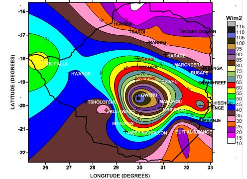
183 22
Anchor bolts ASTM F1554, Gr. 36 Wide flange beams ASTM A992, Fy = 50 ksi Misc. structural steel ASTM A36, Fy = 36 ksi
 STRUCTURAL NOTES MATERIAL STRENGTHS Structural Steel Reinforcing Steel Concrete Masonry Structural Lumber Anchor bolts ASTM F1554, Gr. 36 Wide flange beams ASTM A992, Fy = 50 ksi Misc. structural steel
OVERALL STRUCTURAL SYSTEM
 EXECUTIVE SUMMARY The at the Pittsburgh International Airport, PA, is a 275,000 square foot multi-use building located directly adjacent to the airport s landside terminal. The building consists of an
Table of Contents 2. Structural Systems.4 Foundations.4 Floor System...4 Columns..5 Lateral System...5
 WISCONSIN PLACE RESIDENTIAL TECHNICAL ASSIGNMENT 1 OCTOBER 5, 2007 KURT KRASAVAGE THE PENNSYLVANIA STATE UNIVERSITY STRUCTURAL OPTION FACULTY ADVISOR: DR. ALI MEMARI Table of Contents Table of Contents
Table 3. Detailed Comparison of Structural Provisions of IRC 2000 and 1997 NEHRP (Continued)
") 2000 IRC 1997 NEHRP Section Provision Section Provision Comments CHAPTER 3 BUILDING PLANNING R301 DESIGN CRITERIA R301.2.2 Seismic Provisions R301.2.2.1 Determination of Seismic Design Category R301.2.2.1.1
2000 IRC 1997 NEHRP Section Provision Section Provision Comments CHAPTER 3 BUILDING PLANNING R301 DESIGN CRITERIA R301.2.2 Seismic Provisions R301.2.2.1 Determination of Seismic Design Category R301.2.2.1.1
MASONRY WALL DATA: Wall Height = ft. Nominal Wall Thickness = 8.00 in. Depth to c.g. Steel, Wall = 3.81 in.
 TIME: 10:49 AM Page: 1 DESIGN METHOD : ACI 530-99: Working Stress Design MASONRY MATERIAL : Hollow Core Concrete Masonry Units MORTAR TYPE : Type S MORTAR MATERIAL : Portland Cement Lime Mortar BLOCK PLACEMENT
VOLUNTARY - EARTHQUAKE HAZARD REDUCTION IN EXISTING HILLSIDE BUILDINGS (Division 94 Added by Ord. No. 171,258, Eff. 8/30/96.)
") DIVISION 94 VOLUNTARY - EARTHQUAKE HAZARD REDUCTION IN EXISTING HILLSIDE BUILDINGS (Division 94 Added by Ord. No. 171,258, Eff. 8/30/96.) SEC. 91.9401. PURPOSE. (Amended by Ord. No. 172,592, Eff. 6/28/99,
DIVISION 94 VOLUNTARY - EARTHQUAKE HAZARD REDUCTION IN EXISTING HILLSIDE BUILDINGS (Division 94 Added by Ord. No. 171,258, Eff. 8/30/96.) SEC. 91.9401. PURPOSE. (Amended by Ord. No. 172,592, Eff. 6/28/99,
Visteon Village Corporate Center
 Visteon Village Corporate Center Van Buren Township, MI Technical Assignment #1 Jamison Morse Structural Option Advisor: Dr. Andres Lapage Jamison Morse Structural Option Visteon Village Center Advisor:
[TECHNICAL REPORT 3] Lateral System Analysis
![[TECHNICAL REPORT 3] Lateral System Analysis](/thumbs/96/126531717.jpg "[TECHNICAL REPORT 3] Lateral System Analysis") Science Center Research Park 3711 Market St. The Pennsylvania State University Department of Architectural Engineering Senior Thesis 2009-2010 Prepared by: November 30, 2009 [TECHNICAL REPORT 3] Lateral
Science Center Research Park 3711 Market St. The Pennsylvania State University Department of Architectural Engineering Senior Thesis 2009-2010 Prepared by: November 30, 2009 [TECHNICAL REPORT 3] Lateral
TECHNICAL REPORT 1. Structural Concepts / Structural Existing Conditions. Penn State Hershey Medical Center Children s Hospital. Hershey, Pennsylvania
 TECHNICAL REPORT 1 Structural Concepts / Structural Existing Conditions Penn State Hershey Medical Center Children s Hospital Matthew V Vandersall The Pennsylvania State University Architectural Engineering
MOUNTAIN STATE BLUE CROSS BLUE SHIELD HEADQUARTERS
 MOUNTAIN STATE BLUE CROSS BLUE SHIELD HEADQUARTERS PARKERSBURG, WEST VIRGINIA DOMINIC MANNO STRUCTURAL OPTION FACULTY CONSULTANT: DR. ANDRES LEPAGE Technical Report 3 11-21-08 TABLE OF CONTENTS TABLE OF
ICBO Evaluation Service, Inc Workman Mill Road, Whittier, California
 Reissued June 1, 2002 ICBO Evaluation Service, Inc. 5360 Workman Mill Road, Whittier, California 90601 www.icboes.org Filing Category: DESIGN Concrete DURISOL WALL FORMS FOR CONCRETE CONSTRUCTION DURISOL
Calculation of Wind Loads on Structures according to ASCE 7-10
 Calculation of Wind Loads on Structures according to ASCE 7-10 Permitted Procedures The design wind loads for buildings and other structures, including the Main Wind-Force Resisting System (MWFRS) and
REINFORCED CONCRETE MASONRY SECTION
 SECTION 04 22 02 - REINFORCED CONCRETE MASONRY PART 1 - GENERAL 1.1 RELATED DOCUMENTS A. Drawings and general provisions of Contract, including General and Supplementary Conditions and Division 01 Specification
Structural System. Design Criteria Fire Resistance Concrete designed for 2 HR rating (worst case) Geotechnical Report Allowable Bearing Capacity
 Geotechnical Report Allowable Bearing Capacity") System Codes and Criteria Design Codes and Standards The design code used is the Wisconsin Administrative Code along with the State of Wisconsin Department of Commerce-Safety & Buildings Chapters Comm
System Codes and Criteria Design Codes and Standards The design code used is the Wisconsin Administrative Code along with the State of Wisconsin Department of Commerce-Safety & Buildings Chapters Comm
DIVISION: METALS SECTION: STEEL DECKING REPORT HOLDER: EPIC METALS CORPORATION 11 TALBOT AVENUE RANKIN, PENNSYLVANIA 15104
 0 Most Widely Accepted and Trusted ICC ES Evaluation Report ICC ES 000 (800) 423 6587 (562) 699 0543 www.icc es.org ESR 2047 Reissued 07/207 This report is subject to renewal 07/209. DIVISION: 05 00 00
Masonry and Cold-Formed Steel Requirements
 PC UFC Briefing September 21-22, 2004 Masonry and Cold-Formed Steel Requirements David Stevens, ARA Masonry Requirements Composite Construction Masonry is often used in composite construction, such as
Jackson Crossing Located in Alexandria, VA. Technical Report 1 Michael Bologna
 Jackson Crossing Located in Alexandria, VA Technical Report 1 Michael Bologna Structural Option Advisor: Dr. Linda Hanagan September 11, 2015 Table of Contents Executive Summary.3 Introduction 4 Purpose..4
THE FORENSIC MEDICAL CENTER
 THE FORENSIC MEDICAL CENTER Image courtesy of Gaudreau, Inc. TECHNICAL REPORT #1 OCTOBER 5, 2007 KEENAN YOHE STRUCTURAL OPTION DR. MEMARI FACULTY ADVISOR EXECUTIVE SUMMARY Image courtesy of Gaudreau, Inc.
CHAPTER 3 BUILDINGS WITH WOOD FRAMED EXTERIOR WALLS 301 SCOPE
 CHAPTER 3 BUILDINGS WITH WOOD FRAMED EXTERIOR WALLS WOOD CHAPTER 3 301 SCOPE This chapter prescribes construction requirements for buildings where all exterior walls above the foundation are wood framed
Proposed Modification to the Florida Building Code
 Proposed Modification to the Florida Building Code Name: Joseph D. Belcher Address: 41 Oak Village Blvd. Homosassa, Fl 34446 E-mail: Joe@jdbcodeservices.com Phone: 352-450-2631 FAX: (813) 925-4152 Fax:
Danielle Shetler - Structural option Courtyard by Marriott Lancaster, PA
 Structural Analysis Overview: During the structural analysis of the in Lancaster, Pa, a redesign of the lateral and gravity system from masonry bearing and shear walls to a staggered truss system was performed.
Building Division Informational Handout
 CITY OF SAN JOSÉ, CALIFORNIA Building Division Informational Handout Conventional Light Frame Construction Design Provisions 2007 CBC Handout No. 2-21 Published: 1/1/08 Page 1 of 3 This document summarizes
ALLOWABLE STRESS DESIGN OF CONCRETE MASONRY LINTELS. TEK 17-1C Structural (2009) Related TEK: Uniform load. Triangular load. Concentrated loads
 Related TEK: Uniform load. Triangular load. Concentrated loads") An information series from the national authority on concrete masonry technology ALLOWABLE STRESS DESIGN OF CONCRETE MASONRY LINTELS TEK 17-1C Structural (2009) INTRODUCTION Lintels and beams are horizontal
An information series from the national authority on concrete masonry technology ALLOWABLE STRESS DESIGN OF CONCRETE MASONRY LINTELS TEK 17-1C Structural (2009) INTRODUCTION Lintels and beams are horizontal
REINFORCED ENGINEERING HANDBOOK CLAY AND CONCRETE MASONRY SEVENTH EDITION. John M. Hochwalt, PE, SE KPFF Consulting Engineers
 REINFORCED MASONRY ENGINEERING HANDBOOK CLAY AND CONCRETE MASONRY SEVENTH EDITION John M. Hochwalt, PE, SE KPFF Consulting Engineers James E. Amrhein Original Author Published by MASONRY INSTITUTE OF AMERICA
twenty three Masonry Construction 1 APPLIED ARCHITECTURAL STRUCTURES: DR. ANNE NICHOLS FALL 2018 lecture STRUCTURAL ANALYSIS AND SYSTEMS ARCH 631
 APPLIED ARCHITECTURAL STRUCTURES: STRUCTURAL ANALYSIS AND SYSTEMS DR. ANNE NICHOLS FALL 2018 lecture twenty three masonry construction Bright Football Complex www.tamu.edu Masonry Construction 1 Learning
Technical Report 1. Kingstowne Section 36A 5680 King Center Drive Kingstowne, VA James Chavanic. Structural Option. Advisor: Dr.
 Technical Report 1 Rendering provided by DCS Design 5680 King Center Drive Kingstowne, VA 22315 Advisor: Dr. Boothby September 17, 2012 TABLE OF CONTENTS Executive Summary 3 Building Introduction 4 Structural
Rutgers University Law School Building Addition and Renovation Camden, NJ
 Building Addition and Renovation Camden, NJ Technical Assignment 1 October 5, 2007 Nathan E. Reynolds Structural Option Senior Thesis The Pennsylvania State University Faculty Consultant: Professor M.
Hyatt Place North Shore. Pittsburgh, PA T. Technical Assignment #1. Kyle Tennant. Kyle Tenn. Structural (IP) [Type the document subtitle]
![Hyatt Place North Shore. Pittsburgh, PA T. Technical Assignment #1. Kyle Tennant. Kyle Tenn. Structural (IP) [Type the document subtitle]](/thumbs/85/92906985.jpg "Hyatt Place North Shore. Pittsburgh, PA T. Technical Assignment #1. Kyle Tennant. Kyle Tenn. Structural (IP) [Type the document subtitle]") Technical Assignment #1 Hyatt Place North Shore [Type the document subtitle] T Kyle Tenn Kyle Tenn Kyle Tennant Structural (IP) Dr. Ali Memari O c t o b e r 4 2 0 1 0 Table of Contents I. Executive Summary
Technical Assignment #1 Hyatt Place North Shore [Type the document subtitle] T Kyle Tenn Kyle Tenn Kyle Tennant Structural (IP) Dr. Ali Memari O c t o b e r 4 2 0 1 0 Table of Contents I. Executive Summary
twenty three Masonry Construction 1 APPLIED ARCHITECTURAL STRUCTURES: DR. ANNE NICHOLS SPRING 2018 lecture STRUCTURAL ANALYSIS AND SYSTEMS ARCH 631
 APPLIED ARCHITECTURAL STRUCTURES: STRUCTURAL ANALYSIS AND SYSTEMS DR. ANNE NICHOLS SPRING 2018 lecture twenty three masonry construction Bright Football Complex www.tamu.edu Masonry Construction 1 Learning
twenty three Masonry Construction 1 APPLIED ARCHITECTURAL STRUCTURES: DR. ANNE NICHOLS SPRING 2019 lecture STRUCTURAL ANALYSIS AND SYSTEMS ARCH 631
 APPLIED ARCHITECTURAL STRUCTURES: STRUCTURAL ANALYSIS AND SYSTEMS DR. ANNE NICHOLS SPRING 2019 lecture twenty three masonry construction Bright Football Complex www.tamu.edu Masonry Construction 1 Learning
Confined masonry. An illustrated guide for masons. This manual explains this technique. Confined masonry. RC frames. Columns first, walls after
 S D C Confined masonry An illustrated guide for masons This manual explains this technique RC frames Columns first, walls after Confined masonry Walls first, columns after 1. Site selection and form of
LIFE SCIENCES BUILDING STRUCTURAL CONCEPTS AND EXISTING CONDITIONS
 Structural Technical Report 1 LIFE SCIENCES BUILDING STRUCTURAL CONCEPTS AND EXISTING CONDITIONS Prepared for: Dr. Aly M. Said Dr. Thomas Boothby Professor Kevin Parfitt Dr. Charles D. Cox Prepared by:
Technical Report 1. Seneca Allegany Casino Hotel Addition. Salamanca, NY
 Technical Report 1 Seneca Allegany Casino Hotel Addition Salamanca, NY Nicholas Reed Structural Option Advisor: Prof. Parfitt Executive Summary The purpose of this technical report was to analyze the existing
CONFINED MASONRY CONSTRUCTION
 CONFINED MASONRY CONSTRUCTION Mario Rodriguez, Universidad Nacional Autonoma de Mexico, Mexico BACKGROUND Confined masonry construction consists of unreinforced masonry walls confined with reinforced concrete
TITEN HD Heavy Duty Screw Anchor for Concrete & Masonry
 TITEN HD Heavy Duty Screw Anchor for & Masonry The Titen HD is a patented, high-strength screw anchor for concrete and masonry. The self-undercutting, non-expansion characteristics of the Titen HD makes
William W. Wilkins Professional Building Columbus, Ohio
 William W. Wilkins Professional Building Columbus, Ohio Technical Assignment 1 October 5, 2006 Michelle Structural Option AE 481W Senior Thesis Faculty Advisor: Dr. Boothby Table of Contents Executive
Pennsylvania College Of Technology Dauphin Hall Williamsport, Pennsylvania
 Pennsylvania College Of Technology Dauphin Hall Williamsport, Pennsylvania Aubert Ndjolba Structural Option AE Senior Thesis- 2011 Thesis Advisor: Dr. Boothby Existing Building Overview Introduction Existing
Stone and Masonry Veneer
 Stone and Masonry Veneer R703.7 Stone and masonry veneer, general. Stone and masonry veneer shall be installed in accordance with this chapter, Table R703.4 and Figure R703.7. These veneers installed over
Technical Report #3: Lateral System Analysis. Executive Summary
 ERIC MUELLER STRUCTURAL OPTION ADVISOR DR. LEPAGE AE 481W DECEMBER 19, 2006 555 12 TH STREET OAKLAND, CALIFORNIA Technical Report #3: Lateral System Analysis Executive Summary 555 12 th Street is a 21
Structural Technical Report 1 Structural Concepts / Structural Existing Conditions Report
 Michael A. Troxell Structural Option Advisor: Professor Parfitt College of Business Administration Oct. 5, 2005 Structural Technical Report 1 Structural Concepts / Structural Existing Conditions Report
The Structural Redesign of Boyds Bear Country and its Related Systems. Boyds Bear Country, Pigeon Forge, Tennessee
 The Structural Redesign of Boyds Bear Country and its Related Systems Included in this Presentation: Background and Existing System Proposal Problem / Solution Structural System Redesigns Pre-cast Concrete
Office Building-G. Thesis Proposal. Carl Hubben. Structural Option. Advisor: Dr. Ali Memari
 Office Building-G Thesis Proposal Structural Option December 10, 2010 Table of Contents Executive Summary... 3 Introduction... 4 Gravity System...4 Lateral System:...6 Foundation System:...6 Problem Statement...
PLANNING DEPARTMENT 701 OCEAN STREET, 4 TH FLOOR, SANTA CRUZ, CA (831) FAX: (831)
 FAX: (831)") County of Santa Cruz PLANNING DEPARTMENT 701 OCEAN STREET, 4 TH FLOOR, SANTA CRUZ, CA 95060 (831) 4542580 FA: (831) 4542131 STATEMENT OF SPECIAL INSPECTIONS California Building Code 1704.3 Prior to issuance,
County of Santa Cruz PLANNING DEPARTMENT 701 OCEAN STREET, 4 TH FLOOR, SANTA CRUZ, CA 95060 (831) 4542580 FA: (831) 4542131 STATEMENT OF SPECIAL INSPECTIONS California Building Code 1704.3 Prior to issuance,
(800) (562) A Subsidiary of the International Code Council
 (562) A Subsidiary of the International Code Council") ICC-ES Evaluation Report ESR-2089 Reissued September 2014 This report is subject to renewal September 2016. www.icc-es.org (800) 423-6587 (562) 699-0543 A Subsidiary of the International Code Council DIVISION:
ICC-ES Evaluation Report ESR-2089 Reissued September 2014 This report is subject to renewal September 2016. www.icc-es.org (800) 423-6587 (562) 699-0543 A Subsidiary of the International Code Council DIVISION:
Supplemental Plan Correction Sheet for LA Residential Code Prescriptive Design (2011 LARC)
") Supplemental Plan Correction Sheet for LA Residential Code Prescriptive Design (2011 LARC) Plan Check Submittal Date: Plan Check #: Permit App.# Job Address: Applicant: Phone: ( ) P.C. Engineer: Phone:
Supplemental Plan Correction Sheet for LA Residential Code Prescriptive Design (2011 LARC) Plan Check Submittal Date: Plan Check #: Permit App.# Job Address: Applicant: Phone: ( ) P.C. Engineer: Phone:
1000 CONTINENTAL SQUARE
 1000 CONTINENTAL SQUARE KING OF PRUSSIA, PENNSYLVANIA Carter Davis Hayes Structural Option January 13, 2008 Advisor: Dr. Hanagan TABLE OF CONTENTS TABLE OF CONTENTS... 2 EXECUTIVE SUMMARY... 3 I. STRUCTURAL
Temecula Medical Center Temecula, CA
 Temecula Medical Center Temecula, CA Technical Assignment #2 Sean F. Beville The Pennsylvania State University Architectural Engineering Structural Option Senior Thesis Project Student Advisor: Thomas
Legacy report on the 1997 Uniform Building Code, the 2000 International Building Code and the 2000 International Residential Code
 LEGACY REPORT ER-4203 Reissued June 1, 2004 ICC Evaluation Service, Inc. www.icc-es.org Business/Regional Office # 5360 Workman Mill Road, Whittier, California 90601 # (562) 699-0543 Regional Office #
REINFORCING TABLES INSTALLATION MANUAL
 REINFORCING TABLES 201 REINFORCING TABLES Design Limitations Introduction The structural wall reinforcing and lintel design tables contained within the Appendix of NUDURA s Installation Manual have been
A REPORT ON THE EFFECTS OF WIND SPEED ON TIMBER CONSTRUCTION JOSHUA HUENEFELD. B.S., Kansas State University, 2012 A REPORT
 A REPORT ON THE EFFECTS OF WIND SPEED ON TIMBER CONSTRUCTION by JOSHUA HUENEFELD B.S., Kansas State University, 2012 A REPORT submitted in partial fulfillment of the requirements for the degree MASTER
SEAU 5 th Annual Education Conference 1. ASCE Concrete Provisions. Concrete Provisions. Concrete Strengths. Robert Pekelnicky, PE, SE
 ASCE 41-13 Concrete Provisions Robert Pekelnicky, PE, SE Principal, Degenkolb Engineers Chair, ASCE 41 Committee* *The view expressed represent those of the author, not the standard s committee as a whole.
Caitlin Ferrell Structural Option Dr. Boothby, AE Faculty Consultant. Erie Convention Center and Sheraton Hotel
 Caitlin Ferrell Structural Option Dr. Boothby, AE Faculty Consultant Erie Convention Center and Sheraton Hotel Erie, Pennsylvania Technical Report #2: Pro-Con Structural Study of Alternate Floor Systems
STATEMENT OF SPECIAL INSPECTION FORM
 Project Title: Permit #: Project Address: STATEMENT OF SPECIAL INSPECTION FORM This Statement of Special Inspections is submitted in fulfillment of the requirements of CBC Sections 1704 and 1705. Special
Eurocode 8 Timber and Masonry structures
 Brussels, 18-20 February 2008 Dissemination of information workshop 1 Eurocode 8 Timber and Masonry structures E C Carvalho, Chairman TC250/SC8 Brussels, 18-20 February 2008 Dissemination of information
Confined Masonry Buildings as Low- Cost Engineered Housing System
 Workshop on Performance Evaluation of Housing Units Confined Masonry Buildings as Low- Cost Engineered Housing System Dr. Vaibhav Singhal Department of Civil and Environmental Engineering Indian Institute
HIGH RISE CONDO SOHO, NEW YORK, NY
 HIGH RISE CONDO SOHO, NEW YORK, NY TECHNICAL ASSIGNMENT 1 October 5, 2006 Joseph The Pennsylvania State University Structural Option Faculty Advisor: Andres Lepage TABLE OF CONTENTS TABLE OF CONTENTS 2
Masonry Veneer - Chapter 6. Masonry Veneer Anchored Veneer
 Masonry Veneer - Chapter 6 Chapter 6 covers anchored and adhered veneer. Following are prescriptive requirements for areas with wind 110 mph Vertical support of masonry veneer Support: Noncombustible structural
Structural Performance of 8-inch NRG Concrete Masonry Units. Report Compiled for: Niagara Regional Group. Date: January 28, 2013
 Structural Performance of 8-inch NRG Concrete Masonry Units Report Compiled for: Niagara Regional Group Date: January 28, 2013 Report Prepared by: Dr. Shawn Gross, Associate Professor Dr. David Dinehart,
R Code and Commentary for 2012 NC Residential Code final 03/06/13
 R602.10 Code and Commentary for 2012 NC Residential Code final 03/06/13 Commentary italicized and printed in red 1. Section R602.10 -- provides charging language for two simplified bracing approaches (isolated
EXAMPLE STATEMENT OF SPECIAL INSPECTIONS (SSI)
") EXAMPLE STATEMENT OF SPECIAL INSPECTIONS (SSI) For this example let s consider a single-story retail shell building. The main structural walls consist of CMU construction with the front of the building
EXAMPLE STATEMENT OF SPECIAL INSPECTIONS (SSI) For this example let s consider a single-story retail shell building. The main structural walls consist of CMU construction with the front of the building
Lateral System Analysis and Confirmation Design November 15, 2004
 Jonathan Hill Structural AE Faculty Consultant Dr. Hanagan Lynde and Harry Bradley School of Technology & Trade Milwaukee, Wisconsin Lateral System Analysis and Confirmation Design November 15, 2004 Executive
Letter of Transmittal
 Letter of Transmittal November 17, 2014 Ali Said Structural Thesis Advisor The Pennsylvania State University aus59@psu.edu Dear Doctor Said, The following technical report fulfills the fourth Technical
Technical Assignment 3 December 3, 2007
 Technical Assignment 3 December 3, 2007 101 Eola Drive, Orlando, FL Justin Raducha Pennsylvania State University Faculty Advisor: M. Kevin Parfitt Table of Contents Table of Contents... 2 Executive Summary...
Structural Design Engineers 120 Montgomery Street, Suite 1410 San Francisco, California / Fax 415/
 120 Montgomery Street, Suite 1410 San Francisco, California 94104 415/781-1505 Fax 415/781-2718 sde@sdesf.com Rajendra Sahai, SE Principal John W. Laws, SE Principal Steven Lepisto, SE Principal STRUCTURAL
ALTERNATE DESIGN METHODOLOGY FOR UNREINFORCED MASONRY BUILDINGS
 INFORMATION BULLETIN / PUBLIC - BUILDING CODE REFERENCE NO.: LABC 8808 Effective: 01-01-2011 DOCUMENT NO. P/BC 2011-053 Revised: Previously Issued As: P/BC 2008-053 I. GENERAL ALTERNATE DESIGN METHODOLOGY
STRUCTURAL TECHNICAL REPORT 1
 Technical Report 1 Page 1 David Lee AE 481W Structural Option Advisor: Andres Lepage URS Office Building October 5, 2006 STRUCTURAL TECHNICAL REPORT 1 Structural Concepts / Structural Existing Conditions
INGHOUSE Page 1 of 48
 INGHOUSE Page 1 of 48 Lars Jensen P.E., S.E. Web: www.inghouse.net EMAIL: jensen@inghouse.net INGHOUSE Page 2 of 48 OBJECTIVES: DESIGN OPTIONS; WHY ENGINEERED DESIGN DEVELOP AN UNDERSTANDING OF MAGNITUDE
RCKW Kneewall Connectors
 This product is preferable to similar connectors because of a) easier installation, b) higher loads, c) lower installed cost, or a combination of these features. The Simpson Strong-Tie RCKW rigid connectors
Project. San Jose City College Physical Education Building. Prepared For. Prepared By PLACE IMAGE HERE. Ken Bauer, AIA Principal
 Project San Jose City College Physical Education Building PLACE IMAGE HERE Prepared For Ken Bauer, AIA Principal LPAS 2484 Natomas Park Drive Sacramento, CA 95833 916.443.0335 Prepared By Steve Ratchye,
HOLDOWN & STRAP SCHEDULE
 SHEAR WALL SCHEDULE STRUCTURAL DESIGN CRITERIA GOVERNING CODE SOIL BEARING PRESSURE HOLDOWN & STRAP SCHEDULE MARK SHEATHING SHEATH BOTH SIDES NAILS EDGE SPACING NOTES MARK SW 7/" OSB NO 8d " OC - A SW
Table of Contents.2. Introduction...3 Gravity Loading and Deflections..4. Existing Structural System..8
 WISCONSIN PLACE RESIDENTIAL TECHNICAL ASSIGNMENT 2 OCTOBER 29, 2007 KURT KRASAVAGE THE PENNSYLVANIA STATE UNIVERSITY STRUCTURAL OPTION FACULTY ADVISOR: DR. ALI MEMARI 1 Table of Contents Table of Contents.2
GARAGE MAIN FLOOR PLAN
 BUILDING CONTRACTOR/HOME OWNER TO REVIEW AND VERIFY ALL DIMENSIONS, SPECS, AND CONNECTIONS BEFORE CONSTRUCTION BEGINS. SHED TO BE BUILT AS PER IRC, UBC OR CURRENT LOCAL CODE To the best of my knowledge
VARIOUS TYPES OF SLABS
 VARIOUS TYPES OF SLABS 1 CHOICE OF TYPE OF SLAB FLOOR The choice of type of slab for a particular floor depends on many factors. Economy of construction is obviously an important consideration, but this
Structural Redesign Gravity System
 Redesign Gravity System Design Considerations A composite floor system was used for this design to maximize the efficiency of the material being used. This type of system requires less material and provides
Exterior Brick Masonry Veneer Supported by Metal Plate Connected Wood Trusses (MPCWT) Overview Revised 11/17/2016
 Overview Revised 11/17/2016") Exterior Brick Masonry Veneer Supported by Metal Plate Connected Wood Trusses (MPCWT) Overview Revised 11/17/2016 SBCA has been the voice of the structural building components industry since 1983, providing
Exterior Brick Masonry Veneer Supported by Metal Plate Connected Wood Trusses (MPCWT) Overview Revised 11/17/2016 SBCA has been the voice of the structural building components industry since 1983, providing
Statement of Special Inspections 2013 CBC
 BUILDIG & SAFET DIVISIO 2729 Prospect Park Drive Rancho Cordova, CA 95670 Phone: (916) 851-8760 Fax: (916) 851-8762 Statement of Special Inspections 2013 CBC PERMIT #: PROJECT ADDRESS: This Statement of
Supplemental Plan Correction Sheet for LA Residential Code Prescriptive Design (2014 LARC)
") Supplemental Plan Correction Sheet for LA Residential Code Prescriptive Design (2014 LARC) Plan Check Submittal Date: Plan Check #: Permit App.# Job Address: Applicant: Phone: ( ) Plan Check Engineer:
Supplemental Plan Correction Sheet for LA Residential Code Prescriptive Design (2014 LARC) Plan Check Submittal Date: Plan Check #: Permit App.# Job Address: Applicant: Phone: ( ) Plan Check Engineer:
ANCHOR BOLT ANGLE (AISC) ARCH. A. BOLT LBS. ARCHITECTURAL POUNDS B.O. DOUBLE ANGLE (AISC) BCI BOTTOM OF I-JOIST (BOISE CASCADE) LVL
 ARCH. A. BOLT LBS. ARCHITECTURAL POUNDS B.O. DOUBLE ANGLE (AISC) BCI BOTTOM OF I-JOIST (BOISE CASCADE) LVL") A. BOLT ANCHOR BOLT L ANGLE (AISC) ARCH. ARCHITECTURAL LBS. POUNDS B.O. BOTTOM OF LL DOUBLE ANGLE (AISC) BCI I-JOIST (BOISE CASCADE) LVL LAMINATED VENEER LUMBER BRG. BEARING MAX. MAXIMUM C CHANNEL (AISC)
A. BOLT ANCHOR BOLT L ANGLE (AISC) ARCH. ARCHITECTURAL LBS. POUNDS B.O. BOTTOM OF LL DOUBLE ANGLE (AISC) BCI I-JOIST (BOISE CASCADE) LVL LAMINATED VENEER LUMBER BRG. BEARING MAX. MAXIMUM C CHANNEL (AISC)
W. Mark McGinley March 3, 2016 ISEA MEETINGS 1
 J.B. SPEED SCHOOL OF ENGINEERING Design of s for Masonry Veneers W. Mark McGinley, Ph. D., PE FASTM MASONRY DAY Indianapolis March 3, 2016 Objectives Present a Brief Overview of: Masonry Veneer Wall systems
Project ULA 120D Snow-0 Seis-IV
 ULA Geometry Module Specification Sub-Array Configuration ULA Totals # Rows: 4 Column N-S Length (in): 6 # SubArrays: N-S Dim (in): 40 N-S Spacing (in): 0.25 # Columns: 5 Array E-W Dimension (in): 326
A Guide for the Interpretation of Structural Design Options for Residential Concrete Structures
 CFA Technical Note: 008-2010 A Guide for the Interpretation of Structural Design Options for Residential Concrete Structures CFA Technical This CFA Technical Note is intended to serve as a guide to assist
Check the strength of each type of member in the one story steel frame building below.
 CE 331, Summer 2015 nalysis of Steel Braced Frame Bldg 1 / 9 Check the strength of each type of member in the one story steel frame building below. 4 @ 8 ft B 20 f 1 2 3 @ 25 ft Side Elevation 3 4 Plan
*Corrected October 2005
 ESR-1056* Reissued December 1, 2004 This report is subject to re-examination in two years. ICC Evaluation Service, Inc. www.icc-es.org Business/Regional Office # 5360 Workman Mill Road, Whittier, California
Seismic Design and Behaviour of Confined Masonry Buildings
 IITG Workshop on Earthquake Resistance of Low-Cost Engineered Housing in North-East India Seismic Design and Behaviour of Confined Masonry Buildings Dr. Vaibhav Singhal Department of Civil and Environmental
Boyds Bear Country Pigeon Forge, TN
 Technical Report 1 Structural Concepts / Structural Existing Conditions Report Executive Summary:, located in Pigeon Forge, Tennessee, is designed as a multifunctional space and tourist attraction for
Executive Summary. Greg Kochalski. JW Marriott, Grand Rapids, MI
 Executive Summary JW Marriott, Grand Rapids, MI November 21, 2006 Greg Kochalski Structural Advisor: Boothby The JW Marriott is a 24 story hotel currently under construction in Grand Rapids, Michigan and
Statement of Special Inspection Requirements
 Statement of Special Inspection Requirements California Building Code Chapter 17 Construction plans shall include a statement of special inspection in accordance with CBC chapter 17. The statement of special
Considerations for Outof-Plane. Design
 Considerations for Outof-Plane Wall and Uplift Design WoodWorks Texas Workshops December, 2016 Overview Uplift Wall Design Wind Loads Wind loads acting on buildings are modeled as uniform surface loads.
North Shore at Canton Baltimore, MD Beau Menard Technical Report 1
 North Shore at Canton Baltimore, MD Beau Menard Technical Report 1 Structural Schneider 10/05/05 Structural Concepts Executive Summary North Shore at Canton is a 4 story town home and parking garage structure
Technical Report #1. Matthew R Peyton
 Technical Report #1 This Document is Technical Report #1 for 5th year senior thesis in the Architectural Engineering Departments at The Pennsylvania State University. This Report will include structural
Structural Tests and Special Inspections Form. Inspection of Fabricators (1704.2)
") Inspection of Fabricators (1704.2) Furnish inspection reports (1704.2.1) - Fabricators that have not been approved Provide a Certificate of Compliance (1704.2.2) - Approved Fabricators Steel Construction
Inspection of Fabricators (1704.2) Furnish inspection reports (1704.2.1) - Fabricators that have not been approved Provide a Certificate of Compliance (1704.2.2) - Approved Fabricators Steel Construction
Alexis Pacella Structural Option Dr. Schneider Lexington II, Washington D.C. Technical Report #3 November 21,
 1 Executive Summary: Lateral System Analysis and Confirmation Design is an depth look at the lateral system of Lexington II and the loads of which it must carry. The structural system of Lexington II is
Simplified Building Schematic for Typical Floor (Levels 9 through 22):
:") Introduction to Structural System Simplified Building Schematic for Typical Floor (Levels 9 through 22): Key: - Tower Columns - Tower Shear Walls - Parking Garage Columns - Parking Garage Shear Walls Solid
Introduction to Structural System Simplified Building Schematic for Typical Floor (Levels 9 through 22): Key: - Tower Columns - Tower Shear Walls - Parking Garage Columns - Parking Garage Shear Walls Solid
30 X 40 POLE BARN 12 HIGH SIDE WALLS 2-12 WIDE X 10 HIGH SECTIONAL GARAGE DOORS OPTIONAL WINDOWS DETAILS INCLUDED
 30 X 40 POLE BARN 12 HIGH SIDE WALLS 2-12 WIDE X 10 HIGH SECTIONAL GARAGE DOORS OPTIONAL WINDOWS DETAILS INCLUDED 3 ENTRY DOOR METAL ROOF METAL SIDING GABLE ROOF, 4/12 PITCH INDEX PAGE DESCRIPTION 1 FRONT
The following are details of the code requirements of the 2015 International Residential Code for single-story decks.
 The following are details of the code requirements of the 2015 International Residential Code for single-story decks. The 2015 International Residential Code Section R507 contains additional information
Tables with Allowable ASD Seismic Values For Design at R = 6.5. Special Moment Frame MF1-12
 Tables with Allowable ASD Seismic Values For Design at R = 6.5 Special Moment Frame MF1-12 Hardy Frames, Inc manufactures and markets pre-fabricated shear wall systems. We have been the innovative leader
School of Engineering and Applied Science Building Miami University, Oxford, OH Technical Assignment 3 December 3, 2007
 School of Engineering and Applied Science Building Miami University, Oxford, OH Technical Assignment 3 December 3, 2007 Jonathan Kirk AE 481W Senior Thesis The Pennsylvania State University Faculty Advisor:
Brent Ellmann Structural Option 200 Minuteman Park, Andover, MA Structural Consultant: Dr. Hanagan
 Structural Design: Goals: The original design of 200 Minuteman Drive was dictated largely by Brickstone Properties, the building s owner. The new design of 200 Minuteman Drive, with additional floors,