Product Catalogue Telecommunication Hardware
|
|
|
- Angel Jacobs
- 5 years ago
- Views:
Transcription


1 Product Catalogue Telecommunication Hardware
2 Content Above-Surface Hardware Guy Clamp, Suspension Clamp and Suspension Pulley 4-5 Utility Pole Top Cover 6 Screw Anchor and Turnbuckle 7 Wall Hook, Guy Hook, Thimble, and Wire Clamp 8 Crossarm with Hooks and Accessories 9 Cable Protection Channels Cable Marker 11 Below-Surface Hardware Cable Support Rail, Cable Support, and Sleeve Support Tray Shaft Ladder and Ladder Guard Dirt Collecting Tray and Tool Yoke Wall Bushing 21 Spacer and Belt Clamp 22 Earth Rod 23 Wire clamp Thimble Cable marker Turnbuckle Screw anchor
3 Above-Surface Hardware Above-Surface Hardware Utility pole top cover Guy hook Crossarm with hooks Guy clamp Wall hook Suspension pulley Pole Saddle clamp Cable Protection Channels Ground level (Schematic representation)
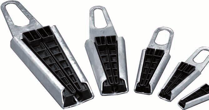
4 Above-Surface Hardware Cable Suspension Guy clamp Convenient and reliable suspension of installation cables on poles and building walls Steel housing with two tapered plastic clamping jaws, clamping down under tensile stress Suspension e.g. on guy hooks or crossarm hooks Temperature range: -30 C to +60 C PA6 GF30 DIN to 540 Meas to 150 Meas. 3 Guy hook Open clamping jaws Meas. 1 Cable Cable Clamping the cable under tensile stress Pole Housing Clamping jaws (PA6 GF30) Size for Permitted Weight L x W jaw eyelet cable ø tensile load in kg in mm Meas. 1 Meas. 2 Meas. 3 in mm in kn in mm in mm in mm SS 5.5 to 9.5 2, x 48 min S 8.5 to , x 67 min M 12.5 to , x 80 min L 16.5 to 24 7, x 116 min XL 22.5 to x 150 min
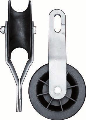
5 Above-Surface Hardware Cable Suspension Suspension Clamp PS 510 Suspension of messenger cables Clamping the messenger with two plastic clamping jaws Stainless steel hook (flexible) for suspending the suspension clamp from the support hook Stainless steel hook PA6 GF30 Clamping jaws Stainless Steel Clamping diameter A Clamping diameter B Cable Messenger Nut and bolt made of stainless steel Suspension clamp Clamping diameter in mm A B PS to 7 8 to Suspension Pulley Suspension pulley for mounting, guiding and bearing cables used in above-ground lines Consisting of two hot-dipped steel plates holding pivoting castor made of PA6-GF30 Temperature range: -40 C to +60 C PA6 GF30 Cable Size for cable ø in mm Permitted tensile load in kn Weight in kg 150/ to / to / to Pole 5
6 Above-Surface Hardware Pole and Cable Suspension Pole Suspension (Pole with Anchor) Spigot Cover Wall hook Wire cable Wire clamp Wire sleeve (injury protection) Wire cable Wire clamp Thimble Turnbuckle (includes eyebolt) Pole Screw anchor Ground level 1.5 m 1.5 m (Schematic representation) Screw anchor Spigot Cover Spigot Cover Covering the slanted tops of utility poles Comes with 6 nails (3x per slope) Nail Weight in kg Pieces Pole 6
7 Above-Surface Hardware Pole and Cable Suspension Screw anchor Securing and reinforcing poles Installation by auguring into the ground, with the longitudinal axes of the helical anchor pointing in the direction of the anchor cable 2000 Pinhole ø Screw anchor Weight in kg M Turnbuckle Suspension of anchor cable or messenger Turnbuckle with 2x eyebolts Turnbuckle with 1x eyebolt 100 Right-hand thread Left-hand thread Pinhole ø 5 Turnbuckle M 16 with 2x eyebolt M 16 with 1x eyebolt
8 Above-Surface Hardware Pole and Cable Suspension Wall Hook Wall hook with wood thread For screwing into masonry or wooden pole ø 12 Wall Weight in kg Pieces Pole Guy Hook For suspension points under tensile stress e.g. overhead cable Comes with 2x washer and hexagon nut 64 Weight in kg ø Pole 200 Thimble (Thimble 70 s) 100 Loop shaping and protection of wire cables Thimble Thimble 70 s R = Wire Clamp (DIN 48335) For connecting wire ropes for rope ø in mm 7.5 to Washer 18 (DIN 126) Wire rope Hexagon nut M16 (DIN 555) Supporting ring C (DIN 48335) Clamping plate A (DIN 48335) Clamping ear B (DIN 48335) 8
9 Above-Surface Hardware Crossarms and Accessories Crossarm (A 550) with Hooks Installation on wooden pole for parallel line routing of up to four lines Complete with installation material Crossarm Mounting bracket Arm clip Crossarm Hooks for crossarm Pole 210 / 240 / 270 Pole 105 / 120 / 140 ø Hooks for crossarm incl. hexagon nut (M16) ø 130 ø 170 ø 200 Arm clip with hexagon nuts and ring washers (M16) Mounting bracket (DIN 48322) R = Crossarm Length 550 mm Crossarm accessories Mounting bracket Hooks for crossarm Arm clip Arm clip Arm clip
10 Above-Surface Hardware Cable Protection Cable Protection Channel 1700 Protection of cable mounted on walls or poles against external damages Overlapping assembly if several cable protection channels are used Installation of the saddle clamp on curved or level surface (e.g. pole or wall) and additionally with clamp tie plate for mounting on uneven surfaces Clamp Guy clamp Cable protection channel (cross section) Distribution point 56 Saddle clamp Cable max ø 25 Saddle clamp Cable Pole 67 max. ø 25 Saddle clamp Wall Pole Length Pieces 1700 mm Cable protection channel Cleat Pieces Upper part Bottom part min. 10 cm Ground level (Schematic representation) 10
 Without")
 Cable Clamp A = 45 B = 88.5 C = 65 Wall Model A (length 3000 mm) 84.0001.00.00 B (length 3000 mm) 84.")

 Comes with anchoring and connecting piece, plastic head, locking bolt, and labelling plate.")

11 Above-Surface Hardware Cable Protection and Marker Cable Protection Channel Protection of cable mounted on walls or poles against external damages Installation with suitable fixing clamp model (3 pieces for each cable protection channels) Without sleeve nut (not overlapping) A = 90 B = 145 C = 110 galvanized A = 33 B = 65 C = 50 A = 26 B = 60 C = 40 Cable protection channel (cross section) Cable Clamp A = 45 B = 88.5 C = 65 Wall Model A (length 3000 mm) B (length 3000 mm) C (length 3000 mm) Clamp for model A B C Cable Marker 82 Detection of underground cable systems in undeveloped locations without fixed points for calibrating the cable system Galvanised anchoring and connector to the ground connection with anchoring nails (3x) Captive plastic head (marking with labelling plate possible) Comes with anchoring and connecting piece, plastic head, locking bolt, and labelling plate. Labelling plate HOT- Ground level Cable marker Complete cable marker Plastic head , Plastic head Anchoring nail Length in mm Pieces Ground level Anchoring and connecting piece 350 or
 Cable support Cable vault (Schematic representation)")
12 Below-Surface Hardware Above-Surface Hardware Cable support rail (set in concrete) Shaft ladder (straight) Sleeve support tray Cable support rail (bolted down) Cable support Cable vault (Schematic representation) Spacer
 670 7 59.0111.00.")
13 Below-Surface Hardware Cable Vault and Junction Box Cable Support Rail for Setting in Concrete Cable supports and cable support straps are fastened using the punched slots with a grid dimension of 75 In the case of prefab concrete shafts, the cable support rail is set flush into the concrete at predefined intervals Length in mm Number of bolts (ø 10 x 75 mm) to Shaft wall concrete C20/25 Special lengths available upon request. Cable Support Rail Cable supports and cable support straps are fastened using the punched slots with a grid dimension of 75 Post-construction installation on the shaft wall at predefined intervals, using heavy duty anchors Comes with heavy duty anchor M8 x 65 Standard FTZ TV Heavy duty anchor 75 for cable vault inside depth in m Nominal size in mm Permitted load capacity in kg Special lengths available upon request. 1 Concrete C20/ to Shaft wall concrete C20/25 13

")


 with cantilever")


14 Below-Surface Hardware Cable Vault and Junction Box Cable Support 80 System-compatible storage of cables and utility lines Permitted load capacity (distributed load) in combination with cable support rail 1000 N (+750N transient) PA6 GF Mounting into the cable support rail 80/20 80/30 Lock cotter 80/ /60 Lock cotter Cable support rail (KHS) Adjusting Position Horizontal locked standard position of the console will pivot by 45 each after lock cotter is removed. 45 Standard Position 45 Cable support (80/20) with cantilever bracket (hole Ø 13 mm) for wall mounting or mounting in cast-in channel Cable support for cable support rail Cable support for wall mounting / cast-in channel Size Length in mm Weight in kg 80/ / / / Size Length in mm Weight in kg 80/ / / /
 Cantilever brackets including cotter pin (DIN 11024) for cable support rails 95/40 Stainless Steel Adjusting Position Infinitely variable sleeve support tray Cotter pin 95/60")

15 Below-Surface Hardware Cable Vault and Junction Box Sleeve Support Tray 95 and Cantilever Bracket Placement of sleeves in cable vaults Load per unit area (95/60) 400 N min. (1000 N transient) Cantilever brackets including cotter pin (DIN 11024) for cable support rails 95/40 Stainless Steel Adjusting Position Infinitely variable sleeve support tray Cotter pin 95/60 Cantilever bracket Cable support rail 760 to 1100 mm Sleeve joint e.g. with tightening straps Complete sleeve support tray Sleeve support tray Number of trays Number of cantilever brackets Supporting surface width x depth in mm to 1100 x / to 1100 x / to 1100 x Cantilever bracket (includes cotter pin DIN 11024) for cable support rail Size Installation depth in mm (about)


16 Below-Surface Hardware Cable Vault and Junction Box Extendible Shaft Ladder Two-piece (upper and lower ladder section), attached to ladder hoop Shaft ladder 180/55 Size Shaft ladder: 180/ Shaft ladder: 180/ Shaft ladder: 210/ Upper / lower ladder Steps Lower ladder Lower ladder Upper ladder Upper ladder Manhole ring height 55 cm Upper ladder Ladder hoop Mounting and fixing the lower ladder to the ladder hoop Clear shaft depth 180 cm Lower ladder 68 to Shaft wall Ladder Hoop Extendible for Shaft Ladder 495 Bracket for hooking the lower ladder Ladder hoop ø includes 2x bolt M12x70 DIN 571, washer 13 DIN 9021 and plugs


 59.2164.02.00 59.2164.01.")
17 Below-Surface Hardware Cable Vault and Junction Box Large Shaft Ladder Climbing aid Rungs Stringer length in mm Shaft ladder 10 rungs Wall anchor Mounting and Accessories for Straight Shaft Ladder Mounting shaft ladder to shaft wall and floor Floor mounting Shaft wall Article Wall anchor complete (includes 4x washer A13 DIN125, 2x washer 13 DIN9021, 2x bolt M12x60 DIN933, 2x nut M12 DIN934, 2x screw 12x70 DIN571, 2x plug S14) Complete floor mounting set (includes 4x washer 13 DIN125, 4x screw 12x70 DIN571, 4x plug S14) Wall anchor Floor mounting Climbing aid with support handle retraction (5 rungs or more) Climbing aid 17
 Shaft ladder Article Mobile")
 Valve (Stowing and securing ladder) Clamping lever for adjusting angle (5 to 15")

18 Below-Surface Hardware Cable Vault and Junction Box Mobile Ladder Guard (Adjustable) Ladder guard for vertical insertion of standard store-bought ladders (width: 350 bis 385 mm, stringer depth 70 mm) Shaft ladder Article Mobile ladder guard min. 1 m Locking pin max. 300 Handle Adapter (Suspension bracket) Valve (Stowing and securing ladder) Clamping lever for adjusting angle (5 to 15 ) 5 m max. Adapter for Mobile Ladder Guard Suspension bracket for holding the mobile ladder guard Adapter for Mobile Ladder Guard Suspension bracket, includes 2x hexagon bolt M10x70 DIN 571, 2x washer 10,5 DIN 125, 2x plug S Hooking the mobile ladder guard into the suspension bracket Shaft wall 18


 625 Support recess Article Weight in kg Dirt collecting tray 86 with 4 cantilever")

 695 (width of tool yoke A) 677 (width of tool yoke C) 280 Cable vault (140 x 70")
19 Below-Surface Hardware Cable Vault and Junction Box Dirt Collecting Tray 86 Protects junction box structures against dirt and rainwater Held by cantilever brackets that hook into the dedicated support recesses in the shaft wall, or else by tool yokes High rigidity, with spillover of grey water during removal being prevented by ribbed design Cantilever bracket PP GF 735 (width of tool yoke B) 73 Cantilever brackets PP GF Junction box (70 x 40 cm) 625 Support recess Article Weight in kg Dirt collecting tray 86 with 4 cantilever brackets Dirt Collecting Tray 87 Protects cable vault structures against dirt and rainwater Hooks into the dedicated support recesses in the shaft wall or held by tool yokes 735 (width of tool yoke B) 695 (width of tool yoke A) 677 (width of tool yoke C) 280 Cable vault (140 x 70 cm) Support recess 585 Article Weight in kg Dirt collecting tray
20 Below-Surface Hardware Cable Vault and Junction Box Tool Yoke Storage and lifting aid for dirt collecting trays Dirt collecting tray Model A Model B Model C Support Model D Cable vault or junction box (AzK) 737 Model AzK (junction box) Model straight 430 Tool Yoke Length in mm Model A Model B Model C Model D Model E Model AzK Model straight
21 Below-Surface Hardware Bushings Wall Bushing MD 1 and MD 2 Wall thickness 480 max. Insulation coat Gas- and water-proof channelling of cables through masonry Heat-shrinkable polyethylene hose with integrated support spiral Adhesive exterior coating for dense bonding with concrete, cement or mortar Resistant against aliphatic and hydroaromatic hydrocarbons, ground salts and soil alkalines Overhanging shrinkable hose-ends with hot-melt adhesive inner lining Three drill hole calibres as counter support (2x fixed to MD) for the cement mortar to be inserted If the wall thickness exceeds 480 mm, several wall bushings may be gathered into one. Wall Marker ring Cable clip Cement mortar Drill hole calibre min. 80 Ground min. 80 about 800 fixed fixed flexible Wall exterior Pipe / cable without support spiral shrunk-to-fit MD for wall thickness >480 mm Wall bushing for cable/ pipe ø in mm max. wall thickness in mm Minimum drill hole ø in mm Pieces MD 1 8 to MD 2 10 to MD 50-3F (3x) 8 to 14 (1x) KKR DN Sealant max. ø 26 Sealant made of non-setting sealing compound for inserting two cables into an MD 2 wall bushing MD 2 Cable 1 Cable 2 for wall bushing Number required MD Sealant 21


 Pieces 110/4 4x DN110 50 59.1401.00.00 110/6 6x DN110 50 59.1402.00.00 110/8 8x DN110 50 59.")
 ø 115 (DN110) 22")
22 Cable Ducts and Protective Cable Conduits Below-Surface Hardware Spacer HDPE Facilitates setting up pipe assemblies and ensures a constant gap of 30 mm between the pipes Prevents lateral protrusion of pipes during future excavating work next to the pipe assembly Horizontally or vertically parallel installation of any number of pipes High rigidity for secure routing even with narrow-curving radii Separation option for Spacer 50/10 in 2- or 3-strain pipe lines Recommended interval between spacers 1.5 m 110/4 110/6 110/ ø /3-110/2 50/ Installation example (plan view) 1.5 m ø /8 Separating line Spacer for cable duct pipe (KKR) Pieces 110/4 4x DN /6 6x DN /8 8x DN /3-110/2 3x DN50 + 2x DN /10 10x DN /6 DN110 Belt Clamp for Cable Duct Half-Pipe Sleeve 20 Stainless Steel M6x20 DIN933 for DN DN Cable duct half-pipe Belt clamp Cable duct half-pipe sleeve ø 53,5 (DN50) ø 115 (DN110) 22
23 Below-Surface Hardware Earth Rod Ground level Earth Rod and Pipe Earth Rod For installing earthing systems Optimised earthing to meet seasonal weather fluctuations through autonomously constant earth electrode resistance Earthing band inserted from above Driving stud for earth rod Ø 26.9 x to 60 cm 108 Earthing band 30 x 3.5 mm laterally inserted Pipe earth rod Earth rod connecting clamp Round earth ø 8 Earth rod ø 25 Earth rod ø Separate parts Earth rod tip Earth rod Earth rod tip (strike point) Earth rod terminal clamp (for connecting earth rod and steel bands or rods) Pipe earth rod Pipe earth rod tip (driving point) Pipe earth rod terminal clamp (upon request) (upon request) Driving head for manual driving for earth rod May be extended by coupling for pipe earth rod (upon request) 23
24 Contact Berthold Sichert GmbH Kitzingstr. 1-5 D Berlin Key Account Consulting Tel.: Fax.: Caroline von Papen All of the information provided here is correct and reliable to the best of our knowledge. The information does not, however, warrant any characteristics. Any user of our products is solely responsible to assess whether our products suit the user's intended purpose. Our product warranty is exclusively limited to the terms and conditions of sale, delivery and payment. In no case will we be liable for incidental, indirect damage and collateral damage resulting from the same. Status: 9. October 2012, 3:17 PM/nee.
CONSTRUCTION SPECIFICATION FOR POLE ERECTION
 ONTARIO PROVINCIAL STANDARD SPECIFICATION METRIC OPSS 615 SEPTEMBER 1993 CONSTRUCTION SPECIFICATION FOR POLE ERECTION 615.01 SCOPE 615.02 REFERENCES 615.05 MATERIALS TABLE OF CONTENTS 615.05.01 Concrete.02
SECTION HANGERS AND SUPPORTS FOR PLUMBING PIPING AND EQUIPMENT. A. ASME B31.1 (American Society of Mechanical Engineers) - Power Piping
 - Power Piping") SECTION 22 05 29 HANGERS AND SUPPORTS FOR PLUMBING PIPING AND EQUIPMENT PART 1 - GENERAL 1.1 SUMMARY A. Section includes pipe and equipment supports, hangers, anchors, bases sleeves and the sealing of
SECTION 22 05 29 HANGERS AND SUPPORTS FOR PLUMBING PIPING AND EQUIPMENT PART 1 - GENERAL 1.1 SUMMARY A. Section includes pipe and equipment supports, hangers, anchors, bases sleeves and the sealing of
 Cutouts and Fuse Links Equipment to protect against faults and over-current conditions on power distribution systems. Open-Type Cutouts Linkbreak Cutouts Loadbreak Cutouts Cutout-Arrester Combinations
SECTION HANGERS AND SUPPORTS FOR HVAC PIPING AND EQUIPMENT
 SECTION 23 05 29 HANGERS AND SUPPORTS FOR HVAC PIPING AND EQUIPMENT PART 1 - GENERAL 1.1 SUMMARY A. Section includes pipe and equipment supports, hangers, anchors, bases sleeves and the sealing of work
SECTION HANGERS AND SUPPORTS FOR PLUMBING
 SECTION 22 05 29 HANGERS AND SUPPORTS FOR PLUMBING PART 1 - GENERAL 1.1 RELATED DOCUMENTS A. Drawings and general provisions of the Contract, including General and Supplementary Conditions and Division
NORTH HARRIS COUNTY REGIONAL WATER AUTHORITY PIPE HANGERS, Section PIPE HANGERS, SUPPORTS, AND RESTRAINTS
 PART 1 GENERAL 1.01 SUMMARY Section 15140 PIPE HANGERS, This Section includes the furnishing and subsequent installation of: A. Pipe and equipment hangers, supports, and associated anchors B. Equipment
B. American Society for Testing and Materials: 1. ASTM F708 - Standard Practice for Design and Installation of Rigid Pipe Hangers.
 SECTION 230529 - HANGERS AND SUPPORTS PART 1 GENERAL 1.1 SUMMARY A. Section Includes: 1. Pipe hangers and supports. 2. Hanger rods. 3. Inserts. 4. Flashing. 5. Sleeves. 6. Mechanical sleeve seals. 7. Firestopping
Modular Scaffolding MEKA 48
 Modular Scaffolding MEKA 48 MODULAR SCAFFOLDING MEKA 48 MODULAR SCAFFOLDING The Modular Scaffolding MEKA 48 is designed to adapt to the most complex scaffold structures. Its versatility offers a wide range
1. Hangers and supports for electrical equipment and systems.
 PART 1 - GENERAL... 1 1.1 RELATED DOCUMENTS... 1 1.2 SUMMARY... 1 1.3 DEFINITIONS... 1 1.4 PERFORMANCE REQUIREMENTS... 1 1.5 SUBMITTALS... 2 1.6 QUALITY ASSURANCE... 2 1.7 COORDINATION... 2 PART 2 - PRODUCTS...
Nortrax Section David Manchester Road, Ottawa NON-STRUCTURAL METAL FRAMING 16 May 2014 Page 1
 16 May 2014 Page 1 PART 1 GENERAL 1.1 DESCRIPTION This section specifies steel studs wall systems, shaft wall systems, ceiling or soffit suspended or furred framing, wall furring, fasteners, and accessories
distribution Modular Scaffolding
 Modular Scaffolding Modular scaffolding PDM Universal scaffolding system plettac-pl PDM Application A characteristic feature of plettac PDM system is the use of wedge joint which provides quick and safe
CONSTRUCTION SPECIFICATION FOR FOOTINGS AND PADS FOR ELECTRICAL EQUIPMENT
 ONTARIO PROVINCIAL STANDARD SPECIFICATION OPSS.MUNI 616 APRIL 2018 CONSTRUCTION SPECIFICATION FOR FOOTINGS AND PADS FOR ELECTRICAL EQUIPMENT TABLE OF CONTENTS 616.01 SCOPE 616.02 REFERENCES 616.03 DEFINITIONS
SECTION HANGERS AND SUPPORTS FOR ELECTRICAL SYSTEMS
 SECTION 26 05 29 HANGERS AND SUPPORTS FOR ELECTRICAL SYSTEMS PART 1 GENERAL 1.1 DESCRIPTION A. Scope: 1. CONTRACTOR shall provide all labor, materials, equipment, and incidentals as shown, specified, and
TRITEC light Steel Panel Formwork
 TRITEC light Steel Panel Formwork Perfection made in Germany Various practical illustrations of TRITEC Panel Combinations Guaranteed the largest possible range of sizes with the least possible amount of
CONSTRUCTION SPECIFICATION FOR FOOTINGS AND PADS FOR ELECTRICAL EQUIPMENT
 ONTARIO PROVINCIAL STANDARD SPECIFICATION METRIC OPSS 616 NOVEMBER 2008 CONSTRUCTION SPECIFICATION FOR FOOTINGS AND PADS FOR ELECTRICAL EQUIPMENT TABLE OF CONTENTS 616.01 SCOPE 616.02 REFERENCES 616.03
ELECTRICAL CONTRACTORS THE UNIVERSITY OF TENNESSEE KNOXVILLE, TENNESSEE SECTION PAGE 1 SECTION SUPPORTING DEVICES
 KNOXVILLE, TENNESSEE SECTION 26 05 29 PAGE 1 PART 1 - GENERAL: 1.01 DESCRIPTION OF WORK: SECTION 26 05 29 A. Extent of supports, anchors, sleeves and seals is indicated by drawings and schedules and/or
SECTION VIBRATION AND SEISMIC CONTROLS FOR ELECTRICAL SYSTEMS
 SECTION 260548 - VIBRATION AND SEISMIC CONTROLS FOR ELECTRICAL SYSTEMS PART 1 - GENERAL 1.1 SUMMARY A. Section includes: 1. Isolation pads. 2. Spring isolators. 3. Restrained spring isolators. 4. Channel
1.2 ACTION AND INFORMATIONAL SUBMITTALS.1 Provide submittals in accordance with Section Submittal Procedures.
 BID OPPORTUNITY NO. 253-2011 PAGE 1 OF 7 PART 1 GENERAL 1.1 REFERENCES.1 American Society of Mechanical Engineers (ASME).1 ASME B31.1, Power Piping, B31.3 Process Piping, B31.9 Building Services Piping..2
Modular Scaffold MEKA 48
 Modular Scaffold MEKA 48 Imperial units NA MODULAR SCAFFOLD MEKA 48 MODULAR SCAFFOLD The Modular Scaffold MEKA 48 is designed to adapt to the most complex scaffold structures. Its versatility offers a
3. Intermediate metal conduit (IMC). 4. Electric metallic tubing (EMT). 5. Flexible metal conduit (FLEX). 6. Polyvinyl chloride conduit (PVC).
. 4. Electric metallic tubing (EMT). 5. Flexible metal conduit (FLEX). 6. Polyvinyl chloride conduit (PVC).") SECTION 16111 CONDUITS PART 1 - GENERAL 1.01 DESCRIPTION A. General: Provide conduits, complete, as shown, specified or required per Contract Documents. Principal items include: 1. Rigid aluminum conduit.
SECTION 16111 CONDUITS PART 1 - GENERAL 1.01 DESCRIPTION A. General: Provide conduits, complete, as shown, specified or required per Contract Documents. Principal items include: 1. Rigid aluminum conduit.
GLENWOOD PLACE 2 MAR 2015
 PART 1 - GENERAL 1.01 SUMMARY: SECTION 16110 RACEWAYS A. Description: 1. Provide continuous conduit systems - beginning at the service point, to all distribution equipment and to every outlet and piece
SECTION VIBRATION AND SEISMIC CONTROLS FOR ELECTRICAL SYSTEMS
 PART 1 - GENERAL 1.1 RELATED DOCUMENTS A. Drawings and general provisions of the Contract, including General and Supplementary Conditions, apply to this Section. 1.2 SUMMARY A. This Section includes the
SECTION HANGERS AND SUPPORTS FOR PLUMBING PIPING AND EQUIPMENT
 Page 220529-1 SECTION 220529 - PART 1 - GENERAL 1.1 RELATED DOCUMENTS A. Drawings and general provisions of the Contract, including General and Supplementary Conditions and Division 01 Specification Sections,
1470 Dale Court Austell, GA Phone: Fax:
 1470 Dale Court Austell, GA 30168 Phone: 404-351-2202 Fax: 404-351-2203 LC METALS, INC. PRODUCT INDEX Page # STUD GUARDS...3 FHA STRAPS...3 BOCA PLATES (Nail Plates)...4 PLUMBERS TAPE (Banding Iron)...4
RAPID Column Formwork For the highest requirements on concrete surfaces and edge formation. Product Brochure Issue 10/2017
 For the highest requirements on concrete surfaces and edge formation Product Brochure Issue 10/2017 Content System advantages 5 For the highest requirements on concrete surfaces and edge formation 8 For
SEISMIC RESTRAINT SYSTEM
 1. GENERAL 1.1. Description: SECTION 16012 SEISMIC RESTRAINT SYSTEM 1.1.1. This specification covers design and installation of seismic bracing and anchorage required for conduit, cable tray, bus duct,
Stainless steel. 1.6 Stainless steel IP 69 K. Premium Panel, protection category IP 69K
 T Premium Panel, protection category IP 69K IP 69 K.6 H H H Optionally with or without keyboard housing Resistant to high-pressure cleaning (protection category IP 69K). The seal lies between two surfaces
CONSTRUCTION SPECIFICATION FOR INSTALLATION OF POLES
 ONTARIO PROVINCIAL STANDARD SPECIFICATION METRIC OPSS.PROV 615 April 2017 CONSTRUCTION SPECIFICATION FOR INSTALLATION OF POLES TABLE OF CONTENTS 615.01 SCOPE 615.02 REFERENCES 615.03 DEFINITIONS - Not
Planning and installation instructions
 Planning and installation instructions Stofix Oy Ahlmaninkatu 2 E 40100 Jyväskylä Finland stofixgroup@stofix.com www.stofix.com 2 PLANNING AND INSTALLATION INSTRUCTIONS... 1 1 General... 3 2 Project Design...
Bridge Drainage Systems
 Bridge Drainage Systems 2 Bridge drains made of cast iron, durable and reliable in use 3 One of the most important preconditions for the perfect functioning of bridge structures is the fast drainage of
Installation instructions. LORO-ATTIKASTAR siphonic drains
 instructions with clamping flange, for pressure flow for bituminous or plastic roof sealing sheets, according to EN 1253, steel, hot-dip galvanised consist of the drain body and the stainless steel suction
SECTION CHAIN LINK FENCING
 SECTION 02835 - CHAIN LINK FENCING 1.0 GENERAL 1.1 Furnish and install chain link fencing complete in place with gates and accessories as specified herein and as shown on the Contract Drawings. 1.2 Reference
5.0 NUDURA PRODUCTS ON SITE STORAGE PACKAGING, UNIT ASSEMBLY, USAGE
 5.0 NUDURA PRODUCTS ON SITE STORAGE PACKAGING, UNIT ASSEMBLY, USAGE NUDURA Inc. has one of the most complete lineups of products and accessories available today in the construction industry. NUDURA s Integrated
Fig. 1 - Standard Clevis Hanger
 Revision 10/24/2007 Fig. 1 - Standard Clevis Hanger Component of State of California OSHPD Approved Seismic Restraints System Size Range Size 1/2" thru 36" pipe. Function Recommended for the suspension
PRODUCTS AND SYSTEMS FOR ELECTRICAL AND DIGITAL BUILDING INFRASTRUCTURES
 04 05 PRODUCTS AND SYSTEMS FOR ELECTRICAL AND DIGITAL BUILDING INFRASTRUCTURES Over floor trunking 0 300 9 0 300 93 0 38 00 Conform to standard EN 50085-- For creating a link between trunking, column,
Union County Vocational - Technical Schools Scotch Plains, New Jersey
 SECTION 092216 - NON-STRUCTURAL METAL FRAMING PART 1 - GENERAL 1.1 RELATED DOCUMENTS A. Drawings and general provisions of the Contract, including General and Supplementary Conditions and Division 01 Specification
CONSTRUCTION SPECIFICATION FOR GROUNDING
 ONTARIO PROVINCIAL STANDARD SPECIFICATION METRIC OPSS 609 NOVEMBER 2001 CONSTRUCTION SPECIFICATION FOR GROUNDING TABLE OF CONTENTS 609.01 SCOPE 609.02 REFERENCES 609.03 DEFINITIONS - Not Used 609.04 DESIGN
Division 07 Thermal and Moisture Protection Thermal Protection Blanket Insulation Page 1 of 11
 07 21 16 Blanket Insulation Page 1 of 11 Unifrax I LLC Design No. UNI/BI 120-14 FIRE RESISTANT GREASE DUCT FyreWrap Elite 1.5 Duct Insulation ASTM E 2336-16 and ICC-ES Acceptance Criteria for Grease Duct
SECTION PATHWAYS FOR COMMUNICATIONS SYSTEMS
 SECTION 270528 PATHWAYS FOR COMMUNICATIONS SYSTEMS PART 1 - GENERAL 1.1 SUMMARY A. Section Includes: 1. Communications equipment coordination and installation. 2. Sleeves for pathways and cables. 3. Raceway
LIGHTNING PROTECTION SYSTEM EARTHING SYSTEM ELECTRICAL ACCESSORIES
 LIGHTNING PROTECTION SYSTEM EARTHING SYSTEM ELECTRICAL ACCESSORIES AIR TERMINAL AIR TERMINAL FIXING BASE (flat) Material Aluminium / Copper Model Al-300-16 / Cu-300-16 Model Al-16 / GM-16 Diameter 16mm
H50. DYNAMIC BARRIER Bench Fume Hood. Fume Hoods. Installation Instructions. 48"- 60"- 72"- 96" long
 Installation Instructions Supreme Air DYNAMIC BARRIER Bench Fume Hood H50 S T Y L E Fume Hoods 48"- 60"- 72"- 96" long Publication No. IIH50-SA 06/01 Part Number: IMAN-H50 Kewaunee Scientific Corporation
Fig Beam Clamp Retaining Strap (B-Line B3367)
") Fig. 69 - Beam Clamp Retaining Strap (B-Line B3367) Size Range: 3 /8"-16 thru 3 /4"-10 rod 4 (101.6mm) thru 16 (406.4mm) lengths Note: longer lengths are available consult factory Material: Pre-Galvanized
Fig. 69 - Beam Clamp Retaining Strap (B-Line B3367) Size Range: 3 /8"-16 thru 3 /4"-10 rod 4 (101.6mm) thru 16 (406.4mm) lengths Note: longer lengths are available consult factory Material: Pre-Galvanized
Electrical Services Standard Specification Cable Tray Installation. May For ROYAL HOLLOWAY UNIVERSITY OF LONDON
 Electrical Services Standard Specification 4.0 - Cable Tray Installation May 2010 For ROYAL HOLLOWAY UNIVERSITY OF LONDON Prepared For The Estates Division By: Hulley & Kirkwood Consulting Engineers Ltd
SECTION VIBRATION AND SEISMIC CONTROLS FOR HVAC PIPING AND EQUIPMENT
 SECTION 230548 - VIBRATION AND SEISMIC CONTROLS FOR HVAC PIPING AND EQUIPMENT PART 1 - GENERAL 1.1 RELATED DOCUMENTS A. Drawings and general provisions of the Contract, including General and Supplementary
TS 805 POLES TTS CONSTRUCTION SPECIFICATION FOR POLE INSTALLATION TTS MATERIAL SPECIFICATION FOR STEEL POLES BASE MOUNTED
 TORONTO TRANSPORTATION January 2012 TS 805 POLES TABLE OF CONTENTS 1. DRAWINGS TTD 805.001 POLE HANDHOLE ORIENTATION DETAILS TTD 805.005 WOOD POLE IN EARTH TTD 805.010 BACK GUY MOUNTING DETAILS TTD 805.015
SECTION NON-STRUCTURAL METAL FRAMING
 SECTION 09 22 16 PART 1 - GENERAL 1.1 DESCRIPTION A. This section specifies steel studs wall systems, shaft wall systems, ceiling or soffit suspended or furred framing, wall furring, fasteners, and accessories
SPECIFICATION & DESIGN MANUAL " AISI 1060 to 1065 Rockwell Hardness 51 to 55 Perma-Seal coated Stick-E Pin 3/4" (Step Shank) 1"
 1") Trak-It /Stick-E TM SPECIFICATION & DESIGN MANUAL TM Stick-E Electrical and Mechanical Fastening System PRODUCT DESCRIPTION The Stick-E fastening system uses Trak-It gas technology with specially designed
Trak-It /Stick-E TM SPECIFICATION & DESIGN MANUAL TM Stick-E Electrical and Mechanical Fastening System PRODUCT DESCRIPTION The Stick-E fastening system uses Trak-It gas technology with specially designed
SECTION I -- IRONWORK
 SECTION I -- IRONWORK CONTENTS PAGE 1. GENERAL... I-2 1.1. Introduction... I-2 2. REQUIREMENTS... I-2 2.1. General... I-2 2.2. Auxiliary Framing... I-2 2.3. High Seismic Risk Zone Requirements... I-3 2.4.
ROAD CLOSURE GATE PLAN ESTIMATED QUANTITIES CONCRETE FOOTINGS FOR S. D. DEPT. OF TRANSPORTATION DECEMBER 1996 ELEVATION CABLE TIE DOWN FOOTING
 ADMIN. S 1 1 13 199 POST Anchor Bolts (4 Required) 1 Pole Base Plate Footing PLAN POST Chamfer on Footing ESTIMATED QUANTITIES ITEM UNIT QUANTITY Footing & Eyebolt Class M5 Concrete CU.YD. 0.5 The quantity
SUPPORT AND ANCHORS SECTION 15090
 SUPPORT AND ANCHORS SECTION 15090 PART 1 GENERAL 1.1 DESCRIPTION OF WORK A. Work included in this Section: Materials, equipment, fabrication, installation and tests in conformity with applicable codes
Field Connector for simple installation. Floating Perimeter detail. Field Connector. Perimeter & XL Connector
 mm M0-.5 Turnbuckle connections to structural steel 30mm Perimeter Extrusion Simple supported 4 screw assembly and vertically supported flanged grid 750 Montevideo Road Tel (40)799-4200 Main Runner with
CONSTRUCTION SPECIFICATION FOR POLE ERECTION
 ONTARIO PROVINCIAL STANDARD SPECIFICATION METRIC OPSS 615 NOVEMBER 2006 CONSTRUCTION SPECIFICATION FOR POLE ERECTION TABLE OF CONTENTS 615.01 SCOPE 615.02 REFERENCES 615.03 DEFINITIONS - Not Used 615.04
Flexdip CYH112. Technical Information. Holder system for water and wastewater assemblies
 Technical Information Flexdip CYH112 Holder system for water and wastewater assemblies pplication Water treatment Wastewater treatment Plant design CYH112 is a modular holder system for sensors and assemblies
BRANZ FACTS RESILIENT NON-STRUCTURAL ELEMENTS SEISMICALLY RESILIENT NON-STRUCTURAL ELEMENTS # 3. Restraint systems
 SEISMICALLY BRANZ FACTS RESILIENT NON-STRUCTURAL ELEMENTS SEISMICALLY RESILIENT DESIGN CRITERIA # 2 NON-STRUCTURAL ELEMENTS # 3 Restraint systems The next step in the non-specific design pathway in NZS
MASONRY ANCHORS AND CONNECTORS May 6, 2014
 Page - 1 This section includes specification text to assist in describing a variety of masonry anchors, connectors, and accessories intended for masonry construction. This document contains prepared master
July Climbing Scaffold with retractable formwork Instructions for erection and use
 July 2008 Climbing Scaffold with retractable formwork Instructions for erection and use Contents Page Important remarks 2 Product features 2 Overview of climbing system Components 4 11 Assembly 25 Climbing
We store: high. wide. deep. safe. Cantilever racks. System K100 single-sided double-sided
 We store: high. wide. deep. safe. Cantilever racks System K100 Economical Use of Space The K100 cantilever rack from Vogelsang meets all of the requirements when it comes to economically storing long and
Duct Wrap Flexible Wraps
 Design No. 3MU/ 60-01 December 23, 2010 VENTILATION DUCT PROTECTION 3M Company 3M Fire Barrier Duct Wraps: 615 and 615+ 3M Fire Barrier Sealants: Water-Tight 1000-NS Silicone, Water-Tight 1003-SL Silicone
Student Services & Classroom Addition SECTION VIBRATION AND SEISMIC CONTROLS FOR ELECTRICAL SYSTEMS
 SECTION 26 05 48 - VIBRATION AND SEISMIC CONTROLS FOR ELECTRICAL SYSTEMS PART 1 - GENERAL 1.1 SUMMARY A. Section includes: 1. Isolation pads. 2. Spring isolators. 3. Restrained spring isolators. 4. Channel
DIVISION 26 RACEWAYS AND BOXES FOR ELECTRICAL SYSTEMS PART 1 - GENERAL RELATED DOCUMENTS
 PART 1 - GENERAL 01.01 RELATED DOCUMENTS A. Drawings and general provisions of Contract, including General and Supplementary Conditions and Division 1 Specification sections, apply to work of this Section.
WCU ALUMNI TOWER MASONRY & ENVELOPE REPAIRS
 SCO #: 8-8-0 TABLE OF CONTE COV DESCRIPTION COVER SHEET ALUMNI TOWER ELEVATIONS & PLAN VIEWS REPAIR DETAILS - M TO REPAIR DETAILS - TO M0 & C TO REPAIR DETAILS - A & F TO F VICINITY MAP ALUMNI TOWER ALUMNI
Z5033 E3 Ball joint adapter Mounting instructions
 Z5033 E3 Ball joint adapter Mounting instructions Z5033 E3 Ball joint adapter References in the manual This refers to a potentially dangerous situation which may lead to personal injury. This refers to
CONSTRUCTION SPECIFICATION FOR ERECTION OF POLES
 ONTARIO PROVINCIAL STANDARD SPECIFICATION METRIC OPSS 615 NOVEMBER 2008 CONSTRUCTION SPECIFICATION FOR ERECTION OF POLES TABLE OF CONTENTS 615.01 SCOPE 615.02 REFERENCES 615.03 DEFINITIONS - Not Used 615.04
SECTION (Master Template Final-05) ELECTRICAL BOXES. A. Provide boxes for electrical equipment and wiring devices as follows:
 ELECTRICAL BOXES. A. Provide boxes for electrical equipment and wiring devices as follows:") SECTION 16130 (Master Template Final-05) ELECTRICAL BOXES PART 1 GENERAL 1.01 SECTION INCLUDES A. Provide boxes for electrical equipment and wiring devices as follows: 1. Wall and ceiling outlet boxes.
SECTION 16130 (Master Template Final-05) ELECTRICAL BOXES PART 1 GENERAL 1.01 SECTION INCLUDES A. Provide boxes for electrical equipment and wiring devices as follows: 1. Wall and ceiling outlet boxes.
CONSTRUCTION SPECIFICATION FOR ERECTION OF POLES
 ONTARIO PROVINCIAL STANDARD SPECIFICATION METRIC OPSS 615 NOVEMBER 2008 (Reissued November 2010) CONSTRUCTION SPECIFICATION FOR ERECTION OF POLES TABLE OF CONTENTS 615.01 SCOPE 615.02 REFERENCES 615.03
A EN ROUND STORAGE SILO. Ø480cm, Ø560cm, Ø640cm, Ø720cm ASSEMBLY AND USER MANUAL. ARSKAMETALLI LTD
 A70-1001-EN-201805 ROUND STORAGE SILO Ø480cm, Ø560cm, Ø640cm, Ø720cm ASSEMBLY AND USER MANUAL ARSKAMETALLI LTD www.arskametalli.fi CONTENTS Introduction Delivery information EU Declaration of Conformity
SECTION HANGERS AND SUPPORTS FOR PLUMBING PIPING AND EQUIPMENT
 SECTION 220529 - HANGERS AND SUPPORTS FOR PLUMBING PIPING AND EQUIPMENT PART 1 - GENERAL 1.1 DESCRIPTION A. The General Conditions, Special Conditions and Division 1 through Division 22 as set forth in
OVERHEAD SERVICES - SECONDARY
 OVERHEAD SERVICES - SECONDARY Contents - Overhead Services... O-1 General Requirements for Overhead Service... O-2 Names of Parts for Overhead Service... O-3 Service Attachment on an Unguyed Service Mast...
PART 7 Technical Specification for Overhead and Underground Service Connection works for the Year
 PART 7 Technical Specification for Overhead and Underground Service Connection works for the Year 2016-17 Technical Specification for Overhead and Underground Service Connection works for the Year 2016-17
Safety Ladders: Made of Aluminium
 Y-Spar Anodized aluminium alloy ladder. Guide-rail profile: 52 x 51 mm. Comes with joint plate. Mounting brackets extra to order. Mounting distance: recommended 1400 mm - max. 1680 mm. Installation of
DOORS/HATCHES DOORS/HATCHES LET US KNOW YOUR REQUIREMENTS WATERTIGHT DOORS HATCHES SCUTTLES PORT LIGHTS PHONE FAX
 DOORS/HATCHES WATERTIGHT DOORS HATCHES SCUTTLES PORT LIGHTS LET US KNOW YOUR REQUIREMENTS 7 #00 -DOG FUMELIGHT DOOR #0 4-DOG WEATHERTIGHT DOOR #0 6-DOG WATERTIGHT DOOR #0 6-DOG SQUARE CORNER DOOR #04 6-DOG
SECTION ALUMINUM HANDRAIL SYSTEMS
 SECTION 05520 ALUMINUM HANDRAIL SYSTEMS PART 1 - GENERAL 1.01 SUMMARY A. Section includes aluminum handrails and railings. B. Related Work: 1. Section 03300 - Cast-in-Place Concrete C. References: 1. American
Materials Carbon Steel is used in the manufacturing of riser and pipe clamps. Stainless Steel and other materials are available.
 Pipe clamps offered in this section are designed for support and attachment of pipe to structural members. wide range of pipe clamps are available for various applications. Materials arbon Steel is used
Division 07 Thermal and Moisture Protection Thermal Protection Blanket Insulation Page 1 of 17
 07 21 16 Blanket Insulation Page 1 of 17 Design Number UNI/BI 120-03 FIRE RESISTANT GREASE DUCT Unifrax I LLC FyreWrap Elite 1.5 Duct Insulation CAN/ULC S144 Fire Resistance Rating 2 hours Fire Inside
Z5010 (Version 2) TV spigot with fixing plate Mounting instructions
 TV spigot with fixing plate Mounting instructions") Z5010 (Version 2) TV spigot with fixing plate Mounting instructions Z5010 (Version 2) TV spigot with fixing plate References in the manual CAUTION! IMPORTANT! Symbols on the equipment This refers to a
Z5010 (Version 2) TV spigot with fixing plate Mounting instructions Z5010 (Version 2) TV spigot with fixing plate References in the manual CAUTION! IMPORTANT! Symbols on the equipment This refers to a
W E I N S P I R E W O R K
 W E I N S P I R E W O R K Updated 13.08.2018 Founded in 1906, GBP Ergonomics AB is a leading producer of ergonomic workspaces in Scandinavia, supplying work stations, lockers, pedestals, trolleys, accessories
LEADING IN WELDING SAFETY CATALOGUE 2014 CONSTRUCTION. Version 14/01
 LEADING IN WELDING SAFETY CATALOGUE 2014 CONSTRUCTION Version 14/01 CONSTRUCTION Table of contents TABLE OF CONTENTS General information 3 Quality 4 Swivel arms 5 Swivel arms supports 16 Poles 18 Columns
Materials Carbon Steel and Malleable Iron are used in the manufacture of concrete inserts. Stainless Steel and other materials are available.
 Concrete inserts offered in this section are designed to provide a pre-set support point in concrete ceilings, walls, and floors. A range of inserts with varying design loads are available. Materials Carbon
ASSEMBLY AND OPERATING MANUAL LTW SLIDE RAIL SYSTEM - Type PV
 Manufacturer: LTW Tiefbauvertriebs GmbH Holter Weg 11 D 41836 Hückelhoven-Brachelen Phone: +49 (0) 24 62 / 2009 0 Fax: +49 (0) 24 62 / 2009 15 e-mail: info@ltw-verbau.de homepage: http:\ \ www.ltw-shoring.com
SECTION CONDUITS AND BACKBOXES FOR COMMUNICATIONS SYSTEMS
 SECTION 16711-27 05 28.33 PART 1 - GENERAL 1.01 SUMMARY A. This section includes Labor, materials and equipment necessary to complete the installation required for the items specified under this Section,
Conergy SolarFamulus II
 Conergy SolarFamulus II Installation manual www.conergy.com Table of Contents Table of Contents SolarFamulus II for universal use on flat roofs 1 Introduction 1 1.1 Short description 1 1.2 Intended use
Imperial. folds. Wall braces are attached to the multifunction. guard-railing post. Formworkprop. connectors and flange screws.
 Wall all braces / Working scaffolds folds Wall braces are attached to the multifunction profiles by formwork-prop connectors and flange screws. guard-railing post brace frame 250 consists of push-pull
H07 H09. BENCH FUME HOOD with Combination Sash. Fume Hoods. Installation Instructions. 48"- 60"- 72"- 96" long
 Installation Instructions Supreme Air BENCH FUME HOOD with Combination Sash H07 H09 S T Y L E Fume Hoods 48"- 60"- 72"- 96" long Publication No. IIH07-SA 07/06 Part Number: IMAN-H07 FUME HOOD END PANEL
. SECTION HANGERS AND SUPPORTS
 . SECTION 230529 - HANGERS AND SUPPORTS PART 1 - GENERAL 1.1 RELATED DOCUMENTS A. Drawings and general provisions of the Contract, including General and Supplementary Conditions and Division I Specification
STANDARD TECHNIQUE : OH4L/1
 Company Directive STANDARD TECHNIQUE : OH4L/1 Relating to Stay Strands and Fittings for Overhead Lines ST:OH4L/1 March 2012-1 of 21 - Document Revision & Review Table Date Comments Author 06/06/13 Note
GROUNDING MATERIAL PROTECTION BY GROUNDING 3.2
 GROUNDING MATERIAL PROTECTION BY GROUNDING Woertz AG Hofackerstrasse 47, P.O. Box 948, CH-4132 Muttenz 1, Switzerland Phone ++41 (0)61 466 33 33, Fax ++41 (0)61 461 96 06 www.woertz.ch Woertz USA 151 Discovery
OVERSHOT GATE TECHNICAL DATA SHEET
 FRESNO OVERSHOT GATE TECHNICAL DATA SHEET Applications Fresno Overshot Gates effectively control upstream and downstream levels of canals. Improved flow control is achieved through the use of this fully
7. New railings for existing buildings shall be designed to match any existing railings unless there is a compelling reason for change.
 Division 05. Metals 05 50 00. Metal Fabrications 05 50 00. Roof - Fall Protection The contractor shall provide a horizontal cable lifeline system on steel posts complying with applicable regulatory requirements.
Z5054 Ci60/Ci90 Flying adapter Mounting instructions
 Z5054 Ci60/Ci90 Flying adapter Mounting instructions Z5054 Ci60/Ci90 Flying adapter References in the manual CAUTION! IMPORTANT! Symbols on the equipment This refers to a potentially dangerous situation
HANGERS AND SUPPORTS FOR HVAC PIPING AND EQUIPMENT SECTION HANGERS AND SUPPORTS FOR HVAC PIPING AND EQUIPMENT
 13686.00 HANGERS AND SUPPORTS FOR HVAC PIPING AND EQUIPMENT 230529-1 SECTION 230529 - HANGERS AND SUPPORTS FOR HVAC PIPING AND EQUIPMENT 1.1 SUMMARY A. Section Includes: 1. Metal pipe hangers and supports.
SECTION ORNAMENTAL ALUMINUM FENCING
 SECTION 032300 ORNAMENTAL ALUMINUM FENCING PART 1 - GENERAL 1.1 RELATED DOCUMENTS A. Drawings and general provisions of the Contract, including General and Supplementary Conditions and Division 01 Specification
CONSTRUCTION SPECIFICATION FOR CHAIN-LINK FENCE
 ONTARIO PROVINCIAL STANDARD SPECIFICATION METRIC OPSS 541 NOVEMBER 2005 CONSTRUCTION SPECIFICATION FOR CHAIN-LINK FENCE TABLE OF CONTENTS 541.01 SCOPE 541.02 REFERENCES 541.03 DEFINITIONS 541.04 SUBMISSION
A. Pipe Supports: ANSI B 31.1, Power Piping. B. Automatic Sprinkler Pipe Supports: Refer to Section
 SECTION 15140 SUPPORTS, ANCHORS, AND SEALS PART 1 - GENERAL 1.01 RELATED DOCUMENTS A. Drawings and general provisions of Contract including General and Supplementary Conditions, Division 1 Specification
SECTION HANGERS AND SUPPORTS FOR HVAC PIPING AND EQUIPMENT
 SECTION 230529 - HANGERS AND SUPPORTS FOR HVAC PIPING AND EQUIPMENT PART 1 - GENERAL 1.1 RELATED DOCUMENTS A. Drawings and general provisions of the Contract, including General and Supplementary Conditions
CONSTRUCTION SPECIFICATION FOR THE INSTALLATION OF ELECTRICAL CHAMBER
 ONTARIO PROVINCIAL STANDARD SPECIFICATION METRIC OPSS 602 MARCH 1993 CONSTRUCTION SPECIFICATION FOR THE INSTALLATION OF ELECTRICAL CHAMBER 602.01 SCOPE 602.02 REFERENCES 602.05 MATERIALS TABLE OF CONTENTS
Adjustable Suspension Hanger Technical Datasheet
 Adjustable Suspension Hanger sheet The Adjustable Suspension Hangers Clip are a component of the Keylock Ceiling System. The upper vertical side of the hanger allows the Suspension Rod that goes through
BSR E XX DRAFT Rig/ r3. BSR E1.4-2, Entertainment Technology Statically Suspended Rigging Systems.
 BSR E1.4-2, Entertainment Technology Statically Suspended Rigging Systems Table of Contents 1 GENERAL... 2 1.1 Scope... 2 1.2 Purpose... 2 1.3 Application... 2 1.4 Alternative materials, design and methods
SPECIAL SPECIFICATION 1924 Neighborhood Friendly High Mast Illumination System
 1993 Specifications CSJ 2374-01-154 SPECIAL SPECIFICATION 1924 Neighborhood Friendly High Mast Illumination System 1. Description. This Item shall govern for furnishing and installing the various types