BELMURO WALL SYSTEM INSTALLATION GUIDE
|
|
|
- Barrie Gibson
- 5 years ago
- Views:
Transcription

1 BELMURO WALL SYSTEM INSTALLATION GUIDE
2 TABLE OF CONTENTS TABLE OF CONTENTS... 1 SYSTEM DESCRIPTION... 2 DRY STACK SYSTEM: INSTALLATION GUIDE... 5 GEOGRID WALL SYSTEM: INSTALLATION GUIDE... 9 MASONRY WALL SYSTEM: INSTALLATION GUIDE STEPS: INSTALLATION GUIDE ROCVALE UNILOCK Belmuro Walling System
3


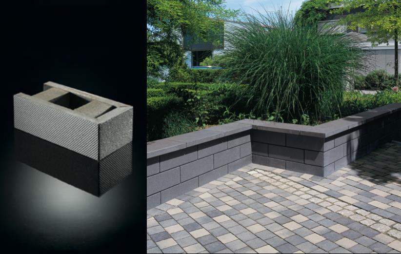
4 SYSTEM DESCRIPTION 2 The BelMuro is a wall system designed to bridge embankments. Moreover, BelMuro can be used as a freestanding wall system. The BelMuro blocks are factory-produced cuboid concrete elements featuring two chambers arranged in a row. Any wall over 1 m in height may be subject to permit requirements and engineering analysis. Always consult with your local authorities before beginning your project. This system should only be installed by trained, professional contractors to ensure a safe, consistent, reliable system that will be long-lasting. TOOLS YOU WILL NEED WHEELBARROW CHALK LINE RUBBER MALLET MEASURING TAPE PEGS CONCRETE SAW LEVEL VIBRATING PLATE 2


5 LINE AND PINS CEMENT MIXER SHOVEL SEALANT GUN 3 MATERIALS AND SPECIFICATIONS 1 - BelMuro Walling System units: Conforming to DIN EN Square brick 505 mm x 165 mm x 252 mm 1/2-Square brick 255 mm x 165 mm x 252 mm End stone 505 mm x 165 mm x 252 mm 1/2-End stone 255 mm x 165 mm x 252 mm 2- Coping Options: Natural Edge Coping Natural Collection 300 mm x 1200 mm x 50 mm 300 mm x 1800 mm x 50 mm Fullnose Coping Natural Collection 300 mm x 1200 mm x 50 mm 300 mm x 1800 mm x 50 mm 3
6 Coping Unit Ledgestone Collection 305 mm x 610 mm x 70 mm Closed End Coping Ledgestone Collection 305 mm x 610 mm x 70 mm 4 3- Concrete: CSA A23.1, minimum 20 MPa (3000 psi) compressive strength at 28 days. 4- Mortar: CAN/CSA A179, Type S based on proportion specifications. 5- Grout: CAN/CSA A179, pre-mixed type, minimum 12.5 MPa compressive strength at 28 days such as Coarse Masonry Grout by Maxi-Mix. 6- Reinforcing bars: CSA-G30.18, #M10, billet steel, grade 350, deformed bars. 7 Seal Profiles: As supplied with the BelMuro blocks. 8 Silicone Adhesive and Sealant: ASTM C920, Type S, Grade NS, Class 50, Use T, NT, M, G, A, and O silicone material such as Unilock Concrete Adhesive. 9 Geogrid*: extruded polypropylene, bi-axial, single layer with opening configuration either square or rectangular in shape, labelled in accordance with ASTM D4873. Tensile strength as specified by the engineer. * Reinforced Retaining Wall System with Geogrid Only 4

7 DRY STACK SYSTEM: INSTALLATION GUIDE FOR WALLS UP TO 508 MM IN HEIGHT. PREPARATION AND PLANNING 1. Draw a detailed sketch of the retaining wall or steps showing layout and dimensions. Determine whether you will need a shallow or deep excavation based on the height of your wall. Alternatively, refer to the professional details produced for the retaining wall Prior to digging, always check with local utility companies to perform a "utilities locate" for any potential underground utilities. 3. If applicable, check with the local municipality to inquire about minimum setback requirements and building permit requirements. 4. Determine the type of soil present on the site and the depth of the water table. Local building officials are often in a position to provide useful advice regarding local conditions. Do not build on expansive soil, liquefiable soils or other questionable soils, unless the soil has been specially prepared in accordance with recommendations of a civil or geotechnical engineer 5
8 TRENCH EXCAVATION 1. Begin by laying out the edges of the concrete pad with batter boards. 2. Use the mason's line, pegs and chalk to lay out the width of the concrete pad. Dig the trench at 6 the lines marked. 3. Make sure you remove any surface vegetation and organic materials. 4. Line excavation with minimum 25 mm granular fill and compact using vibrating plate to minimum 95% Proctor Density to provide a levelling bed. FOUNDATION (CHOICE OF: CAST-IN-PLACE OR PRECAST CONCRETE PAD) 1. Cast-in-place Concrete pad: Pads should project beyond each side of the wall by at least 100 mm. Minimum 252 mm wide x Minimum 100 mm deep. 2. Drive stakes into the ground and mark the depth of the pad at the top. Stakes should be no more than 2400 mm apart. 3. Use 2x8 and attach them to the stakes to create the forms for the concrete pour. Reinforce the form with 1x2 spreaders installed 600 to 900 mm apart. Make sure everything is level. 4. Mix and place the concrete in accordance with the concrete supplier/manufacturer s instructions. 5. Screed the forms to produce a smooth and level surface. 6. Cover the concrete with burlap after placing to allow for curing; the concrete should be kept damp. 6
9 ALTERNATIVE: Use "12 - Pisa2 Coping Precast Unit - 300x600x75mm" furnished by Unilock as a base for the wall. Install this unit on level and properly compacted ground to ensure a durable installation. INSTALLING THE FIRST COURSE 7 1. Install a drainage pipe (weeper tile) along the rear face of the trench to allow proper drainage for all walls over 1.2 m and all walls installed in silty or clay soils. 2. Apply a 25 mm thick layer of mortar to the exposed section of concrete pad and furrow it lightly. Set the first course of block in the mortar. 3. Use a level to ensure the first course is level side-to-side and front-to-back. 7
10 INSTALLING THE REMAINING COURSES 1. Start the second row with a 1/2 block offset and place each piece tightly together. Secure the blocks together using beads of construction adhesive. 2. Install plastic T spacers at regular intervals at the back of every course to ensure proper spacing. Seal the back joints with silicone adhesive. 3. Seal the face joints using the rubber seal profiles (supplied with the blocks) by laying 8 the seal profiles flush with the inside surface immediately after setting each block. Angle the seal profiles into place in order to fit them to the notch in the vertical joints. 4. Repeat this process until the desired height of the wall is reached (do not exceed 4 courses). REMEMBER: Expansion joints must be installed at intervals of 5 to 8 m, in order to prevent crack formation. You can produce these expansion joints by leaving a chamber created between two adjacent blocks unreinforced and filling it with coarse aggregate instead (grain size 8-16 mm). COPING THE WALL 1. Install coping blocks by setting them in mortar. 2. Fill the chambers up to the top edge of the seal profile to create the mortar bed. 3. Seal all joints of the coping blocks with silicone sealants in order to prevent rainwater from penetrating into the wall. 8

11 GEOGRID WALL SYSTEM: INSTALLATION GUIDE FOR WALLS UP TO 508 MM IN HEIGHT. 9 PREPARATION AND PLANNING Conform to requirements noted on Page 5. TRENCH EXCAVATION Conform to requirements noted on Page 6. In addition: Be sure to remove existing soils in the reinforced soil area to the maximum embedment length of the geogrid. Provide a level soil conditions behind wall units for the placement of each geogrid layer. 9
12 FOUNDATION (CHOICE OF: CAST-IN-PLACE OR PRECAST CONCRETE PAD) Conform to requirements noted on Page INSTALLING THE FIRST COURSE Conform to requirements noted on page 7. In addition: Fill the hollow chambers of the base course and a minimum of 300 mm behind the wall with backfill material. 10
13 INSTALLING THE REMAINING COURSES 1. Use the vibrating plate compactor to compact the backfill material immediately behind the blocks. Compact parallel to the wall. Work from the back of the blocks to the back of the backfill material. 2. Ensure the base course is level and adjust as necessary. 3. Compact all backfill soils to minimum 95% Standard Proctor density. 4. Use equipment appropriate for the soil being compacted Start the second row with a 1/2 block offset and place each piece tightly together. Secure the blocks together using construction adhesive. 6. Every course after the first course requires compaction. 7. Geogrid Installation: a. Place the geogrid as you install the blocks and as you place and compact backfill material for each course. (Refer to backfilling section) b. Cut sections from geogrid roll to a depth of 1.75 m. c. Install the geogrid without folds every third course and stretched out smooth. Make sure geogrid is placed within 25 mm of wall face. d. Secure the back edge of the geogrid before and during backfill and compaction. e. Ensure geogrids cover the respective reinforcement layer completely. In order to achieve this, overlap multiple layers of geogrid by approximately 100 mm. No overlapping is permitted in the main tensile strength direction (roll direction). f. Provide a minimum of 150 mm backfill coverage prior to driving equipment over the geogrid. Avoid driving or turning vehicles directly on geogrid. The fill soil must be firmly compacted using suitable compaction equipment. 8. Install plastic T spacers at regular intervals at the back of every course to ensure proper spacing. Seal the back joints with beads of silicone adhesive. 9. Seal the joints using the seal profiles (supplied with the blocks) by laying the seal profiles flush with the inside surface immediately after setting each block. Angle the seal profiles into place in order to fit them to the notch in the vertical joints. 11
14 10. Install Granular A or Granular B material in block chambers and 300 mm behind the wall. Use approved to backfill soils behind the Granular A or Granular B material in the reinforced zone. 11. All Granular A or Granular B material and backfill soils within 0.9 m of the wall must be properly compacted using a mechanical plate compactor. Compact in maximum 200 mm, starting on the block and working in a path that runs parallel to the block towards the back of the reinforced zone Compact all materials to a minimum 95% Standard Proctor density. 13. Check and adjust for level, alignment and the wall batter as the wall is erected. 14. Remove all excess Granular A or Granular B material and ridges or slag material from the top surface of all units. 15. Repeat above steps until you reach your desired wall height. REMEMBER: Expansion joints must be installed at intervals of 5 to 8 m, in order to prevent crack formation. You can produce these expansion joints by leaving a chamber created between two adjacent blocks unreinforced and filling it with coarse aggregate instead (grain size 8-16 mm). INFILLING AND BACKFILLING 1. Use granular materials such as OPSS 'Granular A' or 'Granular B' as infill material in the block cores. 2. All other native backfill material should be prepared as necessary to be nonexpansive, free of debris, organic material and clods or rocks larger than 100 mm. 3. Backfill each course. Fill open spaces between units and block chambers, and 300 mm zone behind the wall with 'Granular A' or 'Granular B' material. 4. Ensure the backfill is dewatered. 5. Backfill each course in increments of 150 mm and compact with appropriate compaction equipment. Backfill and compact behind each course before installing additional courses. 6. Do not use heavy ride-on compaction equipment within 1m from back of wall. Do not use jumping or ramming type compaction. 12

15 COPING THE WALL 1. Conform to requirements noted on page 8. MASONRY WALL SYSTEM: INSTALLATION GUIDE All walls described in this section should be subject to an engineering analysis by a local civil or geotechnical engineer and built to the approved plans and specifications provided by the engineer. 13 PREPARATION AND PLANNING Conform to requirements noted on Page 5. In addition: determine the exact locations of the Sonotube piers before beginning the excavation. TRENCH EXCAVATION Conform to requirements noted on Page 6. Except: excavate minimum 150 mm below the frost line (1.2 m in most places in Ontario) at all Sonotube pier locations. Provide minimum 150 mm compacted granular material to serve as a leveling bed. 13
16 FOUNDATION (CAST-IN-PLACE CONCRETE PAD WITH SONOTUBE PIERS) Conform to requirements noted on Page 6. In addition: strictly conform to Sonotube manufacturer s installation instructions for the installation of all Sonotube piers. 14 INSTALLING THE FIRST COURSE Conform to requirements noted on page 7. 14
17 INSTALLING THE REMAINING COURSES 1. Start the second row with a 1/2 block offset and place each piece tightly together. Secure the blocks together using construction adhesive. 2. Seal the joints using the seal profiles (supplied with the blocks) by laying the seal profiles flush with the inside surface immediately after setting each block. Angle the seal profiles into place in order to fit them to the notch in the vertical joints Repeat this process until you reach 1 m of height. You are now ready to fill the chambers with grout. 4. Pour grout in the chambers in accordance with the grout manufacturer s recommendations up to approximately 100 mm below the upper edge of the wall. 5. Overlap the reinforcement bars by approximately 900 mm and, depending on the total height of the wall, extend them up to an additional 1 m below the full height of the wall. 6. Lay the additional block courses (including seal profile). 7. Fill the chambers with grout up to approximately 20 mm below the upper edge. REMEMBER: Expansion joints must be installed at intervals of 5 to 8 m, in order to prevent crack formation. You can produce these expansion joints by leaving a chamber created between two adjacent blocks unreinforced and filling it with coarse aggregate instead (grain size 8-16 mm). BACKFILLING 1. All native backfill material should be prepared as necessary to be non-expansive, free of debris, organic material and clods or rocks larger than 100 mm. 2. Backfill each course. Fill open spaces between units and the 300 mm zone behind the wall with 'Granular A' or 'Granular B' material. 3. Ensure the backfill is dewatered. 4. Backfill each course in increments of 150 mm and compact with appropriate compaction equipment. Backfill and compact behind each course before installing additional courses. 15
18 5. Do not use heavy ride-on compaction equipment within 1m from back of wall. Do not use jumping or ramming type compaction. COPING THE WALL 1. Conform to requirements noted on page

19 STEPS: INSTALLATION GUIDE 17 PREPARATION AND PLANNING 1. Conform to requirements noted on Page 5. FOUNDATION (CHOICE OF: CAST-IN-PLACE OR PRECAST CONCRETE PAD) Conform to requirements noted on Page 6. STEP INSTALLATION 1. Mark a line on the ground to determine the edge of the first riser. 2. Build the first riser with the standard Belmuro units along the pre-determined and marked line. Fill the blocks chambers with native infill material 3. Position the coping units on top of the riser and secure with adhesive. 17
20 4. Seal all joints of the coping blocks with silicone sealants to prevent rainwater from penetrating into the wall. 5. Trim the coping as necessary. The maximum overhang for each step should not exceed 38 mm. 6. Backfill the first course with the granular A base material and compact to 95% Standard Proctor Density. Refer to instructions on page 15 for additional information Ensure the top elevation of the base is flush with the top elevation of lower units. 8. Ensure the face of riser units is in contact with the back of the coping units on the lower course. 9. Position the coping units on top and secure with adhesive. 10. Repeat steps 4 to 7 to continue the risers until you finish the steps. 18
COUNTY BLOCK. Construction Guidelines on County Block Steps. Special Considerations When Building Steps. Natural Beauty Absolute Strength
 Construction Guidelines on County Block Limits of Liability This County Block Installation Guide provides general information about the product, including installation procedures, technical and engineering
Steps And Stairs Installation Option 1 - Steps In Wall Option 2 - Steps With Plant Space Option 3 - Steps In Front of Walls Option 4 - Steps Along
 Steps And Stairs Installation Option 1 - Steps In Wall Option 2 - Steps With Plant Space Option 3 - Steps In Front of Walls Option 4 - Steps Along Wall Face Option 5 - Steps In Wall; 10 (25cm) Tread Option
Steps And Stairs Installation Steps In Wall - Option 1 Steps In Front of Walls - Option 2 Steps In Wall; 10 (25cm) Tread - Option 3 Step Parallel to
 Tread - Option 3 Step Parallel to") Steps And Stairs Installation Steps In Wall - Option 1 Steps In Front of Walls - Option 2 Steps In Wall; 10 (25cm) Tread - Option 3 Step Parallel to Wall - Option 4 Steps and Stairs Q & A E CONSTRUCTION
Steps And Stairs Installation Steps In Wall - Option 1 Steps In Front of Walls - Option 2 Steps In Wall; 10 (25cm) Tread - Option 3 Step Parallel to Wall - Option 4 Steps and Stairs Q & A E CONSTRUCTION
Gravity Wall. A force to be reckoned with... Gravity (SRW) segmental retaining wall systems are structures
 segmental retaining wall systems are structures") A force to be reckoned with... Gravity (SRW) segmental retaining wall systems are structures lower in height that use the FrogStone unit weight combined with gravel core infill to resist earth pressures
A force to be reckoned with... Gravity (SRW) segmental retaining wall systems are structures lower in height that use the FrogStone unit weight combined with gravel core infill to resist earth pressures
CONTENT. INTrOduCTION 3. units & CONNECTOrs 4. standard INsTallaTION PrOCEdurEs 5
 CONTENT INTrOduCTION 3 units & CONNECTOrs 4 standard INsTallaTION PrOCEdurEs 5 step 1 - Preconstruction Preparation 5 step 2 - Prepare the leveling Pad 5 step 3 - Install the Base Course 5 step 4 - Geogrid
Bordeaux Walling. Product & Technical Information
 Product & Technical Information BORDEAUX WALLING Piece Piece Piece Block Block Block Block Pins No. per per Height Length Width Weight Layer Cube (kgs) 1 2 3 1 2 10 150 400/350 250 28 Yes 2 2 10 150 300/300
Garden WallScape Installation Guide
 By CornerStone Wall Solutions Inc. Garden WallScape Installation Guide GRAVITY/DETAILS The perfect balance... between design and nature Garden WallScape Overview note: bolded terms are defined in our online
WATER AND DRAINAGE. Drainage Around Walls Water Applications Drainage Structures Water and Drainage Q & A
 WATER AND DRAINAGE Drainage Around Walls Water Applications Drainage Structures Water and Drainage Q & A H CONSTRUCTION H-1 W A T E R A N D D R A I N A G E DRAINAGE AROUND WALLS Poor drainage is a leading
SECTION SPECIFICATION FOR STONEBRIDGE RETAINING WALL SYSTEM
 SECTION 32 32 23 SPECIFICATION FOR STONEBRIDGE RETAINING WALL SYSTEM PART 1: GENERAL 1.01 Scope Work includes furnishing all materials, labor, equipment, and supervision to install a Stonebridge segmental
67665_MesaInstallationGuide_2 12/10/07 2:12 PM Page 1 E ID U G TION ALLA T INS
 INSTALLATION GUIDE Introduction The Mesa Retaining Wall Systems from Tensar International Corporation offer superior and costeffective solutions for all of your retaining wall needs. This installation
Construction Specification for Utility Adjustments
 Engineering & Construction Services Division Standard Specifications for Road Works TS 4.50 September 2017 for Utility Adjustments Table of Contents TS 4.50.01 SCOPE... 2 TS 4.50.02 REFERENCES... 2 TS
Anchorplex retaining wall construction guide. Building. Anchorplex. Retaining Wall Systems
 Anchorplex retaining wall construction guide Building Anchorplex Retaining Wall Systems Table of Contents and ow to Use This Guide table of contents ow to Use This Guide. 2 About the Anchorplex System.
MagnumStone Specifications Gravity
 MagnumStone Specifications Gravity SPECIFICATION FOR MAGNUMSTONE GRAVITY MECHANICALLY STABILIZED EARTH SYSTEM PART 1: GENERAL.01Description The work consists of supplying and installing all aspects of
Every effort has been made to accurately represent the colors. However, the colors may vary slightly due to the concrete manufacturing process or
 1 Every effort has been made to accurately represent the colors. However, the colors may vary slightly due to the concrete manufacturing process or this printing process. We recommend viewing actual color
CONCRETE SEGMENTAL RETAINING WALLS
 32 32 23.13 CONCRETE SEGMENTAL RETAINING WALLS 1.00 GENERAL 1.01 DESCRIPTION A. The work shall consist of furnishing and installing concrete segmental retaining wall (CSRW) units to the lines, grades and
Building. Anchorplex. Retaining Wall Systems
 Building Anchorplex Retaining Wall Systems Table of Contents and Introduction table of contents ow to Use This Guide 2 About the Anchorplex System 2 Anchorplex System Material Specifications 3 Anchorplex
LANDSCAPE RETAINING WALLS
 SUDAS Standard Specifications Division 9 - Site Work and Landscaping Section 9070 - Landscape Retaining Walls LANDSCAPE RETAINING WALLS PART - GENERAL.0 SECTION INCLUDES A. Modular Block Retaining Walls
SPECIFICATIONS FOR PRECAST MODULAR BLOCK RETAINING WALL SYSTEM (revised 9/17/18)
") Page 1 of 8 STONE STRONG SYSTEMS SPECIFICATIONS FOR PRECAST MODULAR BLOCK RETAINING WALL SYSTEM (revised ) PART 1: GENERAL 1.01 Description A. Work includes furnishing and installing precast modular blocks
Page 1 of 8 STONE STRONG SYSTEMS SPECIFICATIONS FOR PRECAST MODULAR BLOCK RETAINING WALL SYSTEM (revised ) PART 1: GENERAL 1.01 Description A. Work includes furnishing and installing precast modular blocks
SPECIFICATIONS FOR PRECAST MODULAR BLOCK RETAINING WALL SYSTEM (revised 5/8/7)
") Page 1 of 7 STONE STRONG SYSTEMS SPECIFICATIONS FOR PRECAST MODULAR BLOCK RETAINING WALL SYSTEM (revised 5/8/7) PART 1: GENERAL 1.01 Description A. Work includes furnishing and installing precast modular
Page 1 of 7 STONE STRONG SYSTEMS SPECIFICATIONS FOR PRECAST MODULAR BLOCK RETAINING WALL SYSTEM (revised 5/8/7) PART 1: GENERAL 1.01 Description A. Work includes furnishing and installing precast modular
SPECIFICATION FOR MAGNUMSTONE GEOGRID REINFORCED Mechanically Stabilized Earth (MSE) SYSTEM
 SYSTEM") MagnumStone Specifications Geogrid Reinforced SPECIFICATION FOR MAGNUMSTONE GEOGRID REINFORCED Mechanically Stabilized Earth (MSE) SYSTEM PART 1: GENERAL 1.01 Description The work consists of supplying
MagnumStone Specifications Geogrid Reinforced SPECIFICATION FOR MAGNUMSTONE GEOGRID REINFORCED Mechanically Stabilized Earth (MSE) SYSTEM PART 1: GENERAL 1.01 Description The work consists of supplying
SPECIFICATION FOR CORNERSTONE GEOGRID REINFORCED SEGMENTAL RETAINING WALL SYSTEM
 CornerStone Specifications Geogrid Reinforced SPECIFICATION FOR CORNERSTONE GEOGRID REINFORCED SEGMENTAL RETAINING WALL SYSTEM PART 1: GENERAL 1.01 Description The work consists of supplying and installing
Retaining Wall Systems
 Retaining Wall Systems A family of Retaining Wall Products The versatile Allan Block product line allows easy design and construction of retaining walls to meet specific engineering and site requirements.
Construction Procedures
 Construction Procedures 2014 Rev. 1.6 1 Introduction This manual presents the methods and procedures necessary for the proper erection of a LOCK+LOAD retaining wall. problems later during the service life
SECTION Segmental Concrete Unit Masonry Retaining Wall Height Over 5-0 High
 PART 1: GENERAL 1.0 0 Scope of Standards A. This standard provides general guidance concerning the specific preferences of the Texas State University for a Segmental Retaining Wall up to 5-0 high. B. Texas
SECTION MECHANICALLY STABILIZED EARTH RETAINING WALLS
 SECTION 13100 MECHANICALLY STABILIZED EARTH RETAINING WALLS PART 1 -- GENERAL 1.01 THE REQUIREMENT A. Includes all labor, material, equipment, testing and submittals required to design and complete construction
(SIZE) MANHOLES CATCH BASINS AND DITCH INLETS -Item No. ADJUSTING AND REBUILDING MANHOLES, CATCH BASINS AND DITCH INLETS - Item No.
 MANHOLES CATCH BASINS AND DITCH INLETS -Item No. ADJUSTING AND REBUILDING MANHOLES, CATCH BASINS AND DITCH INLETS - Item No.") (SIZE) MANHOLES CATCH BASINS AND DITCH INLETS -Item No. ADJUSTING AND REBUILDING MANHOLES, CATCH BASINS AND DITCH INLETS - Item No. Special Provision No. 407S06 July 2010 Aggregate Requirements, Lift Rings,
(SIZE) MANHOLES CATCH BASINS AND DITCH INLETS -Item No. ADJUSTING AND REBUILDING MANHOLES, CATCH BASINS AND DITCH INLETS - Item No. Special Provision No. 407S06 July 2010 Aggregate Requirements, Lift Rings,
Construction Procedures
 Construction Procedures 2016 Rev. 1.7 1 Contents Introduction...... 3 Base Row Layout........ 4 Drainage and Backfill..... 6 Compaction... 7 Subsequent Rows... 8 In Pictures.... 10 Variations.. 11 Step
A. Modular Unit - A concrete wall interlocking element, machine made from portland cement, water and aggregates.
 Section 02832 - Page 1 PART 1 - GENERAL 1.1 SUMMARY 1.2 DEFINITIONS 1.3 SUBMITTALS 1.4 JOB MOCK-UP A. This section includes furnishing and installation of modular interlocking concrete masonry units bearing
TERRASTOP SYSTEM 2 RETAINING WALLS. Section Page 1 PART 1 - GENERAL 1.1 SUMMARY
 Section 02832 - Page 1 PART 1 - GENERAL 1.1 SUMMARY 1.2 DEFINITIONS 1.3 SUBMITTALS 1.4 JOB MOCK-UP A. This section includes furnishing and installation of modular interlocking concrete masonry units bearing
Wmega Retaining Wall Specification
 Wmega Retaining Wall Specification 1. General 1.01 Description A. This work shall consist of furnishing and installing an Ωmega Segmental Retaining Wall System in accordance with these specifications and
Reinforced Earth wall Construction Manual
 COVER PAGE CT-PE-W02 Rev: 5 Reinforced Earth wall Construction Manual Concrete Facing Reinforced Earth Malaysia Sdn Bhd 80-1, Jalan 8/62A Bandar Menjalara 52200 Kuala Lumpur Tel : 03-62746162, Fax : 03-62747212
NOVEMBER 2016 GRANDWALL. retaining walls installation guide
 NOVEMBER 2016 GRANDWALL retaining walls installation guide RETAINING WALL INSTALLATION GUIDE RETAINING WALL information Austral Masonry Grandwall retaining wall blocks are an ideal choice for retaining
SECTION CONCRETE SEGMENTAL RETAINING WALL SYSTEM
 SECTION 02832 CONCRETE SEGMENTAL RETAINING WALL SYSTEM PART 1.: GENERAL 1.01 WORK INCLUDED A. This section includes the following: The Specifications on furnishing the design, materials and labor required
How To Install Your Cambridge Pavingstones System How To Install Your Cambridge Segmental Retaining Wall System
 4 How To Install Your Cambridge Pavingstones System Step 1. Preparation: Sketch a diagram of area to be paved. Square off a 90-degree corner. Set stakes for outside perimeters 6 inches away from area.
Anchorplex retaining wall construction guide
 Anchorplex retaining wall construction guide Building Anchorplex Retaining Wall Systems Table of Contents and Introduction table of contents ow to Use This Guide......................... 2 About the Anchorplex
ITEM D-701 PIPE FOR STORM DRAINS AND CULVERTS
 ITEM D-701 PIPE FOR STORM DRAINS AND CULVERTS 701-1 DESCRIPTION 701-1.1 This item shall consist of the construction of pipe culverts, and storm drains, removal of existing storm pipes, connections to existing
CONSTRUCTION SPECIFICATION FOR THE INSTALLATION OF ELECTRICAL CHAMBER
 ONTARIO PROVINCIAL STANDARD SPECIFICATION METRIC OPSS 602 MARCH 1993 CONSTRUCTION SPECIFICATION FOR THE INSTALLATION OF ELECTRICAL CHAMBER 602.01 SCOPE 602.02 REFERENCES 602.05 MATERIALS TABLE OF CONTENTS
GEOGRID CONNECTION DETAIL OLYMPIA RADIUS UNIT
 PLACE TWO STANDARD CONNECTORS IN EACH UNIT AS SHOWN (VERTICAL ORIENTATION) INSERT TWO CONNECTORS PER HORIZONTALLY ORIENTED BLOCK; INSERT ONE CONNECTOR PER VERTICALLY ORIENTED BLOCK SHIM BETWEEN BLOCK COURSES
Strengthened Soil Wall Construction Manual
 Strengthened Soil Wall Construction Manual This information has been prepared by Shaw Technologies, Inc. as an aid in constructing their Strengthened Soil Wall system. Final determination of the suitability
Building Construction
 Building Construction Shallow Foundations Module-III Introduction The foundation can be classified broadly into two types: Shallow foundations Deep foundations Shallow foundations Shallow Foundations When
CONSTRUCTION SPECIFICATION FOR NOISE BARRIER SYSTEMS
 ONTARIO PROVINCIAL STANDARD SPECIFICATION METRIC OPSS 760 NOVEMBER 2014 CONSTRUCTION SPECIFICATION FOR NOISE BARRIER SYSTEMS TABLE OF CONTENTS 760.01 SCOPE 760.02 REFERENCES 760.03 DEFINITIONS 760.04 DESIGN
TILT-UP PRECAST CONCRETE SANDWICH PANELS. A. Work includes, but is not limited to, the following:
 PART 1 GENERAL 1.01 SUMMARY SECTION 03460 TILT-UP PRECAST CONCRETE SANDWICH PANELS A. Work includes, but is not limited to, the following: 1. Architectural precast concrete sandwich wall panels. 2. Integral
VERSA-Green TM Plantable Retaining Wall System
 www.versa-lok.com VERSA-Green TM Plantable Retaining Wall System VERSA-GREEN INSTALLATION The VERSA-Green Plantable Wall System from VERSA-LOK is truly the greenest retaining wall available. It combines
SEGMENTAL BLOCK RETAINING WALLS. Comply with Division 1 - General Provisions and Covenants, as well as the following:
 SEGMENTAL BLOCK RETAINING WALLS PART 1 - GENERAL 1.01 SECTION INCLUDES Segmental Block Retaining Walls 1.02 DESCRIPTION OF WORK Constructing segmental block retaining walls. 1.03 SUBMITTALS Comply with
Section ( ) SPECIFICATION FOR SEGMENTAL CONCRETE UNIT RETAINING WALL
 SPECIFICATION FOR SEGMENTAL CONCRETE UNIT RETAINING WALL") Section 02834 (32 32 23) SPECIFICATION FOR SEGMENTAL CONCRETE UNIT RETAINING WALL PART 1: GENERAL 1.01 Description A. Work shall consist of furnishing and construction of a County Materials Retaining Wall
Section 02834 (32 32 23) SPECIFICATION FOR SEGMENTAL CONCRETE UNIT RETAINING WALL PART 1: GENERAL 1.01 Description A. Work shall consist of furnishing and construction of a County Materials Retaining Wall
Uwall UNIVERSAL CONSTRUCTION MANUAL
 Uwall UNIVERSAL Retaining Wall System CONSTRUCTION MANUAL TM President s Letter CSI is a leader in its industry supplying precast infrastructure products throughout New England and beyond since 1972, developing
Redi Rock Specification and Installation Manual
 Redi Rock Specification and Installation Manual 1.0 General Scope This Specification covers the Design, Materials and Installation of Redi Rock modular block Retaining and Freestanding Wall systems as
STORMCAPTURE. Installation Manual
 STORMCAPTURE Installation Manual Introduction Site Preparation Delivery & Installation LinkSlabs Backfill Introduction StormCapture (shown in Figure 1) is a total stormwater management system. The highly-configurable
CONCRETE SEGMENTAL RETAINING WALL SYSTEM
 CONCRETE SEGMENTAL RETAINING WALL SYSTEM PART 1: GENERAL SPECIFICATIONS 1.01 Work Included A. Work shall consist of furnishing and constructing a Rockwood Classic 8, Classic 6 and Legend unit segmental
MACHINE-LAY Installation Manual
 MACHINE-LAY Installation Manual PaveDrain Installation Manual Table of Contents Section 1: Base Preparation (pages 3 6) Section 2: Machine-Lay PaveDrain Blocks (pages 8 11) Section 3: Edge Restraints (pages
SECTION SEGMENTAL RETAINING WALL
 Note: This guide specification should not be included entirely as-is. Specification writers must edit areas in red which may or may not be relevant to a specific project or where mutually exclusive choices
CONSTRUCTION SPECIFICATION FOR CONCRETE UNIT PAVERS
 CITY OF TORONTO STANDARD CONSTRUCTION SPECIFICATIONS FOR ROADS TS 3.80 November 2010 CONSTRUCTION SPECIFICATION FOR CONCRETE UNIT PAVERS INDEX TS 3.80.01 SCOPE... 2 TS 3.80.02 REFERENCES... 2 TS 3.80.03
Installation Step By Step Geogrid Installation Installation Q & A
 Installation Step By Step Geogrid Installation Installation Q & A C CONSTRUCTION C-1 With proper design methods, Keystone Retaining Walls can be built to retain a variety of site conditions. Before construction
G R A V I T Y / G E O G R I D
 GRAVITY/GEOGRID MAGNUMSTONE Overview note: bolded terms are defined in our online glossary at www.cornerstonewallsolutions.com The MagnumStone retaining wall system was developed with the installer in
Five Stone System. Trench Depth Compactible Rock. Foundation. 57 lbs 41 lbs 31 lbs 47 lbs. Patent Pending. Approximate Weight
 Five Stone System Patent Pending Introduction to the Multi-Use, Multi-Stone System The multi-use, multi-stone system has been developed to give a natural stone appearance to a manufactured system. The
SECTION TILT-UP PRECAST CONCRETE SANDWICH PANELS. A. Work includes, but is not limited to, the following:
 PART 1 GENERAL 1.01 SUMMARY SECTION 03460 TILT-UP PRECAST CONCRETE SANDWICH PANELS A. Work includes, but is not limited to, the following: 1. Architectural precast concrete sandwich wall panels. 2. Integral
HOW TO BUILD Garden Walls Frestanding & Landscape Walls
 HOW TO BUILD Garden Walls Frestanding & Landscape Walls 10 Cambridge Wall Book Garden walls This layout depicts a common application of landscape and freestanding designs together in one wall with Columns
CONSTRUCTION SPECIFICATION FOR CONCRETE CROSSWALK INDEX TS SCOPE...3
 CITY OF TORONTO TS 3.65 TRANSPORTATION SERVICES STANDARD CONSTRUCTION SPECIFICATIONS June 2001 CONSTRUCTION SPECIFICATION FOR CONCRETE CROSSWALK INDEX TS 3.65.01 SCOPE...3 TS 3.65.02 TS 3.65.03 REFERENCES...3
SPECIFICATION FOR REINFORCED SOIL WALL
 SPECIFICATION FOR REINFORCED SOIL WALL 1.0 EXTENT OF WORK The work shall consist of Reinforced Soil walls built in accordance with this specification and in conformity with the lines, levels and details
NOVEMBER 2016 MAGNUMSTONE. retaining walls installation manual
 NOVEMBER 2016 MAGNUMSTONE retaining walls installation manual AUSTRAL MASONRY CONTENTS Magnumstone Installation Guide 04 Overview 07 Unit Specifications 08 Installation 08 Gravity MagnumStone Wall 16 Geogrid
SECTION UTILITY MANHOLES AND STRUCTURES
 SECTION 33 05 14 UTILITY MANHOLES AND STRUCTURES PART 1 GENERAL 1.1 SUMMARY A. Section Includes: 1. Precast reinforced concrete manholes and structures with tongue-and-groove joints with masonry transition
CONSTRUCTION SPECIFICATION FOR PRECAST REINFORCED CONCRETE BOX CULVERTS AND BOX SEWERS IN OPEN CUT
 ONTARIO PROVINCIAL STANDARD SPECIFICATION METRIC OPSS 422 APRIL 2004 CONSTRUCTION SPECIFICATION FOR PRECAST REINFORCED CONCRETE BOX CULVERTS AND BOX SEWERS IN OPEN CUT TABLE OF CONTENTS 422.01 SCOPE 422.02
Special Provision No. 799F01 March 2012 CONSTRUCTION SPECIFICATION FOR THE INSTALLATION OF NOISE BARRIER TABLE OF CONTENTS
 ... m NOISE BARRIER - Item No.... m NOISE BARRIER INCLUDING PRECAST NOISE/TRAFFIC BARRIER - Item No.... m NOISE BARRIER ON STRUCTURES - Item No.... m SALVAGEABLE NOISE BARRIER - Item No.... m SALVAGEABLE
PaveDrain Installation Manual. Table of Contents. Hand-Placement of individual PaveDrain Units. PaveDrain End Cap
 Installation Manual PaveDrain Installation Manual Table of Contents Section 1: Base Preparation Section 2: Hand-Placement of individual PaveDrain Units Section 3: Mattress Installation Section 4: PaveDrain
MODULAR CONCRETE RETAINING WALL
 MODULAR CONCRETE RETAINING WALL PART 1: GENERAL 1.01 Description A. Work shall consist of furnishing and construction of a KEYSTONE Retaining Wall System or equal in accordance with these specifications
Installation Guidelines
 815 NE 172 nd Avenue Vancouver, WA 98684 877-694-0141 Installation Guidelines Installation steps include job planning, layout, excavating and preparing the soil subgrade, applying geotextiles (optional),
PLATON FOUNDATION WRAP
 DRAINAGE SOLUTIONS SINCE 1908 PLATON FOUNDATION WRAP RUGGED, DIMPLED HIGH-DENSITY POLYETHYLENE (HDPE) MEMBRANE THAT KEEPS FOUNDATIONS DRY ADVANCED TECHNOLOGY EASY INSTALLATION PROVEN PERFORMANCE ARMTEC.COM
2.1.2 Minimum wall thickness shall be 90 mm Frames and covers shall be bitumen coated by dipping.
 1.0 GENERAL 1.1 Scope 2.0 PRODUCTS 1.1.1 The work shall consist of the construction, renovation or the adjustment of manholes and/or catchbasins as detailed on the plans or where designated by the Engineer
Retaining Wall Systems
 Retaining Wall Systems Construction & Quality Control Tensar Earth Technologies, Inc. Manual CONSTRUCTION & QUALITY CONTROL This manual provides general guidelines for construction and quality control
CONSTRUCTION SPECIFICATION FOR CONCRETE SIDEWALK AND CONCRETE RAISED MEDIAN INDEX TS SCOPE...3 TS DEFINITIONS...3
 CITY OF TORONTO TS 3.70 TRANSPORTATION SERVICES STANDARD CONSTRUCTION SPECIFICATIONS June 2001 CONSTRUCTION SPECIFICATION FOR CONCRETE SIDEWALK AND CONCRETE RAISED MEDIAN INDEX TS 3.70.01 SCOPE...3 TS
Installation Guide ATX
 Installation Guide ATX ATX Contents This guide, provided at no cost by Risi Stone Inc. is intended to serve only as an informational resource for Architextures product purchasers. It is provided for reference
Special Provision No. 599F01 May 2004 CONSTRUCTION SPECIFICATION FOR THE INSTALLATION OF NOISE BARRIER TABLE OF CONTENTS
 ... m NOISE BARRIER - Item No.... m NOISE BARRIER INCLUDING PRECAST NOISE/TRAFFIC BARRIER - Item No.... m NOISE BARRIER ON STRUCTURES - Item No.... m SALVAGEABLE NOISE BARRIER - Item No.... m SALVAGEABLE
PISA. Retaining Wall System. The choice of professional contractors
 PISA Retaining Wall System The choice of professional contractors PRODUCT CODE DESCRIPTION & DIMENSIONS (H x W x D) ~ WEIGHT PER UNIT No./M² No./ Lin M² UNITS PER PALLET 5501 Light Vertical Straight Unit
Wall Modular Block Mechanically Stabilized Earth, Item S.
 Wall Modular Block Mechanically Stabilized Earth, Item 532.0300.S. A Description (1) This special provision describes designing, furnishing materials and erecting a permanent earth retention system in
SECTION 303 CULVERTS
 303.01 Scope - This section covers the construction of pipe culverts. 303.01.01 Definitions for the purposes of this section, the following general terms are defined as follows: a) Backfilling means the
CONSTRUCTION SPECIFICATION FOR PRECAST REINFORCED CONCRETE BOX CULVERTS AND BOX SEWERS IN OPEN CUT
 ONTARIO PROVINCIAL STANDARD SPECIFICATION METRIC OPSS 422 APRIL 2004 (Reissued November 2010) CONSTRUCTION SPECIFICATION FOR PRECAST REINFORCED CONCRETE BOX CULVERTS AND BOX SEWERS IN OPEN CUT TABLE OF
CONSTRUCTION SPECIFICATION FOR PRECAST REINFORCED CONCRETE BOX CULVERTS IN OPEN CUT
 ONTARIO PROVINCIAL STANDARD SPECIFICATION METRIC OPSS 422 November 2015 CONSTRUCTION SPECIFICATION FOR PRECAST REINFORCED CONCRETE BOX CULVERTS IN OPEN CUT TABLE OF CONTENTS D 422.01 D 422.02 D 422.03
AUGUST 2017 HASTINGS. retaining walls installation guide
 AUGUST 2017 HASTINGS retaining walls installation guide RETAINING WALL INSTALLATION GUIDE RETAINING WALL information Austral Masonry retaining wall blocks are an ideal choice for retaining walls in gardens,
CONSTRUCTION SPECIFICATION FOR CONCRETE CURB AND GUTTER SYSTEMS
 ONTARIO PROVINCIAL STANDARD SPECIFICATION METRIC OPSS.MUNI 353 NOVEMBER 2016 CONSTRUCTION SPECIFICATION FOR CONCRETE CURB AND GUTTER SYSTEMS TABLE OF CONTENTS 353.01 SCOPE 353.02 REFERENCES 353.03 DEFINITIONS
DIVISION: EXTERIOR IMPROVEMENTS SECTION: RETAINING WALLS SECTION: SEGMENTAL RETAINING WALLS REPORT HOLDER:
 0 Most Widely Accepted and Trusted ICC-ES Evaluation Report ICC-ES 000 (800) 423-6587 (562) 699-0543 www.icc-es.org ESR-1784 Issued 02/2018 This report is subject to renewal 02/2019. DIVISION: 32 00 00
PENTABLOCK Technical Information 190mm Series
 PENTABLOCK Technical Information 190mm Series The PENTABLOCK Walling System was developed in consultation with masonry construction stakeholders with an aim of reducing labor time and material costs required
VERTI-BLOCK - DESIGN MANUAL
 Company Information General Information Verti-Block is the latest innovative forming system from Verti-Crete, LLC. Recognized worldwide for outstanding aesthetics and performance, Verti-Crete s proprietary
Verti-Block Design Manual Section 1 - Gravity Wall (Standard)
") Canadian Version Release 2.0 Verti-Block Design Manual Section 1 - Gravity Wall (Standard) Native gravelly soil, edge of excavation Native soil compacted in place as each course is set Geotextile Filter
Canadian Version Release 2.0 Verti-Block Design Manual Section 1 - Gravity Wall (Standard) Native gravelly soil, edge of excavation Native soil compacted in place as each course is set Geotextile Filter
Installation Manual. Foundations. Version 4.3ᵠ
 Installation Manual Foundations Version 4.3ᵠ (*) - Denotes Current Revisions throughout this Installation Manual Version 4 (ᵠ) - Denotes Current Revisions for Version 4.3 of this Manual Manual updated
installation section three: Installation
 section three: Installation block specifications...c2 wall layout, excavation...c3 protection of soils...c4 leveling pad...c5 lay first course...c6 backfill & compacting...c7 stepping & additional courses...c8
TIMELESS BEAUTY Experience Old-World Charm on a Grander Scale...
 TIMELESS BEAUTY Experience Old-World Charm on a Grander Scale... KEYSTONE century wall Introducing Crafted specifically for taller wall structures and heavy-loading conditions, the Keystone Century Wall
Tasman and Norfolk Retaining Wall
 Tasman and Norfolk Retaining Wall Evaluation and Installation Guide BAINES We deliver Sydney s Best! Order online: bcsands.com.au Call: (02) 8543 3400 Taren Point & Mascot Tasman and Norfolk are registered
Retaining Wall System
 Your local distributor Retaining Wall System Prestige & Quality Near Vertical Walls Do It Yourself No Concrete Footings Flexible - 90 o Corners, Steps, Straight or Curved Walls Commercial or Civil Walls
CW 3615 RIPRAP TABLE OF CONTENTS
 December 2014 SPECIFICATION CW 3615 R4 CW 3615 RIPRAP TABLE OF CONTENTS 1. GENERAL CONDITIONS... 1 3. DESCRIPTION... 1 5. MATERIALS... 1 5.1 General... 1 5.2 Rock... 1 5.3 Random Stone Riprap... 1 5.4
Construction Specification for Concrete Unit Pavers
 Engineering & Construction Services Division Standard Specifications for Road Works TS 3.80 September 2017 for Concrete Unit Pavers Table of Contents TS 3.80.01 SCOPE... 2 TS 3.80.02 REFERENCES... 2 TS
Section ( ) KEYSTONE CONCRETE RETAINING WALL
 KEYSTONE CONCRETE RETAINING WALL") Section 02834 (32 32 23) KEYSTONE CONCRETE RETAINING WALL PART 1: GENERAL 1.01 Description A. Work shall consist of designing, furnishing and construction of a KEYSTONE Compac Unit Retaining Wall System
Section 02834 (32 32 23) KEYSTONE CONCRETE RETAINING WALL PART 1: GENERAL 1.01 Description A. Work shall consist of designing, furnishing and construction of a KEYSTONE Compac Unit Retaining Wall System
CONSTRUCTION SPECIFICATION FOR CONCRETE CURB AND GUTTER SYSTEMS
 ONTARIO PROVINCIAL STANDARD SPECIFICATION METRIC OPSS 353 NOVEMBER 2010 CONSTRUCTION SPECIFICATION FOR CONCRETE CURB AND GUTTER SYSTEMS TABLE OF CONTENTS 353.01 SCOPE 353.02 REFERENCES 353.03 DEFINITIONS
SECTION PERMEABLE INTERLOCKING CONCRETE UNIT PAVEMENT
 SECTION 32 14 13 19 PERMEABLE INTERLOCKING CONCRETE UNIT PAVEMENT SECTION 32 14 13 19 PERMEABLE INTERLOCKING CONCRETE UNIT PAVEMENT PART 1 - GENERAL 1.1 SUMMARY A. Section Includes: 1. Permeable Articulating
Tasman Retaining Wall
 Tasman Retaining Wall EVALUATION AND INSTALLATION GUIDE Landscaping Tasman Retaining Wall Evaluation and Installation Guide This installation guide demonstrates the basics on how to construct: A. Tasman
B. Reinforcing. Materials shall be as specified in Section 2000 Concrete or as indicated on the plans.
 SECTION 1400 - CONCRETE PAVEMENT 1401 SCOPE. This section governs the furnishing of all labor, equipment, tools, and materials and the performance of all work necessary to construct concrete pavement.
CONSTRUCTION SPECIFICATION FOR CONCRETE CURB AND GUTTER SYSTEMS
 ONTARIO PROVINCIAL STANDARD SPECIFICATION METRIC OPSS 353 NOVEMBER 2006 CONSTRUCTION SPECIFICATION FOR CONCRETE CURB AND GUTTER SYSTEMS TABLE OF CONTENTS 353.01 SCOPE 353.02 REFERENCES 353.03 DEFINITIONS
SECTION SEGMENTAL CONCRETE UNIT MASONRY RETAINING WALL MAXIMUM HEIGHT OF 5-0 HIGH
 DIVISION 32 EXTERIOR IMPROVEMENTS SECTION 32 32 23.13 SEGMENTAL CONCRETE UNIT MASONRY RETAINING WALL MAXIMUM HEIGHT OF 5-0 HIGH PART 1: GENERAL 1.01 Scope of Standards A. This standard provides general
CONSTRUCTION SPECIFICATION FOR FOOTINGS AND PADS FOR ELECTRICAL EQUIPMENT
 ONTARIO PROVINCIAL STANDARD SPECIFICATION OPSS.MUNI 616 APRIL 2018 CONSTRUCTION SPECIFICATION FOR FOOTINGS AND PADS FOR ELECTRICAL EQUIPMENT TABLE OF CONTENTS 616.01 SCOPE 616.02 REFERENCES 616.03 DEFINITIONS
SLAB ON GRADE Insul-Joint or Expansion Joint Material as Required by A/E Specifications AquaCheck Liquid Coating 400 (Waterproofing Membrane) with Aqu
 with Aqu") INSTALLATION INSTRUCTIONS Note: The following installation instructions are based off of ASTM E 1643 (Standard Practice for Installation of Water Vapor Retarders Used in Contact with Earth or Granular
INSTALLATION INSTRUCTIONS Note: The following installation instructions are based off of ASTM E 1643 (Standard Practice for Installation of Water Vapor Retarders Used in Contact with Earth or Granular