STRUCTURE SELECTION REPORT
|
|
|
- Roxanne Green
- 5 years ago
- Views:
Transcription


1 STRUCTURE SELECTION REPORT Prepared for: City & County of Denver 201 West Colfax Avenue Denver, CO Prepared by: Felsburg Holt & Ullevig 6300 South Syracuse Way Suite 600 Centennial, CO June 2011 City & County of Denver Reference No. CE93007 FHU Reference No
2
3 City & County of Denver Project No. CE93007 South Broadway Arizona to Exposition & I-25 Interchange Structure Selection Report TABLE OF CONTENTS Page 1.0 PROJECT OVERVIEW Project Description and Purpose Site Location Proposed Structures Construction Funding DESIGN CRITERIA Bridge Design Criteria Retaining Wall Design Criteria AESTHETICS Bridge Aesthetic Considerations Retaining Wall Aesthetic Considerations EVALUATION PROCESS BRIDGE EVALUATION Access Bridge Ramp 1 Bridge RETAINING WALL EVALUATION Ramp 1 and Ramp 2 Walls Mississippi Avenue Walls APPENDIX A STRUCTURE LOCATION MAP AND FIGURES APPENDIX B PRELIMINARY OPINION OF PROBABLE CONSTRUCTION COST SUMMARIES FOR RECOMMENDED STRUCTURES APPENDIX C PRELIMINARY OPINION OF PROBABLE CONSTRUCTION COST SUMMARIES FOR STRUCTURE TYPES WITH MSE CONSTRUCTION (FOR INFORMATION ONLY)
4
5 City & County of Denver Project No. CE93007 South Broadway Arizona to Exposition & I-25 Interchange Structure Selection Report 1.0 PROJECT OVERVIEW 1.1 Project Description and Purpose The City and County of Denver (CCD) has identified the need for several transportation improvements along South Broadway Street between Exposition Avenue and Arizona Avenue in the south-central part of the city. The purpose of the project is to create a South Broadway corridor that provides safe and efficient mobility for all modes (automobile, transit, bicyclists, and pedestrians), which accommodates the transportation needs of existing and proposed land use, businesses, neighborhoods, and the I-25 and RTD Broadway Station area. An Environmental Assessment (EA) was recently completed which evaluated several alternatives for addressing the needs, and resulted in the selection of a preferred alternative for the preliminary design of the corridor. A 30% design effort is currently being executed to identify right-of-way needs for the project, and to identify individual segments of construction that can be completed as funding is made available. This report addresses the structural requirements that have been identified in carrying forward the 30% design. It summarizes the structure types considered for the project, and provides recommendations for the structure types included with the design. 1.2 Site Location The project is located entirely within the City and County of Denver, extending for approximately 0.6 miles along South Broadway Street from Arizona Avenue north to Exposition Avenue. Improvements at the intersections at Mississippi, Kentucky, and Ohio Avenues are included in the project. The South Broadway/I-25 interchange will also be reconfigured, requiring construction of new on-ramps from Broadway onto both Northbound and Southbound I Proposed Structures The following summarizes the structure requirements for the project. Expanded discussions and evaluations for each structure are found later in the report. Refer to the Structure Location Map in the Appendix Ramp 1 Structures Ramp 1 will provide access from South Broadway onto Southbound I-25. The ramp features a button-hook alignment, directed initially to the west, but eventually turning to the east. The elevation of the ramp begins to climb under the existing I-25 viaduct, and continues to climb vertically until it reaches its high point over the center of South Broadway. East of South Broadway, the ramp declines until it runs into Southbound I-25. Bridges will span a bicycle/pedestrian crossing near the RTD Broadway Station (Access Bridge), and South Broadway (Ramp 1 Bridge). Retaining walls will line both the north and south sides of a majority of the ramp, starting west of the Access Bridge (Ramp 1 Walls 1A and 1C), and between the bridges (Ramp 1 Walls 2A and 2C). East of the Ramp 1 Bridge, a retaining wall will only line the south side of the ramp (Ramp 1 Wall 3B). The area between the Page 1
6 City & County of Denver Project No. CE93007 South Broadway Arizona to Exposition & I-25 Interchange Structure Selection Report ramp and the existing MSE wall along Southbound I-25 will be in-filled for the full height of the new ramp, which generally follows the profile of I-25. Ramp 2 Structures Ramp 2 will replace an existing loop on-ramp from South Broadway to Northbound I-25. A drainage pond is to be located within the new loop ramp, where several building structures are to be removed. The rim elevation for the pond will be approximately at the existing ground elevation. The new ramp will rise upwards of 22 feet above the existing ground as it ties into Northbound I-25. Side-slope grading from the ramp towards the center of the loop was considered, but a properly sized pond would not have been accommodated by the significant side-slope infill that was required. Thus, a wall was placed on the inside of the loop ramp (Ramp 2 Wall 1) to provide the area required for the drainage pond, and other pedestrian amenities. The east side of Ramp 2 will require a wall (Ramp 2 Wall 2) due to its proximity to the off-ramp from Northbound I-25 to Ohio Avenue and South Broadway. The existing loop ramp onto Northbound I-25, which is constructed with retaining walls, will be removed as needed to expand an existing water quality pond. The existing concrete wall panels on the face of the mechanically stabilized earth (MSE) wall may be salvaged and re-used in the landscaping plan west of South Broadway. Mississippi Avenue The improvements at the Broadway/Mississippi intersection include the addition of a new turn lane along Mississippi, requiring a widening of the roadway. Existing retaining walls along the north side of Mississippi west of Broadway will be removed and replaced to accommodate the widening. The existing sidewalk in this area will also be widened to enhance pedestrian and bike travel. Two existing tiered cast-in-place concrete walls will need to be removed to allow for the roadway widening and new wall construction. The existing lower wall adjacent to Mississippi will be completely removed east of an existing access bridge parallel to BNSF rail bridges spanning Mississippi. A new wall (Mississippi Wall 2) will be constructed along the new Mississippi Avenue alignment. Most of the upper wall along the north side of the existing sidewalk will be removed and replaced with a new wall (Mississippi Wall 1). Some of the lower portions of the existing upper wall will remain so the excavation required for the wall removal/construction can be minimized. The new 10 foot sidewalk will be aligned between the upper and lower walls, similarly to the existing condition. A 30 inch waterline is aligned behind the existing walls, and just north of that is the basement level of an abandoned Gates Rubber Factory building. A section of the waterline will need to be lowered to avoid the new sidewalk and upper wall alignment. To date, the building removal has not been planned, thus it has been assumed that the wall construction will occur with the existing structure present. Shoring for the waterline relocation is likely. Shoring for the wall construction may also need to be considered to maintain all work within the City right-of-way, which generally aligns approximately 3 feet off the south face of the building. Page 2
7 City & County of Denver Project No. CE93007 South Broadway Arizona to Exposition & I-25 Interchange Structure Selection Report 1.4 Construction Funding Construction funding has not been identified for any of the project locations in which there are structures. The three structure areas identified above (Ramp 1, Ramp 2, and Mississippi Avenue) are currently incorporated into 3 separate project construction segments, which may be constructed at different times as funding allows. It is not anticipated that any of the structure areas will be further divided into smaller construction segments. The final design approach and design criteria for each construction segment will be influenced by the source of the funding. For the purposes of the discussion throughout the report, it will be assumed that the design and construction will be conducted under City and County of Denver guidelines. Page 3
8 City & County of Denver Project No. CE93007 South Broadway Arizona to Exposition & I-25 Interchange Structure Selection Report 2.0 DESIGN CRITERIA 2.1 Bridge Design Criteria The bridge evaluations and designs will be conducted using the following criteria: Specifications CDOT Bridge Design Manual and applicable technical memorandums and specifications AASHTO LRFD Bridge Design Specification (Fifth Edition, 2010) 2011 CDOT Standard Specifications for Road and Bridge Construction with current project special provisions and standard special provisions as appropriate Live Load: LRFD HL-93 Design Truck or Tandem, and Design Lane Load 3-inch Hot Mix Asphalt overlay on bridges Materials Concrete: Cast-in-place concrete, CDOT Class D, f c = 4,500 psi Reinforcement: Grade 60 Reinforcing Steel. Epoxy coated reinforcing steel in corrosive environments 2.2 Retaining Wall Design Criteria The retaining wall evaluations and designs will be conducted using the following criteria: Specifications CDOT Bridge Design Manual and applicable technical memorandums and specifications AASHTO LRFD Bridge Design Specification (Fifth Edition, 2010) 2011 CDOT Standard Specifications for Road and Bridge Construction with current project special provisions and standard special provisions as appropriate Load and Resistance Factor Design (LRFD) for Cast-in-Place concrete walls Allowable Stress Design (ASD) for Mechanically Stabilized Earth (MSE) walls Earth Pressure, surcharge, and foundation designs as recommended by Geotechnical Report Materials Concrete: Cast-in-place concrete, CDOT Class D, f c = 4,500 psi Reinforcement: Grade 60 Reinforcing Steel. Epoxy coated reinforcing steel in corrosive environments. Page 4
9 3.0 AESTHETICS City & County of Denver Project No. CE93007 South Broadway Arizona to Exposition & I-25 Interchange Structure Selection Report 3.1 Bridge Aesthetic Considerations The South Broadway EA recommended the new bridge over Broadway along Ramp 1 have a paint and texture selected to match the existing I-25 interchange structures. The existing I-25 viaduct bridge was constructed with cast-in-place concrete piers and abutments, and precast concrete U-girders. The cast-in-place concrete finishes consisted of a mixture of Class 1 (ordinary), Class 2 (rubbed), and Class 4 (sand blasted) finishes in accordance with CDOT specifications. Class 1 and 4 finishes were applied to the bridge piers and abutments, and the bridge railings were treated with a combination of Class 2 and 4 finishes. The new bridge piers and railings will receive the same concrete finishes as the viaduct. The precast concrete girders were delivered with a pre-cast grade finish, and had no additional treatment in the field. The new Ramp 1 bridge girders will receive the same treatment. Two shades of gray concrete stain were used on the existing viaduct bridge: Federal Color No on a majority of the bridge rail, girders, piers, and abutments; and Federal Color No on recessed areas of the bridge rail and piers that received the Class 4 finish. The new bridges will be stained in the same fashion on the same elements. The bridge rails on the I-25 viaduct were constructed with a continuous 3 inch deep reveal on the outside, which will be matched on the new bridge rails. The pier column sections on the new bridge will resemble those on the existing viaduct off-ramp just south of the proposed ramp. The bridge abutments will be full height cast-in-place concrete abutments. The tall concrete abutments will match the aesthetics of the adjacent retaining walls, which will also be cast-inplace concrete. This is a change from the existing I-25 viaduct bridge, which has stubby abutments that are wrapped with mechanically stabilized earth (MSE) construction. The City prefers cast-in-place concrete walls over MSE construction, due to performance issues on other MSE construction in the region (both City and CDOT projects). The walls of the bridge abutments will be treated to match the aesthetics of the retaining walls, which is discussed below. 3.2 Retaining Wall Aesthetic Considerations Ramp 1 and Ramp 2 Walls The retaining walls along Ramps 1 and 2 will be full height cast-in-place concrete walls. The existing walls along I-25 and the on/off-ramps in the vicinity are MSE wall construction, with precast concrete panel facing. The primary panels are 10 feet long x 5 feet high, with 5 foot square panel columns spaced at 40 feet on-center along each wall length. The 5 square panels are raised relative to the 10 foot x 5 foot panels, creating relief in the wall pattern. The tops of the MSE walls have concrete rails mounted on rail slabs. The backs of the rails continue the 3 inch continuous relief noted on the bridge rails. Below the railing is a coping section, which combined with the rail section provides a 5.75 foot high continuous section along the length of the walls. The new retaining walls will feature similar raised columns at 40 foot intervals, and a similarly detailed 5.75 foot high section running continuously along the tops of the walls. The railings along the tops of the walls will have a continuous 3 inch relief band, matching the existing Page 5
10 City & County of Denver Project No. CE93007 South Broadway Arizona to Exposition & I-25 Interchange Structure Selection Report adjacent bridges and walls. The recessed wall areas between the columns will be treated with a form-lined finish selected by Design Workshop to complement the proposed landscaping along the north sides of both Ramp 1 and Ramp 2. The proposed form-lined pattern cast with the retaining wall will be a wooden plank pattern, with 1.5 inch wide planks with random relief depths up to 0.75 inch maximum (Fitzgerald Form-liners Pattern 16938, or similar). The walls will receive the same concrete finishes and stain colors that are on the adjacent existing walls. Mississippi Avenue Walls The existing retaining walls, access bridge, and railroad bridge at the Mississippi Avenue underpass west of South Broadway have a fractured fin pattern finish. The bridge structure features decorative steel railings that were mounted on top of the concrete bridge railings, to provide the minimum 4.5 foot barrier height required for areas with pedestrian and bicycle access. The railing was a recent addition to the bridge, and will remain. The sidewalk along the north side of Mississippi is lined with a continuous 4.5 foot high railing, constructed with 3 continuous 6 inch x 2 inch aluminum tubes mounted on aluminum channel posts at 10 oncenter. The retaining walls being replaced east of the existing access bridge over Mississippi will receive a patterned finish similar to that proposed for the new retaining walls along Ramps 1 and 2. Raised 5 foot wide columns will be cast in the walls at 30 feet on-center, and the same wooden plank form-lined finished applied to the balance of the walls. The new railing along the top of the upper wall (Mississippi Wall 1) will match the existing railing on the adjacent access bridge over Mississippi. The combination concrete parapet with the mounted steel railing section will be replicated. The new railing along the top of the lower retaining wall (Mississippi Wall 2) will be a steel railing with a similar aesthetic look to the upper railing, modified to provide the bike and pedestrian safety requirements prescribed by AASHTO. Matching the three-tube configuration of the existing railing along the sidewalk continuing under the access bridge to the west is not recommended, since it would not meet current AASHTO safety requirements. The new railing along the top of Mississippi Wall 2 will be painted with an aluminum or other metallic finish to match the color of the existing railing to the west. Page 6
11 City & County of Denver Project No. CE93007 South Broadway Arizona to Exposition & I-25 Interchange Structure Selection Report 4.0 EVALUATION PROCESS The evaluation process for both bridges and all the retaining wall was developed to ensure the most appropriate structures were chosen for the project. Each structure will be evaluated based upon several criteria that address the requirements and priorities of the project. The criteria discussed for each structure type will include: Bridges: Construction Cost Aesthetics Geology Data Durability or Proven Performance Roadway and Pedestrian Impacts Phasing/Constructability/Utility Issues Retaining Walls: Construction Cost Aesthetics Maintenance Design Life and Proven Performance Constructability and Utility Issues Right of Way Impacts The recommended structure type will be that which best addresses these issues, and other items specific to the structure locations. Page 7
12 City & County of Denver Project No. CE93007 South Broadway Arizona to Exposition & I-25 Interchange Structure Selection Report 5.0 BRIDGE EVALUATION 5.1 Access Bridge EA Recommendation The proposed Access Bridge is located towards the west end of Ramp 1, in proximity of RTD s Broadway Light Rail Station. The South Broadway Environmental Assessment had recommended an access beneath Ramp 1 at this location to provide a direct path for pedestrians and bicyclists from the Ohio Ave./Broadway intersection to the Broadway Station. A 19 foot wide by 9 foot clear height precast concrete structure crossing perpendicularly beneath Ramp 1 was identified in the EA conceptual design to serve this purpose. Modifications for Pedestrian, Bicycle, and Parking Access The addition of Ramp 1 and other elements of the proposed South Broadway improvements will impact the current parking configuration for RTD s Broadway Station, thus considerations for parking mitigation have been incorporated into the design. The north side of Ramp 1, west of Broadway has been identified as a potential parking area. Access to the parking from the south side of Ramp 1 has been investigated at the same location originally designated for the pedestrian and bicycle access. The available underpass clearance is constrained vertically by the rising Ramp 1 profile, and the declining Southbound I-25 off-ramp to Broadway aligned directly to the south. The horizontal constraints for the access have been established to the west by the Ramp 1 profile (where the minimum clearance can be established), and on the east side by the existing off-ramp bridge abutment. A minimum 16 foot wide multi-use trail (10 foot Bike Path with 2 3 foot Recovery Zones) on a raised sidewalk was assumed, which meets the City s Bridge Underpass Typical Section standard. The parking access was assumed to be 2 11 foot wide lanes, with foot curb and gutter sections, and a 1.5 foot concrete paved separation between the curb and east wall. Thus, the total minimum width assumed for the combined trail and parking access is 42.5 feet. Based on field-surveyed elevations along the bottom of the existing off-ramp bridge, a minimum vertical clearance of 8 feet is available for the parking access, and nearly 9 feet available over the proposed trail. Assuming a maximum structure depth of 2.5 feet for the Access Bridge, the Ramp 1 profile was set to provide a minimum 8 foot clearance over both the trail and parking access. Grading to points north and south of the access bridge generally matched existing grades in the vicinity, thus a sump condition beneath the Access Bridge was avoided. There is a possibility that the parking lot north of Ramp 1 will not be required in the final design. However, it was determined that the widened area under the Access Bridge would benefit the Multi-use trail users by creating improved visibility through Ramp 1 than was proposed in the EA. This will allow trail users to better see the Broadway Station from north of the ramp, and will be an overall safer crossing beneath the ramp. Page 8
13 Bridge General Layout City & County of Denver Project No. CE93007 South Broadway Arizona to Exposition & I-25 Interchange Structure Selection Report Bridge Width The proposed bridge will provide 2 12 foot traffic lanes along Ramp 1, an 8 foot outside shoulder, a 4 foot median shoulder, and two 1.5 foot wide bridge rails for a total bridge width of 39 feet. Refer to Figure 2 in Appendix A. Bridge Length To accommodate the 42.5 clear span described above, the overall single span bridge length, from back of abutment to back of abutment, will be 48.5 feet. Refer to Figure 1 in Appendix A. Conventional 20-foot approach slabs will be constructed at each end of the bridge, per CDOT standards. Bridge expansion joints will be installed at the ends of the approach slabs to accommodate temperature movement in the bridge, but also to accommodate longitudinal temperature movement in the ramp pavement off the bridge, which is anticipated to be concrete. Bridge Superstructure The Ramp 1 roadway profile was set to accommodate the minimum project design speeds for the ramp, the vertical constraints described above at the Access Bridge, and the required Ramp 1 Bridge clearance over South Broadway. The EA also required that Ramp 1 not be higher than the existing I-25 viaduct so the views from the West Washington Park Neighborhood would be preserved. After the Ramp 1 profile was set to all these constraints, and assuming a 2.5 foot structure depth at the Access Bridge, the resulting clearance achieved over the trail is 8.5 feet. To accommodate a maximum structure depth of 2.5 feet, the only practical alternative is Precast Prestressed Concrete Adjacent Box Girders. Placed side by side, 20 inch deep box girders work efficiently for this span. Refer to Figure 4 in Appendix A. A minimum 6 inch concrete deck is placed atop the girders. A waterproofing membrane on the concrete deck, topped with a 3 inch asphalt overlay is recommended for the superstructure, including the approach slabs. The waterproofing and asphalt overlay provides the best level of protection for the bridge deck, and the asphalt overlay provides some traffic noise attenuation. The I-25 viaduct has an asphalt overlay for noise reduction purposes, which was a concern for the West Washington Park neighborhood. The total structure depth will be approximately 29 inches, which is less than the 2.5 foot (30 inch) requirement. Bridge Substructure Tall concrete abutments will be utilized to minimize the span length necessary for the bridge, and eliminate the need for grading at the abutments. Full height wingwalls will be provided parallel to the ramp, extending as needed to accommodate the bridge approach slabs. The tall abutments and wingwalls will be finished to match the adjacent cast-in-place concrete walls, providing aesthetic continuity between the walls and abutments. The substructure selection was determined largely by the City s preference for cast-in-place concrete wall construction over mechanically stabilized earth (MSE) wall construction. If MSE walls were to be used along Ramp 1, a stubby integral abutment would be utilized, wrapped with MSE wall construction below. The wrapped abutment configuration was used throughout Page 9
14 City & County of Denver Project No. CE93007 South Broadway Arizona to Exposition & I-25 Interchange Structure Selection Report the I-25 viaduct construction, including the adjacent Southbound I-25 off-ramp to Broadway. See Figure 5 in Appendix A for details of the tall abutment and wrapped abutment options. Costs for the bridge alternative with stubby abutments wrapped with MSE walls will be provided for information only in Appendix B. This alternative is being documented in the event CDOT were to procure the construction of the bridge and walls along Ramp 1 with federal funding, which could result in the use of MSE walls as the preferred alternative. Geology Data According to the preliminary geotechnical investigation, and information attained from the recent I-25 viaduct construction plans, bedrock is estimated to be approximately 20 feet below existing grade at this location. Both pile and drilled shaft foundation alternatives, anchored in the bedrock, are applicable for this site. However, drilled shaft foundations will be recommended to eliminate the need for mobilization of a pile contractor (drilled shafts will be necessary for the Ramp 1 Bridge piers for both strength and constructability reasons). Construction Phasing / Constructability Special construction phasing requirements for the Access Bridge should not be required. The bridge is located away from live traffic, but will be located within the existing parking area north of the Southbound I-25 off-ramp. Once the parking has been cordoned off, the bridge construction will be fairly conventional. The existing off-ramp bridge to the south will be less than 10 feet away from the new bridge. The east abutment of the existing bridge, which is wrapped by MSE walls, will be adjacent to the new bridge abutment. Excavations for the new bridge construction will need to be limited to maintain the stability of the existing MSE walls. However, shoring or underpinning of the existing walls is not anticipated to be required. Drainage / Hydraulic Considerations Ramp 1 drainage from the high point east of the Access Bridge will be intercepted before it reaches the east expansion joint of the bridge. Drainage on the Access Bridge will be captured with an area drain on the south side of the west approach slab, to prevent any drainage from crossing the west expansion joint. There are no hydraulic or drainage concerns below the bridge. Lighting Requirements The multi-use trail and parking access planned for beneath the bridge will need to be lighted appropriately for visibility and safety. The lighting alternatives should be mounted on the face of the bridge abutments, rather than suspended from beneath the bridge girders, due to the low vertical clearances. The lighting for Ramp 1 is currently assumed to be provided from mid or high mast overhead lighting that will not be attached to the bridge, thus no special mounting details are required. Page 10
15 City & County of Denver Project No. CE93007 South Broadway Arizona to Exposition & I-25 Interchange Structure Selection Report Utilities The project utility investigation is being conducted by Goodbee and Associates through the project corridor. Two existing utilities have been identified to be in proximity of the proposed Access Bridge. An electrical line along the south side of the proposed bridge serves site lighting, and should be relocated from beneath the bridge footprint. An existing inlet and storm pipe at the proposed southeast wingwall are proposed to be relocated and replaced, thus will have no impact on the bridge construction. Evaluation and Recommendations The precast culvert alternative recommended in the EA has been replaced with a larger structure providing expanded accessibility and safety benefits. A bridge structure is currently recommended for the new condition. A Precast Prestressed Concrete Adjacent Box Girder bridge with tall concrete abutments is recommended as the most viable option for the bridge. No other alternatives were considered, due to the vertical clearance constraints at bridge. The estimated structure cost is $343,000 or $181 per square foot. The higher than average square foot cost is due to the relatively small size of the bridge, and the use of the tall concrete wall abutments. Refer to the Preliminary Opinion of Probable Construction Costs in the Appendix. The estimated structure cost for a Precast Prestressed Concrete Adjacent Box Girder bridge alternative with stubby abutments and MSE walls wrapped about the abutment has also been provided for information only in Appendix B. 5.2 Ramp 1 Bridge Bridge General Layout Bridge Width The proposed bridge will provide 2 12 foot traffic lanes along Ramp 1, an 8 foot outside shoulder, a 4 foot median shoulder, and two 1.5 foot wide bridge rails for a total bridge width of 39 feet. The 39 foot bridge section will be maintained throughout its length. Bridge Profile The Ramp 1 roadway profile was set to accommodate the minimum project design speeds for the ramp, the vertical constraints described previously for the Access Bridge, and the required minimum 16.5 foot Ramp 1 Bridge clearance over South Broadway. The EA also required that Ramp 1 not be higher than the existing I-25 viaduct so the views from the West Washington Park Neighborhood would be preserved. The Ramp 1 profile was set to all these constraints, initially assuming a 6.25 foot structure depth spanning over South Broadway, including a portion of a turn lane from the Southbound I-25 off-ramp onto Broadway. A pier column for the new bridge has been aligned with the existing I-25 viaduct piers to the north, within the median of South Broadway. The crest of the Ramp 1 vertical curve has been set near this column to assure the constructability of the vertical curve in the superstructure. The bridge girders are assumed to be the lowest structural element over any portion of the roadway, Page 11
16 City & County of Denver Project No. CE93007 South Broadway Arizona to Exposition & I-25 Interchange Structure Selection Report which will be used to set the 16.5 foot clearance. Any pier element set below the bottom of the girder elevation will be located over the center median, to avoid raising the Ramp 1 profile. Bridge Length per the EA A two span bridge alternative was considered first, following the recommendations provided in the EA documents. The layout indicated a west span of approximately 130 feet, and an east span of approximately 140 feet, with walled abutments located at each end aligned parallel with South Broadway. Spans at this length would require post-tensioning in order to maintain the 6.25 foot structure depth proposed in the EA. Modified Bridge Length While considering the two span post-tensioning option, it was determined that adding additional end spans that are approximately 2/3 the length of the two middle spans would help with the constructability of the post-tensioned alternative. The extra spans allow for multiple splice locations along the superstructure length, which will dictate where temporary supports are set for the bridge construction. Ideally, the temporary supports should be set away from South Broadway traffic, which is likely to have varying alignments during construction. Visual and safety benefits will be realized by the addition of end spans. At the west end, replacing 100 feet of retaining walls with an extra span of bridge provides more visibility beneath the three parallel bridges in this area (the I-25 viaduct, the existing light rail bridge, and the new Ramp 1 Bridge), creating a safer environment for drivers, bicyclists, and pedestrians. At the east end, the additional span allows an existing sign bridge to stay in place without modification. The bridge will also span over existing injection wells used for treating contaminated groundwater on the east side of Broadway. Rather than bury the site with walls, the area will remain accessible for the treatment operations, and will not need to be relocated. The bridge abutments were set approximately 450 feet apart to accommodate the constructability, visibility, and accessibility issues noted above. Various spans were considered spanning east and west from the center pier set at the center of the South Broadway median. Underground utility locations, bridge constructability, and traffic phasing along South Broadway were among several key considerations for placing the bridge piers. Refer to Figure 3 in Appendix A for the general layout. The span configurations, and the applicable superstructure types are discussed in the next section. Bridge Superstructure The following alternatives were considered for the construction of the Ramp 1 Bridge: Precast Prestressed Concrete U Girders (Alternative A), Precast Prestressed/Post-tensioned Concrete U Girders (Alternative B), and Precast Prestressed Concrete Bulb Tee Girders (Alternative C). Alternative A: Precast Prestressed Concrete U Girders The four-span alternative using Precast Prestressed Concrete U Girders will have spans of feet, feet, feet, and 93.5 feet. Each span will consist of three lines of 60 Inch Precast Prestressed Concrete U Girders spaced at 13.0 feet on-center with a minimum 8 inch concrete deck, covered with a waterproofing membrane and a 3 inch hot mix asphalt overlay. The total structure depth towards the ends of each span, with consideration of the deck Page 12
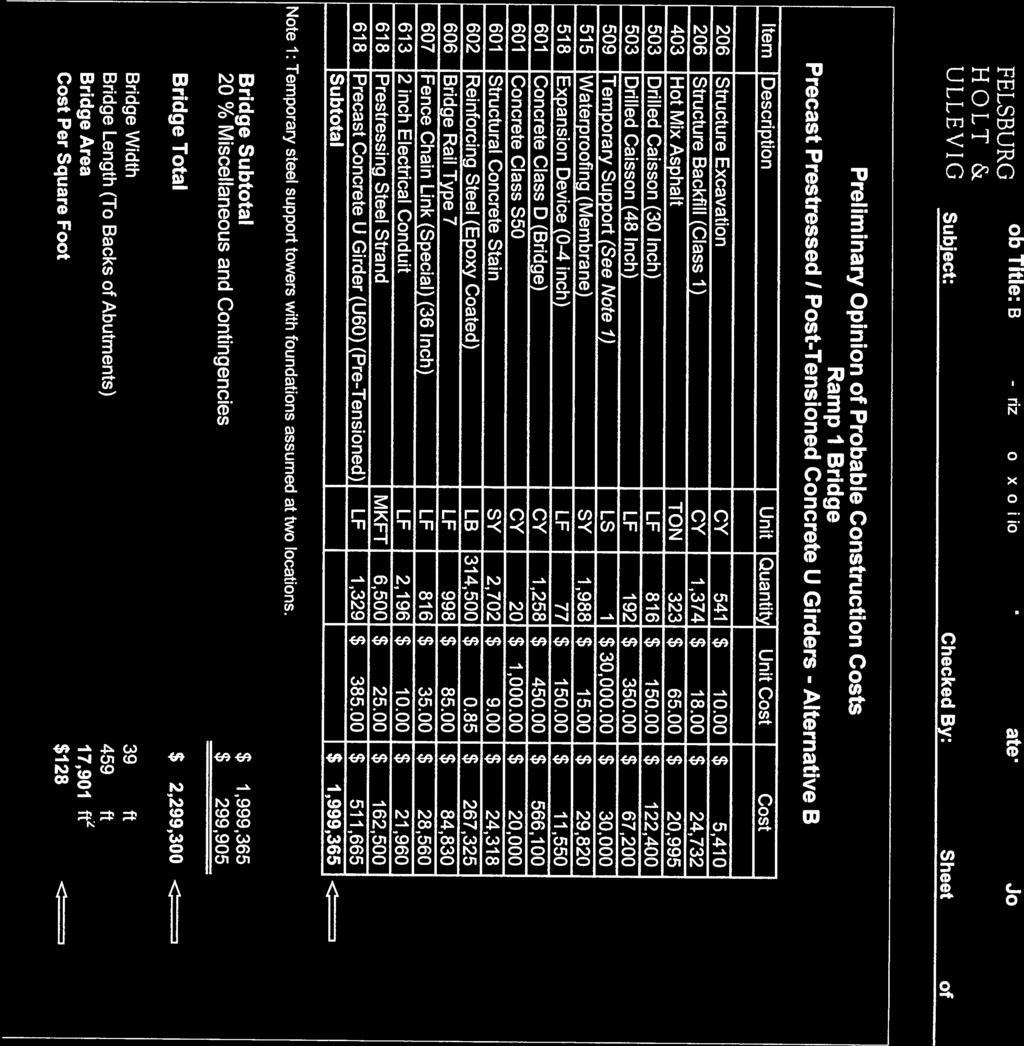
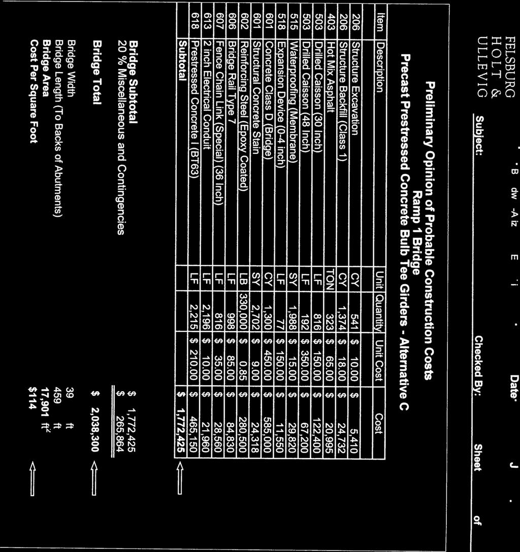
17 City & County of Denver Project No. CE93007 South Broadway Arizona to Exposition & I-25 Interchange Structure Selection Report haunches, will be approximately 6.25 feet. This section is compatible with the proposed Ramp 1 profile. The concrete strengths required for the 125 foot spans are f c initial = 6.0 ksi, and f c final = 7 ksi. Approximately inch diameter low-relaxation strands will be required for the girder design. These requirements are well within the tolerable strength limits for the girder. The controlling factor for the girder design will be the long-term deflections of the girders. The relatively shallow superstructure section will tend to flatten out over time due to prestressing losses and concrete creep effects. The 125 foot span is very near the span limit for the prestressed 60 inch U girders, due to camber and deflection limitations. Spans exceeding 125 feet using 60 inch U girders would need to consider post-tensioning to avoid long-term sagging of the spans. The total bridge construction cost for this alternative is estimated to be $2,055,000, or $115 per square foot. Refer to Appendix B for the Opinion of Probable Construction Cost. For the typical section, refer to Figure 4 in Appendix A. Alternative B: Precast Prestressed/Post-Tensioned Concrete U Girders A four-span alternative using Precast Prestressed/Post-Tensioned Concrete U Girders was considered with spans of 93.5 feet, 142 feet, 135 feet, and 83.5 feet. As noted previously, this span configuration approximately aligns the Pier 2 column in line with the adjacent viaduct pier columns, and Pier 4 with the east viaduct abutment. A minimum of two splices will be required for the post-tensioned superstructure construction, requiring temporary support towers. Placement of these towers in proximity of South Broadway is not desired, so that as much room as possible is kept available for shifting traffic during construction. Placing the splices and towers on the east and west sides of the roadway, not over traffic, would require an expansion joint in the superstructure over the center pier (Pier 3). Expansion joints over piers are discouraged, since they are difficult to maintain and often fail. This puts the pier substructure at risk from the effects of the failed joint. The total bridge construction cost for this alternative is estimated to be $2,300,000, or $128 per square foot. Refer to the Preliminary Opinion of Probably Construction Costs in Appendix B. For the typical section, refer to Figure 4 in Appendix A. Alternative C: Precast Prestressed Concrete Bulb Tee Girders A Precast Prestressed Concrete Bulb Tee Girder structure can be considered for the same span configuration as Alternative A, using essentially the same pier and abutment configurations. The superstructure will have five lines of Precast Prestressed Concrete BT63 girders spaced at 8 feet on-center with an 8 inch concrete deck. The total structure depth of 6.50 feet is estimated, which includes a 3 inch asphalt overlay, and consideration for haunches in the bridge deck near the girder supports. This alternative would require raising the proposed Ramp 1 profile at least 3 inches to maintain 16.5 feet of clearance over South Broadway. The construction cost for this bridge alternative is estimated to be $2,038,000 or $114 per square foot. Refer to the Preliminary Opinion of Probably Construction Costs in Appendix B. For the typical section, refer to Figure 4 in Appendix A. Page 13
18 Bridge Substructure City & County of Denver Project No. CE93007 South Broadway Arizona to Exposition & I-25 Interchange Structure Selection Report The bridge piers will be aligned in a north-south orientation to match the existing I-25 viaduct columns. Pier Caps will be skewed approximately 45 degrees, so that the cap is perpendicular to the superstructure girders. The skewed cap minimizes the cantilever length of the cap off the column, and eliminates the need for expensive post-tensioning needed in longer cap cantilevers. An inverted-t pier cap will be utilized, constructed with typical reinforcing steel. The bottom of the cap will project approximately 30 inches below the bottom of the girders. At the center pier, the skew will set the entire dropped cap section over the center median and will not impact the vertical clearance over the roadway. Another advantage to the skewed, inverted-t cap construction is that it eliminates shoring requirements for alternate types of pier construction, allows for the simplest and quickest girder erection sequence, and assures the least amount of impact to South Broadway traffic during construction. Geology Data According to the preliminary geotechnical investigation, and information attained from the recent I-25 viaduct construction plans, bedrock is estimated to vary between 20 and 25 feet below existing grade at the five proposed bridge supports (2 abutments and 3 piers). Both pile and drilled shaft foundation alternatives, anchored in the bedrock, are applicable. A drilled shaft foundation is recommended at the bridge piers due to economy and constructability. A pile foundation alternative will require at least 12 HP 12x74 piles to provide the same support capacity as 2 48 inch diameter drilled shafts. The total cost to install 12 piles at each pier is estimated to be $22,000, and the cost for two drilled shafts is estimated to be $20,500. The size of the pile cap required will be approximately 20 feet long by 10 feet wide to accommodate the spread of the piles. The cap for the drilled shaft alternative is smaller, at 17.5 feet long by 7 feet wide. Each cap will have approximately the same depth. The smaller cap for the caissons can be constructed within a smaller work area, which will be helpful in moving traffic along South Broadway during construction of the median pier. Since a drill shaft contractor will already be mobilized for the pier foundation construction, drilled shafts are recommended for the abutment foundations. Construction Phasing / Constructability The Precast Prestressed Girder superstructure alternative will allow for conventional construction of the Ramp 1 Bridge. Special construction phasing should not be required, since a majority of the bridge substructure construction is out of the way of traffic, with the exception of the center pier. The center pier construction, however, should be able to be completed without significant interruption to traffic. No shoring will be required for the girder erection. Temporary closures of South Broadway will be required for the girder erection, but will likely be limited to only one or two nights of girder erection activity. The new west bridge abutment will be less than 10 feet away from MSE walls along the existing Southbound I-25 off-ramp on the south side. Excavations for the new bridge construction will need to be limited to maintain the stability of the existing MSE walls. However, shoring or underpinning of the existing walls is not anticipated to be required. Page 14
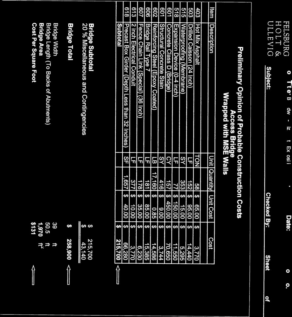
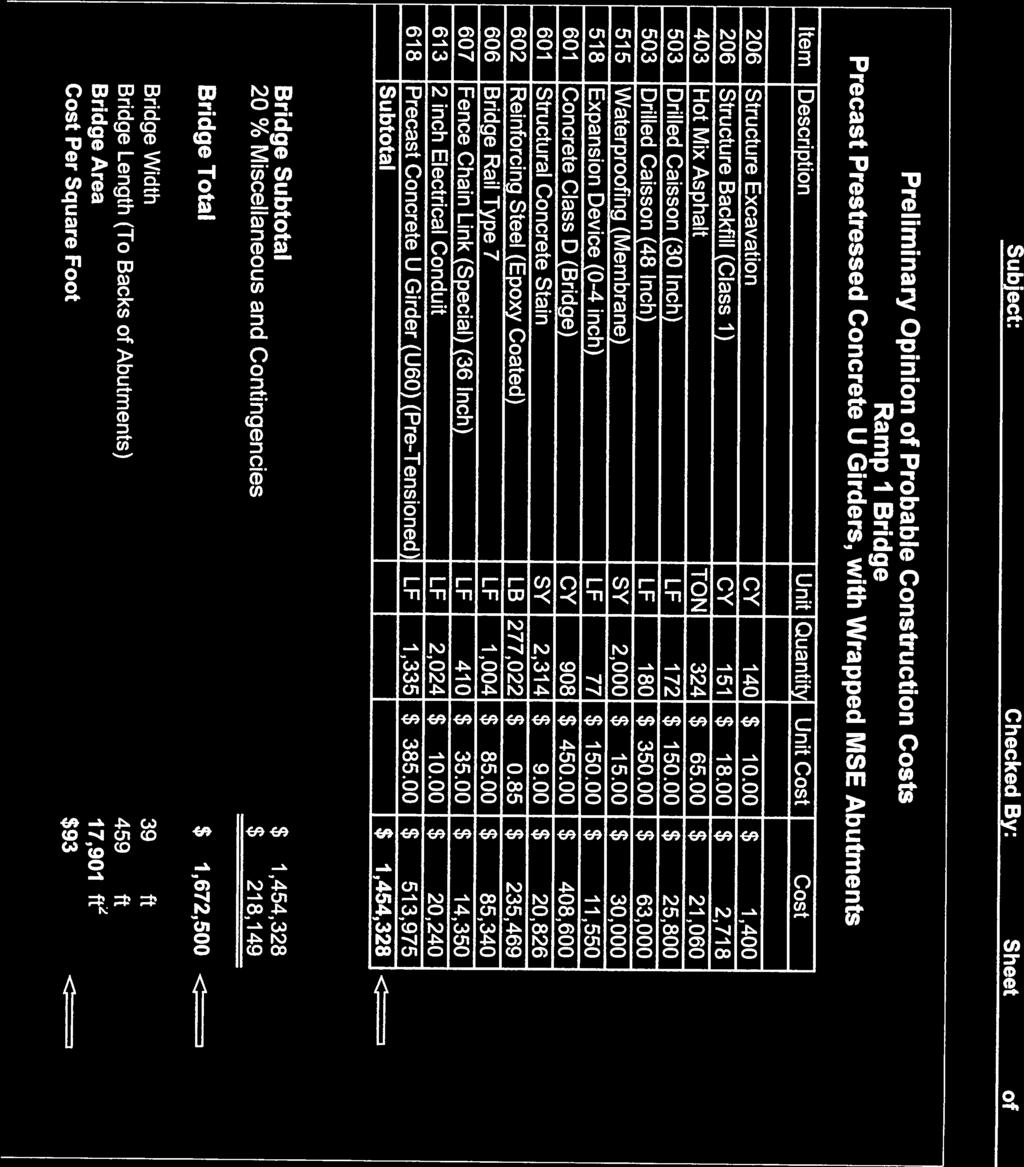
19 City & County of Denver Project No. CE93007 South Broadway Arizona to Exposition & I-25 Interchange Structure Selection Report Drainage / Hydraulic Considerations The Ramp 1 Bridge drainage will flow in both directions from the high point of the bridge, which is centered at South Broadway. The bridge drainage will be captured with deck drains at the front of each bridge abutment, prior to the expansion joint located at the back wall of each abutment, and outlet onto the ground or into the nearest storm drain system below the bridge. There are no other hydraulic or drainage concerns below the bridge. Lighting Requirements Any lighting required beneath the bridge can be accommodated in several locations. Suspending lighting from blow the bridge deck is possible, and lighting mounted to the bridge piers and abutments can be considered. \ The lighting for Ramp 1 will likely be supplied from mid or high mast overhead lighting that will not be attached to the bridge, thus no special mounting details are required. Utilities A fiber optic line that was placed during the recent I-25 viaduct construction is currently aligned beneath the proposed east abutment and center pier locations. The depth of the line is not known. Potholing has been scheduled to verify its exact depth and location at the abutment and pier. Interference is a concern at the center pier foundation, and will require a more in-depth review of the construction options available when the potholing information is available. The line consists of a multiple duct bank, and probably cannot be relocated. However, there may be an opportunity to vertically adjust the elevation of the line at the pier, such that the pier foundation can straddle the line. The fiber optic alignment beneath the east abutment is a lesser concern, since there is more flexibility available for the abutment foundation design than at the pier. An electrical line serving existing traffic signals has been identified near the proposed center pier. It is expected that this line will be relocated or replaced during the new signal installation in proximity of the proposed bridge. An existing storm pipe crosses the proposed west abutment. This pipe will likely be abandoned when the drainage improvements for the project are constructed, and no special design considerations at the abutment are expected. Evaluation and Recommendations A Precast Prestressed Concrete U Girder bridge with tall concrete abutments is recommended as the most viable option for the bridge. It offers the most benefit with respect to cost and constructability, while meeting the geometric and aesthetic requirements for the project. The estimated structure cost is estimated to be $2,055,000, or $115 per square foot. For the typical section, refer to Figure 4 in Appendix A. Refer to the Preliminary Opinion of Probable Construction Cost in Appendix B. A Precast Prestressed Concrete U Girder bridge alternative with stubby abutments and MSE walls wrapped about the abutment has also been provided, for information only, in the Appendix. Page 15
20 City & County of Denver Project No. CE93007 South Broadway Arizona to Exposition & I-25 Interchange Structure Selection Report 6.0 RETAINING WALL EVALUATION 6.1 Ramp 1 and Ramp 2 Walls There will be three areas of retaining wall construction along the length of Ramp 1. West of the Access Bridge, two walls paralleling the ramp are required. Ramp 1 Wall 1A: aligned along the south side of the ramp, 29 feet long, and varies between 11.0 feet and 12.0 feet in height Ramp 1 Wall 1C: aligned on the north side of the ramp, 19.0 feet long, and varies between 8.0 feet and 9.0 feet in height Between the Access Bridge and the Ramp 1 Bridge, two more walls paralleling the ramp are required. Ramp 1 Wall 2A: aligned along the south side of the ramp, feet long, and varies between 15.0 feet and 18.0 feet in height Ramp 1 Wall 2C: aligned along the north side of the ramp, feet long, and varies between 17.0 feet and 20.0 feet in height East of the Ramp 1 Bridge, a wall is aligned along the south side of Ramp 1. Ramp 1 Wall 3B: aligned on the south side of the ramp, feet long, and varies between 14.0 feet and 22.0 feet in height The inside of Ramp 2 will require a retaining wall to allow for the construction of a water quality pond and other landscaping and pedestrian features. Two walls are required to complete the Ramp 2 construction. Ramp 2 Wall 1: aligned along the north side of Ramp 2, feet long, and varies between 8.5 feet and 22.0 feet in height. Ramp 2 Wall 2: aligned along the east side of Ramp 2, adjacent to Ramp 3, feet long, and varies from 6.0 to 13.5 feet in height. Wall Alternatives The Colorado Department of Transportation Bridge Design Manual Subsection No. 5.5 Wall Selection Factors and Procedure lists 24 different retaining walls for consideration. Most of these can be eliminated by inspection, since they are not appropriate for this particular location and project. They can also be dropped from consideration due to expense, geometric constraints, or due to geotechnical considerations. The alternatives most applicable for the Ramp 1 and 2 walls are those that can accommodate economical fill construction, where the construction is primarily above existing grade and minimal cutting of existing grades is required. The two alternatives most suitable for this location are cast-in-place concrete retaining walls on shallow spread footings (CIP), and mechanically stabilized earth walls with precast concrete panel facing (MSE). Page 16
21 City & County of Denver Project No. CE93007 South Broadway Arizona to Exposition & I-25 Interchange Structure Selection Report Several evaluation topics are discussed below, summarizing many of the issues considered in determining the wall type selected for the project. Aesthetics The aesthetic requirements for the project have been discussed previously. Both the MSE and CIP wall alternatives can be finished to meet the demands of the project. The only significant difference in appearance between the systems will be that the MSE panel joints will not be visible in the CIP walls. If desired, the panel pattern can be cast in the CIP walls to match the adjacent existing MSE wall construction, but this could add some expense to the formlined finishing work. Construction Phasing The retaining walls along Ramps 1 will generally be constructed out of the way from existing traffic. At the west end of the Ramp 1, parking for the RTD Broadway Station will need to be configured to allow for the complete wall construction without special phasing. At the east end of Ramp 1, the existing on-ramp from South Broadway to Southbound I-25 will be closed, allowing for wall construction without phasing. The Ramp 2 walls will require the closure of the existing loop ramp onto Northbound I-25 to properly complete the grading and wall construction. Once the ramp is closed, no significant construction phasing in this area should be necessary. Hydraulics A potential hydraulic issue having influence on the wall design will be a water quality pond located in proximity of the Ramp 2 Wall 1. To reduce the potential influence of the pond on the retaining wall, a minimum 10 foot wide graded will be graded in front of the wall to separate the pond from the wall. This will help prevent a saturated condition from developing near the wall foundation, assuring its stability. Geology Data The existing subgrade beneath the Ramp 1 and 2 retaining walls provides substantial bearing capacity for both spread footing and MSE construction. Silty sand and gravelly sand are found throughout the area, which overlays bedrock at depths varying from 18 feet to over 45 feet. The nominal (LRFD ultimate) bearing design capacity recommended for the site is 20,000 psf. This is equivalent to over 11,000 psf in allowable bearing capacity, which is excellent for supporting shallow spread foundation systems. Deep foundations were considered at the west end of Ramp 2 Wall 1 for constructability reasons, due to the close proximity of the new wall to the existing MSE walls along I-25. However, the preliminary geotechnical investigation indicated no bedrock within the first 45 feet of depth at this location. Shallow spread footings will be used for all the Ramp 1 and 2 wall designs, sized and oriented as needed to avoid impacts to the existing MSE walls. Page 17
22 City & County of Denver Project No. CE93007 South Broadway Arizona to Exposition & I-25 Interchange Structure Selection Report Utilities Various utility lines currently exist along the proposed wall alignments, including electrical lines, drainage pipes, fiber-optic conduit, water lines, and gas lines. Most utilities are expected to be abandoned or relocated from the wall construction locations. The few conditions that may require attention for the final Ramp 1 and 2 wall designs include: Ramp 2 Wall 1 : Gas lines and water lines will be removed when the houses they currently serve are also removed. Ramp 2 Wall 2: A new drain pipe is to be placed beneath the wall and the bottom of the wall elevation will need to be coordinated with the top of pipe location, when its elevation is finalized. Ramp 1 Wall 3B: Gas and water lines are currently located under the wall and has not yet been determined whether these will be removed. None of these conditions should complicate the wall construction significantly, or demand special construction. Right-of-Way All of the Ramp 1 retaining walls will be constructed within existing CDOT and City and County of Denver right-of-way. There are no constraints influencing the wall layouts, and no right-of-way will need to be acquired to construct the walls. Right-of-way acquisition is planned where the houses are located along the proposed Ramp 2 alignment. It is anticipated that this whole area will be City and County of Denver property prior to the wall construction, and will not impact any part of the wall construction. Design Life and Proven Performance It is know from a historical basis that reinforced concrete, with an adequate concrete mix design, and proper structural design and construction, is capable of long satisfactory service. Current design may include air entrainment for freeze-thaw resistance, uses of fly ash or silica fume in mixes for reduced permeability, and epoxy coated reinforcing steel for resistance to corrosion. MSE walls are an economical alternative that are designed for a comparable design life as compared to more traditional CIP walls, and other walls systems. Most of the walls have performed well, having been designed and installed by specialty contractors. A concern with the MSE construction has been the natural settlement that occurs within tall wall construction. When adjacent to fixed structures, such as bridges on deep foundations, there have been instances where differential settlement has created a bump or swale a the bridge approaches. This settlement can and should be accounted for the in the design, but there have been instances where it may have been overlooked. The City and County of Denver has expressed its concern in using MSE construction, particularly in taller walls, partly for the reasons explained above. The tallest walls along Ramps 1 and 2 will be approximately 22 feet high, which is not especially tall for MSE wall construction. Some MSE construction in Colorado has approached 40 feet in height. The 22 foot height is Page 18
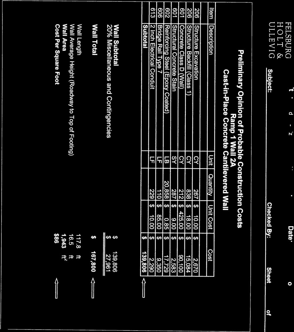
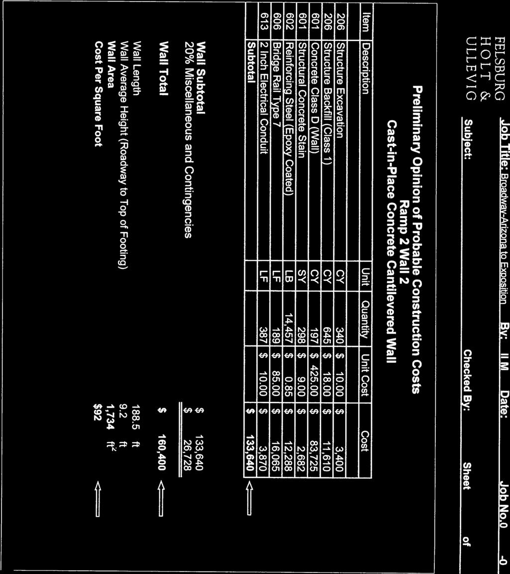
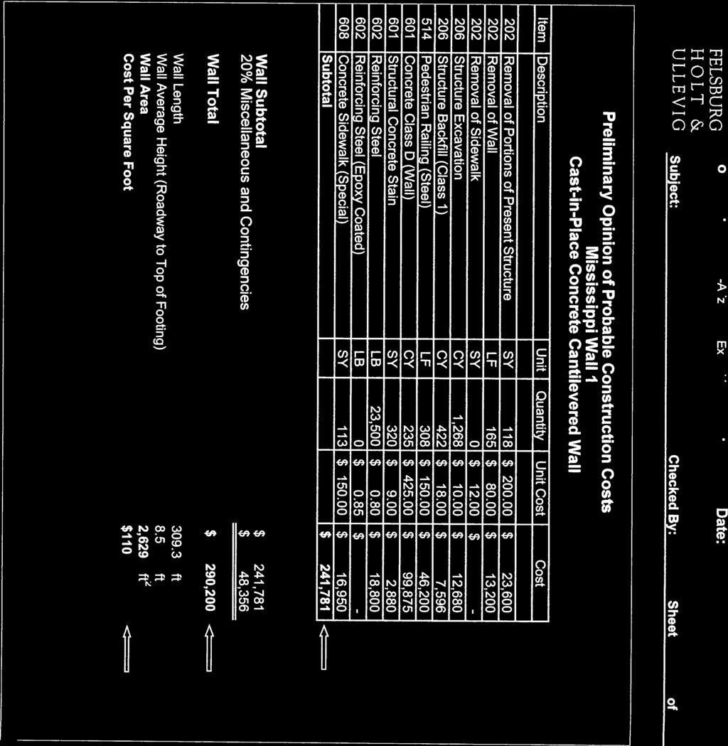
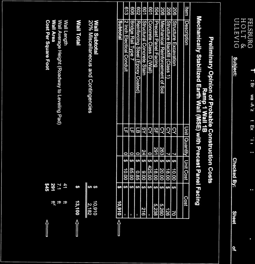
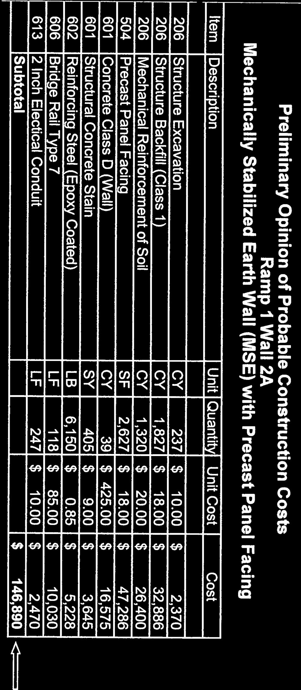
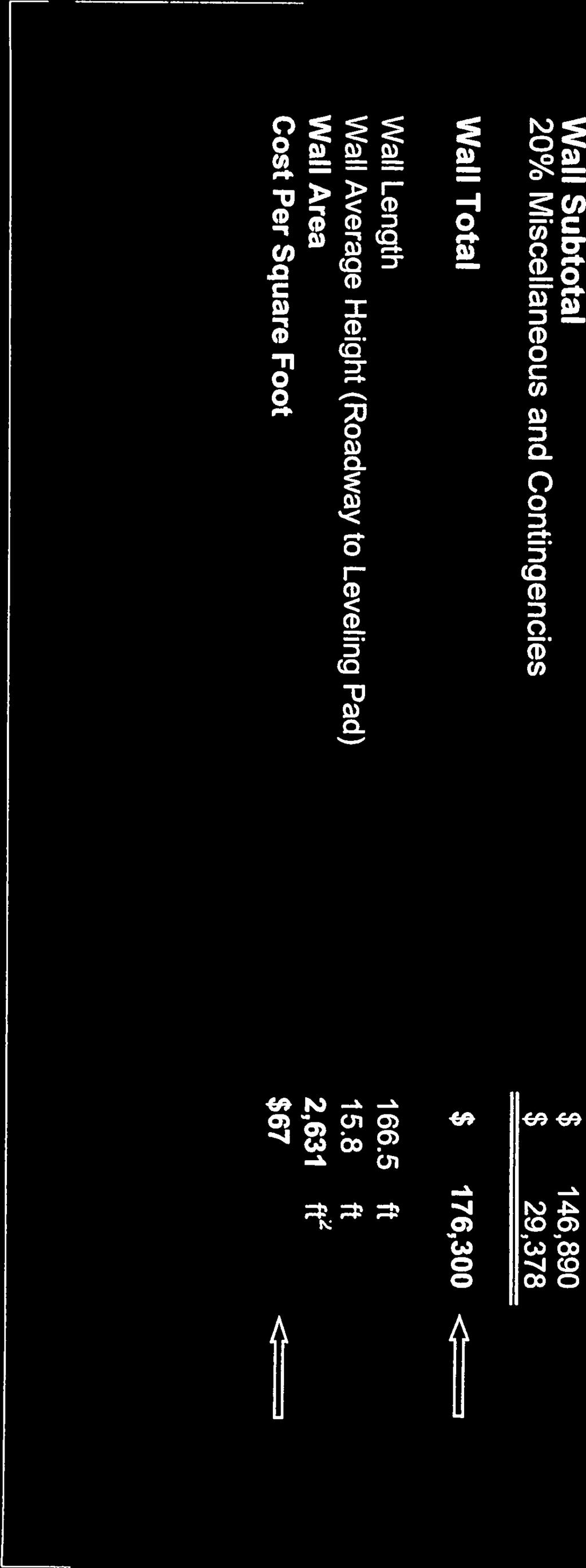
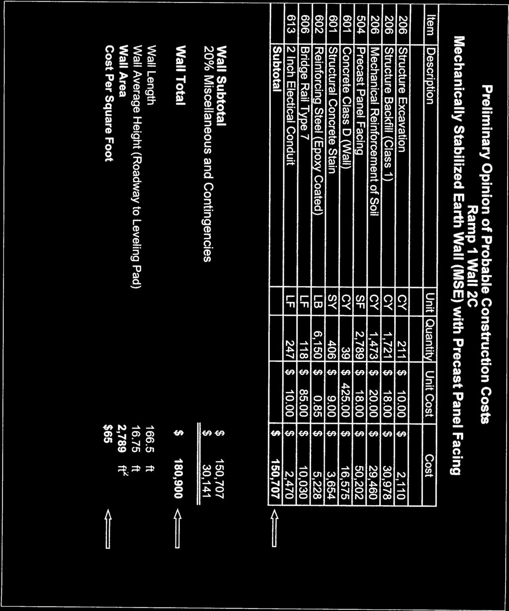
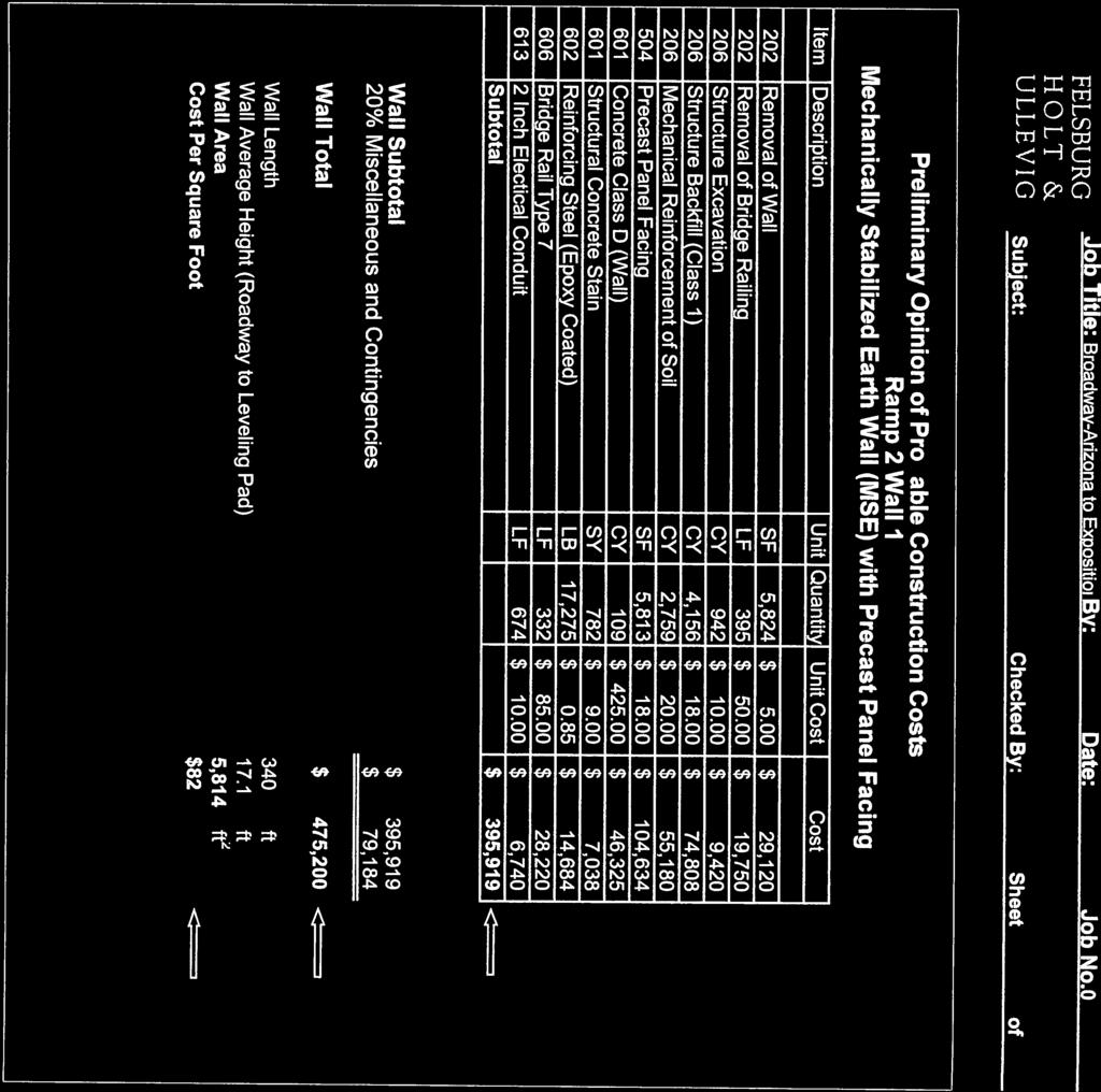
23 City & County of Denver Project No. CE93007 South Broadway Arizona to Exposition & I-25 Interchange Structure Selection Report less common today for CIP construction, but was regularly achieved in the past, with good results. Constructability Both MSE and CIP wall construction would be straightforward along both Ramps 1 and 2. The MSE wall system has an advantage in that its foundation does not have to be as deep (approx. 1.5 feet) as the CIP system (3 feet). This is advantageous when constructing adjacent to existing walls. However, the 3 foot depth required for the CIP system should be attainable without temporary support/shoring of the adjacent walls. MSE wall construction is quite common these days, with many experienced contractors available to complete the work. Well-detailed construction specifications have been established that assure that MSE construction is completed within tight tolerances, providing well-performing structures. CIP wall construction is typically a little more labor intensive than MSE wall construction, and may have a few more constraints, due to the extensive formwork that is required. Construction and schedules can be influenced by the weather conditions, since the concrete curing is influenced by both warm and cold weather. CIP construction schedules can be influenced greatly, as a result. Probable Construction Cost Probable construction costs have been developed for each retaining wall along Ramps 1 and 2, for both MSE and CIP alternatives for comparison. Quantities were estimated for the typical components of each type of wall construction, and include details and items specific to each. Items such as mobilization and construction engineering have not been considered, but all estimates include a 20% additional cost for contingencies. See the Preliminary Opinion of Approximate Cost Summaries in Appendix B. The approximate square foot costs for each system using current cost data are: MSE Retaining Wall with Precast Panel Facing = $67 per square foot CIP Retaining Wall on Shallow Spread Footing Foundation = $90 per square foot Evaluation and Recommendations MSE and CIP wall systems are both viable systems for the Ramp 1 and 2 wall construction. The main differentiator between the systems is cost, where MSE has a significant advantage. Application of the MSE wall system would also benefit the Ramp 1 bridges by simplifying the abutment construction, resulting in reduced bridge costs. The performance of the MSE walls can be addressed during the design and construction phases with some modification to the standard details and material specifications. On a typical CDOT or other federally funded project, our recommendation would be to construct MSE walls. However, understanding the City s concerns with MSE construction, CIP walls are recommended as a suitable alternative. Page 19
24 City & County of Denver Project No. CE93007 South Broadway Arizona to Exposition & I-25 Interchange Structure Selection Report 6.2 Mississippi Avenue Walls Two new parallel walls will be constructed to replace two existing walls west of South Broadway. The replacement walls will accommodate the widening of Mississippi Avenue and the realignment of the existing sidewalk along the north side of Mississippi Avenue. Mississippi Wall 1: aligned along the north side of the re-aligned sidewalk, feet long, and varies between 2.5 feet and 11.0 feet in height Mississippi Wall 2: aligned along the south side of the re-aligned sidewalk, 285 feet long, and varies between 4 feet and 9 feet in height Wall Alternatives The wall construction along the north side of Mississippi Avenue requires cutting into existing grades in proximity of an existing building, and a large waterline. Wall types with construction shoring capacity were initially considered, such as side by side caisson construction. However, this alternative was eliminated early on, as significant obstacles for completing the construction were recognized. The existing retaining walls along Mississippi have large spread footing foundations that made caisson installation impractical. Crossing the waterline was also not feasible along the Mississippi Wall 1 alignment. Sheet pile and nail wall alternatives were also ruled out right away, due to the significant conflicts. Cast-in-place concrete retaining walls on shallow spread footings (CIP) became the most viable solution, primarily due to the construction flexibility concrete offers. It was also recognized that portions of the massive existing walls could remain in place to act as temporary shoring and as part of the final wall construction. The following discussion focuses on the construction challenges remaining in the area using the CIP wall system. Utilities A 24 waterline is located along the proposed horizontal alignment for Mississippi Wall 1. The vertical wall and sidewalk alignment will not adequately clear the pipe where they cross. To accommodate the new wall/sidewalk alignment, a segment of the existing waterline will be lowered and set inside a steel casing. The casing will protect the waterline from the wall and sidewalk loading above. An existing 8 inch sanitary sewer line is aligned approximately 8 feet below the lowest portion of the Mississippi Wall 2 foundation. This line is scheduled to be abandoned prior to the wall construction, thus will not require protection. Construction Phasing While the wall construction will not need any special phasing, traffic control in proximity of the wall construction could be an issue. The existing concrete wall removal effort will be significant, requiring some large equipment. The time required for the removal may be significant, as well, while coordinated with the anticipated water line relocation in this area. Page 20
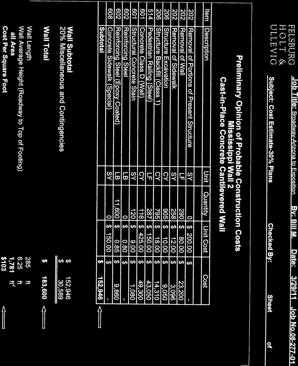
25 City & County of Denver Project No. CE93007 South Broadway Arizona to Exposition & I-25 Interchange Structure Selection Report Hydraulics No significant drainage or hydraulic issues need to be addressed in the wall design and construction in this area. Geology Data The subsurface materials in this area are suitable for spread footing foundations. Gravely sand over claystone bedrock will be located beneath the foundation, which is a similar condition to that discussed in the Ramp 1 and 2 Wall areas. Right-of-Way Mississippi Wall 1 will be constructed entirely within existing City and County of Denver right-ofway. The east end of the wall will be within 3 feet of the right-of-way boundary, but should be able to be constructed without any right-of way takes. The new wall is relatively shallow in this location, and is not expected to require any excavation outside the right-of-way limits. Coordination with the waterline relocation described above will be required to assure the rightof-way limits are not crossed. Mississippi Wall 2 will be constructed entirely within existing City and County of Denver right-ofway, thus there are no constraints influencing the wall layout. Probable Construction Cost Probable construction costs have been developed for the Mississippi Avenue Walls. Quantities were estimated for the recommended construction, including the estimated wall removal requirements to complete the new wall construction. Items such as mobilization, construction engineering, and the waterline relocation have not been included in the costs. All estimates include a 20% additional cost for contingencies. The approximate square foot costs for the walls, using cast-in-place concrete construction on shallow spread footings will be approximately $110 per square foot. The special construction and detailing required through this area, and the relatively small amount of wall construction required has contributed to the higher than typical cost for CIP wall construction. A complete Opinion of Approximate Construction Cost Summary for each wall can be found in Appendix B. Evaluation and Recommendations As noted at the beginning of this section, cast-in-place concrete walls on shallow spread footings are recommended for this location. No other systems provided a practical solution at this location. Page 21
26 APPENDIX A Structure Location Maps and Figures
27
28
29
30
31
32
33

34
35 DESIGN WORKSHOP

36 DESIGN WORKSHOP
37 APPENDIX B Preliminary Opinion of Probable Construction Cost Summaries For Recommended Structures

38 Job Title: Broadway-Arizona to Exposition By: Bill M. Date: 6/27/11 Job No Subject: Cost Estimate-30% Plans Checked By: Sheet of Preliminary Opinion of Probable Construction Costs Access Bridge With Tall Concrete Abutments Item Description Unit Quantity Unit Cost Cost 206 Structure Excavation CY 110 $ $ 1, Structure Backfill (Class 1) CY 718 $ $ 12, Hot Mix Asphalt TON 57 $ $ 3, Drilled Caisson (24 Inch) LF 218 $ $ 20, Waterproofing (Membrane) SY 346 $ $ 5, Expansion Device (0-2 inch) LF 77 $ $ 7, Concrete Class D (Bridge) CY 281 $ $ 126, Structural Concrete Stain SY 416 $ 9.00 $ 3, Reinforcing Steel (Epoxy Coated) LB 17,160 $ 0.85 $ 14, Bridge Rail Type 7 LF 177 $ $ 15, Fence Chain Link (Special) (36 Inch) LF 173 $ $ 6, inch Electrical Conduit LF 394 $ $ 3, Precast Box Girder (Depth Less than 32 Inches) SF 1,622 $ $ 64,880 Subtotal $ 286,029 Bridge Subtotal $ 286, % Miscellaneous and Contingencies $ 57,206 Bridge Total $ 343,300 Bridge Width 39 ft Bridge Length (To Backs of Abutments) 48.5 ft Bridge Area 1,892 ft 2 Cost Per Square Foot $181 1of 1 Access Bridge Tall Abut

39
40
41
42
43
44
45

46
47
48

49
50
51 APPENDIX C Preliminary Opinion of Probable Construction Cost Summaries For Structure Types With MSE Construction (For Information Only)
52


53
54
55
56
57
58
59
60
61
62
63
Chapter 1. General Design Information. Section 1.02 Structure Selection and Geometry. Introduction
 Chapter 1 Bridge Design Manual General Design Information Section 1.02 Selection and Geometry Introduction Selection or Rehabilitation Report This section of the design manual provides guidance on the
SOUTH MEDFORD INTERCHANGE BRIDGES
 Eleven bridges were required for the project THe I-5 south medford Interchange by Keith Kaufman, Knife River Corporation Northwest and Daniel J. McIntier, formerly with H.W. Lochner Inc. Interstate 5 is
Design and Construction of the SH58 Ramp A Flyover Bridge over IH70. Gregg A. Reese, PE, CE, Summit Engineering Group, Inc.
 Design and Construction of the SH58 Ramp A Flyover Bridge over IH70 Gregg A. Reese, PE, CE, Summit Engineering Group, Inc., Littleton, CO ABSTRACT: The SH58 Ramp A bridge in Golden, CO is the latest on
SR 0136-G10 ABC BRIDGE REPLACEMENT in Eighty Four, PA
 ASHE NATIONAL PROJECT OF THE YEAR SR 0136-G10 ABC BRIDGE REPLACEMENT in Eighty Four, PA For the PENNSYLVANIA DEPARTMENT OF TRANSPORTATION Engineering District 12-0 Submitted By: January 29, 2018 AMERICAN
CHAPTER 11: WALLS.
 CHAPTER 11: WALLS MODULAR BLOCK WALL (DRY CAST) Rather than being pre-approved as systems, the components of Modular block walls (dry cast) are pre-approved separately. The approved MBW components are
Structural - Engineering Review Checklist
 Structural - Engineering Review Checklist Project: List Corridor Criteria ID Review Priority (H,M,L) TOPICS S-_-## Structural Design Codes, Manuals and Specifications 6.1.0 REFERENCES DESIRED Criteria
DESIGN OF CAMPBELL ROAD OVERPASS IN KELOWNA. Yulin Gao, M.A.Sc., P.Eng., SNC-Lavalin Inc. Samson Chan, M.Eng., P. Eng., SNC-Lavalin Inc.
 DESIGN OF CAMPBELL ROAD OVERPASS IN KELOWNA Yulin Gao, M.A.Sc., P.Eng., SNC-Lavalin Inc. Samson Chan, M.Eng., P. Eng., SNC-Lavalin Inc. Paper prepared for presentation at the Bridges in a Climate of Change
Conceptual Design Report
 Conceptual Design Report I-244/Arkansas River Multimodal Bridge Tulsa, Oklahoma Prepared for the Oklahoma Department of Transportation Prepared by: August 2009 I-244 / ARKANSAS RIVER MULTIMODAL BRIDGE
APPENDIX C INLETS. The application and types of storm drainage inlets are presented in detail in this Appendix.
 Storm Drainage 13-C-1 APPENDIX C INLETS 1.0 Introduction The application and types of storm drainage inlets are presented in detail in this Appendix. 2.0 Inlet Locations Inlets are required at locations
I-35W Retaining Wall Design Exhibit A - Draft Scope of Work
 Background MnDOT, Metro Transit, Hennepin County, and the City of Minneapolis are in the process of developing a project for Interstate 35W between 43 rd Street in Minneapolis and 15 th Street in Minneapolis.
MICHIGAN DEPARTMENT OF TRANSPORTATION BRIDGE DESIGN GUIDES TABLE OF CONTENTS
 MICHIGAN DEPARTMENT OF TRANSPORTATION BRIDGE DESIGN GUIDES TABLE OF CONTENTS SECTION 1 - MISCELLANEOUS STANDARDS 1.00.01 -.05 Table of Contents 1.11.01 Decimal Parts of a Foot and Inch 1.21.01 Factors
ACHD Bridge and Culvert Policy DRAFT
 ACHD Bridge and Culvert Policy DRAFT Standard Drawings and additional construction details are contained in the separate ACHD Bridge Design Guide and are hereto made part of this policy by reference. DEFINITIONS
STANDARDIZED CONCRETE BRIDGES IN TEXAS. John Holt, PE, Texas Department of Transportation Ronald Medlock, PE, Texas Department of Transportation
 STANDARDIZED CONCRETE BRIDGES IN TEXAS John Holt, PE, Texas Department of Transportation Ronald Medlock, PE, Texas Department of Transportation ABSTRACT Standardized concrete bridge plans are used extensively
SIBLEY POND DESIGN-BUILD BRIDGE REPLACEMENT ROUTE 2 CANAAN/PITTSFIELD, MAINE
 SIBLEY POND DESIGN-BUILD BRIDGE REPLACEMENT ROUTE 2 CANAAN/PITTSFIELD, MAINE Keith Donington, P.E. October 2012 1 Sibley Pond - Bridge Elevation 2 Bridge Open to Traffic November 2011 3 Bridge Highlights
STATE OF NEW JERSEY DEPARTMENT OF TRANSPORTATION
 STATE OF NEW JERSEY DEPARTMENT OF TRANSPORTATION PRELIMINARY DESIGN SUBMISSION REPORT For U.S. Route 130 Over Raccoon Creek Bridge Township of Logan Gloucester County, New Jersey Prepared By: Structural
B R I D G E O F F I C E
 LRFD Bridge Design Manual BRIDGE OFFICE MANUAL 5-392 MINNESOTA DEPARTMENT OF TRANSPORTATION Bridge Office LRFD Bridge Design Manual MnDOT BRIDGE OFFICE LRFD Bridge Design Manual Minnesota Department of
AESTHETIC AND TECHNOLOGICAL CONCEPTS FOR THE NEW ROUTE 9 SOUTHBOUND BRIDGE AND THE REHABILITATION OF THE EDISON BRIDGE
 Over the Raritan River, New Jersey 29 AESTHETIC AND TECHNOLOGICAL CONCEPTS FOR THE NEW ROUTE 9 SOUTHBOUND BRIDGE AND THE REHABILITATION OF THE EDISON BRIDGE After 62 years of service without a major reconstruction,
B R I D G E O F F I C E
 LRFD Bridge Design Manual BRIDGE OFFICE MANUAL 5-392 MINNESOTA DEPARTMENT OF TRANSPORTATION Bridge Office LRFD Bridge Design Manual MnDOT BRIDGE OFFICE LRFD Bridge Design Manual Minnesota Department of
Constructability Guidelines
 Constructability Guidelines The Constructability Guidelines offer a list of items that should be considered by Constructability function personnel during the Concept Development Phase through the Final
PHASING CONSIDERATIONS FOR BRIDGES
 PHASING CONSIDERATIONS FOR BRIDGES Christopher Miller, P.E. 6/11/18 Table of contents 1 What Not to Do 3 2 Span Arrangement 4-9 3 4 5 6 Superstructure Geometric Considerations Superstructure Structural
Presented by: Taya Retterer BRG Webinar July 30, 2012
 Presented by: Taya Retterer BRG Webinar July 30, 2012 PHASED CONSTRUCTION RECOMMENDATIONS FOR BRIDGES Will be posted to the TxDOT Website http://www.dot.state.tx.us/business/contractors_consultants/bridge/default.htm
Review of Plans and Specs from a Constructability Perspective
 Review of Plans and Specs from a Constructability Perspective The Executive Regional Manager and the Project Manager, with approval of the Director of Project Management, may request the Constructability
SINGLE STEEL BOX GIRDER BRIDGES FOR THE TERMINAL DEVELOPMENT PROJECT AT TORONTO PEARSON INTERNATIONAL AIRPORT. Srdjan Brasic, M.Sc., P.Eng.
 SINGLE STEEL BOX GIRDER BRIDGES FOR THE TERMINAL DEVELOPMENT PROJECT AT TORONTO PEARSON INTERNATIONAL AIRPORT Srdjan Brasic, M.Sc., P.Eng. UMA Engineering Ltd. Paper prepared for presentation at the Technical
Bridge and Culvert Design Standards
 3004 ROADWAY DESIGN STANDARDS 3004.1 Roadway Design Roadway planning and design for the public road system shall conform to the following guidelines and referenced specifications. Use the most current
PROJECT UPDATE SOUTH NORFOLK JORDAN BRIDGE CITIES OF PORTSMOUTH AND CHESAPEAKE, VIRGINIA. April 2012
 PROJECT UPDATE Rendering View from the City of Chesapeake Elizabeth River Boat Landing and Park looking across the Elizabeth River at Portsmouth CITIES OF PORTSMOUTH AND CHESAPEAKE, VIRGINIA The new 5,375
LRFD Bridge Design Manual Changes
 LRFD Bridge Design Manual Changes Dave Dahlberg Bridge Design Manual & Policy Engineer May 17, 2017 Bridge Office mndot.gov/bridge Overview 1) Concrete mix designations 2) Reinforcing bar development and
Ironton Russell Bridge Project
 Construction Update January 1, 2016 Rendering by URS Responsible for Construction Inspection & Engineering Prepared by: Brian Davidson, P.E. Project Overview The Ironton Russell Bridge Project entails
NORFOLK SOUTHERN RAILWAY COMPANY FILES: BR & BR
 NORFOLK SOUTHERN RAILWAY COMPANY FILES: BR0013844 & BR0013129 COLUMBIA, CHEROKEE COUNTY, SOUTH CAROLINA I-85 UNDERPASS PROJECT (1) REPLACEMENT OF EXISTING I-85 UNDERPASS BRIDGE MILEPOST SB-141.35 DOT/AAR
Grade-Separated Trail Crossings How Do We Get Over There?
 Grade-Separated Trail Crossings How Do We Get Over There? 2008 National Trails Symposium Rory Renfro, Alta Planning + Design Scott Belonger, Loris and Associates Peter Loris, Loris and Associates PRESENTATION
JULY 2016 LRFD BRIDGE DESIGN 11-1
 JULY 016 LRFD BRIDGE DESIGN 11-1 11. ABUTMENTS, PIERS, AND WALLS This section contains guidance for the design and detailing of abutments, piers, retaining walls, and noise walls. Abutments and piers are
VT 14 East Montpelier Bridge Project Informational Meeting. February 22, 2017
 VT 14 East Montpelier Bridge Project Informational Meeting February 22, 2017 Welcome & Introductions VTrans Mark Sargent, Project Manager Wayne Symonds, Structures Program Manager Chris Barker, Resident
Railroad Technical Memorandum for the North Meadows Extension to US 85 and Interstate 25
 for the North Meadows Extension to US 85 and Interstate 25 March 2010 Prepared for: Town of Castle Rock Douglas County Colorado Department of Transportation Federal Highway Administration Prepared by:
Traffic Technical Memorandum: Hickman Road over Tuolumne River Bridge Replacement Project, Stanislaus County (BRLO-5938(199))
)") 11060 White Rock Road, Suite 200 Rancho Cordova, CA 95670 Phone: (916) 363-4210 Fax: (916) 363-4230 M e m o r a n d u m To: Reena Gohil, Environmental Planner Date: May 30, 2017 California Department of
11060 White Rock Road, Suite 200 Rancho Cordova, CA 95670 Phone: (916) 363-4210 Fax: (916) 363-4230 M e m o r a n d u m To: Reena Gohil, Environmental Planner Date: May 30, 2017 California Department of
The Chief Estimator Software. Item Cost Summary Bridge & Overpass Projects
 The Chief Estimator Software Item Cost Summary Bridge & Overpass Projects Elevated Transit Guideways Precast Girder Elevated Guideway 10 Abutment Excavation & Backfill 1,500.00 m3 222 10,368 8,634 1,309
Welcome and thank you for spending time with us today to talk about the 75 th Street Corridor Improvement Project.
 1 Welcome and thank you for spending time with us today to talk about the 75 th Street Corridor Improvement Project. 2 During this public meeting, we will explain the 75 th Street Corridor Improvement
Construction Cost Estimation Preparation Manual for Preliminary Design (English Units)
") 10/16/2014 Construction Cost Estimation Preparation Manual for Preliminary Design (English Units) July 2002 Prepared by Construction Cost Estimating Unit Program Support Services 10/16/2014 Table of Contents
10/16/2014 Construction Cost Estimation Preparation Manual for Preliminary Design (English Units) July 2002 Prepared by Construction Cost Estimating Unit Program Support Services 10/16/2014 Table of Contents
CHECKLIST FOR STREETS, INLETS, AND STORM SEWER DESIGN
 CHECKLIST FOR STREETS, INLETS, I. STREET CLASSIFICATION AND DESIGN CRITERIA A. Determine drainage classification for the roadway section using Table 7-1 or Table 7-2. B. Determine the allowable flow depth
St. Anthony Falls I-35W Bridge Replacement. ASHE National Conference June 13, Dustin Thomas, P.E. I-35W Bridge Construction Engineer
 St. Anthony Falls I-35W Bridge Replacement ASHE National Conference June 13, 2014 Dustin Thomas, P.E. I-35W Bridge Construction Engineer The Former Bridge - 9340 Opened to traffic in 1967 Steel truss bridge
SPECIAL PROVISION Description of Project, Scope of Contract, and Sequence of Work
 2004 Specifications CSJ: 0932-01-076 SPECIAL PROVISION Description of Project, Scope of Contract, and Sequence of Work 1.0 Description of Project 1.1. General. This project provides for the widening of
OHIO DEPARTMENT OF TRANSPORTATION CENTRAL OFFICE, 1980 W. BROAD ST., COLUMBUS, OHIO
 OHIO DEPARTMENT OF TRANSPORTATION CENTRAL OFFICE, 1980 W. BROAD ST., COLUMBUS, OHIO 43216-0899 January 20, 2012 To: Users of the Bridge Design Manual From: Tim Keller, Administrator, Office of Structural
ENGINEERING DIRECTIVE
 Number: E-95-001 Date: 2/2/95 ENGINEERING DIRECTIVE Ross B. Dindio (Signature on Original) CHIEF ENGINEER The purpose of this engineering directive is to formally notify ALL Department engineering personnel
Table of Contents. July
 Table of Contents 36.1 General... 3 36.1.1 Bridge or Culvert... 3 36.1.2 Box Culvert Size Restrictions... 4 36.1.3 Stage Construction for Box Culverts... 4 36.2 Dead Loads and Earth Pressure... 5 36.3
NORFOLK SOUTHERN CORPORATION UNDERPASS GRADE SEPARATION DESIGN CRITERIA
 NORFOLK SOUTHERN CORPORATION UNDERPASS GRADE SEPARATION DESIGN CRITERIA PURPOSE AND SCOPE These criteria modify and supplement the applicable sections of the AREMA Manual of Recommended Practice in connection
DESIGN AND CONSTRUCTION OF DERRY ROAD AND CANADIAN NATIONAL RAIL GRADE SEPARATION
 DESIGN AND CONSTRUCTION OF DERRY ROAD AND CANADIAN NATIONAL RAIL GRADE SEPARATION Vireak Hinh, P.Eng. R.V. Anderson Associates Ltd., Toronto, Canada Jennifer Trimble Region of Halton, Oakville, Canada
Plessis Road Twinning and Grade Separation at CN Redditt Subdivision: Design Challenges and Innovative Solutions
 Plessis Road Twinning and Grade Separation at CN Redditt Subdivision: Design Challenges and Innovative Solutions Tanya D. Worms, P.Eng. M.Sc., Project Manager, M.D. Steele Construction Ltd. Paper prepared
Ironton Russell Bridge Project
 Construction Update October 1, 2015 Rendering by URS Responsible for Construction Inspection & Engineering Prepared by: Brian Davidson, P.E. Ironton Russell Bridge Project Project Summary: October 1, 2015
2016 ACEC/PA ANNUAL MEETING
 2016 ACEC/PA ANNUAL MEETING z I-49 North, Segment K (I-220 to Martin Luther King Drive) Interchange Project Durk Krone, P.E., TRC Engineers Inc., Baton Rouge, La 1 I-49 North Segment K Project 2 AGENDA
Ironton Russell Bridge Project
 Construction Update September 1, 2014 Rendering by URS Responsible for Construction Inspection & Engineering Prepared by: Brian Davidson, P.E. Ironton Russell Bridge Project Project Summary: September
 Civil and Structural Engineering CONSTRUCTION OF BRIDGE STRUCTURES SHALL BE IN ACCORDANCE WITH THE FOLLOWING SPECIFICATIONS, LISTED IN ORDER OF PRECEDENCE: 1. CDOT STANDARD SPECIFICATIONS FOR ROAD AND
Steve Haines, P.E., Parsons, (303) , James Studer, Kiewit, (926) ,
 , James Studer, Kiewit, (926) ,") PLACEMENT OF PRECAST PRESTRESSED CONCRETE GIRDER BRIDGE SPANS WITH SELF PROPELLED MODULAR TRANSPORTERS PIONEER CROSSING DESIGN/BUILD PROJECT, AMERICAN FORK, UT Steve Haines, P.E., Parsons, (303) 831-8100,
PLACEMENT OF PRECAST PRESTRESSED CONCRETE GIRDER BRIDGE SPANS WITH SELF PROPELLED MODULAR TRANSPORTERS PIONEER CROSSING DESIGN/BUILD PROJECT, AMERICAN FORK, UT Steve Haines, P.E., Parsons, (303) 831-8100,
MOA Project # Golden View Drive Intersection & Safety Upgrades
 Appropriate transitions can include extending the insulation beyond the roadway improvements, reducing the insulation thickness, or angling the insulation downward. Use of a frost tolerant section, an
Guidelines for Checking Final Design Bridge Plans
 MNDOT BRIDGE OFFICE Guidelines for Checking Final Design Bridge Plans Edited by the MnDOT Bridge Office ES ESS Committee February 2018 Disclaimer: This document is meant to be used as a checklist for the
Ironton Russell Bridge Project
 Construction Update March 1, 2014 Rendering by URS Responsible for Construction Inspection & Engineering Prepared by: Brian Davidson, P.E. Ironton Russell Bridge Project Project Summary: March 1, 2014
Rt. 29 Solutions Project Delivery Advisory Panel. February 18, 2016
 Rt. 29 Solutions Project Delivery Advisory Panel February 18, 2016 Agenda item 1: Introductions Project Delivery Advisory Panel Technical Team 2 Agenda item 2: Interaction and Feedback Live Streaming Feb
SECTION GENERAL EXCAVATION
 02210-1 of 11 SECTION 02210 GENERAL EXCAVATION 02210.01 GENERAL A. Description 1. General excavation shall include but not necessarily be limited to, excavation and grading for general site work, roadways,
CHAPTER 3 SCOPE SUMMARY
 CHAPTER 3 SCOPE SUMMARY GENERAL The SDDOT is an active member of AASHTO to share common national design standards for the state highway system. The AASHTO Task Force on Geometric Design has completed the
OHIO DEPARTMENT OF TRANSPORTATION CENTRAL OFFICE, 1980 W. BROAD ST., COLUMBUS, OHIO
 OHIO DEPARTMENT OF TRANSPORTATION CENTRAL OFFICE, 1980 W. BROAD ST., COLUMBUS, OHIO 43216-0899 July 17, 2015 To: Users of the Bridge Design Manual From: Tim Keller, Administrator, Office of Structural
Cleveland Opportunity Corridor Project Section 3. Subcontractor Informational Meeting August 12, 2016
 Cleveland Opportunity Corridor Project Section 3 Subcontractor Informational Meeting August 12, 2016 Agenda Welcome and Opening Remarks Project Overview Prequalifications & Work Types Procurement Overview
Lesner Bridge Replacement
 Lesner Bridge Replacement Rendering of the Completed Lesner Bridge Structure Construction Camera A Construction Camera has been installed to view images of the bridge construction. Images are updated on
CHAPTER 12 INSTALLATION OF UTILITIES AND OTHER SYSTEMS TABLE OF CONTENTS
 CHAPTER 12 INSTALLATION OF UTILITIES AND OTHER SYSTEMS TABLE OF CONTENTS Section Title Page 12.1 General... 12-1 12.2 Design Standards... 12-1 12.2.1 General Requirements...12-1 12.2.2 Minimum Depth...12-1
OHIO DEPARTMENT OF TRANSPORTATION CENTRAL OFFICE, 1980 W. BROAD ST., COLUMBUS, OHIO
 OHIO DEPARTMENT OF TRANSPORTATION CENTRAL OFFICE, 1980 W. BROAD ST., COLUMBUS, OHIO 43216-0899 July 20, 2018 To: Users of the Bridge Design Manual From: Tim Keller, Administrator, Office of Structural
FEBRUARY 2019 LRFD BRIDGE DESIGN 5-1
 FEBRUARY 2019 LRFD BRIDGE DESIGN 5-1 5. CONCRETE STRUCTURES Reinforced and prestressed concrete are used extensively in bridge projects. In addition to general design guidance and information on detailing
3.6 Construction Methods
 Exhibit 144: Birchmount Stop Layout West Don River Bridge - Girders are adequate to accommodate LRT right-of-way and required deck widening. Supplementary support or deck strengthening may be required
Specification Changes and Their Effect on Plans. Bridge Construction Issues. BRG VTC April, 2010
 Specification Changes and Their Effect on Plans Bridge Construction Issues BRG VTC April, 2010 Brian D. Merrill, P.E. BRG Construction & Maintenance Branch Also: Common Plan Review Items Revised Specifications
Bridge Construction. Nick Haltvick North Region Bridge Construction Engineer May 17, Bridge Office mndot.gov/bridge/construction.
 Bridge Construction Nick Haltvick North Region Bridge Construction Engineer May 17, 2017 Bridge Office mndot.gov/bridge/construction.html Topics Bridge Construction Unit Special Provisions Update Bridge
Tilikum Crossing Transit Bridge. Portland, OR
 Tilikum Crossing Transit Bridge Portland, OR Technical Information Size of Project: The Tilikum Crossing Transit Bridge is 1,720 ft. long and required 24,000 cy total concrete Strength Requirements: The
JULY 2014 LRFD BRIDGE DESIGN 5-1
 JULY 014 LRFD BRIDGE DESIGN 5-1 5. CONCRETE STRUCTURES Reinforced and prestressed concrete are used extensively in bridge projects. In addition to general design guidance and information on detailing practices,
EXISTING ROADWAY CONDITION ASSESSMENT REPORT (ERCAR) SAMPLE OUTLINE
 SAMPLE OUTLINE") EXISTING ROADWAY CONDITION ASSESSMENT REPORT (ERCAR) SAMPLE OUTLINE The Existing Roadway Condition Assessment Report (ERCAR) should include the evaluation of all elements against new construction criteria.
EXISTING ROADWAY CONDITION ASSESSMENT REPORT (ERCAR) SAMPLE OUTLINE The Existing Roadway Condition Assessment Report (ERCAR) should include the evaluation of all elements against new construction criteria.
Ironton Russell Bridge Project
 Construction Update October 1, 2014 Rendering by URS Responsible for Construction Inspection & Engineering Prepared by: Brian Davidson, P.E. Ironton Russell Bridge Project Project Summary: October 1, 2014
Rapid City, SD HDR Project No RE: Replacement of Existing I-190 Twin Bridges at I-190/Silver Street Interchange, Rapid City, SD
 To: Steve Gramm, SDDOT Memo From: HDR Project: SDDOT I-190 Silver Street Interchange Study Rapid City, SD HDR Project No. 000000000137390 Date: December 27, 2011 RE: Replacement of Existing I-190 Twin
B STEEL BEAM GUIDE RAIL - OPSS 721
 B721-2 - - OPSS 721 721-2.1 GENERAL Design guidance and a description of Steel Beam Guide Rail systems, including various types and treatments, are provided in the Roadside Design Manual (RDM). 721-2.2
SPECIAL SPECIFICATION 4584 Segmental Concrete Bridge Unit
 2004 Specifications CSJ: 0028-09-111 SPECIAL SPECIFICATION 4584 Segmental Concrete Bridge Unit 1. Description. Construct cast-in-place segmental concrete box girder superstructure according to the plans,
I-74 over the Mississippi River
 I-74 over the Mississippi River Design and Construction of Arch Foundations 104 th Transportation and Highway Engineering Conference Presented by: Andrew J. Keaschall, PE, SE, Alfred Benesch & Company
RESILIENT INFRASTRUCTURE June 1 4, 2016
 RESILIENT INFRASTRUCTURE June 1 4, 2016 WESTMINSTER DRIVE UNDERPASS ACCELERATED BRIDGE CONSTRUCTION USING GIGO (GET IN-GET OUT) BRIDGE CONCEPT Mark D Andrea, M.Sc., P.Eng. Stantec Consulting Ltd., Canada
CONSTRUCTION PLAN CHECKLIST
 CONSTRUCTION PLAN CHECKLIST The design engineer is responsible for ensuring that plans submitted for city review are in accordance with this checklist. It is requested that the executed checklist be submitted
Urban Second Level Bridges Built with Precast Segmental Construction
 28 TRANSPORTATION RESEARCH RECORD 1290 Urban Second Level Bridges Built with Precast Segmental Construction JOHN A. CORVEN Transportation facilities In most major urban areas in the United States are operating
STRUCTURES INSPECTION CERTIFICATION TRAINING COURSE
 STRUCTURES INSPECTION CERTIFICATION TRAINING COURSE Code Pre/Route AFE Function Part 0 1000 7116 1174 N Hadley Eisenbeisz Bridge Construction Engineer Rick Brandner Mitchell Area Darrell utter Assistant
Pattullo Bridge Replacement Project. Cost Report
 Pattullo Bridge Replacement Project Cost Report January 2018 Cost Report Page i TABLE OF CONTENTS 1 PURPOSE... 1 2 BASIS FOR THE ESTIMATE... 2 2.1 Scope of the Works... 2 2.2 Scope of Capital Costs...
ARGENTINE CONNECTION BRIDGE TRIPLE TRACK CROSSING. Kansas City Terminal Railway Company
 James P. Hyland Page 1 ARGENTINE CONNECTION BRIDGE TRIPLE TRACK CROSSING Kansas City Terminal Railway Company James P. Hyland, P.E. Senior Bridge Engineer TranSystems Corporation James P. Hyland Page 2
SCCRTC- MP San Lorenzo River Bridge Walkway Widening Feasibility Report
 SCCRTC- MP 19.43 San Lorenzo River Bridge Walkway Widening Feasibility Report May 19, 2016 INTRODUCTION Jacobs Engineering Group was selected to provide a feasibility report for the Santa Cruz County Regional
Preliminary Engineering Report. For the. Foxglove Trail. Prepared for: The City of Moore. Prepared By:
 Preliminary Engineering Report For the Foxglove Trail Prepared for: The City of Moore Prepared By: Certificate of Authorization No. CA#5714 Expires June 30, 2016 CE Project #264 May 2016 City of Moore
Baseline Document Change Announcement
 New Jersey Department of Transportation 1035 Parkway Avenue, PO Box 600, Trenton, New Jersey 08625-0600 Baseline Document Change Announcement Revisions to NJDOT Design Manual for Bridges and Structures,
SCHEDULE THREE TECHNICAL PROPOSAL SUBMISSION REQUIREMENTS
 SCHEDULE THREE TECHNICAL PROPOSAL SUBMISSION REQUIREMENTS Each Technical Proposal (Volume A of Package 2 of the Proposal) should address each of the items and requests for information described in this
CONCRETE TECHNOLOGY CORPORATION
 PRECAST, PRESTRESSED HOLLOW CORE SLABS DESIGN CRITERIA & SPAN-LOAD CHARTS Introduction 2 Design Criteria for Development of the Span-Load Charts 2 Related Publications 3 Manufacturing Tolerances 4 8" Bare
CHAPTER 12 BRIDGE DECK DRAINAGE SYSTEMS
 OFFICE OF STRUCTURES MANUAL FOR HYDROLOGIC AND HYDRAULIC DESIGN CHAPTER 12 BRIDGE DECK DRAINAGE SYSTEMS APRIL 2011 APRIL 2011 Page 1 Chapter Table of Contents 12.1 Policy... 12-3 12.1.1 Table 1... 12-3
STRUCTURE AND BRIDGE DIVISION
 VIRGINIA DEPARTMENT OF TRANSPORTATION STRUCTURE AND BRIDGE DIVISION INSTRUCTIONAL AND INFORMATIONAL MEMORANDUM GENERAL SUBJECT: VDOT Modifications to the AASHTO LRFD Bridge Design Specifications, 8 th
Red Wing Bridge Alternates
 Alternate 1 Tied Arch Alternate 2 Simple Span Truss Alternate 1 Design Drawing Alternate 2 Design Drawing Similar Bridge Design to Alternate 1 Similar Bridge Design to Alternate 2 Evaluation Matrix for
Ironton Russell Bridge Project
 Construction Update July 1, 2015 Rendering by URS Responsible for Construction Inspection & Engineering Prepared by: Brian Davidson, P.E. Project Overview The entails the construction of a cast in place
MANUAL OF THE STRUCTURE AND BRIDGE DIVISION
 MANUAL OF THE STRUCTURE AND BRIDGE DIVISION DESIGN AIDS AND TYPICAL DETAILS VIRGINIA DEPARTMENT OF TRANSPORTATION VDOT GOVERNANCE DOCUMENT VDOT Manual of the Structure and Bridge Division: Part 02: Design
January 2015 v 2.0. (Revised April 2016)
") v 2.0 (Revised April 2016) Page intentionally left blank. Contents Chapter 2 Bridge Selection 2.1 General 2.1-1 2.1.1 General 2.1-1 2.1.2 Bridge Terms 2.1-1 2.2 Guidelines for Bridge Site Visits 2.2-1
v 2.0 (Revised April 2016) Page intentionally left blank. Contents Chapter 2 Bridge Selection 2.1 General 2.1-1 2.1.1 General 2.1-1 2.1.2 Bridge Terms 2.1-1 2.2 Guidelines for Bridge Site Visits 2.2-1
USE OF HIGH PERFORMANCE STEEL IN TEXAS BRIDGES
 David P. Hohmann, P.E., and John M. Holt, P.E. 1 USE OF HIGH PERFORMANCE STEEL IN TEXAS BRIDGES Submission Date: July 31, 2002 Word Count: 2529 David P. Hohmann, P.E. Director, Bridge Design Branch Bridge
Baseline Document Change Announcement
 BDC16MB-01 Page 1 of 9 New Jersey Department of Transportation 1035 Parkway Avenue, PO Box 600, Trenton, New Jersey 08625-0600 Baseline Document Change Announcement ANOUNCEMENT: BDC16MB-01 DATE: October
CONSTRUCTION SPECIFICATION FOR CONCRETE BARRIERS
 ONTARIO PROVINCIAL STANDARD SPECIFICATION METRIC OPSS 553 FEBRUARY 1991 CONSTRUCTION SPECIFICATION FOR CONCRETE BARRIERS 553.01 SCOPE 553.02 REFERENCES 553.03 DEFINITIONS TABLE OF CONTENTS 553.04 SUBMISSION
APPENDIX D STRUCTURAL REPORT
 Toronto Transit Commission / City of Toronto SCARBOROUGH-MALVERN LIGHT RAIL TRANSIT TRANSIT PROJECT ASSESSMENT STUDY ENVIRONMENTAL PROJECT REPORT APPENDICES APPENDIX D STRUCTURAL REPORT IBI Group Scarborough
SECTION 14 - RESTORATION OF SURFACES TABLE OF CONTENTS
 SECTION 14 - RESTORATION OF SURFACES TABLE OF CONTENTS Section Page SECTION 14 RESTORATION OF SURFACES... 14.1 14-1 GENERAL... 14.1 14-2 PRIVATE ROADS... 14.1 14-3 STREETS AND PARKING LOTS... 14.1 14-3.01
TABLE OF CONTENTS. Section / Article Page
 As of Jan 2015: Minimum temporary vertical clearance 21' 6" Minimum permanent vertical clearance 23' 4" TABLE OF CONTENTS Section / Article Page 1. INTRODUCTION 1.1 Purpose................ 6 1.2 Definitions................
Carpinteria Avenue Bridge Replacement Project Description Introduction
 Carpinteria Avenue Bridge Replacement Project Description Introduction The City of Carpinteria is proposing to replace the existing Carpinteria Avenue Bridge over Carpinteria Creek (Br. No. 51C 0172) with
The Most Advanced Name in Water Management Solutions TM. The most cost-effective slotted and trench surface drain systems.
 The Most Advanced Name in Water Management Solutions TM The most cost-effective slotted and trench surface drain systems. A sensible alternative to metal and concrete Since 1987, Duraslot surface drains
Final Estimates Level 2
 Florida Department of TRANSPORTATION Final Estimates Level 2 Module 6: Structures 11/1/2017 FDOT Final Estimates Level 2 Release 11, Module 6 1 6-1 Module Content Concrete Structures Bridges Substructure
SPECIFICATIONS FOR PRECAST MODULAR BLOCK RETAINING WALL SYSTEM (revised 5/8/7)
") Page 1 of 7 STONE STRONG SYSTEMS SPECIFICATIONS FOR PRECAST MODULAR BLOCK RETAINING WALL SYSTEM (revised 5/8/7) PART 1: GENERAL 1.01 Description A. Work includes furnishing and installing precast modular
Page 1 of 7 STONE STRONG SYSTEMS SPECIFICATIONS FOR PRECAST MODULAR BLOCK RETAINING WALL SYSTEM (revised 5/8/7) PART 1: GENERAL 1.01 Description A. Work includes furnishing and installing precast modular