MDOT Camelback Bridge Example
|
|
|
- Conrad Sharp
- 5 years ago
- Views:
Transcription
1 MDOT Camelback Bridge Example AASHTOWare Bridge Rating July 8, 2013 Contents MDOT Camelback Bridge Example AASHTOWare Bridge Rating Background... 2 Assumptions/Limitations... 2 General Bridge Information... 3 Material Properties... 4 Superstructure Definition... 6 Load Case Descriptions... 8 Framing Plan Details... 9 Typical Section Shear Reinforcement Member Descriptions Cross Sections Bridge Alternatives Analysis Vehicle Selection Analysis Reporting This tutorial was created on behalf of MDOT by the Center for Technology & Training, please contact loadrating@mtu.edu for assistance or visit for more information. 1
2 Background What follows is a general guide for modeling a camelback bridge in AASHTOWare Bridge Rating (BR) The sample bridge was taken from a set of MDOT standard plans for a 60-ft reinforced concrete girder with a 22-ft roadway. A similar approach can be applied to other standard lengths. The tutorial methodology should be adapted accordingly for any modifications to the standard plan and for the specific rebar present in the bridge. This tutorial is being provided by the Michigan Department of Transportation (herein referred to as MDOT) as a courtesy service to contractors, consultants and local agency bridge owners. In preparation of this tutorial, MDOT has endeavored to offer current, correct and clearly expressed information. However, error may occur. MDOT expressly disclaims any liability, of any kind, for any reason, that might arise out of the use of this tutorial. Assumptions/Limitations This tutorial is prepared based on the assumption that the bridge is in a pristine, un-deteriorated state and was built in accordance with the construction plans. All load ratings must reflect the current condition of the structure. The load rating engineer should perform a field evaluation to confirm the correctness of the plans and use engineering judgment to determine whether any observed deterioration may affect the structural capacity of the bridge. In a more traditional girder arrangement the compression zone of each girder is laterally braced by the bridge deck. The camelback bridge design results in an un-braced compression zone. This situation is not addressed by BR Should there be evidence of distress in the compression zone of a camelback beam; a more detailed finite element model may be warranted. The deck is conservatively considered for weight only, and contributes no structural capacity to the bridge as modeled in this tutorial. For situations where additional capacity is needed in the bridge, a portion of the deck slab can be considered as a structural part of the girder, subject to the limitations of AASHTO Section 8. Note that BR calculates the weight of the structural portion of the deck, so it should be deducted from the additional self-load entered on the Member Alternative Description screen. Material properties have been assumed, according to the age of the bridge, using the Michigan Bridge Analysis Guide (BAG). The most recent bridge design revision date from the standard plans was 1922, which was assumed to coincide with construction for the purpose of determining material properties. BAG, Table 10.28: Grade A Concrete: f c = 3 ksi Es/Ec = n = 12 BAG, Table 10.26: Structural or unknown grade prior to 1954: fy = 33 ksi 2


3 Elevation General Bridge Information From BR s Bridge Explorer window, create a new bridge by selecting File/New/New Bridge and enter the following description data: Close the window by clicking OK. This saves the data to memory and closes the window. 3


4 Material Properties Enter the materials to be used by members of the bridge by clicking on + to expand the tree for Materials. The tree with the expanded Materials branch is shown below: To add a new concrete material click on Concrete in the tree and select File/New from the menu (or right mouse click on Concrete and select New). Enter the data shown in the window below. 4

5 Click OK to save the data to memory and close the window. Double click on Reinforcing Steel in the bridge tree. The reinforcing steel may be copied from the library. Select the Copy from Library button and choose the appropriate material from the list. The window will look like that shown below: Click OK to save the data to memory and close the window. 5


6 Superstructure Definition The default impact factors will be used so we can skip to Structure Definition. Doubleclick on SUPERSTRUCTURE DEFINITIONS to create a new structure definition. The following dialog will open. Select Girder System Superstructure and the Structure Definition window will open. Enter the data shown below: 6

7 Click OK to save the data to memory and close the window. 7

8 Load Case Descriptions Click Load Case Description in the bridge tree by expanding the Superstructure Definition branch to define the dead load cases. Select Add Default Load Case Descriptions. The completed Load Case Description window is shown below. Click OK to save the data to memory and close the window. 8

9 Framing Plan Details Double-click Framing Plan Detail in the tree to describe the framing plan. Enter the data shown below. Select OK to close the window. It is always a good idea to check the schematic after entering the framing plan detail information. Do this by selecting the schematic button while framing plan detail is highlighted in the bridge workspace tree. Alternatively, you may select Bridge/schematic while the framing plan detail is highlighted. 9
10 10
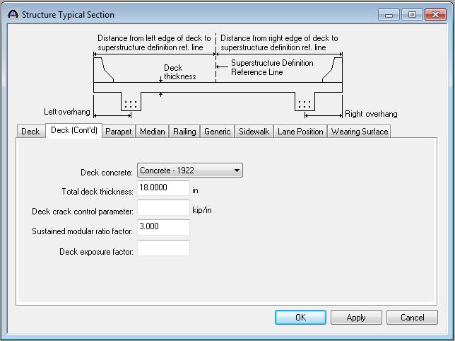
 tab is used to enter information about the deck concrete and thickness.")
11 Typical Section Next define the structure typical section by double-clicking Structure Typical Section in the Bridge Workspace tree. Input the data describing the typical section as shown below. Deck Geometry The Deck (cont d) tab is used to enter information about the deck concrete and thickness. The material to be used for the deck concrete is selected from the list of bridge materials described in the Background section. 11
12 12

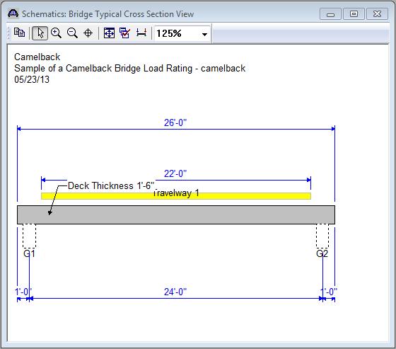
13 Lane Positions Select the Lane Position tab. Manually enter the width of the travelway as shown in the figure below Click OK to save the data to memory and close the window. It is also a good idea to check the schematic after entering the structure typical section information. This is done in the same manner as was used to check the schematic of the framing plan details. Note that for reinforced concrete structures a generic beam shape is used to represent the beam. 13
14 14
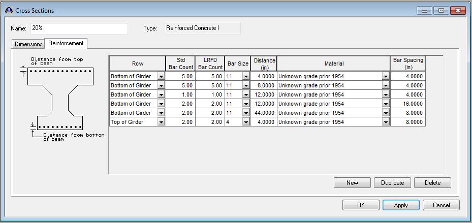
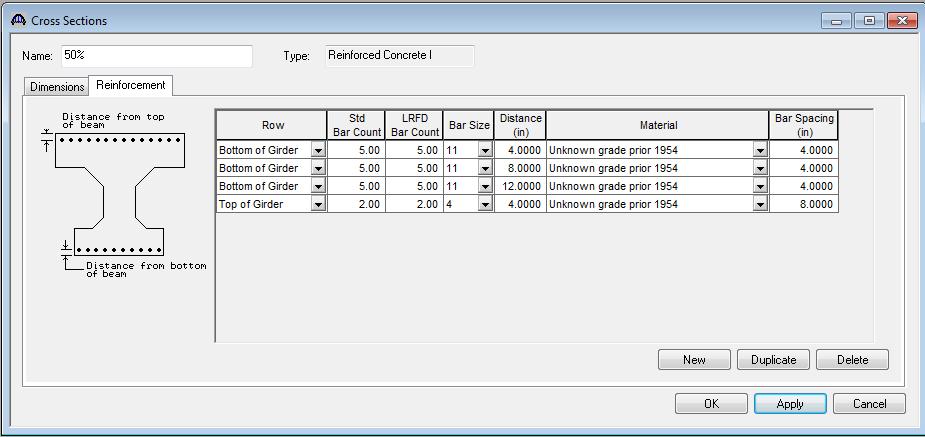
. Define the reinforcement as shown below.")
15 Shear Reinforcement Now define the vertical shear reinforcement by double-clicking on Vertical (under Shear Reinforcement Definitions in the tree). Define the reinforcement as shown below. Click OK to save to memory and close the window. 15

. Double-click MEMBER ALTERNATIVES in the tree to create a new alternative. The New Member Alternative dialog shown below will open.")
16 Member Descriptions The Member window shows the data that was generated when the structure definition was created. No changes are required at this time. The first Member Alternative that we create will automatically be assigned as the Existing and Current Member alternative for this member (as shown below). Double-click MEMBER ALTERNATIVES in the tree to create a new alternative. The New Member Alternative dialog shown below will open. Select Reinforced Concrete for the Material Type and Reinforced Concrete I for the Girder Type. Click OK to close the dialog and create a new member alternative. 16

17 The Member Alternative Description window will open. Enter the appropriate data as shown below. Note: BR will not automatically calculate and include the self-weight of the deck. Therefore, you must estimate the weight of the deck and apply it to the beam as an additional self-load. In this example, the deck is 1.5 feet thick and spans 22 feet between beams. Therefore, the additional self-load can be approximated as 11 ft*1.5 ft*0.150 k/ft 3 = k/ft, which is entered below. By entering the deck weight at this location you are assuming that the deck and slabs were cast as a single unit while supported by false work. If this condition does not appear to be true for your particular bridge you should instead add the deck weight as an additional uniform load under the Member Loads tab. 17

18 Expand Member Alternatives and camelback beam (E)(C) portions of the tree. The default materials for the member alternative must be defined. Enter data as shown in the figure below. 18

19 Open the Live Load Distribution window from the tree beneath camelback beam. If we try to use the Compute from Typical Section button on the Live Load Distribution Standard tab to populate the LFD live load distribution factors for this member alternative, we will receive a message that BR cannot calculate the distribution factors because beam shapes are not assigned to adjacent member alternatives. You must revisit this window after the member alternative has been created for the other side of the bridge. Then the Compute from Typical Section button will compute the distribution factors for you. Cross Sections The camelback shape will be modeled as a series of cross sections located at discrete points. Cross sections should be determined for 10 th points along the length of the bridge. An elevation of half the bridge and half sections for the end and center of the bridge are shown below along with a rebar schedule for interpretation of the reinforcing steel identified in the half sections. The cross section can be modeled as an I-beam. Use the elevation to determine the flange and web heights and the half section to determine the flange and web width and the rebar placement. If the section contains square reinforcing bars substitute those with the largest modern rebar size that produces an equal or lesser cross sectional area. In this example; No. 11 rebar (1.56 in 2 ) was used to represent 1.25-in square rebar (1.56-in 2 ). Additional rebar could be added to bring the total cross sectional area of steel in the model to what is found in the bridge provided no deterioration has occurred. Pay careful attention to any changes in rebar placement at the different cross sections. Steel reinforcing plans and elevations along with bending diagrams have been shown to provide the necessary information to ensure proper rebar locating at each section. 19


20 End 10% 20% 30% 40% 50% Add to all locations Elevation showing dimensions of the top flange/web at various cross sections 20
 21")
21 Stirrups (spacing shown on half elevation, page 2) 21
22 Cross-Sections at End and Mid-Span Longitudinal Steel Placement Note: From the elevation we see that the rebar in the third row from the bottom changes depth over the length of the bridge. The two outer bars (GLE) are located higher in the section and then drop down, followed by the 22
 10% - GLE @ 3-8 from the 3rd")
23 two inner bars (GLF). The center bar (GLC/CLD) remains at the same location over the length. This has been reflected in the cross sections modeled in BR (details on the next page). Description and Bending Details of Longitudinal Girder Reinforcing Steel Cross Section Locations: End - GLE and GLF both up 4-10 from the 3rd row (70 from bottom of beam) 10% from the 3rd row (56 from bottom), 4-10 from 3rd row (70 from bottom) 23
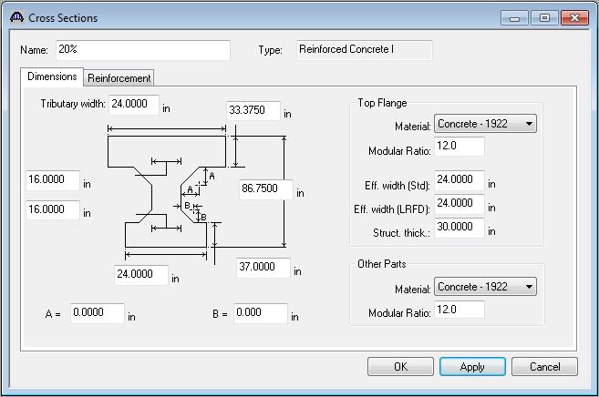
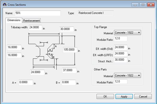
24 20% - 3rd row (12 from bottom), 2-8 from 3rd row (44 from bottom) 30% - GLE and 3rd row (12 inches from bottom of beam) Next describe the beam by double-clicking on Cross Sections in the tree. The Cross Sections windows with the cross sections identified from the plans are shown below. Remember to enter rebar locations as appropriate for the cross section, keeping in mind that these may change over the length of the bridge. In the following cross sections, the #4 rebar at the top of the section was assumed based on scale from the plans. 24
25 25
26 26
27 27
28 28
29 29
30 30
.")
31 Now that the cross sections have been entered we must assign them to the appropriate locations along the beam. Open the Cross Section Ranges window. The cross sections were identified for the end of the beam and then every 6 feet along the bridge length (10 th points). Starting with the end of the beam select the start and end cross sections and then corresponding length between these sections. This model can be further refined with more cross section descriptions and shorter length between cross sections. 31

32 Open the Shear Reinforcement Ranges window and define the location and spacing of shear reinforcement as determined from the plans. 32
33 Next, copy G1 to G2. Do this by right clicking on camelback beam (E)(C), select copy, then right click on MEMBER ALTERNATIVES under G2 and select paste. Now that all beams within the span have been defined we are able to go back to windows within the bridge tree that will require updating. The Live Load Distribution window for both G1 and G2 needs to be updated, select Compute from Typical Section. 33
34 Bridge Alternatives Now that the superstructure definitions are modeled, Bridge Alternatives must be created. This makes it possible to rate the entire bridge at one time and also perform batch processes in the Bridge Explorer workspace, which is important for permitting issues. For load rating, there will typically be only one Bridge Alternative. Another Bridge Alternative could be created for a proposed bridge or rehabilitation project, but only one bridge alternative should be existing/current at a time. Each superstructure that was entered above now needs its own definition in the Bridge Alternative. Select the superstructure wizard. Enter the number of superstructures. Enter the superstructure and superstructure alternative names and then select the superstructure definition that you want to link to each alternative. The bridge alternative portion of the tree may be created manually by double-clicking on each branch and assigning the necessary bridge components to each branch as shown above (Superstructure Wizard button may be selected to aid in this process). Double-click BRIDGE ALTERNATIVES and enter the Alternative Name, then select the Superstructure Wizard button and enter the data shown in the window below. 34

35 Click Finish to close the Superstructure Wizard and OK to save the Bridge Alternative data to memory and close the window. 35

36 Analysis Vehicle Selection From the Bridge menu, select Analysis Settings and load the following vehicles into the rating column: Select OK Note: MDOT trucks 5-DL, 18-DL and 23-DL are used in this analysis as they are the commonly controlling 1-unit, 2-unit and 3-unit trucks, respectively. The load rating engineer should evaluate the list of legal vehicles to determine whether others may control and include them in the analysis if necessary. In addition, if posting is required, all legal loads must be analyzed to determine the lowest tonnage for each vehicle category. 36


37 Analysis Go to Bridge/Analyze. You will be informed regarding progress and completion of the analysis. Reporting Results of the analysis may be viewed using the Report Tool located within the Bridge menu. Select Generate. 37
38 Bridge Name: Sample of a Camelback Bridge Load Rating NBI Structure ID: Camelback Bridge ID: Camelback Analyzed By: Virtis Analyze Date: Friday, June 14, :48:10 Analysis Engine: AASHTO LFR Engine Version Analysis Preference Setting: None Report By: virtis Report Date: Friday, June 14, :50:03 Structure Definition Name: camelback Member Name: G1 Member Alternative Name: camelback beam Load Factor Rating Summary Rating Capacity Location Live Load Factor Controls (Ton) Span (ft) Percent Impact Lane HS Inventory Design Flexure - Concrete As Requested As Requested Operating Design Flexure - Concrete As Requested As Requested Michigan 1 Unit Truck 05-DL Inventory ** ** ** ** ** ** ** ** Operating Design Flexure - Concrete As Requested As Requested Michigan 2 Unit Truck 18-DL Inventory ** ** ** ** ** ** ** ** Operating Design Flexure - Concrete As Requested As Requested Michigan 3 Unit Truck 23-DL Inventory ** ** ** ** ** ** ** ** Operating Design Flexure - Concrete As Requested As Requested Note: "N/A" indicates not applicable "**" indicates not available Bridge Name: Sample of a Camelback Bridge Load Rating NBI Structure ID: Camelback Bridge ID: Camelback 38
39 Analyzed By: Virtis Analyze Date: Friday, June 14, :48:10 Analysis Engine: AASHTO LFR Engine Version Analysis Preference Setting: None Report By: virtis Report Date: Friday, June 14, :50:03 Structure Definition Name: camelback Member Name: G2 Member Alternative Name: Copy of camelback beam Load Factor Rating Summary Rating Capacity Location Live Load Factor Controls (Ton) Span (ft) Percent Impact Lane HS Inventory Design Flexure - Concrete As Requested As Requested Operating Design Flexure - Concrete As Requested As Requested Michigan 1 Unit Truck 05-DL Inventory ** ** ** ** ** ** ** ** Operating Design Flexure - Concrete As Requested As Requested Michigan 2 Unit Truck 18-DL Inventory ** ** ** ** ** ** ** ** Operating Design Flexure - Concrete As Requested As Requested Michigan 3 Unit Truck 23-DL Inventory ** ** ** ** ** ** ** ** Operating Design Flexure - Concrete As Requested As Requested Note: "N/A" indicates not applicable "**" indicates not available 39