CITY OF LA MESA FIRE DEPARTMENT SOLAR PHOTOVOLTAIC INSTALLATION GUIDELINE
|
|
|
- Eleanor Flowers
- 5 years ago
- Views:
Transcription


1 CITY OF LA MESA FIRE DEPARTMENT SOLAR PHOTOVOLTAIC INSTALLATION GUIDELINE April 22, 2008
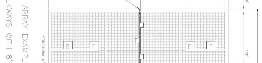
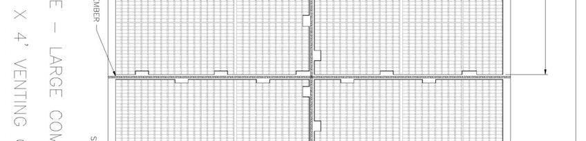
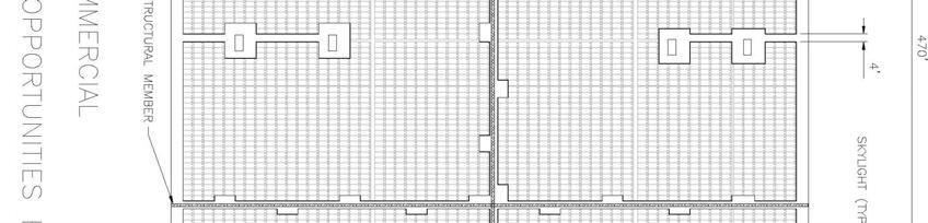
2 SOLAR PHOTOVOLTAIC INSTALLATION GUIDELINE April 22, 2008 TABLE OF CONTENTS 1.0 MARKING MAIN SERVICE DISCONNECT MARKING CONTENT AND FORMAT MARKING FOR DIRECT CURRENT CONDUIT, RACEWAYS, ENCLOSURES, CABLE ASSEMBLIES, AND JUNCTION BOXES MARKING CONTENT AND FORMAT INVERTERS ACCESS, PATHWAYS AND SMOKE VENTILATION RESIDENTIAL SYSTEMS SINGLE AND TWO-UNIT RESIDENTIAL DWELLINGS ACCESS/PATHWAYS SMOKE VENTILATION COMMERCIAL BUILDINGS AND RESIDENTIAL HOUSING COMPRISED OF THREE (3) OR MORE UNITS ACCESS PATHWAYS SMOKE VENTILATION LOCATION OF DIRECT CURRENT (DC) CONDUCTORS NON-HABITABLE BUILDINGS GROUND MOUNTED PHOTOVOLTIAC ARRAYS...7 EXAMPLE 1 CROSS GABLE ROOF...9 EXAMPLE 2 CROSS GABLE WITH VALLEY...9 EXAMPLE 3 FULL GABLE...10 EXAMPLE 4 FULL HIP ROOF...10 EXAMPLE 5 LARGE COMMERCIAL 8 WALKWAYS...11 EXAMPLE 6 LARGE COMMERCIAL 4 WALKWAYS...12 EXAMPLE 7 SMALL COMMERCIAL 4 WALKWAYS...13 EXAMPLE 8 SMALL COMMERCIAL 8 WALKWAYS...14
3 1.0 MARKING PV systems must be marked. Marking is needed to provide emergency responders with appropriate warning and guidance with respect to working around and isolating the solar electric system. This can facilitate identifying energized electrical lines that connect the solar modules to the inverter, as these should not be cut when venting for smoke removal. Materials used for marking must be weather resistant. It is recommended that Underwriters Laboratories Marking and Labeling System 969 (UL 969) be used as standard to determine weather rating. (UL listing of markings is not required). 1.1 Main Service Disconnect For residential applications, the marking may be placed within the main service disconnect. If the main service disconnect is operable with the service panel closed, the marking should be placed on the outside cover. For commercial application, the marking should be placed adjacent to the main service disconnect in a location clearly visible from the location where the lever is operated. All electrical panel shut-offs shall be designed to shut off all power (Solar and Domestic) after the panel. Shut offs sometimes can be located on the roof, generally after an array. If so, the shut-off shall be labeled. (La Mesa Fire) Marking Content and Format MARKING CONTENT: CAUTION: SOLAR ELECTRIC SYSTEM RED BACKGROUND WHITE LETTERING MINIMUM 3/8 LETTER HEIGHT ALL CAPITAL LETTERS ARIAL OR SIMILAR FONT, NON-BOLD REFLECTIVE, WEATHER RESISTANT MATERIAL SUITABLE FOR THE ENVIRONMENT (durable adhesive materials may meet this requirement) CAUTION: SOLAR ELECTRIC SYSTEM 3
4 1.2 Marking for Direct Current Conduit, Raceways, Enclosures, Cable Assemblies, and Junction Boxes Marking is required on all interior and exterior DC conduit, raceways, enclosures, cable assemblies, and junction boxes to alert the Fire Service to avoid cutting them. Marking should be placed on all interior and exterior DC conduit, raceways, enclosures, and cable assemblies, every 10 feet, at turns and above and/or below penetrations and all DC combiner and junction boxes Marking Content and Format MARKING CONTENT: CAUTION: SOLAR CIRCUIT RED BACKGROUND WHITE LETTERING MINIMUM 3/8 LETTER HEIGHT ALL CAPITAL LETTERS ARIAL OR SIMILAR FONT, NON-BOLD REFLECTIVE, WEATHER RESISTANT MATERIAL SUITABLE FOR THE ENVIRONMENT (durable adhesive materials meet this requirement) CAUTION: SOLAR CIRCUIT 1.3 Inverters The inverter is a device used to convert DC electricity from the solar system to AC electricity for use in the building s electrical system or the grid. No markings are required for the inverter. 2.0 ACCESS, PATHWAYS AND SMOKE VENTILATION Access and spacing requirements should be observed in order to: Ensure access to the roof Provide pathways to specific areas of the roof Provide for smoke ventilation opportunities area Provide emergency egress from the roof Local jurisdictions may create exceptions to this requirement where access, pathway or ventilation requirements are reduced due to: 4
5 Proximity and type of adjacent exposures Alternative access opportunities (as from adjoining roofs) Ground level access to the roof area in question Adequate ventilation opportunities beneath solar array (as with significantly elevated or widely-spaced arrays) Adequate ventilation opportunities afforded by module set back from other rooftop equipment (example: shading or structural constraints may leave significant areas open for ventilation near HVAC equipment) Automatic ventilation device New technology, methods, or other innovations that ensure adequate fire department access, pathways and ventilation opportunities Designation of ridge, hip, and valley does not apply to roofs with 2-in-12 or less pitch. All roof dimensions are measured to centerlines. Roof access points should be defined as areas where ladders are not placed over openings (i.e., windows or doors) and are located at strong points of building construction and in locations where they will not conflict with overhead obstructions (i.e., tree limbs, wires, or signs). 2.1 Residential Systems Single and Two-Unit Residential Dwellings All systems require plan review by La Mesa Fire Department. (La Mesa Fire) Access/Pathways a. Residential Buildings with hip roof layouts: Modules should be located in a manner that provides one (1) three-foot (3 ) wide clear access pathway from the eave to the ridge on each roof slope where modules are located. The access pathway should be located at a structurally strong location on the building (such as a bearing wall). b. Residential Buildings with a single ridge: Modules should be located in a manner that provides two (2) three-foot (3 ) wide access pathways from the eave to the ridge on each roof slope where modules are located. c. Hips and Valleys: Modules should be located no closer than one and one half (1.5) feet to a hip or a valley if modules are to be placed on both sides of a hip or valley. If the modules are to be located on only one side of a hip or valley that is of equal length then the modules may be placed directly adjacent to the hip or valley. d. Roof Mount Array layout requirements: Minimum 3 clearance from ridgeline to array edge. Minimum 3 clearance from load-bearing wall of rake to array edge. (La Mesa Fire) 5
6 2.1.2 Smoke Ventilation The modules should be located no higher than three feet (3 ) below the ridge. 2.2 Commercial Buildings and Residential Housing Comprised of Three (3) or More Units Exception: If a local fire department determines that the roof configuration is similar to residential (such as in the case of townhouses, condominiums, or single family attached buildings), the local fire department may make a determination to apply the residential access and ventilation requirements. Examples of these requirements appear at the end of this guideline Access There should be a minimum six foot (6 ) wide clear perimeter around the edges of the roof. Exception: If either axis of the building is 250 feet or less, there should be a minimum four feet (4 ) wide clear perimeter around the edges of the roof, four foot (4 ) from ridge or parapet. (La Mesa Fire) Pathways Pathways should be established in the design of the solar installation. Pathways should meet the following requirements: a. Should be over structural members b. Centerline axis pathways should be provided in both axis of the roof. Centerline axis pathways should run on structural members or over the next closest structural member nearest to the center lines of the roof c. Should be straight line not less than 4 feet (4 ) clear to skylights and/or ventilation hatches d. Should be straight line not less than 4 feet (4 ) clear to roof standpipes e. Should provide not less than 4 feet (4 ) clear around roof access hatch with at least one not less than 4 feet (4 ) clear pathway to parapet or roof edge Smoke Ventilation a. Arrays should be no greater than 50 by 50 feet in distance in either axis (La Mesa Fire) b. Ventilation options between array sections should be either: 1. A pathway 4 feet (4 ) or greater in width (La Mesa Fire) 6
7 2. 4 feet (4 ) or greater in width pathway and bordering on existing roof skylights or ventilation hatches 3. 4 feet (4 ) or greater in width pathway and bordering four feet (4 ) x 8 feet 8 venting cutouts every 20 feet (20 ) on alternating sides of the pathway 3.0 LOCATION OF DIRECT CURRENT (DC) CONDUCTORS Conduit, wiring systems, and raceways for photovoltaic circuits should be located as close as possible to the ridge or hip or valley and from the hip or valley as directly as possible to an outside wall to reduce trip hazards and maximize ventilation opportunities. Conduit runs between sub arrays and to DC combiner boxes should use design guidelines that minimize total amount of conduit on the roof by taking the shortest path from the array to the DC combiner box. The DC combiner boxes are to be located such that conduit runs are minimized in the pathways between arrays. To limit the hazard of cutting live conduit in venting operations, DC wiring should be run in metallic conduit or raceways when located within enclosed specs in a building and should be run, to the maximum extent possible, along the bottom of load-bearing members. 4.0 NON-HABITABLE BUILDINGS This guideline does not apply to non-habitable structures. Examples of non-habitable structures include, but are not limited to, parking shade structures, solar trellises, etc. 5.0 GROUND MOUNTED PHOTOVOLTIAC ARRAYS Setback requirements do not apply to ground-mounted, freestanding photovoltaic arrays. A clear brush area of ten feet (10 ) is required for ground mounted photovoltaic arrays. a) Mounts shall be on noncombustible construction b) Arrays shall be located a minimum of 20 from structure and shall not impeded access to and around a structure in any manner c) No storage shall be permitted under the panel arrays d) Vegetation shall be cleared and maintained underneath the array area e) Array locations shall not locate upon recorded biological conservation easements, riparian or vernal pool areas DEFINITIONS Inverter: Devices that convert dc electricity (single or multiphase), either for stand alone systems (not connected to the grid) or for utility-interactive systems. Photovoltaic (PV): Pertaining to the direct conversion of light into electricity. Array: Any number of photovoltaic modules connected together to provide a single electric output. Arrays are often designed to produce significant amounts of electricity. 7
8 Support Bracket I Frame: Used to secure the panel to the roof and other surfaces. Connectors: Devices used to hold the panels to the framework or brackets. (La Mesa Fire) ***SEE PAGES 9 14 FOR EXAMPLES*** Call La Mesa Fire Prevention Bureau at (619) if you have any questions. 8


9 Draft PV Guideline, April 22, 2008 Diagram 1: Cross Gable Roof EXAMPLE 2 Diagram 2: Cross Gable with Valley 9


10 Draft PV Guideline, April 22, 2008 EXAMPLE 3 Diagram 3: Full Gable EXAMPLE 4 Example 4: Full Hip Roof 10


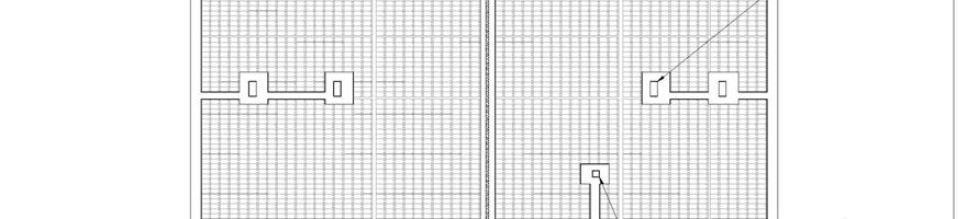
11 Draft PV Guideline, April 22, 2008 EXAMPLE 5 11

12 Draft PV Guideline, April 22, 2008 EXAMPLE 6 12

13 Draft PV Guideline, April 22, 2008 EXAMPLE 7 13
14 Draft PV Guideline, April 22, 2008 EXAMPLE 8 14