PER See all Pei ES Listings at: Report Owner
|
|
|
- Lionel Norton
- 5 years ago
- Views:
Transcription


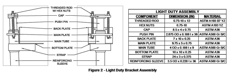
1 Pei Evaluation Service is an accredited ISO Standard Product Certifier, accredited by the IAS. This Product Evaluation Report represents a product that Pei ES has Evaluated and this product has a Follow-up Service / Inspection Agreement. This Product Evaluation Report in no way implies warranty for this product or relieves SafeBasements Inc. of their liabilities for this product. This PER is an official document if it is within one year of the initial or re-approval date. Initial Approval Re-Approved December, 2015 See all Pei ES Listings at: Report Owner Approved Manufacturing Locations SafeBasements Inc. Main Street Fabrications & Manufacturing, LLC US Hwy S Main St Litchfield, MN Brooksville, FL Product SafeBase Push Piers (Light Duty & Standard Duty) Evaluation Report Information SafeBasements contact: Patrick Nevison General Details SafeBase Push Piers are used as support for structures to recover lost elevations and to provide uniform supplemental support to foundations. The SafeBase Push Pier Systems provide structural lift and are intended to stop settlement of the structure. These products are used to repair residential, commercial, and industrial foundation settlement problems, and may be installed in either interior or exterior applications. SafeBase Push Pier Systems have been tested and evaluated for Eccentric Compression strength with a maximum unsupported/unreinforced tube length of 6 inches. This PER does not address seismic loading for this system, or attachment requirements to buildings. Corrosion resistance and longevity shall be addressed by the registered design professional on a job specific basis. SafeBasements Inc. has an Evaluation and Follow-up Service Agreement with Pei Evaluation Service (Pei ES) and an Inspection Agreement with Progressive Engineering, Inc. (Pei). The manufacturing facility has an approved Q.C. Manual to manufacture SafeBase Light Duty and Standard Duty Push Pier Bracket Systems and is audited quarterly by Pei. Product Description SafeBase Push Pier Systems use ASTM A500 Gr. B/C steel tubing with a nominal outside diameter of 2-7/8" and a wall thickness of 0.188" (+/-10%) for the Main Push-Pin and Starter structure. The various system components include the Push-Pin Starter, Push- Pin, Cap (LD or SD), Reinforcing Sleeve, and LD or SD Bracket Assemblies. The Light Duty (LD) Bracket Assembly is manufactured using the following components: Main Tube (HSS 4"x0.188" ASTM A500 Gr. B/C Tube) Bottom Plate (1/4" ASTM A36 Plate) Main Plate (3/4" ASTM A36 Plate) Back Plate (1/4" ASTM A36 Plate) Strap (3/8" ASTM A36 Flat Bar) Threaded Rods (3/4-10 x 12" ASTM A193 B7 YZ) The Standard Duty (SD) Bracket Assembly is manufactured using the following components: Main Tube (HSS 4"x0.188" ASTM A500 Gr. B/C Tube) Bottom Plate (1/2" ASTM A36 Plate) Main Plate (1" ASTM A36 Plate) Back Plate (3/8" ASTM A36 Plate) Strap (3/8" ASTM A36 Flat Bar) Threaded Rods (3/4-10 x 12" ASTM A193 B7 YZ) The Push-Pin Starter is manufactured using the following components: Friction Ring (3" S80 ASTM A53 Grade A) Std. Push-Pin Tube (HSS 2.875"x0.188" ASTM A500 Gr. B/C Tube) The Push-Pin is manufactured using the following components: Std. Push-Pin Tube (HSS 2.875"x0.188" ASTM A500 Gr. B/C Tube) Push-Pin Insert (HSS 2.5"x0.188" ASTM A500 Gr. B/C Tube) The Cap is manufactured using the following components: LD Cap (8.5"x4.0"x0.75" ASTM A36 Flat Bar) SD Cap (8.5"x4.0"x1.0" ASTM A36 Flat Bar) The Reinforcing Sleeve is manufactured using the following components: Support Tube (HSS 3.5"x0.220" ASTM A500 Gr. B/C Tube) Support Ring (HSS 4"x0.188" ASTM A500 Gr. B/C Tube) ver 1.0 Page 1 of 5
2 Design Considerations A structural evaluation Shall be submitted at the request of the building official on a job specific basis with consideration to the existing foundation, soil conditions, and overall system integrity. Building Code Compliance Table 1 - Applicable Code Sections 2012 & 2015 International Residential Code 2012 & 2015 International Building Code Section R Section R Section Section Section R Section R Section General Product Usage and Limitations 1. A site survey is necessary of the area where the Piers are going to be driven to locate any possible interference such as utilities, plumbing, electrical or phone lines. 2. Pier placement should begin no further than 2-feet from any corner with piers typically spaced between 2-feet and 6-feet on center. Spaces between piers greater than 6-feet shall be verified by the Engineer of Record. 3. Presence of footing cracks requires appropriate strength square steel tubing (determined by Engineer of Record) to span the cracks between pier brackets. 4. The bearing area around the footing must be a smooth and level condition while adjusting the face of the stem wall to vertical at the point of the bracket attachment. The footings shall be notched in accordance with the SafeBase Push Pier Installation Instructions where required. 5. The utility bracket may be anchored to the foundation utilizing four - 1/2-inch diameter by 5-inch long Titan HD anchors or equivalent. Anchors are meant to hold the bracket tight to the foundation when necessary. SafeBase Push Piers are not rated for uplift loading. 6. The existing structure is used as a reaction force with a hydraulic pump and cylinder combination to drive the pier into the soil. 7. Adjacent piers shall NOT be advanced simultaneously. 8. Each Pier System installed must follow SafeBase Push Pier Installation Instructions. In accordance with the 2012 and 2015 IRC Section , a copy of these installation instructions shall be made available on the job site at the time of installation. 9. When installed under structures meeting the requirements of the 2012 or 2015 IBC, a continuous special inspection shall be performed during installation when specifically required by the building official and/or registered design professional. 10. The allowable capacities shown in Table 2 reflect installation in soils capable of sufficient lateral support of the push pier in accordance with Section of the 2012 & 2015 IBC. Where fluid soils (as defined by the 2012 & 2015 IBC) are present or the the foundation elements stand unbraced in air or water, it shall be permitted to consider them laterally supported at a point 5-feet into stiff or 10-feet into soft soil unless otherwise verified through a geotechnical investigation by a registered design professional. 11. A registered design professional shall verify the installation meets the minimum stability requirements of Section of the 2012 & 2015 IBC. 12. SafeBase Push Piers are rated for compression loading only. Lateral and uplift loading from wind and seismic shall be carried by the existing shallow foundation and verified by a registered design professional. Product Labeling Each Pier System that is covered by this PER, must be marked with the following information: 1. SafeBase Product Number 2. This PER Number & Pei ES Name or Logo 3. Bracket Load Rating 4. Manufacturer Address Acceptable Evaluation Marks Product Documentation SafeBasements Quality Assurance Manual - Dated: October 1, SafeBase Push Pier Installation Instructions - Dated: October 27, 2015 A Pei test report No (A) - Eccentric Compression Test on a SafeBase Push Pier - LD Bracket - Dated: October 14, 2015 A Pei test report No (B) - Eccentric Compression Test on a SafeBase Push Pier - SD Bracket - Dated: October 15, 2015 Engineering Calculations for SafeBase Push Pier - SD & LD Bracket - Dated: November 9, 2015 Page 2 of 5
3 Model Table 2 - Push Pier Bracket Compression Load Ratings 1 Product Designation Average Tested Yield Capacity (lbs) Average Tested Ultimate Capacity (lbs) Allowable Bracket Capacity (lbs) 2 Adjusted for Corrosion Loss (lbs) 3 Push Pier Light Duty (LD) 36,800 69,700 22,000 19,800 Bracket Standard Duty Push Pier 57,300 76,300 34,300 31,600 (SD) Bracket Notes: 1. Table provides tested bracket capacities only. A licensed engineer shall verify the actual available capacity based on the size of the push pin, expected corrosion loss, and the site specific soil conditions. 2. Allowable capacities are based upon the minimum of the average tested yield capacity (P y ) multiplied by 0.6 and the average tested ultimate capacity multiplied by (0.5). Allowable capacities shall be utilized with Allowable Strength Design (ASD) loading. 3. Corrosion adjustment is based upon a 50-year sacrificial thickness of in and calculated in accordance with Section 3.9 of ICC-ES AC358. This value is supplied for reference only and the registered design professional shall determine the actual corrosion loss and required longevity on a job specific basis. Page 3 of 5

4 Page 4 of 5

5 Page 5 of 5